EP3495171A1 - Reifendrucküberwachungseinheit - Google Patents
Reifendrucküberwachungseinheit Download PDFInfo
- Publication number
- EP3495171A1 EP3495171A1 EP18190376.6A EP18190376A EP3495171A1 EP 3495171 A1 EP3495171 A1 EP 3495171A1 EP 18190376 A EP18190376 A EP 18190376A EP 3495171 A1 EP3495171 A1 EP 3495171A1
- Authority
- EP
- European Patent Office
- Prior art keywords
- electronics housing
- tire
- monitoring unit
- air inlet
- pressure monitoring
- Prior art date
- Legal status (The legal status is an assumption and is not a legal conclusion. Google has not performed a legal analysis and makes no representation as to the accuracy of the status listed.)
- Granted
Links
Images


Classifications
-
- B—PERFORMING OPERATIONS; TRANSPORTING
- B60—VEHICLES IN GENERAL
- B60C—VEHICLE TYRES; TYRE INFLATION; TYRE CHANGING; CONNECTING VALVES TO INFLATABLE ELASTIC BODIES IN GENERAL; DEVICES OR ARRANGEMENTS RELATED TO TYRES
- B60C23/00—Devices for measuring, signalling, controlling, or distributing tyre pressure or temperature, specially adapted for mounting on vehicles; Arrangement of tyre inflating devices on vehicles, e.g. of pumps or of tanks; Tyre cooling arrangements
- B60C23/02—Signalling devices actuated by tyre pressure
- B60C23/04—Signalling devices actuated by tyre pressure mounted on the wheel or tyre
- B60C23/0491—Constructional details of means for attaching the control device
- B60C23/0494—Valve stem attachments positioned inside the tyre chamber
Definitions
- the invention relates to a tire pressure monitoring unit for a motor vehicle according to the preamble of patent claim 1.
- Vehicle safety and reliability are key aspects in automotive engineering. Therefore, alone for safety reasons, the tire pressure of vehicles or motor vehicles should be checked regularly, but this is often missed by the driver. For this reason, detection devices in the form of tire pressure sensors are increasingly used in modern vehicles, which automatically measure the tire air pressure and send it to a vehicle-side control unit. As a result, defects or accidents, which are due to a low tire air pressure, are avoided. Consequently, by means of this automatic measurement of the tire air pressure, a critical deviation of the measured tire air pressure from a tire pressure setpoint is to be detected early and displayed to the vehicle driver, so that manual checking is unnecessary.
- a tire pressure monitoring system often includes a tire valve that can be attached to the rim and an electronics housing.
- the reference valve may be a metal valve or a snap-in valve to which the electronics housing can be fastened.
- electronic components in particular a sensor for detecting the tire inflation pressure and / or the temperature and a battery and a transmitting unit can be arranged.
- an air inlet opening is arranged, which is arranged concentrically to the sensor for detecting the tire air pressure in order to measure the tire pressure within the tire. If necessary, the transmitting unit transmits the measured tire pressure information to an evaluation electronics, which may, however, also be provided on the vehicle side.
- the invention provides that in the sealing surface of the seal receiving a groove-shaped recess is formed.
- the particular advantage of the invention is that the seal receptacle brings two functions with it.
- the seal is aligned in the corresponding position to the pressure sensor and the air inlet opening, which is formed in the electronics housing.
- the sealing surface de gasket has the groove-shaped recess, which together with the air inlet opening in the electronics housing and the air passage opening in the seal form a channel to the pressure sensor.
- a measure improving the invention provides that the pressure sensor has a pressure sensor opening, wherein the center axis of the pressure sensor opening of the pressure sensor and the center axis of the air inlet opening of the electronics housing are arranged in parallel.
- This arrangement brings for the Manufacturing a decisive advantage, because there are no auxiliary devices such. B additional slides etc. are needed for the injection molding process. This would be the case if the two central axes of the pressure sensor opening and the air inlet opening, for example, would be perpendicular to each other.
- Another advantage results from such an arrangement that in case of clogged air inlet opening of the electronics housing with dirt particles by the centrifugal force generated during acceleration of the motor vehicle wheel, the blockage is resolved. So it comes to a self-cleaning of the air inlet opening in the electronics housing.
- the air passage opening of the seal and the pressure sensor opening of the pressure sensor can be arranged concentrically. In this way, it is ensured that the pressure to be measured can be reliable, since the two openings are exactly on top of each other.
- the construction is very inexpensive and simple if the air inlet opening in the electronics housing has a diameter of 0.8 to 1.5 mm.
- the air inlet opening in the electronics housing has an area greater than 0.8 mm 2 . This has the advantage that the self-cleaning function can be done reliably.
- the air inlet opening in the electronics housing is conically formed from the inside to the outside, so that the self-cleaning of the air inlet opening can be made even more reliable.
- the air inlet opening in the electronics housing has a height of 2 to 15 mm. Due to the height of 2 to 15 mm of the air inlet opening in the electronics housing has been shown that the damage of the pressure sensor can be more reliably prevented by the laterally under pressure entering fluid into the air inlet opening of the electronics housing.
- a protective wall is formed in the region of the air inlet opening. Also, by means of the protective wall, the damage of the pressure sensor can be avoided by the laterally under pressure entering fluid into the air inlet opening of the electronics housing even more reliable.
- the groove-shaped recess may have a length of greater than 0.8 mm.
- the length of greater than 0.8 mm no overlap of the air inlet opening in the electronics housing and the pressure sensor opening take place, which further prevents damage to the pressure sensor.
- the electronics housing can have at least one first air inlet opening and one second air inlet opening in the electronics housing, wherein the two air inlet openings can be connected by means of the groove-shaped recess.
- the electronic components arranged in the electronics housing are surrounded by potting compound.
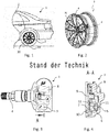
- FIG. 1 The rear of a vehicle 1 and a seated on a rim 30, rear pneumatic tire 20 can be seen.
- a tire valve 4 protrudes from the rim 30.
- a tire pressure monitoring unit 2 is attached. The tire valve 4 and the tire pressure monitoring unit 2 together form a tire pressure monitoring system 3.
- FIG. 3 a tire pressure monitoring system 3 is shown which is already known from the prior art.
- FIG. 4 Fig. 3 is a sectional view of the tire pressure monitoring system 3 according to a prior art.
- the electronic components such as a printed circuit board 9, a pressure sensor 7, battery 13 and a transmitter for wireless transmission of the at least one tire-specific parameter etc. are fixed by means of at least one fastening dome 10 in an electronics housing 8, in particular heat stalked.
- an air inlet opening 5 is formed in the electronics housing 8.
- a cylindrical silicone gasket 6 which has an air passage opening 12.
- the air inlet opening 5 and the air passage opening 12 are concentrically aligned.
- the fluid or dirt particles located inside the tire can hit unhindered under pressure on the pressure sensor 7 and damage it.
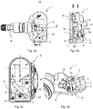
- FIG. 5a an exploded view of a tire pressure monitoring system 3 according to the first embodiment of the invention is shown.
- the tire pressure monitoring system 3 has a tire valve 4 and a tire pressure monitoring unit 2.
- the tire pressure monitoring unit 2 comprises an electronics housing 8 with a cavity in which electronic components such as a printed circuit board 9, a battery 13, a pressure sensor 7, a microcontroller and a transmitter can be arranged. Further, at least one continuous air inlet opening 5 is arranged in the electronics housing 8, wherein between the pressure sensor 7 and the air inlet opening 5, a seal 6 in one provided receptacle 40 is inserted in the electronics housing 8.
- the tire valve 4 is inserted into a continuous opening on the rim and secured with a union nut.
- the tire pressure monitoring unit 2 is fastened with a screw 80 in the cavity of the tire.
- the pressure measured by the pressure sensor 7 is z. B to a vehicle-side control unit, in particular ECU sent.
- FIG. 5b is a bottom view of an electronics housing 8 of a tire pressure monitoring unit 2 according to the first embodiment of the invention shown.
- the seal receptacle 40 has a cylindrical shape with a lateral surface 41 and a sealing surface 14.
- a groove-shaped recess 15 is formed in the sealing surface 14.
- the groove-shaped recess 15 may have round ends.
- the groove-shaped recess 15 is connected to the air inlet opening 5.
- the air inlet opening 5 of the electronics housing 8 may have a diameter of 0.8 to 1.5 mm.
- the groove-shaped recess 15 may have a length of greater than 0.8 mm.
- the groove-shaped recess 15 may have a height greater than 0.8 mm.
- the groove-shaped recess 15 may have a width which corresponds to the diameter of the air inlet opening 5.
- the gasket 6 has a cylindrical shape with a continuous air passage opening 12.
- the air inlet opening 5 and the groove-shaped recess 15 and the air passage opening 12 form a channel to the pressure sensor, wherein the air inlet opening 5 and the air passage opening 12 are arranged offset by means of the groove-shaped recess 15.
- the channel may have substantially the same cross-sectional area over the entire course.
- FIG. 5c 1 is a top view of the tire pressure monitoring unit 2 according to the first embodiment of the invention. Through the air inlet opening 5, a section CC is indicated.
- FIG. 5d is a sectional view CC of the tire pressure monitoring unit 2 according to the first embodiment of the invention shown.
- fastening domes 10 are in the cavity of the electronics housing 8 educated.
- the printed circuit board 9 with the pressure sensor 7 arranged thereon is pressed against the sealing surface 14 and connected under prestress to the seal 6 by means of the fastening domes 10 with the electronics housing 8.
- the conical mounting domes 10 are inserted into the mounting holes 17 of the circuit board 9. Subsequently, the ends of the fixing dome 10 are hot-staked. As a result, the ends of the fastening domes 10 deform mushroom-shaped, so that the circuit board 9 is securely fixed against vibration in the electronics housing 8.
- the air inlet opening 5 formed in the electronics housing 8 is surrounded by a tower 18 which serves to protect against lateral irradiation of the fluid located in the interior of the pneumatic tire as well as against direct injection with a hot water damper.
- the tower 18 is frightened radially outwardly from the surface of the electronics housing 8, and the height of the tower 18 is cylindrical in shape, with a height of 3 to 15 mm.
- the outer diameter of the tower 18 is formed larger than the air inlet opening 5.
- FIG. 5e is a perspective view of a section through the electronics housing 8 of the tire pressure monitoring unit 2 according to the first embodiment of the invention shown.
- FIGs 6a-6d there is shown a tire pressure monitoring system 3 according to the second embodiment of the present invention.
- the tire pressure monitoring system 3 has a tire valve 4 and a tire pressure monitoring unit 2.
- the second embodiment has the same construction as the first embodiment with only a single difference.
- the tower 18 described in the first embodiment is omitted, which serves to protect against lateral irradiation of the fluid located inside the tire or small particles as well as against direct injection with a H thoroughlywasserdammpfstahler in the pressure sensor 7. Instead, a circular segment-shaped rib 16 is formed around the air inlet opening 5 in the electronics housing 8.
- the circular segment-shaped rib 16 is frightened radially outwardly from the surface of the electronics housing 8 and the height of the rib 16 has a length of at least one Eighth of a circle and a height of at least 2 mm.
- the rib 16 may be disposed at an angle W of 0 to 80 degrees from the center axis M of the tire valve 4.
- FIGS. 7a-7d a tire pressure monitoring system 3 according to the third embodiment of the invention is shown.
- the tire pressure monitoring system 3 has a tire valve 4 and a tire pressure monitoring unit 2.
- the tire pressure monitoring unit 2 comprises an electronics housing 8 with a cavity in which electronic components such as a printed circuit board 9, a battery 13, a pressure sensor 7, a microcontroller and a transmitter can be arranged. Further, two continuous air inlet openings 5, 50 are arranged in the electronics housing 8, wherein between the pressure sensor 7 and the air inlet openings 5, 50 a seal 6 in a receptacle 40 provided in the electronics housing 8 is inserted.
- the tire valve 4 is inserted into a through opening in the rim 30 and secured with a union nut.
- the tire pressure monitoring unit 2 is fastened with a screw 80 in the cavity of the tire.
- the pressure measured by the pressure sensor 7 is z. B to a vehicle-mounted control unit, in particular ECU sent.
- the seal receptacle 40 has a cylindrical shape with a lateral surface 41 and a sealing surface 14.
- a groove-shaped recess 15 is formed in the sealing surface 14.
- the groove-shaped recess 15 may have round ends.
- the groove-shaped recess 15 is connected to the two air inlet openings 5, 50.
- the air inlet openings 5, 50 in the electronics housing 8 may each have a diameter of 0.8 to 1.5 mm.
- the groove-shaped recess 15 may have a length of greater than 0.8 mm.
- the groove-shaped recess 15 may have a height greater than 0.8 mm.
- the groove-shaped recess 15 may have a width which corresponds to the diameter of the air inlet opening 5.
- the gasket 6 has a cylindrical shape with a continuous air passage opening 12.
- the air inlet openings 5, 50 and the groove-shaped recess 15 and the air passage opening 12 form a channel to the pressure sensor, wherein the Air inlet openings 5, 50 and the air passage opening 12 are connected to the groove-shaped recess 15. Furthermore, the air inlet openings 5, 50 and the air passage opening 12 are arranged offset.
- the tower 18 or the circular segment-shaped rib 16, as already disclosed in the first and second embodiments serve to protect the pressure sensor 7 against lateral exposure of the fluid inside the tire or against small particles as well as against direct injection with a H thoroughlywasserdammpfstahler.
- the rib 16 and / or the tower 18 may seal the air inlet opening 5 in front of a sealant exiting from the tire valve 4, which is used in a leaky vehicle tire.
- the cavity in the electronics housing which is provided for the electronic components, is closed tightly with a lid, in particular by means of a laser welding method.
- the cavity in the electronics housing or the mounting opening can be filled with potting compound to protect the electronic components from moisture and to ensure the fatigue strength of the pressure monitoring unit.
- a snap-in valve can be used instead of the metal valve 4 for fastening the tire pressure monitoring unit 2 to the rim 30.
Landscapes
- Engineering & Computer Science (AREA)
- Mechanical Engineering (AREA)
- Measuring Fluid Pressure (AREA)
Abstract
Description
- Die Erfindung betrifft eine Reifendrucküberwachungseinheit für ein Kraftfahrzeug gemäß dem Oberbegriff des Patentanspruchs 1.
Die Fahrzeugsicherheit und Zuverlässigkeit sind zentrale Aspekte in der Automobiltechnik. Daher sollte allein schon aus sicherheitstechnischen Gründen der Reifendruck von Fahrzeugen bzw. Kraftfahrzeugen regelmäßig überprüft werden, was jedoch häufig vom Fahrzeugführer versäumt wird. Aus diesem Grund werden in modernen Fahrzeugen vermehrt Erfassungsvorrichtungen in Form von Reifendrucksensoren verwendet, die den Reifenluftdruck automatisch messen und an ein fahrzeugseitiges Steuergerät senden. Dadurch sollen Defekte oder Unfälle, welche auf einen zu niedrigen Reifenluftdruck zurückzuführen sind, vermieden werden. Folglich soll durch diese automatische Messung des Reifenluftdrucks eine kritische Abweichung des gemessenen Reifenluftdrucks von einem Reifendrucksollwert frühzeitig erkannt und dem Fahrzeugführer angezeigt werden, so dass eine manuelle Überprüfung entbehrlich ist. Bei solchen Systemen zur automatischen Messung des Reifenluftdrucks ist jeweils ein Reifendrucksensor an jedem Rad bzw. Luftreifen angeordnet. Eine Reifendrucküberwachungssytem umfasst dabei oft ein Reifenventil, das an der Felge befestigbar ist und ein Elektronikgehäuse. Beim Refenventil kann es sich um ein Metallventil oder ein Snapinventil handeln, an welches das Elektronikgehäuse befestigbar ist. In dem Elektronikgehäuse können elektronische Bauteile, insbesondere ein Sensor zur Erfassung des Reifenluftdrucks und/oder der Temperatur und eine Batterie sowie eine Sendeeinheit, angeordnet sein. Im Elektronikgehäuse ist eine Lufteinlassöffnung angeordnet, welche konzentrisch zum Sensor zur Erfassung des Reifenluftdrucks angeordnet ist, um den Reifendruck innerhalb des Reifens zu messen. Die Sendeeinheit übermittelt die gemessenen Reifendruckinformationen gegebenenfalls an eine Auswerteelektronik, die aber auch fahrzeugseitig vorgesehen sein kann. Bei der konzentrischen Anordnung der Lufteinlassöffnung zum Drucksensor hat sich herausgestellt, dass im Reifen befindliche Fluide bzw. kleine Partikel oder Reifendichtmittel eine Schädigung des Drucksensors durch direkte Einstrahlung verursachen können, wenn die Fluide bzw. kleine Partikel oder Reifendichtmittel unter Druck durch die Lufteinlassöffnung auf den Drucksensor treffen. Des Weiteren ist eine Schädigung des Drucksensors durch direkten Einstrahl mit einem Heißwasserdammpfstahler. Dies ist ist immer dann der Fall, wenn die Felge mit dem daran befestigten Reifendrucküberwachungssytem mit einem Heißwasserdampfstrahl gereinigt wird.
Der vorliegenden Erfindung liegt die Aufgabe zugrunde, den Drucksensor in kostengünstiger und zuverlässiger Weise vor Beschädigungen zu schützen. - Die erfindungsgemäße Aufgabe wird durch eine Reifendrucküberwachungseinheit mit dem kennzeichnenden Teil des Patentanspruchs 1 und durch ein Reifendrucküberwachungssystem mit dem kennzeichnenden Teil des Patentanspruchs 12 gelöst. In den abhängigen Ansprüchen sind vorteilhafte und besonders zweckmäßige Ausgestaltungen der Erfindung angegeben.
- Dazu ist erfindungsgemäß vorgesehen, dass in der Dichtfläche der Dichtungsaufnahme eine nutförmige Ausnehmung ausgebildet ist. Der besondere Vorteil der Erfindung ist, dass die Dichtungsaufnahme zwei Funktionen mit sich bringt. Zum Einen wird die Dichtung in der entsprechenden Position zum Drucksensor und der Lufteinlasssöffnung, welche im Elektronikgehäuse ausgebildet ist, ausgerichtet. Zum Anderen weist die Dichtfläche de Dichtungsaufnahme die nutförmige Ausnehmung auf, welche zusammen mit der Lufteinlasssöffnung im Elektronikgehäuse und der Luftdurchlassöffnung in der Dichtung einen Kanal zum Drucksensor bilden. Dadurch wird eine direkte Einstrahlung des im Reifen befindlichen Fluides oder mit dem Dampfstrahl auf den Drucksensor vermieden, so dass eine Schädigung des Drucksensors ausgeschlossen ist. Das beschleunigte Fluid wird zuerst entweder durch die Innenwände der Lufteinlasssöffnung im Elektronikgehäuse oder durch die Dichtung abgebremst.
- Eine die Erfindung verbessernde Maßnahme sieht vor, dass der Drucksensor eine Drucksensoröffnung aufweist, wobei die Mittelachse der Drucksensoröffnung des Drucksensors und die Mittelachse der Lufteinlassöffnung des Elektronikgehäuses parallel angeordnet sind. Diese Anordnung bringt für die Fertigung einen entscheidenden Vorteil mit, weil es keine Hilfsvorrichtungen wie z. B zusätzliche Schieber etc. für den Spritzgießprozess benötigt werden. Dies wäre dann der Fall, wenn die beiden Mittelachsen des Drucksensoröffnung und der Lufteinlassöffnung z.B. senkrecht zueinander stehen würden. Ein weiterer Vorteil ergibt sich aus derartiger Anordnung, dass bei eventuell verstopfter Lufteinlassöffnung des Elektronikgehäuses mit Schmutzpartikeln durch die beim Beschleunigen des Kraftfahrzeugrads entstehende Zentrifugalkraft die Verstopfung aufgelöst wird. Es kommt also zu einer Selbstreinigung der Lufteinlassöffnung im Elektronikgehäuse.
- Vorzugsweise können die Luftdurchlassöffnung der Dichtung und die Drucksensoröffnung des Drucksensors konzentrisch angeordnet sein. Auf diese Weise ist es gewährleistet, dass der zu messende Druck zuverlässig erfolgen kann, da die beiden Öffnungen genau übereinander liegen.
- Sehr kostengünstig und einfach ist die Konstruktion, wenn die Lufteinlassöffnung im Elektronikgehäuse einen Durchmesser von 0,8 bis 1,5 mm aufweist.
- Ebenfalls ist es denkbar, dass die Lufteinlassöffnung im Elektronikgehäuse eine Fläche von größer als 0,8 mm2 aufweist. Das hat den Vorteil, dass die Selbstreinigungsfunktion zuverlässig erfolgen kann. Vorteilhafterweise ist, wenn die Lufteinlassöffnung im Elektronikgehäuse von innen nach aussen konisch ausgebildet ist, sodass die Selbstreinigung der Lufteinlassöffnungnoch zuverlässiger erfolgen kann.
- Weiterhin kann gemäß der Erfindung vorgesehen sein, dass die Lufteinlassöffnung im Elektronikgehäuse eine Höhe von 2 bis 15 mm aufweist. Durch die Höhe von 2 bis 15 mm der Lufteinlassöffnung im Elektronikgehäuse hat sich gezeigt, dass die Beschädigung des Drucksensors durch das seitlich unter Druck eintretende Fluid in die Lufteinlassöffnung des Elektronikgehäuses noch zuverlässiger vermieden werden kann.
- Ebenfalls ist es denkbar, dass im Bereich der Lufteinlassöffnung eine Schutzwand ausgebildet ist. Auch mittels der Schutzwand kann die Beschädigung des Drucksensors durch das seitlich unter Druck eintretende Fluid in die Lufteinlassöffnung des Elektronikgehäuses noch zuverlässiger vermieden werden.
- Vorteilhafterweise kann die nutförmige Ausnehmung eine Länge von größer als 0,8 mm aufweisen. Durch die Länge von größer als 0,8 mm kann keine Überlappung der Lufteinlassöffnung im Elektronikgehäuse und des Drucksensoröffnung stattfinden, was weiterhin die Schädigung des Drucksensors vorbeugt.
- In einer weiteren die Erfindung verbessernden Ausführungsform kann das Elektronikgehäuse mindestens eine erste Lufteinlassöffnung und eine zweite Lufteinlassöffnung im Elektronikgehäuse aufweisen, wobei die beiden Lufteinlassöffnungen mittels der nutförmigen Ausnehmung verbindbar sind. Bei zwei Lufteinlassöffnungen im Elektronikgehäuse ist die Wahrscheinlichkeit der Verstopfung mit Schmutzpartikeln geringer als bei nur einer Lufteinlassöffnung, sodass eine zuverlässige Druckmessung erfolgen kann.
- Um die Dichtigkeit zu verbessern, kann vorgesehen sein, dass die im Elektronikgehäuse angeordneten elektronischen Bauteile von Vergussmasse umgeben sind.
- Ebenfalls ist denkbar, dass die im Elektronikgehäuse angeordneten elektronischen Bauteile mit einem Deckel dicht, insbesondere mittels eines Laserschweissverfahrens, verschließbar sind.
Es versteht sich, dass die vorstehend genannten und nachstehend noch zu erläuternden Merkmale nicht nur in der jeweils angegebenen Kombination, sondern auch in anderen Kombinationen oder in Alleinstellung verwendbar sind, ohne den Rahmen der vorliegenden Erfindung zu verlassen. Der Rahmen der Erfindung ist nur durch die Ansprüche definiert. - Weitere Einzelheiten, Merkmale und Vorteile des Gegenstandes der Erfindung ergeben sich aus der nachfolgenden Beschreibung im Zusammenhang mit der Zeichnung, in der beispielhafte bevorzugte Ausführungsbeispiele der Erfindung dargestellt sind. In der Zeichnung zeigt:
-
Figur 1 den hinteren Teil eines Fahrzeugs mit einer Felge, einem Luftreifen und einem Reifenventil, -
Figur 2 eine perspektivische Darstellung auf eine Felge, an der ein Reifendrucküberwachungssystem gemäß der vorliegenden Erfindung angebracht ist, -
Figur 3 ein Reifendrucküberwachungssystem gemäß eines Standes der Technik, -
Figur 4 eine Schnittdarstellung des Reifendrucküberwachungssystem gemäß eines Standes der Technik, -
Figur 5a eine Explosionsdarstellung eines Reifendrucküberwachungssystems gemäß der ersten erfindungsgemäßen Ausführungsform, -
Figur 5b eine Ansicht von unten eines Elektronikgehäuses einer Reifendrucküberwachungseinheit gemäß der ersten erfindungsgemäßen Ausführungsform, -
Figur 5c eine Ansicht von oben der Reifendrucküberwachungseinheit gemäß der ersten erfindungsgemäßen Ausführungsform, -
Figur 5d eine Schnittdarstellung der Reifendrucküberwachungseinheit gemäß der ersten erfindungsgemäßen Ausführungsform, -
Figur 5e eine perspektivische Darstellung eines Schnittes durch das Elektronikgehäuse der Reifendrucküberwachungseinheit gemäß der ersten erfindungsgemäßen Ausführungsform, -
Figur 6a ein Reifendrucküberwachungssystem gemäß der zweiten erfindungsgemäßen Ausführungsform, -
Figur 6b eine Schnittdarstellung einer Reifendrucküberwachungseinheit gemäß der zweiten erfindungsgemäßen Ausführungsform, -
Figur 6c eine Ansicht von unten eines Elektronikgehäuses einer Reifendrucküberwachungseinheit gemäß der zweiten erfindungsgemäßen Ausführungsform, -
Figur 6d eine perspektivische Darstellung eines Schnittes durch das Elektronikgehäuse der Reifendrucküberwachungseinheit gemäß der zweiten erfindungsgemäßen Ausführungsform, -
Figur 7a ein Reifendrucküberwachungssystem gemäß der dritten erfindungsgemäßen Ausführungsform, -
Figur 7b eine Schnittdarstellung einer Reifendrucküberwachungseinheit gemäß der dritten erfindungsgemäßen Ausführungsform, -
Figur 7c eine perspektivische Darstellung eines Schnittes durch ein Elektronikgehäuse der Reifendrucküberwachungseinheit gemäß der dritten erfindungsgemäßen Ausführungsform, -
Figur 7d eine Ansicht von unten eines Elektronikgehäuses der Reifendrucküberwachungseinheit gemäß der dritten erfindungsgemäßen Ausführungsform, - In
Figur 1 ist das Heck eines Fahrzeuges 1 und ein auf einer Felge 30 sitzender, hinterer Luftreifen 20 zu sehen. InFigur 2 ragt ein Reifenventil 4 aus der Felge 30 hervor. An dessen Ventilfuss eine Reifendrucküberwachungseinheit 2 befestigt ist. Das Reifenventil 4 und die Reifendrucküberwachungseinheit 2 bilden zusammen ein Reifendrucküberwachungssystem 3. - In
Figur 3 ist ein Reifendrucküberwachungssystem 3 gezeigt, welches bereits aus dem Stand der Technik bekannt ist. - In
Figur 4 ist eine Schnittdarstellung des Reifendrucküberwachungssystem 3 gemäß eines Standes der Technik gezeigt. Dabei sind die elektronischen Bauteile wie eine Leiterplatte 9, ein Drucksensor 7 , Batterie 13 sowie ein Sender zum drahtlosen Übertragen des mindestens einen reifenspezifischen Parameters etc. mittels mindestens eines Befestigungsdoms 10 in einem Elektronikgehäuse 8 befestigt, insbesondere heißverstemmt. Im Elektronikgehäuse 8 ist eine Lufteinlassöffnung 5 ausgebildet. Zwischen dem Drucksensor 7 und der Lufteinlassöffnung 5 befindet sich eine zylinderförmige Silikondichtung 6, welche eine Luftdurchlassöffnung 12 aufweist. Die Lufteinlassöffnung 5 und die Luftdurchlassöffnung 12 sind konzentrisch ausgerichtet. Hier kann das im Reifeninneren befindliche Fluid bzw. Schmutzpartikeln ungehindert unter Druck auf den Drucksensor 7 treffen und diesen beschädigen. - In
Figur 5a ist eine Explosionsdarstellung eines Reifendrucküberwachungssystems 3 gemäß der ersten erfindungsgemäßen Ausführungsform gezeigt. Das Reifendrucküberwachungssystem 3 weist ein Reifenventil 4 und eine Reifendrucküberwachungseinheit 2 auf. Die Reifendrucküberwachungseinheit 2 umfasst ein Elektronikgehäuse 8 mit einem Hohlraum, in dem elektronische Bauteile wie eine Leiterplatte 9, eine Batterie 13, ein Drucksensor 7, ein Mikrocontroller sowie ein Sender angeordnet sein können. Ferner ist mindestens eine durchgehende Lufteinlassöffnung 5 im Elektronikgehäuse 8 angeordnet, wobei zwischen dem Drucksensor 7 und der Lufteinlassöffnung 5 eine Dichtung 6 in einer dafür vorgesehenen Aufnahme 40 im Elektronikgehäuse 8 eingelegt ist. Das Reifenventil 4 wird in eine durchgehende Öffnung an der Felge gesteckt und mit einer Überwurfmutter befestigt. An einem Aussenende des Reifenventils 4 wird die Reifendrucküberwachungseinheit 2 mit einer Schraube 80 im Hohlraum des Reifen befestigt. Der durch den Drucksensor 7 gemessene Druck wird z. B an eine fahrzeigseitige Steuereinheit, insbesondere ECU, gesendet. - In
Figur 5b ist eine Ansicht von unten eines Elektronikgehäuses 8 von einer Reifendrucküberwachungseinheit 2 gemäß der ersten erfindungsgemäßen Ausführungsform gezeigt. Die Dichtungsaufnahme 40 weist eine zylindrische Form mit einer Mantelfläche 41 und einer Dichtungsfläche 14 auf. In der Dichtungsfläche 14 ist eine nutförmige Ausnehmung 15 ausgebildet. Die Nutförmige Ausnehmung 15 kann runde Enden aufweisen. Die nutförmige Ausnehmung 15 ist mit der Lufteinlassöffnung 5 verbunden. Die Lufteinlassöffnung 5 des Elektronikgehäuses 8 kann einen Durchmesser von 0,8 bis 1,5 mm aufweisen. Die nutförmige Ausnehmung 15 kann eine Länge von größer als 0,8 mm aufweisen. Die nutförmige Ausnehmung 15 kann eine Höhe von größer als 0,8 mm aufweisen. Die nutförmige Ausnehmung 15 kann eine Breite aufweisen, welche dem Durchmesser der Lufteinlassöffnung 5 entspricht. Die Dichtung 6 weist eine zylindrische Form mit einer durchgehenden Luftdurchlassöffnung 12 auf. Die Lufteinlassöffnung 5 und die nutförmige Ausnehmung 15 sowie die Luftdurchlassöffnung 12 bilden einen Kanal zum Drucksensor, wobei die Lufteinlassöffnung 5 und Luftdurchlassöffnung 12 mittels der nutförmigen Ausnehmung 15 versetzt angeordnet sind. Der Kanal kann im Wesentlichen dieselbe Querschnittsfläche über den gesamten Verlauf aufweisen. - In
Figur 5c ist eine Ansicht von oben der Reifendrucküberwachungseinheit 2 gemäß der ersten erfindungsgemäßen Ausführungsform gezeigt. Durch die Lufteinlassöffnung 5 ist ein Schnitt C-C angedeutet. - In
Figur 5d ist eine Schnittdarstellung C-C der Reifendrucküberwachungseinheit 2 gemäß der ersten erfindungsgemäßen Ausführungsform gezeigt. Ferner sind Befestigungsdome 10 im Hohlraum des Elektronikgehäuses 8 ausgebildet. Die Leiterplatte 9 mit dem darauf angeordneten Drucksensor 7 wird gegen die Dichtungsfläche 14 gedrückt und unter Vorspannung auf die Dichtung 6 mittels der Befestigungsdome 10 mit dem Elektronikgehäuse 8 verbunden. Die die konischen Befestigungsdome 10 werden in die Befestigungsöffnungen 17 der Leiterplatte 9 eingesteckt. Anschließend werden die Enden der Befestigungsdome 10 heißverstemmt. Infolgedessen verformen sich die Enden der Befestigungsdome 10 pilzförmig, sodass das die Leiterplatte 9 sicher gegen Vibrationen im Elektronikgehäuse 8 befestigt ist. Die im Elektronikgehäuse 8 ausgebildete Lufteinlassöffnung 5 ist von einem Turm 18 umgeben, welcher zum Schutz vor seitlicher Einstrahlung des im inneren des Luftreifens befindlichen Fluides sowie vor direktem Einstrahl mit einem Heißwasserdammpfstahler dient. Der Turm 18 erschreckt sich radial nach außen von der Oberfläche des Elektronikgehäuses 8 und die Höhe des Turmes 18 weist eine zylindrische Form mit einer Höhe von 3 bis 15 mm auf. Der Außendurchmesser des Turmes 18 ist größer als die Lufteinlassöffnung 5 ausgebildet. - In
Figur 5e ist eine perspektivische Darstellung eines Schnittes durch das Elektronikgehäuse 8 der Reifendrucküberwachungseinheit 2 gemäß der ersten erfindungsgemäßen Ausführungsform gezeigt. - In
Figuren 6a-6d ist ein Reifendrucküberwachungssystem 3 gemäß der zweiten erfindungsgemäßen Ausführungsform gezeigt. Das Reifendrucküberwachungssystem 3 weist ein Reifenventil 4 und eine Reifendrucküberwachungseinheit 2 auf. Die zweite Ausführungsform hat denselben Aufbau wie die erste Ausführungsform mit nur einem einzigen Unterschied. Der in der ersten Ausführungsform beschriebene Turm 18 entfällt, welcher zum Schutz vor seitlicher Einstrahlung des im inneren des Luftreifens befindlichen Fluides oder kleiner Partikeln sowie vor direktem Einstrahl mit einem Heißwasserdammpfstahler in den Drucksensor 7 dient. Stattdessen ist eine kreissegmentförmige Rippe 16 um die Lufteinlassöffnung 5 im Elektronikgehäuse 8 ausgebildet. Die kreissegmentförmige Rippe 16 erschreckt sich radial nach außen von der Oberfläche des Elektronikgehäuses 8 und die Höhe der Rippe 16 weist eine Länge von mindestens ein Achtel eines Kreises und eine Höhe von mindestens 2 mm. Die Rippe 16 kann in einem Winkel W von 0 bis 80 Grad von der Mittelachse M des Reifenventils 4 angeordnet werden. - In
Figuren 7a-7d ist ein Reifendrucküberwachungssystem 3 gemäß der dritten erfindungsgemäßen Ausführungsform gezeigt. Das Reifendrucküberwachungssystem 3 weist ein Reifenventil 4 und eine Reifendrucküberwachungseinheit 2 auf. Die Reifendrucküberwachungseinheit 2 umfasst ein Elektronikgehäuse 8 mit einem Hohlraum,in dem elektronische Bauteile wie eine Leiterplatte 9, eine Batterie 13, ein Drucksensor 7, ein Mikrocontroller und ein Sender angeordnet sein können. Ferner sind zwei durchgehende Lufteinlassöffnungen 5, 50 im Elektronikgehäuse 8 angeordnet, wobei zwischen dem Drucksensor 7 und den Lufteinlassöffnungen 5, 50 eine Dichtung 6 in einer dafür vorgesehenen Aufnahme 40 im Elektronikgehäuse 8 eingelegt ist. Das Reifenventil 4 wird in eine durchgehende Öffnung in der Felge 30 eingesteckt und mit einer Überwurfmutter befestigt. An einem Außenende des Reifenventils 4 wird die Reifendrucküberwachungseinheit 2 mit einer Schraube 80 im Hohlraum des Reifen befestigt. Der durch den Drucksensor 7 gemessene Druck wird z. B an eine fahrzeugseitige Steuereinheit, insbesondere ECU, gesendet. - Die Dichtungsaufnahme 40 weist eine zylindrische Form mit einer Mantelfläche 41 und einer Dichtungsfläche 14 auf. In der Dichtungsfläche 14 ist eine nutförmige Ausnehmung 15 ausgebildet. Die Nutförmige Ausnehmung 15 kann runde Enden aufweisen. Die nutförmige Ausnehmung 15 ist mit den beiden Lufteinlassöffnungen 5, 50 verbunden. Die Lufteinlassöffnungen 5, 50 im Elektronikgehäuse 8 können jeweils einen Durchmesser von 0,8 bis 1,5 mm aufweisen. Die nutförmige Ausnehmung 15 kann eine Länge von größer als 0,8 mm aufweisen. Die nutförmige Ausnehmung 15 kann eine Höhe von größer als 0,8 mm aufweisen. Die nutförmige Ausnehmung 15 kann eine Breite aufweisen, welche dem Durchmesser der Lufteinlassöffnung 5 entspricht. Die Dichtung 6 weist eine zylindrische Form mit einer durchgehenden Luftdurchlassöffnung 12 auf. Die Lufteinlassöffnungen 5, 50 und die nutförmige Ausnehmung 15 sowie die Luftdurchlassöffnung 12 bilden einen Kanal zum Drucksensor, wobei die Lufteinlassöffnungen 5, 50 und die Luftdurchlassöffnung 12 mit der nutförmigen Ausnehmung 15 verbunden sind. Ferner sind die Lufteinlassöffnungen 5, 50 und die Luftdurchlassöffnung 12 versetzt angeordnet. Außerdem kann der Turm 18 oder die kreissegmentförmige Rippe 16, wie in der ersten und der zweiten Ausführungsform bereits offenbart, zum Schutz des Drucksensors 7 vor seitlicher Einstrahlung des im inneren des Luftreifens befindlichen Fluides oder vor kleinen Partikeln sowie vor direktem Einstrahl mit einem Heißwasserdammpfstahler dienen. Des Weiteren kann die Rippe 16 und/oder der Turm 18 die Lufteinlasssöffnung 5 vor einem aus dem Reifenventil 4 austrettenden Dichtungsmittel, welches bei einem undichten Fahrzeugreifen eingesetzt wird.
- Bei allen drei Ausführungsformen ist denkbar, dass der Hohlraum im Elektronikgehäuse, welcher für die Elektronikbauteile vorgesehen ist, mit einem Deckel dicht, insbesondere mittels eines Laserschweissverfahrens, verschlossen wird. Alternativ kann der Hohlraum im Elektronikgehäuse bzw. die Montageöffnung mit Vergussmasse ausgegossen werden, um die elektronischen Bauteile vor Feuchtigkeit zu schützen und die Dauerfestigkeit der Drucküberwachungseinheit zu gewährleisten. Ferner ist bei allen drei Ausführungsformen denkbar, dass zur Befestigung der Reifendrucküberwachungseinheit 2 an der Felge 30 anstatt des Metallventils 4 ein Snapinventil verwendbar ist.
- Die vorstehend beschriebene Erfindung ist selbstverständlich nicht auf die beschriebenen und dargestellten Ausführungsformen beschränkt. Es ist ersichtlich, dass an den in der Figur dargestellten Ausführungsformen zahlreiche, dem Fachmann entsprechend der beabsichtigten Anwendung naheliegende Abänderungen vorgenommen werden können, ohne dass dadurch der Bereich der Erfindung verlassen wird. Zur Erfindung gehört alles dasjenige, was in der Beschreibung enthalten und/oder in der Zeichnung dargestellt ist, einschließlich dessen, was abweichend von den konkreten Ausführungsbeispielen für den Fachmann naheliegt.
Claims (12)
- Reifendrucküberwachungseinheit (2) zur Anordnung innerhalb eines Kraftfahrzeugreifens (20) zur Erfassung des Reifenfülldrucks umfassend:ein Elektronikgehäuse (8), in welchem eine Leiterplatte (9) mit einem Drucksensor (7) zum Messen des Reifendrucks sowie einem Sender zum drahtlosen Übertragen des mindestens einen reifenspezifischen Parameters angeordnet sind,wobei im Elektronikgehäuse (8) mindestens eine Lufteinlassöffnung (5) ausgebildet ist,wobei im Elektronikgehäuse (8) eine Dichtung (6) angeordnet ist,wobei im Elektronikgehäuse (8) eine Dichtungsaufnahme (40) ausgebildet und die Dichtungsaufnahme (40) als eine im Wesentlichen zylinderförmige Ausnehmung ausgebildet ist,welche eine Mantelfläche (41) sowie eine Dichtfläche (14) aufweist,wobei die Dichtung (6) zwischen dem Drucksensor (7) und dem Elektronikgehäuse (8) angeordnet ist und die Dichtung (6) eine Luftdurchlassöffnung (12) aufweist, dadurch gekennzeichnet, dassin der Dichtfläche (14) der Dichtungsaufnahme (40) eine nutförmige Ausnehmung (15) ausgebildet ist.
- Reifendrucküberwachungseinheit (2) nach Anspruch 1, dadurch gekennzeichnet, dass der Drucksensor (7) eine Drucksensoröffnung (60) aufweist, wobei die Mittelachse der Drucksensoröffnung (60) des Drucksensors (7) die Mittelachse (11) der Lufteinlassöffnung (12) des Elektronikgehäuses (8) parallel angeordnet sind.
- Reifendrucküberwachungseinheit (2) nach Anspruch 1 oder 2, dadurch gekennzeichnet, dass die Luftdurchlassöffnung (12) der Dichtung (6) und die Drucksensoröffnung (60) des Drucksensors (7) konzentrisch angeordnet sind.
- Reifendrucküberwachungseinheit (2) nach mindestens einem der Ansprüche 1 bis 3, dadurch gekennzeichnet, dass die Lufteinlassöffnung (5) im Elektronikgehäuse (8) einen Durchmesser von 0,8 bis 1,5 mm aufweist.
- Reifendrucküberwachungseinheit (2) nach mindestens einem der Ansprüche 1 bis 4, dadurch gekennzeichnet, dass die Lufteinlassöffnung (5) im Elektronikgehäuse (8) eine Fläche von größer als 0,8 mm2 aufweist.
- Reifendrucküberwachungseinheit (2) nach mindestens einem der Ansprüche 1 bis 5, dadurch gekennzeichnet, dass die Lufteinlassöffnung (5) im Elektronikgehäuse (8) eine Höhe von 2 bis 15 mm aufweist.
- Reifendrucküberwachungseinheit (2) nach mindestens einem der Ansprüche 1 bis 6, dadurch gekennzeichnet, dass im Bereich der Lufteinlassöffnung (5) eine Schutzwand (16) ausgebildet ist.
- Reifendrucküberwachungseinheit (2) nach mindestens einem der Ansprüche 1 bis 7, dadurch gekennzeichnet, dass die nutförmige Ausnehmung (15) eine Länge von größer als 0,8 mm aufweist.
- Reifendrucküberwachungseinheit (2) nach mindestens einem der Ansprüche 1 bis 8, dadurch gekennzeichnet, dass das Elektronikgehäuse (8) mindestens eine erste Lufteinlassöffnung (5) und eine zweite Lufteinlassöffnung (50) im Elektronikgehäuse (8) aufweist, wobei die beiden Lufteinlassöffnungen (5, 50) mittels der nutförmigen Ausnehmung (15) verbindbar sind.
- Reifendrucküberwachungseinheit (2) nach mindestens einem der Ansprüche 1 bis 9, dadurch gekennzeichnet, dass die im Elektronikgehäuse (8) angeordnete elektronische Bauteile (70) von Vergussmasse umgeben sind.
- Reifendrucküberwachungseinheit (2) nach mindestens einem der Ansprüche 1 bis 10, dadurch gekennzeichnet, dass die im Elektronikgehäuse (8) angeordnete elektronische Bauteile (70) mit einem Deckel dicht, insbesondere mittels eines Laserschweissverfahrens, verschlossen sind.
- Reifendrucküberwachungssystem (3) umfassend:ein Reifenventil (4) zur Anordnung an einer Kraftfahrzeugfelge (3) undeine Reifendrucküberwachungseinheit (2) zur Anordnung innerhalb eines Kraftfahrzeugreifens zur Erfassung des Reifenfülldrucks mit einem Elektronikgehäuse (8), in welchem eine Leiterplatte (9) mit einem Drucksensor (7) zum Messen des Reifendrucks sowie einem Sender zum drahtlosen Übertragen des mindestens einen reifenspezifischen Parameters angeordnet sind,wobei im Elektronikgehäuse (8) mindestens eine Lufteinlassöffnung (5) ausgebildet ist,wobei im Elektronikgehäuse (8) eine Dichtung (6) angeordnet ist,wobei im Elektronikgehäuse (8) eine Dichtungsaufnahme (40) ausgebildet ist und die Dichtungsaufnahme (40) als eine im Wesentlichen zylinderförmige Ausnehmung ausgebildet ist,welche eine Mantelfläche (41) sowie eine Dichtfläche (14) aufweist,wobei die Dichtung (6) zwischen dem Drucksensor (7) und dem Elektronikgehäuse (8) angeordnet ist und die Dichtung (6) eine Luftdurchlassöffnung (12) aufweist, dadurch gekennzeichnet, dassin der Dichtfläche (14) der Dichtungsaufnahme (40) eine nutförmige Ausnehmung (15) ausgebildet ist.
Applications Claiming Priority (1)
| Application Number | Priority Date | Filing Date | Title |
|---|---|---|---|
| DE102017129215.2A DE102017129215A1 (de) | 2017-12-08 | 2017-12-08 | Reifendrucküberwachungseinheit |
Publications (2)
| Publication Number | Publication Date |
|---|---|
| EP3495171A1 true EP3495171A1 (de) | 2019-06-12 |
| EP3495171B1 EP3495171B1 (de) | 2020-06-10 |
Family
ID=63371519
Family Applications (1)
| Application Number | Title | Priority Date | Filing Date |
|---|---|---|---|
| EP18190376.6A Active EP3495171B1 (de) | 2017-12-08 | 2018-08-23 | Reifendrucküberwachungseinheit |
Country Status (2)
| Country | Link |
|---|---|
| EP (1) | EP3495171B1 (de) |
| DE (1) | DE102017129215A1 (de) |
Cited By (1)
| Publication number | Priority date | Publication date | Assignee | Title |
|---|---|---|---|---|
| WO2026061803A1 (de) * | 2024-09-19 | 2026-03-26 | Robert Bosch Gmbh | Sensorvorrichtung zur anordnung in einem reifen |
Citations (3)
| Publication number | Priority date | Publication date | Assignee | Title |
|---|---|---|---|---|
| FR2839683A1 (fr) * | 2002-05-15 | 2003-11-21 | Johnson Contr Automotive Elect | Capteur de pression sur valve de pneumatique |
| EP2735456A1 (de) * | 2011-07-21 | 2014-05-28 | The Yokohama Rubber Company, Limited | Übertragungsvorrichtung zur übertragung von reifenzustandsinformationen sowie reifenzustandsüberwachungssystem |
| DE102014011949A1 (de) * | 2014-08-14 | 2016-02-18 | Huf Hülsbeck & Fürst Gmbh & Co. Kg | Reifendrucküberwachungseinheit mit einem Zweikomponentengehäuse |
-
2017
- 2017-12-08 DE DE102017129215.2A patent/DE102017129215A1/de not_active Withdrawn
-
2018
- 2018-08-23 EP EP18190376.6A patent/EP3495171B1/de active Active
Patent Citations (3)
| Publication number | Priority date | Publication date | Assignee | Title |
|---|---|---|---|---|
| FR2839683A1 (fr) * | 2002-05-15 | 2003-11-21 | Johnson Contr Automotive Elect | Capteur de pression sur valve de pneumatique |
| EP2735456A1 (de) * | 2011-07-21 | 2014-05-28 | The Yokohama Rubber Company, Limited | Übertragungsvorrichtung zur übertragung von reifenzustandsinformationen sowie reifenzustandsüberwachungssystem |
| DE102014011949A1 (de) * | 2014-08-14 | 2016-02-18 | Huf Hülsbeck & Fürst Gmbh & Co. Kg | Reifendrucküberwachungseinheit mit einem Zweikomponentengehäuse |
Cited By (1)
| Publication number | Priority date | Publication date | Assignee | Title |
|---|---|---|---|---|
| WO2026061803A1 (de) * | 2024-09-19 | 2026-03-26 | Robert Bosch Gmbh | Sensorvorrichtung zur anordnung in einem reifen |
Also Published As
| Publication number | Publication date |
|---|---|
| DE102017129215A1 (de) | 2019-06-13 |
| EP3495171B1 (de) | 2020-06-10 |
Similar Documents
| Publication | Publication Date | Title |
|---|---|---|
| DE102004051572B4 (de) | Reifendruck-Erfassungskomponente zum Erfassen des Luftdrucks | |
| DE60301193T2 (de) | Sender in Reifenzustandsüberwachungsgerät | |
| DE202014104451U1 (de) | Mutter, insbesondere Rad- oder Achsmutter, Unterlegscheibe, Kontrolleinrichtung für Rad- oder Achsmuttern an Fahrzeugen und Fahrzeug hiermit | |
| DE60311229T2 (de) | Gehäusestruktur eines Senders für die Verwendung in Reifenzustandsüberwachungsvorrichtungen | |
| DE102017128466B4 (de) | Vorrichtung für das Messen des Drucks eines Zweiradreifens, insbesondere eines Fahrradreifens | |
| DE102008046230A1 (de) | Radfelge und Reifen-Felge-Anordnung mit einer Drucküberwachungseinrichtung | |
| EP3271956B1 (de) | Vorrichtung zum ausgleichen eines innendruckes in einem geschlossenen gehäuse | |
| EP2126519B1 (de) | Unfallsensor | |
| WO2017153071A1 (de) | Reifendruckkontrollsystem für ein fahrzeug | |
| EP3495171B1 (de) | Reifendrucküberwachungseinheit | |
| DE102004048243A1 (de) | Halterungsmechanismus für ein Reifenüberwachungssystem | |
| DE102013105834A1 (de) | Radnabendeckelanordnung sowie Radnabe für ein Kraftfahrzeug | |
| EP3237238A1 (de) | Reifendrucksensor-befestigungselement, ventil-system und reifendruckkontrollsystem für ein fahrzeug | |
| DE102013220347A1 (de) | Kammer einer Zusammenstosserkennungsvorrichtung für Fahrzeuge und Herstellungsverfahren derselben | |
| EP3766710A1 (de) | Vorrichtung zur messung eines drucks eines zweiradreifens, insbesondere eines fahrradreifens | |
| DE102005043899B4 (de) | Abgedichtete Montage einer Reifenüberwachungsbaugruppe | |
| WO2017102185A1 (de) | Reifendrucküberwachungseinheit | |
| DE102011002455A1 (de) | Kraftstoffeinfüllsystem für Kraftfahrzeuge | |
| DE102009023211A1 (de) | Dämpfungsbecher | |
| EP0799738B1 (de) | Kraftstoffbehälter aus Kunststoff | |
| DE10353669B4 (de) | Verschließbarer Flüssigkeitsbehälter mit integrierter Entlüftung | |
| EP1291222A1 (de) | Kraftstoffbehälter | |
| EP4275960B1 (de) | Verfahren zur fehlerfreien montage eines elektronischen bauteils | |
| EP1211434B1 (de) | Getriebe-Antriebseinheit und Verfahren zur Dichtheitsprüfung derselben | |
| DE102017206972B4 (de) | Lenkgetriebeeinheit für ein Kraftfahrzeug |
Legal Events
| Date | Code | Title | Description |
|---|---|---|---|
| PUAI | Public reference made under article 153(3) epc to a published international application that has entered the european phase |
Free format text: ORIGINAL CODE: 0009012 |
|
| STAA | Information on the status of an ep patent application or granted ep patent |
Free format text: STATUS: THE APPLICATION HAS BEEN PUBLISHED |
|
| AK | Designated contracting states |
Kind code of ref document: A1 Designated state(s): AL AT BE BG CH CY CZ DE DK EE ES FI FR GB GR HR HU IE IS IT LI LT LU LV MC MK MT NL NO PL PT RO RS SE SI SK SM TR |
|
| AX | Request for extension of the european patent |
Extension state: BA ME |
|
| STAA | Information on the status of an ep patent application or granted ep patent |
Free format text: STATUS: REQUEST FOR EXAMINATION WAS MADE |
|
| 17P | Request for examination filed |
Effective date: 20190712 |
|
| RBV | Designated contracting states (corrected) |
Designated state(s): AL AT BE BG CH CY CZ DE DK EE ES FI FR GB GR HR HU IE IS IT LI LT LU LV MC MK MT NL NO PL PT RO RS SE SI SK SM TR |
|
| GRAP | Despatch of communication of intention to grant a patent |
Free format text: ORIGINAL CODE: EPIDOSNIGR1 |
|
| STAA | Information on the status of an ep patent application or granted ep patent |
Free format text: STATUS: GRANT OF PATENT IS INTENDED |
|
| INTG | Intention to grant announced |
Effective date: 20200403 |
|
| GRAS | Grant fee paid |
Free format text: ORIGINAL CODE: EPIDOSNIGR3 |
|
| GRAA | (expected) grant |
Free format text: ORIGINAL CODE: 0009210 |
|
| STAA | Information on the status of an ep patent application or granted ep patent |
Free format text: STATUS: THE PATENT HAS BEEN GRANTED |
|
| AK | Designated contracting states |
Kind code of ref document: B1 Designated state(s): AL AT BE BG CH CY CZ DE DK EE ES FI FR GB GR HR HU IE IS IT LI LT LU LV MC MK MT NL NO PL PT RO RS SE SI SK SM TR |
|
| REG | Reference to a national code |
Ref country code: GB Ref legal event code: FG4D Free format text: NOT ENGLISH |
|
| REG | Reference to a national code |
Ref country code: CH Ref legal event code: EP Ref country code: AT Ref legal event code: REF Ref document number: 1278902 Country of ref document: AT Kind code of ref document: T Effective date: 20200615 |
|
| REG | Reference to a national code |
Ref country code: DE Ref legal event code: R096 Ref document number: 502018001629 Country of ref document: DE |
|
| REG | Reference to a national code |
Ref country code: IE Ref legal event code: FG4D Free format text: LANGUAGE OF EP DOCUMENT: GERMAN |
|
| REG | Reference to a national code |
Ref country code: LT Ref legal event code: MG4D |
|
| PG25 | Lapsed in a contracting state [announced via postgrant information from national office to epo] |
Ref country code: FI Free format text: LAPSE BECAUSE OF FAILURE TO SUBMIT A TRANSLATION OF THE DESCRIPTION OR TO PAY THE FEE WITHIN THE PRESCRIBED TIME-LIMIT Effective date: 20200610 Ref country code: GR Free format text: LAPSE BECAUSE OF FAILURE TO SUBMIT A TRANSLATION OF THE DESCRIPTION OR TO PAY THE FEE WITHIN THE PRESCRIBED TIME-LIMIT Effective date: 20200911 Ref country code: SE Free format text: LAPSE BECAUSE OF FAILURE TO SUBMIT A TRANSLATION OF THE DESCRIPTION OR TO PAY THE FEE WITHIN THE PRESCRIBED TIME-LIMIT Effective date: 20200610 Ref country code: NO Free format text: LAPSE BECAUSE OF FAILURE TO SUBMIT A TRANSLATION OF THE DESCRIPTION OR TO PAY THE FEE WITHIN THE PRESCRIBED TIME-LIMIT Effective date: 20200910 Ref country code: LT Free format text: LAPSE BECAUSE OF FAILURE TO SUBMIT A TRANSLATION OF THE DESCRIPTION OR TO PAY THE FEE WITHIN THE PRESCRIBED TIME-LIMIT Effective date: 20200610 |
|
| REG | Reference to a national code |
Ref country code: NL Ref legal event code: MP Effective date: 20200610 |
|
| PG25 | Lapsed in a contracting state [announced via postgrant information from national office to epo] |
Ref country code: BG Free format text: LAPSE BECAUSE OF FAILURE TO SUBMIT A TRANSLATION OF THE DESCRIPTION OR TO PAY THE FEE WITHIN THE PRESCRIBED TIME-LIMIT Effective date: 20200910 Ref country code: RS Free format text: LAPSE BECAUSE OF FAILURE TO SUBMIT A TRANSLATION OF THE DESCRIPTION OR TO PAY THE FEE WITHIN THE PRESCRIBED TIME-LIMIT Effective date: 20200610 Ref country code: HR Free format text: LAPSE BECAUSE OF FAILURE TO SUBMIT A TRANSLATION OF THE DESCRIPTION OR TO PAY THE FEE WITHIN THE PRESCRIBED TIME-LIMIT Effective date: 20200610 Ref country code: LV Free format text: LAPSE BECAUSE OF FAILURE TO SUBMIT A TRANSLATION OF THE DESCRIPTION OR TO PAY THE FEE WITHIN THE PRESCRIBED TIME-LIMIT Effective date: 20200610 |
|
| PG25 | Lapsed in a contracting state [announced via postgrant information from national office to epo] |
Ref country code: NL Free format text: LAPSE BECAUSE OF FAILURE TO SUBMIT A TRANSLATION OF THE DESCRIPTION OR TO PAY THE FEE WITHIN THE PRESCRIBED TIME-LIMIT Effective date: 20200610 Ref country code: AL Free format text: LAPSE BECAUSE OF FAILURE TO SUBMIT A TRANSLATION OF THE DESCRIPTION OR TO PAY THE FEE WITHIN THE PRESCRIBED TIME-LIMIT Effective date: 20200610 |
|
| PG25 | Lapsed in a contracting state [announced via postgrant information from national office to epo] |
Ref country code: ES Free format text: LAPSE BECAUSE OF FAILURE TO SUBMIT A TRANSLATION OF THE DESCRIPTION OR TO PAY THE FEE WITHIN THE PRESCRIBED TIME-LIMIT Effective date: 20200610 Ref country code: PT Free format text: LAPSE BECAUSE OF FAILURE TO SUBMIT A TRANSLATION OF THE DESCRIPTION OR TO PAY THE FEE WITHIN THE PRESCRIBED TIME-LIMIT Effective date: 20201012 Ref country code: IT Free format text: LAPSE BECAUSE OF FAILURE TO SUBMIT A TRANSLATION OF THE DESCRIPTION OR TO PAY THE FEE WITHIN THE PRESCRIBED TIME-LIMIT Effective date: 20200610 Ref country code: SM Free format text: LAPSE BECAUSE OF FAILURE TO SUBMIT A TRANSLATION OF THE DESCRIPTION OR TO PAY THE FEE WITHIN THE PRESCRIBED TIME-LIMIT Effective date: 20200610 Ref country code: EE Free format text: LAPSE BECAUSE OF FAILURE TO SUBMIT A TRANSLATION OF THE DESCRIPTION OR TO PAY THE FEE WITHIN THE PRESCRIBED TIME-LIMIT Effective date: 20200610 Ref country code: CZ Free format text: LAPSE BECAUSE OF FAILURE TO SUBMIT A TRANSLATION OF THE DESCRIPTION OR TO PAY THE FEE WITHIN THE PRESCRIBED TIME-LIMIT Effective date: 20200610 Ref country code: RO Free format text: LAPSE BECAUSE OF FAILURE TO SUBMIT A TRANSLATION OF THE DESCRIPTION OR TO PAY THE FEE WITHIN THE PRESCRIBED TIME-LIMIT Effective date: 20200610 |
|
| PG25 | Lapsed in a contracting state [announced via postgrant information from national office to epo] |
Ref country code: PL Free format text: LAPSE BECAUSE OF FAILURE TO SUBMIT A TRANSLATION OF THE DESCRIPTION OR TO PAY THE FEE WITHIN THE PRESCRIBED TIME-LIMIT Effective date: 20200610 Ref country code: SK Free format text: LAPSE BECAUSE OF FAILURE TO SUBMIT A TRANSLATION OF THE DESCRIPTION OR TO PAY THE FEE WITHIN THE PRESCRIBED TIME-LIMIT Effective date: 20200610 Ref country code: IS Free format text: LAPSE BECAUSE OF FAILURE TO SUBMIT A TRANSLATION OF THE DESCRIPTION OR TO PAY THE FEE WITHIN THE PRESCRIBED TIME-LIMIT Effective date: 20201010 |
|
| REG | Reference to a national code |
Ref country code: DE Ref legal event code: R097 Ref document number: 502018001629 Country of ref document: DE |
|
| PG25 | Lapsed in a contracting state [announced via postgrant information from national office to epo] |
Ref country code: MC Free format text: LAPSE BECAUSE OF FAILURE TO SUBMIT A TRANSLATION OF THE DESCRIPTION OR TO PAY THE FEE WITHIN THE PRESCRIBED TIME-LIMIT Effective date: 20200610 |
|
| PLBE | No opposition filed within time limit |
Free format text: ORIGINAL CODE: 0009261 |
|
| STAA | Information on the status of an ep patent application or granted ep patent |
Free format text: STATUS: NO OPPOSITION FILED WITHIN TIME LIMIT |
|
| PG25 | Lapsed in a contracting state [announced via postgrant information from national office to epo] |
Ref country code: LU Free format text: LAPSE BECAUSE OF NON-PAYMENT OF DUE FEES Effective date: 20200823 Ref country code: DK Free format text: LAPSE BECAUSE OF FAILURE TO SUBMIT A TRANSLATION OF THE DESCRIPTION OR TO PAY THE FEE WITHIN THE PRESCRIBED TIME-LIMIT Effective date: 20200610 |
|
| 26N | No opposition filed |
Effective date: 20210311 |
|
| REG | Reference to a national code |
Ref country code: BE Ref legal event code: MM Effective date: 20200831 |
|
| PG25 | Lapsed in a contracting state [announced via postgrant information from national office to epo] |
Ref country code: SI Free format text: LAPSE BECAUSE OF FAILURE TO SUBMIT A TRANSLATION OF THE DESCRIPTION OR TO PAY THE FEE WITHIN THE PRESCRIBED TIME-LIMIT Effective date: 20200610 |
|
| REG | Reference to a national code |
Ref country code: DE Ref legal event code: R081 Ref document number: 502018001629 Country of ref document: DE Owner name: HUF BAOLONG ELECTRONICS BRETTEN GMBH, DE Free format text: FORMER OWNER: HUF HUELSBECK & FUERST GMBH & CO. KG, 42551 VELBERT, DE |
|
| PG25 | Lapsed in a contracting state [announced via postgrant information from national office to epo] |
Ref country code: BE Free format text: LAPSE BECAUSE OF NON-PAYMENT OF DUE FEES Effective date: 20200831 Ref country code: IE Free format text: LAPSE BECAUSE OF NON-PAYMENT OF DUE FEES Effective date: 20200823 |
|
| REG | Reference to a national code |
Ref country code: GB Ref legal event code: 732E Free format text: REGISTERED BETWEEN 20210909 AND 20210915 |
|
| REG | Reference to a national code |
Ref country code: CH Ref legal event code: PL |
|
| PG25 | Lapsed in a contracting state [announced via postgrant information from national office to epo] |
Ref country code: LI Free format text: LAPSE BECAUSE OF NON-PAYMENT OF DUE FEES Effective date: 20210831 Ref country code: CH Free format text: LAPSE BECAUSE OF NON-PAYMENT OF DUE FEES Effective date: 20210831 |
|
| PG25 | Lapsed in a contracting state [announced via postgrant information from national office to epo] |
Ref country code: TR Free format text: LAPSE BECAUSE OF FAILURE TO SUBMIT A TRANSLATION OF THE DESCRIPTION OR TO PAY THE FEE WITHIN THE PRESCRIBED TIME-LIMIT Effective date: 20200610 Ref country code: MT Free format text: LAPSE BECAUSE OF FAILURE TO SUBMIT A TRANSLATION OF THE DESCRIPTION OR TO PAY THE FEE WITHIN THE PRESCRIBED TIME-LIMIT Effective date: 20200610 Ref country code: CY Free format text: LAPSE BECAUSE OF FAILURE TO SUBMIT A TRANSLATION OF THE DESCRIPTION OR TO PAY THE FEE WITHIN THE PRESCRIBED TIME-LIMIT Effective date: 20200610 |
|
| PG25 | Lapsed in a contracting state [announced via postgrant information from national office to epo] |
Ref country code: MK Free format text: LAPSE BECAUSE OF FAILURE TO SUBMIT A TRANSLATION OF THE DESCRIPTION OR TO PAY THE FEE WITHIN THE PRESCRIBED TIME-LIMIT Effective date: 20200610 |
|
| REG | Reference to a national code |
Ref country code: AT Ref legal event code: MM01 Ref document number: 1278902 Country of ref document: AT Kind code of ref document: T Effective date: 20230823 |
|
| PG25 | Lapsed in a contracting state [announced via postgrant information from national office to epo] |
Ref country code: AT Free format text: LAPSE BECAUSE OF NON-PAYMENT OF DUE FEES Effective date: 20230823 |
|
| PG25 | Lapsed in a contracting state [announced via postgrant information from national office to epo] |
Ref country code: AT Free format text: LAPSE BECAUSE OF NON-PAYMENT OF DUE FEES Effective date: 20230823 |
|
| PGFP | Annual fee paid to national office [announced via postgrant information from national office to epo] |
Ref country code: DE Payment date: 20250819 Year of fee payment: 8 |
|
| PGFP | Annual fee paid to national office [announced via postgrant information from national office to epo] |
Ref country code: GB Payment date: 20250818 Year of fee payment: 8 |
|
| PGFP | Annual fee paid to national office [announced via postgrant information from national office to epo] |
Ref country code: FR Payment date: 20250821 Year of fee payment: 8 |
|
| PGFP | Annual fee paid to national office [announced via postgrant information from national office to epo] |
Ref country code: AT Payment date: 20260410 Year of fee payment: 5 |