EP3494018B1 - Membranventilanordnung - Google Patents
Membranventilanordnung Download PDFInfo
- Publication number
- EP3494018B1 EP3494018B1 EP17742370.4A EP17742370A EP3494018B1 EP 3494018 B1 EP3494018 B1 EP 3494018B1 EP 17742370 A EP17742370 A EP 17742370A EP 3494018 B1 EP3494018 B1 EP 3494018B1
- Authority
- EP
- European Patent Office
- Prior art keywords
- housing part
- valve
- sealing
- annular
- lower housing
- Prior art date
- Legal status (The legal status is an assumption and is not a legal conclusion. Google has not performed a legal analysis and makes no representation as to the accuracy of the status listed.)
- Active
Links
Images



Classifications
-
- B—PERFORMING OPERATIONS; TRANSPORTING
- B60—VEHICLES IN GENERAL
- B60T—VEHICLE BRAKE CONTROL SYSTEMS OR PARTS THEREOF; BRAKE CONTROL SYSTEMS OR PARTS THEREOF, IN GENERAL; ARRANGEMENT OF BRAKING ELEMENTS ON VEHICLES IN GENERAL; PORTABLE DEVICES FOR PREVENTING UNWANTED MOVEMENT OF VEHICLES; VEHICLE MODIFICATIONS TO FACILITATE COOLING OF BRAKES
- B60T8/00—Arrangements for adjusting wheel-braking force to meet varying vehicular or ground-surface conditions, e.g. limiting or varying distribution of braking force
- B60T8/32—Arrangements for adjusting wheel-braking force to meet varying vehicular or ground-surface conditions, e.g. limiting or varying distribution of braking force responsive to a speed condition, e.g. acceleration or deceleration
- B60T8/34—Arrangements for adjusting wheel-braking force to meet varying vehicular or ground-surface conditions, e.g. limiting or varying distribution of braking force responsive to a speed condition, e.g. acceleration or deceleration having a fluid pressure regulator responsive to a speed condition
- B60T8/341—Systems characterised by their valves
- B60T8/342—Pneumatic systems
-
- B—PERFORMING OPERATIONS; TRANSPORTING
- B60—VEHICLES IN GENERAL
- B60T—VEHICLE BRAKE CONTROL SYSTEMS OR PARTS THEREOF; BRAKE CONTROL SYSTEMS OR PARTS THEREOF, IN GENERAL; ARRANGEMENT OF BRAKING ELEMENTS ON VEHICLES IN GENERAL; PORTABLE DEVICES FOR PREVENTING UNWANTED MOVEMENT OF VEHICLES; VEHICLE MODIFICATIONS TO FACILITATE COOLING OF BRAKES
- B60T8/00—Arrangements for adjusting wheel-braking force to meet varying vehicular or ground-surface conditions, e.g. limiting or varying distribution of braking force
- B60T8/32—Arrangements for adjusting wheel-braking force to meet varying vehicular or ground-surface conditions, e.g. limiting or varying distribution of braking force responsive to a speed condition, e.g. acceleration or deceleration
- B60T8/34—Arrangements for adjusting wheel-braking force to meet varying vehicular or ground-surface conditions, e.g. limiting or varying distribution of braking force responsive to a speed condition, e.g. acceleration or deceleration having a fluid pressure regulator responsive to a speed condition
- B60T8/36—Arrangements for adjusting wheel-braking force to meet varying vehicular or ground-surface conditions, e.g. limiting or varying distribution of braking force responsive to a speed condition, e.g. acceleration or deceleration having a fluid pressure regulator responsive to a speed condition including a pilot valve responding to an electromagnetic force
- B60T8/3605—Arrangements for adjusting wheel-braking force to meet varying vehicular or ground-surface conditions, e.g. limiting or varying distribution of braking force responsive to a speed condition, e.g. acceleration or deceleration having a fluid pressure regulator responsive to a speed condition including a pilot valve responding to an electromagnetic force wherein the pilot valve is mounted in a circuit controlling the working fluid system
-
- B—PERFORMING OPERATIONS; TRANSPORTING
- B60—VEHICLES IN GENERAL
- B60T—VEHICLE BRAKE CONTROL SYSTEMS OR PARTS THEREOF; BRAKE CONTROL SYSTEMS OR PARTS THEREOF, IN GENERAL; ARRANGEMENT OF BRAKING ELEMENTS ON VEHICLES IN GENERAL; PORTABLE DEVICES FOR PREVENTING UNWANTED MOVEMENT OF VEHICLES; VEHICLE MODIFICATIONS TO FACILITATE COOLING OF BRAKES
- B60T17/00—Component parts, details, or accessories of power brake systems not covered by groups B60T8/00, B60T13/00 or B60T15/00, or presenting other characteristic features
- B60T17/04—Arrangements of piping, valves in the piping, e.g. cut-off valves, couplings or air hoses
- B60T17/046—Devices for pipe guiding and fixing
-
- B—PERFORMING OPERATIONS; TRANSPORTING
- B60—VEHICLES IN GENERAL
- B60T—VEHICLE BRAKE CONTROL SYSTEMS OR PARTS THEREOF; BRAKE CONTROL SYSTEMS OR PARTS THEREOF, IN GENERAL; ARRANGEMENT OF BRAKING ELEMENTS ON VEHICLES IN GENERAL; PORTABLE DEVICES FOR PREVENTING UNWANTED MOVEMENT OF VEHICLES; VEHICLE MODIFICATIONS TO FACILITATE COOLING OF BRAKES
- B60T8/00—Arrangements for adjusting wheel-braking force to meet varying vehicular or ground-surface conditions, e.g. limiting or varying distribution of braking force
- B60T8/32—Arrangements for adjusting wheel-braking force to meet varying vehicular or ground-surface conditions, e.g. limiting or varying distribution of braking force responsive to a speed condition, e.g. acceleration or deceleration
- B60T8/34—Arrangements for adjusting wheel-braking force to meet varying vehicular or ground-surface conditions, e.g. limiting or varying distribution of braking force responsive to a speed condition, e.g. acceleration or deceleration having a fluid pressure regulator responsive to a speed condition
- B60T8/36—Arrangements for adjusting wheel-braking force to meet varying vehicular or ground-surface conditions, e.g. limiting or varying distribution of braking force responsive to a speed condition, e.g. acceleration or deceleration having a fluid pressure regulator responsive to a speed condition including a pilot valve responding to an electromagnetic force
- B60T8/3615—Electromagnetic valves specially adapted for anti-lock brake and traction control systems
- B60T8/362—Electromagnetic valves specially adapted for anti-lock brake and traction control systems in pneumatic systems
-
- F—MECHANICAL ENGINEERING; LIGHTING; HEATING; WEAPONS; BLASTING
- F16—ENGINEERING ELEMENTS AND UNITS; GENERAL MEASURES FOR PRODUCING AND MAINTAINING EFFECTIVE FUNCTIONING OF MACHINES OR INSTALLATIONS; THERMAL INSULATION IN GENERAL
- F16K—VALVES; TAPS; COCKS; ACTUATING-FLOATS; DEVICES FOR VENTING OR AERATING
- F16K31/00—Actuating devices; Operating means; Releasing devices
- F16K31/02—Actuating devices; Operating means; Releasing devices electric; magnetic
- F16K31/06—Actuating devices; Operating means; Releasing devices electric; magnetic using a magnet, e.g. diaphragm valves, cutting off by means of a liquid
- F16K31/08—Actuating devices; Operating means; Releasing devices electric; magnetic using a magnet, e.g. diaphragm valves, cutting off by means of a liquid using a permanent magnet
-
- F—MECHANICAL ENGINEERING; LIGHTING; HEATING; WEAPONS; BLASTING
- F16—ENGINEERING ELEMENTS AND UNITS; GENERAL MEASURES FOR PRODUCING AND MAINTAINING EFFECTIVE FUNCTIONING OF MACHINES OR INSTALLATIONS; THERMAL INSULATION IN GENERAL
- F16K—VALVES; TAPS; COCKS; ACTUATING-FLOATS; DEVICES FOR VENTING OR AERATING
- F16K7/00—Diaphragm valves or cut-off apparatus, e.g. with a member deformed, but not moved bodily, to close the passage ; Pinch valves
- F16K7/12—Diaphragm valves or cut-off apparatus, e.g. with a member deformed, but not moved bodily, to close the passage ; Pinch valves with flat, dished, or bowl-shaped diaphragm
- F16K7/14—Diaphragm valves or cut-off apparatus, e.g. with a member deformed, but not moved bodily, to close the passage ; Pinch valves with flat, dished, or bowl-shaped diaphragm arranged to be deformed against a flat seat
- F16K7/17—Diaphragm valves or cut-off apparatus, e.g. with a member deformed, but not moved bodily, to close the passage ; Pinch valves with flat, dished, or bowl-shaped diaphragm arranged to be deformed against a flat seat the diaphragm being actuated by fluid pressure
Definitions
- the invention relates to a diaphragm valve arrangement, for example in a valve device of an anti-lock braking system of a motor vehicle, comprising a disc-shaped valve diaphragm made of an elastic material and a disc with a central opening, wherein the valve diaphragm is arranged with one of its two sides on the disc, wherein the valve diaphragm has a circumferential sealing bead radially on the outside on its side remote from the disc, wherein the disc is arranged together with the valve diaphragm between an upper housing part and a lower housing part of the diaphragm valve arrangement, and in which the sealing bead is clamped between the upper housing part and the lower housing part.
- Such a diaphragm valve arrangement is known from DE 21 36 446 A1 known.
- the sealing bead is accommodated in an annular groove formed by an upper and a lower housing section.
- the sealing membrane is supported between the upper and lower housing sections up to its outer edge by a disc.
- the sealing bead of the sealing membrane is formed on the side facing away from the disc and completely fills the annular groove.
- the machining tolerances during manufacture of the annular groove mean that the sealing bead is clamped in the annular groove in the desired manner with a predetermined clamping force, which is exactly right for a permanent sealing effect and does not lead to hardening of the elastic material of the sealing membrane.
- a predetermined clamping force which is exactly right for a permanent sealing effect and does not lead to hardening of the elastic material of the sealing membrane.
- it can also happen that the sealing effect is insufficient or that the sealing bead is pressed too strongly by the clamping force and suffers hardening in continuous operation, damaging the sealing membrane.
- WO2010/012425 relates to a diaphragm valve with an elastomer diaphragm for actuating a closure member of a valve seat, which diaphragm is arranged between a valve housing and a housing cover via an outer radial sealing bead and can be acted upon by a control pressure chamber formed on the side of the housing cover, which control pressure chamber is provided with a curved support contour against which the upper diaphragm surface of the elastomer diaphragm comes into flat contact when the closure member is in the open state.
- EP1408389 refers to a pressure control valve which keeps a fluid pressure on the downstream flow side the same as the fluid pressure on the upstream flow side.
- DE2713599 relates to fluid pumps and in particular to pumps operating with a flexible diaphragm which can effectively convey either liquids or gases.
- DE 19638965 relates to a fluid-operated diaphragm valve in which at least one circular valve seat is arranged within a housing, which can be actuated by a diaphragm-like actuating element to open or close the valve seat.
- the invention is based on the object of proposing a diaphragm valve arrangement in which the sealing effect in the area of the sealing bead is improved largely independently of manufacturing tolerances and the acting clamping force.
- the invention is based on a diaphragm valve arrangement, for example in a valve device of an anti-lock braking system of a motor vehicle, comprising a disc-shaped valve diaphragm made of an elastic material and a disc with a central opening, wherein the valve diaphragm is arranged with one of its two sides on the disc, wherein the valve diaphragm has a circumferential sealing bead radially on the outside on its side remote from the disc, wherein the disc, together with the valve diaphragm, is arranged between an upper housing part and a lower housing part of the diaphragm valve arrangement, and in which the sealing bead is clamped between the upper housing part and the lower housing part.
- the additional sealing arrangements are designed in such a way that their sealing effect is largely independent of manufacturing tolerances and the clamping force acting between the upper and lower housing sections.
- the sealing bead of the valve diaphragm is received in an axial annular groove which is formed by an axial shoulder in the upper housing part and an annular axial projection of the lower housing part radially encompassing this, wherein this axial annular groove is dimensioned such that the elastic material of the valve diaphragm, displaced when the upper housing part is clamped against the lower housing part, reaches at least one receiving space of the annular groove intended for this purpose, and wherein the at least one receiving space together with the displaced material forms the additional sealing arrangement.
- the receiving space is preferably a part of the annular groove which, in the unloaded case, i.e. when the lower housing part and the upper housing part are not yet fully joined, is not filled by the sealing bead of the valve diaphragm.
- the annular, axial projection of the lower housing part can be produced by a circular recess in the end face of the lower housing part near the upper housing part, without this being specifically indicated in each case.
- the annular groove has at least one axial inclined surface and a radial surface, that the annular groove forms a receiving space in the region of the radial surface, which is not filled by the sealing bead without axial force acting on the upper housing part and/or the lower housing part, and that after the clamping of the upper housing part against the lower housing part, elastic material of the sealing bead of the valve membrane is arranged, which is displaced into the receiving space, wherein the receiving space and the The material of the sealing bead displaced into it forms the additional axial sealing arrangement.
- a receiving space is formed by a radial circumferential groove, which receives elastic material of the valve membrane displaced when the upper housing part is clamped against the lower housing part and forms an additional radial and/or axial sealing arrangement.
- the radial circumferential groove forming the receiving space in the axial projection of the housing lower part has a circumferential inclined surface, a circumferential axially parallel surface and a radial, circumferential surface, that an additional radial sealing effect is achieved on the circumferential inclined surface, and that this receiving space together with the displaced material of the sealing bead forms the additional radial sealing arrangement.
- a receiving space is formed by a radial circumferential groove, which receives elastic material of the valve membrane displaced when the upper housing part is clamped against the lower housing part and forms an additional, radial and/or axial sealing arrangement.
- annular gap can be formed between the upper housing part and the lower housing part in the region of an upper side of the sealing bead as a receiving space for the elastic material displaced when the upper housing part is clamped against the lower housing part, wherein this annular gap together with the material displaced therein forms an additional radial sealing arrangement.
- a further embodiment of the additional sealing arrangement provides that the radial surface of the housing upper part axially delimiting the annular groove and/or the surface of the disc facing the sealing membrane has an axially aligned annular bead, that in the annular, axial projection of the housing lower part or in the annular, axial projection of the disc a circumferential groove is formed as a receiving space for the elastic material displaced when the housing upper part is clamped against the housing lower part, and that the receiving space formed by the circumferential groove together with the at least one annular bead forms an additional axial sealing arrangement.
- the housing lower part has an annular, radial bearing surface and the disc supporting the valve membrane has a complementary annular surface, and that an annular groove for receiving an O-ring is arranged in the bearing surface of the housing lower part and/or in the annular surface of the disc, and wherein the O-ring forms an additional axial sealing arrangement in the annular groove.
- a further possibility of forming an additional sealing arrangement in the diaphragm valve arrangement can be that the lower housing part has an annular, radial bearing surface for the disc supporting the valve diaphragm, that this bearing surface of the lower housing part or a complementary annular surface of the disc supporting the valve diaphragm facing this bearing surface is provided with a molded-on coating of silicone rubber or a vulcanized-on coating of rubber, wherein the coating of silicone rubber molded onto the bearing surface of the lower housing part or onto the complementary annular surface of the disc or the vulcanized-on coating of rubber forms an additional axial sealing arrangement.
- Another design of the additional sealing arrangement in the diaphragm valve arrangement provides that the outer diameter of the disc supporting the valve diaphragm is smaller than the inner diameter of the annular axial projection of the housing base, and that the annular space formed thereby between the disc and the projection is filled by a seal made of silicone rubber injected onto the radial outer surface of the disc or a seal made of rubber vulcanized onto the radial outer surface, wherein the seal injected onto the radial outer surface of the disc forms an additional axial sealing arrangement.
- a further embodiment of the additional axial sealing arrangement may consist in a circumferential groove for receiving an O-ring being formed in the outer circumference of the disc supporting the valve diaphragm, wherein the circumferential groove, together with the O-ring, forms an additional axial sealing arrangement.
- the circumferential groove may have a rectangular or triangular cross-section.
- a further possibility for forming a diaphragm valve arrangement may be that the disc supporting the valve diaphragm is sealed against the housing base by an adhesive as a sealing means or by a sealing means enclosed in microcapsules or by a liquid sealing means, wherein the sealing means forms an additional axial and/or radial sealing arrangement.
- the sealing means is arranged at least between an annular, radial support surface on the lower housing part for the disc supporting the valve membrane and a complementary annular surface of the disc facing this support surface.
- the sealing means is arranged between the radial outer surface of the disc supporting the valve membrane and a radial inner surface of the annular axial projection of the housing lower part.
- the sealing means is arranged in an L-shaped cross-section between the radial outer surface of the disc supporting the valve membrane and the radial inner surface of the annular axial projection of the housing lower part and between the annular, radial support surface on the housing lower part for the disc supporting the valve membrane and a complementary annular surface of the disc facing this support surface.
- the sealing means is arranged in a C-shaped cross-section on the radially outer edge of the disc supporting the valve membrane.
- an additional sealing arrangement can be that the disc supporting the valve diaphragm is arranged with a sealing radial press fit on the housing base, whereby the press fit forms an additional axial sealing arrangement.
- the disc supporting the valve membrane has an annular axial projection radially enclosing the sealing bead on the valve membrane, and that the disc including its annular axial projection is arranged with a sealing radial press fit on the housing lower part, thereby forming an additional axial sealing arrangement.
- the diaphragm valve assembly 1a shown has a housing upper part 2 and a housing lower part 6, which are joined together by radially outward clamping of a valve diaphragm 10 and a disc 14 axially supporting the valve diaphragm 10.
- a valve diaphragm 10 In the clamping area, an axial inclined surface 4 and a radial surface 4a on the housing upper part 2 as well as an axial annular surface 9 on an annular, An annular groove 3 is formed in the axial projection 8 of the lower housing part 6.
- the lower housing part 6 further has, radially adjacent to a central axis 13 of the diaphragm valve arrangement 1a, a valve seat 7 for a sealing lip 12 formed on the valve diaphragm 10.
- a sealing bead 11 is formed radially outwardly on the valve membrane 10 and is received in the axial annular groove 3 formed by the axial inclined surface 4, the radial surface 4a, and the annular surface 9.
- This annular groove 3 is dimensioned such that a receiving space 5 is present below the radial surface 4a of the upper housing part 2, in which no material of the sealing bead 11 is present when the housing parts 2, 6 have not yet been finally joined.
- the disc 14 supporting the valve diaphragm 10, which has an axial opening 15 adjacent to the sealing lip 12 of the valve diaphragm 10. This disc 14 rests axially with its complementary annular surface 14f on an annular bearing surface 30 of the housing base 6.
- the sealing bead 11 which was originally largely rectangular in axial section, is radially compressed in the annular groove 3 formed by the axial inclined surface 4, the radial surface 4a and the annular surface 9 on the annular, axial projection 8.
- material of the sealing bead 11 is pressed towards the receiving space 5, which is visibly partially filled by the displaced elastic material 11a.
- FIG. 2 shows a partial view of a diaphragm valve arrangement 1b with an upper housing part 16 and a lower housing part 20, between which a valve diaphragm 27 and a disc 14 supporting this valve diaphragm 27 are clamped radially on the outside.
- the upper housing part 16 has an axially parallel surface 18 on the radial inside and an adjoining radial surface 19.
- an axial annular surface 22a is formed, which is formed on an annular axial projection 22 of the lower housing part 20.
- the axial projection 22 can be created by a circular recess on the end face of the lower housing part 20 near the upper housing part.
- a sealing bead 28 is arranged, which is formed radially on the outside of the valve diaphragm 27 and has a rectangular cross-section in axial section.
- This valve diaphragm 27 also rests radially inward with a sealing lip 29 on a valve seat 21 formed radially inward on the lower housing part 20.
- the valve diaphragm 27 is axially supported by a disc 14, which rests with an annular surface 14f on an associated support surface 30 of the lower housing part 20.
- the valve diaphragm 27 and the disc 14 are clamped between the lower housing part 20 and the upper housing part 16 by means of a clamping force F.
- a circumferential groove is formed by a circumferential inclined surface 23, an axially parallel surface 24 and a radial, circumferential surface 25, which is dimensioned such that an elastic material 28a of the sealing bead 28 displaced when the housing upper part 16 is clamped against the housing lower part 20 only partially fills a receiving space 26 formed by the circumferential groove, wherein the receiving space 26 together with the displaced material 28a forms an additional sealing arrangement.
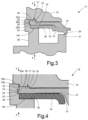
- the diaphragm valve arrangement 1c according to Fig. 3 differs from the diaphragm valve arrangement 1b according to Fig. 2 only in that the annular groove or the receiving space 26 in the axial projection 22 of the housing base 20 is formed rectangularly from an axially parallel surface 24 and two parallel, radially circumferential surfaces 25a, 25b, into which the elastic material 28a of the sealing bead 28 is displaced without completely filling the receiving space 26.
- An additional axial and radial sealing arrangement is formed by the receiving space 26 in conjunction with the elastic material 28a displaced therein.
- An additional sealing arrangement on a diaphragm valve arrangement 1d can also be formed by a circumferential inclined surface 23a on the annular, axial projection 22 of the lower housing part 20 and a gap 26b as a receiving space between the annular, axial projection 22 on the lower housing part 20 and the upper housing part 16, into which displaced elastic material 28a can pass without completely filling the gap 26b.
- two additional sealing arrangements are therefore formed at an axial distance from one another, namely the receiving space 26 and the gap 26b.
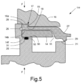
- the diaphragm valve arrangement 1e according to Fig. 5 differs from the diaphragm valve arrangements according to the Figures 2 to 4 in that the sealing bead 28 with rectangular cross-section is arranged on the valve membrane 27 in the annular groove 17, formed by the axially parallel surface 18 and the radial surface 19 on the upper housing part 16 and the annular axial projection 22, and has the same dimensions as the annular groove 17 except for tolerance differences.
- the upper housing part 16 has an axially inwardly projecting annular bead 16a in its groove-related radial surface 19, while the disc 14a supporting the valve membrane 27 is provided with an axially outwardly pointing annular bead 14b.
- elastic material of the sealing bead 28 is displaced into a circumferential groove in the projection 22 forming a receiving space 26 for the displaced elastic material, thereby forming a first additional sealing arrangement.
- an annular groove 31 for receiving an O-ring 32 is arranged in the lower housing part 20 in the region of the support surface 30 for the disc 14a supporting the valve membrane 27, thereby forming a second, additional radial sealing arrangement.
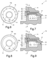
- a coating 36 made of LSR silicone rubber or rubber is injection-molded or vulcanized onto the disc 14 supporting the valve diaphragm 27.
- the injection-molded or vulcanized coating 36 made of LSR silicone rubber or rubber rests on a support surface 33 of the lower housing part 20 and seals the disc 14 axially and radially against the annular axial projection 22 of the lower housing part 20.
- the embodiment of the diaphragm valve arrangements 1g according to the Figures 8 and 9 differs from the embodiments according to the Figures 6 and 7 in that no axial bores 35 are formed in the disc 14 and that a sprue opening 34a is arranged radially inwardly, whereby the injected or vulcanized coating 36a made of LSR silicone rubber or rubber can be made comparatively narrower.
- the embodiment of the diaphragm valve arrangements 1h according to the Figures 10 to 12 differs from the diaphragm valve arrangements according to the Figures 6 to 9 in that the diameter of the radial outer surface 14g of the disc 14c supporting the valve membrane 27 is smaller than the inner diameter of the annular axial projection 22 on the lower housing part 20.
- a seal 36b is injection-molded or vulcanized onto the radial outer surface 14g of the disc 14c via a sprue opening 34b.
- the seal 36b consists of LSR silicone rubber or rubber and fills the annular space between the disc 14c, the valve membrane 27, the annular, radial projection 22 on the lower housing part 20 and the support surface 33 for the disc 14c supporting the valve membrane 27 in such a way that an additional axial and radial sealing arrangement is formed.
- the seal 36b made of silicone rubber or rubber, which is injection-molded radially on the outside of the disc 14c, can have two annular beads 36c, 36d pointing in opposite axial directions, which are pressed into correspondingly assigned receiving grooves in a sealing manner when the upper housing part 16 and the lower housing part 20 are assembled.
- the embodiment of the diaphragm valve arrangements 1i, 1j according to the Figures 13 and 14 differ from the embodiment according to Fig. 5 only in that a radial annular groove 31a, 31b for receiving an O-ring 32a is formed in the outer circumference of the disc 14a supporting the valve membrane 27.
- This O-ring 32a serves to axially and radially seal the disc 14a supporting the valve membrane 27 against the annular axial projection 22 on the housing base 20 in the axial direction.
- the annular groove 31a in the disc 14a has a rectangular cross-section, while the annular groove 31b in the embodiment according to Fig. 14
- the sealing bead 28 of the valve membrane 27 is, as in the embodiment according to Fig. 5 by the axially aligned annular bead 14b on the Disc 14a and the axially aligned annular bead 16a on the radial surface 19 of the upper housing part 16 are sealed in the radial direction.
- the elastic material displaced by the mutual bracing of the upper housing part 16 relative to the lower housing part 20 by means of the clamping force F reaches, as in the embodiment according to Fig. 5 , into the circumferential groove 26 which is formed in the annular axial projection 22 of the housing base 20.
- the embodiment of the diaphragm valve arrangements 1k, 1l, 1m, 1n according to the Figures 15 to 18 differ from the embodiments of diaphragm valve arrangements 1f, 1g according to the Figures 6 to 9 by the fact that according to Fig. 15 an adhesive layer 36e is arranged as a sealing means between the support surface 30 on the housing base 20 and the complementary annular surface 14f on the disc 14 supporting the valve membrane 27.
- this sealing means 36f is arranged between the radial outer surface 14g of the disc 14 supporting the valve membrane 27 and the annular axial projection 22 of the housing lower part 20.
- the sealing means 36g is L-shaped in cross-section and is arranged on the disc 14 supporting the valve membrane 27 in the region of the support surface 30 on the housing lower part 20 and the annular radial projection 22 of the housing lower part 20.
- the sealing means 36h is arranged in a C-shape, as seen in cross section, on all sides of the radially outer edge region of the disc 14 supporting the valve membrane 27.
- the sealant can be used in all examples mentioned according to the Figures 15 to 18 consist of an adhesive or a sealant enclosed in microcapsules or of a liquid, curable but elastic sealant, which form further additional sealing arrangements.
Landscapes
- Engineering & Computer Science (AREA)
- Physics & Mathematics (AREA)
- Fluid Mechanics (AREA)
- Mechanical Engineering (AREA)
- Transportation (AREA)
- Electromagnetism (AREA)
- General Engineering & Computer Science (AREA)
- Valve Housings (AREA)
- Lift Valve (AREA)
- Diaphragms And Bellows (AREA)
Description
- Die Erfindung betrifft eine Membranventilanordnung, beispielsweise in einer Ventileinrichtung eines Anti-Blockiersystems eines Kraftfahrzeugs, aufweisend eine aus einem elastischen Werkstoff bestehende scheibenförmige Ventilmembran sowie eine Scheibe mit einer zentrischen Durchbrechung, wobei die Ventilmembran mit einer ihrer beiden Seiten auf der Scheibe angeordnet ist, wobei die Ventilmembran an ihrer scheibenfernen Seite radial außen einen umlaufenden Dichtungswulst aufweist, wobei die Scheibe zusammen mit der Ventilmembran zwischen einem Gehäuseoberteil und einem Gehäuseunterteil der Membranventilanordnung angeordnet ist, und bei dem der Dichtungswulst zwischen dem Gehäuseoberteil und dem Gehäuseunterteil eingespannt ist.
- Eine derartige Membranventilanordnung ist aus der
DE 21 36 446 A1 bekannt. Der Dichtungswulst ist dabei in einer von einem Gehäuseoberteil und einem Gehäuseunterteil gebildeten Ringnut aufgenommen. Die Dichtungsmembran wird dabei zwischen dem Gehäuseoberteil und dem Gehäuseunterteil bis zu ihrem äußeren Rand von einer Scheibe unterstützt. Der Dichtungswulst der Dichtungsmembran ist auf der von der Scheibe abgewandten Seite ausgebildet und füllt die Ringnut vollständig aus. Die Bearbeitungstoleranzen bei der Herstellung der Ringnut führen dazu, dass der Dichtungswulst zwar in der gewünschten Weise in der Ringnut mit einer vorgegebenen Klemmkraft eingespannt ist, welche für eine dauerhafte Dichtwirkung genau richtig ist und nicht zu einer Verhärtung des elastischen Werkstoffs der Dichtungsmembran führt, jedoch kann auch der Fall eintreten, dass die Dichtwirkung nicht ausreicht, oder dass der Dichtungswulst zu stark durch die Klemmkraft gepresst wird und im Dauerbetrieb eine die Dichtungsmembran beschädigende Verhärtung erleidet. -
WO2010/012425 betrifft ein Membranventil mit einer Elastomermembrane zur Betätigung eines Verschlussgliedes eines Ventilsitzes, welche über eine außenradiale Dichtwulst zwischen einem Ventilgehäuse und einem Gehäusedeckel angeordnet ist und durch eine seitens Gehäusedeckel ausgeformte Steuerdruckkammer beaufschlagbar ist, welche mit einer gewölbten Stützkontur versehen ist, an der die obere Membranfläche der Elastomermembrane im geöffneten Zustand des Verschlussgliedes flächig zur Anlage kommt. -
EP1408389 betrifft ein Drucksteuerventil, welches ein Fluiddruck auf der Seite des Abwärtsfluss das gleiche als der Fluiddruck auf der Seite des Aufwärtsfluss hält. -
DE2713599 betrifft Strömungsmittelpumpen und insbesondere mit einer flexiblen Membran arbeitende Pumpen, welche entweder Flüssigkeiten oder Gase wirksam zu fördern vermögen. -
DE 19638965 betrifft ein fluidbetätigtes Membranventil, bei welchem innerhalb eines Gehäuses mindestens ein kreisrunder Ventilsitz angeordnet ist, welcher von einem membranartigen Betätigungselement vom Ventilsitz öffnend oder auf denselben schliessend betätigbar ist. - Vor diesem Hintergrund liegt der Erfindung die Aufgabe zugrunde, eine Membranventilanordnung vorzuschlagen, bei der die Dichtwirkung im Bereich des Dichtungswulstes weitgehend unabhängig von Fertigungstoleranzen und der wirkenden Klemmkraft verbessert ist.
- Gelöst wird diese Aufgabe mit einer Membranventilanordnung mit den Merkmalen des Anspruchs 1. Der Schutzbereich des Patents soll mit Unterstützung des Wortlauts des Anspruchs entschieden werden.
- Demnach geht die Erfindung aus von einer Membranventilanordnung, beispielsweise in einer Ventileinrichtung eines Anti-Blockiersystems eines Kraftfahrzeugs, aufweisend eine aus einem elastischen Werkstoff bestehende scheibenförmige Ventilmembran sowie eine Scheibe mit einer zentrischen Durchbrechung, wobei die Ventilmembran mit einer ihrer beiden Seiten auf der Scheibe angeordnet ist, wobei die Ventilmembran an ihrer scheibenfernen Seite radial außen einen umlaufenden Dichtungswulst aufweist, wobei die Scheibe zusammen mit der Ventilmembran zwischen einem Gehäuseoberteil und einem Gehäuseunterteil der Membranventilanordnung angeordnet ist, und bei dem der Dichtungswulst zwischen dem Gehäuseoberteil und dem Gehäuseunterteil eingespannt ist. Bei dieser Membranventilanordnung ist zur Lösung der gestellten Aufgabe vorgesehen, dass am Gehäuseoberteil und/oder am Gehäuseunterteil im Bereich des Dichtungswulstes und/oder im radial äußeren Randbereich der die Ventilmembran unterstützenden Scheibe zusätzliche Dichtungsanordnungen vorhanden sind.
- Die zusätzlichen Dichtungsanordnungen sind so gestaltet, dass deren Dichtwirkung weitgehend unabhängig von Fertigungstoleranzen und der wirkenden Klemmkraft zwischen dem Gehäuseoberteil und dem Gehäuseunterteil ist.
- Gemäß einer Beispielerklärung dieses Konstruktionsprinzips kann vorgesehen sein, dass der Dichtungswulst der Ventilmembran in einer axialen Ringnut aufgenommen ist, welche durch einen axialen Absatz im Gehäuseoberteil und einem diesen radial umfassenden, ringförmigen axialen Vorsprung des Gehäuseunterteils gebildet ist, wobei diese axiale Ringnut so bemessen ist, dass der beim Verspannen des Gehäuseoberteils gegen das Gehäuseunterteil verdrängte elastische Werkstoff der Ventilmembran in wenigstens einen dafür bestimmten Aufnahmeraum der Ringnut gelangt, und wobei der wenigstens eine Aufnahmeraum zusammen mit dem verdrängten Werkstoff die zusätzliche Dichtungsanordnung bildet. Bei dem Aufnahmeraum handelt es sich bevorzugt um einen solchen Teil der Ringnut, welcher im unbelasteten Fall, also bei noch nicht vollständig zusammengefügten Gehäuseunterteil und Gehäuseoberteil, von dem Dichtungswulst der Ventilmembran nicht ausgefüllt wird.
- An dieser Stelle sei angemerkt, dass bei der gerade genannten sowie allen noch zu beschreibenden Ausführungsformen der ringförmige, axiale Vorsprung des Gehäuseunterteils durch eine kreisförmige Ausnehmung in der gehäuseoberteilnahen Stirnseite des Gehäuseunterteils erzeugt sein kann, ohne dass darauf jeweils gesondert hingewiesen wird.
- Gemäß einer exemplarischen Gestaltung kann vorgesehen sein, dass die Ringnut wenigstens eine axiale Schrägfläche sowie eine Radialfläche aufweist, dass die Ringnut im Bereich der Radialfläche einen Aufnahmeraum bildet, welcher ohne axiale Krafteinwirkung auf das Gehäuseoberteils und/oder das Gehäuseunterteil von dem Dichtungswulst nicht ausgefüllt ist, und dass nach dem Verspannen des Gehäuseoberteils gegen das Gehäuseunterteil in den Aufnahmeraum verdrängter elastischer Werkstoff des Dichtungswulstes der Ventilmembran angeordnet ist, wobei der Aufnahmeraum und der dort hinein verdrängte Werkstoff des Dichtungswulstes die zusätzliche axiale Dichtungsanordnung bilden.
- Erfindungsgemäß kann vorgesehen sein, dass in dem ringförmigen axialen Vorsprung des Gehäuseunterteils im Bereich des Dichtungswulstes ein Aufnahmeraum durch eine radiale Umfangsnut ausgebildet ist, welche beim Verspannen des Gehäuseoberteils gegen das Gehäuseunterteil verdrängten elastischen Werkstoff der Ventilmembran aufnimmt und eine zusätzliche, radiale und/oder axiale Dichtungsanordnung bildet.
- Erfindungsgemäß ist auch vorgesehen sein, dass die den Aufnahmeraum bildende radiale Umfangsnut im axialen Vorsprung des Gehäuseunterteils eine umlaufende Schrägfläche, eine umlaufende achsparallele Fläche sowie eine radiale, umlaufende Fläche aufweist, dass an der umlaufenden Schrägfläche eine zusätzliche radiale Dichtwirkung erreicht wird, und dass dieser Aufnahmeraum zusammen mit dem verdrängten Werkstoff des Dichtungswulstes die zusätzliche radiale Dichtungsanordnung bildet.
- Eine Ausführungsbeispiel sieht vor, dass in einem radial äußeren, ringförmigen, axialen Vorsprung der die Ventilmembran unterstützenden Scheibe im Bereich des Dichtungswulstes ein Aufnahmeraum durch eine radiale Umfangsnut gebildet ist, welche beim Verspannen des Gehäuseoberteils gegen das Gehäuseunterteil verdrängten elastischen Werkstoff der Ventilmembran aufnimmt und eine zusätzliche, radiale und/oder axiale Dichtungsanordnung bildet.
- Zusätzlich kann in einem anderen Ausführungsbeispiel zwischen dem Gehäuseoberteil und dem Gehäuseunterteil im Bereich einer Oberseite des Dichtungswulstes ein ringförmiger Spalt als Aufnahmeraum für den beim Verspannen des Gehäuseoberteils gegen das Gehäuseunterteil verdrängten elastischen Werkstoff ausgebildet sein, wobei dieser ringförmige Spalt zusammen mit dem da hinein verdrängten Werkstoff eine zusätzliche radiale Dichtanordnung bildet.
- Ein weitere Ausführungsbeispiel der zusätzlichen Dichtungsanordnung sieht vor, dass die die Ringnut axial begrenzende Radialfläche des Gehäuseoberteils und/oder die der Dichtungsmembran zugewandte Oberfläche der Scheibe einen axial ausgerichteten Ringwulst aufweisen, dass in dem ringförmigen, axialen Vorsprung des Gehäuseunterteils oder in dem ringförmigen, axialen Vorsprung der Scheibe eine Umfangsnut als Aufnahmeraum für den beim Verspannen des Gehäuseoberteils gegen das Gehäuseunterteil verdrängten elastischen Werkstoff ausgebildet ist, und dass der durch die Umfangsnut gebildete Aufnahmeraum zusammen mit dem wenigstens einen Ringwulst eine zusätzliche axiale Dichtungsanordnung bildet.
- Weiter kann in einem anderen Ausführungsbeispiel vorgesehen sein, dass das Gehäuseunterteil eine ringförmige, radiale Auflagefläche und die die Ventilmembran unterstützende Scheibe eine dazu komplementäre Ringfläche aufweisen, und dass in der Auflagefläche des Gehäuseunterteils und/oder in der Ringfläche der Scheibe eine Ringnut zur Aufnahme eines O-Rings angeordnet ist, und wobei der O-Ring in der Ringnut eine zusätzliche axiale Dichtungsanordnung bildet.
- Eine weitere Möglichkeit, eine zusätzliche Dichtungsanordnung in der Membranventilanordnung zu bilden, kann darin bestehen, dass das Gehäuseunterteil eine ringförmige, radiale Auflagefläche für die die Ventilmembran unterstützende Scheibe aufweist, dass diese Auflagefläche des Gehäuseunterteils oder eine dieser Auflagefläche zugewandte, komplementäre Ringfläche der die Ventilmembran unterstützende Scheibe mit einer angespritzten Beschichtung aus Silikonkautschuk oder einer anvulkanisierten Beschichtung aus Gummi versehen ist, wobei die an die Auflagefläche des Gehäuseunterteils oder an die komplementäre Ringfläche der Scheibe angespritzte Beschichtung aus Silikonkautschuk oder die anvulkanisierte Beschichtung aus Gummi eine zusätzliche axiale Dichtungsanordnung bildet.
- Eine andere Bauform der zusätzlichen Dichtungsanordnung in der Membranventilanordnung sieht vor, dass der Außendurchmesser der die Ventilmembran unterstützenden Scheibe kleiner ist als der Innendurchmesser des ringförmigen axialen Vorsprungs des Gehäuseunterteils, und dass der hierdurch gebildete Ringraum zwischen der Scheibe und dem Vorsprung durch eine an die radiale Außenfläche der Scheibe angespritzte Dichtung aus Silikonkautschuk oder eine an die radiale Außenfläche anvulkanisierte Dichtung aus Gummi ausgefüllt ist, wobei die an die radiale Außenfläche der Scheibe angespritzte Dichtung eine zusätzliche axiale Dichtungsanordnung bildet.
- Ein weitere Ausführungsbeispiel der zusätzlichen axialen Dichtungsanordnung kann darin bestehen, dass im Außenumfang der die Ventilmembran unterstützenden Scheibe eine Umfangsnut zur Aufnahme eines O-Rings ausgebildet ist, wobei die Umfangsnut mit dem O-Ring eine zusätzliche, axiale Dichtungsanordnung bildet. Hierbei kann vorgesehen sein, dass die Umfangsnut einen rechteckigen Querschnitt oder dreieckigen Querschnitt aufweist.
- Eine weitere Möglichkeit, eine Membranventilanordnung auszubilden, kann darin bestehen, dass die die Ventilmembran unterstützende Scheibe gegenüber dem Gehäuseunterteil durch einen Klebstoff als Dichtungsmittel oder durch ein in Mikrokapseln eingeschlossenes Dichtungsmittel oder durch ein flüssiges Dichtungsmittel abgedichtet ist, wobei das Dichtungsmittel eine zusätzliche axiale und/oder radiale Dichtungsanordnung bildet.
- Hierbei kann vorgesehen sein, dass das Dichtungsmittel wenigstens zwischen einer ringförmigen, radialen Auflagefläche am Gehäuseunterteil für die die Ventilmembran unterstützende Scheibe und einer dieser Auflagefläche zugewandten, komplementären Ringfläche der Scheibe angeordnet ist.
- Abweichend davon kann vorgesehen sein, dass das Dichtungsmittel zwischen der radialen Außenfläche der die Ventilmembran unterstützenden Scheibe und einer radialen Innenoberfläche des ringförmigen axialen Vorsprungs des Gehäuseunterteils angeordnet ist.
- Weiter kann vorgesehen sein, dass das Dichtungsmittel im Querschnitt L-förmig zwischen der radialen Außenfläche der die Ventilmembran unterstützenden Scheibe und der radialen Innenoberfläche des ringförmigen axialen Vorsprungs des Gehäuseunterteils sowie zwischen der ringförmigen, radialen Auflagefläche am Gehäuseunterteil für die die Ventilmembran unterstützende Scheibe und einer dieser Auflagefläche zugewandten, komplementären Ringfläche der Scheibe angeordnet ist.
- Schließlich kann in diesem Zusammenhang vorgesehen sein, dass das Dichtungsmittel im Querschnitt C-förmig an dem radial äußeren Rand der die Ventilmembran unterstützenden Scheibe angeordnet ist.
- Eine weitere Möglichkeit, eine zusätzliche Dichtungsanordnung zu verwirklichen, kann darin bestehen, dass die die Ventilmembran unterstützende Scheibe mit dichtendem radialem Presssitz am Gehäuseunterteil angeordnet ist, wobei der Presssitz eine zusätzliche axiale Dichtungsanordnung bildet.
- Schließlich kann vorgesehen sein, dass die die Ventilmembran unterstützende Scheibe einen ringförmigen, den Dichtungswulst an der Ventilmembran radial einfassenden axialen Vorsprung aufweist, und dass die Scheibe einschließlich ihres ringförmigen axialen Vorsprungs mit dichtendem radialem Presssitz am Gehäuseunterteil angeordnet ist, und dadurch eine zusätzliche axiale Dichtungsanordnung bildet.
- Die Erfindung wird nachstehend anhand mehrerer Ausführungsbeispiele von zusätzlichen Dichtungsanordnungen weiter erläutert. In der beigefügten Zeichnung zeigen die
Figuren 1 bis 4 vier verschiedene Ausführungsbeispiele von zusätzlichen Dichtungsanordnungen im Bereich des Dichtungswulstes an der Dichtungsmembran, und dieFiguren 5 bis 20 zusätzliche Dichtungsanordnungen im Bereich einer eine Ventilmembran unterstützenden Scheibe, wobei die Ausführungsbeispiele vonFiguren 6 bis 11 nicht zu der Erfindung gemäß dem Hauptanspruch 1 gehören. - In den Figuren ist von einer Membranventilanordnung in einer Ventileinrichtung eines Antiblockiersystems nur ein Ausschnitt mit den erfindungsgemäßen, zusätzlichen Dichtungsanordnungen dargestellt, wobei gleiche Teile mit denselben Bezugsziffern bezeichnet sind.
- Die in
Fig. 1 dargestellte Membranventilanordnung 1a weist ein Gehäuseoberteil 2 und ein Gehäuseunterteil 6 auf, welche unter radial äußeres Einklemmen einer Ventilmembran 10 und einer die Ventilmembran 10 axial unterstützenden Scheibe 14 zusammengefügt sind. Im Klemmbereich ist durch eine axiale Schrägfläche 4 und eine Radialfläche 4a am Gehäuseoberteil 2 sowie eine axiale Ringfläche 9 an einem ringförmigen, axialen Vorsprung 8 des Gehäuseunterteils 6 eine Ringnut 3 ausgebildet. Das Gehäuseunterteil 6 weist ferner radial benachbart zu einer Mittelachse 13 der Membranventilanordnung 1a einen Ventilsitz 7 für eine an der Ventilmembran 10 ausgebildete Dichtlippe 12 auf. - An der Ventilmembran 10 ist radial außen ein Dichtungswulst 11 ausgebildet, der in der durch die axiale Schrägfläche 4, die Radialfläche 4a und die Ringfläche 9 gebildete axiale Ringnut 3 aufgenommen ist. Hierbei ist diese Ringnut 3 so bemessen, dass unterhalb der Radialfläche 4a des Gehäuseoberteils 2 ein Aufnahmeraum 5 vorhanden ist, in welchem bei noch nicht endgültig zusammengefügten Gehäuseteilen 2, 6 kein Material des Dichtungswulstes 11 vorhanden ist.
- Axial zwischen der Ventilmembran 10 und dem Gehäuseunterteil 6 ist die die Ventilmembran 10 unterstützende Scheibe 14 angeordnet, welche eine zur Dichtlippe 12 der Ventilmembran 10 benachbarte axiale Durchbrechung 15 aufweist. Diese Scheibe 14 liegt mit ihrer komplementären Ringfläche 14 f auf einer ringförmigen Auflagefläche 30 des Gehäuseunterteils 6 axial auf.
- Sobald das Gehäuseoberteil 2 und das Gehäuseunterteil 6 mit einer Klemmkraft F zusammengefügt und dabei gegeneinander verspannt werden, wird der ursprünglich im Axialschnitt weitgehend rechteckig ausgebildete Dichtungswulst 11 in der aus der axialen Schrägfläche 4, der Radialfläche 4a und der Ringfläche 9 am ringförmigen, axialen Vorsprung 8 gebildeten Ringnut 3 radial zusammengedrückt. Hierbei wird Material des Dichtungswulstes 11 in Richtung des Aufnahmeraumes 5 gedrückt, der durch den verdrängten elastischen Werkstoff 11a erkennbar teilweise ausgefüllt ist.
- Im Vergleich zum eingangs erwähnten Stand der Technik, der eine rechteckige Ringnut zur Aufnahme eines rechteckigen Dichtungswulstes mit gleichem Querschnitt an der Ventilmembran 10 zeigt, ist bei der Ausführungsform gemäß
Fig. 1 eine zusätzliche Dichtungsanordnung durch die Ringnut 3 aus der axialen Schrägfläche 4 und der Radialfläche 4a im Gehäuseoberteil 2 sowie die Ringfläche 9 am ringförmigen, axialen Vorsprung 8 des Gehäuseunterteils 6 in Verbindung mit dem plastisch verformten Dichtungswulst 11 und dem in den Aufnahmeraum 5 verdrängten elastischen Werkstoff 11a gebildet. Hierbei ist der Aufnahmeraum 5 so bemessen ist, dass er auch unter ungünstigen Toleranzbedingungen nicht vollständig durch den verdrängten elastischen Werkstoff 11a des Dichtungswulst 11 ausgefüllt ist. Hierdurch wirken auf den Dichtungswulst 11 keine zu hohen Klemmkräfte F, die andernfalls zu einer nachteiligen Verhärtung des elastischen Werkstoffs der Ventilmembran 10 führen könnten. Durch die geschilderte Ausbildung des Aufnahmeraumes 5 in der Ringnut 3 und durch den dort hinein gedrückten elastischen Werkstoff 11a des Dichtungswulstes 11 ist eine axiale Verlängerung der wirksamen Dichtfläche des Dichtungswulstes 11 vorteilhaft erreicht worden, wodurch eine zusätzliche axiale Dichtungsanordnung gebildet ist, welche zu einer insgesamt verbesserten Abdichtung führt. - Die erfindungsgemäße Ausführungsform gemäß
Fig. 2 zeigt eine ausschnittweise Darstellung einer Membranventilanordnung 1b mit einem Gehäuseoberteil 16 und einem Gehäuseunterteil 20, zwischen denen radial außen ebenfalls eine Ventilmembran 27 und eine diese Ventilmembran 27 unterstützende Scheibe 14 eingeklemmt sind. Das Gehäuseoberteil 16 weist radial innen eine achsparallele Fläche 18 und eine daran anschließende Radialfläche 19 auf. Am Gehäuseunterteil 20 ist radial innen eine axiale Ringfläche 22a ausgebildet, die an einem ringförmigen axialen Vorsprung 22 des Gehäuseunterteils 20 ausgebildet ist. Der axiale Vorsprung 22 kann durch eine kreisförmige Ausnehmung an der gehäuseoberteilnahen Stirnseite des Gehäuseunterteils 20 erzeugt worden sein. Die genannten Flächen 18, 19, 22a bilden zusammen eine rechteckige Ringnut 17. In diese Ringnut 17 ist ein radial außen an der Ventilmembran 27 ausgebildeter Dichtungswulst 28 angeordnet, welcher im Axialschnitt einen rechteckigen Querschnitt aufweist. - Auch diese Ventilmembran 27 liegt radial innen mit einer Dichtlippe 29 auf einem Ventilsitz 21 auf, der radial innen an dem Gehäuseunterteil 20 ausgebildet ist. Die Ventilmembran 27 ist axial durch eine Scheibe 14 abgestützt, welche mit einer Ringfläche 14f auf einer zugeordneten Auflagefläche 30 des Gehäuseunterteils 20 aufliegt. Hierbei sind die Ventilmembran 27 und die Scheibe 14 mittels einer Klemmkraft F zwischen dem Gehäuseunterteil 20 und dem Gehäuseoberteil 16 eingespannt.
- In der erwähnten axialen Ringfläche 22a im axialen Vorsprung 22 des Gehäuseunterteils 20 ist eine durch eine umlaufende Schrägfläche 23, eine achsparallele Fläche 24 und eine radiale, umlaufende Fläche 25 gebildete Umfangsnut ausgebildet, welche so bemessen ist, dass ein beim Verspannen des Gehäuseoberteils 16 gegen das Gehäuseunterteil 20 verdrängter elastischer Werkstoff 28a des Dichtungswulstes 28 einen durch die Umfangsnut gebildeten Aufnahmeraum 26 nur teilweise ausfüllt, wobei der Aufnahmeraum 26 zusammen mit dem verdrängten Werkstoff 28a eine zusätzliche Dichtungsanordnung bildet.
- Die Membranventilanordnung 1c gemäß
Fig. 3 unterscheidet sich von der Membranventilanordnung 1b gemäßFig. 2 nur dadurch, dass die Ringnut beziehungsweise der Aufnahmeraum 26 im axialen Vorsprung 22 des Gehäuseunterteils 20 rechteckig aus einer achsparallelen Fläche 24 und zwei parallelen, radial umlaufenden Flächen 25a, 25b gebildet ist, in die der elastische Werkstoff 28a des Dichtungswulstes 28 verdrängt ist, ohne den Aufnahmeraum 26 vollständig auszufüllen. Durch den Aufnahmeraum 26 in Verbindung in dem da hinein verdrängten elastischen Werkstoff 28a ist eine zusätzliche axiale und radiale Dichtungsanordnung gebildet. - Gemäß
Fig. 4 kann eine zusätzliche Dichtungsanordnung an einer Membranventilanordnung 1d auch durch eine umlaufende Schrägfläche 23a an dem ringförmigen, axialen Vorsprung 22 des Gehäuseunterteils 20 und einen Spalt 26b als Aufnahmeraum zwischen dem ringförmigen, axialen Vorsprung 22 am Gehäuseunterteil 20 und dem Gehäuseoberteil 16 gebildet sein, in die verdrängter elastischer Werkstoff 28a gelangen kann, ohne den Spalt 26b vollständig auszufüllen. Bei dieser Membranventilanordnung 1d sind demnach zwei zusätzliche Dichtungsanordnungen mit axialem Abstand voneinander ausgebildet, nämlich der Aufnahmeraum 26 und der Spalt 26b. - Die Membranventilanordnung 1e gemäß
Fig. 5 unterscheidet sich von den Membranventilanordnungen gemäß denFiguren 2 bis 4 dadurch, dass der Dichtungswulst 28 mit rechteckigen Querschnitt an der Ventilmembran 27 in der Ringnut 17, gebildet aus der achsparallelen Fläche 18 und der Radialfläche 19 am Gehäuseoberteil 16 und dem ringförmigen axialen Vorsprung 22, angeordnet ist und bis auf Toleranzunterschiede die gleichen Abmessungen wie die Ringnut 17 aufweist. Um den Bereich der Ventilmembran 27 mit dem Dichtungswulst 28 unter der Einwirkung der Klemmkraft F im erforderlichen Ausmaß zu komprimieren, weist das Gehäuseoberteil 16 in dessen nutbezogenen Radialfläche 19 einen nach axial innen ragenden Ringwulst 16a auf, während die die Ventilmembran 27 unterstützende Scheibe 14a mit einem nach axial außen weisenden Ringwulst 14b versehen ist. Hierdurch wird elastisches Material des Dichtungswulstes 28 in eine einen Aufnahmeraum 26 für den verdrängten elastischen Werkstoff bildenden Umfangsnut im Vorsprung 22 verdrängt, wodurch eine erste zusätzliche Dichtungsanordnung gebildet ist. Des Weiteren ist im Gehäuseunterteil 20 im Bereich der Auflagefläche 30 für die die Ventilmembran 27 unterstützende Scheibe 14a eine Ringnut 31 zur Aufnahme eines O-Rings 32 angeordnet, wodurch eine zweite, zusätzliche radiale Dichtungsanordnung gebildet ist. - Die Ausführungsbeispielen gemäß den
Figuren 6 bis 11 zeigen zusätzliche Dichtungsanordnungen an Membranventilanordnungen 1f, 1g, 1h in Verbindung mit der die Ventilmembran 27 unterstützenden Scheibe 14, 14c, wobei die Ausführungsbeispiele vonFiguren 6 bis 11 nicht zu der Erfindung gemäß dem Hauptanspruch 1 gehören. - Gemäß den
Figuren 6 und 7 ist eine Beschichtung 36 aus LSR-Silikonkautschuk oder aus Gummi an die die Ventilmembran 27 unterstützende Scheibe 14 angespritzt beziehungsweise anvulkanisiert. Das Anspritzen des LSR-Silikonkautschuks (LSR = Liquid Silicone Rubber) erfolgt von einer Angussöffnung 34 aus, wobei zur besseren Haftung an der die Ventilmembran 27 unterstützenden Scheibe 14 mehrere Axialbohrungen 35 gleichmäßig und ringförmig verteilt in der die Ventilmembran 27 unterstützenden Scheibe 14 ausgebildet sind. Die angespritzte oder anvulkanisierte Beschichtung 36 aus LSR-Silikonkautschuk oder aus Gummi liegt auf einer Auflagefläche 33 des Gehäuseunterteils 20 auf und dichtet die Scheibe 14 axial und radial gegenüber dem ringförmigen axialen Vorsprung 22 des Gehäuseunterteils 20 ab. - Das Ausführungsbeispiel der Membranventilanordnungen 1g gemäß den
Figuren 8 und 9 unterscheidet sich von den Ausführungsbeispielen gemäß denFiguren 6 und 7 dadurch, dass in der Scheibe 14 keine Axialbohrungen 35 ausgebildet sind, und dass eine Angussöffnung 34a radial nach innen verlagert angeordnet ist, wodurch sich die angespritzte oder anvulkanisierte Beschichtung 36a aus LSR-Silikonkautschuk oder aus Gummi vergleichsweise schmaler ausführen lässt. - Das Ausführungsbeispiel der Membranventilanordnungen 1h gemäß den
Figuren 10 bis 12 unterscheidet sich von den der Membranventilanordnungen gemäß denFiguren 6 bis 9 dadurch, dass der Durchmesser der radialen Außenfläche 14g der die Ventilmembran 27 unterstützenden Scheibe 14c kleiner ist als der Innendurchmesser des ringförmigen axialen Vorsprungs 22 am Gehäuseunterteil 20. An die radiale Außenfläche 14g der Scheibe 14c ist über eine Angussöffnung 34b eine Dichtung 36b angespritzt oder anvulkanisiert, die aus LSR-Silikonkautschuk oder aus Gummi besteht und den Ringraum zwischen der Scheibe 14c, der Ventilmembran 27, dem ringförmigen, radialen Vorsprung 22 am Gehäuseunterteil 20 und der Auflagefläche 33 für die die Ventilmembran 27 unterstützende Scheibe 14c so ausfüllt, dass eine zusätzliche axiale und radiale Dichtungsanordnung gebildet ist. - Wie die Längsschnittansicht gemäß
Fig. 12 veranschaulicht, kann die radial außen an der Scheibe 14c angespritzte Dichtung 36b aus Silikonkautschuk oder Gummi zwei in entgegengesetzte axiale Richtungen weisende Ringwülste 36c, 36d aufweisen, die beim Zusammensetzen von Gehäuseoberteil 16 und Gehäuseunterteil 20 abdichtend beispielsweise in entsprechend zugeordnete Aufnahmenuten eingepresst werden. - Das Ausführungsbeispiel der Membranventilanordnungen 1i, 1j gemäß den
Figuren 13 und 14 unterscheiden sich von dem Ausführungsbeispiel gemäßFig. 5 nur dadurch, dass im Außenumfang der die Ventilmembran 27 unterstützenden Scheibe 14a jeweils eine radiale Ringnut 31a, 31b zur Aufnahme eines O-Rings 32a ausgebildet ist. Dieser O-Ring 32a dient zur axialen und radialen Abdichtung der die Ventilmembran 27 unterstützenden Scheibe 14a gegenüber dem ringförmigen axialen Vorsprung 22 am Gehäuseunterteil 20 in axialer Richtung. - Gemäß
Fig. 13 hat die Ringnut 31a in der Scheibe 14a einen Rechteckquerschnitt, während die Ringnut 31b bei dem Ausführungsbeispiel gemäßFig. 14 einen Dreieckquerschnitt aufweist. Der Dichtungswulst 28 der Ventilmembran 27 ist wie bei dem Ausführungsbeispiel gemäßFig. 5 durch den axial ausgerichteten Ringwulst 14b an der Scheibe 14a und den axial ausgerichteten Ringwulst 16a an der Radialfläche 19 des Gehäuseoberteils 16 in radialer Richtung abgedichtet. Der durch das gegenseitige Verspannen des Gehäuseoberteils 16 gegenüber dem Gehäuseunterteil 20 mittels der Klemmkraft F verdrängte elastische Werkstoff gelangt, wie bei dem Ausführungsbeispiel gemäßFig. 5 , in die Umfangsnut 26, welche in dem ringförmigen axialen Vorsprung 22 des Gehäuseunterteils 20 ausgebildet ist. - Das Ausführungsbeispiel der Membranventilanordnungen 1k, 1l, 1m, 1n gemäß den
Figuren 15 bis 18 unterscheiden sich von den Ausführungsbeispielen Membranventilanordnungen 1f, 1g gemäß denFiguren 6 bis 9 dadurch, dass gemäßFig. 15 eine Klebstoffschicht 36e als Dichtungsmittel zwischen der Auflagefläche 30 am Gehäuseunterteil 20 und der komplementären Ringfläche 14f an der die Ventilmembran 27 unterstützenden Scheibe 14 angeordnet ist. - Gemäß der in
Fig. 16 gezeigten Ausführungsvariante ist dieses Dichtungsmittel 36f zwischen der radialen Außenfläche 14g der die Ventilmembran 27 unterstützenden Scheibe 14 und dem ringförmigen axialen Vorsprung 22 des Gehäuseunterteils 20 angeordnet. - Bei der Ausführungsvariante gemäß
Fig. 17 ist das Dichtungsmittel 36g im Querschnitt gesehen L-förmig ausgebildet und an der die Ventilmembran 27 unterstützenden Scheibe 14 im Bereich der Auflagefläche 30 am Gehäuseunterteil 20 und dem ringförmigen radialen Vorsprung 22 des Gehäuseunterteils 20 angeordnet. - Gemäß der in
Fig. 18 gezeigten Ausführungsvariante ist das Dichtungsmittel 36h im Querschnitt gesehen C-förmig auf dem radial äußeren Randbereich der die Ventilmembran 27 abstützenden Scheibe 14 allseitig angeordnet. - Das Dichtungsmittel kann in allen genannten Beispielen gemäß den
Figuren 15 bis 18 aus einem Klebstoff oder aus einem in Mikrokapseln eingeschlossenen Dichtungsmittel oder aus einem flüssigen, aushärtbaren, aber elastisch bleibenden Dichtungsmittel bestehen, die weitere zusätzliche Dichtungsanordnungen bilden. - Schließlich ist es auch noch möglich, weitere zusätzliche Dichtungsanordnungen an Membranventilanordnungen 1o, 1p gemäß den
Figuren 19 und 20 auszubilden, die gemäßFig. 19 darin besteht, dass die die Ventilmembran 27 unterstützende Scheibe 14a mit einem dichtenden Presssitz 37 in den ringförmigen radialen Vorsprung 22 des Gehäuseunterteils 20 eingepasst ist. Ähnlich kann gemäßFig. 20 die die Ventilmembran 27 unterstützende Scheibe 14d einen ringförmigen axialen Vorsprung 14e aufweisen, der mit einem dichtenden Presssitz 37a in den ringförmigen radialen Vorsprung 22 des Gehäuseunterteils 20 eingepasst ist. - Alle dargestellten und beschriebenen Ausführungsformen bzw. Ausführungsbeispielen gemäß den
Figuren 1 bis 20 beruhen auf der Überlegung, dass sich durch zusätzliche Dichtungsanordnungen zwischen dem Gehäuseoberteil 2, 16 und dem Gehäuseunterteil 6, 20 die Klemmkraft F besser kontrollieren und einstellen lässt. Hierdurch wird gewährleistet, dass der Dichtungswulst 11, 28 nicht durch eine zu hohe Klemmkraft F beschädigt wird, wobei dennoch die Dichtwirkung zwischen dem Gehäuseoberteil 2, 16 und dem Gehäuseunterteil 6, 20 verbessert ist. -
- 1a -1p
- Membranventilanordnung
- 2
- Gehäuseoberteil
- 3
- Ringnut
- 4
- Axiale Schrägfläche am Gehäuseoberteil 2
- 4a
- Radialfläche am Gehäuseoberteil 2
- 5
- Aufnahmeraum
- 6
- Gehäuseunterteil
- 7
- Ventilsitz am Gehäuseunterteil 6
- 8
- Ringförmiger axialer Vorsprung am Gehäuseunterteil 6, gebildet beispielsweise durch eine stirnseitige Einsenkung im Gehäuseunterteil 6
- 9
- Axiale Ringfläche am Vorsprung 8 des Gehäuseunterteils 6
- 10
- Ventilmembran
- 11
- Dichtungswulst an der Ventilmembran 11
- 11a
- Verdrängter, elastischer Werkstoff des Dichtungswulstes 11
- 12
- Dichtlippe an der Ventilmembran 10
- 13
- Mittelachse der Membranventilanordnung
- 14
- Die Ventilmembran unterstützende Scheibe
- 14a
- Die Ventilmembran unterstützende Scheibe
- 14b
- Ringwulst an der Scheibe 14a
- 14c
- Die Ventilmembran unterstützende Scheibe
- 14d
- Die Ventilmembran unterstützende Scheibe
- 14e
- Ringförmiger axialer Vorsprung der Scheibe 14d
- 14f
- Komplementäre Ringfläche der Scheibe 14, 14a, 14c, 14d
- 14g
- Radiale Außenfläche der Scheibe14, 14a, 14c, 14d
- 15
- Zentrische Durchbrechung in der Scheibe 14, 14a, 14c, 14d
- 16
- Gehäuseoberteil
- 16a
- Ringwulst am Gehäuseoberteil 16
- 17
- Ringnut
- 18
- Achsparallele Fläche am Gehäuseoberteil 16
- 19
- Radialfläche am Gehäuseoberteil 16
- 20
- Gehäuseunterteil
- 21
- Ventilsitz am Gehäuseunterteil 20
- 22
- Ringförmiger, axialer Vorsprung am Gehäuseunterteil 20, gebildet beispielsweise durch eine stirnseitige Einsenkung im Gehäuseunterteil 20
- 22a
- Axiale Ringfläche am Gehäuseunterteil 20
- 23
- Umlaufende Schrägfläche am Gehäuseunterteil 20
- 23a
- Umlaufende Schrägfläche am Gehäuseunterteil 20
- 24
- Achsparallele Fläche am Gehäuseunterteil 20
- 25a
- Erste radial umlaufende Fläche des Aufnahmeraums 26
- 25b
- Zweite radial umlaufende Fläche des Aufnahmeraums 26
- 26
- Umfangsnut bzw. Aufnahmeraum in Vorsprung 22
- 26a
- Umfangsnut bzw. Aufnahmeraum in Vorsprung 22
- 26b
- Ringförmiger Spalt als Aufnahmeraum
- 27
- Ventilmembran
- 28
- Dichtungswulst an Ventilmembran 27
- 28a
- Verdrängter, elastischer Werkstoff vom Dichtungswulst 28
- 29
- Dichtlippe an Ventilmembran 27
- 30
- Ringförmige Auflagefläche am Gehäuseunterteil 6, 20
- 31a
- Ringnut im Gehäuseunterteil 20 (1. Ausführung)
- 31b
- Ringnut im Gehäuseunterteil 20 (2. Ausführung)
- 32
- O-Ring (1. Ausführung gemäß
Fig. 5 ) - 32a
- O-Ring (2. Ausführung gemäß
Fig. 13 und 14 ) - 33
- Auflagefläche am Gehäuseunterteil 20
- 34
- Angussöffnung (1. Ausführung) in der Scheibe 14
- 34a
- Angussöffnung (2. Ausführung) in der Scheibe 14
- 35
- Axialbohrungen in der Scheibe 14
- 36
- Angespritzte oder anvulkanisierte Beschichtung (1. Ausführung)
- 36a
- Angespritzte oder anvulkanisierte Beschichtung (2. Ausführung)
- 36b
- Angespritzte oder anvulkanisierte Dichtung
- 36c
- Erster Ringwulst an Dichtung 36b
- 36d
- Zweiter Ringwulst an Dichtung 36b
- 36e
- Radiales Dichtungsmittel
- 36f
- Axiales Dichtungsmittel
- 36g
- L-förmiges Dichtungsmittel
- 36h
- C-förmiges Dichtungsmittel
- 37
- Dichtender Presssitz
- 37a
- Dichtender Presssitz
- F
- Klemmkraft
Claims (1)
- Membranventilanordnung (1a, 1b, 1c, 1d, 1e, 1f, 1g, 1h, 1i, 1j, 1k, 11, 1m, 1n, 1o, 1p), beispielsweise in einer Ventileinrichtung eines Anti-Blockiersystems eines Kraftfahrzeugs, aufweisend eine aus einem elastischen Werkstoff bestehende scheibenförmige Ventilmembran (10, 27), eine Scheibe (14, 14a, 14c, 14d) mit einer zentrischen Durchbrechung (15), ein Gehäuseoberteil (2, 16) mit einem axialen Absatz und ein Gehäuseunterteil (6, 20) mit einem radial umfassenden, ringförmigen, axialen Vorsprung, wobei in einer gehäuseoberteilnahen Stirnseite des Gehäuseunterteils (6, 20) eine kreisförmige Ausnehmung gebildet ist, wobei die Ventilmembran (10, 27) mit einer ihrer beiden Seiten auf der Scheibe (14, 14a, 14c, 14d) angeordnet ist, wobei die Ventilmembran (10, 27) an ihrer scheibenfernen Seite radial außen einen umlaufenden Dichtungswulst (11, 28) aufweist, wobei die Scheibe (14, 14a, 14c, 14d) zusammen mit der Ventilmembran (10, 27) zwischen dem Gehäuseoberteil (2, 16) und dem Gehäuseunterteil (6, 20) der Membranventilanordnung (1) angeordnet ist, und bei dem der Dichtungswulst (11, 28) zwischen dem Gehäuseoberteil (2, 16) und dem Gehäuseunterteil (6, 20) eingespannt ist, wobei am Gehäuseoberteil (2, 16) und/oder am Gehäuseunterteil (6, 20) im Bereich des Dichtungswulstes (11, 28) und/oder im radial äußeren Randbereich der die Ventilmembran (10, 27) unterstützenden Scheibe (14, 14a, 14c, 14d) wenigstens eine zusätzliche Dichtungsanordnung vorhanden ist, dadurch gekennzeichnet,dass der Dichtungswulst (11, 28) der Ventilmembran (10, 27) in einer axialen Ringnut (3, 17) aufgenommen ist, welche durch den axialen Absatz im Gehäuseoberteil (2, 16) und dem radial umfassenden, ringförmigen, axialen Vorsprung (8, 22) des Gehäuseunterteils (6, 20) gebildet ist, wobei die axiale Ringnut (3, 17) so bemessen ist, dass der beim Verspannen des Gehäuseoberteils (2, 16) gegen das Gehäuseunterteil (6, 20) verdrängte elastische Werkstoff (11a, 28a) der Ventilmembran (10, 27) in wenigstens einen Aufnahmeraum (5, 26, 26a, 26b) der Ringnut (3, 17) gelangt, und wobei der wenigstens eine Aufnahmeraum (5; 26; 26a; 26b) zusammen mit dem verdrängten Werkstoff (11a, 28a) die zusätzliche Dichtungsanordnung bildet, dass der ringförmige, axiale Vorsprung (8, 22) des Gehäuseunterteils (6, 20) durch die kreisförmige Ausnehmung in der gehäuseoberteilnahen Stirnseite des Gehäuseunterteils (6, 20) gebildet ist, dass in dem ringförmigen axialen Vorsprung (22) des Gehäuseunterteils (20) im Bereich des Dichtungswulstes (28) ein Aufnahmeraum (26) durch eine radiale Umfangsnut gebildet ist, welche beim Verspannen des Gehäuseoberteils (16) gegen das Gehäuseunterteil (20) verdrängten elastischen Werkstoff (28a) der Ventilmembran (27) aufnimmt und eine zusätzliche, radiale und/oder axiale Dichtungsanordnung bildet, dass die den Aufnahmeraum (26) bildende radiale Umfangsnut im axialen Vorsprung (22) des Gehäuseunterteils (20) eine umlaufende Schrägfläche (23), eine umlaufende achsparallele Fläche (24) sowie eine radiale, umlaufende Fläche (25) aufweist,dass an der umlaufenden Schrägfläche (23) die zusätzliche radiale Dichtwirkung erreicht wird, und dass der Aufnahmeraum (26) zusammen mit dem verdrängten Werkstoff (28a) des Dichtungswulstes (28) die zusätzliche radiale Dichtungsanordnung bildet.
Applications Claiming Priority (2)
| Application Number | Priority Date | Filing Date | Title |
|---|---|---|---|
| DE102016009402.8A DE102016009402A1 (de) | 2016-08-02 | 2016-08-02 | Membranventilanordnung |
| PCT/EP2017/000858 WO2018024360A1 (de) | 2016-08-02 | 2017-07-17 | Membranventilanordnung |
Publications (2)
| Publication Number | Publication Date |
|---|---|
| EP3494018A1 EP3494018A1 (de) | 2019-06-12 |
| EP3494018B1 true EP3494018B1 (de) | 2025-06-18 |
Family
ID=59383528
Family Applications (1)
| Application Number | Title | Priority Date | Filing Date |
|---|---|---|---|
| EP17742370.4A Active EP3494018B1 (de) | 2016-08-02 | 2017-07-17 | Membranventilanordnung |
Country Status (5)
| Country | Link |
|---|---|
| US (1) | US11117560B2 (de) |
| EP (1) | EP3494018B1 (de) |
| CN (1) | CN109195842B (de) |
| DE (1) | DE102016009402A1 (de) |
| WO (1) | WO2018024360A1 (de) |
Families Citing this family (5)
| Publication number | Priority date | Publication date | Assignee | Title |
|---|---|---|---|---|
| DE102017011607A1 (de) | 2017-12-15 | 2019-06-19 | Wabco Europe Bvba | Membranventilanordnung für eine Druckluftbremsanlage |
| FR3087142B1 (fr) | 2018-10-11 | 2021-04-16 | Ballocchi | Procede de rectification compatible a un assemblage selon une etancheite d'une valeur inferieure a 5.10-9 pa m3.s.-1. sur un montage de deux pieces en fontes vissees |
| JP2021085548A (ja) * | 2019-11-25 | 2021-06-03 | 株式会社不二工機 | パワーエレメント及びこれを用いた膨張弁 |
| CN116201927B (zh) * | 2021-11-30 | 2025-12-16 | 宁波英科特流体控制技术有限公司 | 一种隔膜阀隔膜固定机构及隔膜阀 |
| CN121194910A (zh) | 2023-05-23 | 2025-12-23 | 采埃孚商用车系统欧洲有限公司 | 用于商用车辆的制动控制阀 |
Family Cites Families (12)
| Publication number | Priority date | Publication date | Assignee | Title |
|---|---|---|---|---|
| IT942995B (it) | 1971-07-21 | 1973-04-02 | Westinghouse Bremsen Apparate | Valvola di corsa per sistemi antislittamento per veicoli stradali |
| US4086036A (en) * | 1976-05-17 | 1978-04-25 | Cole-Parmer Instrument Company | Diaphragm pump |
| DE19638965C1 (de) * | 1996-09-12 | 1998-05-07 | Mannesmann Ag | Fluidbetätigtes Membran-Ventil |
| JP4471541B2 (ja) * | 2001-07-18 | 2010-06-02 | 旭有機材工業株式会社 | 定圧レギュレータ |
| JP5064903B2 (ja) * | 2007-06-21 | 2012-10-31 | Ckd株式会社 | 流体制御弁 |
| DE102008028439B3 (de) * | 2008-06-17 | 2009-10-15 | Knorr-Bremse Systeme für Nutzfahrzeuge GmbH | Verfahren zur Herstellung Drucksteuerventilanordnung zur Steuerung eines Fluiddrucks in einer ABS-Bremsanlage eines Fahrzeugs |
| DE102008035372A1 (de) * | 2008-07-30 | 2010-02-11 | Knorr-Bremse Systeme für Schienenfahrzeuge GmbH | Membranenventil, insbesondere für ein ABS- oder Gleitschutzventil |
| CN201439341U (zh) * | 2009-06-28 | 2010-04-21 | 东风汽车股份有限公司 | 降低封闭压力和残留压力的气压调节阀 |
| JP5743744B2 (ja) * | 2011-06-24 | 2015-07-01 | 株式会社不二工機 | ダイアフラム式流体制御弁 |
| DE102012005093A1 (de) * | 2012-03-14 | 2013-09-19 | Festo Ag & Co. Kg | Membranventil |
| DE102014012712A1 (de) * | 2014-08-27 | 2016-03-03 | Wabco Gmbh | Ventileinheit zur Druckmodulation in einer Druckluft-Bremsanlage |
| DE102015016265A1 (de) * | 2015-12-15 | 2017-06-22 | Wabco Europe Bvba | Ventileinheit zur Druckmodulation in einer Druckluft-Bremsanlage |
-
2016
- 2016-08-02 DE DE102016009402.8A patent/DE102016009402A1/de active Pending
-
2017
- 2017-07-17 WO PCT/EP2017/000858 patent/WO2018024360A1/de not_active Ceased
- 2017-07-17 US US16/321,584 patent/US11117560B2/en active Active
- 2017-07-17 CN CN201780032807.5A patent/CN109195842B/zh active Active
- 2017-07-17 EP EP17742370.4A patent/EP3494018B1/de active Active
Also Published As
| Publication number | Publication date |
|---|---|
| WO2018024360A1 (de) | 2018-02-08 |
| CN109195842A (zh) | 2019-01-11 |
| DE102016009402A1 (de) | 2018-02-08 |
| US11117560B2 (en) | 2021-09-14 |
| CN109195842B (zh) | 2021-06-15 |
| US20190344765A1 (en) | 2019-11-14 |
| EP3494018A1 (de) | 2019-06-12 |
Similar Documents
| Publication | Publication Date | Title |
|---|---|---|
| EP3494018B1 (de) | Membranventilanordnung | |
| EP0612537B1 (de) | Rückschlagventil, insbesondere für medizinische Anwendungen der Fluidtechnik | |
| EP2397727B1 (de) | Mehrteiliger Ventilteller | |
| EP2880329B1 (de) | Nehmerzylinder für eine hydraulische ausrückanordnung zur betätigung einer kupplung | |
| EP3978751B1 (de) | Verbundmembran für membranpumpen | |
| EP3433515B1 (de) | Dichtungsanordnung und verfahren zur herstellung einer dichtungsanordnung | |
| DE102013200533B4 (de) | Ventilpatrone | |
| WO2010054900A1 (de) | Rückschlagventil in patronenbauform | |
| EP2554878B1 (de) | Dichtung | |
| EP1137562A1 (de) | Schwingungsdämpfer zur dämpfung von flüssigkeitsschwingungen in einem hydraulischen system | |
| WO2016026949A1 (de) | Dichtungsring zum axialen abdichten von zwei axial relativ zueinander beweglich angeordneten teilen und dichtungssystem mit dem dichtungsring | |
| DE112014004520B4 (de) | Zylindervorrichtung und Dichtelement | |
| DE102015221686A1 (de) | Hydraulisches Gerät mit Anschlussfläche und Ringnut | |
| EP1681498B1 (de) | Dichtung | |
| EP4058680B1 (de) | Radlagereinheit | |
| DE1950381C3 (de) | Dichtungspackung zur Spaltabdichtung gegenüber hydraulischen oder pneumatischen Drücken | |
| WO2010139655A1 (de) | Wellendichtring | |
| DE4311547C2 (de) | Gleitringdichtungsanordnung | |
| EP1043506A1 (de) | Schwenkmotor | |
| EP3842671B1 (de) | Wellendichtung, insbesondere radialwellendichtung, mit wenigstens einem dichtelement | |
| DE102017119644A1 (de) | Geberzylinder für ein Kupplungs- oder Bremssystem mit Dichtelement | |
| DE10240052A1 (de) | Dicht-und Führungsvorrichtung | |
| DE102016211542B4 (de) | Kolben-Zylinder-Anordnung für eine Ausrückeinheit, insbesondere für einen Geberzylinder einer hydraulischen Kupplungsbetätigungseinrichtung | |
| DE3336863A1 (de) | Radialwellendichtring | |
| EP3504467A1 (de) | Dichtungsanordnung und ventilanordnung |
Legal Events
| Date | Code | Title | Description |
|---|---|---|---|
| STAA | Information on the status of an ep patent application or granted ep patent |
Free format text: STATUS: UNKNOWN |
|
| STAA | Information on the status of an ep patent application or granted ep patent |
Free format text: STATUS: THE INTERNATIONAL PUBLICATION HAS BEEN MADE |
|
| PUAI | Public reference made under article 153(3) epc to a published international application that has entered the european phase |
Free format text: ORIGINAL CODE: 0009012 |
|
| STAA | Information on the status of an ep patent application or granted ep patent |
Free format text: STATUS: REQUEST FOR EXAMINATION WAS MADE |
|
| 17P | Request for examination filed |
Effective date: 20190304 |
|
| AK | Designated contracting states |
Kind code of ref document: A1 Designated state(s): AL AT BE BG CH CY CZ DE DK EE ES FI FR GB GR HR HU IE IS IT LI LT LU LV MC MK MT NL NO PL PT RO RS SE SI SK SM TR |
|
| AX | Request for extension of the european patent |
Extension state: BA ME |
|
| DAV | Request for validation of the european patent (deleted) | ||
| DAX | Request for extension of the european patent (deleted) | ||
| STAA | Information on the status of an ep patent application or granted ep patent |
Free format text: STATUS: EXAMINATION IS IN PROGRESS |
|
| 17Q | First examination report despatched |
Effective date: 20200109 |
|
| RAP3 | Party data changed (applicant data changed or rights of an application transferred) |
Owner name: ZF CV SYSTEMS EUROPE BV |
|
| GRAP | Despatch of communication of intention to grant a patent |
Free format text: ORIGINAL CODE: EPIDOSNIGR1 |
|
| STAA | Information on the status of an ep patent application or granted ep patent |
Free format text: STATUS: GRANT OF PATENT IS INTENDED |
|
| INTG | Intention to grant announced |
Effective date: 20250227 |
|
| GRAS | Grant fee paid |
Free format text: ORIGINAL CODE: EPIDOSNIGR3 |
|
| GRAA | (expected) grant |
Free format text: ORIGINAL CODE: 0009210 |
|
| STAA | Information on the status of an ep patent application or granted ep patent |
Free format text: STATUS: THE PATENT HAS BEEN GRANTED |
|
| AK | Designated contracting states |
Kind code of ref document: B1 Designated state(s): AL AT BE BG CH CY CZ DE DK EE ES FI FR GB GR HR HU IE IS IT LI LT LU LV MC MK MT NL NO PL PT RO RS SE SI SK SM TR |
|
| REG | Reference to a national code |
Ref country code: GB Ref legal event code: FG4D Free format text: NOT ENGLISH |
|
| REG | Reference to a national code |
Ref country code: CH Ref legal event code: EP |
|
| REG | Reference to a national code |
Ref country code: DE Ref legal event code: R096 Ref document number: 502017016907 Country of ref document: DE |
|
| REG | Reference to a national code |
Ref country code: CH Ref legal event code: EP |
|
| REG | Reference to a national code |
Ref country code: IE Ref legal event code: FG4D Free format text: LANGUAGE OF EP DOCUMENT: GERMAN |
|
| PGFP | Annual fee paid to national office [announced via postgrant information from national office to epo] |
Ref country code: FR Payment date: 20250623 Year of fee payment: 9 |
|
| PG25 | Lapsed in a contracting state [announced via postgrant information from national office to epo] |
Ref country code: FI Free format text: LAPSE BECAUSE OF FAILURE TO SUBMIT A TRANSLATION OF THE DESCRIPTION OR TO PAY THE FEE WITHIN THE PRESCRIBED TIME-LIMIT Effective date: 20250618 |
|
| PGFP | Annual fee paid to national office [announced via postgrant information from national office to epo] |
Ref country code: DE Payment date: 20250611 Year of fee payment: 9 |
|
| REG | Reference to a national code |
Ref country code: LT Ref legal event code: MG9D |
|
| PG25 | Lapsed in a contracting state [announced via postgrant information from national office to epo] |
Ref country code: GR Free format text: LAPSE BECAUSE OF FAILURE TO SUBMIT A TRANSLATION OF THE DESCRIPTION OR TO PAY THE FEE WITHIN THE PRESCRIBED TIME-LIMIT Effective date: 20250919 Ref country code: NO Free format text: LAPSE BECAUSE OF FAILURE TO SUBMIT A TRANSLATION OF THE DESCRIPTION OR TO PAY THE FEE WITHIN THE PRESCRIBED TIME-LIMIT Effective date: 20250918 |
|
| PG25 | Lapsed in a contracting state [announced via postgrant information from national office to epo] |
Ref country code: BG Free format text: LAPSE BECAUSE OF FAILURE TO SUBMIT A TRANSLATION OF THE DESCRIPTION OR TO PAY THE FEE WITHIN THE PRESCRIBED TIME-LIMIT Effective date: 20250618 |
|
| PGFP | Annual fee paid to national office [announced via postgrant information from national office to epo] |
Ref country code: GB Payment date: 20250703 Year of fee payment: 9 |
|
| PG25 | Lapsed in a contracting state [announced via postgrant information from national office to epo] |
Ref country code: HR Free format text: LAPSE BECAUSE OF FAILURE TO SUBMIT A TRANSLATION OF THE DESCRIPTION OR TO PAY THE FEE WITHIN THE PRESCRIBED TIME-LIMIT Effective date: 20250618 |
|
| PG25 | Lapsed in a contracting state [announced via postgrant information from national office to epo] |
Ref country code: RS Free format text: LAPSE BECAUSE OF FAILURE TO SUBMIT A TRANSLATION OF THE DESCRIPTION OR TO PAY THE FEE WITHIN THE PRESCRIBED TIME-LIMIT Effective date: 20250918 |
|
| REG | Reference to a national code |
Ref country code: NL Ref legal event code: MP Effective date: 20250618 |
|
| PG25 | Lapsed in a contracting state [announced via postgrant information from national office to epo] |
Ref country code: LV Free format text: LAPSE BECAUSE OF FAILURE TO SUBMIT A TRANSLATION OF THE DESCRIPTION OR TO PAY THE FEE WITHIN THE PRESCRIBED TIME-LIMIT Effective date: 20250618 |
|
| PG25 | Lapsed in a contracting state [announced via postgrant information from national office to epo] |
Ref country code: NL Free format text: LAPSE BECAUSE OF FAILURE TO SUBMIT A TRANSLATION OF THE DESCRIPTION OR TO PAY THE FEE WITHIN THE PRESCRIBED TIME-LIMIT Effective date: 20250618 |
|
| PG25 | Lapsed in a contracting state [announced via postgrant information from national office to epo] |
Ref country code: PT Free format text: LAPSE BECAUSE OF FAILURE TO SUBMIT A TRANSLATION OF THE DESCRIPTION OR TO PAY THE FEE WITHIN THE PRESCRIBED TIME-LIMIT Effective date: 20251020 |
|
| PG25 | Lapsed in a contracting state [announced via postgrant information from national office to epo] |
Ref country code: IS Free format text: LAPSE BECAUSE OF FAILURE TO SUBMIT A TRANSLATION OF THE DESCRIPTION OR TO PAY THE FEE WITHIN THE PRESCRIBED TIME-LIMIT Effective date: 20251018 |
|
| PG25 | Lapsed in a contracting state [announced via postgrant information from national office to epo] |
Ref country code: SM Free format text: LAPSE BECAUSE OF FAILURE TO SUBMIT A TRANSLATION OF THE DESCRIPTION OR TO PAY THE FEE WITHIN THE PRESCRIBED TIME-LIMIT Effective date: 20250618 |
|
| PG25 | Lapsed in a contracting state [announced via postgrant information from national office to epo] |
Ref country code: CZ Free format text: LAPSE BECAUSE OF FAILURE TO SUBMIT A TRANSLATION OF THE DESCRIPTION OR TO PAY THE FEE WITHIN THE PRESCRIBED TIME-LIMIT Effective date: 20250618 |
|
| PG25 | Lapsed in a contracting state [announced via postgrant information from national office to epo] |
Ref country code: PL Free format text: LAPSE BECAUSE OF FAILURE TO SUBMIT A TRANSLATION OF THE DESCRIPTION OR TO PAY THE FEE WITHIN THE PRESCRIBED TIME-LIMIT Effective date: 20250618 |
|
| PG25 | Lapsed in a contracting state [announced via postgrant information from national office to epo] |
Ref country code: EE Free format text: LAPSE BECAUSE OF FAILURE TO SUBMIT A TRANSLATION OF THE DESCRIPTION OR TO PAY THE FEE WITHIN THE PRESCRIBED TIME-LIMIT Effective date: 20250618 |
|
| PG25 | Lapsed in a contracting state [announced via postgrant information from national office to epo] |
Ref country code: SK Free format text: LAPSE BECAUSE OF FAILURE TO SUBMIT A TRANSLATION OF THE DESCRIPTION OR TO PAY THE FEE WITHIN THE PRESCRIBED TIME-LIMIT Effective date: 20250618 Ref country code: RO Free format text: LAPSE BECAUSE OF FAILURE TO SUBMIT A TRANSLATION OF THE DESCRIPTION OR TO PAY THE FEE WITHIN THE PRESCRIBED TIME-LIMIT Effective date: 20250618 |
|
| PG25 | Lapsed in a contracting state [announced via postgrant information from national office to epo] |
Ref country code: ES Free format text: LAPSE BECAUSE OF FAILURE TO SUBMIT A TRANSLATION OF THE DESCRIPTION OR TO PAY THE FEE WITHIN THE PRESCRIBED TIME-LIMIT Effective date: 20250618 |
|
| REG | Reference to a national code |
Ref country code: CH Ref legal event code: H13 Free format text: ST27 STATUS EVENT CODE: U-0-0-H10-H13 (AS PROVIDED BY THE NATIONAL OFFICE) Effective date: 20260224 |
|
| PG25 | Lapsed in a contracting state [announced via postgrant information from national office to epo] |
Ref country code: LU Free format text: LAPSE BECAUSE OF NON-PAYMENT OF DUE FEES Effective date: 20250717 |
|
| REG | Reference to a national code |
Ref country code: BE Ref legal event code: MM Effective date: 20250731 |
|
| PG25 | Lapsed in a contracting state [announced via postgrant information from national office to epo] |
Ref country code: MC Free format text: LAPSE BECAUSE OF FAILURE TO SUBMIT A TRANSLATION OF THE DESCRIPTION OR TO PAY THE FEE WITHIN THE PRESCRIBED TIME-LIMIT Effective date: 20250618 |
|
| PG25 | Lapsed in a contracting state [announced via postgrant information from national office to epo] |
Ref country code: DK Free format text: LAPSE BECAUSE OF FAILURE TO SUBMIT A TRANSLATION OF THE DESCRIPTION OR TO PAY THE FEE WITHIN THE PRESCRIBED TIME-LIMIT Effective date: 20250618 |
|
| PG25 | Lapsed in a contracting state [announced via postgrant information from national office to epo] |
Ref country code: BE Free format text: LAPSE BECAUSE OF NON-PAYMENT OF DUE FEES Effective date: 20250731 Ref country code: IT Free format text: LAPSE BECAUSE OF FAILURE TO SUBMIT A TRANSLATION OF THE DESCRIPTION OR TO PAY THE FEE WITHIN THE PRESCRIBED TIME-LIMIT Effective date: 20250618 |
|
| PG25 | Lapsed in a contracting state [announced via postgrant information from national office to epo] |
Ref country code: CH Free format text: LAPSE BECAUSE OF NON-PAYMENT OF DUE FEES Effective date: 20250731 |
|
| PLBE | No opposition filed within time limit |
Free format text: ORIGINAL CODE: 0009261 |
|
| STAA | Information on the status of an ep patent application or granted ep patent |
Free format text: STATUS: NO OPPOSITION FILED WITHIN TIME LIMIT |
|
| REG | Reference to a national code |
Ref country code: CH Ref legal event code: L10 Free format text: ST27 STATUS EVENT CODE: U-0-0-L10-L00 (AS PROVIDED BY THE NATIONAL OFFICE) Effective date: 20260430 |