EP3493874B1 - Neuromodulierende elektrodenanordnung - Google Patents
Neuromodulierende elektrodenanordnung Download PDFInfo
- Publication number
- EP3493874B1 EP3493874B1 EP18786299.0A EP18786299A EP3493874B1 EP 3493874 B1 EP3493874 B1 EP 3493874B1 EP 18786299 A EP18786299 A EP 18786299A EP 3493874 B1 EP3493874 B1 EP 3493874B1
- Authority
- EP
- European Patent Office
- Prior art keywords
- electrically conductive
- assembly according
- shape
- protrusion
- base
- Prior art date
- Legal status (The legal status is an assumption and is not a legal conclusion. Google has not performed a legal analysis and makes no representation as to the accuracy of the status listed.)
- Active
Links
Images


Classifications
-
- A—HUMAN NECESSITIES
- A61—MEDICAL OR VETERINARY SCIENCE; HYGIENE
- A61N—ELECTROTHERAPY; MAGNETOTHERAPY; RADIATION THERAPY; ULTRASOUND THERAPY
- A61N1/00—Electrotherapy; Circuits therefor
- A61N1/02—Details
- A61N1/04—Electrodes
- A61N1/0404—Electrodes for external use
- A61N1/0408—Use-related aspects
- A61N1/0456—Specially adapted for transcutaneous electrical nerve stimulation [TENS]
-
- A—HUMAN NECESSITIES
- A61—MEDICAL OR VETERINARY SCIENCE; HYGIENE
- A61N—ELECTROTHERAPY; MAGNETOTHERAPY; RADIATION THERAPY; ULTRASOUND THERAPY
- A61N1/00—Electrotherapy; Circuits therefor
- A61N1/02—Details
- A61N1/04—Electrodes
- A61N1/0404—Electrodes for external use
- A61N1/0408—Use-related aspects
- A61N1/0452—Specially adapted for transcutaneous muscle stimulation [TMS]
-
- A—HUMAN NECESSITIES
- A61—MEDICAL OR VETERINARY SCIENCE; HYGIENE
- A61N—ELECTROTHERAPY; MAGNETOTHERAPY; RADIATION THERAPY; ULTRASOUND THERAPY
- A61N1/00—Electrotherapy; Circuits therefor
- A61N1/02—Details
- A61N1/04—Electrodes
-
- A—HUMAN NECESSITIES
- A61—MEDICAL OR VETERINARY SCIENCE; HYGIENE
- A61M—DEVICES FOR INTRODUCING MEDIA INTO, OR ONTO, THE BODY; DEVICES FOR TRANSDUCING BODY MEDIA OR FOR TAKING MEDIA FROM THE BODY; DEVICES FOR PRODUCING OR ENDING SLEEP OR STUPOR
- A61M21/00—Other devices or methods to cause a change in the state of consciousness; Devices for producing or ending sleep by mechanical, optical, or acoustical means, e.g. for hypnosis
-
- A—HUMAN NECESSITIES
- A61—MEDICAL OR VETERINARY SCIENCE; HYGIENE
- A61N—ELECTROTHERAPY; MAGNETOTHERAPY; RADIATION THERAPY; ULTRASOUND THERAPY
- A61N1/00—Electrotherapy; Circuits therefor
- A61N1/02—Details
- A61N1/04—Electrodes
- A61N1/0404—Electrodes for external use
- A61N1/0472—Structure-related aspects
- A61N1/0484—Garment electrodes worn by the patient
-
- A—HUMAN NECESSITIES
- A61—MEDICAL OR VETERINARY SCIENCE; HYGIENE
- A61N—ELECTROTHERAPY; MAGNETOTHERAPY; RADIATION THERAPY; ULTRASOUND THERAPY
- A61N1/00—Electrotherapy; Circuits therefor
- A61N1/18—Applying electric currents by contact electrodes
- A61N1/20—Applying electric currents by contact electrodes continuous direct currents
- A61N1/22—Electromedical belts, e.g. neck chains, armbands
-
- A—HUMAN NECESSITIES
- A61—MEDICAL OR VETERINARY SCIENCE; HYGIENE
- A61N—ELECTROTHERAPY; MAGNETOTHERAPY; RADIATION THERAPY; ULTRASOUND THERAPY
- A61N1/00—Electrotherapy; Circuits therefor
- A61N1/18—Applying electric currents by contact electrodes
- A61N1/32—Applying electric currents by contact electrodes alternating or intermittent currents
- A61N1/321—Electromedical belts
-
- A—HUMAN NECESSITIES
- A61—MEDICAL OR VETERINARY SCIENCE; HYGIENE
- A61N—ELECTROTHERAPY; MAGNETOTHERAPY; RADIATION THERAPY; ULTRASOUND THERAPY
- A61N1/00—Electrotherapy; Circuits therefor
- A61N1/18—Applying electric currents by contact electrodes
- A61N1/32—Applying electric currents by contact electrodes alternating or intermittent currents
- A61N1/36—Applying electric currents by contact electrodes alternating or intermittent currents for stimulation
- A61N1/36014—External stimulators, e.g. with patch electrodes
-
- A—HUMAN NECESSITIES
- A61—MEDICAL OR VETERINARY SCIENCE; HYGIENE
- A61M—DEVICES FOR INTRODUCING MEDIA INTO, OR ONTO, THE BODY; DEVICES FOR TRANSDUCING BODY MEDIA OR FOR TAKING MEDIA FROM THE BODY; DEVICES FOR PRODUCING OR ENDING SLEEP OR STUPOR
- A61M21/00—Other devices or methods to cause a change in the state of consciousness; Devices for producing or ending sleep by mechanical, optical, or acoustical means, e.g. for hypnosis
- A61M2021/0005—Other devices or methods to cause a change in the state of consciousness; Devices for producing or ending sleep by mechanical, optical, or acoustical means, e.g. for hypnosis by the use of a particular sense, or stimulus
- A61M2021/0055—Other devices or methods to cause a change in the state of consciousness; Devices for producing or ending sleep by mechanical, optical, or acoustical means, e.g. for hypnosis by the use of a particular sense, or stimulus with electric or electro-magnetic fields
-
- A—HUMAN NECESSITIES
- A61—MEDICAL OR VETERINARY SCIENCE; HYGIENE
- A61M—DEVICES FOR INTRODUCING MEDIA INTO, OR ONTO, THE BODY; DEVICES FOR TRANSDUCING BODY MEDIA OR FOR TAKING MEDIA FROM THE BODY; DEVICES FOR PRODUCING OR ENDING SLEEP OR STUPOR
- A61M21/00—Other devices or methods to cause a change in the state of consciousness; Devices for producing or ending sleep by mechanical, optical, or acoustical means, e.g. for hypnosis
- A61M21/02—Other devices or methods to cause a change in the state of consciousness; Devices for producing or ending sleep by mechanical, optical, or acoustical means, e.g. for hypnosis for inducing sleep or relaxation, e.g. by direct nerve stimulation, hypnosis, analgesia
-
- A—HUMAN NECESSITIES
- A61—MEDICAL OR VETERINARY SCIENCE; HYGIENE
- A61N—ELECTROTHERAPY; MAGNETOTHERAPY; RADIATION THERAPY; ULTRASOUND THERAPY
- A61N1/00—Electrotherapy; Circuits therefor
- A61N1/02—Details
- A61N1/04—Electrodes
- A61N1/0404—Electrodes for external use
- A61N1/0472—Structure-related aspects
- A61N1/0492—Patch electrodes
-
- A—HUMAN NECESSITIES
- A61—MEDICAL OR VETERINARY SCIENCE; HYGIENE
- A61N—ELECTROTHERAPY; MAGNETOTHERAPY; RADIATION THERAPY; ULTRASOUND THERAPY
- A61N1/00—Electrotherapy; Circuits therefor
- A61N1/18—Applying electric currents by contact electrodes
- A61N1/32—Applying electric currents by contact electrodes alternating or intermittent currents
- A61N1/36—Applying electric currents by contact electrodes alternating or intermittent currents for stimulation
- A61N1/36014—External stimulators, e.g. with patch electrodes
- A61N1/36025—External stimulators, e.g. with patch electrodes for treating a mental or cerebral condition
Definitions
- Embodiments of the present disclosure generally relate to a neuromodulation of a tibial and a peroneal nerve, transcutaneous modulation of sacral spinal roots or other nerves suitable for the neuromodulation. More particularly, the embodiments relate to a neuromodulation electrode enabling an effective transfer of a neuromodulation signal from a signal generator onto the target nerve.
- Electrical neuromodulation has been used for a treatment of pain, urinary incontinence, mental and other difficulties, as well as for the prevention of vascular disease, as disclosed for instance in US 5358513 .
- Neuromodulation electrodes in the form of a body invasive needle electrodes inserted into the immediate vicinity of the nerve to be stimulated. Insertion of the needle electrodes into the immediate vicinity of the nerve is always associated with a risk of a nerve damage and/or an introduction of an infection into the body of a patient.
- the non-invasive method describes bipolar electrodes for multiple uses, having electrodes made of metal, for example made of stainless steel coated with silver, enabling a modulation of a desired nerve. Such electrodes would be placed with their respective ends onto a stimulation point on a patient's skin.
- the described electrodes bear a disadvantage that their respective ends often do not provide a good contact with the skin over the desired surface area due to manufacturing defects of the electrodes caused for example by an uneven surface machining, surface impurities and other defects or due to physiological effects such as skin wrinkling, pores, or hairs.
- This causes differences of the electrode to skin contact area and may result in a skin/tissue damage, which is unacceptable.
- the smaller the contact area of the electrode is with the skin the greater the issue becomes.
- the desired contact area of the electrode with the skin varies upon many conditions. For instance obese patients have typically a higher resistance skin that consequently requires a higher intensity of the stimulating current flowing through the electrodes to the skin, which can result in exceeding the safe threshold of about 2 mA/cm2. Thin patients have typically the skin resistance lower and therefore the stimulating current intensity does not need to be as high.
- the electrodes known from the above-mentioned state of the art do not allow to achieve an effective surface area contact of the electrodes with the skin. Moreover, due to the hygiene requirements, these electrodes need to be disinfected after each use, which introduces additional micro-scratches on the electrode surface and further worsen the contact. The cost of the electrodes is relatively high and their frequent replacement would be a cost prohibitive.
- the neuromodulation electrode assembly comprises an enclosure having on one side a protrusion extending up to an end having an opening, an electrical interface adapted to be coupled to an external apparatus, an electro conductive electrode piece coupled to the electrical interface on one end and having the opposite end configured to interact with a patient skin via a portion of the electrode piece that projects outwards through the opening.
- the electrode piece further comprises an electrically conductive solid element coupled on one side to the electrical interface and an electrically conductive soft deformable element that projects outwards through the opening and which adapted to form an interface between the solid element and the patient skin.
- the enclosure further comprises a base from which extends said protrusion, said protrusion being removably attached to the base, the electrically conductive solid element being rigid with the base.
- the protrusion is hollow and covers a support portion belonging to the base.
- the support portion having a shape substantially complementary to the protrusion and protruding from the base up to a apex formed by the electrically conductive solid element, the electrically conductive soft deformable element being held between the support portion and the protrusion.
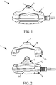
- FIG. 1 illustrates a perspective view of an exemplary embodiment of the neuromodulation electrode assembly 1.
- the embodiment comprises an enclosure having on one side a protrusion 2 extending up to an end having an opening 3.
- An electrical interface 4 is adapted to be coupled to an external apparatus that may provide a signal for the neuromodulation.
- the neuromodulation electrode assembly 1 may further comprises an electro conductive piece 5 that may be coupled to the electrical interface 4 on one end and having the opposite end configured to interact with a patient skin via a portion of the electrode piece 5 that projects outwards through the opening.
- the electrode piece may comprises an electrically conductive solid element 15, 16 coupled on one side to the electrical interface.
- the electrode piece may further comprises an electrically conductive soft deformable element that projects outwards through the opening 3 and which may be adapted to form an interface between the solid element and the patient skin.
- the size of opening 3 may be variable.
- the protrusion 2 may have a shape chosen from: a substantially conical shape, a substantially pyramidal shape, a bell shape, a substantially frustoconical or frustopyramidal, shape, a substantially cylindrical shape, a substantially cuboid shape, a substantially prismatic shape or a substantially polygonal shape.
- the electrically conductive soft deformable element may be made of a material chosen from a gel, a rubber, a polymer or a paraffin with or without an electrically conductive filament.
- the electrically conductive filament 7, 14 may be made of a carbon, a carbide, a graphene, an electrically conductive liquid or electrically conductive solid material such as for instance metal.
- the electrically conductive soft deformable element may be made of a hydrogel being a hydrophilic-material-based gel that may be suspended in a water.
- the hydrophilic-material-based gel may be composed of one or more polymers, potassium carbonate and a cellulose or silicone-based material.
- the electrically conductive soft deformable element may be removable and may be configured to be easily replaceable.
- the electrically conductive soft deformable element may be made by a foil or a flexible film it may be further capable to adapt to the shape of the protrusion 2 and a support portion 12.
- the electrically conductive soft deformable element may be made of a hydrogel.
- the hydrogel may be made via one of an inkjet/extrusion printing, a wet-spinning and/or a physical cross-linking.
- the electrically conductive soft deformable element may be a part or a coating.
- the electrically conductive soft deformable element thickness ranges from 0.05 mm to 55 mm, even more preferably 0.05 mm to 15 mm and even more preferably 0.05 mm to 10 mm.
- the conductive soft deformable element has a contact portion which covers the electrically conductive solid element and has a thickness between 0.005 and 15 mm.
- the electrically conductive soft deformable element has an electrical resistance between 0 ⁇ to 250 k ⁇ .
- the neuromodulation electrode assembly may be electrically coupled via the electrical interface 4 to an external apparatus, which may provide an electrical signal with a desired waveform.
- the waveform frequency may be preferably set between 1 Hz to 20 Hz or even more preferably, set to the frequency between 2 Hz to 6 Hz.
- the pulses may be monophasic or biphasic and, for example, right-angled, sinusoidal or triangular with exponential starts or ends and with widths from 0.1 ms to 5 ms, with amplitude from 0 mA up to 50 mA.
- FIG. 2 illustrates a perspective view of one embodiment that may be utilized with the exemplary neuromodulation electrode assembly.
- the enclosure may comprises a base 6 from which may extend the protrusion 2 that may be removably attached to the base 6.
- the electrically conductive solid element may be rigid with the base and the electrically conductive soft deformable element 7, 14 may be held between the protrusion 2 and the base 6.
- the conductive soft deformable element 7, 14 may be at least partially hollow and the electrically conductive solid element 16, 15 may be received within the conductive soft deformable element.
- the electrically conductive solid element may be at least partially hollow and a portion of the conductive soft deformable element 7 may be received within the electrically conductive solid element.
- the protrusion 2 may be hollow and may cover a support portion 12 belonging to the base 6.
- the support portion 12 may have a shape substantially complementary to the protrusion 2 and protruding from the base up to an apex formed by the electrically conductive solid element, the electrically conductive soft deformable element 7 may be held between the support portion 12 and the protrusion 2.
- the protrusion 2 that may be removably attached to the base 6 may form a removable holder 8 that may be attached to the base 6 by a snap fitting 10 and / or at least one screw or an adhesive layer or a Velcro®-type fastening (hook and loop fastener).
- the electrically conductive soft deformable element 7 When the electrically conductive soft deformable element 7 is held in between the removable protrusion 2 that may form the removable holder 8 and the support portion 12 or the base 6 then the electrically conductive soft deformable element 7 may deform and may consequently form a flexible film capable to adapt to the shape of the electrically conductive solid element 16, 15 and may form an effective electrical interface with the skin and may provide an improved distribution of the neuromodulation signal.
- a variable size opening 3 that may be made in the removable protrusion 2 that may form removable holder 8 it may be possible to control how far the electrically conductive soft deformable element projects outwards through the opening 3.
- this may enable to adapt the interface between the electrically conductive soft deformable element and the patient skin.
- the protrusion 2 that may form a removable holder 8 may be made with the opening 3 having various diameters and/or shapes, consequently enabling a change in the surface area of the electrically conductive soft deformable element 7 that may form an interface between the neuromodulation electrode and the patient's skin, thereby, influencing the neuromodulation current distribution of the neuromodulation electrode to skin electrical interface.
- the electrically conductive soft deformable element may be attached to the base 6 via a feature or a profile made in the base that would secure the electrically conductive soft deformable element in a position relative to the base.
- the electrically conductive soft deformable element may be removeably attached to the base via an adhesive layer.
- the electrically conductive soft deformable element gel electrode may be held within the base as a result of the neuromodulation electrode being put in contact with the skin.
- FIG. 3 illustrates an exploded view that shows one possible embodiment of a configuration of the neuromodulation electrode assembly 1.
- the one possible embodiment of the neuromodulation electrode assembly 1 comprises the enclosure that may comprise the protrusion 2 that may form a removable holder 8 and may be coupled to the support portion 12 belonging to the base 6.
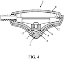
- the embodiment may further comprise a magnetic field source 18, an electrically conductive solid element 15 that may preferably have a shaped end 16 having a surface, an electrically conductive soft deformable element 14 and a means 17 to attach the magnetic field source 18 to the support portion 12 or the base 6.
- the shaped end 16 of the electrically conductive solid element 15 may be one of a semi-circular shape, a conical shape, a pyramidal shape, a bell shape, a substantially frustoconical or frustopyramidal shape, a substantially cylindrical shape, a substantially cuboid shape, a substantially prismatic shape or a substantially polygonal shape.
- the shape end 16 may be coated.
- the magnetic field source 18 may be formed by at least one magnet.
- the magnetic field source 18 may be located inside or outside the enclosure.
- the magnetic field source 18 may be used to increase a depth range of neuromodulation signals transmitted by the neuromodulation electrode assembly 1.
- the magnetic field source 18 may be a permanent magnet or an electromagnet.
- the magnetic field source 18 may have a shape of a hollow cylinder configured to receive a portion of the electrically conductive solid element 15 within.
- the magnetic source 18 may be a group of magnets that may surround a portion of the electrically conductive solid element 15.
- the electrically conductive solid element 15 may be made of various materials, preferably of at least one of diamagnetic materials.
- the shaped end 16 of the element 15 may be formed from at least one of diamagnetic material such as precious metals, a brass, a copper, a carbon, a carbide for example.
- the electrically conductive solid element 15 may be in the form of an electro conductive plate that may have an inner side coupled to the electrical interface 4.
- an electro conductive spring may be coupled to one side of the electrically conductive solid element 15, while the other end of the spring may be connected to the electrical interface 4 forming the electrical connection between the electrically conductive solid element 15 and the electrical interface 4.
- the electro conductive spring may be a coil spring, a compression type spring, a disc spring, a conical spring or a leaf spring.
- the electrically conductive solid element 15 may be positively forced by the spring towards the electrically conductive soft deformable element 14 and that may be consequently forced to project outwards through the opening 3 and may form an outside surface of the shaped end 16 of the electrically conductive solid element 15.
- the magnetic field may be advantageously adjusted using a variable or a tunable excitation of at least one of the electromagnets.
- the variable or tunable excitation may affect the direction of electrical energy flow from the neuromodulation electrode into a patient tissue. This may be advantageously utilized to find a desired nerve, even if the neuromodulation electrode is placed on the skin of a patient inaccurately.
- FIG. 4 illustrates a side cross-sectional view of an exemplary embodiment depicted in the neuromodulation electrode assembly.
- the thickness of the electrically conductive soft deformable element 8, 14 placed between the protrusion 2 that may be formed by a removable holder 8 and the support portion 12 may be controlled via the shape of the protrusion 2 and mating surface of the support portion 12. Additionally or alternatively the thickness of the electrically conductive soft deformable element 14 may be controlled via the shaped end 16 of the electrically conductive solid element 15 and/or via the positive force that may be caused by the spring coupled to the electrically conductive solid element 15.
- the spring may be configured to force the electrically conductive solid element 15 outwards through the opening 3.
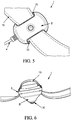
- FIG. 5 illustrates a bottom perspective view of another embodiment featuring an attachment member that may be utilized with the exemplary neuromodulation electrode assembly.
- the enclosure further comprises an attachment member 19 coupled to the base 6.
- the attachment member may be adapted to secure a position of the electrode assembly against the skin in a particular positon.
- the attachment member 19 may be configured to be able to encircle a patient limb 23.
- the attachment member 19 may be made of one of a strap, a belt, a chain or a clip.
- the attachment member 19 may be coupled to the assembly through at least one opening 20 in at least one side of the base 6.
- FIG. 6 illustrates a side perspective view of Figure 5 featuring an attachment member 19 that may be utilized with the exemplary neuromodulation electrode assembly. It shows one possibility, where the attachment member 19 may be secured to the base of the enclosure.
- the attachment member 19 may be made of a rubber, a neoprene, an elastomer, a leather, a plastic or other suitable material.
- the attachment member may be configured to control the depth of the neuromodulation electrode immersion into the limb 23 by controlling the electrode's preload against the limb 23 the attachment member is causing. This may be achieved by tensioning of the attachment member, in other words controlling how tight the attachment member encircles the patient limb 23.
- the electrically conductive soft deformable element may also be configured to contribute, due to its elasticity, to control the depth of the neuromodulation electrode immersion into the limb 23.
- FIG. 7 and FIG. 8 illustrate a perspective view of another embodiment featuring a positioning element 21 that may be utilized with the exemplary neuromodulation electrode assembly.
- the attachment member comprises a positioning element that may be used for an angular positioning of the neuromodulation electrode against the skin of a patient.
- the positioning element 21 may be coupled to the attachment member 19 via one of a strap, a belt, a chain or a clip.
- the positioning element comprises at least one of a cushion, a pad, a pillow or a solid or semi-solid piece.
- the positioning element 21 may be moveably attached to attachment member (21).
- the positioning element may be moveable along the attachment so that it may be moved along and/or around the limb.
- FIG. 9 illustrates a perspective view of another embodiment of the exemplary neuromodulation electrode assembly being attached to a limb 23.
- the embodiment shows an advantageous positioning of neuromodulation electrode where the positioning element 21 may be configured to enable a movement and/or an angular tilt of the neuromodulation electrode to reach and/or secure the most advantageous position of the neuromodulation electrode for the neuromodulation of a particular nerve. This enables to reach a correct location placement of the neuromodulation electrode that is crucial for the effectiveness of the neuromodulation procedure and eliminates a risk of the procedure efficiency reduction due to improper location placement of the neuromodulation electrode.
- the above-mentioned embodiments may offer an effective neuromodulation electrode assembly configured to provide a precise neuromodulation of a desired nerves whilst forming an efficient electro conductive interface between a patient skin and the neuromodulation electrode.
- the electrically conductive soft deformable element may represents a low cost disposable accessory.
Landscapes
- Health & Medical Sciences (AREA)
- Life Sciences & Earth Sciences (AREA)
- Veterinary Medicine (AREA)
- Biomedical Technology (AREA)
- Animal Behavior & Ethology (AREA)
- General Health & Medical Sciences (AREA)
- Public Health (AREA)
- Engineering & Computer Science (AREA)
- Nuclear Medicine, Radiotherapy & Molecular Imaging (AREA)
- Radiology & Medical Imaging (AREA)
- Heart & Thoracic Surgery (AREA)
- Biophysics (AREA)
- Psychology (AREA)
- Physics & Mathematics (AREA)
- Acoustics & Sound (AREA)
- Anesthesiology (AREA)
- Hematology (AREA)
- Electrotherapy Devices (AREA)
- Pain & Pain Management (AREA)
- Child & Adolescent Psychology (AREA)
- Developmental Disabilities (AREA)
- Hospice & Palliative Care (AREA)
- Neurology (AREA)
- Psychiatry (AREA)
- Social Psychology (AREA)
Claims (13)
- Anordnung einer Neuromodulationselektrode (1), welche aufweist:ein Gehäuse, das an einer Seite einen Vorsprung (2) hat, der sich bis zu einem eine Öffnung (3) aufweisenden Ende erstreckt;eine elektrische Schnittstelle (4), die zur Kopplung mit einer externen Vorrichtung ausgelegt ist;ein Strom-leitfähiges Elektrodenstück (5), das an einem Ende mit der elektrischen Schnittstelle gekoppelt ist, und dessen entgegengesetztes Ende konfiguriert ist, und über einen durch die Öffnung auswärts vorstehenden Abschnitt des Elektrodenstücks mit Haut eines Patienten zu interagieren, wobei das Elektrodenstück aufweist:ein elektrisch leitfähiges festes Element (16, 15), das an einer Seite mit der elektrischen Schnittstelle gekoppelt ist; undein elektrisch leitfähiges weiches verformbares Element (7, 14), das durch die Öffnung auswärts vorsteht, und das dazu ausgelegt ist, eine Schnittstelle zwischen dem festen Element und der Haut des Patienten zu bilden,wobei das Gehäuse ferner eine Basis (6) aufweist, von der sich der Vorsprung weg erstreckt, dadurch gekennzeichnet, dassder Vorsprung an der Basis entfernbar angebracht ist, wobei das elektrisch leitfähige feste Element mit der Basis starr ist, wobei der entfernbare Vorsprung hohl ist und einen zu der Basis gehörenden Trägerabschnitt (12) bedeckt, wobei der Trägerabschnitt eine zum Vorsprung im Wesentlichen komplementäre Form hat und von der Basis bis zu einem durch das elektrisch leitfähige feste Element gebildeten Scheitel vorsteht, wobei das elektrisch leitfähige weiche verformbare Element zwischen dem Trägerabschnitt und dem Vorsprung gehalten wird.
- Die Anordnung nach Anspruch 1, wobei der Vorsprung eine Form hat, die ausgewählt ist aus: einer im Wesentlichen konischen Form, einer im Wesentlichen pyramidalen Form, einer Glockenform, einer im Wesentlichen kegelstumpfartigen Form, einer im Wesentlichen zylindrischen Form, einer im Wesentlichen kubischen Form, einer im Wesentlichen prismatischen Form oder einer im Wesentlichen polygonalen Form.
- Die Anordnung nach Anspruch 1 oder 2, wobei das elektrisch leitfähige weiche verformbare Element aus einem Material hergestellt ist, das ausgewählt ist aus einem Gel, einem Gummi, einem Polymer oder einem Paraffin, mit oder ohne elektrisch leitfähiger Faser.
- Die Anordnung nach einem der Ansprüche 1 bis 3, wobei das leitfähige weiche verformbare Element zumindest teilweise hohl ist, und das elektrisch leitfähige feste Element in dem leitfähigen weichen verformbaren Element aufgenommen ist.
- Die Anordnung nach einem der Ansprüche 1 bis 4, wobei das elektrisch leitfähige weiche verformbare Element einen Kontaktabschnitt aufweist, der das elektrisch leitfähige feste Element bedeckt und eine Dicke zwischen 0,005 und 15mm aufweist.
- Die Anordnung nach einem der Ansprüche 1 bis 5, wobei das elektrisch leitfähige weiche verformbare Element einen elektrischen Widerstand zwischen 0Ω und 250Ω aufweist.
- Die Anordnung nach Anspruch 1, wobei der entfernbare Vorsprung an der Basis durch Schnappsitz und/oder zumindest eine Schraube oder eine Haftschicht oder einen Klettverschluss angebracht ist.
- Die Anordnung nach einem der vorhergehenden Ansprüche, wobei die Basis an ein Befestigungselement (19) gekoppelt ist und dazu ausgelegt ist, eine Position der Neuromodulationselektrode gegen die Haut eines Patienten sicherzustellen.
- Die Anordnung nach Anspruch 8, wobei das Befestigungselement konfiguriert ist, in der Lage zu sein, ein Glied (23) eines Patienten zu umschließen.
- Die Anordnung nach einem der Ansprüche 8 bis 9, wobei das Befestigungselement ein Riemen, ein Band, eine Kette oder ein Klipp ist.
- Die Anordnung nach einem der Ansprüche 8 bis 10, wobei das Befestigungselement ein Positionierungselement (21) zur Winkelpositionierung der Neuromodulationselektrode gegen die Haut des Patienten aufweist.
- Die Anordnung nach Anspruch 11, wobei das Positionierungselement ein Polster aufweist.
- Die Anordnung nach Anspruch 12, wobei das Polster entlang dem Befestigungselement beweglich ist.
Priority Applications (1)
| Application Number | Priority Date | Filing Date | Title |
|---|---|---|---|
| EP20166069.3A EP3714935B1 (de) | 2017-10-11 | 2018-10-11 | Neuromodulationselektrodenanordnung |
Applications Claiming Priority (2)
| Application Number | Priority Date | Filing Date | Title |
|---|---|---|---|
| CZ2017647 | 2017-10-11 | ||
| PCT/EP2018/077798 WO2019073003A1 (en) | 2017-10-11 | 2018-10-11 | NEUROMODULATION ELECTRODE ASSEMBLY |
Related Child Applications (2)
| Application Number | Title | Priority Date | Filing Date |
|---|---|---|---|
| EP20166069.3A Division-Into EP3714935B1 (de) | 2017-10-11 | 2018-10-11 | Neuromodulationselektrodenanordnung |
| EP20166069.3A Division EP3714935B1 (de) | 2017-10-11 | 2018-10-11 | Neuromodulationselektrodenanordnung |
Publications (2)
| Publication Number | Publication Date |
|---|---|
| EP3493874A1 EP3493874A1 (de) | 2019-06-12 |
| EP3493874B1 true EP3493874B1 (de) | 2020-08-12 |
Family
ID=66379677
Family Applications (2)
| Application Number | Title | Priority Date | Filing Date |
|---|---|---|---|
| EP18786299.0A Active EP3493874B1 (de) | 2017-10-11 | 2018-10-11 | Neuromodulierende elektrodenanordnung |
| EP20166069.3A Active EP3714935B1 (de) | 2017-10-11 | 2018-10-11 | Neuromodulationselektrodenanordnung |
Family Applications After (1)
| Application Number | Title | Priority Date | Filing Date |
|---|---|---|---|
| EP20166069.3A Active EP3714935B1 (de) | 2017-10-11 | 2018-10-11 | Neuromodulationselektrodenanordnung |
Country Status (10)
| Country | Link |
|---|---|
| US (1) | US11400277B2 (de) |
| EP (2) | EP3493874B1 (de) |
| JP (2) | JP7036465B2 (de) |
| KR (2) | KR102651846B1 (de) |
| CN (1) | CN111212676B (de) |
| AU (1) | AU2018348807B2 (de) |
| DK (1) | DK3493874T3 (de) |
| ES (2) | ES2970834T3 (de) |
| RU (1) | RU2746456C1 (de) |
| WO (1) | WO2019073003A1 (de) |
Families Citing this family (20)
| Publication number | Priority date | Publication date | Assignee | Title |
|---|---|---|---|---|
| EP3498332B1 (de) | 2013-01-21 | 2021-07-14 | Cala Health, Inc. | Vorrichtungen zur tremor-steuerung |
| US12453853B2 (en) | 2013-01-21 | 2025-10-28 | Cala Health, Inc. | Multi-modal stimulation for treating tremor |
| AU2015271774B2 (en) | 2014-06-02 | 2020-04-16 | Cala Health, Inc. | Systems and methods for peripheral nerve stimulation to treat tremor |
| CN119565022A (zh) | 2015-06-10 | 2025-03-07 | 卡拉健康公司 | 用于外周神经刺激以利用可拆卸治疗和监测单元治疗震颤的系统和方法 |
| WO2017023864A1 (en) | 2015-07-31 | 2017-02-09 | Cala Health, Inc. | Systems, devices, and method for the treatment of osteoarthritis |
| EP3352843B1 (de) | 2015-09-23 | 2021-06-23 | Cala Health, Inc. | Gerät zur peripheren nervenstimulation im finger zur behandlung von hand-tremores |
| WO2017132067A2 (en) | 2016-01-21 | 2017-08-03 | Cala Health, Inc. | Systems, methods and devices for peripheral neuromodulation for treating diseases related to overactive bladder |
| CN109803717B (zh) | 2016-08-25 | 2024-01-09 | 卡拉健康公司 | 通过周围神经刺激治疗心脏机能障碍的系统和方法 |
| EP3606604A4 (de) | 2017-04-03 | 2020-12-16 | Cala Health, Inc. | Systeme, verfahren und vorrichtungen zur peripheren neuromodulation zur behandlung von erkrankungen im zusammenhang mit überaktiver blase |
| RU2746456C1 (ru) * | 2017-10-11 | 2021-04-14 | Тесла Медикал С.Р.О. | Электрод для нейромодуляции в сборе |
| US11857778B2 (en) | 2018-01-17 | 2024-01-02 | Cala Health, Inc. | Systems and methods for treating inflammatory bowel disease through peripheral nerve stimulation |
| US12251560B1 (en) | 2019-08-13 | 2025-03-18 | Cala Health, Inc. | Connection quality determination for wearable neurostimulation systems |
| US11996645B2 (en) | 2019-10-01 | 2024-05-28 | Verily Life Sciences Llc | Separable high density connectors for implantable device |
| US11890468B1 (en) | 2019-10-03 | 2024-02-06 | Cala Health, Inc. | Neurostimulation systems with event pattern detection and classification |
| WO2023038539A1 (ru) * | 2021-09-07 | 2023-03-16 | Общество с ограниченной ответственностью "Косима" (ООО "Косима") | Неинвазивная электроидная матрица спинального нейропротеза и способ ее применения |
| JP2023153464A (ja) * | 2022-04-05 | 2023-10-18 | 株式会社アイリカ | 美顔器 |
| JP7834569B2 (ja) * | 2022-05-02 | 2026-03-24 | 株式会社三共 | 遊技機 |
| JP7834567B2 (ja) * | 2022-05-02 | 2026-03-24 | 株式会社三共 | 遊技機 |
| JP7834568B2 (ja) * | 2022-05-02 | 2026-03-24 | 株式会社三共 | 遊技機 |
| JP7834566B2 (ja) * | 2022-05-02 | 2026-03-24 | 株式会社三共 | 遊技機 |
Family Cites Families (21)
| Publication number | Priority date | Publication date | Assignee | Title |
|---|---|---|---|---|
| NL7402355A (nl) * | 1974-02-21 | 1975-08-25 | Philips Nv | Huidelektrode. |
| US5358513A (en) | 1992-12-09 | 1994-10-25 | Medtronic, Inc. | Parameter selection and electrode placement of neuromuscular electrical stimulation apparatus |
| US7047078B2 (en) * | 2001-03-30 | 2006-05-16 | Case Western Reserve University | Methods for stimulating components in, on, or near the pudendal nerve or its branches to achieve selective physiologic responses |
| US6735480B2 (en) * | 2001-06-29 | 2004-05-11 | Abbott Laboratories | Electro-acupuncture device with D-shaped stimulation electrodes |
| GB0230361D0 (en) * | 2002-12-27 | 2003-02-05 | Koninkl Philips Electronics Nv | Electrode arrangement |
| US8417352B2 (en) * | 2004-10-19 | 2013-04-09 | Meagan Medical, Inc. | System and method for stimulating sensory nerves |
| US8874227B2 (en) * | 2009-03-20 | 2014-10-28 | ElectroCore, LLC | Devices and methods for non-invasive capacitive electrical stimulation and their use for vagus nerve stimulation on the neck of a patient |
| GB0523916D0 (en) * | 2005-11-24 | 2006-01-04 | Femeda Ltd | Compressible electrodes |
| US8170683B2 (en) | 2007-12-14 | 2012-05-01 | Ethicon, Inc. | Dermatome stimulation devices and methods |
| US8660656B2 (en) | 2009-10-16 | 2014-02-25 | Hanger, Inc. | Cuff assembly |
| US8938303B1 (en) * | 2010-06-01 | 2015-01-20 | Brandie Matsen | Restless leg therapeutic device |
| US10016233B2 (en) * | 2010-12-06 | 2018-07-10 | Biosense Webster (Israel) Ltd. | Treatment of atrial fibrillation using high-frequency pacing and ablation of renal nerves |
| EP2928550B1 (de) * | 2012-12-07 | 2023-06-07 | Medtronic, Inc. | Minimal-invasives implantierbares neurostimulationssystem |
| US9254382B2 (en) * | 2013-02-08 | 2016-02-09 | ReliefBand Technologies LLC | Apparatus for transcutaneous electrical stimulation of the tibial nerve |
| WO2015065442A1 (en) * | 2013-10-31 | 2015-05-07 | Advanced Bionics Ag | Headpieces and implantable cochlear stimulation systems including the same |
| CN107106841B (zh) * | 2014-10-31 | 2021-06-25 | 阿文特公司 | 经由胫后神经刺激来监测和治疗病症的方法和系统 |
| CZ306538B6 (cs) | 2015-07-06 | 2017-03-01 | Tesla Medical, S.R.O. | Elektrostimulační zařízení |
| CZ306539B6 (cs) | 2015-07-06 | 2017-03-01 | Tesla Medical, S.R.O. | Elektrostimulační zařízení |
| CN109069828A (zh) * | 2015-12-15 | 2018-12-21 | 波士顿科学医学有限公司 | 用于头痛的非侵入性治疗的系统和方法 |
| WO2017132067A2 (en) * | 2016-01-21 | 2017-08-03 | Cala Health, Inc. | Systems, methods and devices for peripheral neuromodulation for treating diseases related to overactive bladder |
| RU2746456C1 (ru) * | 2017-10-11 | 2021-04-14 | Тесла Медикал С.Р.О. | Электрод для нейромодуляции в сборе |
-
2018
- 2018-10-11 RU RU2020113390A patent/RU2746456C1/ru active
- 2018-10-11 EP EP18786299.0A patent/EP3493874B1/de active Active
- 2018-10-11 CN CN201880066581.5A patent/CN111212676B/zh active Active
- 2018-10-11 WO PCT/EP2018/077798 patent/WO2019073003A1/en not_active Ceased
- 2018-10-11 KR KR1020207011054A patent/KR102651846B1/ko active Active
- 2018-10-11 US US16/755,651 patent/US11400277B2/en active Active
- 2018-10-11 AU AU2018348807A patent/AU2018348807B2/en active Active
- 2018-10-11 JP JP2020520454A patent/JP7036465B2/ja active Active
- 2018-10-11 ES ES20166069T patent/ES2970834T3/es active Active
- 2018-10-11 DK DK18786299.0T patent/DK3493874T3/da active
- 2018-10-11 EP EP20166069.3A patent/EP3714935B1/de active Active
- 2018-10-11 KR KR1020247009550A patent/KR102720932B1/ko active Active
- 2018-10-11 ES ES18786299T patent/ES2821129T3/es active Active
-
2022
- 2022-02-22 JP JP2022025698A patent/JP7450280B2/ja active Active
Non-Patent Citations (1)
| Title |
|---|
| None * |
Also Published As
| Publication number | Publication date |
|---|---|
| WO2019073003A1 (en) | 2019-04-18 |
| ES2821129T3 (es) | 2021-04-23 |
| AU2018348807A1 (en) | 2020-04-23 |
| KR20200069306A (ko) | 2020-06-16 |
| EP3714935B1 (de) | 2024-01-31 |
| RU2021109742A (ru) | 2021-05-17 |
| US11400277B2 (en) | 2022-08-02 |
| CA3077601A1 (en) | 2019-04-18 |
| KR20240042239A (ko) | 2024-04-01 |
| RU2021109742A3 (de) | 2021-10-13 |
| KR102720932B1 (ko) | 2024-10-24 |
| EP3714935A1 (de) | 2020-09-30 |
| JP7036465B2 (ja) | 2022-03-15 |
| JP2022075684A (ja) | 2022-05-18 |
| EP3714935C0 (de) | 2024-01-31 |
| US20200282201A1 (en) | 2020-09-10 |
| ES2970834T3 (es) | 2024-05-30 |
| AU2018348807B2 (en) | 2024-01-04 |
| KR102651846B1 (ko) | 2024-03-27 |
| CN111212676A (zh) | 2020-05-29 |
| EP3493874A1 (de) | 2019-06-12 |
| CN111212676B (zh) | 2023-08-15 |
| DK3493874T3 (da) | 2020-10-12 |
| JP2020536664A (ja) | 2020-12-17 |
| BR112020006520A2 (pt) | 2020-10-13 |
| RU2746456C1 (ru) | 2021-04-14 |
| JP7450280B2 (ja) | 2024-03-15 |
Similar Documents
| Publication | Publication Date | Title |
|---|---|---|
| EP3493874B1 (de) | Neuromodulierende elektrodenanordnung | |
| US9956405B2 (en) | Transdermal electrical stimulation at the neck to induce neuromodulation | |
| US10646708B2 (en) | Transdermal electrical stimulation at the neck | |
| JP7077297B2 (ja) | 厳密にn個の電極および改善された乾式電極を用いてn個の神経を刺激するためのシステムおよび方法 | |
| EP2588187B1 (de) | Einmal-elektrode für die elektrostimulation | |
| EP3458150A1 (de) | Transdermale elektrischer stimulation am hals zur induktion von neuromodulation | |
| US20090048642A1 (en) | Neurostimulation | |
| IL259474B (en) | Device for subcutaneous injection for the treatment of premature ejaculation or erectile dysfunction and the methods of its use | |
| CN102939066A (zh) | 电极装置 | |
| US20190282801A1 (en) | Systems and methods for the treatment of head pain | |
| US20220118245A1 (en) | System for electrical stimulation of nerves | |
| CA3077601C (en) | Neuromodulation electrode assembly | |
| RU2771731C2 (ru) | Электрод для нейромодуляции в сборе | |
| US10874869B2 (en) | Electrostimulation device | |
| BR112020006520B1 (pt) | Montagem de eletrodos de neuromodulação | |
| RU40896U1 (ru) | Электродное устройство | |
| CZ306539B6 (cs) | Elektrostimulační zařízení |
Legal Events
| Date | Code | Title | Description |
|---|---|---|---|
| STAA | Information on the status of an ep patent application or granted ep patent |
Free format text: STATUS: UNKNOWN |
|
| STAA | Information on the status of an ep patent application or granted ep patent |
Free format text: STATUS: THE INTERNATIONAL PUBLICATION HAS BEEN MADE |
|
| PUAI | Public reference made under article 153(3) epc to a published international application that has entered the european phase |
Free format text: ORIGINAL CODE: 0009012 |
|
| STAA | Information on the status of an ep patent application or granted ep patent |
Free format text: STATUS: REQUEST FOR EXAMINATION WAS MADE |
|
| 17P | Request for examination filed |
Effective date: 20190215 |
|
| AK | Designated contracting states |
Kind code of ref document: A1 Designated state(s): AL AT BE BG CH CY CZ DE DK EE ES FI FR GB GR HR HU IE IS IT LI LT LU LV MC MK MT NL NO PL PT RO RS SE SI SK SM TR |
|
| AX | Request for extension of the european patent |
Extension state: BA ME |
|
| GRAP | Despatch of communication of intention to grant a patent |
Free format text: ORIGINAL CODE: EPIDOSNIGR1 |
|
| STAA | Information on the status of an ep patent application or granted ep patent |
Free format text: STATUS: GRANT OF PATENT IS INTENDED |
|
| DAV | Request for validation of the european patent (deleted) | ||
| DAX | Request for extension of the european patent (deleted) | ||
| INTG | Intention to grant announced |
Effective date: 20191125 |
|
| GRAJ | Information related to disapproval of communication of intention to grant by the applicant or resumption of examination proceedings by the epo deleted |
Free format text: ORIGINAL CODE: EPIDOSDIGR1 |
|
| STAA | Information on the status of an ep patent application or granted ep patent |
Free format text: STATUS: REQUEST FOR EXAMINATION WAS MADE |
|
| INTC | Intention to grant announced (deleted) | ||
| GRAP | Despatch of communication of intention to grant a patent |
Free format text: ORIGINAL CODE: EPIDOSNIGR1 |
|
| STAA | Information on the status of an ep patent application or granted ep patent |
Free format text: STATUS: GRANT OF PATENT IS INTENDED |
|
| INTG | Intention to grant announced |
Effective date: 20200513 |
|
| GRAS | Grant fee paid |
Free format text: ORIGINAL CODE: EPIDOSNIGR3 |
|
| GRAA | (expected) grant |
Free format text: ORIGINAL CODE: 0009210 |
|
| STAA | Information on the status of an ep patent application or granted ep patent |
Free format text: STATUS: THE PATENT HAS BEEN GRANTED |
|
| AK | Designated contracting states |
Kind code of ref document: B1 Designated state(s): AL AT BE BG CH CY CZ DE DK EE ES FI FR GB GR HR HU IE IS IT LI LT LU LV MC MK MT NL NO PL PT RO RS SE SI SK SM TR |
|
| REG | Reference to a national code |
Ref country code: CH Ref legal event code: EP |
|
| REG | Reference to a national code |
Ref country code: IE Ref legal event code: FG4D |
|
| REG | Reference to a national code |
Ref country code: DE Ref legal event code: R096 Ref document number: 602018006918 Country of ref document: DE |
|
| REG | Reference to a national code |
Ref country code: AT Ref legal event code: REF Ref document number: 1300927 Country of ref document: AT Kind code of ref document: T Effective date: 20200915 Ref country code: CH Ref legal event code: NV Representative=s name: VALIPAT S.A. C/O BOVARD SA NEUCHATEL, CH |
|
| REG | Reference to a national code |
Ref country code: FI Ref legal event code: FGE |
|
| REG | Reference to a national code |
Ref country code: DK Ref legal event code: T3 Effective date: 20201007 |
|
| REG | Reference to a national code |
Ref country code: SE Ref legal event code: TRGR |
|
| REG | Reference to a national code |
Ref country code: NL Ref legal event code: FP |
|
| REG | Reference to a national code |
Ref country code: NO Ref legal event code: T2 Effective date: 20200812 |
|
| REG | Reference to a national code |
Ref country code: LT Ref legal event code: MG4D |
|
| PG25 | Lapsed in a contracting state [announced via postgrant information from national office to epo] |
Ref country code: HR Free format text: LAPSE BECAUSE OF FAILURE TO SUBMIT A TRANSLATION OF THE DESCRIPTION OR TO PAY THE FEE WITHIN THE PRESCRIBED TIME-LIMIT Effective date: 20200812 Ref country code: LT Free format text: LAPSE BECAUSE OF FAILURE TO SUBMIT A TRANSLATION OF THE DESCRIPTION OR TO PAY THE FEE WITHIN THE PRESCRIBED TIME-LIMIT Effective date: 20200812 Ref country code: GR Free format text: LAPSE BECAUSE OF FAILURE TO SUBMIT A TRANSLATION OF THE DESCRIPTION OR TO PAY THE FEE WITHIN THE PRESCRIBED TIME-LIMIT Effective date: 20201113 |
|
| REG | Reference to a national code |
Ref country code: AT Ref legal event code: MK05 Ref document number: 1300927 Country of ref document: AT Kind code of ref document: T Effective date: 20200812 |
|
| PG25 | Lapsed in a contracting state [announced via postgrant information from national office to epo] |
Ref country code: LV Free format text: LAPSE BECAUSE OF FAILURE TO SUBMIT A TRANSLATION OF THE DESCRIPTION OR TO PAY THE FEE WITHIN THE PRESCRIBED TIME-LIMIT Effective date: 20200812 Ref country code: RS Free format text: LAPSE BECAUSE OF FAILURE TO SUBMIT A TRANSLATION OF THE DESCRIPTION OR TO PAY THE FEE WITHIN THE PRESCRIBED TIME-LIMIT Effective date: 20200812 Ref country code: IS Free format text: LAPSE BECAUSE OF FAILURE TO SUBMIT A TRANSLATION OF THE DESCRIPTION OR TO PAY THE FEE WITHIN THE PRESCRIBED TIME-LIMIT Effective date: 20201212 |
|
| REG | Reference to a national code |
Ref country code: ES Ref legal event code: FG2A Ref document number: 2821129 Country of ref document: ES Kind code of ref document: T3 Effective date: 20210423 |
|
| PG25 | Lapsed in a contracting state [announced via postgrant information from national office to epo] |
Ref country code: SM Free format text: LAPSE BECAUSE OF FAILURE TO SUBMIT A TRANSLATION OF THE DESCRIPTION OR TO PAY THE FEE WITHIN THE PRESCRIBED TIME-LIMIT Effective date: 20200812 Ref country code: RO Free format text: LAPSE BECAUSE OF FAILURE TO SUBMIT A TRANSLATION OF THE DESCRIPTION OR TO PAY THE FEE WITHIN THE PRESCRIBED TIME-LIMIT Effective date: 20200812 Ref country code: EE Free format text: LAPSE BECAUSE OF FAILURE TO SUBMIT A TRANSLATION OF THE DESCRIPTION OR TO PAY THE FEE WITHIN THE PRESCRIBED TIME-LIMIT Effective date: 20200812 |
|
| REG | Reference to a national code |
Ref country code: DE Ref legal event code: R097 Ref document number: 602018006918 Country of ref document: DE |
|
| PG25 | Lapsed in a contracting state [announced via postgrant information from national office to epo] |
Ref country code: AL Free format text: LAPSE BECAUSE OF FAILURE TO SUBMIT A TRANSLATION OF THE DESCRIPTION OR TO PAY THE FEE WITHIN THE PRESCRIBED TIME-LIMIT Effective date: 20200812 Ref country code: AT Free format text: LAPSE BECAUSE OF FAILURE TO SUBMIT A TRANSLATION OF THE DESCRIPTION OR TO PAY THE FEE WITHIN THE PRESCRIBED TIME-LIMIT Effective date: 20200812 |
|
| PLBE | No opposition filed within time limit |
Free format text: ORIGINAL CODE: 0009261 |
|
| STAA | Information on the status of an ep patent application or granted ep patent |
Free format text: STATUS: NO OPPOSITION FILED WITHIN TIME LIMIT |
|
| PG25 | Lapsed in a contracting state [announced via postgrant information from national office to epo] |
Ref country code: MC Free format text: LAPSE BECAUSE OF FAILURE TO SUBMIT A TRANSLATION OF THE DESCRIPTION OR TO PAY THE FEE WITHIN THE PRESCRIBED TIME-LIMIT Effective date: 20200812 Ref country code: LU Free format text: LAPSE BECAUSE OF NON-PAYMENT OF DUE FEES Effective date: 20201011 Ref country code: SK Free format text: LAPSE BECAUSE OF FAILURE TO SUBMIT A TRANSLATION OF THE DESCRIPTION OR TO PAY THE FEE WITHIN THE PRESCRIBED TIME-LIMIT Effective date: 20200812 |
|
| 26N | No opposition filed |
Effective date: 20210514 |
|
| PG25 | Lapsed in a contracting state [announced via postgrant information from national office to epo] |
Ref country code: SI Free format text: LAPSE BECAUSE OF FAILURE TO SUBMIT A TRANSLATION OF THE DESCRIPTION OR TO PAY THE FEE WITHIN THE PRESCRIBED TIME-LIMIT Effective date: 20200812 |
|
| PG25 | Lapsed in a contracting state [announced via postgrant information from national office to epo] |
Ref country code: MT Free format text: LAPSE BECAUSE OF FAILURE TO SUBMIT A TRANSLATION OF THE DESCRIPTION OR TO PAY THE FEE WITHIN THE PRESCRIBED TIME-LIMIT Effective date: 20200812 Ref country code: CY Free format text: LAPSE BECAUSE OF FAILURE TO SUBMIT A TRANSLATION OF THE DESCRIPTION OR TO PAY THE FEE WITHIN THE PRESCRIBED TIME-LIMIT Effective date: 20200812 |
|
| PG25 | Lapsed in a contracting state [announced via postgrant information from national office to epo] |
Ref country code: MK Free format text: LAPSE BECAUSE OF FAILURE TO SUBMIT A TRANSLATION OF THE DESCRIPTION OR TO PAY THE FEE WITHIN THE PRESCRIBED TIME-LIMIT Effective date: 20200812 |
|
| PG25 | Lapsed in a contracting state [announced via postgrant information from national office to epo] |
Ref country code: PT Free format text: LAPSE BECAUSE OF FAILURE TO SUBMIT A TRANSLATION OF THE DESCRIPTION OR TO PAY THE FEE WITHIN THE PRESCRIBED TIME-LIMIT Effective date: 20200812 |
|
| P01 | Opt-out of the competence of the unified patent court (upc) registered |
Effective date: 20230526 |
|
| PGFP | Annual fee paid to national office [announced via postgrant information from national office to epo] |
Ref country code: FI Payment date: 20250922 Year of fee payment: 8 |
|
| PGFP | Annual fee paid to national office [announced via postgrant information from national office to epo] |
Ref country code: DK Payment date: 20250930 Year of fee payment: 8 |
|
| PGFP | Annual fee paid to national office [announced via postgrant information from national office to epo] |
Ref country code: NL Payment date: 20250926 Year of fee payment: 8 Ref country code: PL Payment date: 20250922 Year of fee payment: 8 |
|
| PGFP | Annual fee paid to national office [announced via postgrant information from national office to epo] |
Ref country code: BG Payment date: 20250924 Year of fee payment: 8 |
|
| PGFP | Annual fee paid to national office [announced via postgrant information from national office to epo] |
Ref country code: FR Payment date: 20250916 Year of fee payment: 8 |
|
| PGFP | Annual fee paid to national office [announced via postgrant information from national office to epo] |
Ref country code: IE Payment date: 20250918 Year of fee payment: 8 |
|
| REG | Reference to a national code |
Ref country code: CH Ref legal event code: U11 Free format text: ST27 STATUS EVENT CODE: U-0-0-U10-U11 (AS PROVIDED BY THE NATIONAL OFFICE) Effective date: 20251101 |
|
| PGFP | Annual fee paid to national office [announced via postgrant information from national office to epo] |
Ref country code: DE Payment date: 20251015 Year of fee payment: 8 |
|
| PGFP | Annual fee paid to national office [announced via postgrant information from national office to epo] |
Ref country code: GB Payment date: 20251023 Year of fee payment: 8 |
|
| PGFP | Annual fee paid to national office [announced via postgrant information from national office to epo] |
Ref country code: NO Payment date: 20250930 Year of fee payment: 8 |
|
| PGFP | Annual fee paid to national office [announced via postgrant information from national office to epo] |
Ref country code: IT Payment date: 20251007 Year of fee payment: 8 |
|
| PGFP | Annual fee paid to national office [announced via postgrant information from national office to epo] |
Ref country code: TR Payment date: 20251002 Year of fee payment: 8 Ref country code: BE Payment date: 20251020 Year of fee payment: 8 |
|
| PGFP | Annual fee paid to national office [announced via postgrant information from national office to epo] |
Ref country code: CH Payment date: 20251101 Year of fee payment: 8 Ref country code: SE Payment date: 20251029 Year of fee payment: 8 |
|
| PGFP | Annual fee paid to national office [announced via postgrant information from national office to epo] |
Ref country code: CZ Payment date: 20251009 Year of fee payment: 8 |
|
| PGFP | Annual fee paid to national office [announced via postgrant information from national office to epo] |
Ref country code: ES Payment date: 20251110 Year of fee payment: 8 |