EP3492306B1 - Automatische stopp-steuerungsvorrichtung für einen zug - Google Patents
Automatische stopp-steuerungsvorrichtung für einen zug Download PDFInfo
- Publication number
- EP3492306B1 EP3492306B1 EP17833937.0A EP17833937A EP3492306B1 EP 3492306 B1 EP3492306 B1 EP 3492306B1 EP 17833937 A EP17833937 A EP 17833937A EP 3492306 B1 EP3492306 B1 EP 3492306B1
- Authority
- EP
- European Patent Office
- Prior art keywords
- train
- calculation means
- relative distance
- speed
- control device
- Prior art date
- Legal status (The legal status is an assumption and is not a legal conclusion. Google has not performed a legal analysis and makes no representation as to the accuracy of the status listed.)
- Active
Links
Images


Classifications
-
- B—PERFORMING OPERATIONS; TRANSPORTING
- B61—RAILWAYS
- B61L—GUIDING RAILWAY TRAFFIC; ENSURING THE SAFETY OF RAILWAY TRAFFIC
- B61L25/00—Recording or indicating positions or identities of vehicles or trains or setting of track apparatus
- B61L25/02—Indicating or recording positions or identities of vehicles or trains
- B61L25/026—Relative localisation, e.g. using odometer
-
- B—PERFORMING OPERATIONS; TRANSPORTING
- B60—VEHICLES IN GENERAL
- B60L—PROPULSION OF ELECTRICALLY-PROPELLED VEHICLES; SUPPLYING ELECTRIC POWER FOR AUXILIARY EQUIPMENT OF ELECTRICALLY-PROPELLED VEHICLES; ELECTRODYNAMIC BRAKE SYSTEMS FOR VEHICLES IN GENERAL; MAGNETIC SUSPENSION OR LEVITATION FOR VEHICLES; MONITORING OPERATING VARIABLES OF ELECTRICALLY-PROPELLED VEHICLES; ELECTRIC SAFETY DEVICES FOR ELECTRICALLY-PROPELLED VEHICLES
- B60L15/00—Methods, circuits, or devices for controlling the traction-motor speed of electrically-propelled vehicles
- B60L15/40—Adaptation of control equipment on vehicle for remote actuation from a stationary place
-
- B—PERFORMING OPERATIONS; TRANSPORTING
- B61—RAILWAYS
- B61L—GUIDING RAILWAY TRAFFIC; ENSURING THE SAFETY OF RAILWAY TRAFFIC
- B61L15/00—Indicators provided on the vehicle or train for signalling purposes
- B61L15/0062—On-board target speed calculation or supervision
-
- B—PERFORMING OPERATIONS; TRANSPORTING
- B61—RAILWAYS
- B61L—GUIDING RAILWAY TRAFFIC; ENSURING THE SAFETY OF RAILWAY TRAFFIC
- B61L23/00—Control, warning or like safety means along the route or between vehicles or trains
- B61L23/04—Control, warning or like safety means along the route or between vehicles or trains for monitoring the mechanical state of the route
- B61L23/041—Obstacle detection
Definitions
- the present invention relates to a train automatic stop control device configured to calculate a current position of a train from a relative distance between the train and an object installed on the ground and control the traveling of the train.
- ATOs Automatic Train Control
- TSC Train automatic stop control
- Nonpatent Literature 1 that is related art discloses a configuration of a general train automatic stop control device.
- the train automatic stop control device uses a device, which is installed on a vehicle and is called an on-vehicle coil, to receive positional information from a ground coil installed on the ground (in a railroad track) and configured to transmit the positional information of the ground coil. Then, the train automatic stop control device determines a current position of a target train based on the received positional information. Multiple ground coils are installed near a target stop position. The train automatic stop control device corrects the current position of the train every time the on-vehicle coil passes through a ground coil.
- the train automatic stop control device compares the speed of the train with a speed set for the current position and indicated in a TASC pattern (data indicated by combinations of positions and speeds) held in the train automatic stop control device in advance.
- the train automatic stop control device stops the train at the target stop position by controlling a brake so that the speeds match each other.
- ground coils need to be installed as devices within a railroad track.
- the cost of installing a railroad device largely varies depending on whether the railroad device is to be installed in or outside a railroad track.
- advanced safety measures are necessary to avoid contact with a train, and the cost of installing the device is higher, compared with the case where the device is installed outside the railroad track or installed on or above a platform.
- a train automatic stop control device is installed using the technique described in Nonpatent Literature 1, there is a problem that the installation is costly.
- ground coils are discretely installed and the current position cannot be continuously corrected.
- the present invention has been made in consideration of the aforementioned problems, and a train automatic stop control device configured to determine a current position of a train using a device installed outside a railroad track is proposed. According to the present invention, since a device does not need to be installed in a railroad track and an on-vehicle coil is not required, the train automatic stop control device can be introduced with low cost. In addition, although the current position is discretely corrected using ground coils in a conventional technique, the current position is continuously corrected and the accuracy of the current position is improved.
- the present invention it is possible to stop the train at a target stop position using the device installed outside a railroad track.
- the accuracy of the current position is improved.
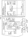
- Fig. 1 is a diagram related to a train automatic stop control device (TASC device) included in a general automatic train operation (ATO) .
- Figs. 2 to 5 are diagrams describing train automatic stop control devices according to the embodiments of the present invention.
- units shown in Figs. 1 to 5 are devices, each of which is composed of any of a processor, a storage medium, and a program, or a combination thereof.
- the processor reads the program stored in the storage medium and enables various functions.
- Fig. 1 is a diagram showing a configuration of the general train automatic stop control device.
- the train automatic stop control device uses speed/position calculation means to detect a speed signal from a tacho-generator installed on a wheel shaft and detects positional information from an on-vehicle coil for communicating with a ground coil.
- the train automatic stop control device uses control command calculation means to calculate a braking command based on the acquired speed signal and the positional information and outputs the calculated braking command to a vehicle information control device and a braking and driving control device.
- the train automatic stop control device includes the speed/position calculation means configured to calculate a speed signal and positional information and the control command calculation means configured to calculate a braking command.
- the control command calculation means includes a planning unit having a planning function and tracing means having a tracing function.
- the speed/position calculation means calculates a current position from positional information of a departure station and an integrated value of a vehicle speed. However, since an integration error is included in the integrated value of the vehicle speed, the speed/position calculation means corrects the current position to information received from a ground coil upon receiving the positional information from the ground coil. When the current position is between ground coils, the speed/position calculation means calculates the current position using the integrated value of the vehicle speed.
- the planning function is a function of calculating a target speed by crosschecking a braking speed before arrival at a station stop position held in advance with a current vehicle position.
- the tracing function is a function of receiving a speed deviation between the target speed and a current vehicle speed and calculating braking force to be output.
- the train automatic stop control device causes the calculated braking force to be included in a braking command and outputs the braking command including the calculated braking force to the vehicle information control device and the braking and driving control device.
- the vehicle information control device is a device configured to manage information transfer in a vehicle.
- the vehicle information control device receives the braking command from the train automatic stop control device, the vehicle information control device outputs the received braking command to the braking and driving control device.
- the braking and driving control device controls the traveling of a train based on the received braking command.
- a first embodiment describes a train automatic stop control device configured to calculate a current position of a target train based on a relative distance between the target train and an object installed in a railroad station and serving as a reference for position correction.
- Fig. 2 is a diagram showing a functional configuration of the train automatic stop control device 201 according to the first embodiment.
- the train automatic stop control device 201 includes speed/position calculation means 202, relative distance calculation means 203, an object position database 204, and control command calculation means 205.
- the train automatic stop control device 201 calculates a braking command and outputs the calculated braking command to a braking and driving control device via a vehicle information control device.
- the speed/position calculation means 202 acquires a speed signal indicating a rotational speed of a wheel shaft from a tacho-generator 206 installed on the wheel shaft and calculates the current position of the train from the acquired speed signal, a circumferential length of a wheel, and positional information of a station from which the train is departed.
- the speed/position calculation means 202 acquires the relative distance from the relative distance calculation means 203, acquires the position of the object from the object position database 204, and calculates the current position of the target train from the position of the object and the relative distance.
- the current position of the target train is hereinafter merely referred to as "current position" in some cases.
- the relative distance calculation means 203 calculates a relative distance between the target train and an object 207 installed outside a railroad track (or installed on or above a platform, for example) and serving as a reference for position correction. It is sufficient if at least one object 207 is installed near a single target stop position. It is, however, desirable that multiple objects 207 be installed on or above a platform in consideration of the fact that an object 207 may not be recognized.
- the relative distance calculation means 203 may calculate the relative distance by causing an imaging device such as a camera to recognize an image of the object or by using radio wave irradiation with a millimeter-wave or the like or laser irradiation.
- a distance between the target train and the object 207 installed outside the railroad track is calculated, and a method for calculating the distance is not limited.
- the relative distance calculation means 203 switches the object to an object to be recognized next.
- the control command calculation means 205 receives information of the speed and current position of the target train from the speed/position calculation means 202 and calculates a braking command from a speed deviation between the speed of the target train and a speed set for the current position and indicated in a TASC pattern.
- Fig. 3 is a diagram showing a procedure (flowchart) for a process of speed and position calculation to be executed by the speed/position calculation means 202.
- the flowchart shown in Fig. 3 is executed for each calculation time interval of the train automatic stop control device 201.
- a subject that executes processes of the following steps is the speed/position calculation means 202 and is omitted in descriptions of the following steps.
- a speed signal is acquired from the tacho-generator 206. After that, the process proceeds to step 302.
- a vehicle speed is calculated based on data indicating the acquired speed signal, the circumferential length of the wheel, and the like. After that, the process proceeds to step 303.
- the current position at a previous calculation time interval is acquired. After that, the process proceeds to step 304.
- the current position of the target train is calculated according to the following equation. After that, process proceeds to step 305.
- the relative distance is acquired from the relative distance calculation means 203. After that, the process proceeds to step 307.
- the position of the object is acquired. Specifically, an object's position that is closest to the current position calculated in step 304 in the traveling direction is searched from the object position database 204 and acquired. After that, the process proceeds to step 308.
- the object may be installed and dedicated for the train automatic stop control device according to the present invention or may be an already installed device such as a display for displaying a target stop position.
- a device that is not movable and is installed outside the railroad track can be used as the object.
- the shape, color, and the like of the object, and the number of objects are not limited.
- a relative distance for verification is calculated.
- the relative distance for verification is calculated to verify whether or not the relative distance acquired in step 306 is appropriate and to compare the relative distance for verification with the relative distance acquired in step 306.
- the relative distance for verification is calculated according to the following equation using the current position calculated in step 304 and the object's position acquired in step 307. After that, the process proceeds to step 309.
- the difference between the relative distance acquired in step 306 and the relative distance, calculated in step 308, for verification is calculated. It is determined whether or not the difference is equal to or smaller than a set threshold. When the difference is equal to or smaller than the threshold (Yes), the process proceeds to step 310. On the other hand, when the difference is larger than the threshold (No), the process proceeds to step 311.
- the current position is calculated according to the following equation.
- the calculated current position is treated as a current position at a current calculation time interval. After that, the process proceeds to step 311.
- the device installed outside the railroad track is used to enable the train to stop a target stop point.
- the current position can be continuously detected in a different manner from position detection by a ground coil, the accuracy of the current position is improved.
- the relative distance calculated by the relative distance calculation means 203 is used for the calculation of the current position after the integrity of the relative distance is confirmed by comparing the relative distance calculated by the relative distance calculation means 203 with the relative distance calculated from the current position calculated using the vehicle speed obtained from the reliable tacho-generator 206 and the position of the object.
- the calculated current position is reliable.
- the first embodiment describes the configuration including the relative distance calculation means that determines only the relative distance.
- a second embodiment describes a train automatic stop control device including relative distance calculation means capable of recognizing information other than a relative distance, while a camera is used as the relative distance calculation means.
- Features other than a process of acquiring an object's position are the same as or similar to those described in the first embodiment, and a description of the other features is omitted.
- Figs. 4 are diagrams showing design examples of a display form depicted on an object used in the second embodiment.
- positional information of the object currently recognized can be acquired by causing the camera to execute image recognition to recognize the ID and searching the ID from the object position database 204.
- the ID specific to the object is represented but is not limited to this.
- the ID is not limited to an alphanumeric character and may be a color, a figure, a symbol, or a pattern, or a combination thereof.
- the shapes or colors of objects may vary.
- positional information of the object currently recognized can be acquired by causing the camera to execute image recognition to recognize the station name and the order that the object is installed and executing a search using the object position database 204.
- positional information of the object can be directly acquired by treating the object as a QR code (registered trademark) without referencing the object position database 204.
- positional information of the object in the case where positional information of the object is directly represented, the positional information of the object can be directly acquired by causing the camera to execute image recognition to recognize the positional information without referencing the object position database 204.
- Figs. 5 are diagrams showing an example of an image recognized by the camera according to the second embodiment. At least a railroad track 501, a platform 502, and an object 207 are included in the image and exist near a target stop position, and it is necessary to recognize the object 207 from among them and calculate the relative distance.
- a computational load of an image recognition process may be high and the computing power of the train automatic stop control device may be lower than that of a personal computer. It is, therefore, desirable that the computational load of the image recognition process be low.
- the position of the object to be recognized is fixedly located outside the railroad track.
- a region shown in Fig. 5(a) can be treated as a region targeted for image recognition, and the computational load can be significantly reduced, compared with the case where the entire image is treated as a range to be used to recognize the object.
- the computational load of the image recognition process can be further reduced.
- the position at which the object is installed may be a position other than the position located near the roof of the platform. It is sufficient if the object is installed so that the object is located at a specific position in an image captured by the camera.
- the position of the object is not limited.
- the camera may be installed at a position other than the front surface .
- the camera may be installed on a side surface of the train.
- a position at which the camera is installed is not limited.
- the position of the object can be easily and reliably calculated.
- the object position database 204 is not necessary and it is possible to use a simple configuration to stop the train at a target stop point.
- the computational load of the image recognition process can be reduced by fixing the position of the object.
- the speed/position calculation means 202 when the speed/position calculation means 202 does not receive input from the relative distance calculation means 203, the speed/position calculation means 202 calculates the current position based on the speed of the vehicle, but a train crew member may be notified that there is not input from the relative distance calculation means 203. Thus, the train crew member can confirm means that has calculated the current position.
- control command calculation means 205 when the control command calculation means 205 does not receive input from the relative distance calculation means 203 until the train approaches a target stop position, the control command calculation means 205 controls the train so that the train is stopped at a position located on the front side with respect to the target stop position. It is, therefore, possible to reliably prevent the train from moving across the target stop position and easily control the train by using inching control or by a manual operation so that the train is stopped at the target stop position.
- the speed/position calculation means 202 may determine that the relative distance calculation means 203 has failed, and may use only the current position calculated based on the speed of the vehicle. Thus, current positions obtained by the two different calculation means are not frequently switched and it is possible to prevent hunting of the current position.
- the current position of the train is calculated from the relative distance between the train and the object installed outside the railroad track and the position of the object.
- the camera installed on the side surface of the train and orientated downward recognizes the object installed on or above the platform and oriented upward and acquires positional information of the object directly from the design of the object when the camera is located on a vertical line of the object.
- the current position of the train may be replaced with the positional information upon the acquisition of the positional information.
- the present invention is applicable even when there is no space for installing the object on the front side with respect to the target stop position in the traveling direction.
- a camera installed on the side surface and configured to monitor a platform door can be used as the camera
- an error for example, the difference between an actual value of the wheel diameter and a value to be used to calculate the vehicle speed
- the accuracy of the current position calculated based on the vehicle speed can be improved.
Landscapes
- Engineering & Computer Science (AREA)
- Mechanical Engineering (AREA)
- Power Engineering (AREA)
- Transportation (AREA)
- Electric Propulsion And Braking For Vehicles (AREA)
- Train Traffic Observation, Control, And Security (AREA)
Claims (8)
- Steuervorrichtung (201) für automatisches Anhalten von Zügen, die ausgelegt ist, um einen Zug an einer vorbestimmten Anhalteposition anzuhalten, und die Folgendes umfasst:ein Geschwindigkeits- und Positionsberechnungsmittel (202) zur Berechnung einer Geschwindigkeit und einer aktuellen Position des Zugs;ein Relativdistanzberechnungsmittel (203) zur Berechnung einer relativen Distanz zwischen einem Objekt (207), das außerhalb einer Bahnstrecke (501) installiert ist, und dem Zug; undein Steuerbefehlsberechnungsmittel (205) zum Empfangen von Informationen in Bezug auf die Geschwindigkeit und die aktuelle Position des Zugs, die von dem Geschwindigkeits- und Positionsberechnungsmittel (202) berechnet wurden,wobei das Geschwindigkeits- und Positionsberechnungsmittel (202) die aktuelle Position des Zugs anhand von Informationen in Bezug auf die Relativdistanz, die es von dem Relativdistanzberechnungsmittel (203) empfangen hat, und anhand von Positionsinformationen des Objekts (207) berechnet,dadurch gekennzeichnet, dass das Steuerbefehlberechnungsmittel (205) einen Bremsbefehl anhand einer Geschwindigkeitsabweichung zwischen der Geschwindigkeit des Zuges und einer für die aktuelle Position festgelegten Zielgeschwindigkeit berechnet,und das Steuerbefehlberechnungsmittel (205), wenn die Eingabe von dem Relativdistanzberechnungsmittel (203) diskontinuierlich oder intermittierend ist, einen Bremsbefehl berechnet, um den Zug an einer Position anzuhalten, die sich in Bezug auf die Zielanhalteposition an einer Vorderseite befindet.
- Steuervorrichtung (201) für automatisches Anhalten von Zügen nach Anspruch 1,
wobei das Geschwindigkeits- und Positionsberechnungsmittel (202) die Positionsinformationen des Objekts (207) von einer Objektpositionsdatenbank (204) bezieht. - Steuervorrichtung (201) für automatisches Anhalten von Zügen nach Anspruch 1 oder 2,
wobei das Relativdistanzberechnungsmittel (203) die Relativdistanz mittels Bilderkennung durch eine Bildgebungsvorrichtung, Radiowellenbestrahlung oder Laserbestrahlung des Objekts berechnet. - Steuervorrichtung (201) für automatisches Anhalten von Zügen nach einem der Ansprüche 1 bis 3,wobei das Geschwindigkeits- und Positionsberechnungsmittel (202) Informationen, die die Relativdistanz angeben und von dem Relativdistanzberechnungsmittel (203) empfangen wurden, mit Informationen vergleicht, die eine Relativdistanz angeben, die für den Vergleich verwendet und anhand der aktuellen Position des Zugs berechnet wird, die auf Grundlage einer durch den Zug berechneten Geschwindigkeit des Zugs und der Positionsinformationen des Objekts (207) berechnet wird,und die aktuelle Position des Zugs anhand von Informationen, die die Relativdistanz angeben und von dem Relativdistanzberechnungsmittel (203) empfangen werden, und anhand der Positionsinformationen des Objekts (207) berechnet wird, wenn die Differenz zwischen den beiden kleiner oder gleich einem vorbestimmten Schwellenwert ist.
- Steuervorrichtung (201) für automatisches Anhalten von Zügen nach Anspruch 2 oder einem der Ansprüche 3 und 4, die Anspruch 2 zitieren,
wobei das Relativdistanzberechnungsmittel (203) Bilderkennung in Bezug auf eine Form oder Farbe des Objekts (207) oder eine auf dem Objekt (207) dargestellte Anzeigeform ausführt, das Objekt (207) eindeutig bestimmt und die Objektpositionsdatenbank (204) auf Grundlage der Informationen in Bezug auf das bestimmte Objekt (207) durchsucht. - Steuervorrichtung (201) für automatisches Anhalten von Zügen nach Anspruch 1 oder einem der Ansprüche 3 und 4, die Anspruch 1 zitieren,
wobei das Relativdistanzberechnungsmittel (203) Bilderkennung in Bezug auf eine Anzeigeform ausführt, die auf dem Objekt (207) dargestellt ist, und die Positionsinformationen des Objekts (207) eindeutig bestimmt. - Steuervorrichtung (201) für automatisches Anhalten von Zügen nach einem der Ansprüche 1 bis 6,
wobei das Geschwindigkeits- und Positionsberechnungsmittel (202) die Berechnung auf die Berechnung der aktuellen Position des Zugs auf Grundlage der Geschwindigkeit des Zuges wechselt, wenn die Eingabe von dem Relativdistanzberechnungsmittel (203) diskontinuierlich oder intermittierend ist. - Steuervorrichtung (201) für automatisches Anhalten von Zügen nach einem der Ansprüche 1 bis 7,wobei eine Vielzahl von Objekten (207) als das Objekt (207) außerhalb einer Bahnstrecke (501) installiert ist unddas Relativdistanzberechnungsmittel (203) das Objekt (207) zur Berechnung der Relativdistanz von einem Objekt (207) zu einem anderen Objekt (207) wechselt, wenn die Relativdistanz zwischen einem aus der Vielzahl von Objekten (207) und dem Zug kleiner oder gleich einem vorbestimmten Schwellenwert geworden ist.
Applications Claiming Priority (2)
| Application Number | Priority Date | Filing Date | Title |
|---|---|---|---|
| JP2016145973A JP6801995B2 (ja) | 2016-07-26 | 2016-07-26 | 列車定位置停止制御装置およびそれを搭載した鉄道車両 |
| PCT/JP2017/023415 WO2018020928A1 (ja) | 2016-07-26 | 2017-06-26 | 列車定位置停止制御装置 |
Publications (3)
| Publication Number | Publication Date |
|---|---|
| EP3492306A1 EP3492306A1 (de) | 2019-06-05 |
| EP3492306A4 EP3492306A4 (de) | 2020-05-13 |
| EP3492306B1 true EP3492306B1 (de) | 2022-11-23 |
Family
ID=61015869
Family Applications (1)
| Application Number | Title | Priority Date | Filing Date |
|---|---|---|---|
| EP17833937.0A Active EP3492306B1 (de) | 2016-07-26 | 2017-06-26 | Automatische stopp-steuerungsvorrichtung für einen zug |
Country Status (4)
| Country | Link |
|---|---|
| EP (1) | EP3492306B1 (de) |
| JP (1) | JP6801995B2 (de) |
| CN (1) | CN109476236B (de) |
| WO (1) | WO2018020928A1 (de) |
Families Citing this family (10)
| Publication number | Priority date | Publication date | Assignee | Title |
|---|---|---|---|---|
| EP3501694A1 (de) | 2017-12-21 | 2019-06-26 | HIPtec AS | Verfahren zur herstellung einer metallbasierten komponente mit einem hohlraum sowie eine metallbasierte komponente mit einem hohlraum |
| JP7210157B2 (ja) * | 2018-04-20 | 2023-01-23 | 株式会社東芝 | 定位置停止制御装置 |
| JP7123665B2 (ja) * | 2018-06-29 | 2022-08-23 | 株式会社東芝 | 走行制御装置 |
| JP7300821B2 (ja) * | 2018-11-09 | 2023-06-30 | 株式会社日立製作所 | 位置推定装置、位置推定方法、位置推定プログラム |
| JP7198651B2 (ja) * | 2018-11-30 | 2023-01-04 | 株式会社日立製作所 | 列車定位置停止制御装置及び列車定位置停止制御方法 |
| US11208127B2 (en) * | 2019-02-08 | 2021-12-28 | Cattron North America, Inc. | Systems and methods for controlling movement distances of locomotives |
| JP7349318B2 (ja) * | 2019-10-18 | 2023-09-22 | 株式会社日立製作所 | センサ性能評価システム及び方法、並びに、自動運転システム |
| CN112874579A (zh) * | 2019-11-29 | 2021-06-01 | 比亚迪股份有限公司 | 列车开门判定方法和车载控制器 |
| US12116025B2 (en) * | 2020-01-21 | 2024-10-15 | Alstom Transport Technologies | Method for controlling the vertical position of a vehicle and associated control assembly |
| JP7406477B2 (ja) * | 2020-10-13 | 2023-12-27 | 株式会社日立製作所 | 障害物検知システム及び障害物検知方法 |
Family Cites Families (19)
| Publication number | Priority date | Publication date | Assignee | Title |
|---|---|---|---|---|
| JP3186947B2 (ja) * | 1995-04-27 | 2001-07-11 | 三菱電機株式会社 | 自動列車運転装置 |
| JPH09200910A (ja) * | 1996-01-12 | 1997-07-31 | Toshiba Corp | 自動列車運転装置 |
| JP2000247235A (ja) * | 1999-02-25 | 2000-09-12 | Nippon Signal Co Ltd:The | ハイブリッド方式の列車位置検出方法 |
| CN1438138A (zh) * | 2003-03-12 | 2003-08-27 | 吉林大学 | 自动引导车的视觉引导方法及其自动引导电动车 |
| JP2008304329A (ja) * | 2007-06-07 | 2008-12-18 | Mitsubishi Electric Corp | 測定装置 |
| JP5030983B2 (ja) * | 2009-02-10 | 2012-09-19 | 株式会社日立製作所 | 列車の停止検知システム並びに列車の移動速度及び位置検出システム |
| DE102009060727A1 (de) * | 2009-12-21 | 2011-06-22 | Siemens Aktiengesellschaft, 80333 | Verfahren und Einrichtung zum Überwachen der Vollständigkeit eines spurgebundenen Zugverbandes |
| JP5150688B2 (ja) * | 2010-08-11 | 2013-02-20 | 株式会社東芝 | 列車制御装置及び地上装置 |
| JP5373861B2 (ja) * | 2011-07-20 | 2013-12-18 | 株式会社日立製作所 | 列車制御システム |
| JP5806068B2 (ja) * | 2011-09-30 | 2015-11-10 | 日本信号株式会社 | 列車制御システム |
| JP5877538B2 (ja) * | 2011-09-30 | 2016-03-08 | 日本信号株式会社 | 列車制御システム |
| JP2013141891A (ja) * | 2012-01-11 | 2013-07-22 | Hitachi Ltd | き電を用いた鉄道信号システム |
| EP2937259B1 (de) * | 2012-12-19 | 2017-11-22 | Kabushiki Kaisha Toshiba | Zugsteuerungsvorrichtung und zugsteuerungsverfahren |
| US9522688B2 (en) * | 2013-03-29 | 2016-12-20 | Mitsubishi Heavy Industries, Ltd. | On-board device, signaling system, and control method of moving vehicle |
| US9327743B2 (en) * | 2013-12-19 | 2016-05-03 | Thales Canada Inc | Guideway mounted vehicle localization system |
| CN103770809B (zh) * | 2014-02-26 | 2015-12-30 | 浙江众合科技股份有限公司 | 列车的信标漏读检测方法 |
| WO2015132948A1 (ja) * | 2014-03-07 | 2015-09-11 | 株式会社日立製作所 | 列車併合制御システム及び列車併合方法 |
| JP6357372B2 (ja) * | 2014-07-10 | 2018-07-11 | 株式会社日立製作所 | 自動列車運転装置及び自動列車運転方法 |
| US10023162B2 (en) * | 2014-09-05 | 2018-07-17 | Mitsubishi Electric Corporation | Automatic train operation system and brake control device |
-
2016
- 2016-07-26 JP JP2016145973A patent/JP6801995B2/ja active Active
-
2017
- 2017-06-26 WO PCT/JP2017/023415 patent/WO2018020928A1/ja not_active Ceased
- 2017-06-26 CN CN201780045173.7A patent/CN109476236B/zh active Active
- 2017-06-26 EP EP17833937.0A patent/EP3492306B1/de active Active
Also Published As
| Publication number | Publication date |
|---|---|
| JP6801995B2 (ja) | 2020-12-16 |
| EP3492306A1 (de) | 2019-06-05 |
| JP2018019470A (ja) | 2018-02-01 |
| WO2018020928A1 (ja) | 2018-02-01 |
| CN109476236A (zh) | 2019-03-15 |
| CN109476236B (zh) | 2022-03-22 |
| EP3492306A4 (de) | 2020-05-13 |
Similar Documents
| Publication | Publication Date | Title |
|---|---|---|
| EP3492306A1 (de) | Automatischen stoppsteuerungsvorrichtung für einen zug | |
| US20230137183A1 (en) | Vehicular environment estimation device | |
| CN111527013B (zh) | 车辆变道预测 | |
| CN105197014B (zh) | 用于识别车辆的行驶车道的装置和方法 | |
| CN110809790B (zh) | 车辆用信息存储方法、车辆的行驶控制方法、以及车辆用信息存储装置 | |
| US10417905B2 (en) | Method for providing result data that depend on a motor vehicle environment | |
| EP2939901B1 (de) | Zugsteuerungssystem und zugsteuerungsverfahren | |
| US9874877B2 (en) | Method and system for automatically controlling a following vehicle with a scout vehicle | |
| US20170168504A1 (en) | Method and system for automatically controlling a following vehicle with a scout vehicle | |
| US20140297063A1 (en) | Vehicle specifying apparatus | |
| EP3483022B1 (de) | Fahrwegsteuerungsverfahren und fahrwegsteuerungsvorrichtung | |
| CN106652557A (zh) | 用于预测邻近车辆的驾驶路径的方法和系统 | |
| US20200193176A1 (en) | Automatic driving controller and method | |
| KR101620911B1 (ko) | 주행정보지도 기반 무인차량 및 이를 이용한 지역경로계획 관리 방법 | |
| KR20150097062A (ko) | 무인운반차의 복합항법 주행시스템 | |
| JP2025105486A (ja) | 自動バレーパーキングを支援するシステム及びその方法 | |
| KR101859698B1 (ko) | 이동체 속도검증장치를 활용한 이동체 방호기능 검증 장치 및 방법 | |
| EP3285242B1 (de) | Vorrichtung und verfahren zur überprüfung der peripherieinformation eines fahrzeugs | |
| US11999396B2 (en) | Automated on-vehicle control system for a rail vehicle | |
| US20250214568A1 (en) | Autonomous valet parking system and method for operating the same | |
| KR102724322B1 (ko) | 로드트랙터로부터 화물 선적을 위한 v2x 기반 항만 협력자율주행 화물운송시스템 | |
| KR102728501B1 (ko) | 야드트랙터로부터 화물 선적을 위한 v2x 기반 항만 협력자율주행 화물운송시스템 | |
| KR102728499B1 (ko) | 야드트랙터의 화물 하역을 위한 v2x 기반 항만 협력자율주행 화물운송시스템 | |
| CN121053818A (zh) | 自动代客停车系统及其基础设施和车辆 | |
| US10818182B2 (en) | System and method for controlling utility vehicles |
Legal Events
| Date | Code | Title | Description |
|---|---|---|---|
| STAA | Information on the status of an ep patent application or granted ep patent |
Free format text: STATUS: THE INTERNATIONAL PUBLICATION HAS BEEN MADE |
|
| PUAI | Public reference made under article 153(3) epc to a published international application that has entered the european phase |
Free format text: ORIGINAL CODE: 0009012 |
|
| STAA | Information on the status of an ep patent application or granted ep patent |
Free format text: STATUS: REQUEST FOR EXAMINATION WAS MADE |
|
| 17P | Request for examination filed |
Effective date: 20190118 |
|
| AK | Designated contracting states |
Kind code of ref document: A1 Designated state(s): AL AT BE BG CH CY CZ DE DK EE ES FI FR GB GR HR HU IE IS IT LI LT LU LV MC MK MT NL NO PL PT RO RS SE SI SK SM TR |
|
| AX | Request for extension of the european patent |
Extension state: BA ME |
|
| DAV | Request for validation of the european patent (deleted) | ||
| DAX | Request for extension of the european patent (deleted) | ||
| A4 | Supplementary search report drawn up and despatched |
Effective date: 20200416 |
|
| RIC1 | Information provided on ipc code assigned before grant |
Ipc: B61L 23/04 20060101ALI20200408BHEP Ipc: B61L 25/02 20060101ALI20200408BHEP Ipc: B60L 15/40 20060101AFI20200408BHEP Ipc: B61L 3/00 20060101ALI20200408BHEP |
|
| GRAP | Despatch of communication of intention to grant a patent |
Free format text: ORIGINAL CODE: EPIDOSNIGR1 |
|
| STAA | Information on the status of an ep patent application or granted ep patent |
Free format text: STATUS: GRANT OF PATENT IS INTENDED |
|
| INTG | Intention to grant announced |
Effective date: 20220725 |
|
| RIN1 | Information on inventor provided before grant (corrected) |
Inventor name: TOKUYAMA, KAZUO Inventor name: NISHINO, TAKAYOSHI Inventor name: ODA, ATSUSHI |
|
| GRAS | Grant fee paid |
Free format text: ORIGINAL CODE: EPIDOSNIGR3 |
|
| GRAA | (expected) grant |
Free format text: ORIGINAL CODE: 0009210 |
|
| STAA | Information on the status of an ep patent application or granted ep patent |
Free format text: STATUS: THE PATENT HAS BEEN GRANTED |
|
| AK | Designated contracting states |
Kind code of ref document: B1 Designated state(s): AL AT BE BG CH CY CZ DE DK EE ES FI FR GB GR HR HU IE IS IT LI LT LU LV MC MK MT NL NO PL PT RO RS SE SI SK SM TR |
|
| REG | Reference to a national code |
Ref country code: GB Ref legal event code: FG4D |
|
| REG | Reference to a national code |
Ref country code: CH Ref legal event code: EP |
|
| REG | Reference to a national code |
Ref country code: AT Ref legal event code: REF Ref document number: 1532944 Country of ref document: AT Kind code of ref document: T Effective date: 20221215 Ref country code: DE Ref legal event code: R096 Ref document number: 602017063993 Country of ref document: DE |
|
| REG | Reference to a national code |
Ref country code: IE Ref legal event code: FG4D |
|
| REG | Reference to a national code |
Ref country code: LT Ref legal event code: MG9D |
|
| REG | Reference to a national code |
Ref country code: NL Ref legal event code: MP Effective date: 20221123 |
|
| REG | Reference to a national code |
Ref country code: AT Ref legal event code: MK05 Ref document number: 1532944 Country of ref document: AT Kind code of ref document: T Effective date: 20221123 |
|
| PG25 | Lapsed in a contracting state [announced via postgrant information from national office to epo] |
Ref country code: SE Free format text: LAPSE BECAUSE OF FAILURE TO SUBMIT A TRANSLATION OF THE DESCRIPTION OR TO PAY THE FEE WITHIN THE PRESCRIBED TIME-LIMIT Effective date: 20221123 Ref country code: PT Free format text: LAPSE BECAUSE OF FAILURE TO SUBMIT A TRANSLATION OF THE DESCRIPTION OR TO PAY THE FEE WITHIN THE PRESCRIBED TIME-LIMIT Effective date: 20230323 Ref country code: NO Free format text: LAPSE BECAUSE OF FAILURE TO SUBMIT A TRANSLATION OF THE DESCRIPTION OR TO PAY THE FEE WITHIN THE PRESCRIBED TIME-LIMIT Effective date: 20230223 Ref country code: LT Free format text: LAPSE BECAUSE OF FAILURE TO SUBMIT A TRANSLATION OF THE DESCRIPTION OR TO PAY THE FEE WITHIN THE PRESCRIBED TIME-LIMIT Effective date: 20221123 Ref country code: FI Free format text: LAPSE BECAUSE OF FAILURE TO SUBMIT A TRANSLATION OF THE DESCRIPTION OR TO PAY THE FEE WITHIN THE PRESCRIBED TIME-LIMIT Effective date: 20221123 Ref country code: ES Free format text: LAPSE BECAUSE OF FAILURE TO SUBMIT A TRANSLATION OF THE DESCRIPTION OR TO PAY THE FEE WITHIN THE PRESCRIBED TIME-LIMIT Effective date: 20221123 Ref country code: AT Free format text: LAPSE BECAUSE OF FAILURE TO SUBMIT A TRANSLATION OF THE DESCRIPTION OR TO PAY THE FEE WITHIN THE PRESCRIBED TIME-LIMIT Effective date: 20221123 |
|
| PG25 | Lapsed in a contracting state [announced via postgrant information from national office to epo] |
Ref country code: RS Free format text: LAPSE BECAUSE OF FAILURE TO SUBMIT A TRANSLATION OF THE DESCRIPTION OR TO PAY THE FEE WITHIN THE PRESCRIBED TIME-LIMIT Effective date: 20221123 Ref country code: PL Free format text: LAPSE BECAUSE OF FAILURE TO SUBMIT A TRANSLATION OF THE DESCRIPTION OR TO PAY THE FEE WITHIN THE PRESCRIBED TIME-LIMIT Effective date: 20221123 Ref country code: LV Free format text: LAPSE BECAUSE OF FAILURE TO SUBMIT A TRANSLATION OF THE DESCRIPTION OR TO PAY THE FEE WITHIN THE PRESCRIBED TIME-LIMIT Effective date: 20221123 Ref country code: IS Free format text: LAPSE BECAUSE OF FAILURE TO SUBMIT A TRANSLATION OF THE DESCRIPTION OR TO PAY THE FEE WITHIN THE PRESCRIBED TIME-LIMIT Effective date: 20230323 Ref country code: HR Free format text: LAPSE BECAUSE OF FAILURE TO SUBMIT A TRANSLATION OF THE DESCRIPTION OR TO PAY THE FEE WITHIN THE PRESCRIBED TIME-LIMIT Effective date: 20221123 Ref country code: GR Free format text: LAPSE BECAUSE OF FAILURE TO SUBMIT A TRANSLATION OF THE DESCRIPTION OR TO PAY THE FEE WITHIN THE PRESCRIBED TIME-LIMIT Effective date: 20230224 |
|
| PG25 | Lapsed in a contracting state [announced via postgrant information from national office to epo] |
Ref country code: NL Free format text: LAPSE BECAUSE OF FAILURE TO SUBMIT A TRANSLATION OF THE DESCRIPTION OR TO PAY THE FEE WITHIN THE PRESCRIBED TIME-LIMIT Effective date: 20221123 |
|
| PG25 | Lapsed in a contracting state [announced via postgrant information from national office to epo] |
Ref country code: SM Free format text: LAPSE BECAUSE OF FAILURE TO SUBMIT A TRANSLATION OF THE DESCRIPTION OR TO PAY THE FEE WITHIN THE PRESCRIBED TIME-LIMIT Effective date: 20221123 Ref country code: RO Free format text: LAPSE BECAUSE OF FAILURE TO SUBMIT A TRANSLATION OF THE DESCRIPTION OR TO PAY THE FEE WITHIN THE PRESCRIBED TIME-LIMIT Effective date: 20221123 Ref country code: EE Free format text: LAPSE BECAUSE OF FAILURE TO SUBMIT A TRANSLATION OF THE DESCRIPTION OR TO PAY THE FEE WITHIN THE PRESCRIBED TIME-LIMIT Effective date: 20221123 Ref country code: DK Free format text: LAPSE BECAUSE OF FAILURE TO SUBMIT A TRANSLATION OF THE DESCRIPTION OR TO PAY THE FEE WITHIN THE PRESCRIBED TIME-LIMIT Effective date: 20221123 Ref country code: CZ Free format text: LAPSE BECAUSE OF FAILURE TO SUBMIT A TRANSLATION OF THE DESCRIPTION OR TO PAY THE FEE WITHIN THE PRESCRIBED TIME-LIMIT Effective date: 20221123 |
|
| REG | Reference to a national code |
Ref country code: DE Ref legal event code: R097 Ref document number: 602017063993 Country of ref document: DE |
|
| PG25 | Lapsed in a contracting state [announced via postgrant information from national office to epo] |
Ref country code: SK Free format text: LAPSE BECAUSE OF FAILURE TO SUBMIT A TRANSLATION OF THE DESCRIPTION OR TO PAY THE FEE WITHIN THE PRESCRIBED TIME-LIMIT Effective date: 20221123 Ref country code: AL Free format text: LAPSE BECAUSE OF FAILURE TO SUBMIT A TRANSLATION OF THE DESCRIPTION OR TO PAY THE FEE WITHIN THE PRESCRIBED TIME-LIMIT Effective date: 20221123 |
|
| PLBE | No opposition filed within time limit |
Free format text: ORIGINAL CODE: 0009261 |
|
| STAA | Information on the status of an ep patent application or granted ep patent |
Free format text: STATUS: NO OPPOSITION FILED WITHIN TIME LIMIT |
|
| 26N | No opposition filed |
Effective date: 20230824 |
|
| PG25 | Lapsed in a contracting state [announced via postgrant information from national office to epo] |
Ref country code: SI Free format text: LAPSE BECAUSE OF FAILURE TO SUBMIT A TRANSLATION OF THE DESCRIPTION OR TO PAY THE FEE WITHIN THE PRESCRIBED TIME-LIMIT Effective date: 20221123 |
|
| REG | Reference to a national code |
Ref country code: DE Ref legal event code: R119 Ref document number: 602017063993 Country of ref document: DE |
|
| PG25 | Lapsed in a contracting state [announced via postgrant information from national office to epo] |
Ref country code: MC Free format text: LAPSE BECAUSE OF FAILURE TO SUBMIT A TRANSLATION OF THE DESCRIPTION OR TO PAY THE FEE WITHIN THE PRESCRIBED TIME-LIMIT Effective date: 20221123 |
|
| PG25 | Lapsed in a contracting state [announced via postgrant information from national office to epo] |
Ref country code: MC Free format text: LAPSE BECAUSE OF FAILURE TO SUBMIT A TRANSLATION OF THE DESCRIPTION OR TO PAY THE FEE WITHIN THE PRESCRIBED TIME-LIMIT Effective date: 20221123 |
|
| REG | Reference to a national code |
Ref country code: CH Ref legal event code: PL |
|
| REG | Reference to a national code |
Ref country code: BE Ref legal event code: MM Effective date: 20230630 |
|
| PG25 | Lapsed in a contracting state [announced via postgrant information from national office to epo] |
Ref country code: LU Free format text: LAPSE BECAUSE OF NON-PAYMENT OF DUE FEES Effective date: 20230626 |
|
| REG | Reference to a national code |
Ref country code: IE Ref legal event code: MM4A |
|
| PG25 | Lapsed in a contracting state [announced via postgrant information from national office to epo] |
Ref country code: LU Free format text: LAPSE BECAUSE OF NON-PAYMENT OF DUE FEES Effective date: 20230626 |
|
| PG25 | Lapsed in a contracting state [announced via postgrant information from national office to epo] |
Ref country code: IE Free format text: LAPSE BECAUSE OF NON-PAYMENT OF DUE FEES Effective date: 20230626 |
|
| PG25 | Lapsed in a contracting state [announced via postgrant information from national office to epo] |
Ref country code: IE Free format text: LAPSE BECAUSE OF NON-PAYMENT OF DUE FEES Effective date: 20230626 Ref country code: DE Free format text: LAPSE BECAUSE OF NON-PAYMENT OF DUE FEES Effective date: 20240103 Ref country code: CH Free format text: LAPSE BECAUSE OF NON-PAYMENT OF DUE FEES Effective date: 20230630 |
|
| PG25 | Lapsed in a contracting state [announced via postgrant information from national office to epo] |
Ref country code: FR Free format text: LAPSE BECAUSE OF NON-PAYMENT OF DUE FEES Effective date: 20230630 Ref country code: BE Free format text: LAPSE BECAUSE OF NON-PAYMENT OF DUE FEES Effective date: 20230630 |
|
| PG25 | Lapsed in a contracting state [announced via postgrant information from national office to epo] |
Ref country code: BG Free format text: LAPSE BECAUSE OF FAILURE TO SUBMIT A TRANSLATION OF THE DESCRIPTION OR TO PAY THE FEE WITHIN THE PRESCRIBED TIME-LIMIT Effective date: 20221123 |
|
| PG25 | Lapsed in a contracting state [announced via postgrant information from national office to epo] |
Ref country code: BG Free format text: LAPSE BECAUSE OF FAILURE TO SUBMIT A TRANSLATION OF THE DESCRIPTION OR TO PAY THE FEE WITHIN THE PRESCRIBED TIME-LIMIT Effective date: 20221123 |
|
| PGFP | Annual fee paid to national office [announced via postgrant information from national office to epo] |
Ref country code: GB Payment date: 20250508 Year of fee payment: 9 |
|
| PGFP | Annual fee paid to national office [announced via postgrant information from national office to epo] |
Ref country code: IT Payment date: 20250522 Year of fee payment: 9 |
|
| PG25 | Lapsed in a contracting state [announced via postgrant information from national office to epo] |
Ref country code: CY Free format text: LAPSE BECAUSE OF FAILURE TO SUBMIT A TRANSLATION OF THE DESCRIPTION OR TO PAY THE FEE WITHIN THE PRESCRIBED TIME-LIMIT; INVALID AB INITIO Effective date: 20170626 |
|
| PG25 | Lapsed in a contracting state [announced via postgrant information from national office to epo] |
Ref country code: HU Free format text: LAPSE BECAUSE OF FAILURE TO SUBMIT A TRANSLATION OF THE DESCRIPTION OR TO PAY THE FEE WITHIN THE PRESCRIBED TIME-LIMIT; INVALID AB INITIO Effective date: 20170626 |
|
| PG25 | Lapsed in a contracting state [announced via postgrant information from national office to epo] |
Ref country code: TR Free format text: LAPSE BECAUSE OF FAILURE TO SUBMIT A TRANSLATION OF THE DESCRIPTION OR TO PAY THE FEE WITHIN THE PRESCRIBED TIME-LIMIT Effective date: 20221123 |