EP3492224B1 - Handgriff und verfahren zu dessen herstellung - Google Patents
Handgriff und verfahren zu dessen herstellung Download PDFInfo
- Publication number
- EP3492224B1 EP3492224B1 EP18198035.0A EP18198035A EP3492224B1 EP 3492224 B1 EP3492224 B1 EP 3492224B1 EP 18198035 A EP18198035 A EP 18198035A EP 3492224 B1 EP3492224 B1 EP 3492224B1
- Authority
- EP
- European Patent Office
- Prior art keywords
- handle
- main body
- longitudinal direction
- elements
- tongues
- Prior art date
- Legal status (The legal status is an assumption and is not a legal conclusion. Google has not performed a legal analysis and makes no representation as to the accuracy of the status listed.)
- Active
Links
Images




Classifications
-
- B—PERFORMING OPERATIONS; TRANSPORTING
- B25—HAND TOOLS; PORTABLE POWER-DRIVEN TOOLS; MANIPULATORS
- B25G—HANDLES FOR HAND IMPLEMENTS
- B25G1/00—Handle constructions
- B25G1/10—Handle constructions characterised by material or shape
- B25G1/102—Handle constructions characterised by material or shape the shape being specially adapted to facilitate handling or improve grip
-
- A—HUMAN NECESSITIES
- A63—SPORTS; GAMES; AMUSEMENTS
- A63B—APPARATUS FOR PHYSICAL TRAINING, GYMNASTICS, SWIMMING, CLIMBING, OR FENCING; BALL GAMES; TRAINING EQUIPMENT
- A63B49/00—Stringed rackets, e.g. for tennis
- A63B49/02—Frames
- A63B49/08—Frames with special construction of the handle
-
- A—HUMAN NECESSITIES
- A63—SPORTS; GAMES; AMUSEMENTS
- A63B—APPARATUS FOR PHYSICAL TRAINING, GYMNASTICS, SWIMMING, CLIMBING, OR FENCING; BALL GAMES; TRAINING EQUIPMENT
- A63B60/00—Details or accessories of golf clubs, bats, rackets or the like
- A63B60/06—Handles
- A63B60/12—Handles contoured according to the anatomy of the user's hand
-
- B—PERFORMING OPERATIONS; TRANSPORTING
- B25—HAND TOOLS; PORTABLE POWER-DRIVEN TOOLS; MANIPULATORS
- B25G—HANDLES FOR HAND IMPLEMENTS
- B25G1/00—Handle constructions
- B25G1/01—Shock-absorbing means
-
- B—PERFORMING OPERATIONS; TRANSPORTING
- B60—VEHICLES IN GENERAL
- B60T—VEHICLE BRAKE CONTROL SYSTEMS OR PARTS THEREOF; BRAKE CONTROL SYSTEMS OR PARTS THEREOF, IN GENERAL; ARRANGEMENT OF BRAKING ELEMENTS ON VEHICLES IN GENERAL; PORTABLE DEVICES FOR PREVENTING UNWANTED MOVEMENT OF VEHICLES; VEHICLE MODIFICATIONS TO FACILITATE COOLING OF BRAKES
- B60T7/00—Brake-action initiating means
- B60T7/02—Brake-action initiating means for personal initiation
- B60T7/08—Brake-action initiating means for personal initiation hand actuated
-
- G—PHYSICS
- G05—CONTROLLING; REGULATING
- G05G—CONTROL DEVICES OR SYSTEMS INSOFAR AS CHARACTERISED BY MECHANICAL FEATURES ONLY
- G05G1/00—Controlling members, e.g. knobs or handles; Assemblies or arrangements thereof; Indicating position of controlling members
- G05G1/04—Controlling members for hand actuation by pivoting movement, e.g. levers
- G05G1/06—Details of their grip parts
-
- A—HUMAN NECESSITIES
- A63—SPORTS; GAMES; AMUSEMENTS
- A63B—APPARATUS FOR PHYSICAL TRAINING, GYMNASTICS, SWIMMING, CLIMBING, OR FENCING; BALL GAMES; TRAINING EQUIPMENT
- A63B2209/00—Characteristics of used materials
- A63B2209/02—Characteristics of used materials with reinforcing fibres, e.g. carbon, polyamide fibres
-
- A—HUMAN NECESSITIES
- A63—SPORTS; GAMES; AMUSEMENTS
- A63B—APPARATUS FOR PHYSICAL TRAINING, GYMNASTICS, SWIMMING, CLIMBING, OR FENCING; BALL GAMES; TRAINING EQUIPMENT
- A63B2220/00—Measuring of physical parameters relating to sporting activity
- A63B2220/80—Special sensors, transducers or devices therefor
- A63B2220/801—Contact switches
Definitions
- the invention relates to a handle according to the preamble of claim 1 and a method for its production.
- Handles are used in particular as handles for vehicles, sports equipment, weapons and leisure facilities and equipment.
- a handle which comprises a handle core and a handle cover arranged on the handle core.
- the handle cover comprises at least one vibration-damping means and a fastening element, wherein the vibration-damping means can be pretensioned.
- the radial spring for mechanical or electromechanical applications to control radial forces between adjoining concentric components is known.
- the radial spring comprises a base element, support elements and spring elements, which are each arranged on the base element.
- the spring elements are radially deformable.
- a handle element for a hand tool which is arranged on a handle core of a tool handle, with a handle area and a handle end area, on the end face of which a protective element is attached, the handle area being formed from numerous, preferably vibration-damping discs arranged on the handle core .
- a free end area of the handle core is provided with at least one internal thread.
- the protective element is designed as a solid end piece corresponding to the contour of the handle end area, which has a through hole opposite the internal thread, in which a threaded screw can be fastened for fastening the end piece to the handle core, the head of which is essentially completely immersed in a depression surrounding the through hole .
- the U.S. 2,603,260 A showing a handle according to the preamble of claim 1 discloses a striking tool comprising an elongated handle with a striking end and a rear end. A striking head is arranged at the striking end. The striking tool comprises a resilient spacer which surrounds the striking end but is arranged at a distance from the striking head.
- the handle core has a fastening element at one end and extends to the end of the handle sleeve opposite the fastening element.
- the handle further comprises an intermediate space which is arranged between the handle cover and the handle core and in which at least one damping element is provided.
- the handle core forms a contactless undercut in the handle cover.
- the DE 8 905 298 U1 discloses a manual control device for machines the operation of which is dependent on an electrical consent signal.
- the device comprises a hollow body that can be grasped by hand, a radiating element mounted centrally in the interior of the hollow body, a generator and a threshold value detector device.
- the object of the present invention is to provide a handle which can be adapted to the shape of the hand of the user and, moreover, can be produced simply and inexpensively.
- the handle in addition to an essentially cylindrical or partially cylindrical base body, comprises a shell structure which extends along the longitudinal direction of the base body and along the outer circumference of the base body at least partially at a distance from the base body and is at least partially elastically deformable, the handle can be adapted to the hand of the user, which closes around the handle, can be realized. This increases the user friendliness to a considerable extent.
- the at least partial spacing of the cover structure from the base body of the handle, i.e. from its outer circumference, and the formation of several segments in the cover structure which are essentially perpendicular to the longitudinal direction result in an additionally improved adaptability of the handle to the user's hand.
- the handle comprises a plurality of grip elements following one another in the longitudinal direction, in which case the base body is also divided into segments.
- the individual grip elements can be produced separately and can be adapted according to needs and requirements.
- the physical properties, such as the modulus of elasticity and / or the hardness, and / or optical properties, such as the color, of the individual grip elements can be adapted independently of one another depending on the requirements and / or wishes of the user.
- a handle element can also be a Include segment of the base body and one or more segments of the envelope structure.
- the handle is made in one piece. This can be an advantage in the production of series models, since increased quantities can be produced without adjusting the production parameters.
- the envelope structure preferably comprises ten segments or more, in particular twenty segments or more, for example thirty segments or more. This number of segments can be sufficient to enable an improved variability of an outer circumference of the individual segments.
- the envelope structure preferably comprises sixty segments or less, in particular fifty segments or less, for example forty segments or less. This number allows the handle to be adapted very precisely to the shape of the user's hand when enclosing the handle, and at the same time the handle can in particular be produced with reasonable effort.
- the envelope structure and / or the base body of the handle is / are made of a plastic material.
- the handle can thus be produced with a reduced weight compared to handles made of metallic materials.
- the multiple segments of the envelope structure are essentially disk-shaped. This facilitates a stringing together, in particular a precisely fitting stringing together, of the multiple segments of the envelope structure in the longitudinal direction of the base body.
- Disc-shaped means derived from the cylindrical shape, a radius of the circumference of the segment being in particular many times greater than its thickness seen in the longitudinal direction of the base body. "Disc-shaped” preferably also includes plate-shaped segments and / or ring segments. In particular, “disk-shaped” also includes segments which have a wavy or jagged cross-section in some areas or completely perpendicular to the longitudinal direction, provided that their center plane is arranged essentially perpendicular to the longitudinal direction of the base body.
- essentially flat surfaces of segments adjoining one another in the longitudinal direction of the base body are in direct contact with one another.
- the segments of the envelope structure can be arranged at a distance from one another, which will be discussed below.
- an outer surface of at least one segment, in particular of several or also of all segments of the envelope structure is essentially circular or essentially part-circular in a cross section perpendicular to the longitudinal direction.
- the handle can thus be grasped comfortably and in a user-friendly manner.
- At least one of the several, in particular all, segments of the envelope structure has one or more tongues, which are preferably arranged completely or partially at a distance from the outer circumference of the base body.
- the tongues are preferably held elastically on the base body and / or are designed to be elastically deformable as such.
- the at least one segment in particular several or all of the segments, has an even number of tongues.
- a free end or free ends of the one or more tongues are each rounded. This is noticeable in a haptically advantageous manner.
- At least one of the several, in particular several or also all segments of the envelope structure has two to four tongues which are arranged completely or partially at a distance from the outer circumference of the base body.
- the one or more tongues are designed in particular in the form of a hollow cylinder segment.
- At least one of the tongues is designed to be wave-shaped or jagged in its course perpendicular to the longitudinal direction. This can be used to space adjacent segments in the longitudinal direction, so that an optimized ventilation of the handle can be realized.
- the distance between segments in the longitudinal direction of the base body can be adjusted by the arrangement of the waves or prongs of a segment in the circumferential direction relative to the arrangement of the waves or prongs of a longitudinally adjacent segment in the assembled state.
- the distance in the longitudinal direction is maximized if, in the assembled state of the handle, in adjacent segments in the longitudinal direction, wave crest and wave trough or jagged mountain and jagged valley adjoin one another.
- the arrangement of the corrugations or serrations in the circumferential direction can be selected during the manufacture of the segments or during their construction. Depending on how far the corrugations or spikes of adjacent segments interlock, a more or less pronounced stabilization of the envelope structure takes place. This allows the haptics of the handle to be further optimized.
- the torsional rigidity of the segments themselves can be increased by tongues with an undulating or serrated cross section.
- the waves or prongs are preferably oriented parallel to one another or extend radially away from a central axis of the base body.
- Areas which, viewed parallel to the longitudinal direction, have a wave-shaped or serrated cross-section, are preferably composed of individual elements that are arcuate or serrated in cross-section and are connected to one another in a materially bonded manner.
- the areas, which have an undulating or serrated cross section, are produced in one piece.
- the one or more, in particular two to four, tongues are fixed to the base body of the handle by means of one or more anchoring elements.
- two tongues of the envelope structure extend away from the anchoring element on both sides of an anchoring element in opposite circumferential directions of the handle.
- one anchoring element preferably has at least one passage opening in the longitudinal direction of the base body.
- At least one of the several anchoring elements has at least one passage opening in the longitudinal direction of the base body.
- improved ventilation of the handle can be achieved by means of the at least one passage opening.
- the at least one passage opening can be used to achieve a resilient resilience of the grip element perpendicular to the longitudinal direction of the handle and thus improved adaptability the handle to the hand of the user can also be implemented in the area of the anchoring element or elements.
- the one or more passage openings of the anchoring elements running in the longitudinal direction can also serve to accommodate functional elements and / or further optimize the feel of the handle.
- the one or more tongues are formed in a cross section perpendicular to the longitudinal direction of the base body in a spiral and / or helical shape with respect to the outer circumference of the base body.
- the one or more tongues run concentrically to the central axis of the base body.
- the anchoring element is designed in one piece and in particular is made in one piece with the base body and / or in one piece with the envelope structure, in particular the one or more tongues.
- the anchoring element is designed in two parts and comprises a first and a second part.
- the first part is preferably formed integrally, in particular in one piece, with the base body of the handle or its segment.
- the second part is preferably formed integrally, in particular in one piece, with the respective segment of the envelope structure.
- the first and the second part of the anchoring element are preferably connected to one another with a material fit and / or a force fit and / or a form fit.
- the first part of the anchoring element is clipped into the second part of the anchoring element or vice versa.
- the one or more tongues are resiliently fixed to the base body of the handle, wherein the one or more tongues, in particular independently of one another, are elastically deformable to absorb forces that are transverse or perpendicular to the longitudinal direction of the base body act, are trained.
- the one or more tongues in particular independently of one another, are elastically deformable to absorb forces that are transverse or perpendicular to the longitudinal direction of the base body act, are trained.
- tongues which are arranged in an area in which forces, in particular compressive forces, act on them in the direction of the base body, tend towards the base body, while the other tongues are not or less deformed and possibly remain in a normal position.
- forces in particular compressive forces
- the "normal position” preferably denotes a position of the tongues without being acted upon by forces acting transversely or perpendicularly to the longitudinal direction.
- the multiple segments of the envelope structure comprise two or more tongues which extend essentially along the circumferential direction of the handle, with at least two of the two or more tongues overlapping and / or overlapping one another in an overlapping area along the circumferential direction . In this way, a force absorption by the two or more tongues and, at the same time, a stabilization of the handle can be made possible.
- the overlap area preferably extends over an area of approx. 10 ° to approx. 180 °, in particular approx. 20 ° to approx. 90 °, of an arc of a circle which runs along the circumferential direction of the handle.
- the one or more tongues preferably extend over approx. 40 ° to approx. 160 °, in particular approx. 90 ° to approx. 150 °, of an arc of a circle which runs along the circumferential direction of the base body.
- the handle can also be divided into a total of several grip elements which are arranged one behind the other in the longitudinal direction of the base body, the several handle elements each comprising a segment of the base body and a segment of the envelope structure, the segment of the base body and the segment of the envelope structure essentially in one Plane are perpendicular to the longitudinal direction of the base body. This can facilitate the assembly of the handle and its manageability.
- the segments of the base body, or at least parts thereof can also have a wave-like or jagged shape in the course perpendicular to the longitudinal direction.
- the handle comprises one or more spacer elements which are each arranged between two grip elements in the longitudinal direction of the base body.
- material can be saved and, on the other hand, ventilation of the handle between the grip elements can be made possible.
- deformation of individual segments of the envelope structure can be facilitated independently of one another due to reduced friction between adjacent segments of the envelope structure.
- Ventilation of the handle is preferably implemented in such a way that the segments of the envelope structure, possibly the handle elements, are arranged as a whole at a predetermined distance from one another.
- a distance in the longitudinal direction can also be made possible by adapting the geometry of the grip elements.
- one or more of the plurality of grip elements has one or more projections in the longitudinal direction, as a result of which a grip element which is adjacent in the longitudinal direction is preferably spaced apart from this grip element.
- the one or more projections are, for example, structural elements in the form of rib elements.
- one or more grip elements have an essentially wave-shaped cross section parallel to the longitudinal direction.
- the grip elements of the handle are preferably made in one piece.
- the grip elements are designed in several parts.
- the segment of the base body and the segment of the envelope structure can be designed as separate parts. It can also be provided that the segment of the base body, the anchoring element and / or the one or more tongues are each separately manufactured parts.
- the different parts of a grip element are in particular connected to one another with a material fit and / or form fit and / or force fit, for example by being plugged into one another and / or clipped into one another. In this way, a non-rotatable connection can be realized.
- the parts of the grip elements are connected to one another using an adhesive and / or hot melt adhesive.
- the handle elements are produced as separate components, the handle elements can be combined to form a handle, in particular with different physical and / or optical properties.
- Gripping elements made of different plastic materials can also be used in one handle.
- the handle can have different strengths in the longitudinal direction and / or the look and / or feel can vary in the longitudinal direction.
- the grip elements are connected to one another with a material fit and / or force fit and / or form fit.
- the grip elements can be glued to one another.
- a material bond is realized by at least partial melting and / or fusing of grip elements adjoining one another in the longitudinal direction of the base body.
- a segment of the base body and a segment of the envelope structure are connected to one another in a force-locking and / or material-locking and / or form-locking manner as parts of the grip elements.
- the base body or its segments and / or the envelope structure or its segments are preferably produced using an additive method, in particular using a 3D printing method. This can enable a manufacture of the handle adapted to the customer.
- the base body or its segments and / or the shell structure or its segments are at least partially produced by means of machining and / or injection molding and / or punching.
- the base body is produced by injection molding and the shell structure is produced in a 3D printing process.
- the base body preferably has a polygon shape in a cross section perpendicular to the longitudinal direction, the polygon in particular having five corners or more.
- the base body has a recess in the shape of a polygon substantially in the center, the polygon in particular having five corners or more.
- the base body at least partially and / or at least one of the several segments of the shell structure is / are each made of a plastic material, the plastic material comprising one or more of the following polymers: thermoplastics, preferably polyester, in particular polylactides, polycaprolactones and / or polyethylene terephthalate (PET), styrene polymers, polyamides, polyoxymethylene (POM) and / or polyketones; thermoplastic elastomers; reactive resins, preferably polyurethanes; Epoxy compounds and / or silicones and other thermoplastically processable polymers.
- thermoplastics preferably polyester, in particular polylactides, polycaprolactones and / or polyethylene terephthalate (PET), styrene polymers, polyamides, polyoxymethylene (POM) and / or polyketones
- thermoplastic elastomers reactive resins, preferably polyurethanes
- Thermoplastic plastics generally offer the advantage that the elements made from them can be easily processed.
- Polylactides are particularly easy to process in a 3D printing process, for example a so-called FFM (Fused Filament Modeling) process.
- FFM Field Filament Modeling
- the base body and at least one of the several segments of the envelope structure can be made of different plastic materials. In this way, the properties of the base body and of the at least one of the multiple segments can be optimized for their different functions.
- the base body and the plurality of segments are made from identical plastic materials.
- the plastic material preferably comprises one or more of the following fillers: reinforcing fibers, in particular carbon fibers, glass fibers, wollastonite and / or natural fibers, dyes, pigments, minerals, glass spheres, hollow glass spheres, fillers based on natural raw materials, in particular cork and / or wood flour; Stabilizers, in particular UV and / or heat stabilizers, and impact modifiers.
- the handle or parts thereof can be adapted to the individual requirements and / or to the individual wishes of the user.
- the stability of the respective elements of the handle can be improved by means of reinforcing fibers and / or, for example, the use of dyes can be used to implement an individual color request of a user.
- a pattern within the handle and / or a color gradient can be implemented, for example.
- a stiffness that can be determined by the modulus of elasticity can preferably be set.
- hollow glass spheres leads to a reduced density compared to a material without this filler and thus to a reduced weight of the handle.
- the plastic material of the base body and / or at least one of the several segments preferably comprises the one filler or the several fillers in total in a proportion of approx. 65% by weight or less, in particular approx. 55% by weight or less.
- the proportion is based on the total weight of the composition and includes all fillers used.
- the plastic material comprises a soft polymer or elastomer component and a hard polymer component.
- the soft polymer or elastomer component has in particular a modulus of elasticity of approx. 100 MPa to approx. 1,500 MPa.
- the soft component comprises rubber and / or a thermoplastic elastomer or is formed therefrom.
- the hard polymer component has in particular a modulus of elasticity of approx. 1,500 MPa to approx. 15,000 MPa.
- the hard component comprises or is formed from a polylactide.
- a surface of the base body and / or a surface of at least one of the segments of the envelope structure is completely or at least partially provided with a coating.
- the coating includes in particular polyurethane materials and / or silicone compounds. In this way, an improved grip of the handle or parts thereof can be achieved.
- the plastic materials of the base body and / or of at least one of the segments of the envelope structure have a modulus of elasticity determined according to ISO 527 in a range of approx. 300 MPa and approx. 15,000 MPa, preferably in a range of approx. 1,000 MPa and approx. 3,500 MPa. This results in improved manageability of the handle.
- the modulus of elasticity is determined in a tensile test according to ISO 527.
- the base body and / or the envelope structure preferably at least one of the segments of the envelope structure, comprise one or more insert elements which are made from a material of the base body and / or is / are enclosed in or embedded in a material of the envelope structure, the one or more insert elements in particular comprising a fiber composite, in particular a carbon fiber composite, for example a roving or a fiber mat.
- a fiber composite in particular a carbon fiber composite, for example a roving or a fiber mat.
- At least one of the grip elements preferably has one or more constructive structural elements by means of which the mechanical properties of the corresponding grip element can be adapted.
- Constructive structural elements are in particular rib elements, honeycomb elements, recesses and / or cavities.
- the handle comprises an end element which limits a movement of the base body and / or the envelope structure in the longitudinal direction and / or in the circumferential direction.
- the end element is arranged facing away from a component to be operated with the handle, for example.
- the end element preferably limits the displaceability of the base body and / or the envelope structure in the longitudinal direction.
- the end element can limit the rotatability of the base body and / or the envelope structure in the circumferential direction.
- the end element is preferably designed as an end disk or as an end button.
- the base body is preferably designed essentially as a hollow cylinder or partially hollow cylinder and comprises a cavity for receiving a holding element, the holding element being in particular a sleeve. In this way, a stable fixing of the base body and, if necessary, of its segments and / or the segments of the envelope structure can be realized.
- the sleeve is coated with an elastic plastic material, and grip elements of the handle are pushed on due to it of interactions, for example frictional forces and / or adhesive interactions, are fixed to the sleeve in a rotationally fixed manner with the elastic plastic material.
- the grip elements each have a passage opening in the longitudinal direction, the inner diameter of which is undersized compared to an outer diameter of a holding element.
- the grip elements can be pushed onto the holding element in particular by mechanical pressure and are fixed after being pushed on, for example by frictional forces.
- At least one fixing element of the handle for fixing a position of the main body along the circumferential direction of the main body is arranged on an inner side of the main body that completely or partially surrounds a cavity.
- the inside completely or partially surrounding the cavity preferably has an essentially cylindrical or partially cylindrical shape.
- the inside has an essentially polygonal cross section perpendicular to the longitudinal direction, the polygon in particular having five corners or more.
- the fixing element is preferably a recess, for example a groove.
- the fixing element is designed as a projection, for example as a bar, which engages in a complementary recess of the holding element.
- the handle comprises one or more functional elements which are in particular integrated into the base body and / or the envelope structure.
- one or more functional elements are attached to run outside the base body and / or outside the envelope structure.
- the one or more functional elements can preferably be actuated by pressure perpendicular to the longitudinal direction.
- the functional elements can include mechanical elements, preferably elements of a braking device and / or elements of a direction indicator, in particular a flashing device, and / or elements of a ventilation device, in particular in the form of cutouts, and / or sensor elements.
- elements of a braking device of a bicycle can be fixed in and / or on the base body and / or the envelope structure of the handle.
- biometric values of the user such as temperature and / or pulse, can be determined.
- the invention also relates to a method for producing a handle according to the invention.
- the invention is based on the object of providing a method by means of which a customizable handle can be produced simply and inexpensively.
- a handle according to the invention can be produced with the method according to the invention.
- the method produces a plurality of grip elements, the plurality of grip elements each comprising a segment of the base body and a segment of the envelope structure, the segment of the base body and the segment of the envelope structure essentially lying in a plane perpendicular to the longitudinal direction of the base body, and the several handle elements are subsequently joined together in the longitudinal direction arranged one behind the other.
- the present invention also relates to the use of a plastic material for producing a handle according to the invention in an additive process, in particular a 3D printing process, the plastic material comprising one or more of the following polymers: thermoplastics, preferably polyester, in particular polylactides, polycaprolactones and / or polyethylene terephthalate (PET), styrene polymers, polyamides, polyoxymethylene (POM) and / or polyketones, thermoplastic elastomers, reactive resins, preferably polyurethanes, epoxy compounds and / or silicones, and other thermoplastically processable polymers.
- thermoplastics preferably polyester, in particular polylactides, polycaprolactones and / or polyethylene terephthalate (PET), styrene polymers, polyamides, polyoxymethylene (POM) and / or polyketones, thermoplastic elastomers, reactive resins, preferably polyurethanes, epoxy compounds and / or silicones, and other
- the handle 100 according to the invention can be used as a tool handle, in particular for drills, axes, screwdrivers, lawn mowers, etc., as a handle for sports equipment, in particular for tennis rackets, stunt kites, walking sticks, windsurfers, etc., as a handle for vehicles, in particular for bicycle handlebars, motorcycle handlebars, Steering wheels, control levers, etc., suitable as handles for weapons, in particular knives, pistols and rifles, as well as for leisure equipment and leisure facilities, in particular console controls, billiard cues, table football and / or holders for mobile devices such as smartphones and tablets.
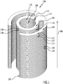
- the handle 100 comprises a base body 102 and a covering structure 104, which is arranged at least in sections at a distance from an outer circumference 116 of the base body 102.
- the base body 102 is cylindrical and embodied as a hollow body and extends along a longitudinal direction 106.
- a cavity 108 enclosed by the essentially hollow-cylindrical base body 102 preferably serves to receive a holding element (not shown here) in the form of a holder.
- the holder is preferably with the respective component on which the handle 100 is attached, connected.
- the holder is part of a tennis racket or is connected to a bicycle handlebar and / or forms part of a bicycle handlebar.
- the handle 100 has a fixing element 112 for receiving a retaining strip on an inner side 110 of the base body 102 which radially delimits the cavity 108.
- the fixing element 112 is designed in the form of a recess, in the present case in the form of a groove 114.
- the groove 114 extends in particular essentially parallel to the longitudinal direction 106 of the base body 102.
- the fixing element 112 in the present exemplary embodiment the groove 114, is preferably used to fix the handle 100 in a rotationally fixed manner on a sleeve and / or retaining strip.
- the envelope structure 104 preferably extends along the longitudinal direction 106 and is at least partially spaced apart from the base body 102 along the outer circumference 116.
- the envelope structure 104 comprises forty disk-shaped segments 117 which are arranged parallel to one another and which, with respect to their center plane 119, are arranged essentially perpendicular to the longitudinal direction 106 of the base body 102.
- the base body 102 has a plurality of disk-shaped segments 118 which are arranged parallel to one another with respect to their center plane 119 and are oriented essentially perpendicular to the longitudinal direction 106 of the base body 102.
- the handle 100 comprises forty handle elements 120, each of which is formed by a segment 117 of the envelope structure 104 and a segment 118 of the base body 102 connected to it.
- the segments 117 of the envelope structure 104 and the segments 118 of the base body 102 of a respective grip element 120 preferably each lie in a plane perpendicular to the longitudinal direction 106.
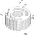
- the grip elements 120 are at least approximately disk-shaped and, in accordance with FIG Figures 1 to 3 Variants of a grip element 120 shown here each have a substantially flat support surface perpendicular to the longitudinal direction 106. Alternative configurations of the bearing surfaces perpendicular to the longitudinal direction are described in more detail below (cf. Fig. 4 and 5 ).
- a handle 100 is arranged between two handle elements 120 adjacent in the longitudinal direction 106, in each case a, in the present case disc-shaped, spacer 122 (spacer element).
- the grip elements can be spaced apart from one another in the longitudinal direction 106 by means of one or more projections (not shown).
- a modification of a handle element 120 'of a handle 100' is shown.
- a tongue 124b 'of the two tongues 124a', 124b 'of the grip element 120' has a wave shape in its course along the central plane 119 'and perpendicular to the longitudinal direction 106.
- the waves extend radially (132) away from a central axis 130 of the base body 102 '.
- the wave-shaped tongue 124b ' is composed of several elements which are circular in cross section and which are connected to one another in a materially bonded manner.
- the undulating tongue 124b ' can be made in one piece.
- both tongues 124a ', 124b' and / or the base body 102 'and / or the anchoring element 123' are wave-shaped.
- the waves or, if appropriate, spikes can also be aligned parallel to one another.
- two handle elements 120 adjacent in the longitudinal direction 106 are arranged in direct physical contact with one another in the assembled state of the handle 100.
- segment 118 of the base body 102 is essentially annular and is connected to the segment 117 of the envelope structure 104 via an anchoring element 123.
- the segment 118 of the base body 102 is formed in one piece with the segment 117 of the envelope structure 104 and the anchoring element 123.
- segment 118 of the base body 102 in the area of the anchoring element 123 is connected to the segment 117 of the envelope structure 104 in a materially and / or non-positively and / or form-fitting manner, for example by being plugged into one another and / or clipped into one another.
- the respective segments of the envelope structure 104 preferably include two tongues 124a, 124b, which extend in the circumferential direction 126 away from the anchoring element 123 in opposite circumferential directions.
- the tongues 124a, 124b are preferably at least approximately partially circular and are arranged at a distance from the segments 118 of the base body 102.
- the tongues 124a, 124b preferably each extend over approximately 90 ° or more, for example 130 ° or more, along the circumferential direction 126.
- the tongues 124a, 124b preferably each extend over approximately 160 ° or less, for example 150 ° or less, of a circular arc running along the circumferential direction 126.
- the grip elements 120 of the handle 100 preferably comprise one or more of the following plastic materials: thermoplastics, preferably polyesters, in particular polylactides, polycaprolactones and / or polyethylene terephthalate (PET), styrene polymers, polyamides, polyoxymethylene (POM) and / or polyketones, thermoplastic elastomers, reactive Resins, preferably polyurethanes, epoxy compounds and / or silicones, and other thermoplastically processable polymers.
- thermoplastics preferably polyesters, in particular polylactides, polycaprolactones and / or polyethylene terephthalate (PET), styrene polymers, polyamides, polyoxymethylene (POM) and / or polyketones, thermoplastic elastomers, reactive Resins, preferably polyurethanes, epoxy compounds and / or silicones, and other thermoplastically processable polymers.
- the handle elements 120 comprise other reactive, non-thermoplastic polymers which have comparable mechanical properties.
- the plastic material of the grip elements 120 comprises one or more of the following fillers: reinforcing fibers, in particular Carbon fibers, glass fibers, wollastonite and / or natural fibers, dyes, pigments, minerals, glass spheres, hollow glass spheres, fillers based on natural raw materials, in particular cork and / or wood flour, stabilizers, in particular UV and / or heat stabilizers, and impact modifiers.
- the plastic material of the grip element 120 comprises the filler in particular in a proportion of 65% by weight or less, for example 55% by weight or less.
- the handle elements 120 are made of polylactide and comprise dyes in a proportion of approx. 2% by weight. Sufficiently good colorations of the handle elements 120 can also be achieved with dye proportions in a range from approx. 0.1% by weight to approx. 10% by weight.
- the grip elements 120 are provided with a surface coating, for example made of polyurethane or silicone compounds. This serves in particular to optimize the feel of the handle 100.
- forces acting perpendicularly or obliquely to the longitudinal direction 106 can be resiliently absorbed by the tongues 124a, 124b.
- the tongues 124a, 124b act in the present case in a load-distributing manner.
- the tongues 124a, 124b are preferably moved towards the base body 102 when a force is applied. If the force decreases, the tongues 124a, 124b return to the normal position.
- the tongues 124a, 124b preferably lie on an arc of a circle which is concentric with the central axis of the base body 102.
- the plastic material of the grip elements 120 preferably has a modulus of elasticity of approx. 300 MPa or more, in particular approx. 1,000 MPa or more.
- the plastic material of the grip elements 120 has a modulus of elasticity of approximately 15,000 MPa or less, in particular of approximately 3,500 MPa or less.
- the modulus of elasticity is determined in a tensile test according to ISO 527.
- the desired spring effect can be achieved in the present case by means of plastic materials with an elastic modulus in the aforementioned areas.
- a grip element 120 is manufactured using a plurality of polymers.
- one or more grip elements 120 can be reinforced by insert elements made of other materials, for example metals and / or a fiber composite, in particular a carbon fiber composite.
- the insert elements are preferably enclosed by the plastic material of the grip element or embedded in it.
- the individual grip elements 120 are preferably materially connected to one another by applying a double-sided adhesive tape, for example a pressure-sensitive or hot-melt adhesive.
- a double-sided adhesive tape for example a pressure-sensitive or hot-melt adhesive.
- the grip elements 120 are connected to one another in a form-fitting and / or force-fitting manner.
- the handle 100 and / or its handle elements 120 are preferably manufactured in an additive manufacturing process, in the present case a 3D printing process.
- the handle 100 and / or its grip elements 120 are manufactured completely or partially by injection molding, machining and / or punching or can be processed subsequently by the above-mentioned methods.
- an outer radius of a grip element 120 is in the range of approximately 1 cm and approximately 7 cm, in particular approximately 2 cm and approximately 4 cm.
- FIG. 6 The variant shown of a grip element 150 essentially differs from that in FIG Figures 1 to 3 shown variant of a grip element 120 that the grip element 150 and a handle 140 formed therefrom comprise a plurality of functional elements 160.
- the grip element 150 comprises a segment 148 of a base body 162 and a segment 147 of a covering structure 164 of the handle 140.
- the essentially ring-shaped segment 148 of the base body 162 is connected to the segment 147 of the envelope structure 164 via an anchoring element 166, the grip element 150 preferably being formed in one piece.
- the grip element 150 has according to the in Figure 6
- the variant shown has two tongues 168a, 168b which extend symmetrically away from the anchoring element 166 and / or in particular are arranged at a uniform distance from the base body 162.
- a volume is created radially between the two tongues 168a, 168b and the base body 162, in particular on an outer circumference 170 of the base body 162, into which one or both of the tongues 168a, 168b can deflect when a force is applied perpendicular to the longitudinal direction 106.
- two functional elements 160 are arranged on a straight line which extends radially away from the longitudinal direction 106.
- the functional elements 160 are preferably arranged facing each other in the volume formed between a tongue 168b and the base body 162, with one functional element 160a being arranged on the tongue 168b and another functional element 160b being arranged on the outer circumference 170 of the base body 162 is.
- a further, third functional element 160c is arranged on the tongue 168a facing away from the base body 162.
- the functional elements 160a, 160b, 160c are, for example, sensor elements which can be controlled and / or evaluated by means of electrical lines (not shown).
- the electrical lines are preferably partially or completely embedded in the plastic material of the grip element 150 and / or enclosed by it.
- the anchoring element 166 has a passage opening 174 in the longitudinal direction 106, through which further electrical lines, for example in the form of cables, can be guided in the assembled state of the handle 140.
- FIG. 7 The variant shown of a grip element 200 of a handle 190 differs essentially in this way from that in FIG Figures 1 to 3 shown variant of a grip element 120 that the grip element 200 comprises four tongues 202a, 202b, 202c, 202d, which are each arranged at a distance from a segment 204 of a base body 206 of the handle 190.
- two tongues 202a, 202b or 202c, 202d are formed together essentially in the form of a circular arc in a cross section perpendicular to the longitudinal direction 106.
- the grip element 200 preferably has two anchoring elements 208a, 208b, which adjoin the segment 204 of the base body 206 and connect the base body 206 with two tongues 202a, 202b and 202c, 202d, respectively.
- the four tongues 202a, 202b, 202c, 202d are according to the variant in FIG Figure 7 essentially identical in design and in the present case each extend over approximately 40 ° to approximately 80 ° of an arc of a circle which runs along the circumferential direction 126.
- Two tongues 202a, 202b and 202c, 202d each extend on both sides, i.e. in opposite directions, away from an anchoring element 208a and 208b, in circumferential direction 126.
- FIG Figure 8 The variant shown of a grip element 250 of a handle 240 differs essentially in this way from that in FIG Figure 7 shown variant of a grip element 200 that the grip element 250 has four tongues 252a, 252b, 252c, 252d, some of which have mutually different extensions in the circumferential direction 126.
- the handle element 250 comprises a segment 248 of a base body 260 of the handle 240, which is essentially ring-shaped when viewed from above, and a segment 247 of a casing structure 262 of the handle 240.
- the segment 247 of the envelope structure 262 is preferably arranged at least partially at a distance from an outer circumference 264 of the base body 260 and in the present case comprises four tongues 252a, 252b, 252c, 252d.
- two tongues 252a, 252b or 252c, 252d are fixed on the segment 248 of the base body 260 at a distance from the base body 260 via an anchoring element 266a or 266b.
- the two anchoring elements 266a, 266b are preferably arranged essentially opposite one another in a cross section perpendicular to the longitudinal direction 106 of the handle 240 on the outer circumference of the base body 260.
- two tongues 252b, 252d which are fixed to different anchoring elements 266a, 266b and whose free ends 268b, 268d are in the present case designed to face one another, have essentially identical dimensions in the circumferential direction 126.
- Two further tongues 252a, 252c, the free ends 268a, 268c of which are formed facing one another in the present case, have mutually different expansions in the circumferential direction 126.
- An extension of a first further tongue 252a in the circumferential direction 126 preferably corresponds to at least twice, in particular three times, for example four times the extension of a second further tongue 252c in the circumferential direction 126.
- the elastic deformability of a tongue preferably increases the greater its extent in the circumferential direction 126 is at a distance from the outer circumference of the base body of the handle.
- a grip element 310 of a handle 300 preferably comprises a segment 318 of a base body 312 of the handle 300 and a segment 317 of a cover structure 304 of the handle 300.
- the envelope structure 304 comprises three tongues 320a, 320b, 320c.
- two tongues 320a, 320b extend away from an anchoring element 322 and, in particular, lie in a cross section perpendicular to the longitudinal direction 106 on a common circular arc.
- the circular arc is arranged concentrically with a circular arc which is formed by an inner side of the base body 312, which is designed as a hollow body.
- the tongues 320a, 320b preferably point towards one another with their free ends 324a, 324b and are designed essentially in the form of a hollow cylinder segment.
- a tongue 320b has five times the extent or extension in the circumferential direction 126 of a further tongue 320a or more, in particular seven times the extent or more.
- the anchoring element 322 is preferably designed in the form of a connecting section and has four passage openings 328 in the form of cutouts, in the present case with a substantially circular cross section, in the longitudinal direction 106.
- the four through openings 328 are according to the in FIG Figure 9 shown variant arranged in a row, which runs in a cross section perpendicular to the longitudinal direction 106 on an arc of a circle.
- the circular arc on which the row of passage openings 328 are arranged is in the present case arranged in cross section concentrically with the circular arc along which the tongues 320a, 320b extend.
- the enveloping structure 304 comprises a further tongue 320c, which in a cross section taken perpendicular to the longitudinal direction 306 extends essentially spirally away from the segment 318 of the base body 312 and, in particular, is arranged in a spiral shape to the tongue 320b in cross section.
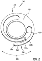
- FIG 10 Another variant of a grip element 350 of a handle 340 is shown in which two tongues 352a, 352b are provided, which extend away from an anchoring element 354 and towards one another and which overlap in an overlapping area 356 in the circumferential direction 126.
- one or more free ends 358a, 358b of the tongues 352a, 352b have thickenings and / or are formed by thickenings. This applies equally to the variants shown above. It can be favorable if the two tongues 352a, 352b are each designed essentially in the form of a hollow cylinder segment.
- the two tongues 352a, 352b are preferably spaced apart from one another and from the base body 360, which is essentially circular in a plan view, in the radial direction with respect to a central axis of a base body 360 of the handle 340.
- the two tongues 352a, 352b are preferably brought into direct material contact and shift relative to one another, in particular in such a way that the overlap area 356 increases in the circumferential direction 126 will.
- the handles 100, 140, 190, 240, 300, 340 described above are preferably produced using the method described below.
- the handle 100, 140, 190, 240, 300, 340 is preferably produced using an additive process, for example a 3D printing process.
- the handles 100, 140, 190, 240, 300, 340 comprise an essentially partially cylindrical or cylindrical base body 102, 162, 206, 260, 312, 360 with a longitudinal direction 106 and a casing structure 104, 164, 262, which essentially extends along the longitudinal direction 106 of the base body 102, 162, 206, 260, 312, 360 and along an outer circumference 116, 170 of the base body 102, 162, 206, 260, 312, 360 at least partially from the base body 102, 162, 206, 260 , 312, 360 at a distance from its outer contour, the envelope structure 104, 164, 262 comprising a plurality of segments 117, 147, 247 arranged parallel to one another, which in the Are arranged aligned essentially perpendicular to the longitudinal direction 106 of the base body 102, 162, 206, 260, 312, 360.
- Grip elements 120, 150, 190, 250, 310, 350 are preferably produced, each of which has a segment 118, 148, 204, 248, 318 of the base body 102, 162, 206, 260, 312, 360 and a segment 117, 147, 247 of the envelope structure 104, 164, 262, which lie essentially in a plane perpendicular to the longitudinal direction 106, and then joined together to form the corresponding handle.
- each handle element 120, 150, 190, 250, 310, 350 is printed individually, with a plastic material in the form of the handle element 120, 150, 190, 250, 310, advantageously using physical and / or chemical melting processes and hardening processes. 350 is built.
- selective laser sintering and / or stereolithography and / or digital light processing and / or multi jet modeling and / or multi jet fusion and / or fused deposition molding are suitable as 3D printing processes.
- the handle 100, 140, 190, 240, 300, 340 is preferably independent of one another by resilient deformation of the tongues when pressure is applied perpendicular to the longitudinal direction 106 to the shape of the hand of the user and to the respective change in the shape of the hand when the handle 100, 140, 190, 240, 300, 340 reversibly adaptable.
Landscapes
- Engineering & Computer Science (AREA)
- Mechanical Engineering (AREA)
- Health & Medical Sciences (AREA)
- General Health & Medical Sciences (AREA)
- Physical Education & Sports Medicine (AREA)
- Transportation (AREA)
- Physics & Mathematics (AREA)
- General Physics & Mathematics (AREA)
- Automation & Control Theory (AREA)
- Physiology (AREA)
- Golf Clubs (AREA)
Description
- Die Erfindung betrifft einen Handgriff gemäß dem Oberbegriff des Patentanspruchs 1, sowie ein Verfahren zu dessen Herstellung. Handgriffe kommen insbesondere als Griffe für Fahrzeuge, Sportgeräte, Waffen und Freizeiteinrichtungen und -geräte zum Einsatz.
- Aus der
DE 10 2007 009 169 A1 ist ein Handgriff bekannt, welcher einen Griffkern und eine auf dem Griffkern angeordnete Griffhülle umfasst. Die Griffhülle umfasst mindestens ein schwingungsdämpfendes Mittel sowie ein Befestigungselement, wobei das schwingungsdämpfende Mittel vorspannbar ist. - Aus der
US 2015/0292584 A1 ist eine radiale Feder für mechanische oder elektromechanische Anwendungen zur Kontrolle von radialen Kräften zwischen daran anschließenden konzentrischen Komponenten bekannt. Die radiale Feder umfasst ein Basiselement, Stützelemente und Federelemente, welche jeweils an dem Basiselement angeordnet sind. Die Federelemente sind radial verformbar. - Aus der
DE 103 10 095 A1 ist ein Griffelement für ein Handwerkzeug bekannt, welches auf einer Griffseele eines Werkzeugstieles angeordnet ist, mit einem Griffbereich und einem Griff-Endbereich, an dessen Stirnfläche ein Schutzelement befestigt ist, wobei der Griffbereich aus zahlreichen, auf der Griffseele angeordneten, vorzugsweise schwingungsdämpfenden Scheiben gebildet wird. Ein freier Endbereich der Griffseele ist mit mindestens einem Innengewinde versehen. Das Schutzelement ist als ein der Kontur des Griff-Endbereiches entsprechendes massives Endstück ausgebildet, welches dem Innengewinde gegenüberliegend eine Durchgangsbohrung aufweist, in der zur Befestigung des Endstücks an der Griffseele eine Gewindeschraube befestigbar ist, deren Kopf in eine die Durchgangsbohrung umgebende Einsenkung im Wesentlichen vollständig eintaucht. - Die
US 2,603,260 A , die einen Handgriff gemäß dem Oberbegriff des Patentanspruchs1 zeigt, offenbart ein Schlagwerkzeug, welches einen verlängerten Griff mit einem Schlagende und einem hinteren Ende umfasst. An dem Schlagende ist ein Schlagkopf angeordnet. Das Schlagwerkzeug umfasst einen nachgiebigen Abstandhalter, welcher das Schlagende umgibt, aber von dem Schlagkopf beabstandet angeordnet ist. - Aus der
DE 10 2006 061 247 A1 Handgriff, umfassend eine Griffhülle und einen Griffkern, bekannt. Der Griffkern weist an einem Ende ein Befestigungselement auf und erstreckt sich bis an das dem Befestigungselement gegenüberliegende Ende der Griffhülle. Der Handgriff umfasst ferner einen zwischen Griffhülle und Griffkern angeordneten Zwischenraum, in welchem zumindest ein Dämpfungselement vorgesehen ist. Der Griffkern bildet in der Griffhülle einen berührungslosen Hinterschnitt. - Die
DE 8 905 298 U1 offenbart eine Vorrichtung zur Steuerung von Hand für Maschinene, deren Betrieb von einem elektrischen Zustimmungssignal abhänggig ist. Die Vorrichtung umfasst einen mit der Hand umfassbaren Hohlkörper, ein zentral in dem Innenraum des Hohlkörpers angebrachtes strahlendes Element, einen Generator und eine Schwellwertdetektoreinrichtung. - Aufgabe der vorliegenden Erfindung ist es, einen Handgriff bereitzustellen, welcher an die Handform des Benutzers anpassbar ist und darüber hinaus einfach und kostengünstig herstellbar ist.
- Diese Aufgabe wird erfindungsgemäß durch einen Handgriff gemäß Anspruch 1 gelöst.
- Dadurch, dass der Handgriff neben einem im Wesentlichen zylindrischen oder teilzylindrischen Grundkörper eine Hüllstruktur umfasst, welche sich entlang der Längsrichtung des Grundkörpers und entlang dem äußeren Umfang des Grundkörpers zumindest teilweise beabstandet von dem Grundkörper erstreckt und zumindest partiell elastisch verformbar ist, kann eine Anpassung des Handgriffs an die Hand des Benutzers, welche sich um den Handgriff schließt, realisiert werden. Dies erhöht die Benutzerfreundlichkeit in erheblichem Maße.
- Die zumindest teilweise Beabstandung der Hüllstruktur von dem Grundkörper des Handgriffs, d.h. von dessen äußerem Umfang, und die Ausbildung von mehreren Segmenten in der Hüllstruktur, welche im Wesentlichen senkrecht zur Längsrichtung ausgebildet sind, ergeben eine zusätzlich verbesserte Anpassbarkeit des Handgriffs an die Hand des Benutzers.
- Darüber hinaus kann im Vergleich zu Handgriffen aus einem Vollmaterial aufgrund der Beabstandung zwischen dem Grundkörper und der Hüllstruktur Material eingespart werden, wodurch eine kostengünstigere Herstellung möglich ist.
- Günstig ist es, wenn der Handgriff mehrere in Längsrichtung aufeinander folgende Griffelemente umfasst, wobei dann der Grundkörper ebenfalls in Segmente unterteilt ist.
- So sind die einzelnen Griffelemente insbesondere separat herstellbar und können je nach Bedarf und Anforderungen angepasst werden. Insbesondere können die physikalischen Eigenschaften, wie beispielsweise der E-Modul und/ oder die Härte, und/oder optische Eigenschaften, wie beispielsweise Farbe, der einzelnen Griffelemente unabhängig voneinander je nach Anforderungen und/ oder Wunsch des Benutzers angepasst werden. Auch kann ein Griffelement ein Segment des Grundkörpers und ein oder mehrere Segmente der Hüllstruktur umfassen.
- Alternativ kann vorgesehen sein, dass der Handgriff einstückig hergestellt ist. Dies kann bei der Produktion von Serienmodellen von Vorteil sein, da erhöhte Stückzahlen ohne Anpassung der Produktionsparameter hergestellt werden können.
- Die Hüllstruktur umfasst vorzugsweise zehn Segmente oder mehr, insbesondere zwanzig Segmente oder mehr, beispielsweise dreißig Segmente oder mehr. Diese Anzahl an Segmenten kann ausreichend sein, um eine verbesserte Variierbarkeit eines äußeren Umfangs der einzelnen Segmente zu ermöglichen.
- Vorzugsweise umfasst die Hüllstruktur sechzig Segmente oder weniger, insbesondere fünfzig Segmente oder weniger, beispielsweise vierzig Segmente oder weniger. Durch diese Anzahl kann eine sehr genaue Anpassung des Handgriffs an die Handform des Benutzers beim Umschließen des Handgriffs vorgenommen werden und gleichzeitig ist der Handgriff insbesondere mit vertretbarem Aufwand herstellbar.
- Für die Herstellung und Handhabbarkeit des Handgriffs ist es vorteilhaft, wenn die Hüllstruktur und/oder der Grundkörper des Handgriffs aus einem Kunststoffmaterial hergestellt ist/sind. So kann der Handgriff mit einem verringerten Gewicht im Vergleich zu Handgriffen aus metallischen Materialien hergestellt werden.
- Es kann vorgesehen sein, dass die mehreren Segmente der Hüllstruktur im Wesentlichen scheibenförmig sind. Dies erleichtert eine Aneinanderreihung, insbesondere eine passgenaue Aneinanderreihung, der mehreren Segmente der Hüllstruktur in Längsrichtung des Grundkörpers.
- "Scheibenförmig" bedeutet von der Zylinderform abgeleitet, wobei ein Radius des Umfangs des Segments insbesondere um ein Vielfaches größer ist als seine Dicke in Längsrichtung des Grundkörpers gesehen. "Scheibenförmig" umfasst vorzugsweise auch plattenförmige Segmente und/oder Ringsegmente. Insbesondere umfasst "scheibenförmig" auch Segmente, welche senkrecht zur Längsrichtung bereichsweise oder vollständig einen wellenförmigen oder zackenförmigen Querschnitt aufweisen, sofern ihre Mittelebene im Wesentlichen senkrecht zur Längsrichtung des Grundkörpers angeordnet ist.
- Insbesondere liegen im Falle von im Wesentlichen scheibenförmigen Segmenten der Hüllstruktur im Wesentlichen ebene Flächen von in Längsrichtung des Grundkörpers aneinander angrenzenden Segmenten direkt aneinander an.
- Alternativ können die Segmente der Hüllstruktur voneinander beabstandet angeordnet sein, worauf nachfolgend noch eingegangen werden wird.
- Günstig ist es, wenn eine Außenfläche mindestens eines Segments, insbesondere von mehreren oder auch von sämtlichen Segmenten der Hüllstruktur, in einem Querschnitt senkrecht zur Längsrichtung im Wesentlichen kreisförmig oder im Wesentlichen teilkreisförmig ist. So kann der Handgriff komfortabel und benutzerfreundlich umgriffen werden.
- Zumindest eines der mehreren, insbesondere sämtliche, Segmente der Hüllstruktur weist eine oder mehrere Zungen auf, welche vorzugsweise vollständig oder teilweise von dem äußeren Umfang des Grundkörpers beabstandet angeordnet sind. Vorzugsweise sind die Zungen elastisch am Grundkörper gehalten und/oder als solche elastisch verformbar ausgebildet.
- Zur symmetrischen Anordnung der Zungen bezüglich einer Symmetrieachse parallel zur Längsrichtung des Grundkörpers ist es günstig, wenn das mindestens eine Segment, insbesondere mehrere oder auch sämtliche Segmente, eine gerade Anzahl von Zungen aufweist.
- Vorzugsweise ist ein freies Ende oder sind freie Enden der einen oder der mehreren Zungen jeweils abgerundet. Dies macht sich haptisch vorteilhaft bemerkbar.
- Insbesondere weist zumindest eines der mehreren, insbesondere mehrere oder auch sämtliche Segmente der Hüllstruktur zwei bis vier Zungen auf, welche vollständig oder teilweise von dem äußeren Umfang des Grundkörpers beabstandet angeordnet sind.
- Die eine oder die mehreren Zungen sind insbesondere in Form eines Hohlzylindersegments ausgebildet.
- Es kann vorgesehen sein, dass zumindest eine der Zungen in ihrem Verlauf senkrecht zur Längsrichtung wellenförmig oder zackenförmig ausgebildet ist. Dies kann zu einer Beabstandung benachbarter Segmente in Längsrichtung genutzt weden, womit eine optimierte Belüftung des Handgriffs realisiert werden kann.
- Der Abstand zwischen Segmenten in Längsrichtung des Grundkörpers ist dabei durch die Anordnung der Wellen oder Zacken eines Segments in Umfangsrichtung relativ zu der Anordnung der Wellen oder Zacken eines im zusammengebauten Zustand in Längsrichtung benachbarten Segments einstellbar. So ist beispielsweise der Abstand in Längsrichtung maximiert, wenn im zusammengebauten Zustand des Handgriffs bei benachbarten Segmenten in Längsrichtung Wellenberg und Wellental bzw. Zackenberg und Zackental aneinander angrenzen. Die Anordnung der Wellen oder Zacken in Umfangsrichtung ist bei der Herstellung der Segmente bzw. bei deren Konstruktion wählbar. Je nachdem, wie weit die Wellen bzw. Zacken benachbarter Segmente ineinander greifen, findet eine mehr oder weniger ausgeprägte Stabilisierung der Hüllstruktur statt. Damit lässt sich die Haptik des Handgriffs weiter optimieren.
- Darüber hinaus kann durch Zungen mit wellenförmigem oder zackenförmigem Querschnitt die Torsionssteifigkeit der Segmente selbst erhöht sein.
- Bei den erwähnten Ausführungsformen sind die Wellen bzw. Zacken vorzugsweise parallel zueinander orientiert oder erstrecken sich strahlenförmig von einer Mittelachse des Grundkörpers weg.
- Bereiche, welche parallel zur Längsrichtung gesehen einen wellenförmigen oder zackenförmigen Querschnitt aufweisen, sind vorzugsweise aus einzelnen im Querschnitt kreisbogen- bzw. zackenförmigen Elementen zusammengesetzt, die stoffschlüssig miteinander verbunden sind.
- Alternativ sind die Bereiche, welche einen wellenförmigen oder zackenförmigen Querschnitt aufweisen, einstückig hergestellt.
- Die eine oder die mehreren, insbesondere zwei bis vier, Zungen sind mittels eines oder mehrerer Verankerungselemente an dem Grundkörpers des Handgriffs festgelegt.
- Insbesondere erstrecken sich zwei Zungen der Hüllstruktur beidseitig von jeweils einem Verankerungselement in entgegengesetzten Umfangsrichtungen des Handgriffs von dem Verankerungselement weg.
- Bei Ausführungsformen mit einem Verankerungselement weist das eine Verankerungselement in Längsrichtung des Grundkörpers vorzugsweise mindestens eine Durchtrittsöffnung auf.
- Bei Ausführungsformen mit mehreren Verankerungselementen weist insbesondere mindestens eines der mehreren Verankerungselemente in Längsrichtung des Grundkörpers mindestens eine Durchtrittsöffnung auf.
- Mittels der mindestens einen Durchtrittsöffnung kann zum einen eine verbesserte Belüftung des Handgriffs erzielt werden. Zum anderen kann bei Griffelementen, die aus elastischen Materialien gefertigt sind, mittels der mindestens einen Durchtrittsöffnung eine federelastische Nachgiebigkeit des Griffelements senkrecht zur Längsrichtung des Handgriffs und damit eine verbesserte Anpassbarkeit des Handgriffs an die Hand des Benutzers auch im Bereich des oder der Verankerungselemente realisiert werden.
- Die eine oder mehrere in Längsrichtung verlaufende Durchtrittsöffnungen der Verankerungselemente können ferner zum einen der Aufnahme von Funktionselementen dienen und/oder die Haptik des Handgriffs weiter optimieren.
- Es kann vorgesehen sein, dass die eine oder die mehreren Zungen in einem Querschnitt senkrecht zur Längsrichtung des Grundkörpers spiralförmig und/ oder helixförmig bezüglich des äußeren Umfangs des Grundkörpers ausgebildet sind.
- Alternativ verlaufen die eine oder die mehreren Zungen konzentrisch zur Mittelachse des Grundkörpers.
- Es kann vorgesehen sein, dass das Verankerungselement einteilig ausgebildet ist und insbesondere einstückig mit dem Grundkörper und/oder einstückig mit der Hüllstruktur, insbesondere der einen oder den mehreren Zungen, hergestellt ist.
- Alternativ kann vorgesehen sein, dass das Verankerungselement zweiteilig ausgebildet ist und ein erstes und ein zweites Teil umfasst. Das erste Teil ist vorzugsweise stoffschlüssig, insbesondere einstückig, mit dem Grundkörper des Handgriffs oder dessen Segment ausgebildet. Das zweite Teil ist vorzugsweise stoffschlüssig, insbesondere einstückig, mit dem jeweiligen Segment der Hüllstruktur ausgebildet.
- Das erste und das zweite Teil des Verankerungselements sind vorzugsweise stoffschlüssig und/oder kraftschlüssig und/oder formschlüssig miteinander verbunden.
- Beispielsweise ist das erste Teil des Verankerungselements in das zweite Teil des Verankerungselements eingeclipst oder umgekehrt.
- Wie schon erwähnt kann vorgesehen sein, dass die eine oder die mehreren Zungen federelastisch an dem Grundkörper des Handgriffs festgelegt sind, wobei die eine oder die mehreren Zungen, insbesondere unabhängig voneinander, elastisch verformbar zur Aufnahme von Kräften, welche quer oder senkrecht zur Längsrichtung des Grundkörpers wirken, ausgebildet sind. So kann eine erleichterte und situationsbedingte Anpassung der Form des Handgriffs realisiert werden und darüber hinaus eine komfortable und benutzerfreundliche Verwendung des Handgriffs gewährleistet werden.
- Beispielsweise neigen sich Zungen, welche in einem Bereich angeordnet sind, in welchem Kräfte, insbesondere Druckkräfte, in Richtung des Grundkörpers auf sie einwirken, zum Grundkörper hin, während die übrigen Zungen nicht oder weniger verformt werden und gegebenenfalls in einer Normalstellung verbleiben. Wenn keine Druckkräfte mehr wirken, kehren die geneigten und/ oder elastisch verformten Zungen in die Normalstellung zurück.
- Die "Normalstellung" bezeichnet vorzugsweise eine Position der Zungen ohne Beaufschlagung mit quer oder senkrecht zur Längsrichtung wirkenden Kräften.
- Vorteilhaft kann es sein, wenn die mehreren Segmente der Hüllstruktur zwei oder mehrere Zungen umfassen, welche sich im Wesentlichen entlang der Umfangsrichtung des Handgriffs erstrecken, wobei sich zumindest zwei der zwei oder der mehreren Zungen in einem Überlappungsbereich entlang der Umfangsrichtung überlappen und/oder einander übergreifen. So kann eine Kraftaufnahme durch die zwei oder die mehreren Zungen und gleichzeitig eine Stabilisierung des Handgriffs ermöglicht werden.
- Vorzugsweise erstreckt sich der Überlappungsbereich über einen Bereich von ca. 10° bis ca. 180°, insbesondere ca. 20° bis ca. 90°, eines Kreisbogens, welcher längs der Umfangsrichtung des Handgriffs verläuft.
- Die eine oder die mehreren Zungen erstrecken sich vorzugsweise über ca. 40° bis ca. 160°, insbesondere ca. 90° bis ca. 150°, eines Kreisbogens, welcher längs der Umfangsrichtung des Grundkörpers verläuft.
- Der Handgriff kann auch insgesamt in mehrere Griffelemente unterteilt sein, welche in Längsrichtung des Grundkörpers hintereinander angeordnet sind, wobei die mehreren Griffelemente jeweils ein Segment des Grundkörpers und ein Segment der Hüllstruktur umfassen, wobei das Segment des Grundkörpers und das Segment der Hüllstruktur im Wesentlichen in einer Ebene senkrecht zur Längsrichtung des Grundkörpers liegen. Dies kann den Zusammenbau des Handgriffs und dessen Handhabbarkeit erleichtern.
- Einzelne oder mehrere der im Zusammenhang mit den mehreren Segmenten der Hüllstruktur beschriebenen Merkmale und/oder Vorteile gelten vorzugsweise für die Griffelemente insgesamt, d.h. einschließlich der Segmente des Grundkörpers, gleichermaßen.
- Insbesondere können auch die Segmente des Grundkörpers oder zumindest Teile davon im Verlauf senkrecht zur Längsrichtung wellenförmig oder zackenförmig ausgebildet sein.
- Es kann vorgesehen sein, dass der Handgriff ein oder mehrere Abstandhalterelemente umfasst, welche in Längsrichtung des Grundkörpers jeweils zwischen zwei Griffelementen angeordnet sind. So kann zum einen Material eingespart werden und zum anderen eine Belüftung des Handgriffs zwischen den Griffelementen ermöglicht werden. Darüber hinaus kann so eine Verformung einzelner Segmente der Hüllstruktur unabhängig voneinander aufgrund verringerter Reibung zwischen benachbarten Segmenten der Hüllstruktur erleichtert werden.
- Eine Belüftung des Handgriffs ist vorzugsweise derart realisiert, dass die Segmente der Hüllstruktur, gegebenenfalls die Griffelemente insgesamt in einem vorgegebenen Abstand voneinander angeordnet sind.
- Ergänzend oder alternativ kann auch durch eine Anpassung der Geometrie der Griffelemente ein Abstand in Längsrichtung ermöglicht werden. Beispielsweise weist eines oder mehrere der mehreren Griffelemente einen oder mehrere Vorsprünge in Längsrichtung auf, wodurch vorzugsweise ein in Längsrichtung benachbartes Griffelement von diesem Griffelement beabstandet ist. Der eine oder die mehreren Vorsprünge sind beispielsweise Strukturelemente in Form von Rippenelementen.
- Es kann vorgesehen sein, dass eines oder mehrere Griffelemente einen im Wesentlichen wellenförmigen Querschnitt parallel zur Längsrichtung aufweisen.
- Die Griffelemente des Handgriffs sind vorzugsweise einstückig gefertigt.
- Alternativ sind die Griffelemente mehrteilig ausgebildet. Bei Ausführungsformen mit mehrteiligen Griffelementen können das Segment des Grundkörpers und das Segment der Hüllstruktur als separate Teile ausgebildet sein. Es kann auch vorgesehen sein, dass das Segment des Grundkörpers, das Verankerungselement und/oder die eine oder die mehreren Zungen jeweils separat hergestellte Teile sind.
- Die unterschiedlichen Teile eines Griffelements sind insbesondere stoffschlüssig und/oder formschlüssig und/oder kraftschlüssig, beispielsweise durch Ineinanderstecken und/oder Ineinanderclipsen, miteinander verbunden. So kann eine drehfeste Verbindung realisiert werden.
- Ergänzend oder alternativ sind die Teile der Griffelemente unter Verwendung eines Haft- und/oder Schmelzklebers miteinander verbunden.
- Da die Griffelemente als separate Bauteile hergestellt sind, können die Griffelemente insbesondere mit unterschiedlichen physikalischen und/oder optischen Eigenschaften zu einem Handgriff kombiniert werden.
- Auch können Griffelemente aus voneinander verschiedenen Kunststoffmaterialien in einem Handgriff verwendet werden. So kann der Handgriff in Längsrichtung unterschiedliche Festigkeiten aufweisen und/oder die Optik und/oder Haptik kann in Längsrichtung variieren.
- Es kann vorgesehen sein, dass die Griffelemente stoffschlüssig und/oder kraftschlüssig und/oder formschlüssig miteinander verbunden sind. Insbesondere lassen sich die Griffelemente miteinander verkleben. Beispielsweise kann vorgesehen sein, dass durch ein zumindest partielles Anschmelzen und/oder Verschmelzen von in Längsrichtung des Grundkörpers aneinander angrenzenden Griffelementen ein Stoffschluss realisiert wird.
- Alternativ oder ergänzend kann vorgesehen sein, dass jeweils ein Segment des Grundkörpers und ein Segment der Hüllstruktur kraftschlüssig und/oder stoffschlüssig und/oder formschlüssig als Teile der Griffelemente miteinander verbunden sind.
- Vorzugsweise sind der Grundkörper oder dessen Segmente und/oder die Hüllstruktur oder deren Segmente unter Verwendung eines additiven Verfahrens, insbesondere unter Verwendung eines 3D-Druckverfahrens, hergestellt. Dies kann eine auf den Kunden angepasste Herstellung des Handgriffs ermöglichen.
- Alternativ oder ergänzend kann vorgesehen sein, dass der Grundkörper oder dessen Segmente und/oder die Hüllstruktur oder deren Segmente zumindest teilweise mittels Zerspanen und/oder Spritzgießen und/oder Ausstanzen hergestellt sind.
- Beispielsweise ist der Grundkörper durch Spritzgießen hergestellt und die Hüllstruktur ist in einem 3D-Druckverfahren hergestellt.
- Vorzugsweise hat der Grundkörper in einem Querschnitt senkrecht zur Längsrichtung eine Polygon-Form, wobei das Polygon insbesondere fünf Ecken oder mehr aufweist.
- Insbesondere weist der Grundkörper in dem Querschnitt senkrecht zur Längsrichtung im Wesentlichen mittig eine Ausnehmung in Polygon-Form auf, wobei das Polygon insbesondere fünf Ecken oder mehr aufweist.
- Es kann vorgesehen sein, dass der Grundkörper zumindest teilweise und/oder mindestens eines der mehreren Segmente der Hüllstruktur jeweils aus einem Kunststoffmaterial hergestellt ist/sind, wobei das Kunststoffmaterial eines oder mehrere der folgenden Polymere umfasst: thermoplastische Kunststoffe, vorzugsweise Polyester, insbesondere Polylactide, Polycaprolactone und/oder Polyethylenterephthalat (PET), Styrolpolymere, Polyamide, Polyoxymethylene (POM) und/oder Polyketone; thermoplastische Elastomere; reaktive Harze, vorzugsweise Polyurethane; Epoxy-Verbindungen und/oder Silikone und weitere thermoplastisch verarbeitbare Polymere.
- Thermoplastische Kunststoffe bieten in der Regel den Vorteil einer einfachen Verarbeitbarkeit der daraus hergestellten Elemente.
- Polylactide sind insbesondere gut in einem 3D-Druckverfahren, beispielsweise einem sogenannten FFM (Fused Filament Modeling) Verfahren, verarbeitbar.
- Es können auch reaktive Polymere, welche nicht-thermoplastische Formmassen mit vergleichbaren mechanischen Eigenschaften ergeben, zur teilweisen oder vollständigen Herstellung des Grundkörpers oder mindestens eines der mehreren Segmente der Hüllstruktur verwendet werden.
- Der Grundkörper und mindestens eines der mehreren Segmente der Hüllstruktur können aus unterschiedlichen Kunststoffmaterialien hergestellt sein. Damit können die Eigenschaften des Grundkörpers und des mindestens einen der mehreren Segmente für die ihre unterschiedlichen Funktionen optimiert werden.
- Alternativ kann vorgesehen sein, dass der Grundkörper und die mehreren Segmente aus identischen Kunststoffmaterialien hergestellt sind. Vorzugsweise umfasst das Kunststoffmaterial einen oder mehrere der folgenden Füllstoffe: Verstärkungsfasern, insbesondere Kohlenstofffasern, Glasfasern, Wollastonit und/oder Naturfasern, Farbstoffe, Pigmente, Mineralstoffe, Glaskugeln, Glashohlkugeln, auf natürlichen Rohstoffen basierte Füllstoffe, insbesondere Kork und/oder Holzmehl; Stabilisatoren, insbesondere UV- und/ oder Hitze-Stabilisatoren, und Schlagzähmodifier.
- Durch eine Verwendung von einem oder mehreren Füllstoffen kann der Handgriff oder Teile davon an die individuellen Anforderungen und/oder an die individuellen Wünsche des Benutzers angepasst werden. Beispielsweise kann durch Verstärkungsfasern die Stabilität der jeweiligen Elemente des Handgriffs verbessert werden und/oder kann beispielsweise die Verwendung von Farbstoffen ein individueller Farbwunsch eines Benutzers realisiert werden. Durch die Verwendung von unterschiedlichen Farbstoffen und/oder Farbstoffen in unterschiedlich hohem Anteil in unterschiedlichen Elementen kann beispielsweise ein Muster innerhalb des Handgriffs und/oder ein Farbverlauf realisiert werden.
- Durch den Zusatz von Mineralstoffen lässt sich vorzugsweise eine durch den E-Modul bestimmbare Steifigkeit einstellen.
- Die Verwendung von Glashohlkugeln führt zu einer reduzierten Dichte im Vergleich zu einem Material ohne diesen Füllstoff und so zu einem reduzierten Gewicht des Handgriffs.
- Vorzugsweise umfasst das Kunststoffmaterial des Grundkörpers und/oder mindestens eines der mehreren Segmente den einen Füllstoff oder die mehreren Füllstoffe insgesamt in einem Anteil von ca. 65 Gew.-% oder weniger, insbesondere ca. 55 Gew.-% oder weniger. Der Anteilswert ist auf das Gesamtgewicht der Zusammensetzung bezogen und umfasst alle eingesetzten Füllstoffe. Bei den zuvor genannten Anteilen ist insbesondere noch eine gute Verarbeitbarkeit des Kunststoffmaterials gegeben und gleichzeitig sind insbesondere die Eigenschaften des Kunststoffmaterials in weiten Grenzen und unter verschiedenen Gesichtspunkten optimierbar.
- Es kann vorgesehen sein, dass das Kunststoffmaterial eine weiche Polymer- oder Elastomer-Komponente und eine harte Polymer-Komponente umfasst.
- Die weiche Polymer- oder Elastomer-Komponente weist insbesondere einen E-Modul von ca. 100 MPa bis ca. 1.500 MPa auf. Beispielsweise umfasst die weiche Komponente Kautschuk und/oder ein thermoplastisches Elastomer oder ist daraus gebildet.
- Die harte Polymer-Komponente weist insbesondere einen E-Modul von ca. 1.500 MPa bis ca. 15.000 MPa auf. Beispielsweise umfasst die harte Komponente ein Polylactid oder ist daraus gebildet.
- Es kann vorgesehen sein, dass eine Oberfläche des Grundkörpers und/oder eine Oberfläche mindestens eines der Segmente der Hüllstruktur vollständig oder zumindest teilweise mit einer Beschichtung versehen ist. Die Beschichtung umfasst insbesondere Polyurethanmaterialien und/oder Silikon-Verbindungen. So kann eine verbesserte Griffigkeit des Handgriffs oder von Teilen davon erreicht werden.
- Zur verbesserten Kraftaufnahme von auf den Handgriff wirkenden Kräften ist es günstig, wenn die Kunststoffmaterialien des Grundkörper und/oder des mindestens eines der Segmente der Hüllstruktur einen nach ISO 527 bestimmten E-Modul in einem Bereich von ca. 300 MPa und ca. 15.000 MPa, vorzugsweise in einem Bereich von ca. 1.000 MPa und ca. 3.500 MPa, aufweisen. Dies resultiert in einer verbesserten Handhabbarkeit des Handgriffs. Der E-Modul wird in einem Zugversuch nach ISO 527 bestimmt.
- Vorteilhaft ist es, wenn der Grundkörper und/oder die Hüllstruktur, vorzugsweise mindestens eines der Segmente der Hüllstruktur, ein oder mehrere Einlageelemente umfassen, welche von einem Material des Grundkörpers und/ oder einem Material der Hüllstruktur umschlossen oder in dieses eingebettet ist/sind, wobei das eine oder die mehreren Einlageelemente insbesondere einen Faserverbund, insbesondere einen Kohlenstofffaserverbund, beispielsweise ein Roving oder eine Fasermatte, umfassen. So kann eine optimierte Formstabilität des Grundkörpers und/oder der Hüllstruktur erreicht werden.
- Vorzugsweise weist zumindest eines der Griffelemente eines oder mehrere konstruktive Strukturelemente auf, durch welche die mechanischen Eigenschaften des entsprechenden Griffelements angepasst werden können. Konstruktive Strukturelemente sind insbesondere Rippenelemente, Wabenelemente, Aussparungen und/oder Hohlräume.
- Es kann vorgesehen sein, dass der Handgriff ein Endelement umfasst, welches eine Bewegung des Grundkörpers und/oder der Hüllstruktur in Längsrichtung und/oder in Umfangsrichtung begrenzt. Das Endelement ist beispielsweise von einem mit dem Handgriff zu bedienenden Bauteil abgewandt angeordnet.
- Das Endelement begrenzt vorzugsweise eine Verschieblichkeit des Grundkörpers und/oder der Hüllstruktur in Längsrichtung. Insbesondere kann das Endelement eine Drehbarkeit des Grundkörpers und/oder der Hüllstruktur in Umfangsrichtung begrenzen.
- Vorzugsweise ist das Endelement als eine Endscheibe oder als ein Endknopf ausgebildet.
- Der Grundkörper ist vorzugsweise im Wesentlichen hohlzylindrisch oder teilhohlzylindrisch ausgebildet und umfasst einen Hohlraum zur Aufnahme eines Halteelements, wobei das Halteelement insbesondere eine Hülse ist. So kann eine stabile Festlegung des Grundkörpers und gegebenenfalls von dessen Segmenten und/oder der Segmente der Hüllstruktur realisiert werden.
- Es kann vorgesehen sein, dass die Hülse mit einem elastischen Kunststoffmaterial überzogen ist, und aufgeschobene Griffelemente des Handgriffs aufgrund von Wechselwirkungen, beispielsweise Reibungskräften und/oder adhäsiven Wechselwirkungen, mit dem elastischen Kunststoffmaterial drehfest an der Hülse festgelegt sind.
- Ergänzend oder alternativ kann es vorteilhaft sein, wenn die Griffelemente in Längsrichtung jeweils eine Durchtrittsöffnung aufweisen, deren Innendurchmesser im Vergleich zu einem Außendurchmesser eines Halteelements ein Untermaß aufweist. Die Griffelemente sind insbesondere durch mechanischen Druck auf das Halteelement aufschiebbar und nach dem Aufschieben, beispielsweise durch Reibungskräfte, fixiert.
- Günstig ist es, wenn an einer einen Hohlraum vollständig oder teilweise umgebenden Innenseite des Grundkörpers mindestens ein Fixierelement des Handgriffs zur Fixierung einer Position des Grundkörpers entlang der Umfangsrichtung des Grundkörpers angeordnet ist.
- Die den Hohlraum vollständig oder teilweise umgebende Innenseite weist vorzugsweise eine im Wesentlichen zylindrische oder teilzylindrische Form auf.
- Alternativ weist die Innenseite einen im Wesentlichen polygonen Querschnitt senkrecht zur Längsrichtung auf, wobei das Polygon insbesondere fünf Ecken oder mehr aufweist.
- Das Fixierelement ist vorzugsweise ein Rücksprung, beispielsweise eine Nut.
- Alternativ kann vorgesehen sein, dass das Fixierelement als Vorsprung ausgebildet ist, beispielsweise als Leiste, welche in einen komplementär ausgebildeten Rücksprung des Halteelements eingreift.
- Für eine platzsparende Unterbringung von weiteren Funktionen kann es vorteilhaft sein, wenn der Handgriff ein oder mehrere funktionale Elemente umfasst, welche insbesondere in den Grundkörper und/oder die Hüllstruktur integriert sind.
- Ergänzend oder alternativ kann vorgesehen sein, dass ein oder mehrere funktionale Elemente außerhalb des Grundkörpers und/oder außerhalb der Hüllstruktur verlaufend angebracht sind.
- Das eine oder die mehreren funktionalen Elemente sind vorzugsweise durch Druck senkrecht zur Längsrichtung betätigbar.
- Die funktionalen Elemente können mechanische Elemente, vorzugsweise Elemente einer Bremsvorrichtung und/oder Elemente eines Richtungsanzeigers, insbesondere eine Blinkvorrichtung, und/oder Elemente einer Belüftungsvorrichtung, insbesondere in Form von Aussparungen, und/oder Sensorelemente umfassen.
- Beispielsweise können Elemente einer Bremsvorrichtung eines Fahrrads in und/oder an dem Grundkörper und/oder der Hüllstruktur des Handgriffs festgelegt sein.
- Mittels eines oder mehrerer Sensorelemente können beispielsweise bei einer Verwendung des Handgriffs biometrische Werte des Benutzers, wie beispielsweise Temperatur und/oder Puls, ermittelt werden.
- Die Erfindung betrifft ferner ein Verfahren zur Herstellung eines erfindungsgemäßen Handgriffs.
- Diesbezüglich liegt der Erfindung die Aufgabe zugrunde, ein Verfahren bereitzustellen, mittels welchem sich ein individualisierbarer Handgriff einfach und kostengünstig herstellen lässt.
- Die zuvor genannte Aufgabe wird erfindungsgemäß mit einem Verfahren gemäß Anspruch 16 gelöst.
- Mit dem erfindungsgemäßen Verfahren ist ein erfindungsgemäßer Handgriff herstellbar.
- Eines, mehrere oder sämtliche im Zusammenhang mit dem erfindungsgemäßen Handgriff erläuterten Merkmale und/oder Vorteile gelten für das erfindungsgemäße Verfahren vorzugsweise gleichermaßen.
- Vorzugsweise werden mit dem Verfahren mehrere Griffelemente hergestellt, wobei die mehreren Griffelemente jeweils ein Segment des Grundkörpers und ein Segment der Hüllstruktur umfassen, wobei das Segment des Grundkörpers und das Segment der Hüllstruktur im Wesentlichen in einer Ebene senkrecht zur Längsrichtung des Grundkörpers liegen, und wobei die mehreren Griffelemente in Längsrichtung nachfolgend hintereinander angeordnet zusammengefügt werden.
- Ferner betrifft die vorliegende Erfindung die Verwendung eines Kunststoffmaterials zur Herstellung eines erfindungsgemäßen Handgriffs in einem additiven Verfahren, insbesondere einem 3D-Druckverfahren, wobei das Kunststoffmaterial eines oder mehrere der folgenden Polymere umfasst: thermoplastische Kunststoffe, vorzugsweise Polyester, insbesondere Polylactide, Polycaprolactone und/oder Polyethylenterephthalat (PET), Styrolpolymere, Polyamide, Polyoxymethylene (POM) und/oder Polyketone, thermoplastische Elastomere, reaktive Harze, vorzugsweise Polyurethane, Epoxy-Verbindungen und/oder Silikone, und weitere thermoplastisch verarbeitbare Polymere.
- Diese und weitere Vorteile der vorliegenden Erfindung werden im Folgenden anhand der Zeichnung noch näher erläutert. Es zeigen im Einzelnen:
- Figur 1:
- eine schematische perspektivische Darstellung einer Ausführungsform eines erfindungsgemäßen Handgriffs, bei welcher 40 Griffelemente vorgesehen sind;
- Figur 2:
- eine perspektivische Ansicht des Handgriffs aus
Figur 1 senkrecht zu einer Längsrichtung; - Figur 3:
- eine perspektivische Draufsicht auf ein Griffelement des Handgriffs aus
Figur 1 und2 , bei welchem zwei Zungen vorgesehen sind; - Figur 4:
- eine perspektivische Draufsicht auf ein Griffelement, welches senkrecht zur Längsrichtung einen wellenförmigen Querschnitt aufweist;
- Figur 5:
- eine schematische Ansicht auf 10 Griffelemente gemäß
Figur 4 in zusammengebautem Zustand eines erfindungsgemäßen Handgriffs; - Figur 6:
- eine perspektivische Draufsicht einer Variante eines Griffelements, bei welcher eine Durchtrittsöffnung vorgesehen ist;
- Figur 7:
- eine perspektivische Draufsicht auf eine weitere Variante eines Griffelements, bei welchem vier Zungen vorgesehen sind;
- Figur 8:
- eine perspektivische Draufsicht auf eine weitere Variante eines Griffelements, bei welcher vier Zungen vorgesehen sind, die teilweise in Umfangsrichtung unterschiedliche Ausdehnungen aufweisen;
- Figur 9:
- eine perspektivische Draufsicht auf eine weitere Variante eines Griffelements, bei welchem drei Zungen vorgesehen sind, wobei das Griffelement vier Ausnehmungen aufweist; und
- Figur 10:
- eine perspektivische Draufsicht auf eine weitere Variante eines Griffelements, bei welcher sich zwei Zungen in Umfangsrichtung in einem Überlappungsbereich überlappen.
- Eine in den
Figuren 1 und2 dargestellte Ausführungsform eines als Ganzes mit 100 bezeichneten erfindungsgemäßen Handgriffs kann in unterschiedlichen Gebieten verwendet werden. - Beispielsweise ist der erfindungsgemäße Handgriff 100 als Werkzeuggriff, insbesondere von Bohrmaschinen, Äxten, Schraubendehern, Rasenmähern etc., als Griff für Sportgeräte, insbesondere für Tennisschläger, Lenkdrachen, Walkingstöcke, Windsurfer, etc., als Griff für Fahrzeuge, insbesondere für Fahrradlenker, Motorradlenker, Lenkräder, Steuerungshebel, etc., als Griff für Waffen, insbesondere Messer, Pistolen und Gewehre, sowie für Freizeitgeräte und Freizeitanlagen, insbesondere Konsolensteuerungen, Billardqueues, Tischkicker und/oder Halterung für mobile Geräte, wie z.B. Smartphones und Tablets geeignet.
- Der Handgriff 100 umfasst einen Grundkörper 102 und eine Hüllstruktur 104, welche zumindest abschnittsweise beabstandet zu einem äußeren Umfang 116 des Grundkörpers 102 angeordnet ist.
- Der Grundkörper 102 ist vorliegend zylindrisch und als Hohlkörper ausgebildet und erstreckt sich entlang einer Längsrichtung 106.
- Ein von dem im Wesentlichen hohlzylindrischen Grundkörper 102 umschlossener Hohlraum 108 dient vorzugsweise der Aufnahme eines hier nicht dargestellten Halteelements in Form eines Halters. Der Halter ist vorzugsweise mit dem jeweiligen Bauteil, an welchem der Handgriff 100 festgelegt ist, verbunden.
- Beispielsweise ist der Halter Teil eines Tennisschlägers oder aber mit einem Fahrradlenker verbunden und/oder bildet einen Teil eines Fahrradlenkers.
- In dem gezeigten Ausführungsbeispiel weist der Handgriff 100 an einer den Hohlraum 108 radial begrenzenden Innenseite 110 des Grundkörpers 102 ein Fixierelement 112 zur Aufnahme einer Halteleiste auf. Das Fixierelement 112 ist in Form eines Rücksprungs, vorliegend in Form einer Nut 114, ausgebildet.
- Die Nut 114 erstreckt sich insbesondere im Wesentlichen parallel zur Längsrichtung 106 des Grundkörpers 102.
- Das Fixierelement 112, im vorliegenden Ausführungsbeispiel die Nut 114, dient vorzugsweise einer drehfesten Festlegung des Handgriffs 100 an einer Hülse und/oder Halteleiste.
- Die Hüllstruktur 104 erstreckt sich vorzugsweise entlang der Längsrichtung 106 und ist entlang dem äußeren Umfang 116 des Grundkörpers 102 von demselben zumindest teilweise beabstandet.
- Die Hüllstruktur 104 umfasst vorliegend vierzig parallel zueinander angeordnete scheibenförmige Segmente 117, welche bezüglich ihrer Mittelebene 119 im Wesentlichen senkrecht zur Längsrichtung 106 des Grundkörpers 102 ausgerichtet angeordnet sind.
- Der Grundkörper 102 weist im vorliegenden Ausführungsbeispiel mehrere bezüglich ihrer Mittelebene 119 parallel zueinander angeordnete scheibenförmige Segmente 118 auf, welche im Wesentlichen senkrecht zur Längsrichtung 106 des Grundkörpers 102 ausgerichtet sind.
- Der Handgriff 100 umfasst vorliegend vierzig Griffelemente 120, welche jeweils von einem Segment 117 der Hüllstruktur 104 und einem damit verbundenen Segment 118 des Grundkörpers 102 gebildet sind.
- Die Segmente 117 der Hüllstruktur 104 und die Segmente 118 des Grundkörpers 102 eines jeweiligen Griffelements 120 liegen vorzugsweise jeweils in einer Ebene senkrecht zur Längsrichtung 106.
- Wie insbesondere in
Figur 3 zu sehen ist, sind die Griffelemente 120 zumindest näherungsweise scheibenförmig ausgebildet und weisen gemäß der in denFiguren 1 bis 3 dargestellten Varianten eines Griffelements 120 jeweils eine im Wesentlichen ebene Auflagefläche senkrecht zur Längsrichtung 106 auf. Alternative Ausgestaltungen der Auflageflächen senkrecht zur Längsrichtung werden nachfolgend noch genauer beschrieben werden (vgl.Fig. 4 und5 ). - Bei der in den
Figuren 1 und2 gezeigten Ausführungsform eines Handgriffs 100 ist zwischen zwei in Längsrichtung 106 benachbarten Griffelementen 120 jeweils ein, vorliegend scheibenförmiger, Abstandhalter 122 (Abstandhalterelement) angeordnet. - Ergänzend oder alternativ lassen sich die Griffelemente mittels eines oder mehrerer Vorsprünge in Längsrichtung 106 voneinander beabstanden (nicht gezeigt).
- In den
Figuren 4 und5 ist eine Abwandlung eines Griffelements 120' eines Handgriffs 100' gezeigt. Gemäß dieser Abwandlung weist eine Zunge 124b' der zwei Zungen 124a', 124b' des Griffelements 120' in ihrem Verlauf entlang der Mittelebene 119' und senkrecht zur Längsrichtung 106 eine Wellenform auf. Die Wellen erstrecken sich dabei strahlenförmig (132) von einer Mittelachse 130 des Grundkörpers 102' weg. - Vorliegend ist die wellenförmige Zunge 124b' aus mehreren im Querschnitt kreisbogenförmigen Elementen zusammengesetzt, welche stoffschlüssig miteinander verbunden sind. Alternativ kann die wellenförmige Zunge 124b' einstückig hergestellt sein.
- Gemäß weiterer (nicht dargestellter) Abwandlungen sind beide Zungen 124a', 124b' und/oder der Grundkörper 102' und/oder das Verankerungselement 123'wellenförmig ausgebildet.
- Auch zackenförmige Querschnitte von Zungen 124a', 124b' und/oder weiteren Elementen des Griffelements 120' sind im Sinne der Erfindung denkbar.
- Alternativ zu einem strahlenförmigen Verlauf der Wellen bzw. Zacken von der Mittelachse des Grundkörpers weg können die Wellen oder gegebenenfalls Zacken auch parallel zueinander ausgerichtet sein.
- Wie in
Figur 5 zu sehen ist, sind bei der Verwendung von identischen Griffelementen 120' im zusammengebauten Zustand des Handgriffs 100' in Längsrichtung 106 jeweils Wellenberge aneinandergereiht. In dem inFigur 5 dargestellten Ausführungsbeispiel umfasst der Handgriff 100' zehn Griffelemente 120'. - Alternativ sind zwei in Längsrichtung 106 benachbarte Griffelemente 120 in zusammengebautem Zustand des Handgriffs 100 in direktem körperlichem Kontakt miteinander angeordnet.
- Günstig ist es, wenn das Segment 118 des Grundkörpers 102 wie im vorliegenden Ausführungsbeispiel im Wesentlichen ringförmig ausgebildet ist und über ein Verankerungselement 123 mit dem Segment 117 der Hüllstruktur 104 verbunden ist.
- Vorliegend ist das Segment 118 des Grundkörpers 102 einteilig mit dem Segment 117 der Hüllstruktur 104 und dem Verankerungselement 123 ausgebildet.
- Alternativ kann vorgesehen sein, dass das Segment 118 des Grundkörpers 102 im Bereich des Verankerungselements 123 stoffschlüssig und/oder kraftschlüssig und/oder formschlüssig, beispielsweise durch Ineinanderstecken und/oder Ineinanderclipsen, mit dem Segment 117 der Hüllstruktur 104 verbunden ist.
- Die jeweiligen Segmente der Hüllstruktur 104 umfassen vorzugsweise zwei Zungen 124a, 124b, welche sich in Umfangsrichtung 126 von dem Verankerungselement 123 jeweils in entgegengesetzten Umfangsrichtungen weg erstrecken. Die Zungen 124a, 124b sind vorzugsweise zumindest näherungsweise teilkreisförmig ausgebildet und von den Segmenten 118 des Grundkörpers 102 beabstandet angeordnet.
- Die Zungen 124a, 124b erstrecken sich vorzugsweise jeweils über ca. 90° oder mehr, beispielsweise 130° oder mehr, längs der Umfangsrichtung 126.
- Vorzugsweise erstrecken sich die Zungen 124a, 124b jeweils über ca. 160° oder weniger, beispielsweise 150° oder weniger, eines längs der Umfangsrichtung 126 verlaufenden Kreisbogens.
- Die Griffelemente 120 des Handgriffs 100 umfassen vorzugsweise eines oder mehrere der folgenden Kunststoffmaterialien: thermoplastische Kunststoffe, vorzugsweise Polyester, insbesondere Polylactide, Polycaprolactone und/oder Polyethylenterephthalat (PET), Styrolpolymere, Polyamide, Polyoxymethylene (POM) und/oder Polyketone, thermoplastische Elastomere, reaktive Harze, vorzugsweise Polyurethane, Epoxy-Verbindungen und/oder Silikone, und weitere thermoplastisch verarbeitbare Polymere.
- Alternativ umfassen die Griffelemente 120 andere reaktive nicht-thermoplastische Polymere, welche vergleichbare mechanische Eigenschaften aufweisen.
- Es kann vorgesehen sein, dass das Kunststoffmaterial der Griffelemente 120 einen oder mehrere der folgenden Füllstoffe umfasst: Verstärkungsfasern, insbesondere Kohlenstofffasern, Glasfasern, Wollastonit und/oder Naturfasern, Farbstoffe, Pigmente, Mineralstoffe, Glaskugeln, Glashohlkugeln, auf natürlichen Rohstoffen basierte Füllstoffe, insbesondere Kork und/oder Holzmehl, Stabilisatoren, insbesondere UV- und/oder Hitze-Stabilisatoren, und Schlagzähmodifier.
- Im Falle von Füllstoffen, umfasst das Kunststoffmaterial des Griffelements 120 den Füllstoff insbesondere in einem Anteil von 65 Gew.-% oder weniger, beispielsweise 55 Gew.-% oder weniger.
- Vorliegend sind die Griffelemente 120 aus Polylactid gefertigt und umfassen Farbstoffe in einem Anteil von ca. 2 Gew.-%. Auch mit Farbstoffanteilen in einem Bereich von ca. 0,1 Gew.-% bis ca. 10 Gew.-% können hinreichend gute Färbungen der Griffelemente 120 erzielt werden.
- Vorteilhaft kann es sein, wenn die Griffelemente 120 mit einer Oberflächenbeschichtung versehen sind, beispielsweise aus Polyurethan- oder Silikonverbindungen. Dies dient insbesondere der Optimierung der Haptik des Handgriffs 100.
- Im zusammengebauten Zustand des Handgriffs 100 sind vorliegend Kräfte, welche senkrecht oder schräg bezüglich der Längsrichtung 106 des Grundkörpers 102 wirken, von den Segmenten 117 der Hüllstruktur 104 aufnehmbar und/ oder werden von den Segmenten 117 der Hüllstruktur 104 aufgenommen.
- Insbesondere sind senkrecht oder schräg zur Längsrichtung 106 wirkende Kräfte von den Zungen 124a, 124b federnd aufnehmbar.
- Günstig ist es, wenn beispielsweise durch Druck der Finger des Benutzers einwirkende Kräfte, von den jeweiligen Zungen 124a, 124b der einzelnen Griffelemente 120 unabhängig voneinander aufgenommen werden und/oder aufnehmbar sind. Die Zungen 124a, 124b wirken vorliegend lastverteilend. Vorzugsweise werden bei einer Kraftbeaufschlagung die Zungen 124a, 124b zum Grundkörper 102 hin bewegt. Lässt die Kraft nach, kehren die Zungen 124a, 124b in die Normalstellung zurück.
- Die Zungen 124a, 124b liegen vorzugsweise auf einem Kreisbogen, welcher konzentrisch ist mit der Mittelachse des Grundkörpers 102.
- Das Kunststoffmaterial der Griffelemente 120 weist vorzugsweise einen E-Modul von ca. 300 MPa oder mehr, insbesondere ca. 1.000 MPa oder mehr auf.
- Insbesondere weist das Kunststoffmaterial der Griffelemente 120 einen E-Modul von ca. 15.000 MPa oder weniger, insbesondere von ca. 3.500 MPa oder weniger, auf.
- Der E-Modul wird in einem Zugversuch nach ISO 527 ermittelt.
- Durch Kunststoffmaterialien mit einem E-Modul in den zuvor genannten Bereichen ist vorliegend die gewünschte Federwirkung erzielbar.
- Günstig kann es sein, wenn ein Griffelement 120 unter Verwendung mehrerer Polymere gefertigt ist.
- Es kann zur Verstärkung der Form der Griffelemente 120 vorgesehen sein, dass ein oder mehrere Griffelemente 120 durch Einlageelemente aus anderen Werkstoffen, beispielsweise Metallen und/oder einem Faserverbund, insbesondere einem Kohlenstofffaserverbund, verstärkt werden. Die Einlageelemente sind dabei vorzugsweise von dem Kunststoffmaterial des Griffelements umschlossen oder in dieses eingebettet.
- Die einzelnen Griffelemente 120 sind vorzugsweise durch Aufbringen eines Doppelklebebands, beispielsweise eines Haft- oder Schmelzklebers, stoffschlüssig miteinander verbunden.
- Ergänzend oder alternativ sind die Griffelemente 120 formschlüssig und/oder kraftschlüssig miteinander verbunden.
- Vorzugsweise ist der Handgriff 100 und/oder dessen Griffelemente 120 in einem additiven Fertigungsverfahren, vorliegend einem 3D-Druckverfahren, hergestellt.
- Alternativ kann vorgesehen sein, dass der Handgriff 100 und/oder dessen Griffelemente 120 vollständig oder teilweise durch Spritzgießen, Zerspanen und/oder Ausstanzen hergestellt ist oder nachträglich durch die genannten Verfahren bearbeitbar ist.
- Beispielsweise liegt ein Außenradius eines Griffelements 120 im Bereich von ca. 1 cm und ca. 7 cm, insbesondere ca. 2 cm und ca. 4 cm.
- Eine in
Figur 6 gezeigte Variante eines Griffelements 150 unterscheidet sich im Wesentlichen dadurch von der in denFiguren 1 bis 3 gezeigten Variante eines Griffelements 120, dass das Griffelement 150 und ein daraus gebildeter Handgriff 140 mehrere funktionale Elemente 160 umfassen. - Das Griffelement 150 umfasst vorliegend ein Segment 148 eines Grundkörpers 162 und ein Segment 147 einer Hüllstruktur 164 des Handgriffs 140.
- Das im Wesentlichen ringförmig ausgebildete Segment 148 des Grundkörpers 162 ist im vorliegenden Fall über ein Verankerungselement 166 mit dem Segment 147 der Hüllstruktur 164 verbunden, wobei das Griffelement 150 vorzugsweise einstückig ausgebildet ist.
- Das Griffelement 150 weist gemäß der in
Figur 6 dargestellten Variante zwei Zungen 168a, 168b auf, welche sich symmetrisch von dem Verankerungselement 166 weg erstrecken und/oder insbesondere von dem Grundkörper 162 gleichmäßig beabstandet angeordnet sind. - Radial zwischen den zwei Zungen 168a, 168b und dem Grundkörper 162, insbesondere an einem äußeren Umfang 170 des Grundkörpers 162, ist vorliegend ein Volumen geschaffen, in welches eine oder beide der Zungen 168a, 168b bei einer Krafteinwirkung senkrecht zur Längsrichtung 106 ausweichen können.
- Es kann vorgesehen sein, dass zwei funktionale Elemente 160 auf einer Geraden angeordnet sind, welche sich radial von der Längsrichtung 106 weg erstreckt.
- Die funktionalen Elemente 160 sind vorzugsweise einander zugewandt in dem zwischen einer Zunge 168b und dem Grundkörper 162 ausgebildeten Volumen angeordnet, wobei ein funktionales Element 160a, an der Zunge 168b angeordnet ist und wobei ein weiteres funktionales Element 160b an dem äußeren Umfang 170 des Grundkörpers 162 angeordnet ist.
- Es kann vorgesehen sein, dass ein weiteres, drittes funktionales Element 160c an der Zunge 168a von dem Grundkörper 162 abgewandt angeordnet ist.
- Die funktionalen Elemente 160a, 160b, 160c sind beispielsweise Sensorelemente, welche mittels elektrischer Leitungen steuerbar und/oder auswertbar sind (nicht dargestellt).
- Die elektrischen Leitungen sind vorzugsweise teilweise oder vollständig in das Kunststoffmaterial des Griffelements 150 eingebettet und/oder von diesem umschlossen.
- Vorliegend weist das Verankerungselement 166 eine Durchtrittsöffnung 174 in Längsrichtung 106 auf, durch welche im zusammengebauten Zustand des Handgriffs 140 weitere elektrische Leitungen, beispielsweise in Form von Kabeln, geführt sein können.
- Im Übrigen stimmt die in
Figur 6 gezeigte Variante eines Griffelements 150 mit der in denFiguren 1 bis 3 gezeigten Variante eines Griffelements 120 überein, sodass auf deren Beschreibung insoweit Bezug genommen wird. - Die in
Figur 7 gezeigte Variante eines Griffelements 200 eines Handgriffs 190 unterscheidet sich im Wesentlichen dadurch von der in denFiguren 1 bis 3 gezeigten Variante eines Griffelements 120, dass das Griffelement 200 vier Zungen 202a, 202b, 202c, 202d umfasst, welche jeweils von einem Segment 204 eines Grundkörpers 206 des Handgriffs 190 beabstandet angeordnet sind. - Jeweils zwei Zungen 202a, 202b beziehungsweise 202c, 202d sind in einem Querschnitt senkrecht zur Längsrichtung 106 gemeinsam im Wesentlichen in Form eines Kreisbogens ausgebildet.
- Das Griffelement 200 weist vorzugsweise zwei Verankerungselemente 208a, 208b auf, welche sich an das Segment 204 des Grundkörpers 206 anschließen und den Grundkörper 206 mit jeweils zwei Zungen 202a, 202b bzw. 202c, 202d verbinden.
- Die vier Zungen 202a, 202b, 202c, 202d sind gemäß der Variante in
Figur 7 im Wesentlichen identisch ausgebildet und erstrecken sich vorliegend über jeweils ca. 40° bis ca. 80° eines Kreisbogens, welcher längs der Umfangsrichtung 126 verläuft. - Jeweils zwei Zungen 202a, 202b beziehungsweise 202c, 202d erstrecken sich beidseitig, d.h. in entgegengesetzten Richtungen von einem Verankerungselement 208a bzw. 208b, in Umfangsrichtung 126 weg.
- Im Übrigen stimmt die in
Figur 7 gezeigte Variante eines Griffelements 200 mit der in denFiguren 1 bis 3 gezeigten Variante des Griffelements 120 überein, sodass auf deren Beschreibungen insoweit Bezug genommen wird. - Eine in
Figur 8 gezeigte Variante eines Griffelements 250 eines Handgriffs 240 unterscheidet sich im Wesentlichen dadurch von der inFigur 7 gezeigten Variante eines Griffelements 200, dass das Griffelement 250 vier Zungen 252a, 252b, 252c, 252d aufweist, welche teilweise voneinander verschiedene Erstreckungen in Umfangsrichtung 126 aufweisen. - Das Griffelement 250 umfasst vorliegend ein Segment 248 eines in der Draufsicht im Wesentlichen ringförmigen Grundkörpers 260 des Handgriffs 240 und ein Segment 247 einer Hüllstruktur 262 des Handgriffs 240.
- Das Segment 247 der Hüllstruktur 262 ist vorzugsweise zumindest teilweise von einem äußeren Umfang 264 des Grundkörpers 260 beabstandet angeordnet und umfasst vorliegend vier Zungen 252a, 252b, 252c, 252d.
- Vorzugsweise sind jeweils zwei Zungen 252a, 252b beziehungsweise 252c, 252d über jeweils ein Verankerungselement 266a bzw. 266b an dem Segment 248 des Grundkörpers 260 von dem Grundkörper 260 beabstandet festgelegt.
- Die zwei Verankerungselemente 266a, 266b sind vorzugsweise in einem Querschnitt senkrecht zur Längsrichtung 106 des Handgriffs 240 am Außenumfang des Grundkörpers 260 im Wesentlichen einander gegenüberliegend angeordnet.
- Vorliegend weisen zwei Zungen 252b, 252d, die an unterschiedlichen Verankerungselementen 266a, 266b festgelegt sind und deren freie Enden 268b, 268d vorliegend einander zugewandt ausgebildet sind, im Wesentlichen identische Ausdehnung in Umfangsrichtung 126 auf.
- Zwei weitere Zungen 252a, 252c, deren freie Enden 268a, 268c vorliegend einander zugewandt ausgebildet sind, weisen voneinander verschiedene Ausdehnungen in Umfangsrichtung 126 auf.
- Vorzugsweise entspricht eine Ausdehnung einer ersten weiteren Zunge 252a in Umfangsrichtung 126 mindestens dem Zweifachen, insbesondere dem Dreifachen, beispielsweise dem Vierfachen einer Ausdehnung einer zweiten weiteren Zunge 252c in Umfangsrichtung 126.
- Vorzugsweise erhöht sich eine elastische Verformbarkeit einer Zunge, je größer ihre Ausdehnung in Umfangsrichtung 126 beabstandet von dem äußeren Umfang des Grundkörpers des Handgriffs ist.
- Im Übrigen stimmt die in
Figur 8 gezeigte Variante eines Griffelements 250 mit der inFigur 7 gezeigten Variante eines Griffelements 200 überein, sodass auf deren Beschreibung insoweit Bezug genommen wird. - Eine in
Figur 9 gezeigte Variante eines Griffelements 310 eines Handgriffs 300 umfasst vorzugsweise ein Segment 318 eines Grundkörpers 312 des Handgriffs 300 und ein Segment 317 einer Hüllstruktur 304 des Handgriffs 300. - Vorliegend umfasst die Hüllstruktur 304 drei Zungen 320a, 320b, 320c.
- Vorzugsweise erstrecken sich zwei Zungen 320a, 320b von einem Verankerungselement 322 weg und liegen insbesondere in einem Querschnitt senkrecht zur Längsrichtung 106 auf einem gemeinsamen Kreisbogen. Der Kreisbogen ist vorliegend konzentrisch mit einem Kreisbogen, welcher von einer Innenseite des als Hohlkörper ausgebildeten Grundkörpers 312 gebildet ist, angeordnet.
- Die Zungen 320a, 320b weisen vorzugsweise mit ihren freien Enden 324a, 324b aufeinander zu und sind im Wesentlichen in Form eines Hohlzylindersegments ausgebildet.
- Günstig kann es sein, wenn eine Zunge 320b die fünffache Ausdehnung oder Erstreckung in Umfangsrichtung 126 einer weiteren Zunge 320a oder mehr, insbesondere die siebenfache Erstreckung oder mehr, aufweist.
- Das Verankerungselement 322 ist vorzugsweise in Form eines Verbindungsabschnitts ausgebildet und weist in Längsrichtung 106 vier Durchtrittsöffnungen 328 in Form von Aussparungen, vorliegend mit einem im Wesentlichen kreisförmigen Querschnitt, auf.
- Die vier Durchtrittsöffnungen 328 sind gemäß der in
Figur 9 gezeigten Variante in einer Reihe angeordnet, welche in einem Querschnitt senkrecht zur Längsrichtung 106 auf einem Kreisbogen verläuft. Der Kreisbogen, auf dem die Reihe von Durchtrittsöffnungen 328 angeordnet sind, ist vorliegend im Querschnitt konzentrisch mit dem Kreisbogen angeordnet, längs dem sich die Zungen 320a, 320b erstrecken. - Vorteilhaft kann es sein, wenn die Hüllstruktur 304 eine weitere Zunge 320c umfasst, welche sich in einem senkrecht zur Längsrichtung 306 genommenen Querschnitt im Wesentlichen spiralförmig von dem Segment 318 des Grundkörpers 312 wegerstreckt und insbesondere im Querschnitt spiralförmig zu der Zunge 320b angeordnet ist.
- Im Übrigen stimmt die in
Figur 9 gezeigte Variante eines Griffelements 300 mit der in denFiguren 1 bis 3 gezeigten Variante eines Griffelements 120 überein, sodass auf deren Beschreibung insoweit Bezug genommen wird. - In
Figur 10 ist eine weitere Variante eines Griffelements 350 eines Handgriffs 340 gezeigt, bei welcher zwei Zungen 352a, 352b vorgesehen sind, welche sich von einem Verankerungselement 354 weg und aufeinander zu erstrecken und welche sich in einem Überlappungsbereich 356 in Umfangsrichtung 126 überlappen. - Es kann vorgesehen sein, dass ein oder mehrere freie Enden 358a, 358b der Zungen 352a, 352b Verdickungen aufweisen und/oder von Verdickungen gebildet sind. Dies gilt für die zuvor gezeigten Varianten gleichermaßen. Günstig kann es sein, wenn die zwei Zungen 352a, 352b im Wesentlichen jeweils in Form eines Hohlzylindersegments ausgebildet sind.
- Vorzugsweise sind die zwei Zungen 352a, 352b in einer Normalstellung ohne Kraftbeaufschlagung in radialer Richtung bezüglich einer Mittelachse eines Grundkörpers 360 des Handgriffs 340 voneinander und von dem in einer Draufsicht im Wesentlichen kreisförmigen Grundkörper 360 beabstandet.
- Im Falle einer Kraftbeaufschlagung mit einer Kraft, welche senkrecht oder schräg zur Längsrichtung 106 des Grundkörpers 360 wirkt, werden die beiden Zungen 352a, 352b vorzugsweise in direkten stofflichen Kontakt gebracht und verschieben sich relativ zueinander, insbesondere derart, dass der Überlappungsbereich 356 in Umfangsrichtung 126 vergrößert wird.
- Im Übrigen stimmt die in
Figur 10 gezeigte Variante eines Griffelements 350 mit der in denFiguren 1 bis 3 gezeigten Variante eines Griffelements 120 überein, sodass auf deren Beschreibung insoweit Bezug genommen wird. - Die zuvor beschriebenen Handgriffe 100, 140, 190, 240, 300, 340 werden vorzugsweise mit dem im Folgenden beschriebenen Verfahren hergestellt.
- Vorzugsweise wird der Handgriff 100, 140, 190, 240, 300, 340 mit einem additiven Verfahren, beispielsweise einem 3D-Druckverfahren, hergestellt.
- Die erfindungsgemäßen Handgriffe 100, 140, 190, 240, 300, 340 umfassen einen im Wesentlichen teilzylindrischen oder zylindrischen Grundkörper 102, 162, 206, 260, 312, 360 mit einer Längsrichtung 106 und einer Hüllstruktur 104, 164, 262, welche sich im Wesentlichen entlang der Längsrichtung 106 des Grundkörpers 102, 162, 206, 260, 312, 360 und entlang einem äußeren Umfang 116, 170 des Grundkörpers 102, 162, 206, 260, 312, 360 zumindest teilweise von dem Grundkörper 102, 162, 206, 260, 312, 360 beabstandet zu dessen Außenkontur erstreckt, wobei die Hüllstruktur 104, 164, 262 mehrere parallel zueinander angeordnete Segmente 117, 147, 247 umfasst, welche im Wesentlichen senkrecht zur Längsrichtung 106 des Grundkörpers 102, 162, 206, 260, 312, 360 ausgerichtet angeordnet sind.
- Vorzugsweise werden Griffelemente 120, 150, 190, 250, 310, 350 hergestellt, welche jeweils ein Segment 118, 148, 204, 248, 318 des Grundkörpers 102, 162, 206, 260, 312, 360 und ein Segment 117, 147, 247 der Hüllstruktur 104, 164, 262 umfassen, die im Wesentlichen in einer Ebene senkrecht zur Längsrichtung 106 liegen, und danach zum entsprechenden Handgriff zusammen gefügt.
- Während des 3D-Druckverfahrens wird vorliegend jedes Griffelement 120, 150, 190, 250, 310, 350 einzeln gedruckt, wobei günstigerweise mittels physikalischen und/oder chemischen Schmelzprozessen und Härtungsprozessen ein Kunststoffmaterial in Form des Griffelements 120, 150, 190, 250, 310, 350 aufgebaut wird.
- Insbesondere eignen sich selektives Lasersintern und/oder Stereolithographie und/oder Digital Light Processing und/oder Multi Jet Modeling und/oder Multi Jet Fusion und/oder Fused Deposition Molding als 3D-Druckverfahren.
- Der Handgriff 100, 140, 190, 240, 300, 340 ist vorzugsweise durch federelastische Verformung der Zungen unabhängig voneinander bei Druck senkrecht zur Längsrichtung 106 an die Handform des Benutzers und an die jeweilige Veränderung der Handform bei Benutzung des Handgriffs 100, 140, 190, 240, 300, 340 reversibel anpassbar.
Claims (18)
- Handgriff (100), umfassend einen im Wesentlichen teilzylindrischen oder zylindrischen Grundkörper (102), welcher sich entlang einer Längsrichtung (106) erstreckt, und eine Hüllstruktur (104), welche sich im Wesentlichen entlang der Längsrichtung (106) des Grundkörpers (102) und entlang einem äußeren Umfang (116) des Grundkörpers (102) und zumindest teilweise von dem Grundkörper (102) beabstandet erstreckt, wobei die Hüllstruktur (104) mehrere bezüglich ihrer Mittelebene (119) parallel zueinander angeordnete Segmente (117) umfasst, welche im Wesentlichen senkrecht zur Längsrichtung (106) des Grundkörpers (102) ausgerichtet sind und wobei die Hüllstruktur (104) zumindest partiell elastisch verformbar ist,
dadurch gekennzeichnet,
dass zumindest eines der mehreren Segmente (117) der Hüllstruktur (104) eine oder mehrere Zungen (124a, 124b) umfasst, wobei die eine oder die mehreren Zungen (124a, 124b) mittels eines oder mehrerer Verankerungselemente (123) an dem Grundkörper (102) des Handgriffs (100) festgelegt sind. - Handgriff (100) nach Anspruch 1, dadurch gekennzeichnet, dass die Hüllstruktur (104) und/oder der Grundkörper (102) des Handgriffs (100) aus einem Kunststoffmaterial hergestellt sind und/oder dass die mehreren Segmente (117) im Wesentlichen scheibenförmig sind und/oder dass eine Außenfläche mindestens eines, insbesondere sämtlicher, der Segmente (117) der Hüllstruktur (104) in einem Querschnitt senkrecht zur Längsrichtung (106) im Wesentlichen kreisförmig oder im Wesentlichen teilkreisförmig ist.
- Handgriff (100) nach Anspruch 1 oder 2, dadurch gekennzeichnet, dass zumindest eines der mehreren, insbesondere sämtliche, Segmente (117) der Hüllstruktur (104) eine oder mehrere Zungen (124a, 124b), vorzugsweise zwei bis vier Zungen (124a, 124b), aufweist, welche vollständig oder teilweise von dem äußeren Umfang (116) des Grundkörpers (102) beabstandet angeordnet sind und welche insbesondere im Wesentlichen in Form eines Hohlzylindersegments ausgebildet sind und dass optional zumindest eine der Zungen (124a', 124b') in ihrem Verlauf senkrecht zur Längsrichtung (106) wellenförmig oder zackenförmig ausgebildet ist.
- Handgriff (100) nach einem der Ansprüche 1 bis 3, dadurch gekennzeichnet, dass zumindest eines der mehreren, insbesondere sämtliche, Segmente (117) der Hüllstruktur (104) zwei bis vier Zungen (124a, 124b) umfasst, wobei die zwei bis vier Zungen (124a, 124b) mittels eines oder mehrerer Verankerungselemente (123) an dem Grundkörper (102) des Handgriffs (100) festgelegt sind und wobei sich insbesondere zwei Zungen (124a, 124b) beidseitig von jeweils einem des einen oder der mehreren Verankerungselemente (123) in entgegengesetzten Umfangsrichtungen (126) des Handgriffs (100) von dem Verankerungselement (123) weg erstrecken und dass optional mindestens eines der einen oder der mehreren Verankerungselemente (166) in Längsrichtung (106) des Grundkörpers (162) mindestens eine Durchtrittsöffnung (174) aufweist.
- Handgriff (100) nach einem der Ansprüche 1 bis 4, dadurch gekennzeichnet, dass die eine oder die mehreren Zungen (124a, 124b) federelastisch an dem Grundkörper (102) des Handgriffs (100) festgelegt sind, wobei die eine oder die mehreren Zungen (124a, 124b), insbesondere unabhängig voneinander, elastisch verformbar zur Aufnahme von Kräften, welche quer, insbesondere senkrecht, zur Längsrichtung (106) des Grundkörpers (102) wirken, ausgebildet sind und/oder dass die eine oder die mehreren Zungen (124a, 124b) sich über ca. 40° bis ca. 160°, insbesondere ca. 90° bis ca. 150°, eines Kreisbogens erstrecken, welcher längs einer Umfangsrichtung (126) des Grundkörpers (102) verläuft.
- Handgriff (100) nach einem der Ansprüche 1 bis 5, dadurch gekennzeichnet, dass die mehreren Segmente (117) der Hüllstruktur (104) jeweils zwei oder mehrere Zungen (352a, 352b) umfassen, welche sich im Wesentlichen entlang einer Umfangsrichtung (126) des Handgriffs (100) erstrecken, wobei sich zumindest zwei der zwei oder der mehreren Zungen (352a, 352b) in einem Bereich (356) entlang der Umfangsrichtung (126) überlappen und/oder einander übergreifen.
- Handgriff (100) nach einem der Ansprüche 1 bis 6, dadurch gekennzeichnet, dass der Handgriff (100) mehrere Griffelemente (120) umfasst, welche in Längsrichtung (106) des Grundkörpers (102) hintereinander angeordnet sind, wobei die mehreren Griffelemente (120) jeweils ein Segment (118) des Grundkörpers (102) und ein Segment (117) der Hüllstruktur (104) umfassen, wobei das Segment (118) des Grundkörpers (102) und das Segment (117) der Hüllstruktur (104) im Wesentlichen in einer Ebene senkrecht zur Längsrichtung (106) des Grundkörpers (102) liegen und dass optional der Handgriff (100) ein oder mehrere Abstandhalterelemente (122) umfasst, welche in Längsrichtung (106) des Grundkörpers (102) zwischen jeweils zwei Griffelementen (120) angeordnet sind.
- Handgriff (100) nach einem der Ansprüche 1 bis 7, dadurch gekennzeichnet, dass der Grundkörper (102) oder Segmente (118) davon und/oder die Hüllstruktur (104) oder Segmente (117) davon unter Verwendung eines additiven Verfahrens, insbesondere unter Verwendung eines 3D-Druckverfahrens, hergestellt sind und/oder dass der Grundkörper (102) in einem Querschnitt senkrecht zur Längsrichtung (106) eine Polygon-Form hat, wobei das Polygon insbesondere fünf Ecken oder mehr aufweist.
- Handgriff (100) nach einem der Ansprüche 1 bis 8, dadurch gekennzeichnet, dass der Grundkörper (102) zumindest teilweise und/oder mindestens eines der mehreren Segmente (117) der Hüllstruktur (104) jeweils aus einem Kunststoffmaterial hergestellt sind, wobei das Kunststoffmaterial eines oder mehrere der folgenden Polymere umfasst:thermoplastische Kunststoffe, vorzugsweise Polyester, insbesondere Polylactide, Polycaprolactone und/ oder Polyethylenterephthalat (PET), Styrolpolymere, Polyamide, Polyoxymethylene (POM) und/oder Polyketone, thermoplastische Elastomere, reaktive Harze, vorzugsweise Polyurethane, Epoxy-Verbindungen und/oder Silikone, und weitere thermoplastisch verarbeitbare Polymere und/oder dass die Kunststoffmaterialien des Grundkörpers (102) und/oder von mindestens einem der Segmente (117) der Hüllstruktur (104) einen nach ISO 527 bestimmten E-Modul in einem Bereich von ca. 300 MPa undca. 15.000 MPa, vorzugsweise in einem Bereich von ca. 1.000 MPa undca. 3.500 MPa, aufweisen.
- Handgriff (100) nach einem der Ansprüche 1 bis 9, dadurch gekennzeichnet, dass der Grundkörper (102) zumindest teilweise und/oder mindestens eines der mehreren Segmente (117) der Hüllstruktur (104) jeweils aus einem Kunststoffmaterial hergestellt sind, wobei das Kunststoffmaterial einen oder mehrere der folgenden Füllstoffe umfasst:Verstärkungsfasern, insbesondere Kohlenstofffasern, Glasfasern,Wollastonit und/oder Naturfasern, Farbstoffe, Pigmente, Mineralstoffe, Glaskugeln, Glashohlkugeln, auf natürlichen Rohstoffen basierte Füllstoffe, insbesondere Kork und/oder Holzmehl, Stabilisatoren, insbesondere UV- und/oder Hitze-Stabilisatoren, und Schlagzähmodifier und dass optional das Kunststoffmaterial des Grundkörpers (102) und/odermindestens eines der mehreren Segmente (117) den einen oder die mehreren Füllstoffe in einem Anteil von ca. 65 Gew.-% oder weniger, bevorzugt ca. 55 Gew.-% oder weniger, umfasst.
- Handgriff (100) nach einem der Ansprüche 1 bis 10, dadurch gekennzeichnet, dass eine Oberfläche des Grundkörpers (102) und/oder eine Oberfläche mindestens eines der Segmente (117) der Hüllstruktur (104) vollständig oder zumindest teilweise mit einer Beschichtung versehen ist, welche insbesondere Polyurethanmaterialien und/oder Silikon-Verbindungen umfasst.
- Handgriff (100) nach einem der Ansprüche 1 bis 11, dadurch gekennzeichnet, dass der Grundkörper (102) und/oder die Hüllstruktur (104) ein oder mehrere Einlageelemente umfassen, welche von einem Material des Grundkörpers (102) und/oder einem Material der Hüllstruktur (104) umschlossen oder in diese eingebettet sind, wobei das eine oder die mehreren Einlageelemente vorzugsweise einen Faserverbund, insbesondere einen Kohlenstofffaserverbund, umfassen.
- Handgriff (100) nach einem der Ansprüche 1 bis 12, dadurch gekennzeichnet, dass einzelne Elemente des Handgriffs (100) stoffschlüssig, insbesondere durch Verkleben, und/oder kraftschlüssig und/oder formschlüssig miteinander verbunden sind und/oder dass der Handgriff (100) ein Endelement umfasst, welches eine Bewegung des Grundkörpers (102) und/oder der Hüllstruktur (104) in Längsrichtung (106) und/oder in Umfangsrichtung (126) des Grundkörpers (102) begrenzt.
- Handgriff (100) nach einem der Ansprüche 1 bis 13, dadurch gekennzeichnet, dass der Grundkörper (102) im Wesentlichen hohlzylindrisch oder teilhohlzylindrisch ausgebildet ist und einen Hohlraum (108) zur Aufnahme eines Halteelements umfasst, wobei das Halteelement vorzugsweise eine Hülse ist und wobei optional an einer den Hohlraum (108) vollständig oder teilweise umgebenden Innenseite (110) des Grundkörpers (102) mindestens ein Fixierelement (112) des Handgriffs (100) zur Fixierung einer Position des Grundkörpers (102) entlang der Umfangsrichtung (126) des Grundkörpers (102) angeordnet ist.
- Handgriff (140) nach einem der Ansprüche 1 bis 14, dadurch gekennzeichnet, dass der Handgriff (140) ein oder mehrere funktionale Elemente (160) umfasst, welche insbesondere in den Grundkörper (162) und/oder die Hüllstruktur (164) integriert sind, wobei das eine oder die mehreren funktionalen Elemente (160) vorzugsweise durch Druck senkrecht zur Längsrichtung (106) betätigbar sind und dass optional das eine oder die mehreren funktionalen Elemente (160) mechanische Elemente, vorzugsweise Elemente einer Bremsvorrichtung und/oder eines Richtungsanzeigers, insbesondere eine Blinkvorrichtung, und/oder Elemente einer Belüftungsvorrichtung, insbesondere in Form von Aussparungen, und/ oder Sensorelemente umfassen.
- Verfahren zur Herstellung eines Handgriffs (100) nach einem der Ansprüche 1 bis 15 wobei das Verfahren folgende Schritte umfasst:- Herstellen eines im Wesentlichen teilzylindrischen oder zylindrischen Grundkörpers (102), welcher sich entlang einer Längsrichtung (106) des Grundkörpers (102) erstreckt, und einer Hüllstruktur (104), welche sich im Wesentlichen entlang der Längsrichtung (106) des Grundkörpers (102) und entlang einem äußeren Umfang (116) des Grundkörpers (102) zumindest teilweise beabstandet von dem Grundkörper (102) erstreckt, wobei die Hüllstruktur (104) mehrere bezüglich ihrer Mittelebene (119) parallel zueinander angeordnete Segmente (117) umfasst, welche im Wesentlichen senkrecht zur Längsrichtung (106) des Grundkörpers (102) ausgerichtet sind, wobei die Hüllstruktur (104) zumindest partiell elastisch hergestellt wird, wobei zumindest eines der mehreren Segmente (117) der Hüllstruktur (104) eine oder mehrere Zungen (124a, 124b) umfasst, wobei die eine oder die mehreren Zungen (124a, 124b) mittels eines oder mehrerer Verankerungselemente (123) an dem Grundkörper (102) festgelegt sind.
- Verfahren nach Anspruch 16, dadurch gekennzeichnet, dass mehrere Griffelemente (120) hergestellt werden, wobei die mehreren Griffelemente (120) jeweils ein Segment (118) des Grundkörpers (102) und ein Segment (117) der Hüllstruktur (104) umfassen, wobei das Segment (118) des Grundkörpers (102) und das Segment (117) der Hüllstruktur (104) im Wesentlichen in einer Ebene senkrecht zur Längsrichtung (106) des Grundkörpers (102) liegen, und wobei die mehreren Griffelemente (120) in Längsrichtung (106) hintereinander angeordnet zusammengefügt werden.
- Verwendung eines Kunststoffmaterials zur Herstellung eines Handgriffs (100) nach einem der Ansprüche 1 bis 15 in einem additiven Verfahren, insbesondere einem 3D-Druckverfahren, wobei das Kunststoffmaterial eines oder mehrere der folgenden Polymere umfasst: thermoplastische Kunststoffe, vorzugsweise Polyester, insbesondere Polylactide, Polycaprolactone und/oder Polyethylenterephthalat (PET), Styrolpolymere, Polyamide, Polyoxymethylene (POM) und/oder Polyketone, thermoplastische Elastomere, reaktive Harze, vorzugsweise Polyurethane, Epoxy-Verbindungen und/oder Silikone, und weitere thermoplastisch verarbeitbare Polymere.
Applications Claiming Priority (1)
| Application Number | Priority Date | Filing Date | Title |
|---|---|---|---|
| DE102017128485.0A DE102017128485A1 (de) | 2017-11-30 | 2017-11-30 | Handgriff und Verfahren zu dessen Herstellung |
Publications (2)
| Publication Number | Publication Date |
|---|---|
| EP3492224A1 EP3492224A1 (de) | 2019-06-05 |
| EP3492224B1 true EP3492224B1 (de) | 2021-08-18 |
Family
ID=63720615
Family Applications (1)
| Application Number | Title | Priority Date | Filing Date |
|---|---|---|---|
| EP18198035.0A Active EP3492224B1 (de) | 2017-11-30 | 2018-10-01 | Handgriff und verfahren zu dessen herstellung |
Country Status (2)
| Country | Link |
|---|---|
| EP (1) | EP3492224B1 (de) |
| DE (1) | DE102017128485A1 (de) |
Families Citing this family (2)
| Publication number | Priority date | Publication date | Assignee | Title |
|---|---|---|---|---|
| DE102019217392A1 (de) * | 2019-11-11 | 2021-05-12 | Simon Jung | Griff |
| US12396391B2 (en) | 2022-01-19 | 2025-08-26 | Honda Motor Co., Ltd. | Control grip shape for zero-turn mower, control grip for zero-turn lawnmower, and lawnmower |
Family Cites Families (9)
| Publication number | Priority date | Publication date | Assignee | Title |
|---|---|---|---|---|
| US2603260A (en) * | 1948-01-10 | 1952-07-15 | Axel E Floren | Hammer having shock-absorbing handle |
| DE8905298U1 (de) * | 1989-04-26 | 1989-06-15 | T.E.A. di MELICONI D. & C. S.n.c., Gaglianico, Vercelli | Vorrichtung zur Steuerung von Hand für Maschinen im allgemeinen |
| DE10310095B4 (de) * | 2003-03-06 | 2005-05-12 | Joh. Hermann Picard Gmbh & Co. | Griffelement für ein Handwerkzeug |
| DE102005000202A1 (de) * | 2005-12-23 | 2007-06-28 | Hilti Ag | Handgriff mit Vibrationsminderungseinrichtung |
| DE102006061247A1 (de) * | 2006-12-22 | 2008-06-26 | Robert Bosch Gmbh | Handgriff |
| DE102007009169A1 (de) | 2007-02-26 | 2008-08-28 | Robert Bosch Gmbh | Handgriff |
| DE102007062720A1 (de) * | 2007-12-27 | 2009-07-02 | Robert Bosch Gmbh | Zusatzhandgriffvorrichtung |
| US9895779B2 (en) | 2014-04-10 | 2018-02-20 | Temper Axle Products Corporation | Radial springs and methods of installing and uninstalling radial springs |
| US9562741B2 (en) * | 2015-01-09 | 2017-02-07 | James M. Corbet | Configurable handgrip |
-
2017
- 2017-11-30 DE DE102017128485.0A patent/DE102017128485A1/de not_active Withdrawn
-
2018
- 2018-10-01 EP EP18198035.0A patent/EP3492224B1/de active Active
Non-Patent Citations (1)
| Title |
|---|
| None * |
Also Published As
| Publication number | Publication date |
|---|---|
| EP3492224A1 (de) | 2019-06-05 |
| DE102017128485A1 (de) | 2019-06-06 |
Similar Documents
| Publication | Publication Date | Title |
|---|---|---|
| EP2265144B1 (de) | Pinsel | |
| EP2162634B1 (de) | Anordnung zum verbinden eines länglichen elements mit einer weiteren komponente | |
| EP1537014B1 (de) | Fahrradgriff | |
| EP2423089B1 (de) | Fahrradgriff | |
| EP3380342B1 (de) | Fahrzeugluftreifen | |
| DE102012007005B4 (de) | Leichtbaulenksäule aus Faserverbundwerkstoff | |
| EP3492224B1 (de) | Handgriff und verfahren zu dessen herstellung | |
| EP1019233A1 (de) | Verfahren und vorrichtung zur herstellung einer zahnbürste | |
| EP2755862A1 (de) | Fahrzeug-rad mit einer felge aus faserverstärktem kunststoffmaterial | |
| EP1712460B1 (de) | Fahrradgriff | |
| DE2061778C3 (de) | Anordnung zur Erhöhung der Bieg samkeit des Gnffteils eines Hockey Stockes | |
| EP2934220A1 (de) | Schmuckring und verfahren zu seiner herstellung | |
| EP2071977A1 (de) | Applikator zum Auftragen von Kosmetika, insbesondere Mascara und Haarfärbemittel | |
| WO2002000396A1 (de) | Schraubwerkzeug und verfahren zur herstellung eines schraubwerkzeuges | |
| DE69202956T2 (de) | Mehrblätterrotor, insbesondere eines Hubschrauberdrehmomentausgleichsheckrotor, und sein Herstellungsverfahren. | |
| EP2298123B1 (de) | Verfahren zum Herstellen einer Bürste, Vorrichtung hierfür sowie Bürste mit Ankerteil für verdrillte Drahtabschnitte | |
| EP0897780B1 (de) | Werkzeug zum Entfernen von Klebstoffresten oder dergleichen von Unterlagen | |
| EP2666384A1 (de) | Applikatoreinheit für eine Kosmetikeinheit sowie Kosmetikeinheit mit einer derartigen Applikatoreinheit | |
| EP1184137B1 (de) | Griffsatz für Hand- oder Gartenwerkzeuge | |
| DE212009000082U1 (de) | Mascarabürsten-Bauteil, Mascarabürste und Mascara-Anwendungsanordnung | |
| DE202007007708U1 (de) | Flachspeichenverbinder | |
| DE102005039121A1 (de) | Flugkorbball und Bausatz für die individuelle Fertigung | |
| DE2719752A1 (de) | Tennisschlaeger | |
| WO2019223911A1 (de) | Schaltwippe und verfahren zur herstellung einer schaltwippe | |
| DE102016108157B4 (de) | Halter aus einem Kunststoffmaterial |
Legal Events
| Date | Code | Title | Description |
|---|---|---|---|
| PUAI | Public reference made under article 153(3) epc to a published international application that has entered the european phase |
Free format text: ORIGINAL CODE: 0009012 |
|
| STAA | Information on the status of an ep patent application or granted ep patent |
Free format text: STATUS: THE APPLICATION HAS BEEN PUBLISHED |
|
| AK | Designated contracting states |
Kind code of ref document: A1 Designated state(s): AL AT BE BG CH CY CZ DE DK EE ES FI FR GB GR HR HU IE IS IT LI LT LU LV MC MK MT NL NO PL PT RO RS SE SI SK SM TR |
|
| AX | Request for extension of the european patent |
Extension state: BA ME |
|
| STAA | Information on the status of an ep patent application or granted ep patent |
Free format text: STATUS: REQUEST FOR EXAMINATION WAS MADE |
|
| STAA | Information on the status of an ep patent application or granted ep patent |
Free format text: STATUS: EXAMINATION IS IN PROGRESS |
|
| 17P | Request for examination filed |
Effective date: 20191125 |
|
| RBV | Designated contracting states (corrected) |
Designated state(s): AL AT BE BG CH CY CZ DE DK EE ES FI FR GB GR HR HU IE IS IT LI LT LU LV MC MK MT NL NO PL PT RO RS SE SI SK SM TR |
|
| 17Q | First examination report despatched |
Effective date: 20191211 |
|
| GRAP | Despatch of communication of intention to grant a patent |
Free format text: ORIGINAL CODE: EPIDOSNIGR1 |
|
| STAA | Information on the status of an ep patent application or granted ep patent |
Free format text: STATUS: GRANT OF PATENT IS INTENDED |
|
| INTG | Intention to grant announced |
Effective date: 20200507 |
|
| GRAJ | Information related to disapproval of communication of intention to grant by the applicant or resumption of examination proceedings by the epo deleted |
Free format text: ORIGINAL CODE: EPIDOSDIGR1 |
|
| STAA | Information on the status of an ep patent application or granted ep patent |
Free format text: STATUS: EXAMINATION IS IN PROGRESS |
|
| INTC | Intention to grant announced (deleted) | ||
| GRAP | Despatch of communication of intention to grant a patent |
Free format text: ORIGINAL CODE: EPIDOSNIGR1 |
|
| STAA | Information on the status of an ep patent application or granted ep patent |
Free format text: STATUS: GRANT OF PATENT IS INTENDED |
|
| INTG | Intention to grant announced |
Effective date: 20201030 |
|
| GRAJ | Information related to disapproval of communication of intention to grant by the applicant or resumption of examination proceedings by the epo deleted |
Free format text: ORIGINAL CODE: EPIDOSDIGR1 |
|
| STAA | Information on the status of an ep patent application or granted ep patent |
Free format text: STATUS: EXAMINATION IS IN PROGRESS |
|
| GRAS | Grant fee paid |
Free format text: ORIGINAL CODE: EPIDOSNIGR3 |
|
| STAA | Information on the status of an ep patent application or granted ep patent |
Free format text: STATUS: GRANT OF PATENT IS INTENDED |
|
| GRAP | Despatch of communication of intention to grant a patent |
Free format text: ORIGINAL CODE: EPIDOSNIGR1 |
|
| INTC | Intention to grant announced (deleted) | ||
| INTG | Intention to grant announced |
Effective date: 20210323 |
|
| GRAA | (expected) grant |
Free format text: ORIGINAL CODE: 0009210 |
|
| STAA | Information on the status of an ep patent application or granted ep patent |
Free format text: STATUS: THE PATENT HAS BEEN GRANTED |
|
| AK | Designated contracting states |
Kind code of ref document: B1 Designated state(s): AL AT BE BG CH CY CZ DE DK EE ES FI FR GB GR HR HU IE IS IT LI LT LU LV MC MK MT NL NO PL PT RO RS SE SI SK SM TR |
|
| REG | Reference to a national code |
Ref country code: GB Ref legal event code: FG4D Free format text: NOT ENGLISH |
|
| REG | Reference to a national code |
Ref country code: CH Ref legal event code: EP |
|
| REG | Reference to a national code |
Ref country code: DE Ref legal event code: R096 Ref document number: 502018006614 Country of ref document: DE |
|
| REG | Reference to a national code |
Ref country code: IE Ref legal event code: FG4D Free format text: LANGUAGE OF EP DOCUMENT: GERMAN Ref country code: AT Ref legal event code: REF Ref document number: 1421198 Country of ref document: AT Kind code of ref document: T Effective date: 20210915 |
|
| REG | Reference to a national code |
Ref country code: LT Ref legal event code: MG9D |
|
| REG | Reference to a national code |
Ref country code: NL Ref legal event code: MP Effective date: 20210818 |
|
| PG25 | Lapsed in a contracting state [announced via postgrant information from national office to epo] |
Ref country code: RS Free format text: LAPSE BECAUSE OF FAILURE TO SUBMIT A TRANSLATION OF THE DESCRIPTION OR TO PAY THE FEE WITHIN THE PRESCRIBED TIME-LIMIT Effective date: 20210818 Ref country code: SE Free format text: LAPSE BECAUSE OF FAILURE TO SUBMIT A TRANSLATION OF THE DESCRIPTION OR TO PAY THE FEE WITHIN THE PRESCRIBED TIME-LIMIT Effective date: 20210818 Ref country code: HR Free format text: LAPSE BECAUSE OF FAILURE TO SUBMIT A TRANSLATION OF THE DESCRIPTION OR TO PAY THE FEE WITHIN THE PRESCRIBED TIME-LIMIT Effective date: 20210818 Ref country code: FI Free format text: LAPSE BECAUSE OF FAILURE TO SUBMIT A TRANSLATION OF THE DESCRIPTION OR TO PAY THE FEE WITHIN THE PRESCRIBED TIME-LIMIT Effective date: 20210818 Ref country code: ES Free format text: LAPSE BECAUSE OF FAILURE TO SUBMIT A TRANSLATION OF THE DESCRIPTION OR TO PAY THE FEE WITHIN THE PRESCRIBED TIME-LIMIT Effective date: 20210818 Ref country code: LT Free format text: LAPSE BECAUSE OF FAILURE TO SUBMIT A TRANSLATION OF THE DESCRIPTION OR TO PAY THE FEE WITHIN THE PRESCRIBED TIME-LIMIT Effective date: 20210818 Ref country code: BG Free format text: LAPSE BECAUSE OF FAILURE TO SUBMIT A TRANSLATION OF THE DESCRIPTION OR TO PAY THE FEE WITHIN THE PRESCRIBED TIME-LIMIT Effective date: 20211118 Ref country code: PT Free format text: LAPSE BECAUSE OF FAILURE TO SUBMIT A TRANSLATION OF THE DESCRIPTION OR TO PAY THE FEE WITHIN THE PRESCRIBED TIME-LIMIT Effective date: 20211220 Ref country code: NO Free format text: LAPSE BECAUSE OF FAILURE TO SUBMIT A TRANSLATION OF THE DESCRIPTION OR TO PAY THE FEE WITHIN THE PRESCRIBED TIME-LIMIT Effective date: 20211118 |
|
| PG25 | Lapsed in a contracting state [announced via postgrant information from national office to epo] |
Ref country code: PL Free format text: LAPSE BECAUSE OF FAILURE TO SUBMIT A TRANSLATION OF THE DESCRIPTION OR TO PAY THE FEE WITHIN THE PRESCRIBED TIME-LIMIT Effective date: 20210818 Ref country code: LV Free format text: LAPSE BECAUSE OF FAILURE TO SUBMIT A TRANSLATION OF THE DESCRIPTION OR TO PAY THE FEE WITHIN THE PRESCRIBED TIME-LIMIT Effective date: 20210818 Ref country code: GR Free format text: LAPSE BECAUSE OF FAILURE TO SUBMIT A TRANSLATION OF THE DESCRIPTION OR TO PAY THE FEE WITHIN THE PRESCRIBED TIME-LIMIT Effective date: 20211119 |
|
| PG25 | Lapsed in a contracting state [announced via postgrant information from national office to epo] |
Ref country code: NL Free format text: LAPSE BECAUSE OF FAILURE TO SUBMIT A TRANSLATION OF THE DESCRIPTION OR TO PAY THE FEE WITHIN THE PRESCRIBED TIME-LIMIT Effective date: 20210818 |
|
| PG25 | Lapsed in a contracting state [announced via postgrant information from national office to epo] |
Ref country code: DK Free format text: LAPSE BECAUSE OF FAILURE TO SUBMIT A TRANSLATION OF THE DESCRIPTION OR TO PAY THE FEE WITHIN THE PRESCRIBED TIME-LIMIT Effective date: 20210818 |
|
| REG | Reference to a national code |
Ref country code: DE Ref legal event code: R097 Ref document number: 502018006614 Country of ref document: DE |
|
| REG | Reference to a national code |
Ref country code: CH Ref legal event code: PL |
|
| PG25 | Lapsed in a contracting state [announced via postgrant information from national office to epo] |
Ref country code: SM Free format text: LAPSE BECAUSE OF FAILURE TO SUBMIT A TRANSLATION OF THE DESCRIPTION OR TO PAY THE FEE WITHIN THE PRESCRIBED TIME-LIMIT Effective date: 20210818 Ref country code: SK Free format text: LAPSE BECAUSE OF FAILURE TO SUBMIT A TRANSLATION OF THE DESCRIPTION OR TO PAY THE FEE WITHIN THE PRESCRIBED TIME-LIMIT Effective date: 20210818 Ref country code: RO Free format text: LAPSE BECAUSE OF FAILURE TO SUBMIT A TRANSLATION OF THE DESCRIPTION OR TO PAY THE FEE WITHIN THE PRESCRIBED TIME-LIMIT Effective date: 20210818 Ref country code: EE Free format text: LAPSE BECAUSE OF FAILURE TO SUBMIT A TRANSLATION OF THE DESCRIPTION OR TO PAY THE FEE WITHIN THE PRESCRIBED TIME-LIMIT Effective date: 20210818 Ref country code: CZ Free format text: LAPSE BECAUSE OF FAILURE TO SUBMIT A TRANSLATION OF THE DESCRIPTION OR TO PAY THE FEE WITHIN THE PRESCRIBED TIME-LIMIT Effective date: 20210818 Ref country code: AL Free format text: LAPSE BECAUSE OF FAILURE TO SUBMIT A TRANSLATION OF THE DESCRIPTION OR TO PAY THE FEE WITHIN THE PRESCRIBED TIME-LIMIT Effective date: 20210818 |
|
| REG | Reference to a national code |
Ref country code: BE Ref legal event code: MM Effective date: 20211031 |
|
| PLBE | No opposition filed within time limit |
Free format text: ORIGINAL CODE: 0009261 |
|
| STAA | Information on the status of an ep patent application or granted ep patent |
Free format text: STATUS: NO OPPOSITION FILED WITHIN TIME LIMIT |
|
| PG25 | Lapsed in a contracting state [announced via postgrant information from national office to epo] |
Ref country code: MC Free format text: LAPSE BECAUSE OF FAILURE TO SUBMIT A TRANSLATION OF THE DESCRIPTION OR TO PAY THE FEE WITHIN THE PRESCRIBED TIME-LIMIT Effective date: 20210818 |
|
| 26N | No opposition filed |
Effective date: 20220519 |
|
| PG25 | Lapsed in a contracting state [announced via postgrant information from national office to epo] |
Ref country code: LU Free format text: LAPSE BECAUSE OF NON-PAYMENT OF DUE FEES Effective date: 20211001 Ref country code: IT Free format text: LAPSE BECAUSE OF FAILURE TO SUBMIT A TRANSLATION OF THE DESCRIPTION OR TO PAY THE FEE WITHIN THE PRESCRIBED TIME-LIMIT Effective date: 20210818 Ref country code: BE Free format text: LAPSE BECAUSE OF NON-PAYMENT OF DUE FEES Effective date: 20211031 |
|
| PG25 | Lapsed in a contracting state [announced via postgrant information from national office to epo] |
Ref country code: SI Free format text: LAPSE BECAUSE OF FAILURE TO SUBMIT A TRANSLATION OF THE DESCRIPTION OR TO PAY THE FEE WITHIN THE PRESCRIBED TIME-LIMIT Effective date: 20210818 Ref country code: LI Free format text: LAPSE BECAUSE OF NON-PAYMENT OF DUE FEES Effective date: 20211031 Ref country code: CH Free format text: LAPSE BECAUSE OF NON-PAYMENT OF DUE FEES Effective date: 20211031 |
|
| PG25 | Lapsed in a contracting state [announced via postgrant information from national office to epo] |
Ref country code: IE Free format text: LAPSE BECAUSE OF NON-PAYMENT OF DUE FEES Effective date: 20211001 |
|
| P01 | Opt-out of the competence of the unified patent court (upc) registered |
Effective date: 20230519 |
|
| PG25 | Lapsed in a contracting state [announced via postgrant information from national office to epo] |
Ref country code: CY Free format text: LAPSE BECAUSE OF FAILURE TO SUBMIT A TRANSLATION OF THE DESCRIPTION OR TO PAY THE FEE WITHIN THE PRESCRIBED TIME-LIMIT Effective date: 20210818 |
|
| PG25 | Lapsed in a contracting state [announced via postgrant information from national office to epo] |
Ref country code: HU Free format text: LAPSE BECAUSE OF FAILURE TO SUBMIT A TRANSLATION OF THE DESCRIPTION OR TO PAY THE FEE WITHIN THE PRESCRIBED TIME-LIMIT; INVALID AB INITIO Effective date: 20181001 |
|
| PGFP | Annual fee paid to national office [announced via postgrant information from national office to epo] |
Ref country code: GB Payment date: 20230810 Year of fee payment: 6 |
|
| PGFP | Annual fee paid to national office [announced via postgrant information from national office to epo] |
Ref country code: FR Payment date: 20230808 Year of fee payment: 6 |
|
| PGFP | Annual fee paid to national office [announced via postgrant information from national office to epo] |
Ref country code: DE Payment date: 20231026 Year of fee payment: 6 |
|
| PG25 | Lapsed in a contracting state [announced via postgrant information from national office to epo] |
Ref country code: MK Free format text: LAPSE BECAUSE OF FAILURE TO SUBMIT A TRANSLATION OF THE DESCRIPTION OR TO PAY THE FEE WITHIN THE PRESCRIBED TIME-LIMIT Effective date: 20210818 |
|
| PG25 | Lapsed in a contracting state [announced via postgrant information from national office to epo] |
Ref country code: MT Free format text: LAPSE BECAUSE OF FAILURE TO SUBMIT A TRANSLATION OF THE DESCRIPTION OR TO PAY THE FEE WITHIN THE PRESCRIBED TIME-LIMIT Effective date: 20210818 |
|
| REG | Reference to a national code |
Ref country code: AT Ref legal event code: MM01 Ref document number: 1421198 Country of ref document: AT Kind code of ref document: T Effective date: 20231001 |
|
| PG25 | Lapsed in a contracting state [announced via postgrant information from national office to epo] |
Ref country code: AT Free format text: LAPSE BECAUSE OF NON-PAYMENT OF DUE FEES Effective date: 20231001 |
|
| PG25 | Lapsed in a contracting state [announced via postgrant information from national office to epo] |
Ref country code: AT Free format text: LAPSE BECAUSE OF NON-PAYMENT OF DUE FEES Effective date: 20231001 |
|
| REG | Reference to a national code |
Ref country code: DE Ref legal event code: R119 Ref document number: 502018006614 Country of ref document: DE |
|
| GBPC | Gb: european patent ceased through non-payment of renewal fee |
Effective date: 20241001 |
|
| PG25 | Lapsed in a contracting state [announced via postgrant information from national office to epo] |
Ref country code: DE Free format text: LAPSE BECAUSE OF NON-PAYMENT OF DUE FEES Effective date: 20250501 |
|
| PG25 | Lapsed in a contracting state [announced via postgrant information from national office to epo] |
Ref country code: GB Free format text: LAPSE BECAUSE OF NON-PAYMENT OF DUE FEES Effective date: 20241001 |
|
| PG25 | Lapsed in a contracting state [announced via postgrant information from national office to epo] |
Ref country code: FR Free format text: LAPSE BECAUSE OF NON-PAYMENT OF DUE FEES Effective date: 20241031 |
|
| PG25 | Lapsed in a contracting state [announced via postgrant information from national office to epo] |
Ref country code: TR Free format text: LAPSE BECAUSE OF FAILURE TO SUBMIT A TRANSLATION OF THE DESCRIPTION OR TO PAY THE FEE WITHIN THE PRESCRIBED TIME-LIMIT Effective date: 20210818 |
|
| PGFP | Annual fee paid to national office [announced via postgrant information from national office to epo] |
Ref country code: AT Payment date: 20260410 Year of fee payment: 5 |