EP3490773B1 - Füllinjektor und verfahren zum betreiben eines füllinjektors - Google Patents
Füllinjektor und verfahren zum betreiben eines füllinjektors Download PDFInfo
- Publication number
- EP3490773B1 EP3490773B1 EP17746095.3A EP17746095A EP3490773B1 EP 3490773 B1 EP3490773 B1 EP 3490773B1 EP 17746095 A EP17746095 A EP 17746095A EP 3490773 B1 EP3490773 B1 EP 3490773B1
- Authority
- EP
- European Patent Office
- Prior art keywords
- injector
- filling
- piston unit
- closure piston
- filling injector
- Prior art date
- Legal status (The legal status is an assumption and is not a legal conclusion. Google has not performed a legal analysis and makes no representation as to the accuracy of the status listed.)
- Active
Links
Images

Classifications
-
- B—PERFORMING OPERATIONS; TRANSPORTING
- B29—WORKING OF PLASTICS; WORKING OF SUBSTANCES IN A PLASTIC STATE IN GENERAL
- B29C—SHAPING OR JOINING OF PLASTICS; SHAPING OF MATERIAL IN A PLASTIC STATE, NOT OTHERWISE PROVIDED FOR; AFTER-TREATMENT OF THE SHAPED PRODUCTS, e.g. REPAIRING
- B29C44/00—Shaping by internal pressure generated in the material, e.g. swelling or foaming ; Producing porous or cellular expanded plastics articles
- B29C44/34—Auxiliary operations
- B29C44/60—Measuring, controlling or regulating
-
- B—PERFORMING OPERATIONS; TRANSPORTING
- B29—WORKING OF PLASTICS; WORKING OF SUBSTANCES IN A PLASTIC STATE IN GENERAL
- B29C—SHAPING OR JOINING OF PLASTICS; SHAPING OF MATERIAL IN A PLASTIC STATE, NOT OTHERWISE PROVIDED FOR; AFTER-TREATMENT OF THE SHAPED PRODUCTS, e.g. REPAIRING
- B29C31/00—Handling, e.g. feeding of the material to be shaped, storage of plastics material before moulding; Automation, i.e. automated handling lines in plastics processing plants, e.g. using manipulators or robots
- B29C31/04—Feeding of the material to be moulded, e.g. into a mould cavity
- B29C31/041—Feeding of the material to be moulded, e.g. into a mould cavity using filling or dispensing heads placed in closed moulds or in contact with mould walls
-
- B—PERFORMING OPERATIONS; TRANSPORTING
- B29—WORKING OF PLASTICS; WORKING OF SUBSTANCES IN A PLASTIC STATE IN GENERAL
- B29C—SHAPING OR JOINING OF PLASTICS; SHAPING OF MATERIAL IN A PLASTIC STATE, NOT OTHERWISE PROVIDED FOR; AFTER-TREATMENT OF THE SHAPED PRODUCTS, e.g. REPAIRING
- B29C44/00—Shaping by internal pressure generated in the material, e.g. swelling or foaming ; Producing porous or cellular expanded plastics articles
- B29C44/34—Auxiliary operations
- B29C44/36—Feeding the material to be shaped
- B29C44/38—Feeding the material to be shaped into a closed space, i.e. to make articles of definite length
- B29C44/44—Feeding the material to be shaped into a closed space, i.e. to make articles of definite length in solid form
- B29C44/445—Feeding the material to be shaped into a closed space, i.e. to make articles of definite length in solid form in the form of expandable granules, particles or beads
-
- B—PERFORMING OPERATIONS; TRANSPORTING
- B29—WORKING OF PLASTICS; WORKING OF SUBSTANCES IN A PLASTIC STATE IN GENERAL
- B29C—SHAPING OR JOINING OF PLASTICS; SHAPING OF MATERIAL IN A PLASTIC STATE, NOT OTHERWISE PROVIDED FOR; AFTER-TREATMENT OF THE SHAPED PRODUCTS, e.g. REPAIRING
- B29C45/00—Injection moulding, i.e. forcing the required volume of moulding material through a nozzle into a closed mould; Apparatus therefor
- B29C45/03—Injection moulding apparatus
-
- B—PERFORMING OPERATIONS; TRANSPORTING
- B29—WORKING OF PLASTICS; WORKING OF SUBSTANCES IN A PLASTIC STATE IN GENERAL
- B29C—SHAPING OR JOINING OF PLASTICS; SHAPING OF MATERIAL IN A PLASTIC STATE, NOT OTHERWISE PROVIDED FOR; AFTER-TREATMENT OF THE SHAPED PRODUCTS, e.g. REPAIRING
- B29C45/00—Injection moulding, i.e. forcing the required volume of moulding material through a nozzle into a closed mould; Apparatus therefor
Definitions
- the present invention relates to a fill injector for a plastics machine and a method for operating such a fill injector.
- Plastic machines can e.g. B. injection molding machines, but also machines for producing plastics from particle foam.
- thermoplastic foam particles namely foaming agent-containing foam particles
- a method and a device for filling thermoplastic foam particles into the mold cavity of a molding tool are known, it being primarily possible, depending on requirements, to transfer thermoplastic foam particles, namely foaming agent-containing foam particles, both under atmospheric pressure and with overpressure into a vented one from a storage container
- thermoplastic foam particles namely foaming agent-containing foam particles
- a filling injector is used to fill the foam particles into the mold cavity, with the closure piston of which the feed opening of the mold cavity can be optionally closed or opened.
- compressed air from a compressed air source is pressed through injector nozzles fitted inside the filling injector, whereby foam particles are sucked into a distributor housing and a closure element via supply lines from the drain opening of a storage container and pressed through the supply opening into the mold cavity when the closure piston is withdrawn . This is actuated with compressed air via a 3/2-way valve.
- a method for producing a foam body and the foam body is also known, in which case particle foams are also processed and the mold cavity is filled with foam particles of a predetermined grain size. Filling takes place via one or more fillers, which are designed as injectors and which are charged with compressed air. The foam particles are sucked in from a storage container (not shown) and blown into the mold cavity by means of the compressed air. In order to obtain a good filling, the mold cavity is vented during this process.
- filling injectors is also from the DE 10 2008 016 883 A1 known.
- the DE 299 19 328 U1 relates to a filling injector for rigid foam molding machines and the DE 79 28 606 U1 also relates to a filling injector, in particular for conveying pre-expanded, still expandable, small-particle styrene polymers.
- a piston rod has a smaller diameter than the piston.
- the WO 2013/182555 A1 relates to a method for transporting foamed thermoplastic polymer particles from a container through at least one pipeline, wherein a gas flow is applied through the pipeline to transport the foamed thermoplastic polymer particles and the foamed thermoplastic polymer particles are wetted with a water-containing lubricant.
- the lubricant should contain water.
- the required pressure is generated using air or nitrogen.
- a filling device for filling a mold with plastic particles made of thermoplastic material is disclosed.
- an actuating piston is provided which is connected to a closing piston and can move it.
- the actuating piston here has a contoured jacket wall in which air ducts extending in the longitudinal direction are formed.
- the closing piston In an open position, the closing piston is retracted into an air duct.
- the closing piston is dimensioned such that an annular channel, which acts as an outlet nozzle, is formed between the closing piston and the air channel. Air is fed through this outlet nozzle and flows into a passage.
- a filling injector for filling a mold with plastic particles.
- the injector has a front part and a base part, which are arranged axially one behind the other.
- the front part has an injector mouth and an injector head, which are connected to one another via an inner tube, a jacket tube being arranged around the inner tube.
- the base part has a pneumatic drive element known per se, which has a square cross-section and has two compressed air connections. When the compressed air connections are actuated, an actuating piston is inserted into the Drive element moved forwards or backwards. A piston rod is coupled to the actuating piston.
- the drive element is thus designed as a piston-cylinder unit, a closing piston being arranged at the end of the piston rod remote from the actuating piston.
- the pneumatic drive device is arranged on a guide device.
- the guide device has a guide housing with a guide housing front part and a guide housing rear part.
- Such injectors for filling a mold with plastic particles are often of modular construction, so that different front parts can be combined with different rear parts.
- the mouthpiece, the tubular part of the lower part of the injector head remains permanently on or in the mold.
- the upper part of the injector head, cylinder piston, sealing piston and all moving parts subject to wear and tear (e.g. bearings) are regularly replaced.
- the lower part of the injector head and the upper part of the injector head are usually provided with a quick release coupling which is secured with a clamp, that is, they form a detachable connection.
- the mold can be a mold for blow molding, die casting or embossing.
- the monitor device has a mechanical or electrical or magnetic switch with which every actuation of the mold is registered. The closing of the casting mold is counted with the monitoring device. This allows different chemical evaluations, in particular business analyzes.
- the figures determined with the monitor device can also be used for preventive maintenance.
- the object of the invention is to create a filling injector with which maintenance can be standardized, maintenance costs can be reduced and maintenance can be made more traceable.
- the invention thus relates to a filling injector for a molding tool with an injector housing which has a cylindrical cavity in which a closing piston unit is movably mounted, the injector housing providing a feed for plastic particles to the cavity and at an end facing the mold a tool mouth for feeding the plastic material a molding tool, and the closing piston unit is pushed so far forward in a closed position that it closes the tool mouth and in an open position is pulled out of the cylindrical cavity at least in the area between the feed and the tool mouth, a sensor in the injector housing for detecting a predetermined detection position of the closing piston unit is present and a counting device for counting the number of detection positions of the closing piston unit in which it is located.
- the invention also relates to a filling injector in which the injector housing is formed from an injector tube and an injector cap which closes the injector tube at the end remote from the tool mouth.
- the injector cap can be formed separately from the injector tube or also integrally with the injector tube.
- the injector tube is also advantageously formed from a front injector tube section having the tool mouth and from a rear injector tube section, which are detachably coupled to one another.
- a front injector head and a rear injector head, between which the detachable connection is formed can advantageously be arranged between the front injector pipe section and the rear injector pipe section.
- the invention relates to a filling injector in which the front or rear injector head has an air connection and the injector cap has a further air connection, and the closing piston unit has an actuating piston located in the rear pipe section in order to follow the closing piston unit by supplying compressed air through one of the two air connections to move forward or backward.
- closing piston unit is coupled to the rear injector section so that it cannot be lost. This means that when the rear injector tube section is loosened, the closing piston unit hangs on it, albeit loosely.
- the rear injector head, the rear injector pipe section and the injector cap form a structural unit which can be easily exchanged as a unit.
- the advantage here is that an identification number listed later is practically always assigned to this structural unit.
- the filling injector also advantageously has an energy supply for operating the sensor and the counting device.
- the energy supply can advantageously be a battery and / or electromagnetic induction device, which converts part of the kinetic energy of the closing piston unit into electrical energy.
- the filling injector also advantageously has a data interface for transmitting a counter reading.
- the data interface advantageously has a radio interface for contactless transmission of a counter reading or is designed as such.
- the filling injector comprises a display device for displaying one or more operating states which, for example, correspond to a predetermined counter reading of the counting device or a predetermined state of an energy supply.
- the predetermined position of the closing piston unit is advantageously the open position, the closing piston unit preferably being withdrawn to the maximum extent.
- a magnetic element is also advantageously provided on the closing piston unit and the sensor for detecting the predetermined position is a magnetic sensor.
- a contact sensor is advantageously provided on the injector housing which detects the predetermined position of the closing piston unit by contacting the closing piston unit.
- the counter device can advantageously be designed to count a plurality of counter readings, at least some of the counter readings being able to be reset.
- the counting device can advantageously be coupled to an identification device which contains an identification code.
- the maintenance of the filling injectors is to be simplified so that the machines are more reliable.
- improper manipulation but also the use of plagiarism or other unsuitable spare parts or the use of parts that are already too advanced in terms of wear and tear should be prevented.
- preventive maintenance which means that, for fear of excessive wear and tear, for. B. at fixed intervals, such as weekly, parts are exchanged, which causes high costs, on the other hand it should be prevented that too late is exchanged or incorrectly exchanged, which on the one hand reduces the quality and on the other hand can lead to failures at unfavorable times .
- This improves the ability to plan, so that maintenance can be scheduled for appropriate moments, such as B. the tool change or a production stop due to holidays or weekend times.
- the measures according to the invention can prevent plagiarism or pirated copies from being used, which could damage the entire machine in the event of failure without the machine manufacturer receiving any information about this.
- each wearing part of the filling injector is provided with an identification.
- identification includes e.g. B. the production date, the model and possibly other things are coded.
- a contactor and a contactor are provided in or on the filling injector.
- the arrangement can be a magnetic switch arrangement or the like.
- it can be a magnet as a transmitter and an induction coil, a Hall sensor or a reed contact act as a receiver.
- the cycles are counted without contact and autonomously.
- cycles with existing end contacts can be counted.
- a counter device which works autonomously, the energy supply being linked to the filling injector itself.
- a battery can be used for this or z.
- the piston movement can be used via an induction coil to generate electrical energy.
- a circuit board which is arranged on the filling injector in such a way that it cannot be exchanged or manipulated from the outside.
- This circuit board has an antenna, an RFID chip and a microcontroller.
- the data can be called up contactlessly via an RFID reader, with the possibility of being able to reset the counter after maintenance or repair by authorized repair personnel at the maintenance station, in particular also to zero it. It is an advantage here if the total counter reading is not set to zero, but only the cycles after the last maintenance. Codings in the RFID connection between the chip and the reader can also be used to determine if unauthorized persons attempt to access the circuit board or the data on the circuit board.
- an optical display can be provided which shows the status of the battery, the functionality of the electronics and / or the maintenance status.
- the visual display z. B be an LED display that is on or off depending on certain operating states and / or flashes at certain intervals and / or lights up in different colors.
- the device is preferably arranged on the filling injector in such a way that it cannot be removed or opened without being destroyed.
- the circuit board and / or the antenna and other sensor parts, for. B. magnetic parts can be cast in the corresponding component, and the battery can also be cast. In particular if the battery has a service life that is longer than a maintenance interval during which the corresponding part of the filling injector in which the battery is installed is replaced.
- the battery can also be accessible from the outside, in which case a cover of the battery either cannot be opened non-destructively or has a seal that is damaged when it is opened.
- the circuit board is therefore preferably not part of such a cover and always remains in the filling injector.
- stored values are preferably not deleted, but written to a memory in such a way that they remain.
- the cover has a frosted glass pane, behind which there is at least one light-emitting diode or another light unit. If the light-emitting diode lights up, the entire cover lights up, which makes identification on the machine easier for the machine operator, as the area is larger.
- the cylinder cap comprises the cylinder cap housing, the cover, the battery, the circuit board, with the circuit board including all electronic components such as the reed contact, the RFID controller, the battery holder, LEDs, the coil as an antenna and includes sealing rings.
- the device is accordingly designed in such a way that it may have more or fewer LEDs or no LEDs at all.
- the cylinder cap is the component on which the air connection of the cylinder for the closing movement is located.
- the air connection for actuating the cylinder in the opening direction is arranged on the upper part of the injector head.
- the basic function of the cylinder cap is to lock the cylinder and supply compressed air. With the invention, the cylinder cap becomes a further functional component.
- an additional coil is preferably arranged around the cylinder, with the magnet, which is arranged on the piston, being moved by the coil. This allows electrical energy to be generated which can be used to operate the electronics.
- a short-term cache such as B. a capacitor, is useful here and especially important for LEDs, since a single energy pulse is sufficient for counting.
- the invention also relates to a method for operating a filling injector explained above, a maintenance signal being output when a prescribed number of detection positions is reached.
- the maintenance signal can be output as a light signal by means of a light unit integrated in the filling injector, such as a light diode and / or by means of a radio signal.
- the radio signal can be generated, for example, by means of an RFID chip.
- other functional states of the filling injector can also be output by means of a corresponding signal (light signal or radio signal), such as the charge state of a battery and / or the functionality or the operating state of electronics contained in the filling injector.
- a corresponding signal light signal or radio signal
- a total count of the number of detection positions is preferably counted, which can be read out via the data interface.
- the method is preferably designed in such a way that the total counter reading can never be reset.
- a cycle counter is provided with which a maintenance cycle can be monitored. This cycle counter reading can be reset to 0 with every maintenance.
- a radio interface in particular an RFID radio interface, is preferably used as the data interface.
- a filling injector 1 according to the invention for a molding tool has an injector housing 2 which has a cylindrical cavity 6 in which a closing piston unit 3 is arranged and mounted so as to be axially movable.
- the injector housing 2 has a feed 4 for foam particles to the cavity 6.
- the filling injector 1 has a tool mouth 5 for feeding the plastic material to a molding tool.
- the closing piston unit 3 is pushed so far forward in a closed position that it closes the tool mouth 5 and, in an open position, is pulled out of the cylindrical cavity 6 at least in the area between the feed 4 and the tool mouth 5.
- the injector housing 2 is formed from an injector tube 6 and an injector cap 7.
- the injector cap 7 closes the injector tube 6 at the end 9 remote from the tool mouth 5 or at the end 9 axially diametrically opposite the tool mouth 5.
- the injector pipe 6 is formed from a front injector pipe section 6a, which has the tool mouth 5, and from a rear injector pipe section 6b, which has the injector cap 7.
- the injector pipe section 6a is formed in particular axially significantly longer than the rear injector pipe section 6b.
- An injector head 10 is arranged between the front injector pipe section 6a and the rear injector pipe section 6b to connect the two injector pipe sections 6a, 6b.
- the injector head 10 has a front injector head 10a and a rear injector head 10b, the front injector head 10a being formed on the front injector pipe section 6a and the rear injector head 10b being formed on the rear injector pipe section 6b.
- the front injector head 10a and the rear injector head 10b can be detachably connected to one another, whereby the front injector pipe section 6a and the rear injector pipe section 6b can also be detachably connected to one another.
- the front injector head 10a and / or the rear injector head 10b each have an air connection 11, 12.
- the injector cap 7 also has an air connection 13 which is designed such that air can be guided through the injector cap 7 into the rear injector pipe section 6b.
- the closing piston unit 3 has an actuating piston 14 located in the rear injector tube section 6b, the actuating piston 14 being arranged opposite at an end closing the tool mouth 5.
- the closing piston unit 3 is preferably coupled or arranged, in particular with the actuating piston 14, securely against loss on the rear injector pipe section 6b and / or the rear injector head 10b.
- this assembly has an identification number that is assigned to this assembly in order to prevent arbitrary exchanges of the individual elements.
- a sensor 8 for detecting a predetermined detection position of the closing piston unit 3 and a counting device for counting the number of detection positions of the closing piston unit 3 are arranged on the injector housing 2 or in the injector housing 2. This makes it possible in particular to determine the position in which the closing piston unit 3 is located or how often it has been in the detection position.
- the detection position can be anywhere on the injector housing.
- the detection position can be at the tool mouth on or in the injector pipe section 6a, in the front injector head 10a, in the rear injector head 10b, in the rear injector pipe section 6b or on the injector cap 7. It should be noted here that when measuring end stops, i.e. when measuring at the tool mouth or at the injector cap, detection positions are determined that are only reached once per working stroke.
- the detection position is then selected so that each stroke, i. H. both the forward and the return stroke of the device are counted. This must be taken into account.
- the sensor 8 can thus be present on or in the tool mouth 5, on or in the injector pipe section 6a, in the front injector head 10a, in the rear injector head 10b, in the rear injector pipe section 6b or on or in the injector cap 7.
- the filling injector 1 can have an energy supply 15 for operating the sensor 8 and / or an existing counter device. This ensures that the filling injector is self-sufficient with regard to the sensor and the counting.
- the energy supply can be a battery 15 and / or an electromagnetic induction device.
- an electromagnetic induction device it can convert part of the kinetic energy of the closing piston unit 3 into electrical energy, e.g. B. by an inductor.
- Storage elements for storing the energy generated by induction are preferably present, in particular a capacitor can be used for this in a manner known per se.
- the front injector head 10a and the rear injector head 10b are pipe sections which can be axially plugged into one another, a circumferential radial locking groove 20 being provided on one of the injector heads.
- the pipe connection between the two injector heads 10a, 10b naturally has seals which are designed in particular as O-ring seals or Dilag seals and guides.
- the sensor and counting device are formed on the injector cap 7 ( Figures 4, 5 ).
- the injector cap 7 is essentially cylindrical and has a cylindrical compressed air connection 13 from an outside 25, the cylindrical compressed air connection 13 not needing to be coaxial.
- a printed circuit board 27 is arranged between the compressed air connection 13 and a radial outer wall 26.
- an RFID chip and a microcontroller are arranged on the circuit board.
- a reed contact or a Hall sensor which interacts with the magnetic ring or other suitable transmitters, can be arranged on the circuit board in order to detect the position and / or the number of positions of the closing piston unit 3.
- the energy supply in particular the energy supply in the form of a battery 15, is preferably present adjacent to the printed circuit board 27.
- the display 17 is present in this area, wherein the display 17 can in particular be an LED or a plurality of LEDs, which flashes in particular to show a certain state of the battery and / or maintenance or other desired parameters and in particular with a predetermined color flashes.
- a data interface for transmitting the meter reading and in particular a coil or antenna 16 can be present around the compressed air connection 13, the antenna 16, the compartment 28 for the battery and the space for the circuit board 27 and the LEDs 17 being covered by a cover 29 .
- the cover 29 can in particular be designed to be transparent or partially opaque.
- the cover 29 is arranged on the injector cap 7 in such a way that it can only be removed through damage or damage to a seal or the like, so that manipulations of the interior are visible and, in particular, only maintenance personnel are authorized to replace a damaged cover or seal .
- the circuit board 27 can be designed in one piece with the injector cap 7 and, in particular, be encapsulated or cast in the injector cap 7.
- the energy generation for example by induction, can be used directly for counting, so that an induction coil that detects the movement of the closing piston 3 is also the sensor 8 is.
Landscapes
- Engineering & Computer Science (AREA)
- Mechanical Engineering (AREA)
- Robotics (AREA)
- Manufacturing & Machinery (AREA)
- Injection Moulding Of Plastics Or The Like (AREA)
- Processing And Handling Of Plastics And Other Materials For Molding In General (AREA)
- Infusion, Injection, And Reservoir Apparatuses (AREA)
Description
- Die vorliegende Erfindung betrifft einen Füllinjektor für eine Kunststoffmaschine und ein Verfahren zum Betreiben eines solchen Füllinjektors.
- Kunststoffmaschinen können z. B. Spritzgussmaschinen, aber auch Maschinen zum Herstellen von Kunststoffen aus Partikelschaumstoff sein.
- Aus der
DE 38 31 600 C1 sind ein Verfahren und eine Vorrichtung zum Einfüllen von thermoplastischen Schaumstoffpartikeln in das Formnest eines Formwerkzeugs bekannt, wobei es je nach Bedarf vor allem möglich sein soll, aus einem Vorratsbehälter thermoplastische Schaumstoffpartikel, nämlich treibmittelhaltige Schaumstoffpartikel, sowohl unter atmosphärischem Druck als auch mit Überdruck in ein entlüftetes Formwerkzeug zu füllen sowie nicht blähfähige, kompressible Schaumstoffpartikel mit Überdruck in ein unter gleich hohem Druck stehendes Formwerkzeug zu füllen und dabei Druckluft einzusparen und die Füllzeit zu verkürzen. Dies wird dadurch erreicht, dass die nach Beenden des Füllvorgangs in den Füllinjektoren und in den Zuführungsleitungen verbliebenen Schaumstoffpartikel in einen von dem Vorratsbehälter unabhängigen, nicht unter Druck stehenden weiteren Behälter zurück geblasen werden. Zum Einfüllen der Schaumstoffpartikel in das Formnest dient ein Füllinjektor, mit dessen Verschlusskolben die Zuführöffnung des Formnestes wahlweise verschlossen oder geöffnet werden kann. Über ein 2/2-Wegeventil wird Druckluft aus einer Druckluftquelle durch innerhalb des Füllinjektors angebrachte Injektordüsen gepresst, wodurch Schaumstoffpartikel über Zuführungsleitungen ein Verteilergehäuse und ein Verschlussorgan aus der Ablauföffnung eines Vorratsbehälters angesaugt und durch die Zuführöffnung in das Formnest gedrückt werden, wenn der Verschlusskolben zurückgezogen ist. Dieser wird über ein 3/2-Wegeventil mit Druckluft betätigt. - Aus der
DE 197 47 645 A1 ist ebenfalls ein Verfahren zum Herstellen eines Schaumstoffkörpers und der Schaumstoffkörper bekannt, wobei auch hier Partikelschäume verarbeitet werden und das Formnest mit Schaumstoffpartikeln einer vorgegebenen Körnung befüllt wird. Das Befüllen erfolgt über einen oder mehrere Füller, die als Injektoren ausgebildet sind und die mit Druckluft beaufschlagt sind. Die Schaumstoffpartikel werden aus einem nicht dargestellten Vorratsbehälter angesaugt und mittels der Druckluft in das Formnest eingeblasen. Um eine gute Befüllung zu erhalten, wird während dieses Vorgangs das Formnest entlüftet. - Die Verwendung von Füllinjektoren ist auch aus der
DE 10 2008 016 883 A1 bekannt. - Die
DE 299 19 328 U1 betrifft einen Füllinjektor für Hartschaumstoff-Formteilautomaten und dieDE 79 28 606 U1 betrifft ebenfalls einen Füllinjektor, insbesondere zum Fördern von vorgeschäumten, noch blähfähigen, kleinteiligen Styrolpolymerisaten. Bei diesen beiden Füllinjektoren weist eine Kolbenstange einen geringeren Durchmesser als der Kolben auf. - Die
WO 2013/182555 A1 betrifft ein Verfahren zum Transport geschäumter thermoplastischer Polymerpartikel aus einem Behälter durch mindestens eine Rohrleitung, wobei zum Transport der geschäumten thermoplastischen Polymerpartikel ein Gasstrom durch die Rohrleitung angelegt wird und die geschäumten thermoplastischen Polymerpartikel mit einem Wasser enthaltenden Gleitmittel benetzt werden. Das Gleitmittel soll Wasser enthalten. Der erforderliche Druck wird mittels Luft oder Stickstoff erzeugt. - In der
DE 10 2009 024 278 A1 ist eine Füllvorrichtung gemäß Anspruch 1 zum Füllen einer Form mit Kunststoffpartikeln aus thermoplastischem Kunststoff offenbart. Hierbei ist ein Betätigungskolben vorgesehen, der mit einem Schließkolben verbunden ist und diesen bewegen kann. Der Betätigungskolben weist hierbei eine konturierte Mantelwandung auf, in der sich in Längsrichtung erstreckende Luftführungen ausgebildet sind. In einer Öffnungsstellung ist der Schließkolben in einen Luftkanal eingefahren. Der Schließkolben ist derart dimensioniert, dass zwischen dem Schließkolben und dem Luftkanal ein Ringkanal ausgebildet ist, der als Austrittsdüse wirkt. Durch diese Austrittsdüse wird Luft geführt, die in einen Durchlass strömt. - Aus der
WO 2015/091906 A1 ist ein Füllinjektor zum Befüllen einer Form mit Kunststoffpartikeln bekannt. Der Injektor besitzt ein Vorderteil und ein Basisteil, welche axial aufeinanderfolgend angeordnet sind. Das Vorderteil besitzt eine Injektormündung und einen Injektorkopf, die über ein Innenrohr miteinander verbunden sind, wobei um das Innenrohr herum ein Mantelrohr angeordnet ist. Das Basisteil besitzt ein an sich bekanntes pneumatisches Antriebselement, welches im Querschnitt quadratisch ausgebildet ist und über zwei Druckluftanschlüsse verfügt. Bei Betätigung der Druckluftanschlüsse wird ein Betätigungskolben in dem Antriebselement nach vorne oder hinten bewegt. An den Betätigungskolben ist eine Kolbenstange gekoppelt. Das Antriebselement ist somit als Kolbenzylindereinheit ausgebildet, wobei an dem vom Betätigungskolben entfernten Ende der Kolbenstange ein Schließkolben angeordnet ist. Am gegenüberliegenden Ende ist die pneumatische Antriebseinrichtung an eine Führungseinrichtung angeordnet. Die Führungseinrichtung besitzt ein Führungsgehäuse mit einem Führungsgehäusevorderteil und einem Führungsgehäusehinterteil. - Derartige Injektoren zum Befüllen einer Form mit Kunststoffpartikeln sind häufig modular aufgebaut, sodass unterschiedliche Vorderteile mit unterschiedlichen Hinterteilen kombiniert werden können.
- Zudem sind derartige Füllinjektoren hochbelastete Bauteile, welche bei regelmäßigen Wartungen auch entsprechend einen Verschleißteilaustausch benötigen.
- Das Mundstück, das Rohrteil des Unterteils des Injektorkopfs, verbleibt bei herkömmlichen Füllinjektoren auf Dauer am bzw. im Formwerkzeug. Das Injektorkopfoberteil, Zylinderkolben, Verschlusskolben sowie alle beweglichen Verschleißteile (z. B. Lager) werden regelmäßig ausgetauscht.
- Das Injektorkopfunterteil und das Injektorkopfoberteil sind üblicherweise mit einer Schnellspannkupplung versehen, die mit einer Klammer gesichert ist, das heißt, sie gehen eine lösbare Verbindung ein.
- Mit jedem gelieferten Werkzeug wird ein separater Füller geliefert. Die wechselbaren Teile werden jedoch im Betrieb oftmals durchgetauscht. Daher kommt es in der Produktion häufig zu Verwirrungen, welche einzelnen Teile der jeweiligen Injektoren tatsächlich benutzt worden sind. Um dem zu begegnen, werden bei manchen Produktionsbetrieben die Verschleißteile jede Woche ausgetauscht, unabhängig davon, ob ein Austausch notwendig wäre oder nicht.
- Vorrichtungen zum Herstellen von Partikelschaumstoffteilen gehen aus der
DE 10 2014 117 332 A1 ,DE 196 37 349 A1 ,EP 0 829 131 und derEP 224 103 B1 - Aus der
US 2011/0316180 A1 geht eine Monitoreinrichtung zum Überwachen von Zyklen einer Gießform hervor. Die Gießform kann eine Gießform zum Blasformen, Druckgießen oder Prägen sein. Die Monitoreinrichtung weist einen mechanischen oder elektrischen oder magnetischen Schalter auf, mit welchem jede Betätigung der Form registriert wird. Mit der Monitoreinrichtung wird das Schließen der Gießform gezählt. Dies erlaubt unterschiedli che Auswertungen, insbesondere betriebswirtschaftliche Analysen. Die mit der Monitoreinrichtung ermittelten Zahlen können auch für eine vorbeugende Wartung genutzt werden. - Aufgabe der Erfindung ist es, einen Füllinjektor zu schaffen, mit dem die Wartung standardisiert, die Wartungskosten gesenkt sowie die Wartung nachvollziehbarer gemacht werden kann.
- Die Aufgabe wird mit einem Füllinjektor für ein Formwerkzeug mit den Merkmalen des Anspruchs 1 gelöst.
- Vorteilhafte Weiterbildungen sind in Unteransprüchen gekennzeichnet.
- Die Erfindung betrifft somit einen Füllinjektor für ein Formwerkzeug mit einem Injektorgehäuse, das einen zylinderförmigen Hohlraum aufweist, in welchem eine Schließkolbeneinheit beweglich gelagert ist, wobei das Injektorgehäuse eine Zuführung für Kunststoffpartikel zum Hohlraum und an einem zum Formwerkzeug weisenden Ende eine Werkzeugmündung zum Zuführen des Kunststoffmaterials zu einem Formwerkzeug aufweist, und die Schließkolbeneinheit in einer Schließstellung so weit nach vorne geschoben ist, dass sie die Werkzeugmündung verschließt und in einer Offenstellung aus dem zylinderförmigen Hohlraum zumindest im Bereich zwischen der Zuführung und der Werkzeugmündung herausgezogen ist, wobei im Injektorgehäuse ein Sensor zum Detektieren einer vorbestimmten Detektionsposition der Schließkolbeneinheit vorhanden ist und eine Zähleinrichtung zum Zählen der Anzahl der Detektionspositionen der Schließkolbeneinheit, in welcher sie sich befindet.
- Zudem betrifft die Erfindung einen Füllinjektor, bei dem das Injektorgehäuse aus einem Injektorrohr und einer Injektorkappe ausgebildet ist, die das Injektorrohr an dem von der Werkzeugmündung entfernten Ende abschließt. Die Injektorkappe kann separat vom Injektorrohr oder auch integral mit dem Injektorrohr ausgebildet sein.
- Weiter vorteilhaft ist das Injektorrohr aus einem vorderen, die Werkzeugmündung aufweisenden Injektorrohrabschnitt und aus einem hinteren Injektorrohrabschnitt ausgebildet sein, welche lösbar miteinander gekoppelt sind.
- Ferner kann vorteilhafterweise zwischen dem vorderen Injektorrohrabschnitt und dem hinteren Injektorrohrabschnitt ein vorderer Injektorkopf und ein hinterer Injektorkopf angeordnet sein, zwischen welchen die lösbare Verbindung ausgebildet ist.
- Zudem betrifft die Erfindung einen Füllinjektor, bei dem der vordere oder der hintere Injektorkopf einen Luftanschluss und die Injektorkappe einen weiteren Luftanschluss aufweisen, und die Schließkolbeneinheit einen im hinteren Rohrabschnitt befindlichen Betätigungskolben besitzt, um durch entsprechende Zufuhr von Druckluft durch einen der beiden Luftanschlüsse die Schließkolbeneinheit nach vorne oder nach hinten zu bewegen.
- Weiter vorteilhaft ist, wenn die Schließkolbeneinheit verlierungssicher an den hinteren Injektorrorabschnitt gekoppelt ist. Dies bedeutet, dass beim Lösen des hinteren Injektorrohrabschnitts die Schließkolbeneinheit daran hängt, wenn auch lose.
- Der hintere Injektorkopf, der hintere Injektorrohrabschnitt und die Injektorkappe bilden hierbei eine Baueinheit, welche als Einheit einfach ausgetauscht werden kann. Von Vorteil ist dabei, dass eine später aufgeführte Identifikationsnummer praktisch immer dieser Baueinheit zugeordnet ist.
- Weiter vorteilhaft weist der Füllinjektor eine Energieversorgung zum Betreiben des Sensors und der Zähleinrichtung auf.
- Ferner kann vorteilhafterweise die Energieversorgung eine Batterie und/oder elektromagnetische Induktionseinrichtung sein, welche einen Teil der Bewegungsenergie der Schließkolbeneinheit in elektrische Energie umwandelt.
- Weiter vorteilhaft weist der Füllinjektor eine Datenschnittstelle zum Übermitteln eines Zählerstandes auf.
- Vorteilhafterweise besitzt die Datenschnittstelle eine Funkschnittstelle zum berührungslosen Übermitteln eines Zählerstandes oder ist als solche ausgebildet.
- Bei einer weiteren vorteilhaften Ausführungsform umfasst der Füllinjektor eine Anzeigeeinrichtung zum Anzeigen eines oder mehrerer Betriebszustände, welche bspw. einem vorbestimmten Zählerstand der Zähleinrichtung oder einem vorbestimmten Zustand einer Energieversorgung entsprechen.
- Vorteilhafterweise ist die vorbestimmte Stellung der Schließkolbeneinheit die Offenstellung, wobei die Schließkolbeneinheit vorzugsweise maximal zurückgezogen ist.
- Weiter vorteilhaft ist an der Schließkolbeneinheit ein Magnetelement vorgesehen und der Sensor zum Detektieren der vorbestimmten Stellung ein Magnetsensor.
- Vorteilhafterweise ist am Injektorgehäuse ein Kontaktsensor vorgesehen, der die vorbestimmte Stellung der Schließkolbeneinheit durch Kontaktieren der Schließkolbeneinheit detektiert.
- Mit Vorteil kann die Zählereinrichtung zum Zählen von mehreren Zählerständen ausgebildet sein, wobei zumindest ein Teil der Zählerstände zurücksetzbar sind.
- Ferner kann vorteilhafterweise die Zähleinrichtung an eine Identifikationseinrichtung gekoppelt sein, welche einen Identifikationscode enthält.
- Erfindungsgemäß soll die Wartung der Füllinjektoren vereinfacht werden, sodass eine höhere Zuverlässigkeit der Maschinen erreicht wird. Zudem sollen unsachgemäße Manipulationen aber auch die Verwendung von Plagiaten oder anderen untauglichen Ersatzteilen oder der Einsatz von bereits im Verschleiß zu weit fortgeschrittenen Teilen verhindert werden.
- Insgesamt ist somit das Ziel, ein sogenanntes "preventive maintenance", was bedeutet, dass aus Furcht vor zu großem Verschleiß z. B. in festen Intervallen, wie etwa wöchentlich, Teile ausgetauscht werden, was hohe Kosten verursacht, andererseits eben verhindert werden soll, dass zu spät ausgetauscht wird oder falsch ausgetauscht wird, was einerseits die Qualität mindert und zum anderen zu ungünstigen Zeitpunkten zu Ausfällen führen kann. Das verbessert die Planbarkeit, sodass die Wartung auf passende Momente gelegt werden kann, wie z. B. den Werkzeugwechsel oder einen Produktionsstopp aufgrund von Ferien oder Wochenendzeiten. Bislang war bei Füllinjektoren nicht genau bekannt, wann eine Wartung zu erfolgen hat.
- Zudem kann mit den erfindungsgemäßen Maßnahmen verhindert werden, dass Plagiate bzw. Raubkopien verwendet werden, die bei Versagen die gesamte Maschine schädigen können, ohne dass der Maschinenhersteller hierüber eine Auskunft erhalten würde.
- Somit wird als eine Maßnahme der Erfindung jedes Verschleißteil des Füllinjektors mit einer Identifikation versehen. Eine solche Identifikation umfasst z. B. das Produktionsdatum, das Modell und ggf. weitere Dinge kodiert.
- Da am Markt zusätzliche elektrische Leitungen zum Füllinjektor abgelehnt werden, werden im oder am Füllinjektor ein Kontaktgeber und ein Kontaktnehmer vorgesehen. Beispielsweise kann die Anordnung eine Magnetschalteranordnung oder dergleichen sein. Insbesondere kann es sich um einen Magneten als Geber und eine Induktionsspule, einen Hall-Sensor oder einen Reedkontakt als Nehmer handeln. Hierdurch werden die Zyklen berührungslos und autonom gezählt. Alternativ können Zyklen mit vorhandenen Endkontakten gezählt werden. Dies hat aber einen erheblichen Verkabelungsaufwand zur Folge, wobei dann maschinenspezifisch gemessen wird, aber nicht füllinjektorspezifisch. Da beim Austausch eines Füllinjektors dann auch die Zyklen eines anderen Füllinjektors mit erfasst werden, ist dies nicht bevorzugt.
- Vorzugsweise wird eine Zählereinrichtung verwendet, die autonom arbeitet, wobei die Energieversorgung mit dem Füllinjektor selbst verknüpft ist. Dementsprechend kann erfindungsgemäß eine Batterie hierfür verwendet werden oder z. B. die Kolbenbewegung über eine Induktionsspule zur Erzeugung elektrischer Energie genutzt werden. Auch andere Möglichkeiten des Energy Harvesting ergeben sich bei Füllinjektoren.
- Erfindungsgemäß wird eine Leiterplatte vorgesehen, die am Füllinjektor so angeordnet ist, dass sie von außen nicht austauschbar oder manipulierbar ist. Diese Leiterplatte besitzt eine Antenne, einen RFID-Chip und Mikrocontroller. Über ein RFID-Lesegerät können die Daten berührungslos abgerufen werden, wobei sich die Möglichkeit ergibt, nach Wartung oder Reparatur durch autorisiertes Reparaturpersonal am Wartungsplatz der Zähler zurückgestellt werden kann, insbesondere auch genullt werden kann. Hierbei ist es von Vorteil, wenn nicht der Gesamtzählerstand auf null gesetzt wird, sondern nur die Zyklen nach der letzten Wartung. Über Kodierungen in der RFID-Verbindung zwischen dem Chip und dem Lesegerät kann auch festgestellt werden, wenn Unbefugte versuchen, auf die Leiterplatte bzw. auf die Daten auf der Leiterplatte zuzugreifen.
- Erfindungsgemäß kann eine optische Anzeige vorhanden sein, die den Stand der Batterie, die Funktionalität der Elektronik und/oder den Wartungszustand anzeigt. Im einfachsten Fall kann die optische Anzeige z. B. eine LED-Anzeige sein, die abhängig von bestimmten Betriebszuständen an oder aus ist und/oder in bestimmten Intervallen blinkt und/oder in unterschiedlichen Farben leuchtet.
- Vorzugsweise ist die Vorrichtung so am Füllinjektor angeordnet, dass sie nicht zerstörungsfrei entfernbar oder zu öffnen ist. Beispielsweise kann die Leiterplatte und/oder können die Antenne und weitere Sensorteile z. B. Magnetteile im entsprechenden Bauteil eingegossen sein, wobei die Batterie ebenfalls eingegossen sein kann. Insbesondere wenn die Batterie eine Lebensdauer hat, die höher ist, als ein Wartungsintervall, bei dem das entsprechende Teil des Füllinjektors, in dem die Batterie verbaut ist, ausgetauscht wird.
- Darüber hinaus kann aber die Batterie auch von außen zugänglich sein, wobei eine Abdeckung der Batterie in diesem Fall entweder nicht zerstörungsfrei geöffnet werden kann oder über eine Plombierung verfügt, die beim Öffnen beschädigt wird. Vorzugsweise ist daher die Leiterplatte nicht Bestandteil eines solchen Deckels und verbleibt immer im Füllinjektor. Vorzugsweise werden beim Batterieaustausch gespeicherte Werte nicht gelöscht, sondern so auf einen Speicher geschrieben, dass sie bestehen bleiben. Bei einer vorteilhaften Ausführungsform besitzt der Deckel eine Milchglasscheibe, hinter der sich zumindest eine Leuchtdiode oder eine andere Leuchteinheit befindet. Sollte die Leuchtdiode leuchten, leuchtet der gesamte Deckel, was die Erkennung an der Maschine für den Maschinenbediener einfacher macht, da die Fläche größer ist.
- Befindet sich die Vorrichtung in der Zylinderkappe des Füllinjektors, umfasst die Zylinderkappe das Zylinderkappengehäuse, den Deckel, die Batterie, die Leiterplatte, wobei die Leiterplatte alle elektronischen Komponenten, wie den Reedkontakt, den RFID-Controller, die Batteriehalterung, LEDs, die Spule als Antenne und Dichtringe enthält. Je nach Energieversorgung, das heißt entweder über Batterie oder Energy Harvesting, wird dementsprechend die Vorrichtung so ausgelegt, dass sie gegebenenfalls mehr oder weniger LEDs besitzt oder gar keine LED.
- Die Zylinderkappe ist hierbei das Bauteil, an der sich der Luftanschluss des Zylinders für die Schließbewegung befindet. Der Luftanschluss zum Betätigen des Zylinders in Richtung Öffnen ist am oberen Teil des Injektorkopfs angeordnet. Die Grundfunktion der Zylinderkappe ist es, den Zylinder abzuschließen und Druckluft zuzuführen. Mit der Erfindung wird die Zylinderkappe zu einem weiteren funktionalen Bauteil.
- Beim Energy Harvesting wird eine zusätzliche Spule vorzugsweise um den Zylinder herum angeordnet, wobei der Magnet, der an dem Kolben angeordnet ist, durch die Spule bewegt wird. Hierdurch kann elektrische Energie erzeugt werden, welche zum Betreiben der Elektronik verwendet werden kann. Ein kurzfristiger Zwischenspeicher, wie z. B. ein Kondensator, ist hierbei zweckmäßig und vor allem für LEDs von Bedeutung, da zum Zählen ein einmaliger Energieimpuls genügt.
- Weiterhin betrifft die Erfindung ein Verfahren zum Betreiben eines oben erläuterten Füllinjektors, wobei bei Erreichen einer vorgeschriebenen Anzahl von Detektionspositionen ein Wartungssignal ausgegeben wird.
- Durch das automatische Zählen und Ausgeben des Wartungssignales kann der im Stand der Technik übliche profilaktische Austausch von Teilen des Füllinjektors vermieden werden, wenn er nicht notwendig ist. Durch das Zählen der Detektionspositionen können Wartungsintervalle entsprechend der tatsächlichen Nutzung des Füllinjektors gesteuert eingehalten werden.
- Das Wartungssignal kann als Lichtsignal mittels einer im Füllinjektor integrierten Leuchteinheit, wie z.B. einer Leuchtiode und/oder mittels eines Funksignals ausgegeben werden. Das Funksignal kann beispielsweise mittels eines RFID-Chips erzeugt werden.
- Alternativ oder zusätzlich können auch andere Funktionszustände des Füllinjektors mittels eines entsprechenden Signales (Lichtsignal oder Funksignal) ausgegeben werden, wie z.B. der Ladezustand einer Batterie und/oder die Funktionalität bzw. der Betriebszustand einer im Füllinjektor enthaltenen Elektronik.
- Vorzugsweise wird ein Gesamtzählerstand der Anzahl von Detektionspositionen gezählt, der über die Datenschnittstelle ausgelesen werden kann.
- Das Verfahren ist vorzugsweise derart ausgebildet, dass der Gesamtzählerstand nie zurückgesetzt werden kann. Zusätzlich ist ein Zykluszählerstand vorgesehen, mit welchem ein Wartungszyklus überwacht werden kann. Dieser Zykluszählerstand kann bei jeder Wartung auf 0 zurückgesetzt werden.
- Als Datenschnittstelle wird vorzugsweise eine Funkschnittstelle, insbesondere eine RFID-Funkschnittstelle verwendet.
- Die Erfindung wird anhand einer Zeichnung beispielhaft erläutert.
- Es zeigen dabei:
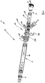
- Figur 1
- schematisiert einen Füllinjektor in einer perspektivischen, teilzerlegten Ansicht;
- Figur 2
- ein Detail nach
Figur 1 zeigend einen Injektorkopf; - Figur 3
- einen perspektivische Ansicht einer Injektorkappe und des sich anschließenden Rohres;
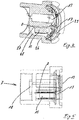
- Figur 4
- eine teilgeschnittene perspektivische Ansicht der Zylinderkappe nach
Figur 3 ; - Figur 5
- eine Schnittansicht der Zylinderkappe nach
Figur 4 mit einem am Kolben anzuordnenden Magnetring; - Ein erfindungsgemäßer Füllinjektor 1 für ein Formwerkzeug besitzt ein Injektorgehäuse 2, welches einen zylinderförmigen Hohlraum 6 aufweist, in welchem eine Schließkolbeneinheit 3 axial beweglich angeordnet und gelagert ist.
- Das Injektorgehäuse 2 besitzt eine Zuführung 4 für Schaumstoffpartikel zum Hohlraum 6.
- An einem zum Formwerkzeug weisenden Ende des zylinderförmigen Hohlraums 6 besitzt der Füllinjektor 1 eine Werkzeugmündung 5 zum Zuführen des Kunststoffmaterials zu einem Formwerkzeug.
- In an sich bekannter Weise ist die Schließkolbeneinheit 3 in einer Schließstellung so weit nach vorne geschoben, dass sie die Werkzeugmündung 5 verschließt und in einer Offenstellung aus dem zylinderförmigen Hohlraum 6 zumindest im Bereich zwischen der Zuführung 4 und der Werkzeugmündung 5 herausgezogen ist.
- Das Injektorgehäuse 2 ist aus einem Injektorrohr 6 und einer Injektorkappe 7 ausgebildet. Die Injektorkappe 7 verschließt das Injektorrohr 6 an dem von der Werkzeugmündung 5 entfernten Ende 9 bzw. dem der Werkzeugmündung 5 axial diametral gegenüberliegenden Ende 9.
- Das Injektorrohr 6 ist hierbei aus einem vorderen, die Werkzeugmündung 5 aufweisenden Injektorrohrabschnitt 6a und aus einem hinteren Injektorrohrabschnitt 6b ausgebildet, welcher die Injektorkappe 7 aufweist.
- Der Injektorrohrabschnitt 6a ist hierbei insbesondere axial deutlich länger ausgebildet als der hintere Injektorrohrabschnitt 6b.
- Zwischen dem vorderen Injektorrohrabschnitt 6a und dem hinteren Injektorrohrabschnitt 6b ist zur Verbindung der beiden Injektorrohrabschnitte 6a, 6b ein Injektorkopf 10 angeordnet. Der Injektorkopf 10 besitzt einen vorderen Injektorkopf 10a und einen hinteren Injektorkopf 10b, wobei der vordere Injektorkopf 10a an dem vorderen Injektorrohrabschnitt 6a und der hintere Injektorkopf 10b an dem hinteren Injektorrohrabschnitt 6b ausgebildet ist.
- Der vordere Injektorkopf 10a und der hintere Injektorkopf 10b sind lösbar miteinander verbindbar, womit auch der vordere Injektorrohrabschnitt 6a und der hintere Injektorrohrabschnitt 6b miteinander lösbar verbindbar sind.
- Der vordere Injektorkopf 10a und/oder der hintere Injektorkopf 10b besitzen je einen Luftanschluss 11, 12.
- Die Injektorkappe 7 besitzt ebenso einen Luftanschluss 13, der so ausgebildet ist, dass Luft durch die Injektorkappe 7 hindurch in den hinteren Injektorrohrabschnitt 6b führbar ist.
- Die Schließkolbeneinheit 3 besitzt einen im hinteren Injektorrohrabschnitt 6b befindlichen Betätigungskolben 14, wobei der Betätigungskolben 14 an einem die Werkzeugmündung 5 verschließenden Ende gegenüberliegend angeordnet ist.
- Vorzugsweise ist die Schließkolbeneinheit 3 insbesondere mit dem Betätigungskolben 14 verlierungssicher an dem hinteren Injektorrohrabschnitt 6b und/oder dem hinteren Injektorkopf 10b gekoppelt bzw. angeordnet.
- Dies bedeutet, dass beim Lösen des hinteren Injektorrohrabschnitts 6b die Schließkolbeneinheit 3 hieran gekoppelt ist, wobei die Kopplung auch lose sein kann. Wesentlich ist, dass die Schließkolbeneinheit, der hintere Injektorrohrabschnitt 6b und die Injektorkappe 7 eine Baueinheit bilden, welche als Einheit einfach ausgetauscht werden können. Insbesondere verfügt diese Baugruppe über eine Identifikationsnummer, die dieser Baueinheit zugeordnet ist, um willkürliche Austauschungen der Einzelelemente zu verhindern.
- Am Injektorgehäuse 2 oder im Injektorgehäuse 2 ist ein Sensor 8 zum Detektieren einer vorbestimmten Detektionsposition der Schließkolbeneinheit 3 und eine Zähleinrichtung zum Zählen der Anzahl der Detektionspositionen der Schließkolbeneinheit 3 angeordnet. Hiermit lässt sich insbesondere ermitteln, in welcher Stellung sich die Schließkolbeneinheit 3 befindet oder wie oft sie sich in der Detektionsposition befunden hat.
- Die Detektionsposition kann sich im Prinzip an beliebiger Stelle am Injektorgehäuse befinden. Beispielsweise kann die Detektionsposition an der Werkzeugmündung am oder im Injektorrohrabschnitt 6a, im vorderen Injektorkopf 10a, im hinteren Injektorkopf 10b, im hinteren Injektorrohrabschnitt 6b oder an der Injektorkappe 7 vorhanden sein. Zu beachten ist hierbei, dass bei der Messung von Endanschlägen, das heißt bei der Messung an der Werkzeugmündung oder an der Injektorkappe Detektionspositionen ermittelt werden, die pro Arbeitshub nur einmal erreicht werden.
- An den anderen Stellen ist die Detektionsposition dann so ausgewählt, dass jeder Hub, d. h. sowohl der Vor- als auch der Rückhub der Vorrichtung gezählt werden. Dies muss beachtet werden.
- Der Sensor 8 kann somit sowohl an der oder in der Werkzeugmündung 5, am oder im Injektorrohrabschnitt 6a, im vorderen Injektorkopf 10a, im hinteren Injektorkopf 10b, im hinteren Injektorrohrabschnitt 6b oder an oder in der Injektorkappe 7 vorhanden sein.
- Der Füllinjektor 1 kann für das Betreiben des Sensors 8 und/oder einer vorhandenen Zählereinrichtung eine Energieversorgung 15 besitzen. Hierdurch wird sichergestellt, dass der Füllinjektor autark bezüglich des Sensors und des Zählens ist.
- Hierbei kann die Energieversorgung eine Batterie 15 und/oder eine elektromagnetische Induktionseinrichtung sein.
- Wird eine elektromagnetische Induktionseinrichtung verwendet, kann diese einen Teil der Bewegungsenergie der Schließkolbeneinheit 3 in elektrische Energie umwandeln, z. B. durch einen Induktor.
- Vorzugsweise sind gegebenenfalls Speicherelemente zum Speichern der beispielsweise durch Induktion erzeugten Energie vorhanden, insbesondere kann hierfür in an sich bekannter Weise ein Kondensator verwendet werden.
- Bei einer vorteilhaften Ausführungsform der Erfindung (
Figur 2 ) sind der vordere Injektorkopf 10a und der hintere Injektorkopf 10b axial ineinander steckbare Rohrabschnitte, wobei an einem der Injektorköpfe eine umlaufende radiale Verriegelungsnut 20 vorhanden ist. - Am jeweils anderen Injektorkopf 10a, 10b ist entsprechend eine korrespondierende Nut 21 vorhanden, welche in vollständig zusammengeschobenen bzw. eingesteckten Zustand der Injektorköpfe 10a, 10b mit der Nut 20 fluchtet. In die Nut 21 ist eine Verriegelungsklammer 22 einsteckbar, welche sowohl die Nuten 21 als auch die Nut 20 durchgreift und somit für eine axiale Verriegelung der Injektorköpfe 10a, 10b aneinander sorgt.
- Vorzugsweise sind an dem Injektorkopf, der in den jeweiligen anderen Injektorkopf eingesteckt wird (dem Injektorkopf, der im Einsteckbereich über den geringeren Durchmesser verfügt) zumindest ein Zentrierungskeil 23 vorhanden, der in eine entsprechende Zentrierungsnut 24 am jeweils anderen Injektorkopf eingreifbar ausgebildet ist, sodass eine radiale Festlegung der beiden Injektorköpfe 10a, 10b aneinander erfolgt.
- Zudem verfügt die Rohrverbindung zwischen den beiden Injektorköpfen 10a, 10b selbstverständlich über Dichtungen, die insbesondere als O-Ring-Dichtungen oder Dilag-Dichtungen und Führungen ausgebildet sind.
- Bei einer vorteilhaften Ausführungsform sind Sensor und Zähleinrichtung an der Injektorkappe 7 ausgebildet (
Figuren 4, 5 ). - Die Injektorkappe 7 ist hierzu im Wesentlichen zylindrisch ausgebildet und besitzt von einer Außenseite 25 her einen zylindrischen Druckluftanschluss 13, wobei der zylindrische Druckluftanschluss 13 nicht koaxial ausgebildet sein muss.
- Zwischen dem Druckluftanschluss 13 und einer radialen Außenwandung 26 ist eine Leiterplatte 27 angeordnet.
- Auf der Leiterplatte sind insbesondere ein RFID-Chip und ein Mikrocontroller angeordnet. Zudem kann auf der Leiterplatte ein Reed-Kontakt oder ein Hall-Sensor, welcher mit dem Magnetring oder anderen geeigneten Gebern interagiert, angeordnet sein, um die Stellung und/oder die Anzahl der Stellungen der Schließkolbeneinheit 3 zu erfassen.
- Vorzugsweise benachbart zur Leiterplatte 27 ist die Energieversorgung, insbesondere die Energieversorgung in Form einer Batterie 15, vorhanden.
- Zudem ist in diesem Bereich die Anzeige 17 vorhanden, wobei die Anzeige 17 insbesondere eine LED oder eine Mehrzahl von LEDs sein kann, die insbesondere zur Darstellung eines bestimmten Zustands der Batterie und/oder der Wartung oder weiterer gewünschter Parameter blinkt und insbesondere mit einer vorgegebenen Farbe blinkt.
- Um den Druckluftanschluss 13 herum kann eine Datenschnittstelle zum Übermitteln des Zählerstands und insbesondere eine Spule oder Antenne 16 vorhanden sein, wobei die Antenne 16, das Fach 28 für die Batterie und der Raum für die Leiterplatte 27 und die LEDs 17 von einem Deckel 29 abgedeckt werden.
- Um den Innenraum sichtbar zu machen, kann der Deckel 29 insbesondere klarsichtig oder teilopak ausgebildet sein.
- Der Deckel 29 ist an der Injektorkappe 7 insbesondere so angeordnet, dass er nur durch eine Beschädigung oder die Beschädigung einer Plombierung oder dergleichen entfernbar ist, sodass Manipulationen des Innenraums sichtbar sind und insbesondere nur Wartungspersonal befugt ist, einen beschädigten Deckel oder eine beschädigte Plombierung zu ersetzen.
- Um Manipulationen an der Leiterplatte 27 auszuschließen, kann die Leiterplatte 27 mit der Injektorkappe 7 einstückig ausgebildet sein und insbesondere in der Injektorkappe 7 vergossen bzw. eingegossen sein.
- Vorteilhafterweise kann, wenn auf einen Energiespeicher in Form einer Batterie verzichtet wird und die Energie über Energy Harvesting zur Verfügung gestellt wird, die Energieerzeugung beispielsweise durch Induktion direkt zur Zählung verwendet werden, sodass eine Induktionsspule, die die Bewegung des Schließkolbens 3 erfasst, gleichzeitig der Sensor 8 ist.
-
- 1
- Füllinjektor
- 2
- Injektorgehäuse
- 3
- Schließkolbeneinheit
- 4
- Zuführung
- 5
- Werkzeugmündung
- 6
- Hohlraum
- 7
- Injektorkappe
- 8
- Sensor
- 9
- Ende
- 10a
- Injektorkopf
- 10b
- Injektorkopf
- 11
- Luftanschluss
- 12
- Luftanschluss
- 13
- Druckluftanschluss
- 14
- Betätigungskolben
- 15
- Energieversorgung
- 16
- Datenschnittstelle
- 17
- Anzeige
- 18
- Magnetelement
- 20
- Verriegelungsnut
- 21
- Nut
- 22
- Verriegelungsklammer
- 23
- Zentrierungskeil
- 24
- Zentrierungsnut
- 25
- Außenseite
- 26
- Außenwandung
- 27
- Leiterplatte
- 28
- Fach
- 29
- Deckel
- 30
- Antriebselement
Claims (15)
- Füllinjektor (1) für ein Formwerkzeug mit einem Injektorgehäuse (2), das einen zylinderförmigen Hohlraum (6) aufweist, in welchem eine Schließkolbeneinheit (3) beweglich gelagert ist, wobei das Injektorgehäuse (2) eine Zuführung (4) für Kunststoffmaterial zum Hohlraum (6) und an einem zum Formwerkzeug weisenden Ende eine Werkzeugmündung (5) zum Zuführen von Kunststoffmaterial zu einem Formwerkzeug aufweist, und
die Schließkolbeneinheit (3) in einer Schließstellung so weit nach vorne geschoben ist, dass sie die Werkzeugmündung (5) verschließt und in einer Offenstellung aus dem zylinderförmigen Hohlraum (6) zumindest im Bereich zwischen der Zuführung (4) und der Werkzeugmündung (5) herausgezogen ist, dadurch gekennzeichnet, dass im oder am Injektorgehäuse (2) ein Sensor (8) zum Detektieren einer vorbestimmten Detektionsposition der Schließkolbeneinheit und eine Zähleinrichtung zum Zählen der Anzahl der Detektionspositionen der Schließkolbeneinheit (3), in welcher sie sich in der vorbestimmten Detektionsposition befindet, vorgesehen ist. - Füllinjektor nach Anspruch 1,
dadurch gekennzeichnet,
dass das Injektorgehäuse (2) aus einem Injektorrohr (6) und einer Injektorkappe (7) ausgebildet ist, die das Injektorrohr (6) an dem von der Werkzeugmündung (5) entfernten Ende (9) abschließt, wobei vorzugsweise das Injektorrohr (6) aus einem vorderen, die Werkzeugmündung (5) aufweisenden Injektorrohrabschnitt (6a) und aus einem hinteren Injektorrohrabschnitt (6b) ausgebildet ist, welche lösbar miteinander gekoppelt sind, und insbesondere zwischen dem vorderen Injektorrohrabschnitt (6a) und dem hinteren Injektorrohrabschnitt (6b) ein Injektorkopf (10) angeordnet ist, wobei ein vorderer Injektorkopf (10a) und ein hinterer Injektorkopf (10b) angeordnet sind, zwischen welchen die lösbare Verbindung ausgebildet ist, wobei der vordere Injektorkopf (10a) oder der hintere Injektorkopf (10b) einen Luftanschluss (11,12) und die Injektorkappe (7) einen weiteren Luftanschluss (13) aufweisen können, und die Schließkolbeneinheit (3) einen im hinteren Injektorrohrabschnitt (6b) befindlichen Betätigungskolben (14) besitzt, um durch entsprechende Zufuhr von Druckluft durch einen der beiden Luftanschlüsse die Schließkolbeneinheit nach vorne oder nach hinten zu bewegen. - Füllinjektor nach Anspruch 2,
dadurch gekennzeichnet,
dass die Schließkolbeneinheit (3) verlierungssicher an den hinteren Injektorrohrabschnitt (6b) gekoppelt ist. - Füllinjektor nach einem der Ansprüche 1 bis 3,
dadurch gekennzeichnet,
dass der Füllinjektor (1) eine Energieversorgung (15) zum Betreiben des Sensors (8) und der Zähleinrichtung aufweist, welche vorzugsweise als Batterie (15) und/oder elektromagnetische Induktionseinrichtung ausgebildet ist, welche einen Teil der Bewegungsenergie der Schließkolbeneinheit (3) in elektrische Energie umwandelt. - Füllinjektor nach einem der Ansprüche 1 bis 4,
dadurch gekennzeichnet,
dass der Füllinjektor (1) eine Datenschnittstelle (16) zum Übermitteln eines Zählerstandes aufweist, wobei die Datenschnittstelle vorzugsweise als Funkschnittstelle zum berührungslosen Übermitteln eines Zählerstandes ausgebildet ist. - Füllinjektor nach einem der Ansprüche 1 bis 5,
dadurch gekennzeichnet,
dass der Füllinjektor eine Anzeigeeinrichtung (17) zum Anzeigen eines oder mehrerer Betriebszustände aufweist, welche bspw. einem vorbestimmten Zählerstand der Zähleinrichtung oder einem vorbestimmten Zustand einer Energieversorgung entsprechen. - Füllinjektor nach einem der Ansprüche 1 bis 6,
dadurch gekennzeichnet,
dass die vorbestimmte Stellung der Schließkolbeneinheit (3) die Offenstellung ist, wobei die Schließkolbeneinheit (3) vorzugsweise maximal zurückgezogen ist. - Füllinjektor nach einem der Ansprüche 1 bis 7,
dadurch gekennzeichnet,
dass an der Schließkolbeneinheit (3) ein Magnetelement (18) vorgesehen ist und der Sensor (8) zum Detektieren der vorbestimmten Stellung ein Magnetsensor ist. - Füllinjektor nach einem der Ansprüche 1 bis 8,
dadurch gekennzeichnet,
dass am Injektorgehäuse (2) ein Kontaktsensor (8) vorgesehen ist, der die vorbestimmte Stellung der Schließkolbeneinheit durch Kontaktieren der Schließkolbeneinheit detektiert. - Füllinjektor nach einem der Ansprüche 1 bis 9,
dadurch gekennzeichnet,
dass die Zählereinrichtung zum Zählen von mehreren Zählerständen ausgebildet ist, wobei zumindest ein Teil der Zählerstände zurücksetzbar sind, und/oder
dass die Zähleinrichtung an eine Identifikationseinrichtung gekoppelt ist, welche einen Identifikationscode enthält. - Füllinjektor nach einem der Ansprüche 1 bis 10,
dadurch gekennzeichnet,
dass der Füllinjektor (1) ein Füllinjektor (1) für ein Formwerkzeug zum Erzeugen von Partikelschaumstoffteilen ist, wobei die Zuführung (4) zum Zuführen von Schaumstoffpartikeln und die Werkzeugmündung (5) zum Zuführen der Schaumstoffpartikel zu einem Formwerkzeug ausgebildet sind. - Verfahren zum Betreiben eines Füllinjektors (1) nach einem der Ansprüche 1 bis 11,
dadurch gekennzeichnet,
dass bei Erreichen einer vorbestimmten Anzahl von Detektionspositionen ein Wartungssignal ausgegeben wird, wobei das Wartungssignal vorzugsweise als Lichtsignal mittels einer im Füllinjektor integrierten Leuchteinheit, wie z.B. einer Leuchtdiode, und/oder mittels eines Funksignals ausgegeben wird. - Verfahren nach Anspruch 12,
dadurch gekennzeichnet,
dass ein Signal des Ladezustandes einer Batterie und/oder der Funktionalität einer im Füllinjektor enthaltenen Elektronik ausgegeben wird. - Verfahren, insbesondere nach Anspruch 12 oder 13, zum Betreiben eines Füllinjektors (1) nach einem der Ansprüche 1 bis 11,
dadurch gekennzeichnet,
dass ein Gesamtzählerstand der Anzahl von Detektionspositionen gezählt wird, der über eine Datenschnittstelle ausgelesen werden kann. - Verfahren nach Anspruch 14,
dadurch gekennzeichnet,
dass als Datenschnittstelle eine Funkschnittstelle verwendet wird.
Applications Claiming Priority (2)
| Application Number | Priority Date | Filing Date | Title |
|---|---|---|---|
| DE202016104222.4U DE202016104222U1 (de) | 2016-08-01 | 2016-08-01 | Kunststoffmaschine |
| PCT/EP2017/069325 WO2018024676A1 (de) | 2016-08-01 | 2017-07-31 | Füllinjektor und verfahren zum betreiben eines füllinjektors |
Publications (2)
| Publication Number | Publication Date |
|---|---|
| EP3490773A1 EP3490773A1 (de) | 2019-06-05 |
| EP3490773B1 true EP3490773B1 (de) | 2021-04-14 |
Family
ID=59501447
Family Applications (1)
| Application Number | Title | Priority Date | Filing Date |
|---|---|---|---|
| EP17746095.3A Active EP3490773B1 (de) | 2016-08-01 | 2017-07-31 | Füllinjektor und verfahren zum betreiben eines füllinjektors |
Country Status (5)
| Country | Link |
|---|---|
| US (1) | US12036708B2 (de) |
| EP (1) | EP3490773B1 (de) |
| CN (1) | CN109562541A (de) |
| DE (1) | DE202016104222U1 (de) |
| WO (1) | WO2018024676A1 (de) |
Families Citing this family (2)
| Publication number | Priority date | Publication date | Assignee | Title |
|---|---|---|---|---|
| CN111906990B (zh) * | 2020-07-30 | 2021-11-26 | 滁州辉煌无纺科技有限公司 | 一种皮雕发泡机注射枪的枪头固定组件 |
| DE102024116352A1 (de) | 2024-06-11 | 2025-12-11 | Pöppelmann Holding GmbH & Co. KG | Verfahren und Vorrichtung zur Herstellung eines zellulären Formkörpers |
Family Cites Families (24)
| Publication number | Priority date | Publication date | Assignee | Title |
|---|---|---|---|---|
| DE7928606U1 (de) | 1979-10-09 | 1980-01-31 | Basf Ag, 6700 Ludwigshafen | Fuellinjektor, insbesondere zum foerdern von vorgeschaeumten, noch blaehfaehigen, kleinteiligen styrolpolymerisaten |
| JPS5898130A (ja) | 1981-12-09 | 1983-06-10 | Hitachi Ltd | 混練装置 |
| DE3151775A1 (de) * | 1981-12-29 | 1983-09-29 | Flewu AG, 9000 St. Gallen | Verfahren und vorrichtung zum herstellen von im wesentlichen trockenen formlingen aus aufgeschaeumtem thermoplastischen kunststoff, z.b. polystrol |
| DE3541258C1 (de) * | 1985-11-22 | 1987-01-15 | Hahn Ortwin | Adaptives Steuerverfahren zum Schaeumen und Sintern von Kunststoff |
| DE3831600C1 (en) | 1988-09-17 | 1989-08-10 | Ph. Kurtz Eisenhammer Kg, 6981 Hasloch, De | Process and apparatus for filling thermoplastic foam particles into the cavity of a mould |
| JPH07266089A (ja) | 1994-03-29 | 1995-10-17 | Toshiba Chem Corp | 粉体材料用打錠機の金型の交換時期判定方法 |
| EP0829131A1 (de) | 1995-05-29 | 1998-03-18 | Siemens Aktiengesellschaft | Verstärker mit minimaler leistungsaufnahme |
| DE19637349A1 (de) * | 1995-09-27 | 1997-04-10 | Volkswagen Ag | Vorrichtung zum Sintern von schäumbarem Kunststoffmaterial |
| DE19747645A1 (de) | 1997-10-29 | 1999-05-06 | Behr Gmbh & Co | Verfahren zum Herstellen eines Schaumstoffkörpers und Schaumstoffkörper |
| DE29919328U1 (de) | 1999-09-16 | 2000-01-13 | Köster, Karl Otto, 74182 Obersulm | Füllinjektor bei Hartschaumstoff-Formteilautomaten |
| JP2001315179A (ja) * | 2000-05-10 | 2001-11-13 | Nissei Plastics Ind Co | 射出成形機の入力装置 |
| DE20308880U1 (de) * | 2003-06-05 | 2003-08-07 | Otto Männer Heißkanalsysteme GmbH & Co. KG, 79353 Bahlingen | Spritzgießform mit einem ein Zählerwerk aufweisenden elektronischen Datenspeicher |
| DE102008016883A1 (de) | 2008-01-12 | 2009-07-16 | Behl Asia Ltd. | Verfahren zum Herstellen eines Formkörpers aus geschäumten Kunststoff und Einrichtung zur Durchführung des Verfahrens |
| CN101554762B (zh) * | 2009-05-06 | 2012-05-09 | 联塑(杭州)机械有限公司 | 发泡塑料射出成型方法及其设备 |
| DE102009024278B4 (de) | 2009-06-05 | 2012-11-29 | Nico Erlenbach | Füllvorrichtung |
| US8883054B2 (en) * | 2009-06-18 | 2014-11-11 | Progressive Components International Corporation | Mold monitoring |
| US9498909B2 (en) * | 2011-11-23 | 2016-11-22 | Synventive Molding Solutions, Inc. | Injection molding flow control apparatus and method |
| US9205587B2 (en) * | 2012-08-08 | 2015-12-08 | Synventive Molding Solutions, Inc. | Flow control apparatus and method |
| EP2671633A1 (de) | 2012-06-06 | 2013-12-11 | Basf Se | Verfahren zum Transport geschäumter thermoplastischer Polymerpartikel |
| US20160214286A1 (en) * | 2013-10-02 | 2016-07-28 | Covestro Deuschland AG | Method for producing a moulded part by structural foam moulding, moulded part of an expanded thermoplastic material and uses therefor |
| DE102013114570B4 (de) | 2013-12-19 | 2019-05-02 | Kurtz Gmbh | Injektor zum Befüllen einer Form mit Kunststoffpartikeln |
| DE102014117332A1 (de) * | 2014-11-26 | 2016-06-02 | Kurtz Gmbh | Verfahren und Vorrichtung zum Herstellen von Partikelschaumstoffteilen |
| US10155399B2 (en) * | 2015-06-29 | 2018-12-18 | Inteva Products, Llc | Product molding system and method of labeling molded products |
| AT517390A1 (de) * | 2015-07-03 | 2017-01-15 | Sonderhoff Engineering Gmbh | Dosiervorrichtung für flüssigen Kunststoff |
-
2016
- 2016-08-01 DE DE202016104222.4U patent/DE202016104222U1/de active Active
-
2017
- 2017-07-31 EP EP17746095.3A patent/EP3490773B1/de active Active
- 2017-07-31 CN CN201780047514.4A patent/CN109562541A/zh active Pending
- 2017-07-31 WO PCT/EP2017/069325 patent/WO2018024676A1/de not_active Ceased
- 2017-07-31 US US16/321,848 patent/US12036708B2/en active Active
Non-Patent Citations (1)
| Title |
|---|
| None * |
Also Published As
| Publication number | Publication date |
|---|---|
| DE202016104222U1 (de) | 2017-11-03 |
| WO2018024676A1 (de) | 2018-02-08 |
| EP3490773A1 (de) | 2019-06-05 |
| US12036708B2 (en) | 2024-07-16 |
| US20190168428A1 (en) | 2019-06-06 |
| CN109562541A (zh) | 2019-04-02 |
Similar Documents
| Publication | Publication Date | Title |
|---|---|---|
| EP2995424B1 (de) | Handzange | |
| DE69009609T2 (de) | Wiederholnietvorrichtung. | |
| DE19917222A1 (de) | Schraube sowie Vorrichtung zur Handhabung einer derartigen Schraube | |
| DE102017124194A1 (de) | Überwachungsgerät für eine spritzgussform | |
| DE102015014585A1 (de) | Sensorisch überwachter Blocksauger | |
| WO2016202355A1 (de) | Drehantrieb mit stellungserfassungseinrichtung und kalibrierungsverfahren | |
| EP3501744B1 (de) | Werkzeug für die montage eines meissels an und/oder die demontage eines meissels von einem meisselhaltersystem einer fräsmaschine | |
| EP0796664A2 (de) | Beschichtungsanlage mit auswechselbarem Behälter | |
| EP3490773A1 (de) | Füllinjektor und verfahren zum betreiben eines füllinjektors | |
| DE102011005860A1 (de) | Vorrichtung und Verfahren zur Prüfung einer Stranggießanlage | |
| DE102014119189A1 (de) | Fügeelementzuführvorrichtung | |
| DE202011106323U1 (de) | Vorrichtung zum Bereithalten von wenigstens einem Werkzeugeinsatz | |
| EP4086400B1 (de) | Kanalinspektions- und/oder wartungssystem | |
| EP0417427B1 (de) | Einrichtung zur Überwachung des Druckes eines Fahrzeugreifens | |
| DE102009011242A1 (de) | Grenzsignalgeber und Verfahren zum Betreiben eines Grenzsignalgebers | |
| EP1624151B1 (de) | Aufnahme für rohrförmiges Bohrwerkzeug | |
| DE10029392B4 (de) | Nietsetzgerät | |
| EP3527760B1 (de) | Rastbolzen | |
| DE19601280C2 (de) | Verfahren zum Spritzgießen von Werkstücken | |
| DE102005060674A1 (de) | Positionssensor in Stabbauweise sowie Verfahren zum Austausch | |
| EP1232812A2 (de) | Nietsetzgerät mit Einrichtung zum Abtransport abgerissener Nietstifte | |
| EP2595736A1 (de) | Misch-, rühr- oder dispergierverfahren und vorrichtung hierfür | |
| DE102011003777A1 (de) | Aufladbare RFID-Sonde und Ladestation zum Aufladen der RFID-Sonde | |
| DE112017000471B4 (de) | Integrierte sensorventilvorrichtung | |
| EP0955163B1 (de) | Einrichtung zur Registerkontrolle |
Legal Events
| Date | Code | Title | Description |
|---|---|---|---|
| STAA | Information on the status of an ep patent application or granted ep patent |
Free format text: STATUS: UNKNOWN |
|
| STAA | Information on the status of an ep patent application or granted ep patent |
Free format text: STATUS: THE INTERNATIONAL PUBLICATION HAS BEEN MADE |
|
| PUAI | Public reference made under article 153(3) epc to a published international application that has entered the european phase |
Free format text: ORIGINAL CODE: 0009012 |
|
| STAA | Information on the status of an ep patent application or granted ep patent |
Free format text: STATUS: REQUEST FOR EXAMINATION WAS MADE |
|
| 17P | Request for examination filed |
Effective date: 20190207 |
|
| AK | Designated contracting states |
Kind code of ref document: A1 Designated state(s): AL AT BE BG CH CY CZ DE DK EE ES FI FR GB GR HR HU IE IS IT LI LT LU LV MC MK MT NL NO PL PT RO RS SE SI SK SM TR |
|
| AX | Request for extension of the european patent |
Extension state: BA ME |
|
| DAV | Request for validation of the european patent (deleted) | ||
| DAX | Request for extension of the european patent (deleted) | ||
| GRAP | Despatch of communication of intention to grant a patent |
Free format text: ORIGINAL CODE: EPIDOSNIGR1 |
|
| STAA | Information on the status of an ep patent application or granted ep patent |
Free format text: STATUS: GRANT OF PATENT IS INTENDED |
|
| INTG | Intention to grant announced |
Effective date: 20201216 |
|
| GRAS | Grant fee paid |
Free format text: ORIGINAL CODE: EPIDOSNIGR3 |
|
| GRAA | (expected) grant |
Free format text: ORIGINAL CODE: 0009210 |
|
| STAA | Information on the status of an ep patent application or granted ep patent |
Free format text: STATUS: THE PATENT HAS BEEN GRANTED |
|
| AK | Designated contracting states |
Kind code of ref document: B1 Designated state(s): AL AT BE BG CH CY CZ DE DK EE ES FI FR GB GR HR HU IE IS IT LI LT LU LV MC MK MT NL NO PL PT RO RS SE SI SK SM TR |
|
| REG | Reference to a national code |
Ref country code: GB Ref legal event code: FG4D Free format text: NOT ENGLISH |
|
| REG | Reference to a national code |
Ref country code: CH Ref legal event code: EP |
|
| REG | Reference to a national code |
Ref country code: DE Ref legal event code: R096 Ref document number: 502017010091 Country of ref document: DE |
|
| REG | Reference to a national code |
Ref country code: IE Ref legal event code: FG4D Free format text: LANGUAGE OF EP DOCUMENT: GERMAN |
|
| REG | Reference to a national code |
Ref country code: AT Ref legal event code: REF Ref document number: 1381931 Country of ref document: AT Kind code of ref document: T Effective date: 20210515 |
|
| REG | Reference to a national code |
Ref country code: LT Ref legal event code: MG9D |
|
| REG | Reference to a national code |
Ref country code: NL Ref legal event code: MP Effective date: 20210414 |
|
| PG25 | Lapsed in a contracting state [announced via postgrant information from national office to epo] |
Ref country code: HR Free format text: LAPSE BECAUSE OF FAILURE TO SUBMIT A TRANSLATION OF THE DESCRIPTION OR TO PAY THE FEE WITHIN THE PRESCRIBED TIME-LIMIT Effective date: 20210414 Ref country code: BG Free format text: LAPSE BECAUSE OF FAILURE TO SUBMIT A TRANSLATION OF THE DESCRIPTION OR TO PAY THE FEE WITHIN THE PRESCRIBED TIME-LIMIT Effective date: 20210714 Ref country code: NL Free format text: LAPSE BECAUSE OF FAILURE TO SUBMIT A TRANSLATION OF THE DESCRIPTION OR TO PAY THE FEE WITHIN THE PRESCRIBED TIME-LIMIT Effective date: 20210414 Ref country code: FI Free format text: LAPSE BECAUSE OF FAILURE TO SUBMIT A TRANSLATION OF THE DESCRIPTION OR TO PAY THE FEE WITHIN THE PRESCRIBED TIME-LIMIT Effective date: 20210414 Ref country code: LT Free format text: LAPSE BECAUSE OF FAILURE TO SUBMIT A TRANSLATION OF THE DESCRIPTION OR TO PAY THE FEE WITHIN THE PRESCRIBED TIME-LIMIT Effective date: 20210414 |
|
| PG25 | Lapsed in a contracting state [announced via postgrant information from national office to epo] |
Ref country code: PL Free format text: LAPSE BECAUSE OF FAILURE TO SUBMIT A TRANSLATION OF THE DESCRIPTION OR TO PAY THE FEE WITHIN THE PRESCRIBED TIME-LIMIT Effective date: 20210414 Ref country code: PT Free format text: LAPSE BECAUSE OF FAILURE TO SUBMIT A TRANSLATION OF THE DESCRIPTION OR TO PAY THE FEE WITHIN THE PRESCRIBED TIME-LIMIT Effective date: 20210816 Ref country code: NO Free format text: LAPSE BECAUSE OF FAILURE TO SUBMIT A TRANSLATION OF THE DESCRIPTION OR TO PAY THE FEE WITHIN THE PRESCRIBED TIME-LIMIT Effective date: 20210714 Ref country code: SE Free format text: LAPSE BECAUSE OF FAILURE TO SUBMIT A TRANSLATION OF THE DESCRIPTION OR TO PAY THE FEE WITHIN THE PRESCRIBED TIME-LIMIT Effective date: 20210414 Ref country code: RS Free format text: LAPSE BECAUSE OF FAILURE TO SUBMIT A TRANSLATION OF THE DESCRIPTION OR TO PAY THE FEE WITHIN THE PRESCRIBED TIME-LIMIT Effective date: 20210414 Ref country code: IS Free format text: LAPSE BECAUSE OF FAILURE TO SUBMIT A TRANSLATION OF THE DESCRIPTION OR TO PAY THE FEE WITHIN THE PRESCRIBED TIME-LIMIT Effective date: 20210814 Ref country code: LV Free format text: LAPSE BECAUSE OF FAILURE TO SUBMIT A TRANSLATION OF THE DESCRIPTION OR TO PAY THE FEE WITHIN THE PRESCRIBED TIME-LIMIT Effective date: 20210414 Ref country code: GR Free format text: LAPSE BECAUSE OF FAILURE TO SUBMIT A TRANSLATION OF THE DESCRIPTION OR TO PAY THE FEE WITHIN THE PRESCRIBED TIME-LIMIT Effective date: 20210715 |
|
| REG | Reference to a national code |
Ref country code: DE Ref legal event code: R097 Ref document number: 502017010091 Country of ref document: DE |
|
| PG25 | Lapsed in a contracting state [announced via postgrant information from national office to epo] |
Ref country code: SK Free format text: LAPSE BECAUSE OF FAILURE TO SUBMIT A TRANSLATION OF THE DESCRIPTION OR TO PAY THE FEE WITHIN THE PRESCRIBED TIME-LIMIT Effective date: 20210414 Ref country code: SM Free format text: LAPSE BECAUSE OF FAILURE TO SUBMIT A TRANSLATION OF THE DESCRIPTION OR TO PAY THE FEE WITHIN THE PRESCRIBED TIME-LIMIT Effective date: 20210414 Ref country code: CZ Free format text: LAPSE BECAUSE OF FAILURE TO SUBMIT A TRANSLATION OF THE DESCRIPTION OR TO PAY THE FEE WITHIN THE PRESCRIBED TIME-LIMIT Effective date: 20210414 Ref country code: EE Free format text: LAPSE BECAUSE OF FAILURE TO SUBMIT A TRANSLATION OF THE DESCRIPTION OR TO PAY THE FEE WITHIN THE PRESCRIBED TIME-LIMIT Effective date: 20210414 Ref country code: DK Free format text: LAPSE BECAUSE OF FAILURE TO SUBMIT A TRANSLATION OF THE DESCRIPTION OR TO PAY THE FEE WITHIN THE PRESCRIBED TIME-LIMIT Effective date: 20210414 Ref country code: RO Free format text: LAPSE BECAUSE OF FAILURE TO SUBMIT A TRANSLATION OF THE DESCRIPTION OR TO PAY THE FEE WITHIN THE PRESCRIBED TIME-LIMIT Effective date: 20210414 Ref country code: ES Free format text: LAPSE BECAUSE OF FAILURE TO SUBMIT A TRANSLATION OF THE DESCRIPTION OR TO PAY THE FEE WITHIN THE PRESCRIBED TIME-LIMIT Effective date: 20210414 |
|
| PLBE | No opposition filed within time limit |
Free format text: ORIGINAL CODE: 0009261 |
|
| STAA | Information on the status of an ep patent application or granted ep patent |
Free format text: STATUS: NO OPPOSITION FILED WITHIN TIME LIMIT |
|
| REG | Reference to a national code |
Ref country code: CH Ref legal event code: PL |
|
| 26N | No opposition filed |
Effective date: 20220117 |
|
| PG25 | Lapsed in a contracting state [announced via postgrant information from national office to epo] |
Ref country code: MC Free format text: LAPSE BECAUSE OF FAILURE TO SUBMIT A TRANSLATION OF THE DESCRIPTION OR TO PAY THE FEE WITHIN THE PRESCRIBED TIME-LIMIT Effective date: 20210414 |
|
| REG | Reference to a national code |
Ref country code: BE Ref legal event code: MM Effective date: 20210731 |
|
| PG25 | Lapsed in a contracting state [announced via postgrant information from national office to epo] |
Ref country code: LI Free format text: LAPSE BECAUSE OF NON-PAYMENT OF DUE FEES Effective date: 20210731 Ref country code: CH Free format text: LAPSE BECAUSE OF NON-PAYMENT OF DUE FEES Effective date: 20210731 |
|
| PG25 | Lapsed in a contracting state [announced via postgrant information from national office to epo] |
Ref country code: IS Free format text: LAPSE BECAUSE OF FAILURE TO SUBMIT A TRANSLATION OF THE DESCRIPTION OR TO PAY THE FEE WITHIN THE PRESCRIBED TIME-LIMIT Effective date: 20210814 Ref country code: LU Free format text: LAPSE BECAUSE OF NON-PAYMENT OF DUE FEES Effective date: 20210731 Ref country code: AL Free format text: LAPSE BECAUSE OF FAILURE TO SUBMIT A TRANSLATION OF THE DESCRIPTION OR TO PAY THE FEE WITHIN THE PRESCRIBED TIME-LIMIT Effective date: 20210414 |
|
| PG25 | Lapsed in a contracting state [announced via postgrant information from national office to epo] |
Ref country code: IT Free format text: LAPSE BECAUSE OF FAILURE TO SUBMIT A TRANSLATION OF THE DESCRIPTION OR TO PAY THE FEE WITHIN THE PRESCRIBED TIME-LIMIT Effective date: 20210414 Ref country code: IE Free format text: LAPSE BECAUSE OF NON-PAYMENT OF DUE FEES Effective date: 20210731 Ref country code: BE Free format text: LAPSE BECAUSE OF NON-PAYMENT OF DUE FEES Effective date: 20210731 |
|
| PG25 | Lapsed in a contracting state [announced via postgrant information from national office to epo] |
Ref country code: CY Free format text: LAPSE BECAUSE OF FAILURE TO SUBMIT A TRANSLATION OF THE DESCRIPTION OR TO PAY THE FEE WITHIN THE PRESCRIBED TIME-LIMIT Effective date: 20210414 |
|
| PG25 | Lapsed in a contracting state [announced via postgrant information from national office to epo] |
Ref country code: HU Free format text: LAPSE BECAUSE OF FAILURE TO SUBMIT A TRANSLATION OF THE DESCRIPTION OR TO PAY THE FEE WITHIN THE PRESCRIBED TIME-LIMIT; INVALID AB INITIO Effective date: 20170731 |
|
| REG | Reference to a national code |
Ref country code: AT Ref legal event code: MM01 Ref document number: 1381931 Country of ref document: AT Kind code of ref document: T Effective date: 20220731 |
|
| PG25 | Lapsed in a contracting state [announced via postgrant information from national office to epo] |
Ref country code: AT Free format text: LAPSE BECAUSE OF NON-PAYMENT OF DUE FEES Effective date: 20220731 |
|
| PG25 | Lapsed in a contracting state [announced via postgrant information from national office to epo] |
Ref country code: MK Free format text: LAPSE BECAUSE OF FAILURE TO SUBMIT A TRANSLATION OF THE DESCRIPTION OR TO PAY THE FEE WITHIN THE PRESCRIBED TIME-LIMIT Effective date: 20210414 |
|
| PG25 | Lapsed in a contracting state [announced via postgrant information from national office to epo] |
Ref country code: MT Free format text: LAPSE BECAUSE OF FAILURE TO SUBMIT A TRANSLATION OF THE DESCRIPTION OR TO PAY THE FEE WITHIN THE PRESCRIBED TIME-LIMIT Effective date: 20210414 |
|
| PGFP | Annual fee paid to national office [announced via postgrant information from national office to epo] |
Ref country code: DE Payment date: 20250721 Year of fee payment: 9 |
|
| PGFP | Annual fee paid to national office [announced via postgrant information from national office to epo] |
Ref country code: GB Payment date: 20250722 Year of fee payment: 9 |
|
| PGFP | Annual fee paid to national office [announced via postgrant information from national office to epo] |
Ref country code: FR Payment date: 20250725 Year of fee payment: 9 |
|
| PG25 | Lapsed in a contracting state [announced via postgrant information from national office to epo] |
Ref country code: TR Free format text: LAPSE BECAUSE OF FAILURE TO SUBMIT A TRANSLATION OF THE DESCRIPTION OR TO PAY THE FEE WITHIN THE PRESCRIBED TIME-LIMIT Effective date: 20210414 |