EP3490625B1 - Vorrichtung mit strukturierter beschichtung zur verwendung als implantat, zur behandlung von trommelfellperforationen - Google Patents
Vorrichtung mit strukturierter beschichtung zur verwendung als implantat, zur behandlung von trommelfellperforationen Download PDFInfo
- Publication number
- EP3490625B1 EP3490625B1 EP17749412.7A EP17749412A EP3490625B1 EP 3490625 B1 EP3490625 B1 EP 3490625B1 EP 17749412 A EP17749412 A EP 17749412A EP 3490625 B1 EP3490625 B1 EP 3490625B1
- Authority
- EP
- European Patent Office
- Prior art keywords
- ssa
- layer
- pdms
- projections
- further layer
- Prior art date
- Legal status (The legal status is an assumption and is not a legal conclusion. Google has not performed a legal analysis and makes no representation as to the accuracy of the status listed.)
- Active
Links
Images







Classifications
-
- A—HUMAN NECESSITIES
- A61—MEDICAL OR VETERINARY SCIENCE; HYGIENE
- A61L—METHODS OR APPARATUS FOR STERILISING MATERIALS OR OBJECTS IN GENERAL; DISINFECTION, STERILISATION OR DEODORISATION OF AIR; CHEMICAL ASPECTS OF BANDAGES, DRESSINGS, ABSORBENT PADS OR SURGICAL ARTICLES; MATERIALS FOR BANDAGES, DRESSINGS, ABSORBENT PADS OR SURGICAL ARTICLES
- A61L27/00—Materials for grafts or prostheses or for coating grafts or prostheses
- A61L27/50—Materials characterised by their function or physical properties, e.g. injectable or lubricating compositions, shape-memory materials, surface modified materials
-
- A—HUMAN NECESSITIES
- A61—MEDICAL OR VETERINARY SCIENCE; HYGIENE
- A61F—FILTERS IMPLANTABLE INTO BLOOD VESSELS; PROSTHESES; DEVICES PROVIDING PATENCY TO, OR PREVENTING COLLAPSING OF, TUBULAR STRUCTURES OF THE BODY, e.g. STENTS; ORTHOPAEDIC, NURSING OR CONTRACEPTIVE DEVICES; FOMENTATION; TREATMENT OR PROTECTION OF EYES OR EARS; BANDAGES, DRESSINGS OR ABSORBENT PADS; FIRST-AID KITS
- A61F2/00—Filters implantable into blood vessels; Prostheses, i.e. artificial substitutes or replacements for parts of the body; Appliances for connecting them with the body; Devices providing patency to, or preventing collapsing of, tubular structures of the body, e.g. stents
- A61F2/0077—Special surfaces of prostheses, e.g. for improving ingrowth
-
- A—HUMAN NECESSITIES
- A61—MEDICAL OR VETERINARY SCIENCE; HYGIENE
- A61F—FILTERS IMPLANTABLE INTO BLOOD VESSELS; PROSTHESES; DEVICES PROVIDING PATENCY TO, OR PREVENTING COLLAPSING OF, TUBULAR STRUCTURES OF THE BODY, e.g. STENTS; ORTHOPAEDIC, NURSING OR CONTRACEPTIVE DEVICES; FOMENTATION; TREATMENT OR PROTECTION OF EYES OR EARS; BANDAGES, DRESSINGS OR ABSORBENT PADS; FIRST-AID KITS
- A61F2/00—Filters implantable into blood vessels; Prostheses, i.e. artificial substitutes or replacements for parts of the body; Appliances for connecting them with the body; Devices providing patency to, or preventing collapsing of, tubular structures of the body, e.g. stents
- A61F2/02—Prostheses implantable into the body
- A61F2/18—Internal ear or nose parts, e.g. ear-drums
-
- A—HUMAN NECESSITIES
- A61—MEDICAL OR VETERINARY SCIENCE; HYGIENE
- A61L—METHODS OR APPARATUS FOR STERILISING MATERIALS OR OBJECTS IN GENERAL; DISINFECTION, STERILISATION OR DEODORISATION OF AIR; CHEMICAL ASPECTS OF BANDAGES, DRESSINGS, ABSORBENT PADS OR SURGICAL ARTICLES; MATERIALS FOR BANDAGES, DRESSINGS, ABSORBENT PADS OR SURGICAL ARTICLES
- A61L27/00—Materials for grafts or prostheses or for coating grafts or prostheses
- A61L27/36—Materials for grafts or prostheses or for coating grafts or prostheses containing ingredients of undetermined constitution or reaction products thereof, e.g. transplant tissue, natural bone, extracellular matrix
- A61L27/3683—Materials for grafts or prostheses or for coating grafts or prostheses containing ingredients of undetermined constitution or reaction products thereof, e.g. transplant tissue, natural bone, extracellular matrix subjected to a specific treatment prior to implantation, e.g. decellularising, demineralising, grinding, cellular disruption/non-collagenous protein removal, anti-calcification, crosslinking, supercritical fluid extraction, enzyme treatment
- A61L27/3691—Materials for grafts or prostheses or for coating grafts or prostheses containing ingredients of undetermined constitution or reaction products thereof, e.g. transplant tissue, natural bone, extracellular matrix subjected to a specific treatment prior to implantation, e.g. decellularising, demineralising, grinding, cellular disruption/non-collagenous protein removal, anti-calcification, crosslinking, supercritical fluid extraction, enzyme treatment characterised by physical conditions of the treatment, e.g. applying a compressive force to the composition, pressure cycles, ultrasonic/sonication or microwave treatment, lyophilisation
-
- A—HUMAN NECESSITIES
- A61—MEDICAL OR VETERINARY SCIENCE; HYGIENE
- A61L—METHODS OR APPARATUS FOR STERILISING MATERIALS OR OBJECTS IN GENERAL; DISINFECTION, STERILISATION OR DEODORISATION OF AIR; CHEMICAL ASPECTS OF BANDAGES, DRESSINGS, ABSORBENT PADS OR SURGICAL ARTICLES; MATERIALS FOR BANDAGES, DRESSINGS, ABSORBENT PADS OR SURGICAL ARTICLES
- A61L27/00—Materials for grafts or prostheses or for coating grafts or prostheses
- A61L27/36—Materials for grafts or prostheses or for coating grafts or prostheses containing ingredients of undetermined constitution or reaction products thereof, e.g. transplant tissue, natural bone, extracellular matrix
- A61L27/38—Materials for grafts or prostheses or for coating grafts or prostheses containing ingredients of undetermined constitution or reaction products thereof, e.g. transplant tissue, natural bone, extracellular matrix containing added animal cells
- A61L27/3895—Materials for grafts or prostheses or for coating grafts or prostheses containing ingredients of undetermined constitution or reaction products thereof, e.g. transplant tissue, natural bone, extracellular matrix containing added animal cells using specific culture conditions, e.g. stimulating differentiation of stem cells, pulsatile flow conditions
-
- A—HUMAN NECESSITIES
- A61—MEDICAL OR VETERINARY SCIENCE; HYGIENE
- A61B—DIAGNOSIS; SURGERY; IDENTIFICATION
- A61B17/00—Surgical instruments, devices or methods
- A61B17/0057—Implements for plugging an opening in the wall of a hollow or tubular organ, e.g. for sealing a vessel puncture or closing a cardiac septal defect
-
- A—HUMAN NECESSITIES
- A61—MEDICAL OR VETERINARY SCIENCE; HYGIENE
- A61F—FILTERS IMPLANTABLE INTO BLOOD VESSELS; PROSTHESES; DEVICES PROVIDING PATENCY TO, OR PREVENTING COLLAPSING OF, TUBULAR STRUCTURES OF THE BODY, e.g. STENTS; ORTHOPAEDIC, NURSING OR CONTRACEPTIVE DEVICES; FOMENTATION; TREATMENT OR PROTECTION OF EYES OR EARS; BANDAGES, DRESSINGS OR ABSORBENT PADS; FIRST-AID KITS
- A61F2/00—Filters implantable into blood vessels; Prostheses, i.e. artificial substitutes or replacements for parts of the body; Appliances for connecting them with the body; Devices providing patency to, or preventing collapsing of, tubular structures of the body, e.g. stents
- A61F2/0077—Special surfaces of prostheses, e.g. for improving ingrowth
- A61F2002/0081—Special surfaces of prostheses, e.g. for improving ingrowth directly machined on the prosthetic surface, e.g. holes, grooves
-
- A—HUMAN NECESSITIES
- A61—MEDICAL OR VETERINARY SCIENCE; HYGIENE
- A61F—FILTERS IMPLANTABLE INTO BLOOD VESSELS; PROSTHESES; DEVICES PROVIDING PATENCY TO, OR PREVENTING COLLAPSING OF, TUBULAR STRUCTURES OF THE BODY, e.g. STENTS; ORTHOPAEDIC, NURSING OR CONTRACEPTIVE DEVICES; FOMENTATION; TREATMENT OR PROTECTION OF EYES OR EARS; BANDAGES, DRESSINGS OR ABSORBENT PADS; FIRST-AID KITS
- A61F2/00—Filters implantable into blood vessels; Prostheses, i.e. artificial substitutes or replacements for parts of the body; Appliances for connecting them with the body; Devices providing patency to, or preventing collapsing of, tubular structures of the body, e.g. stents
- A61F2/02—Prostheses implantable into the body
- A61F2/18—Internal ear or nose parts, e.g. ear-drums
- A61F2002/183—Ear parts
-
- A—HUMAN NECESSITIES
- A61—MEDICAL OR VETERINARY SCIENCE; HYGIENE
- A61F—FILTERS IMPLANTABLE INTO BLOOD VESSELS; PROSTHESES; DEVICES PROVIDING PATENCY TO, OR PREVENTING COLLAPSING OF, TUBULAR STRUCTURES OF THE BODY, e.g. STENTS; ORTHOPAEDIC, NURSING OR CONTRACEPTIVE DEVICES; FOMENTATION; TREATMENT OR PROTECTION OF EYES OR EARS; BANDAGES, DRESSINGS OR ABSORBENT PADS; FIRST-AID KITS
- A61F2210/00—Particular material properties of prostheses classified in groups A61F2/00 - A61F2/26 or A61F2/82 or A61F9/00 or A61F11/00 or subgroups thereof
- A61F2210/0076—Particular material properties of prostheses classified in groups A61F2/00 - A61F2/26 or A61F2/82 or A61F9/00 or A61F11/00 or subgroups thereof multilayered, e.g. laminated structures
-
- A—HUMAN NECESSITIES
- A61—MEDICAL OR VETERINARY SCIENCE; HYGIENE
- A61F—FILTERS IMPLANTABLE INTO BLOOD VESSELS; PROSTHESES; DEVICES PROVIDING PATENCY TO, OR PREVENTING COLLAPSING OF, TUBULAR STRUCTURES OF THE BODY, e.g. STENTS; ORTHOPAEDIC, NURSING OR CONTRACEPTIVE DEVICES; FOMENTATION; TREATMENT OR PROTECTION OF EYES OR EARS; BANDAGES, DRESSINGS OR ABSORBENT PADS; FIRST-AID KITS
- A61F2240/00—Manufacturing or designing of prostheses classified in groups A61F2/00 - A61F2/26 or A61F2/82 or A61F9/00 or A61F11/00 or subgroups thereof
- A61F2240/001—Designing or manufacturing processes
-
- A—HUMAN NECESSITIES
- A61—MEDICAL OR VETERINARY SCIENCE; HYGIENE
- A61L—METHODS OR APPARATUS FOR STERILISING MATERIALS OR OBJECTS IN GENERAL; DISINFECTION, STERILISATION OR DEODORISATION OF AIR; CHEMICAL ASPECTS OF BANDAGES, DRESSINGS, ABSORBENT PADS OR SURGICAL ARTICLES; MATERIALS FOR BANDAGES, DRESSINGS, ABSORBENT PADS OR SURGICAL ARTICLES
- A61L2400/00—Materials characterised by their function or physical properties
- A61L2400/18—Modification of implant surfaces in order to improve biocompatibility, cell growth, fixation of biomolecules, e.g. plasma treatment
-
- A—HUMAN NECESSITIES
- A61—MEDICAL OR VETERINARY SCIENCE; HYGIENE
- A61L—METHODS OR APPARATUS FOR STERILISING MATERIALS OR OBJECTS IN GENERAL; DISINFECTION, STERILISATION OR DEODORISATION OF AIR; CHEMICAL ASPECTS OF BANDAGES, DRESSINGS, ABSORBENT PADS OR SURGICAL ARTICLES; MATERIALS FOR BANDAGES, DRESSINGS, ABSORBENT PADS OR SURGICAL ARTICLES
- A61L2420/00—Materials or methods for coatings medical devices
- A61L2420/02—Methods for coating medical devices
-
- A—HUMAN NECESSITIES
- A61—MEDICAL OR VETERINARY SCIENCE; HYGIENE
- A61L—METHODS OR APPARATUS FOR STERILISING MATERIALS OR OBJECTS IN GENERAL; DISINFECTION, STERILISATION OR DEODORISATION OF AIR; CHEMICAL ASPECTS OF BANDAGES, DRESSINGS, ABSORBENT PADS OR SURGICAL ARTICLES; MATERIALS FOR BANDAGES, DRESSINGS, ABSORBENT PADS OR SURGICAL ARTICLES
- A61L2430/00—Materials or treatment for tissue regeneration
- A61L2430/14—Materials or treatment for tissue regeneration for ear reconstruction or ear implants, e.g. implantable hearing aids
Definitions
- the invention relates to a device with a structured coating, in particular for adhesion to rough surfaces, especially biological surfaces, such as, for example, eardrums.
- Adhesion to rough surfaces is often problematic. In the biological field in particular, many adhesives only have inadequate properties. At the same time, there is also the problem that the surface of the adhesives is only insufficiently compatible with biological processes, such as wound healing.
- US 2014/0329061 A1 discloses structured surfaces with individual projections which are also structured on their end face.
- DE 10 2012 112 965 A1 discloses a reversibly structurable surface, the projections being formed by a shape memory alloy.
- WO 2012/054039 A1 discloses a structured surface in which the wettability is controlled by the structuring.
- WO 2010/108003 A2 describes a surface with single walled nanotubes which support the connection of cells.
- DE 10 2010 026 490 A1 discloses a method for producing structured surfaces via an embossing process.
- WO 2007/096082 A1 discloses a surface with filament-like structures.
- Carlos Mota et al. Biofabrication 2015, 7, 025005 describes the production of a structured membrane as a replacement eardrum.
- WO 2016/146792 A1 describes a structured surface with projections which, within a projection, have regions with different modulus of elasticity, in particular with a curved interface.
- Perforation of the eardrum is a common problem that can lead to hearing loss or recurring infections.
- a common cause of eardrum perforation can be otitis media, trauma, and post-operative complications.
- acute, (smaller) perforations which in most cases close spontaneously, and large or chronic perforations.
- These larger perforations require surgical treatment by means of myringoplasty or tympanoplasty, with a high success rate, but in addition to the surgical risk there is also the risk of residual perforation.
- autologous tissue is transplanted during tympanoplasty, which must also be removed.
- transplanted tissue or polymers can be used as "support platforms", the function of which is then improved with the use of biomolecules can be.
- the polymers that can be used include gelatine, silk fibroin, chitosan, alginates or polyglycerol sebacates.
- the invention is based on the object of specifying a device with a structured coating for use in the treatment of eardrum perforations, which has an adhesion in particular on rough, in particular on biological surfaces and avoids the disadvantages of the prior art.
- a device for use in the treatment of eardrum perforations with a structured coating comprising a carrier layer, with a plurality of projections (pillars) being arranged on this carrier layer, each having at least one stem with one from the surface encompass pioneering end face, characterized in that a further layer is arranged at least on the end face, this layer having a different modulus of elasticity than the respective projection.
- This further layer also forms the surface of the device which is used for adhesion to a surface.
- the device therefore comprises, starting from the carrier layer, at least two regions with different modulus of elasticity, namely at least the projection and the further layer arranged thereon.
- This further layer and the face of one Projections form an interface between two areas with different modulus of elasticity.
- the interfaces can also comprise thin layers of connection aids.
- the modulus of elasticity is preferably constant within a range.
- a projection itself can also have further areas which have a different modulus of elasticity.
- the further layer has a lower modulus of elasticity than the projection on which it is arranged. This structure ensures that the stem of the projection is less elastic than the further layer. The trunk of the column is therefore less prone to agglomeration with or without loading. At the same time, the upper part of the projection is more elastic and can also adapt better to rough and / or soft surfaces.
- the interface between the further layer and the end face is not parallel to the surface of the further layer in relation to the respective projection.
- the end face of a projection is curved. It preferably comprises a maximum within the projection. In particular, this is parabolic or hemispherical in shape. As a result, the interface to the further layer is also shaped accordingly.
- the end face can also have a curvature only towards the edge of the projection, while it runs flat in the center of the projection. With such an arrangement, the thickness of the further layer is not constant above the face. If the end face forms a maximum in the center of the projection and the surface of the further layer is flat, the thickness of the further layer above the projection decreases towards the center of the projection.
- Such a shape of the interface means that materials with different elasticity or flexural rigidity are present in this area and interlock. It was found that such an arrangement increases the adhesive force of such a protrusion and also reduces the tendency to collapse.
- the ratio of the minimum vertical thickness of the further layer above the projection in relation to the height of the projection is less than 3, preferably less than 1, in particular less than 0.5, in particular less than 0.2. This affects changes in the thickness of the further layer, e.g. B. in the case of curved phase interfaces due to the geometry of the projections, particularly strong on the adhesion.
- the optimal ratio can also depend on the ratio of the modulus of elasticity and the geometry of the interface.
- the curvature of the end face is convex in the direction of the further layer, i. the phase interface has a maximum.
- the curvature is preferably a spherical curvature, in particular with a radius up to twice the diameter of the projection, in particular at least the diameter of the projection.
- the projection has a beginning of the separation when it is detached from a surface in the middle of the ledge.
- the projections on the carrier layer are column-like.
- the projections are preferably perpendicular to the carrier layer and have a trunk and an end face, wherein the trunk and the end face can have any cross-section (for example, circular, oval, rectangular, square, diamond-shaped, hexagonal, pentagonal, Etc.).
- the projections are preferably designed in such a way that the vertical projection of the end face on the base area of the projection forms an overlap area with the base area, the overlap area and the projection of the overlap area on the end face spanning a body which lies completely within the projection.
- the overlap area comprises at least 50% of the base area, preferably at least 70% of the base area, particularly preferably the overlap area includes the entire base area.
- the projections are therefore preferably not inclined, but can be.
- the end face is aligned parallel to the base area and to the surface. If the end faces are not aligned parallel to the surface and therefore have different vertical heights, the mean vertical height of the end face is regarded as the vertical height of the projection.
- the stem of the projection based on its mean diameter, has an aspect ratio of height to diameter of from 1 to 100, preferably from 1 to 10, particularly preferably from 2 to 5.
- the aspect ratio is greater than 1, preferably at least 3, in particular at least 7, preferably 3 to 15, particularly preferably 3 to 10.
- the mean diameter is understood to mean the diameter of the circle which has the same area as the corresponding cross section of the projection, averaged over the entire height of the projection.
- the ratio of the height of a projection to the diameter at a certain height over the entire height of the projection is always 1 to 100, preferably 1 to 10, particularly preferably 2 to 5. In one embodiment, this aspect ratio is at at least 3, in particular at least 7, preferably from 3 to 15, particularly preferably from 3 to 10.
- the diameter of the circle which has the same area as the corresponding cross section of the projection at the specific height is understood.
- the projections can have widened end faces, so-called “mushroom” structures. It is also possible that the further layer protrudes beyond the front surface and thus forms a “mushroom” structure.
- the projections do not have any widened end faces.
- the surface of the further layer can itself be structured in order to increase its surface.
- the mean vertical height of the further layer is regarded as the vertical thickness of the further layer.
- the vertical height of all projections is in a range from 1 ⁇ m to 10 mm, preferably 1 ⁇ m to 5 mm, in particular 1 ⁇ m to 2 mm, preferably in a range from 10 ⁇ m to 2 mm.
- the vertical thickness of the further layer above an end face is in a range from 1 ⁇ m to 1 mm, preferably 1 ⁇ m to 500 ⁇ m, in particular 1 ⁇ m to 300 ⁇ m, preferably in a range from 1 ⁇ m to 200 ⁇ m, especially in a range from 10 ⁇ m to 200 ⁇ m, very particularly 5 ⁇ m to 100 ⁇ m.
- the further layer preferably has, based on at least 50% of the projection of the base area of a projection onto the surface of the further layer, a perpendicular thickness in the above area or in one of the preferred areas.
- the smallest thickness of the further layer above a projection is preferably always smaller than the maximum vertical height of the projection.
- the vertical thickness of the carrier layer is in a range from 1 ⁇ m to 2 mm, preferably 1 ⁇ m to 500 ⁇ m, in particular 1 ⁇ m to 300 ⁇ m.
- the surface area of the base area corresponds to a circle with a diameter between 0.1 ⁇ m and 5 mm, preferably 0.1 ⁇ m and 2 mm, particularly preferred between 1 ⁇ m and 500 ⁇ m, particularly preferably between 1 ⁇ m and 100 ⁇ m.
- the base area is a circle with a diameter between 0.3 ⁇ m and 2 mm, preferably 1 ⁇ m and 100 ⁇ m.
- the mean diameter of the trunks is preferably between 0.1 ⁇ m and 5 mm, preferably 0.1 ⁇ m and 2 mm, particularly preferably between 1 ⁇ m and 100 ⁇ m.
- the height and the mean diameter are preferably adapted in accordance with the preferred aspect ratio.
- the surface of the end face of a projection, or the surface of the further layer is at least 1.01 times, preferably at least 1.5 times as large as the area of the base area of a projection. It can be greater by a factor of 1.01 to 20, for example.
- the widened end face is between 5% and 100% larger than the base area, particularly preferably between 10% and 50% of the base area.
- the distance between two projections is less than 2 mm, in particular less than 1 mm, very particularly less than 500 ⁇ m or less than 100 ⁇ m.
- the projections are preferably arranged periodically in a regular manner.
- the projections have a height of 5 to 50 ⁇ m, preferably up to 25 ⁇ m.
- the further layer has a vertical thickness of 3 to 70 ⁇ m above the end faces.
- the mean distance of the columnar Projections are between 5 and 50 ⁇ m.
- the thickness of the carrier layer is between 5 and 100 ⁇ m.
- the diameter is 5 to 40 ⁇ m, depending on the distance between the projections.
- the projections are preferably arranged hexagonally.
- the density of the projections is particularly preferably 10,000 to 1,000,000 projections / cm 2 .
- the total thickness of the device including the further layer, projections and carrier layer is preferably between 50 ⁇ m and 300 ⁇ m.
- the moduli of elasticity of all areas of the projection and the further layer are preferably 50 kPa to 3 GPa.
- the modulus of elasticity of soft areas, i. H. in particular the further layer at 50 kPa to 20 MPa, preferably 100 kPa to 10 MPa.
- the modulus of elasticity of the areas with high modulus of elasticity z. B. the projections and z. B. the carrier layer, at 1 MPa to 3 GPa, preferably 2 MPa to 1 GPa.
- the moduli of elasticity are preferably in the ranges given above for all softer and harder areas.
- the ratio of the modulus of elasticity between the lowest modulus of elasticity and the area with the highest modulus of elasticity is preferably less than 1: 2000, in particular less than 1: 1500, preferably less than 1: 1200, regardless of this at least 1: 1.1, preferably at least 1 : 1.5, especially with at least 1: 2.
- a ratio of up to 1: 1000 can be advantageous.
- the further layer preferably has the lowest modulus of elasticity. The ratio is in particular from 1: 1.1 to 1: 500, preferably from 1: 2 to 1: 500.
- the ratio of the modulus of elasticity of the area of the device with the lowest modulus of elasticity and the area with the highest modulus of elasticity is preferably 1: 2 to 1: 200 (soft to hard), in particular 1: 2 to 1: 100 .
- the ratios given above describe the ratio of the modulus of elasticity of the further layer (soft) and the projections (hard).
- the further layer additionally fills the spaces between the projections.
- the device can be seen as a coating of at least two components, these two components having a structured interface with one another due to the projections now embedded in the coating.
- the upper side of the further layer is preferably shaped in a planar manner, likewise preferably also the lower side of the carrier layer.
- the information on the thickness of the further layer relates to the part of the further layer arranged above the end faces.
- the projections are additionally stabilized. It was surprising to find that such layers also have increased adhesion.
- the enclosed projections are also stabilized by the material surrounding them. As a result, tensile forces parallel to the contact surface of the device do not lead to the projections collapsing, but the adhesive force remains present even with such tensile forces. This is important, for example, if, in addition to adhesion, the device also has tensile forces parallel to the contact surface should endure. For example when applying to wounds to be closed or injuries to eardrums.
- this layer is easy to keep clean or sterile, since no dirt can accumulate in the gaps.
- the filled structure can also reduce stress peaks which occur in the case of free-standing projections when they are detached from a surface.
- such a device can be produced more easily, since the carrier layer with the projections only has to be covered with the material of the further layer. Complex structuring steps are not required.
- the surface of the device appears closed and uniform in this embodiment. This also makes it easier to modify to adapt to applications. Treatment of the surface then has no effect on the structure within the coating.
- the surface can be functionalized or treated with known processes.
- the further layer is part of a film which connects the projections. In this case, the spaces between the projections are not filled.
- the film preferably has a thickness which is less than 100%, preferably less than 50%, particularly preferably less than 30% of the vertical Height of the bridged projections is. The film is not included in the calculation of the height.
- the film preferably has a thickness of less than 2 mm, preferably less than 1 mm, particularly preferably less than 800 ⁇ m.
- the projections can consist of many different materials, elastomers are preferred, and crosslinkable elastomers are particularly preferred.
- the areas with a higher modulus of elasticity can also include thermosetting plastics.
- the projections and the further layer can therefore comprise the following materials: epoxy and / or silicone-based elastomers, polyurethanes, epoxy resins, acrylate systems, methacrylate systems, polyacrylates as homo- and copolymers, polymethacrylates as homo- and copolymers (PMMA, AMMA acrylonitrile / methyl methacrylate), polyurethane (meth) acrylates, silicones, silicone resins, rubber, such as R rubber (NR natural rubber, IR poly-isoprene rubber, BR butadiene rubber, SBR styrene-butadiene rubber, CR chloropropene rubber, NBR nitrile rubber, M rubber (EPM ethene-propene rubber, EPDM ethylene-propylene Rubber), unsaturated polyester resins, formaldehyde resins, vinyl ester resins, polyethylenes as homo- or copolymers, as well as mixtures and copolymers of the aforementioned materials.
- hydrogels for example based on polyurethanes, polyvinylpyrrolidone, polyethylene oxide, poly (2-acrylamido-2-methyl-1-propanesulfonic acid, silicones, polyacrylamides, hydroxylated polymethacrylates or starch.
- Epoxy- and / or silicone-based elastomers polyurethane (meth) acrylates, polyurethanes, silicones, silicone resins (such as UV-curable PDMS), polyurethane (meth) acrylates, rubber (such as EPM, EPDM) are preferred.
- Crosslinkable silicones such as, for example, polymers based on vinyl-terminated silicones are particularly preferred.
- polyurethane (meth) acrylates polyurethanes
- silicones silicone resins (such as UV-curable PDMS), polyurethane (meth ) Acrylates, rubber (such as EPM, EPDM), in particular crosslinkable silicones such as, for example, polymers based on vinyl-terminated silicones, are preferred.
- hydrogels or pressure-sensitive adhesives can also be used for the further layer.
- the surface of the further layer is treated. This can influence the properties of the surface. This can be done by physical treatment such as plasma treatment, preferably with Ar / O 2 plasma.
- Covalent or non-covalent bonds to additives can also be formed on the surface, for example in order to achieve a certain compatibility with the cells.
- Additives to support cell adhesion such as. B. poly-L-lysine, poly-L-ornithine, collagen or fibronectin. Such additives are known from the field of cell culture.
- substances can also be advantageous to store substances in at least part of the device, which substances are then slowly released.
- substances can, for example, be drugs such as antibiotics, or also auxiliary substances to support cell adhesion or cell growth.
- the projections and the carrier layer are made in one piece and consist of the same material.
- the device comprises further layers, which can optionally be removed.
- the surfaces can be protected before use by removable foils.
- Further stabilizing layers can also be arranged on the carrier layer.
- the carrier layer preferably has a smaller thickness than the maximum height of the projections arranged on it.
- the carrier layer if it consists of the same material as the projections, comprises a material with a higher modulus of elasticity, the elasticity of the entire device can also be influenced with the thickness of the carrier layer.
- the device according to the invention is preferably designed for adhesion to soft substrates.
- the device according to the invention is designed in particular for adhesion to biological tissues.
- it can be designed as a film, for example.
- It can also be designed in combination with the devices to be attached.
- This can be, for example, bandages, but also electrodes or other medical devices such as implants, in particular implants that are not intended to be anchored to bones, or soft implants. These can be iris implants, for example.
- the invention therefore also relates to an implant comprising a device according to the invention, for example on at least part of the surface of the implant.
- the device Due to the adhesion of the device, the device adheres very well to the surface of the eardrum and even allows it to be applied under tension. Due to its structure, it also adheres to the surrounding tissues and not just to the eardrum. If necessary, the device embodied in this way can have different areas with different adhesion include. This can be done, for example, via the material, the layer thickness of the further layer, but also simply through the distribution of the projections within the device.
- the device advantageously designed as a film, therefore comprises at least the carrier layer with the projections, and the further layer is applied to these projections in such a way that the spaces are filled. Because it is designed as a film, the device can be easily cut to the desired size. This can even be done by the treating person, e.g. B. the doctor itself.
- the device Due to its internal structure, the device adheres well to the tissue to which it is applied. In addition to the eardrum, this can also be the surrounding tissue. There is no need for a liquid component to apply the device, which can flow into the ear.
- the device can also be transparent, so that the condition of the tissue underneath the device can be examined without detaching, for example in order to determine the healing.
- the device is preferably transparent.
- the device Due to the dry adhesion, the device can easily be removed again.
- the device can be adapted to the cells to be cultivated via the modulus of elasticity of the two layers, in particular the additional layer on which the cells are cultivated (modulus of elasticity (brain cells): approx. 0.1-1 kPa; Module (muscle cells): approx. 8-17 kPa; E-module (bone cells): approx. 25-40 kPa).
- the device can be divided in a simple manner, in particular after the cells have been cultivated, so that different examinations can be carried out starting from the same cell culture. Since the device can be transparent, the cultures obtained in this way are also suitable for microscopic examinations. They can be cut with a razor blade or scalpel, for example.
- the device can also be used to cultivate the cells on conventional glass carriers, e.g. B. round glasses are applied. Alternatively, the device can also be used directly for cultivation in appropriate cultivation containers.
- the surface of the device can also be treated physically or chemically for cultivation.
- This can be, for example, autoclaving, for example by steam sterilization at 50 to 200 ° C., in particular 100 to 150 ° C., at a pressure of 1 to 5 bar for 5 minutes to 3 hours. With such an autoclaving (121 ° C, 2 bar, 20 minutes) no significant change in the adhesive tension could be observed.
- the surface can be treated with poly-L-lysine, poly-L-ornithine, collagen, fibronectin, gelatine, laminine, keratin, tenascin or perlecan.
- Such additives are known from the field of cell culture.
- the invention also relates to a method for producing an embodiment of the device according to the invention.
- a template is provided for molding the plurality of projections.
- the material for the projections is introduced into this template, preferably as a liquid. If appropriate, the material can also already be at least partially cured.
- the material for the carrier layer i. the surface on which the projections are arranged is applied to the template and cured.
- This is particularly preferably the same material as for the trunks of the projections, so the carrier layer and the trunks are also produced in one step, for example by introducing a larger amount of material directly.
- the carrier layer and the projections are released from the template.
- the material for the further layer is then applied in large quantities to the surface with the projections so that the projections are completely covered. This can be done, for example, by knife coating or spin coating.
- the further layer is hardened.
- range information always includes all - not mentioned - intermediate values and all conceivable sub-intervals.
- SSA Soft Skin Adhesive
- Figure 1 shows a schematic representation of a cross section of an embodiment of the invention.
- the device comprises a carrier layer (100) on which a multiplicity of projections (110) are arranged.
- a further layer (120) is arranged on the end face (140) of the respective projection. This layer also fills the spaces (130) between the projections.
- the surface (150) of the further layer is the surface which is used for the adhesion.
- the projections themselves are preferably circular in cross section and therefore represent pillars.
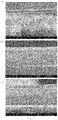
- Figure 2 shows SEM images (SEM: scanning electron microscope), which show the influence of the increasing centrifugal acceleration during the production of the SSA layer on a microstructured PDMS surface. The decrease in layer thickness with increasing speed is clearly visible.
- Figure 3 shows the layer thickness determined with the aid of SEM at different speeds (each for 90 s).
- Layer thickness is the thickness of the layer above the microstructured PDMS surface.
- Figure 4 shows the influence of the weights on the layer thickness of the PDMS carrier layer produced (see also Figure 19 procedure above). By weighing down the layer, thinner layers can be obtained. This results in more flexible devices.
- Figure 5 shows an SEM image of a layer of SSA 50:50 on glass. There, too, the layer thickness can be adjusted by means of the conditions for spin coating. The corresponding layer thicknesses obtained are in Figure 6 shown. The time was always 90 s. However, similar layers can also be obtained at a lower speed and for a longer duration.
- Figure 7 shows the measured values of a measurement Figure 18 in different applications.
- PDMS Slygard 184
- the ratio indicates the proportions of PDMS and crosslinker.
- Figure 8 shows the influence of surface modification on the adhesion of L929 cells (fibroblasts, species mouse). For this purpose, such cells were examined microscopically on the respective surfaces after a plating time of 4 hours. In PDMS and SSA 50:50, minimal cell adhesion was evident if the surfaces were not modified (A and B). Adsorption of poly-L-lysine on the surface led to a significant increase in the adhesive behavior and the formation of cellular processes for PDMS (C) and SSA 50:50 (D).
- Poly-L-ornithine and poly-L-lysine solutions were incubated for 20 minutes at 37 ° C. on the polymer surface; then rinsed with phosphate buffer (PBS).
- PBS phosphate buffer
- Bovine fibronectin was incubated for 60 min at 37 ° C. The concentration was 10 pg / ml PBS. It was then washed with PBS and air-dried.
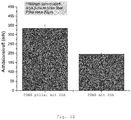
- Microstructured surfaces coated with SSA 50:50 affect the adhesive force.
- SSA 50:50 was applied to a microstructured PDMS layer with pillar heights of 20 ⁇ m by means of spin coating.
- the adhesive force in the overlaid pillar structures is significantly higher than in areas where there are no protrusions. The measurement was carried out on the same sample, which had structured and unstructured areas.
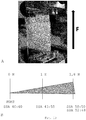
- Figure 13 shows the setup for tensile tests with non-structured two-layer composites against Vitro-Skin®.
- a two-layer composite consisting of a PDMS layer to which SSA was applied in a mixing ratio of 40:60 to 52:48 was produced.
- a preparation made from PDMS served as a reference.
- Figure 13 A shows an example of the setup of the experiment.
- PDMS and SSA in a mixing ratio of 40:60 did not show any adhesion. Maximum adhesion could be achieved with SSA in the mixing ratios 50:50 and 52:48 ( Figure 13 B ).
- L929 cells were plated on PDMS (A) and SSA 50:50 (B) for 48h.
- the mean layer thickness was between 130 ⁇ m and 200 ⁇ m and was determined using an optical system.
- the surface of the polymers was functionalized by applying 0.01% poly-L-lysine (PLL) (PDMS (C) and SSA 50:50 (D)).
- the cells were plated out as single cells.
- PLL poly-L-lysine
- the cells form extensions on both materials (arrows in all figures).
- the cells on SSA appear flattened and elongated.
- the same impression can be obtained on the PLL coated surfaces (C, D).
- all samples were shaken with the same force for a period of about 60s. This leads to a significant detachment of the cells from the PDMS surface (A1).
- the cellular adhesion can still be improved significantly by a surface modification, as shown in D1.
- SSA 50:50 PDMS composite structures were fabricated and applied to the intact tympanic membrane of a dead mouse.
- the composite structure was cut to the required dimensions and then applied with the adhesive side to the intact eardrum. Repeated detachment and repositioning did not result in a rupture of the eardrum. In a further step, part of the eardrum was cut open to simulate a rupture.
- the composite structure could be attached to the edges of the wound and lateral traction applied.
- the complex module of SSA 40:60 and SSA 50:50 was determined by means of rheometry with frequencies between 0.1 and 100 Hz ( Figure 16 ). The measurement amplitude was 0.1%. The results show that SSA 50:50 has a lower modulus of elasticity than SSA 40:60. For PDMS 10: 1 and SSA 40:60 there is approximately a ratio of about 6 and between PDMS 10: 1 and SSA 50:50 a ratio of about 65.
- the maximum elongation of SSA 50:50 is much greater for SSA 50:50 than for PDMS (C).
- the adhesion energy of PDMS is significantly lower when using a rough substrate than the adhesion energy of SSA 40:60 and SSA 50:50 (D).
- the structured coatings according to the invention are more suitable for rough surfaces, ie surfaces which have a roughness of more than 0.2 ⁇ m.
- a roughness of approximately R a 1 ⁇ m was measured for a mouse eardrum after vapor deposition of a thin gold film.
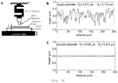
- FIG. A shows a schematic representation of the measuring apparatus for determining the measured values.
- the structured coating (polymer film) is pressed against a substrate (glass substrate) by a movable table (pivotable table).
- a load cell on the substrate can be used to measure the pressing force and also the adhesive force when the structured coating is moved away.
- B shows the measurement of the roughness of the glass substrates used for the measurements (roughness always measured with white light interferometry).
- Figure 19 shows the manufacturing process.
- a structured surface is first produced, which is then further processed in (2) to form a structured coating with a further layer.
- (1) shows from left to right the application of the first polymer (prepolymer 1) to either a glass slide or a microstructured MD40 shape (hexagonally arranged columnar projections with 7 ⁇ m diameter, 18 ⁇ m height, distance from center to center 14 ⁇ m), which is on a glass slide.
- New PDMS is applied to the MD40 mold, air is extracted in a vacuum and a plasma-activated glass slide is applied to the surface.
- Weights are applied to this (e.g.
- the thickness of the PDMS layer which is the carrier layer for the protrusions, can be influenced (e.g. 40 +/- 9 ⁇ m) .
- the MD40 mold can be removed.
- the second polymer e.g. SSA
- the composite structure now produced is polymerized at 95 ° C to 100 ° C.
- the surface can then be functionalized for biological applications. With this method, both structured coatings and unstructured coatings were produced as comparison samples.
- the parameter t indicates the thickness of the further layer above the projections, while b indicates the thickness of the carrier layer.
- Figure 20 shows a cross section for further embodiments of the invention.
- the projections do not have to be rectangular in shape in longitudinal section. It is also possible that the end faces of the projections are curved, in particular convex towards the further layer ( Figure 20 above).
- FIG. 20 Another embodiment of the invention shows Figure 20 below.
- the interface between the projections and the further layer forms a wavy line.
- the projections are therefore three-dimensionally shaped as a paraboloid of revolution.
Landscapes
- Health & Medical Sciences (AREA)
- Life Sciences & Earth Sciences (AREA)
- Oral & Maxillofacial Surgery (AREA)
- Veterinary Medicine (AREA)
- Public Health (AREA)
- General Health & Medical Sciences (AREA)
- Animal Behavior & Ethology (AREA)
- Transplantation (AREA)
- Engineering & Computer Science (AREA)
- Biomedical Technology (AREA)
- Chemical & Material Sciences (AREA)
- Epidemiology (AREA)
- Dermatology (AREA)
- Medicinal Chemistry (AREA)
- Cardiology (AREA)
- Vascular Medicine (AREA)
- Heart & Thoracic Surgery (AREA)
- Pulmonology (AREA)
- Botany (AREA)
- Otolaryngology (AREA)
- Chemical Kinetics & Catalysis (AREA)
- Molecular Biology (AREA)
- Developmental Biology & Embryology (AREA)
- Cell Biology (AREA)
- Zoology (AREA)
- Materials For Medical Uses (AREA)
- Prostheses (AREA)
- Apparatus Associated With Microorganisms And Enzymes (AREA)
- Micro-Organisms Or Cultivation Processes Thereof (AREA)
Description
- Die Erfindung betrifft eine Vorrichtung mit einer strukturierten Beschichtung, insbesondere zur Adhäsion auf rauen Oberflächen, vor allem biologischen Oberflächen, wie beispielsweise Trommelfellen.
- Die Adhäsion auf rauen Oberflächen ist häufig problematisch. Insbesondere im biologischen Bereich zeigen viele Klebstoffe nur unzureichende Eigenschaften. Gleichzeitig besteht auch das Problem, dass die Oberfläche der Klebstoffe nur unzureichend kompatibel mit biologischen Prozessen, wie beispielsweise Wundheilung ist.
- Eine Alternative bieten da trockenadhäsive Oberflächen, wie beispielswiese Geckostrukturen, welche ohne die Vermittlung durch Klebstoffe eine Adhäsion auch an rauen Oberflächen zeigen können. Allerdings sind diese sehr häufig herzustellen und nur beschränkt anpassbar.
-
DE 10 2014 119 470 A1 offenbart strukturierte Oberflächen mit schaltbarer Adhäsion, wobei die Oberflächen Vorsprünge mit unterschiedlicher senkrechter Höhe aufweisen. -
US 2014/0329061 A1 offenbart strukturierte Oberflächen mit einzelnen Vorsprüngen, welche auf ihrer Stirnfläche ebenfalls strukturiert sind. -
DE 10 2012 112 965 A1 offenbart eine reversibel strukturierbare Oberfläche, wobei die Vorsprünge durch eine Formgedächtnislegierung gebildet werden. -
WO 2012/054039 A1 offenbart eine strukturierte Oberfläche, bei der durch die Strukturierung die Benetzbarkeit gesteuert wird. -
WO 2010/108003 A2 beschreibt eine Oberfläche mit single walled nanotubes, welche die Anbindung von Zellen unterstützen. -
DE 10 2010 026 490 A1 offenbart ein Verfahren zur Herstellung von strukturierten Oberflächen über ein Prägeverfahren. -
WO 2007/096082 A1 offenbart eine Oberfläche mit filamentartigen Strukturen. - Carlos Mota et al. Biofabrication 2015, 7, 025005 beschreibt die Herstellung einer strukturierten Membran als Trommelfellersatz.
-
WO 2016/146792 A1 beschreibt eine strukturierte Oberfläche mit Vorsprüngen, welche innerhalb eines Vorsprungs Bereiche mit unterschiedlichem Elastizitätsmodul aufweisen, insbesondere mit gekrümmter Grenzfläche. - Trommelfellperforationen sind ein häufig auftretendes Problem, welche zum Hörverlust oder häufig wiederauftretenden Infektionen führen können. Eine häufige Ursache für Trommelfellperforationen können Mittelohrentzündungen, Traumata und postoperative Komplikationen sein. Grundsätzlich kann zwischen akuten, (kleineren) Perforationen, die sich in den meisten Fällen spontan verschließen, und großen oder chronischen Perforationen unterschieden werden. Diese größeren Perforationen benötigen eine operative Versorgung mittels Myringoplastie oder Tympanoplastie, wobei eine hohe Erfolgsquote auftritt, aber neben dem Operationsrisiko auch die Gefahr einer Restperforation besteht. Des Weiteren wird bei der Tympanoplastie autologes Gewebe transplantiert, welches zusätzlich entnommen werden muss. Eines der Hauptprobleme bei der Regeneration von Trommelfellverletzungen stellt eine fehlende Trägerschicht für die Migration von Epithelzellen und die Ausbildung einer trilammelaren Membran dar. Als "Supportplattformen" können generell entweder transplantierte Gewebe, oder Polymere verwendet werden, deren Funktion dann noch mit der Verwendung von Biomolekülen verbessert werden kann. Zu den verwendbaren Polymeren zählen unter anderem Gelatine, Seidenfibroin, Chitosan, Alginate oder Polyglycerolsebacate. Eine aktuelle Übersicht über Ergebnisse bei der Verwendung dieser Polymere und verschiedener Wachstumsfaktoren findet sich in der Übersichtsarbeit von Hong et al. Auch wenn viele der verwendeten Polymere zu hervorragenden Ergebnissen bzgl. des Perforationsverschlusses führen, bestehen bedeutende Unterschiede in der Morphologie des Gewebes.
- Der Erfindung liegt die Aufgabe zugrunde eine Vorrichtung mit einer strukturierten Beschichtung zur Verwendung bei der Behandlung von Trommelfellperforationen anzugeben, welche eine Adhäsion insbesondere auf rauen, insbesondere auf biologischen Oberflächen aufweist und die Nachteile des Stands der Technik vermeidet.
- Diese Aufgabe wird durch die Erfindungen mit den Merkmalen der unabhängigen Ansprüche gelöst. Vorteilhafte Weiterbildungen der Erfindungen sind in den Unteransprüchen gekennzeichnet. Der Wortlaut sämtlicher Ansprüche wird hiermit durch Bezugnahme zum Inhalt dieser Beschreibung gemacht. Die Erfindungen umfassen auch alle sinnvollen und insbesondere alle erwähnten Kombinationen von unabhängigen und/oder abhängigen Ansprüchen.
- Die Aufgabe wird gelöst durch eine Vorrichtung zur Verwendung bei der Behandlung von Trommelfellperforationen mit einer strukturierten Beschichtung, wobei die Vorrichtung eine Trägerschicht umfasst, wobei auf dieser Trägerschicht eine Vielzahl von Vorsprüngen (Pillars) angeordnet ist, die mindestens jeweils einen Stamm mit einer von der Oberfläche wegweisenden Stirnfläche umfassen, dadurch gekennzeichnet, dass mindestens auf der Stirnfläche eine weitere Schicht angeordnet ist, wobei diese Schicht einen anderen Elastizitätsmodul aufweist als der jeweilige Vorsprung.
- Diese weitere Schicht bildet auch die Oberfläche der Vorrichtung, welche zur Adhäsion an einer Oberfläche verwendet wird.
- In senkrechter Richtung umfasst die Vorrichtung an der Position eines Vorsprungs daher ausgehend von der Trägerschicht mindestens zwei Bereiche mit unterschiedlichem Elastizitätsmodul, nämlich mindestens den Vorsprung und die darauf angeordnete weitere Schicht. Diese weitere Schicht und die Stirnfläche eines Vorsprungs bilden eine Grenzfläche zwischen zwei Bereichen mit unterschiedlichem Elastizitätsmodul. Abhängig von dem Herstellungsverfahren können die Grenzflächen auch dünne Schichten von Verbindungshilfsmitteln umfassen.
- Innerhalb eines Bereichs ist der Elastizitätsmodul bevorzugt konstant.
- Ein Vorsprung selbst kann auch noch weitere Bereiche aufweisen, welche einen unterschiedlichen Elastizitätsmodul aufweisen.
- Die weitere Schicht weist einen geringeren Elastizitätsmodul auf, als der Vorsprung, auf dem sie angeordnet ist. Durch diesen Aufbau wird erreicht, dass der Stamm des Vorsprungs weniger elastisch ist als die weitere Schicht. Der Stamm der Säule neigt daher weniger zur Agglomeration mit oder ohne Belastung. Gleichzeitig ist der obere Teil des Vorsprungs elastischer und kann sich besser auch an raue und/oder weiche Oberflächen anpassen.
- In einer weiteren Ausführungsform der Erfindung ist die Grenzfläche zwischen weiterer Schicht und Stirnfläche nicht parallel zur Oberfläche der weiteren Schicht bezogen auf den jeweiligen Vorsprung.
- In einer Ausführungsform der Erfindung ist die Stirnfläche eines Vorsprungs gekrümmt. Bevorzugt umfasst sie ein Maximum innerhalb des Vorsprungs. Insbesondere ist diese parabolisch oder halbkugelförmig geformt. Dadurch ist auch die Grenzfläche zur weiteren Schicht entsprechend geformt. Die Stirnfläche kann dabei auch nur zum Rand des Vorsprungs hin eine Krümmung aufweisen, während sie in der Mitte des Vorsprungs eben verläuft. Bei einer solchen Anordnung ist die Dicke der weiteren Schicht oberhalb der Stirnfläche nicht konstant. Bildet die Stirnfläche ein Maximum in der Mitte des Vorsprungs und die Oberfläche der weiteren Schicht ist plan geformt, so nimmt die Dicke der weiteren Schicht oberhalb des Vorsprungs zur Mitte des Vorsprungs hin ab.
- Eine solche Form der Grenzfläche führt dazu, dass in diesem Bereich Materialien mit unterschiedlicher Elastizität oder Biegesteifigkeit vorliegen und ineinandergreifen. Es zeigte sich, dass eine solche Anordnung die Adhäsionskraft eines solchen Vorsprungs erhöht und auch die Neigung zum Kollabieren verringert.
- In einer Ausführungsform der Erfindung beträgt das Verhältnis der minimalen senkrechte Dicke der weiteren Schicht oberhalb des Vorsprungs im Verhältnis zur Höhe des Vorsprungs weniger als 3, bevorzugt weniger als 1, insbesondere weniger als 0,5, insbesondere weniger als 0,2. Dadurch wirken sich Veränderungen der Dicke der weiteren Schicht, z. B. bei gekrümmten Phasengrenzflächen durch die Geometrie der Vorsprünge, besonders stark auf die Adhäsion aus. Das optimale Verhältnis kann auch vom Verhältnis der Elastizitätsmodule, sowie der Geometrie der Grenzfläche abhängen.
- In einer Ausführungsform der Erfindung ist die Krümmung der Stirnfläche konvex in Richtung der weiteren Schicht, d.h. die Phasengrenzfläche weist ein Maximum auf. Bevorzugt ist die Krümmung eine kugelförmige Krümmung, insbesondere mit einem Radius bis zu dem doppelten Durchmesser des Vorsprungs, insbesondere mindestens dem Durchmesser des Vorsprungs.
- In einer weiteren Ausführungsform der Erfindung weist der Vorsprung bei Ablösung von einer Oberfläche einen Beginn der Ablösung in der Mitte des Vorsprungs auf. Die vorteilhaften Parameter für Elastizitätsmodul, Größenverhältnis und Geometrie der Grenzfläche, insbesondere konvexe Grenzfläche, können durch Simulationen und Messungen bestimmt werden.
- In einer bevorzugten Ausführungsform der Erfindung sind die Vorsprünge auf der Trägerschicht säulenartig ausgebildet. Dies bedeutet, dass es sich um bevorzugt senkrecht zur Trägerschicht ausgebildete Vorsprünge handelt, welche einen Stamm und eine Stirnfläche aufweisen, wobei der Stamm und die Stirnfläche einen beliebigen Querschnitt aufweisen können (beispielsweise kreisförmig, oval, rechteckig, quadratisch, rautenförmig, sechseckig, fünfeckig, etc.).
- Bevorzugt sind die Vorsprünge so ausgebildet, dass die senkrechte Projektion der Stirnfläche auf die Grundfläche des Vorsprungs mit der Grundfläche eine Überlappungsfläche bildet, wobei die Überlappungsfläche und die Projektion der Überlappungsfläche auf die Stirnfläche einen Körper aufspannt, welcher vollständig innerhalb des Vorsprungs liegt. In einer bevorzugten Ausführungsform der Erfindung umfasst die Überlappungsfläche mindestens 50 % der Grundfläche, bevorzugt mindestens 70 % der Grundfläche, besonders bevorzugt umfasst die Überlappungsfläche die gesamte Grundfläche. Die Vorsprünge sind daher bevorzugt nicht geneigt, können es aber sein.
- In einer bevorzugten Ausführungsform ist die Stirnfläche parallel zur Grundfläche und zur Oberfläche ausgerichtet. Falls die Stirnflächen nicht parallel zur Oberfläche ausgerichtet sind und daher verschiedene senkrechte Höhen aufweisen, wird als senkrechte Höhe des Vorsprungs die mittlere senkrechte Höhe der Stirnfläche angesehen.
- In einer bevorzugten Ausführungsform der Erfindung weist der Stamm des Vorsprungs bezogen auf seinen mittleren Durchmesser ein Aspektverhältnis von Höhe zu Durchmesser von 1 bis 100, bevorzugt von 1 bis 10, besonders bevorzugt von 2 bis 5 auf.
- In einer Ausführungsform liegt das Aspektverhältnis bei größer 1, bevorzugt bei mindestens 3, insbesondere bei mindestens 7, bevorzugt bei 3 bis 15, besonders bevorzugt bei 3 bis 10.
- Unter dem mittleren Durchmesser wird dabei der Durchmesser des Kreises verstanden, der die gleiche Fläche wie der entsprechende Querschnitt des Vorsprungs aufweist, gemittelt über die gesamte Höhe des Vorsprungs.
- In einer weiteren Ausführungsform der Erfindung liegt das Verhältnis der Höhe eines Vorsprungs zum Durchmesser bei einer bestimmten Höhe über die gesamte Höhe des Vorsprungs immer bei 1 bis 100, bevorzugt bei 1 bis 10, besonders bevorzugt bei 2 bis 5. In einer Ausführungsform liegt dieses Aspektverhältnis bei mindestens 3, insbesondere bei mindestens 7, bevorzugt bei 3 bis 15, besonders bevorzugt bei 3 bis 10. Dabei wird unter Durchmesser der Durchmesser des Kreises verstanden, der die gleiche Fläche wie der entsprechende Querschnitt des Vorsprungs bei der bestimmten Höhe aufweist.
- Die Vorsprünge können verbreiterte Stirnflächen aufweisen, sogenannte "mushroom"-Strukturen. Es ist auch möglich, dass die weitere Schicht über die Stirnfläche hinausragt und so eine "mushroom"-Struktur bildet.
- In einer bevorzugten Ausführungsform weisen die Vorsprünge keine verbreiterten Stirnflächen auf.
- Die Oberfläche der weiteren Schicht kann selbst strukturiert sein, um ihre Oberfläche zu erhöhen. In diesem Fall wird als senkrechte Dicke der weiteren Schicht die mittlere senkrechte Höhe der weiteren Schicht angesehen.
- In einer bevorzugten Ausführungsform liegt die senkrechte Höhe aller Vorsprünge in einem Bereich von 1 µm bis 10 mm, bevorzugt 1 µm bis 5 mm, insbesondere 1 µm bis 2 mm, bevorzugt in einem Bereich von 10 µm bis 2 mm.
- In einer bevorzugten Ausführungsform liegt die senkrechte Dicke der weiteren Schicht oberhalb einer Stirnfläche in einem Bereich von 1 µm bis 1 mm, bevorzugt 1 µm bis 500 µm, insbesondere 1 µm bis 300 µm, bevorzugt in einem Bereich von 1 µm bis 200 µm, insbesondere in einem Bereich von 10 µm bis 200 µm, ganz besonders 5 µm bis 100 µm.
- Bevorzugt weist die weitere Schicht bezogen auf mind. 50 % der Projektion der Grundfläche eines Vorsprungs auf die Oberfläche der weiteren Schicht eine senkrechte Dicke in dem vorstehenden Bereich oder einem der bevorzugten Bereiche auf.
- Die kleinste Dicke der weiteren Schicht oberhalb eines Vorsprungs ist bevorzugt immer kleiner als die maximale senkrechte Höhe des Vorsprungs.
- In einer bevorzugten Ausführungsform liegt die senkrechte Dicke der Trägerschicht in einem Bereich von 1 µm bis 2 mm, bevorzugt 1 µm bis 500 µm, insbesondere 1 µm bis 300 µm.
- In einer bevorzugten Ausführungsform entspricht die Grundfläche von der Fläche her einem Kreis mit einem Durchmesser zwischen 0,1 µm bis 5 mm, bevorzugt 0,1 µm und 2 mm, insbesondere bevorzugt zwischen 1 µm und 500 µm, besonders bevorzugt zwischen 1 µm und 100 µm. In einer Ausführungsform ist die Grundfläche ein Kreis mit einem Durchmesser zwischen 0,3 µm und 2 mm, bevorzugt 1 µm und 100 µm.
- Der mittlere Durchmesser der Stämme liegt bevorzugt zwischen 0,1 µm bis 5 mm, bevorzugt 0,1 µm und 2 mm, insbesondere bevorzugt zwischen 1 µm und 100 µm. Bevorzugt ist die Höhe und der mittlere Durchmesser entsprechend dem bevorzugten Aspektverhältnis angepasst.
- In einer bevorzugten Ausführungsform ist bei verbreiterten Stirnflächen die Oberfläche der Stirnfläche eines Vorsprungs, bzw. die Oberfläche der weiteren Schicht, mindestens 1,01 mal, bevorzugt mindestens 1,5 mal so groß wie die Fläche der Grundfläche eines Vorsprungs. Sie kann beispielsweise um den Faktor 1,01 bis 20 größer sein.
- In einer weiteren Ausführungsform ist die verbreiterte Stirnfläche zwischen 5% und 100% größer als die Grundfläche, besonders bevorzugt zwischen 10% und 50% der Grundfläche.
- In einer bevorzugten Ausführungsform beträgt der Abstand zwischen zwei Vorsprüngen weniger als 2 mm, insbesondere weniger als 1 mm, ganz besonders weniger als 500 µm oder weniger als 100 µm.
- Die Vorsprünge sind bevorzugt regelmäßig periodisch angeordnet.
- In einer bevorzugten Ausführungsform der Erfindung weisen die Vorsprünge eine Höhe von 5 bis zu 50 µm, bevorzugt bis zu 25 µm auf. Die weitere Schicht weist oberhalb der Stirnflächen eine senkrechte Dicke von 3 bis 70 µm. Der mittlere Abstand der säulenförmigen Vorsprünge liegt zwischen 5 und 50 µm. Die Dicke der Trägerschicht liegt zwischen 5 und 100 µm. Der Durchmesser liegt abhängig vom Abstand der Vorsprünge bei 5 bis 40 µm. Bevorzugt sind die Vorsprünge hexagonal angeordnet. Besonders bevorzugt liegt die Dichte der Vorsprünge bei 10000 bis 1000000 Vorsprüngen/cm2.
- Die gesamte Dicke der Vorrichtung umfassend weitere Schicht, Vorsprünge und Trägerschicht liegt bevorzugt zwischen 50 µm und 300 µm.
- Die Elastizitätsmodule aller Bereiche des Vorsprungs und der weiteren Schicht liegen bevorzugt bei 50 kPa bis 3 GPa. Bevorzugt liegt der Elastizitätsmodul von weichen Bereichen, d. h. insbesondere der weiteren Schicht, bei 50 kPa bis 20 MPa, bevorzugt 100 kPa bis 10 MPa. Bevorzugt liegt davon unabhängig der Elastizitätsmodul der Bereiche mit hohem Elastizitätsmodul, z. B. der Vorsprünge sowie z. B. der Trägerschicht, bei 1 MPa bis 3 GPa, bevorzugt 2 MPa bis 1 GPa. Bevorzugt liegen für alle weicheren und härteren Bereiche die Elastizitätsmodule in den vorstehend angegebenen Bereichen.
- Das Verhältnis der Elastizitätsmodule zwischen dem geringsten Elastizitätsmodul und dem Bereich mit dem höchsten Elastizitätsmodul liegt bevorzugt bei unter 1:2000, insbesondere bei unter 1:1500, bevorzugt bei unter 1:1200, davon unabhängig mindestens bei 1:1,1, bevorzugt mindestens 1:1,5, insbesondere bei mindestens 1:2. Dabei kann ein Verhältnis von bis zu 1:1000 vorteilhaft sein. Bevorzugt weist die weitere Schicht den geringsten Elastizitätsmodul auf. Insbesondere liegt das Verhältnis bei 1:1,1 bis 1:500, bevorzugt bei 1:2 bis 1:500.
- In einer weiteren Ausführungsform der Erfindung liegt das Verhältnis der Elastizitätsmodule des Bereichs der Vorrichtung mit dem geringsten Elastizitätsmodul und dem Bereich mit dem höchsten Elastizitätsmodul bevorzugt bei 1:2 bis 1:200 (weich zu hart), insbesondere bei 1:2 bis 1:100.
- In einer weiteren Ausführungsform beschreiben die vorstehend angegebenen Verhältnisse das Verhältnis der Elastizitätsmodule der weiteren Schicht (weich) und der Vorsprünge (hart).
- In einer besonders bevorzugten Ausführungsform der Erfindung füllt die weitere Schicht zusätzlich die Zwischenräume zwischen den Vorsprüngen aus.
- Bei dieser Ausführungsform kann die Vorrichtung als Beschichtung aus mindestens zwei Komponenten gesehen werden, wobei diese beiden Komponenten aufgrund der nun in die Beschichtung eingebetteten Vorsprünge zueinander eine strukturierte Grenzfläche aufweisen. Die Oberseite der weiteren Schicht ist bevorzugt planar geformt, ebenso bevorzugt auch die Unterseite der Trägerschicht. Die Angaben zur Dicke der weiteren Schicht beziehen sich für den oberhalb der Stirnflächen angeordneten Teil der weiteren Schicht.
- Durch das Auffüllen der Zwischenräume werden die Vorsprünge zusätzlich stabilisiert. Es war überraschend zu finden, dass auch solche Schichten eine erhöhte Adhäsion aufweisen. Auch werden die eingeschlossenen Vorsprünge durch das sie umgebende Material stabilisiert. Dadurch führen auch Zugkräfte parallel zur Kontaktfläche der Vorrichtung nicht zum Kollabieren der Vorsprünge, sondern die Adhäsionskraft bleibt auch bei solchen Zugkräften vorhanden. Dies ist beispielsweise wichtig, wenn die Vorrichtung neben der Adhäsion auch Zugkräfte parallel zur Kontaktfläche aushalten soll. Beispielweise beim Aufbringen auf zu schließende Wunden oder Verletzungen von Trommelfellen.
- Außerdem ist diese Schicht einfach sauber, bzw. steril, zu halten, da sich keinerlei Verschmutzung in den Zwischenräumen ansammeln kann.
- Durch die gefüllte Struktur können zusätzlich Spannungsspitzen, welche bei freistehenden Vorsprüngen beim Ablösen von einer Oberfläche auftreten, reduziert werden.
- Zusätzlich kann eine solche Vorrichtung einfacher hergestellt werden, da die Trägerschicht mit den Vorsprüngen lediglich mit dem Material der weiteren Schicht überschichtet werden muss. Aufwendige Strukturierungsschritte sind nicht erforderlich.
- Dadurch erscheint die Oberfläche der Vorrichtung in dieser Ausführungsform geschlossen und einheitlich. Dadurch kann sie auch einfacher modifiziert werden, um für Anwendungen angepasst zu werden. Eine Behandlung der Oberfläche wirkt sich dann nicht auf die Strukturierung innerhalb der Beschichtung aus.
- So kann die Oberfläche mit bekannten Verfahren funktionalisiert oder behandelt werden.
- In einer weiteren Ausführungsform der Erfindung ist die weitere Schicht Teil eines Films, welcher die Vorsprünge verbindet. In diesem Fall werden die Zwischenräume zwischen den Vorsprüngen nicht ausgefüllt.
- Der Film weist bevorzugt eine Dicke auf, welche unter 100%, bevorzugt unter 50 %, besonders bevorzugt unter 30 % der senkrechten Höhe der überbrückten Vorsprünge liegt. Dabei wird der Film nicht in die Berechnung der Höhe einbezogen.
- Der Film weist bevorzugt eine Dicke von unter 2 mm, bevorzugt von unter 1 mm, besonders bevorzugt von unter 800 µm auf.
- Die Vorsprünge können aus vielen unterschiedlichen Materialien bestehen, bevorzugt sind Elastomere, besonders bevorzugt vernetzbare Elastomere. Die Bereiche mit höherem Elastizitätsmodul können auch Duroplaste umfassen.
- Die Vorsprünge sowie die weitere Schicht können daher folgende Materialien umfassen:
epoxy- und/oder silikonbasierte Elastomere, Polyurethane, Epoxidharze, Acrylatsysteme, Methacrylatsysteme, Polyacrylate als Homo- und Copolymere, Polymethacrylate als Homo- und Copolymere (PMMA, AMMA Acrylnitril/Methylmethacrylat), Polyurethan(meth)acrylate, Silikone, Silikonharze, Kautschuk, wie R-Kautschuk (NR Naturkautschuk, IR Poly-Isopren-Kautschuk, BR Butadienkautschuk, SBR Styrol-Butadien-Kautschuk, CR Chloropropen-Kautschuk, NBR Nitril-Kautschuk, M-Kautschuk (EPM Ethen-Propen-Kautschuk, EPDM Ethylen-Propylen-Kautschuk), Ungesättigte Polyesterharze, Formaldehydharze, Vinylesterharze, Polyethylene als Homo- oder Copolymere, sowie Mischung und Copolymere der vorgenannten Materialien. Bevorzugt sind auch Elastomere, welche zur Verwendung im Bereich Verpackung, Pharma und Lebensmittel von der EU (gemäß EU-VO Nr. 10/2011 vom 14.01.2011, veröffentlicht am 15.01.2011) oder FDA zugelassen sind oder silikonfreie UV-härtbare Harze aus der PVD und CVD-Verfahrenstechnik. Dabei steht Polyurethan(meth)acrylate für Polyurethanmethacrylate, Polyurethanacrylate, sowie Mischungen und/oder Copolymere davon. - Es kann sich auch um Hydrogele, beispielsweise auf Basis von Polyurethanen, Polyvinylpyrrolidon, Polyethylenoxid, Poly(2-acrylamido-2-methyl-1-propanesulfonsäure, Silikonen, Polyacrylamiden, hydroxylierten Polymethacrylaten oder Stärke, handeln.
- Bevorzugt sind epoxy- und/oder silikonbasierte Elastomere, Polyurethan(meth)acrylate, Polyurethane, Silikone, Silikonharze (wie UV-härtbares PDMS), Polyurethan(meth)acrylate, Kautschuk (wie EPM, EPDM).
- Besonders bevorzugt sind vernetzbare Silikone wie beispielweise Polymere auf Basis Vinyl-terminierter Silikone.
- Insbesondere für die weitere Schicht, welche in Kontakt mit der Oberfläche steht, sind von den vorstehend genannten die epoxy- und/oder silikonbasierte Elastomere, Polyurethan(meth)acrylate, Polyurethane, Silikone, Silikonharze (wie UV-härtbares PDMS), Polyurethan(meth)acrylate, Kautschuk (wie EPM, EPDM), insbesondere vernetzbare Silikone wie beispielweise Polymere auf Basis Vinyl-terminierter Silikone, bevorzugt.
- Es können auch die vorstehend genannten Hydrogele oder druckempfindliche Klebstoffe für die weitere Schicht verwendet werden.
- In einer weiteren Ausführungsform wird die Oberfläche der weiteren Schicht behandelt. Dadurch können die Eigenschaften der Oberfläche beeinflusst werden. Dies kann durch physikalische Behandlung wie Plasmabehandlung, bevorzugt mit Ar/O2-Plasma, geschehen.
- Es können auch kovalente oder nicht kovalente Bindungen zu Additiven auf der Oberfläche ausgebildet werden, beispielsweise um eine bestimmte Kompatibilität mit den Zellen zu erreichen. Bevorzugt sind Additive zur Unterstützung der Zelladhäsion, wie z. B. Poly-L-Lysin, Poly-L-Ornithin, Collagen oder Fibronectin. Solche Additive sind aus dem Bereich der Zellkultur bekannt.
- Gerade bei Anwendung im medizinischen Bereich kann es auch vorteilhaft sein, Stoffe in mindestens einen Teil der Vorrichtung einzulagern, welche dann langsam abgegeben werden. Dies können beispielsweise Arzneimittel, wie Antibiotika sein, oder auch Hilfsstoffe zur Unterstützung der Zelladhäsion oder des Zellwachstums.
- In einer weiteren Ausführungsform sind die Vorsprünge und die Trägerschicht einstückig ausgeführt und bestehen aus dem gleichen Material.
- In einer weiteren Ausführungsform umfasst die Vorrichtung noch weitere Schichten, welche gegebenenfalls ablösbar sind. So können die Oberflächen durch ablösbare Folien vor dem Einsatz geschützt werden. Auch können weitere stabilisierende Schichten auf der Trägerschicht angeordnet sein.
- Die Trägerschicht weist bevorzugt eine geringere Dicke als die maximale Höhe der auf ihr angeordneten Vorsprünge auf.
- Da die Trägerschicht, wenn sie aus dem gleichen Material wie die Vorsprünge besteht, ein Material mit einem höheren Elastizitätsmodul umfasst, kann mit der Dicke der Trägerschicht auch die Elastizität der gesamten Vorrichtung beeinflusst werden. Die erfindungsgemäße Vorrichtung ist bevorzugt zur Adhäsion auf weichen Substraten ausgebildet.
- Die erfindungsgemäße Vorrichtung ist insbesondere zur Adhäsion auf biologischen Geweben ausgebildet. Dazu kann sie beispielsweise als Folie ausgeführt sein. Sie kann auch in Kombination mit den zu befestigenden Vorrichtungen ausgeführt sein. Dies können beispielsweise Verbandsmaterial sein aber auch Elektroden oder andere medizinische Vorrichtungen wie Implantate, insbesondere Implantate, welche nicht an Knochen verankert werden sollen, oder weiche Implantate. Dies können beispielsweise Irisimplantate sein. Die Erfindung betrifft daher auch ein Implantat umfassend eine erfindungsgemäße Vorrichtung, beispielsweise auf mindestens einem Teil der Oberfläche des Implantats.
- Durch die Adhäsion der Vorrichtung haftet die Vorrichtung sehr gut an der Oberfläche des Trommelfells und erlaubt es sogar, unter Spannung aufgebracht zu werden. Aufgrund ihrer Struktur haftet sie auch auf den umgebenden Geweben und nicht nur auf dem Trommelfell. Gegebenenfalls kann die derart ausgebildete Vorrichtung unterschiedliche Bereiche mit unterschiedlicher Adhäsion umfassen. Dies kann beispielsweise über das Material, die Schichtdicke der weiteren Schicht, aber auch einfach durch die Verteilung der Vorsprünge innerhalb der Vorrichtung erfolgen.
- Die vorteilhafterweise als Folie ausgeführte Vorrichtung umfasst daher mindestens die Trägerschicht mit den Vorsprüngen und auf diese Vorsprünge ist die weitere Schicht so aufgebracht, dass die Zwischenräume ausgefüllt sind. Durch die Ausführung als Folie kann die Vorrichtung auf einfache Weise auf die gewünschte Größe zugeschnitten werden. Dies kann sogar durch die behandelnde Person, z. B. dem Arzt, selber erfolgen.
- Durch ihre innere Strukturierung haftet die Vorrichtung gut an dem Gewebe, auf das sie aufgebracht wird. Dies kann neben dem Trommelfell auch das umgebende Gewebe sein. Es wird kein flüssiger Bestandteil zum Aufbringen der Vorrichtung benötigt, welcher in das Ohr hineinfließen kann.
- Die Vorrichtung kann abhängig von den verwendeten Materialien auch transparent sein, so dass ohne Ablösen der Zustand des Gewebes unterhalb der Vorrichtung untersucht werden kann, beispielsweise um die Verheilung festzustellen. Bevorzugt ist die Vorrichtung transparent.
- Durch die Trockenadhäsivität kann die Vorrichtung einfach wieder abgelöst werden.
- schnitten werden. Über den E-Modul der beiden Schichten, insbesondere der weiteren Schicht, auf welcher die Zellen kultiviert werden, kann die Vorrichtung auf die zu kultivierenden Zellen angepasst werden (E-Modul(Gehirnzellen): ca. 0,1-1 kPa; E-Modul (Muskelzellen): ca. 8-17 kPa; E-Modul(Knochenzellen): ca. 25-40 kPa).
- Die Vorrichtung kann insbesondere nach der Kultivierung der Zellen auf einfache Weise geteilt werden, so dass verschiedene Untersuchungen ausgehend von der gleichen Zellkultur durchgeführt werden können. Da die Vorrichtung transparent sein kann, sind die so erhaltenen Kulturen auch für mikroskopische Untersuchungen geeignet. Sie können beispielsweise mittels Rasierklinge oder Skalpell geschnitten werden. Die Vorrichtung kann auch zur Kultivierung der Zellen auf übliche Glasträger, z. B. Rundgläschen, aufgebracht werden. Alternativ kann die Vorrichtung auch direkt zur Kultivierung in entsprechenden Kultivierbehältnissen verwendet werden.
- Zur Kultivierung kann die Oberfläche der Vorrichtung auch physikalisch oder chemisch behandelt werden. Dies kann beispielsweise eine Autoklavierung sein, beispielsweise durch Dampfsterilisation bei 50 bis 200 °C, insbesondere 100 bis 150 °C, bei einem Druck von 1 bis 5 bar für 5 Minuten bis 3 Stunden. Bei einer solchen Autoklavierung (121 °C, 2 bar, 20 Minuten) konnte keine signifikante Veränderung der Haftspannung beobachtet werden.
- So kann die Oberfläche beispielsweise mit Poly-L-Lysin, Poly-L-Ornithin, Collagen, Fibronectin, Gelatine, Laminine, Keratin, Tenascin oder Perlecan behandelt werden. Solche Additive sind aus dem Bereich der Zellkultur bekannt.
- Die Erfindung betrifft außerdem ein Verfahren zur Herstellung einer Ausführungsform der erfindungsgemäßen Vorrichtung.
- Im Folgenden werden einzelne Verfahrensschritte näher beschrieben. Die Schritte müssen nicht notwendigerweise in der angegebenen Reihenfolge durchgeführt werden, und das zu schildernde Verfahren kann auch weitere, nicht genannte Schritte aufweisen.
- Dazu wird in einem ersten Schritt ein Templat zur Abformung der Vielzahl an Vorsprüngen bereitgestellt.
- In dieses Templat wird das Material für die Vorsprünge eingebracht, bevorzugt als Flüssigkeit. Gegebenenfalls kann das Material auch bereits mindestens teilweise gehärtet werden.
- Danach wird das Material für die Trägerschicht, d.h. die Oberfläche, auf der die Vorsprünge angeordnet sind, auf das Templat aufgebracht und gehärtet. Besonders bevorzugt ist dies das gleiche Material wie für die Stämme der Vorsprünge, so die Trägerschicht und die Stämme auch in einem Schritt hergestellt werden, beispielsweise, indem direkt eine größere Menge an Material eingebracht wird.
- In einem nächsten Schritt werden die Trägerschicht und die Vorsprünge aus dem Templat gelöst.
- Danach wird das Material für die weitere Schicht in der Menge auf die Oberfläche mit den Vorsprüngen aufgebracht, so dass die Vorsprünge vollständig bedeckt werden. Dies kann beispielsweise durch Rakeln oder Spin coating erfolgen.
- In einem nächsten Schritt wird die weitere Schicht gehärtet.
- Weitere Einzelheiten und Merkmale ergeben sich aus der nachfolgenden Beschreibung von bevorzugten Ausführungsbeispielen in Verbindung mit den Unteransprüchen. Hierbei können die jeweiligen Merkmale für sich alleine oder zu mehreren in Kombination miteinander verwirklicht sein. Die Möglichkeiten, die Aufgabe zu lösen, sind nicht auf die Ausführungsbeispiele beschränkt. So umfassen beispielsweise Bereichsangaben stets alle - nicht genannten - Zwischenwerte und alle denkbaren Teilintervalle.
- Die Ausführungsbeispiele sind in den Figuren schematisch dargestellt. Gleiche Bezugsziffern in den einzelnen Figuren bezeichnen dabei gleiche oder funktionsgleiche bzw. hinsichtlich ihrer Funktionen einander entsprechende Elemente. Im Einzelnen zeigt:
- Fig. 1
- Schematische Darstellung eines Querschnitts einer Ausführungsform der Erfindung;
- Fig. 2
- REM-Aufnahmen von erfindungsgemäßen Schichten; Hergestellt durch Spin coating von SSA 50:50 auf eine mikrostrukturierte PDMS-Schicht bei 6000 rpm; Die PDMS-Schicht wurde mit Gewichten (100g) hergestellt;
- Fig. 3
- Abhängigkeit der Schichtdicke über der mikrostrukturierten PDMS-Schicht von der Geschwindigkeit beim Spin coating; Alle PDMS-Schichten wurden mit Gewichten (100 g) hergestellt;
- Fig. 4
- Statistische Auswertung der erhaltenen Schichtdicke in Abhängigkeit von der Verwendung von Gewichten;
- Fig. 5
- REM-Aufnahme eines Querschnitts durch eine mittels Spin coating aufgetragene Schicht von SSA 50:50 auf ein Glassubstrat;
- Fig. 6
- Abhängigkeit der Schichtdicke von SSA 50:50 auf einer Glasoberfläche von der Geschwindigkeit beim Spin coating;
- Fig. 7
- Adhäsionskraft von SSA und PDMS in unterschiedlichen Verhältnissen gegen ein glattes Substrat (SMOOTH) in verschiedenen Auftragungen; (A: Abzugsspannung (pulloff stress) gegen Geschwindigkeit (velocity); B: Abzugsspannung (pull-off stress) gegen Schichtdicke (thickness); C: maximale Dehnung (maximum strain) gegen Schichtdicke (thickness); D: Adhäsionsenergie (adhesion energy) gegen Schichtdicke (thickness)); die Schichtdicke wurde mit REM bestimmt;
- Fig. 8
- Mikroskopische Aufnahmen von L929-Zellen 4 h nach Ausplattieren auf PDMS (A, C, E, G) oder SSA 50:50 (B, D, F); unmodifiziert (A und B); Modifiziert mit Poly-L-Lysin (C und D); Poly-L-Ornithin und anschließender Inkubation mit Fibronektin (E und F); G Zellen kultiviert auf Zellkulturbehandeltem (TC treated) Polysterol
- Fig. 9
- Mikroskopische Aufnahmen von L929-Zellen nach 24 h auf PDMS (A), SSA 50:50 (B), sowie jeweils mit O2/Ar-Plasma behandeltem PDMS (C) bzw. SSA 50:50 (D);
- Fig. 10
- Zellzahl (cell number) nach 24 h auf den Oberflächen gemäß
Figur 9 ausgehend von 3x10⁵ vitalen Zellen (student's t-Test, * p<0,05 ** p<0,0005); - Fig. 11
- Aktivität (in percent cytotoxicity) von Lactatdehydrogenase (LDH) nach 24 h Kultivierung auf den Oberflächen gemäß
Fig. 9 und einer Kontrolle; - Fig. 12
- Vergleich der Adhäsionskraft von strukturierten Beschichtungen (PDMS/SSA 50:50; 20 µm Schichtdicke SSA 50:50 über den Vorsprüngen) und unstrukturierter Beschichtung PDMS/SSA 50:50;
- Fig. 13
- Zugkraftversuche mit unstrukturierten Beschichtungen mit Vitro-Skin® (Aufbau gezeigt in A); B zeigt die gemessenen Zugkräfte für PDMS (Referenz) und PDMS, auf die SSA in unterschiedlichen Mischungsverhältnissen von 40:60 bis 52:48 aufgetragen wurde;
- Fig. 14
- Mikroskopische Aufnahmen von L929-Zellen nach 48 h auf PDMS (A), SSA 50:50 (B), PDMS mit PLL (C), SSA 50:50 mit PLL (D); Aufnahmen A1, B1, C1 und D1 zeigen die Proben nach Schütteln für 60 s;
- Fig. 15
- Kontaktwinkel für unterschiedliche Oberflächen vor und nach Plasmabehandlung (links nach rechts: PDMS; PDMS Plasma; SSA 40:60; SSA 40:60 Plasma; SSA 50:50; SSA 50:50 Plasma);
- Fig. 16
- Das komplexe Modul (complex modulus) von SSA 40:60 und SSA 50:50 wurde mittels Rheometrie mit Frequenzen (Frequency) zwischen 0,1 und 100 Hz ermittelt. Die Messamplitude betrug 0,1%;
- Fig. 17
- Vergleich verschiedener Adhäsionsparameter zwischen rauem (ROUGH) Substrat und glattem (smooth) Substrat: (A) Ermittlung der Abzugsspannung (pull-off stress) in Abhängigkeit der Verweildauer (holding time) nachdem das Substrat mit einer Kraft von etwa 40mN auf die Präparate gepresst wurde. Die Dicke der Präparate, die mittels rauem Substrat untersucht wurden, betrug zwischen 130 µm und 170 µm. (B) Vergleich der Abzugsspannung (pull-off stress) bei Verwendung eines rauen Substrats und eines glatten Substrats. (C) Ermittlung der maximalen Dehnung (maximum strain) bei Verwendung eines rauen Substrats und eines glatten Substrats. (D) Ermittlung der Adhäsionsenergie (adhesion energy) bei Verwendung eines rauen Substrats und eines glatten Substrats.
- Fig. 18
- Schematischer Aufbau der Messapparatur, die zur Ermittlung der Adhäsionswerte verwendet wurde (A). Ermittlung der Rauigkeit der für die Messungen verwendeten Glasssubstrate. Die Kurve (Entfernung (distance) gegen Höhe (height) für das glatte Substrat (smooth) zeigt fast keine Ausschläge im Gegensatz zum rauen Substrat (rough).
- Fig. 19
- Schematische Darstellung des Herstellungsprozesses;
- Fig. 20
- Schematische Darstellung von Querschnitten von weiteren Ausführungsformen der Erfindung.
- Für die Versuche wurde Soft Skin Adhesive (SSA) von Dow Corning verwendet. Dies sind Vinyl-terminierte Silikone. Durch Mischung zweier Lösungen A und B wird das Aushärten der Polymere katalysiert und Pt eingeleitet. Die Versuche wurden mit MG 7-9800 durchgeführt. Die verwendeten Zusammensetzungen werden in SSA A:B angegeben.
-
Figur 1 zeigt eine schematische Darstellung eines Querschnitts einer Ausführungsform der Erfindung. Die Vorrichtung umfasst eine Trägerschicht (100), auf der eine Vielzahl von Vorsprüngen (110) angeordnet sind. Auf der Stirnfläche (140) des jeweiligen Vorsprungs ist eine weitere Schicht (120) angeordnet. Dabei füllt diese Schicht auch die Zwischenräume (130) zwischen den Vorsprüngen. Die Oberfläche (150) der weiteren Schicht ist die Oberfläche, welche zur Adhäsion verwendet wird. Die Vorsprünge selbst sind bevorzugt kreisförmig im Querschnitt und stellen daher Säulen dar. -
Figur 2 zeigt REM-Aufnahmen (REM: Rasterelektronenmikroskop), die den Einfluss der zunehmenden Zentrifugalbeschleunigung bei der Herstellung der SSA Schicht auf einer mikrostrukturierten PDMS Oberfläche zeigen. Deutlich ist die Abnahme der Schichtdicke mit zunehmender Drehzahl erkennbar. -
Figur 3 zeigt die mit Hilfe von REM bestimmte Schichtdicke bei unterschiedlichen Geschwindigkeiten (jeweils für 90 s). Als Schichtdicke gilt dabei die Dicke der Schicht oberhalb der mikrostrukturierten PDMS-Oberfläche. -
Figur 4 zeigt den Einfluss der Gewichte auf die Schichtdicke der hergestellten PDMS-Trägerschicht (siehe auchFigur 19 oberes Verfahren). Durch das Beschweren der Schicht können dünnere Schichten erhalten werden. Dadurch werden flexiblere Vorrichtungen erhalten. -
Figur 5 zeigt eine REM-Aufnahme einer Schicht SSA 50:50 auf Glas. Auch dort kann die Schichtdicke mittels den Bedingungen beim Spin coating eingestellt werden. Die entsprechend erhaltenen Schichtdicken sind inFigur 6 dargestellt. Die Zeit betrug immer 90 s. Ähnliche Schichten können aber auch bei geringerer Geschwindigkeit und längerer Dauer erhalten werden. -
Figur 7 zeigt die gemessenen Werte einer Messung nachFigur 18 in verschiedenen Auftragungen. Es wurde PDMS (Slygard 184) verwendet. Das Verhältnis gibt die Anteile PDMS und Vernetzer an. - Unterschiedliche Schichtdicken (50 µm bis 250 µm) wurden mittels des Rakelverfahrens auf eine Glasoberfläche aufgetragen. Mit abnehmender Schichtdicke wurde eine Zunahme der Adhäsion gemessen. Bei allen Materialien lässt sich erkennen, dass eine Erhöhung der Abzugsgeschwindigkeit zu höheren Haftspannungen führt(Figur A). Für alle SSA Gemische gilt, dass eine ausgesprochene Abhängigkeit zwischen Filmdicke und allen untersuchten Parametern besteht. Dazu zählen Haftspannung (Figur B), maximale Dehnung (Figur C) und Adhäsionsenergie (Figur D). Aufgrund des erheblich größeren E-Moduls von PDMS findet sich dort eine wesentlich geringere Abhängigkeit der Haftspannung von der Filmdicke. Gerade aus Figur B lässt sich ableiten, dass die Haftspannung vom E-Modul der Materialien abhängt. Je steifer das Material ist, desto höhere Spannungen wurden beobachtet. Bei der Betrachtung der maximalen Dehnung (Figur C) fällt auf, daß die maximale Dehnung von SSA 50:50 deutlich größer ist, als alle anderen untersuchten Materialien.
-
Figur 8 zeigt den Einfluss von Oberflächenmodifikation auf die Adhäsion von L929 Zellen (Fibroblasten, Spezies Maus). Dazu wurden solche Zellen nach einer Ausplattierungszeit von 4h auf den jeweiligen Oberflächen mikroskopisch untersucht. Bei PDMS und SSA 50:50 war eine minimale Zelladhäsion erkennbar, wenn die Oberflächen nicht modifiziert sind (A und B). Eine Adsorption von Poly-L-Lysin auf der Oberfläche führte zu einer deutlichen Zunahme des Adhäsionsverhaltens und der Ausbildung von zellulären Fortsätzen für PDMS (C) und SSA 50:50 (D). - Dieses Adhäsionsverhalten konnte durch eine Behandlung der Polymeroberfläche mit Poly-L-Ornithin und anschließender Inkubation mit Fibronectin für PDMS (E) und SSA 50:50 (F) deutlich verbessert werden. Die abgeflachte zelluläre Morphologie ist dabei vergleichbar mit zellkulturbehandeltem Polystyrol. Die Klebeeigenschaften des SSA 50:50 blieben nach der Oberflächenmodifikation erhalten.
- Poly-L-Ornithin und Poly-L-Lysin Lösungen wurden für 20min bei 37°C auf der Polymeroberfläche inkubiert; anschließend mit Phosphatpuffer (PBS) gespült. Fibronektin aus dem Rind wurde für 60 min bei 37°C inkubiert. Die Konzentration betrug 10 pg/ml PBS. Anschließend wurde mit PBS gewaschen und luftgetrocknet.
- Außerdem wurde das Adhäsionsverhalten von L929 Zellen auf PDMS und SSA 50:50 nach 24h Kultivierungszeit untersucht. Dazu wurden 3x10⁵ vitale Zellen für 24h auf PDMS (A), SSA 50:50 (B) und plasmabehandeltem PDMS (C) und SSA 50:50 (D) kultiviert (
Figur 9 ). Nach diesem Zeitraum wurden die Zellen enzymatisch von der Oberfläche entfernt und die Zellzahl bestimmt (Figur 10 ). Um einen zytotoxischen Effekt der Kultivierung auf PDMS oder SSA 50:50 zu untersuchen, wurde die Aktivität der Laktatdehydrogenase (LDH) nach 24h Kultivierung untersucht (Figur 11 ). Bei keiner Kondition konnte ein zytotoxischer Effekt beobachtet werden. Den Einfluss der Plasmabehandlung auf den Kontaktwinkel der Oberfläche zeigtFigur 15 . - Den Einfluss der Strukturierung zeigt
Figur 12 . Mikrostrukturierte Oberflächen, die mit SSA 50:50 beschichtet wurden, beeinflussen die Adhäsionskraft. SSA 50:50 wurde mittels Spin-coating auf eine mikrostrukturierte PDMS Schicht mit Pillarhöhen von 20 µm aufgebracht. Die Adhäsionskraft bei den überschichteten Pillarstrukturen ist signifikant höher als in Bereichen, in denen keine Vorsprünge vorhanden sind. Die Messung wurde auf der gleichen Probe durchgeführt, welche strukturierte und unstrukturierte Bereiche aufwies. -
Figur 13 zeigt den Aufbau für Zugkraftversuche mit nichtstrukturierten Zweischichtkompositen gegen Vitro-Skin®. Dazu wurde ein Zweischichtkomposit bestehend aus einer PDMS Schicht, auf die SSA in den Mischungsverhältnissen 40:60 bis 52:48 aufgetragen wurde, hergestellt. Als Referenz diente ein Präparat aus PDMS.Figur 13 A zeigt exemplarisch den Aufbau des Versuches. Vitro-Skin® ist ein synthetisches Material, welches die Oberflächeneigenschaften menschlicher Haut simuliert (Rauigkeit Ra= 12 - 15 µm). PDMS und SSA im Mischungsverhältnis 40:60 zeigte keinerlei Haftung. Maximale Haftung konnte mit SSA in den Mischungsverhältnissen 50:50 und 52:48 erzielt werden (Figur 13 B ). - Die Adhäsionsstärke von L929-Zellen auf den Oberflächen wurde ebenfalls untersucht.
Figur 14 zeigt entsprechende lichtmikroskopische Aufnahmen. L929-Zellen wurden für 48h auf PDMS (A) und SSA 50:50 (B) ausplattiert. Die mittlere Schichtdicke betrug zwischen 130 µm und 200 µm und wurde mit einem optischen System bestimmt. - Zusätzlich wurde die Oberfläche der Polymere durch das Aufbringen von 0,01% Poly-L-Lysin (PLL) funktionalisiert (PDMS (C) und SSA 50:50 (D)). Die Zellen wurden als Einzelzellen ausplattiert. Generell lässt sich mikroskopisch kein Unterschied in der quantitativen Adhäsion der Zellen zwischen PDMS und SSA beobachten, die Zellen bilden Fortsätze auf beiden Materialien aus (Pfeile in allen Abbildungen). Generell erscheinen die Zellen auf SSA abgeflachter und langgestreckter. Der gleiche Eindruck ist auf den PLL beschichteten Oberflächen zu erhalten (C,D). Um zu untersuchen, wie sich die Zellen nach einer mechanischen Belastung verhalten, wurden alle Proben für einen Zeitraum von etwa 60s mit gleicher Kraft geschüttelt. Dies führt zu einem signifikanten Ablösen der Zellen von der PDMS Oberfläche (A1). Die Aggregate in diesem Bild haben keinen Kontakt mehr zu der Polymeroberfläche (Pfeile in A1). Im Vergleich dazu findet sich auf der SSA Oberfläche eine deutliche Reduktion der zellulären Fortsätze im Vergleich mit A, allerdings findet kein Ablösen von der Oberfläche statt (B1). Die Funktionalisierung mittels PLL verhindert die Ablösung der Zellen auf der PDMS Oberfläche deutlich (C1) und verhindert die Reduktion der Zellfortsätze bei SSA (D1). Trotzdem erscheinen die Zellen "kugeliger" als in Abbildung D. Diese Morphologie erscheint typisch für Zellen mit geringen Adhäsionskontakten zur Oberfläche. Zusammenfassend lässt sich hier sagen, dass Zellen auf der SSA Oberfläche unempfindlicher gegen mechanische Belastung sind.
- Die zelluläre Adhäsion lässt sich noch deutlich durch eine Oberflächenmodifikation verbessern, wie in D1 gezeigt ist.
- SSA 50:50-PDMS Kompositstrukturen wurden hergestellt und auf das intakte Trommelfell einer toten Maus aufgebracht. Die Kompositstruktur wurde auf die benötigten Abmessungen zurechtgeschnitten und dann mit der klebenden Seite auf das intakte Trommelfell aufgebracht. Mehrmaliges Ablösen und repositionieren führte nicht zu einer Ruptur des Trommelfells. In einem weiteren Schritt wurde ein Teil des Trommelfells aufgeschnitten, um eine Ruptur zu simulieren. Die Kompositstruktur konnte an den Rändern der Wunde befestigt und ein lateraler Zug ausgeübt werden.
- Das komplexe Modul von SSA 40:60 und SSA 50:50 wurde mittels Rheometrie mit Frequenzen zwischen 0,1 und 100 Hz ermittelt (
Figur 16 ). Die Messamplitude betrug 0,1%. Die Ergebnisse zeigen, dass SSA 50:50 ein geringeres E-Modul als SSA 40:60 aufweist. Ungefähr ergibt sich für PDMS 10:1 und SSA 40:60 ein Verhältnis von etwa 6 und zwischen PDMS 10:1 und SSA 50:50 ein Verhältnis von etwa 65. - Im Vergleich beider Substrate zueinander zeigt sich, dass die Abzugsspannung von SSA bei Verwendung eines rauen Substrats (Glas Ra = 0,271 µm) höher ist, als bei PDMS (
Figur 17 ). SSA 50:50 weist vergleichbare Abzugsspannungen auf, wenn ein raues oder glattes Substrat (Ra = 0,006 µm) verwendet wird (A, B). Die maximale Dehnung von SSA 50:50 ist wesentlich größer bei SSA 50:50, als bei PDMS (C). Die Adhäsionsenergie von PDMS ist wesentlich geringer bei Verwendung eines rauen Substrats, als die Adhäsionsenergie von SSA 40:60 und SSA 50:50 (D). - Dies zeigt, dass die erfindungsgemäßen strukturierten Beschichtungen, für raue Oberflächen besser geeignet sind, d.h. Oberflächen, welche eine Rauigkeit von über 0,2 µm aufweisen. Für ein Mäusetrommelfell wurde nach Aufdampfen eines dünnen Goldfilms eine Rauigkeit von ungefähr Ra = 1 µm gemessen.
-
Figur 18 zeigt in A eine schematische Darstellung der Messapparatur zur Ermittlung der Messwerte. Die strukturierte Beschichtung (polymer film) wird durch einen beweglichen Tisch (pivotable table) gegen ein Substrat (glass substrate) gedrückt. An dem Substrat kann über eine Kraftmessdose (load cell) die Andruckkraft und auch die Adhäsionskraft beim Wegbewegen der strukturierten Beschichtung gemessen werden. B zeigt die Messung der Rauigkeit der für die Messungen verwendeten Glasssubstrate (Rauigkeit immer gemessen mit Weißlichtinterferometrie). -
Figur 19 zeigt den Herstellungsprozess. Dabei wird in (1) zunächst eine strukturierte Oberfläche hergestellt, welche dann in (2) zu einer strukturierten Beschichtung mit einer weiteren Schicht weiterverarbeitet wird. So zeigt (1) von links nach rechts das Aufbringen des ersten Polymers (prepolymer 1) auf entweder einen Glasobjektträger oder eine mikrostrukturierte MD40-Form (hexagonal angeordnete säulenförmige Vorsprünge mit 7 µm Durchmesser, 18 µm Höhe, Abstand Mittelpunkt zu Mittelpunkt 14 pm), die sich auf einem Glasobjektträger befindet. Neues PDMS wird auf die MD40 Form aufgebracht, im Vakuum wird Luft entzogen und ein plasmaaktivierter Glasobjektträger (plasma activated glass slide) auf die Oberfläche aufgebracht. Auf diesen werden Gewichte (apply weight) aufgebracht (z. B. 10 g/cm2), wodurch die Dicke der PDMS Schicht, welche die Trägerschicht für die Vorsprünge darstellt, beeinflussbar ist (z. B. 40 +/- 9 µm). Nach der Polymerisierung bei 95°C bis 100°C für eine Stunde kann die MD40 Form entfernt werden. (2) Auf die mikrostrukturierte PDMS Schicht, die noch mit Plasma behandelt wird, kann nun das zweite Polymer (prepolymer 2, z. B. SSA) mittels des spin-coating Verfahrens aufgebracht werden. Die nun hergestellte Kompositstruktur wird bei 95°C bis 100°C polymerisiert. Anschließend kann die Oberfläche noch für biologische Anwendungen funktionalisiert werden. Mit diesem Verfahren wurden sowohl strukturierte Beschichtungen als auch unstrukturierte Beschichtungen als Vergleichsproben hergestellt. Der Parameter t gibt die Dicke der weiteren Schicht oberhalb der Vorsprünge an, während b die Dicke der Trägerschicht angibt. -
Figur 20 zeigt einen Querschnitt für weitere Ausführungsformen der Erfindung. So müssen die Vorsprünge im Längsschnitt nicht rechteckig geformt sein. Es ist auch möglich, dass die Stirnflächen der Vorsprünge gebogen sind, insbesondere konvex zur weiteren Schicht hin (Figur 20 oben). - Eine weitere Ausführungsform der Erfindung zeigt
Figur 20 unten. Dort bildet die Grenzfläche zwischen Vorsprüngen und weitere Schicht eine Wellenlinie. Die Vorsprünge sind daher dreidimensional als Rotationsparaboloid geformt. - Wichtig für alle Varianten ist, dass es einen ausreichend großen Bereich der weiteren Schicht gibt, bei welchem die senkrechte Dicke der weiteren Schicht im erfindungsgemäßen Verhältnis in Bezug auf die Höhe der Vorsprünge in diesem Bereich vorliegt. In diesen Bereichen mit dünner weiteren Schicht kommt es zur Ausbildung von vorteilhaften Adhäsionseigenschaften. Durch die Vermeidung von Kanten bei der Form der Vorsprünge, insbesondere an den Stirnflächen, können Spannungsspitzen beim Ablösen der Vorrichtung von einer Oberfläche vermieden werden, was die Adhäsion verbessert.
-
- 100
- Trägerschicht
- 110
- Vorsprung
- 120
- Weitere Schicht
- 130
- Ausgefüllter Zwischenraum
- 140
- Stirnfläche
- 150
- Der Oberfläche des Substrats zugewandte Oberfläche
Claims (12)
- Vorrichtung zur Verwendung bei der Behandlung von Trommelfellperforationen mit einer strukturierten Beschichtung, wobei die Vorrichtung eine Trägerschicht umfasst, wobei auf dieser Trägerschicht eine Vielzahl von Vorsprüngen angeordnet ist, die mindestens jeweils einen Stamm mit einer von der Oberfläche wegweisenden Stirnfläche umfassen, dadurch gekennzeichnet, dass mindestens auf der Stirnfläche eine weitere Schicht angeordnet ist, wobei diese Schicht einen anderen Elastizitätsmodul aufweist als der jeweilige Vorsprung und wobei die auf der Stirnfläche angeordnete weitere Schicht einen geringeren Elastizitätsmodul aufweist als der jeweilige Vorsprung.
- Vorrichtung nach Anspruch 2, dadurch gekennzeichnet, dass die Vorsprünge ein Aspektverhältnis von größer 1 aufweisen.
- Vorrichtung nach Anspruch 1 oder 2, dadurch gekennzeichnet, dass die Vorsprünge ein Aspektverhältnis von mindestens 3 aufweisen.
- Vorrichtung nach einem der Ansprüche 1 bis 3, dadurch gekennzeichnet, dass die weitere Schicht zusätzlich die Zwischenräume zwischen den Vorsprüngen ausfüllt.
- Vorrichtung nach einem der Ansprüche 1 bis 4, dadurch gekennzeichnet, dass die weitere Schicht Teil eines Films ist, welcher die Vorsprünge verbindet.
- Vorrichtung nach einem der Ansprüche 1 bis 5, dadurch gekennzeichnet, dass die Vorrichtung zur Adhäsion auf weichen Substraten ausgebildet ist.
- Vorrichtung nach einem der Ansprüche 1 bis 6, dadurch gekennzeichnet, dass die Vorrichtung zur Adhäsion auf biologischen Geweben ausgebildet ist.
- Vorrichtung nach einem der Ansprüche 1 bis 7, dadurch gekennzeichnet, dass die kleinste Dicke der weiteren Schicht oberhalb eines Vorsprungs immer kleiner ist, als die maximale senkrechte Höhe des Vorsprungs.
- Vorrichtung nach einem der Ansprüche 1 bis 8, dadurch gekennzeichnet, dass die senkrechte Höhe aller Vorsprünge in einem Bereich von 1 µm bis 10 mm liegt.
- Vorrichtung nach einem der Ansprüche 1 bis 9, dadurch gekennzeichnet, dass die Elastizitätsmodule aller Bereiche des Vorsprungs und der weiteren Schicht bei 50 kPa bis 3 GPa liegen.
- Vorrichtung nach einem der Ansprüche 1 bis 10, dadurch gekennzeichnet, dass die Vorsprünge aus Elastomeren bestehen.
- Implantat umfassend eine Vorrichtung nach einem der Ansprüche 1 bis 11.
Applications Claiming Priority (2)
| Application Number | Priority Date | Filing Date | Title |
|---|---|---|---|
| DE102016113956.4A DE102016113956A1 (de) | 2016-07-28 | 2016-07-28 | Vorrichtung mit einer strukturierten Beschichtung |
| PCT/EP2017/068872 WO2018019879A1 (de) | 2016-07-28 | 2017-07-26 | Vorrichtung mit strukturierter beschichtung zur verwendung als implantat, zur behandlung von trommelfellperforationen und zur zellkultivierung |
Publications (2)
| Publication Number | Publication Date |
|---|---|
| EP3490625A1 EP3490625A1 (de) | 2019-06-05 |
| EP3490625B1 true EP3490625B1 (de) | 2020-09-02 |
Family
ID=59564157
Family Applications (1)
| Application Number | Title | Priority Date | Filing Date |
|---|---|---|---|
| EP17749412.7A Active EP3490625B1 (de) | 2016-07-28 | 2017-07-26 | Vorrichtung mit strukturierter beschichtung zur verwendung als implantat, zur behandlung von trommelfellperforationen |
Country Status (9)
| Country | Link |
|---|---|
| US (2) | US11096771B2 (de) |
| EP (1) | EP3490625B1 (de) |
| JP (1) | JP7042794B2 (de) |
| KR (1) | KR102475289B1 (de) |
| CN (1) | CN109475664B (de) |
| DE (1) | DE102016113956A1 (de) |
| DK (1) | DK3490625T3 (de) |
| ES (1) | ES2836150T3 (de) |
| WO (1) | WO2018019879A1 (de) |
Families Citing this family (7)
| Publication number | Priority date | Publication date | Assignee | Title |
|---|---|---|---|---|
| AU2014228247B2 (en) * | 2013-03-15 | 2016-02-25 | Boston Scientific Scimed, Inc. | Anti-migration micropatterned stent coating |
| DE102015103965A1 (de) | 2015-03-17 | 2016-09-22 | Leibniz-Institut Für Neue Materialien Gemeinnützige Gmbh | Komposit-Pillarstrukturen |
| GB201521474D0 (en) * | 2015-12-04 | 2016-01-20 | Univ Manchester | Textured surfaces for implants |
| DE102017131347A1 (de) | 2017-12-27 | 2019-06-27 | Leibniz-Institut Für Neue Materialien Gemeinnützige Gmbh | Struktur mit verbesserter Haftung |
| DE102017131345A1 (de) | 2017-12-27 | 2019-06-27 | Leibniz-Institut Für Neue Materialien Gemeinnützige Gmbh | Doppelseitige reversible Haftstruktur |
| DE102019130988A1 (de) * | 2019-11-15 | 2021-05-20 | Leibniz-Institut Für Neue Materialien Gemeinnützige Gmbh | Haftsystem für raue Oberflächen |
| JP2024021996A (ja) * | 2022-08-05 | 2024-02-16 | ミネベアミツミ株式会社 | ひずみゲージ |
Family Cites Families (27)
| Publication number | Priority date | Publication date | Assignee | Title |
|---|---|---|---|---|
| US5376117A (en) * | 1991-10-25 | 1994-12-27 | Corvita Corporation | Breast prostheses |
| NL1016779C2 (nl) * | 2000-12-02 | 2002-06-04 | Cornelis Johannes Maria V Rijn | Matrijs, werkwijze voor het vervaardigen van precisieproducten met behulp van een matrijs, alsmede precisieproducten, in het bijzonder microzeven en membraanfilters, vervaardigd met een dergelijke matrijs. |
| WO2002053193A2 (en) * | 2001-01-02 | 2002-07-11 | The Charles Stark Draper Laboratory, Inc. | Tissue engineering of three-dimensional vascularized using microfabricated polymer assembly technology |
| DE10223234B4 (de) * | 2002-05-24 | 2005-02-03 | MAX-PLANCK-Gesellschaft zur Förderung der Wissenschaften e.V. | Verfahren zur Herstellung mikrostrukturierter Oberflächen mit gesteigerter Adhäsion und adhäsionssteigernd modifizierte Oberflächen |
| US20040002887A1 (en) * | 2002-06-28 | 2004-01-01 | Fliess Kevin V. | Presenting skills distribution data for a business enterprise |
| US7495146B2 (en) * | 2004-07-15 | 2009-02-24 | Vivo Ltd. Partnership | Wound dressing |
| DE102006007800B3 (de) * | 2006-02-20 | 2007-10-04 | MAX-PLANCK-Gesellschaft zur Förderung der Wissenschaften e.V. | Strukturierungsverfahren und Bauteil mit einer strukturierten Oberfläche |
| SE529813C2 (sv) * | 2006-04-11 | 2007-11-27 | Moelnlycke Health Care Ab | Medicinteknisk artikel eller komponent för att fästa en medicinsk artikel eller del därav till hud försedd med löstagbart skyddsskikt |
| JP5268894B2 (ja) * | 2006-06-12 | 2013-08-21 | アクセンタス ピーエルシー | 金属インプラント |
| ES2593841T3 (es) * | 2007-11-19 | 2016-12-13 | Massachusetts Institute Of Technology | Artículos adhesivos |
| EP2409151B1 (de) | 2009-03-18 | 2018-07-11 | The Regents of The University of California | Vorrichtung zur erfassung zirkulierender zellen |
| US20130245758A1 (en) * | 2010-02-05 | 2013-09-19 | Allergan, Inc. | Inflatable prostheses and methods of making same |
| US8636797B2 (en) | 2010-02-05 | 2014-01-28 | Allergan, Inc. | Inflatable prostheses and methods of making same |
| DE102010026490A1 (de) * | 2010-07-07 | 2012-01-12 | Basf Se | Verfahren zur Herstellung von feinstrukturierten Oberflächen |
| US9624101B2 (en) | 2010-10-21 | 2017-04-18 | Hewlett-Packard Development Company, L.P. | Article with controlled wettability |
| US9299476B2 (en) * | 2010-10-22 | 2016-03-29 | Newsouth Innovations Pty Limited | Polymeric material |
| CN103703085B (zh) * | 2011-01-19 | 2016-09-28 | 哈佛学院院长等 | 光滑注液多孔表面和其生物学应用 |
| US8771354B2 (en) | 2011-10-26 | 2014-07-08 | George J. Picha | Hard-tissue implant |
| US20140329061A1 (en) | 2012-08-02 | 2014-11-06 | Metna Co | Durable Hydrophilic Dry Adhesives with Hierarchical Structure and Method of Making |
| DE102012112965A1 (de) | 2012-12-21 | 2014-06-26 | Leibniz-Institut Für Neue Materialien Gemeinnützige Gesellschaft Mit Beschränkter Haftung | Gegenstand mit schaltbarer Adhäsion |
| US20170361508A1 (en) * | 2014-12-10 | 2017-12-21 | The Charles Stark Draper Laboratory, Inc. | Polymer microwedges and methods of manufacturing same |
| DE102014119470A1 (de) | 2014-12-22 | 2016-06-23 | Leibniz-Institut Für Neue Materialien Gemeinnützige Gmbh | Strukturierte Oberfläche mit stufenweise schaltbarer Adhäsion |
| DE102015103965A1 (de) | 2015-03-17 | 2016-09-22 | Leibniz-Institut Für Neue Materialien Gemeinnützige Gmbh | Komposit-Pillarstrukturen |
| DE102017131344A1 (de) | 2017-12-27 | 2019-06-27 | Leibniz-Institut Für Neue Materialien Gemeinnützige Gmbh | Formkörper mit strukturierter Oberfläche zur reversiblen Adhäsion |
| DE102017131345A1 (de) | 2017-12-27 | 2019-06-27 | Leibniz-Institut Für Neue Materialien Gemeinnützige Gmbh | Doppelseitige reversible Haftstruktur |
| DE102017131347A1 (de) | 2017-12-27 | 2019-06-27 | Leibniz-Institut Für Neue Materialien Gemeinnützige Gmbh | Struktur mit verbesserter Haftung |
| DE102018107702A1 (de) | 2018-03-29 | 2019-10-02 | Leibniz-Institut Für Neue Materialien Gemeinnützige Gmbh | Nanostrukturierte Kompositmaterialien mit selbstheilenden Eigenschaften |
-
2016
- 2016-07-28 DE DE102016113956.4A patent/DE102016113956A1/de not_active Withdrawn
-
2017
- 2017-07-26 WO PCT/EP2017/068872 patent/WO2018019879A1/de not_active Ceased
- 2017-07-26 JP JP2019503529A patent/JP7042794B2/ja active Active
- 2017-07-26 EP EP17749412.7A patent/EP3490625B1/de active Active
- 2017-07-26 CN CN201780044108.2A patent/CN109475664B/zh active Active
- 2017-07-26 US US16/317,048 patent/US11096771B2/en active Active
- 2017-07-26 KR KR1020197005902A patent/KR102475289B1/ko active Active
- 2017-07-26 ES ES17749412T patent/ES2836150T3/es active Active
- 2017-07-26 DK DK17749412.7T patent/DK3490625T3/da active
-
2021
- 2021-07-14 US US17/305,742 patent/US11583381B2/en active Active
Non-Patent Citations (1)
| Title |
|---|
| None * |
Also Published As
| Publication number | Publication date |
|---|---|
| US20210346142A1 (en) | 2021-11-11 |
| JP2019523061A (ja) | 2019-08-22 |
| ES2836150T3 (es) | 2021-06-24 |
| KR102475289B1 (ko) | 2022-12-06 |
| JP7042794B2 (ja) | 2022-03-28 |
| US20190282353A1 (en) | 2019-09-19 |
| US11583381B2 (en) | 2023-02-21 |
| KR20190038862A (ko) | 2019-04-09 |
| US11096771B2 (en) | 2021-08-24 |
| CN109475664B (zh) | 2021-10-22 |
| CN109475664A (zh) | 2019-03-15 |
| EP3490625A1 (de) | 2019-06-05 |
| DK3490625T3 (da) | 2020-12-07 |
| WO2018019879A1 (de) | 2018-02-01 |
| DE102016113956A1 (de) | 2018-02-01 |
Similar Documents
| Publication | Publication Date | Title |
|---|---|---|
| WO2018019879A1 (de) | Vorrichtung mit strukturierter beschichtung zur verwendung als implantat, zur behandlung von trommelfellperforationen und zur zellkultivierung | |
| EP1457552B1 (de) | Trägermaterial für die Gewebe- und Zellkultur, zur Herstellung von Implantaten oder Implantatmaterialien, und ein mit dem Trägermaterial hergestelltes Implantat | |
| DE69917651T2 (de) | Hornhautlinse | |
| Kim et al. | Synergistic effects of gelatin and nanotopographical patterns on biomedical PCL patches for enhanced mechanical and adhesion properties | |
| DE102019130988A1 (de) | Haftsystem für raue Oberflächen | |
| DE10050870A1 (de) | Biokompatibles Verbundmaterial für medizinische Anwendungen | |
| EP1880764B1 (de) | Probenträger zur Untersuchung von Zellwachstum | |
| DE19648876C2 (de) | Verfahren zum Herstellen eines natürlichen Implantats | |
| WO2016094850A1 (en) | Methods of Promoting Nervous System Regeneration | |
| EP2095876B1 (de) | Abdeckvorrichtung für einen Probenträger | |
| EP2686028A1 (de) | Granulatmischung, umfassend zwei verschiedene granulate, zur künstlichen kallusdistraktion | |
| DE102009042493A1 (de) | Granulatmischung, umfassend zwei verschiedene Granulate, zur künstlichen Kallusdistraktion | |
| EP2665810B1 (de) | Verfahren zur immobilisierung und aufbereitung funktioneller multikomponentenstrukturen der extrazellulären matrix | |
| DE102021103895A1 (de) | Krafttolerante Struktur | |
| DE102019123799B4 (de) | Verfahren zur Herstellung von Biomaterialien mit porösen und glatten Topographien und deren Verwendung | |
| DE19507637C1 (de) | Bioverträgliches Produkt und Verfahren zu seiner Herstellung sowie Verwendung des Produkts | |
| Mularczyk | Development of a Piezoelectric PVDF-TrFE Nerve Guidance Conduit for Peripheral Nervous System Injury | |
| DE102008050424B4 (de) | Verfahren und Vorrichtung zur homogenen Verteilung einer zellulären Suspension in porösem Trägermaterial für die Herstellung von vitalem biologischem Ersatzgewebe | |
| DE112022001103T5 (de) | Zellblattträger, Zellblattlaminate und Verfahren zu deren Herstellung | |
| DE102018204203A1 (de) | Verfahren zur Verbesserung und/oder Steuerung der Zelladhäsion und medizinisches Implantat, Zellkultursystem oder Zellassay mit verbesserter Zelladhäsion | |
| WO1986001725A1 (fr) | Ciment pour os et procede de fabrication | |
| DE102007000564A1 (de) | Kollagenfibrillenmatrices | |
| DE102011016739A1 (de) | Beschichtungssystem | |
| ITTO20070846A1 (it) | Dispositivo protesico impiantabile con rivestimento in fibre e nanofibre e procedimento di fabbricazione |
Legal Events
| Date | Code | Title | Description |
|---|---|---|---|
| STAA | Information on the status of an ep patent application or granted ep patent |
Free format text: STATUS: UNKNOWN |
|
| STAA | Information on the status of an ep patent application or granted ep patent |
Free format text: STATUS: THE INTERNATIONAL PUBLICATION HAS BEEN MADE |
|
| PUAI | Public reference made under article 153(3) epc to a published international application that has entered the european phase |
Free format text: ORIGINAL CODE: 0009012 |
|
| STAA | Information on the status of an ep patent application or granted ep patent |
Free format text: STATUS: REQUEST FOR EXAMINATION WAS MADE |
|
| 17P | Request for examination filed |
Effective date: 20190226 |
|
| AK | Designated contracting states |
Kind code of ref document: A1 Designated state(s): AL AT BE BG CH CY CZ DE DK EE ES FI FR GB GR HR HU IE IS IT LI LT LU LV MC MK MT NL NO PL PT RO RS SE SI SK SM TR |
|
| AX | Request for extension of the european patent |
Extension state: BA ME |
|
| DAV | Request for validation of the european patent (deleted) | ||
| DAX | Request for extension of the european patent (deleted) | ||
| GRAP | Despatch of communication of intention to grant a patent |
Free format text: ORIGINAL CODE: EPIDOSNIGR1 |
|
| STAA | Information on the status of an ep patent application or granted ep patent |
Free format text: STATUS: GRANT OF PATENT IS INTENDED |
|
| INTG | Intention to grant announced |
Effective date: 20200309 |
|
| GRAS | Grant fee paid |
Free format text: ORIGINAL CODE: EPIDOSNIGR3 |
|
| GRAA | (expected) grant |
Free format text: ORIGINAL CODE: 0009210 |
|
| STAA | Information on the status of an ep patent application or granted ep patent |
Free format text: STATUS: THE PATENT HAS BEEN GRANTED |
|
| RAP1 | Party data changed (applicant data changed or rights of an application transferred) |
Owner name: LEIBNIZ-INSTITUT FUER NEUE MATERIALIEN GEMEINNUETZIGE GMBH |
|
| AK | Designated contracting states |
Kind code of ref document: B1 Designated state(s): AL AT BE BG CH CY CZ DE DK EE ES FI FR GB GR HR HU IE IS IT LI LT LU LV MC MK MT NL NO PL PT RO RS SE SI SK SM TR |
|
| REG | Reference to a national code |
Ref country code: GB Ref legal event code: FG4D Free format text: NOT ENGLISH |
|
| REG | Reference to a national code |
Ref country code: AT Ref legal event code: REF Ref document number: 1308055 Country of ref document: AT Kind code of ref document: T Effective date: 20200915 Ref country code: CH Ref legal event code: EP |
|
| REG | Reference to a national code |
Ref country code: DE Ref legal event code: R096 Ref document number: 502017007086 Country of ref document: DE |
|
| REG | Reference to a national code |
Ref country code: IE Ref legal event code: FG4D Free format text: LANGUAGE OF EP DOCUMENT: GERMAN |
|
| REG | Reference to a national code |
Ref country code: CH Ref legal event code: NV Representative=s name: E. BLUM AND CO. AG PATENT- UND MARKENANWAELTE , CH |
|
| REG | Reference to a national code |
Ref country code: NL Ref legal event code: FP |
|
| REG | Reference to a national code |
Ref country code: DK Ref legal event code: T3 Effective date: 20201203 |
|
| REG | Reference to a national code |
Ref country code: LT Ref legal event code: MG4D |
|
| PG25 | Lapsed in a contracting state [announced via postgrant information from national office to epo] |
Ref country code: GR Free format text: LAPSE BECAUSE OF FAILURE TO SUBMIT A TRANSLATION OF THE DESCRIPTION OR TO PAY THE FEE WITHIN THE PRESCRIBED TIME-LIMIT Effective date: 20201203 Ref country code: BG Free format text: LAPSE BECAUSE OF FAILURE TO SUBMIT A TRANSLATION OF THE DESCRIPTION OR TO PAY THE FEE WITHIN THE PRESCRIBED TIME-LIMIT Effective date: 20201202 Ref country code: NO Free format text: LAPSE BECAUSE OF FAILURE TO SUBMIT A TRANSLATION OF THE DESCRIPTION OR TO PAY THE FEE WITHIN THE PRESCRIBED TIME-LIMIT Effective date: 20201202 Ref country code: FI Free format text: LAPSE BECAUSE OF FAILURE TO SUBMIT A TRANSLATION OF THE DESCRIPTION OR TO PAY THE FEE WITHIN THE PRESCRIBED TIME-LIMIT Effective date: 20200902 Ref country code: LT Free format text: LAPSE BECAUSE OF FAILURE TO SUBMIT A TRANSLATION OF THE DESCRIPTION OR TO PAY THE FEE WITHIN THE PRESCRIBED TIME-LIMIT Effective date: 20200902 Ref country code: HR Free format text: LAPSE BECAUSE OF FAILURE TO SUBMIT A TRANSLATION OF THE DESCRIPTION OR TO PAY THE FEE WITHIN THE PRESCRIBED TIME-LIMIT Effective date: 20200902 Ref country code: SE Free format text: LAPSE BECAUSE OF FAILURE TO SUBMIT A TRANSLATION OF THE DESCRIPTION OR TO PAY THE FEE WITHIN THE PRESCRIBED TIME-LIMIT Effective date: 20200902 |
|
| PG25 | Lapsed in a contracting state [announced via postgrant information from national office to epo] |
Ref country code: LV Free format text: LAPSE BECAUSE OF FAILURE TO SUBMIT A TRANSLATION OF THE DESCRIPTION OR TO PAY THE FEE WITHIN THE PRESCRIBED TIME-LIMIT Effective date: 20200902 Ref country code: RS Free format text: LAPSE BECAUSE OF FAILURE TO SUBMIT A TRANSLATION OF THE DESCRIPTION OR TO PAY THE FEE WITHIN THE PRESCRIBED TIME-LIMIT Effective date: 20200902 Ref country code: PL Free format text: LAPSE BECAUSE OF FAILURE TO SUBMIT A TRANSLATION OF THE DESCRIPTION OR TO PAY THE FEE WITHIN THE PRESCRIBED TIME-LIMIT Effective date: 20200902 |
|
| PG25 | Lapsed in a contracting state [announced via postgrant information from national office to epo] |
Ref country code: EE Free format text: LAPSE BECAUSE OF FAILURE TO SUBMIT A TRANSLATION OF THE DESCRIPTION OR TO PAY THE FEE WITHIN THE PRESCRIBED TIME-LIMIT Effective date: 20200902 Ref country code: SM Free format text: LAPSE BECAUSE OF FAILURE TO SUBMIT A TRANSLATION OF THE DESCRIPTION OR TO PAY THE FEE WITHIN THE PRESCRIBED TIME-LIMIT Effective date: 20200902 Ref country code: PT Free format text: LAPSE BECAUSE OF FAILURE TO SUBMIT A TRANSLATION OF THE DESCRIPTION OR TO PAY THE FEE WITHIN THE PRESCRIBED TIME-LIMIT Effective date: 20210104 Ref country code: RO Free format text: LAPSE BECAUSE OF FAILURE TO SUBMIT A TRANSLATION OF THE DESCRIPTION OR TO PAY THE FEE WITHIN THE PRESCRIBED TIME-LIMIT Effective date: 20200902 Ref country code: CZ Free format text: LAPSE BECAUSE OF FAILURE TO SUBMIT A TRANSLATION OF THE DESCRIPTION OR TO PAY THE FEE WITHIN THE PRESCRIBED TIME-LIMIT Effective date: 20200902 |
|
| PG25 | Lapsed in a contracting state [announced via postgrant information from national office to epo] |
Ref country code: AL Free format text: LAPSE BECAUSE OF FAILURE TO SUBMIT A TRANSLATION OF THE DESCRIPTION OR TO PAY THE FEE WITHIN THE PRESCRIBED TIME-LIMIT Effective date: 20200902 Ref country code: IS Free format text: LAPSE BECAUSE OF FAILURE TO SUBMIT A TRANSLATION OF THE DESCRIPTION OR TO PAY THE FEE WITHIN THE PRESCRIBED TIME-LIMIT Effective date: 20210102 |
|
| REG | Reference to a national code |
Ref country code: DE Ref legal event code: R097 Ref document number: 502017007086 Country of ref document: DE |
|
| REG | Reference to a national code |
Ref country code: ES Ref legal event code: FG2A Ref document number: 2836150 Country of ref document: ES Kind code of ref document: T3 Effective date: 20210624 |
|
| PG25 | Lapsed in a contracting state [announced via postgrant information from national office to epo] |
Ref country code: SK Free format text: LAPSE BECAUSE OF FAILURE TO SUBMIT A TRANSLATION OF THE DESCRIPTION OR TO PAY THE FEE WITHIN THE PRESCRIBED TIME-LIMIT Effective date: 20200902 |
|
| PLBE | No opposition filed within time limit |
Free format text: ORIGINAL CODE: 0009261 |
|
| STAA | Information on the status of an ep patent application or granted ep patent |
Free format text: STATUS: NO OPPOSITION FILED WITHIN TIME LIMIT |
|
| 26N | No opposition filed |
Effective date: 20210603 |
|
| PG25 | Lapsed in a contracting state [announced via postgrant information from national office to epo] |
Ref country code: SI Free format text: LAPSE BECAUSE OF FAILURE TO SUBMIT A TRANSLATION OF THE DESCRIPTION OR TO PAY THE FEE WITHIN THE PRESCRIBED TIME-LIMIT Effective date: 20200902 |
|
| PG25 | Lapsed in a contracting state [announced via postgrant information from national office to epo] |
Ref country code: MC Free format text: LAPSE BECAUSE OF FAILURE TO SUBMIT A TRANSLATION OF THE DESCRIPTION OR TO PAY THE FEE WITHIN THE PRESCRIBED TIME-LIMIT Effective date: 20200902 |
|
| REG | Reference to a national code |
Ref country code: BE Ref legal event code: MM Effective date: 20210731 |
|
| PG25 | Lapsed in a contracting state [announced via postgrant information from national office to epo] |
Ref country code: LU Free format text: LAPSE BECAUSE OF NON-PAYMENT OF DUE FEES Effective date: 20210726 |
|
| PG25 | Lapsed in a contracting state [announced via postgrant information from national office to epo] |
Ref country code: IE Free format text: LAPSE BECAUSE OF NON-PAYMENT OF DUE FEES Effective date: 20210726 Ref country code: BE Free format text: LAPSE BECAUSE OF NON-PAYMENT OF DUE FEES Effective date: 20210731 |
|
| P01 | Opt-out of the competence of the unified patent court (upc) registered |
Effective date: 20230514 |
|
| PG25 | Lapsed in a contracting state [announced via postgrant information from national office to epo] |
Ref country code: CY Free format text: LAPSE BECAUSE OF FAILURE TO SUBMIT A TRANSLATION OF THE DESCRIPTION OR TO PAY THE FEE WITHIN THE PRESCRIBED TIME-LIMIT Effective date: 20200902 |
|
| PG25 | Lapsed in a contracting state [announced via postgrant information from national office to epo] |
Ref country code: HU Free format text: LAPSE BECAUSE OF FAILURE TO SUBMIT A TRANSLATION OF THE DESCRIPTION OR TO PAY THE FEE WITHIN THE PRESCRIBED TIME-LIMIT; INVALID AB INITIO Effective date: 20170726 |
|
| PG25 | Lapsed in a contracting state [announced via postgrant information from national office to epo] |
Ref country code: MK Free format text: LAPSE BECAUSE OF FAILURE TO SUBMIT A TRANSLATION OF THE DESCRIPTION OR TO PAY THE FEE WITHIN THE PRESCRIBED TIME-LIMIT Effective date: 20200902 |
|
| PG25 | Lapsed in a contracting state [announced via postgrant information from national office to epo] |
Ref country code: TR Free format text: LAPSE BECAUSE OF FAILURE TO SUBMIT A TRANSLATION OF THE DESCRIPTION OR TO PAY THE FEE WITHIN THE PRESCRIBED TIME-LIMIT Effective date: 20200902 |
|
| PG25 | Lapsed in a contracting state [announced via postgrant information from national office to epo] |
Ref country code: MT Free format text: LAPSE BECAUSE OF FAILURE TO SUBMIT A TRANSLATION OF THE DESCRIPTION OR TO PAY THE FEE WITHIN THE PRESCRIBED TIME-LIMIT Effective date: 20200902 |
|
| PGFP | Annual fee paid to national office [announced via postgrant information from national office to epo] |
Ref country code: NL Payment date: 20250723 Year of fee payment: 9 |
|
| PGFP | Annual fee paid to national office [announced via postgrant information from national office to epo] |
Ref country code: ES Payment date: 20250819 Year of fee payment: 9 |
|
| PGFP | Annual fee paid to national office [announced via postgrant information from national office to epo] |
Ref country code: DK Payment date: 20250723 Year of fee payment: 9 Ref country code: DE Payment date: 20250722 Year of fee payment: 9 |
|
| PGFP | Annual fee paid to national office [announced via postgrant information from national office to epo] |
Ref country code: IT Payment date: 20250731 Year of fee payment: 9 |
|
| PGFP | Annual fee paid to national office [announced via postgrant information from national office to epo] |
Ref country code: GB Payment date: 20250724 Year of fee payment: 9 |
|
| PGFP | Annual fee paid to national office [announced via postgrant information from national office to epo] |
Ref country code: AT Payment date: 20250721 Year of fee payment: 9 Ref country code: FR Payment date: 20250723 Year of fee payment: 9 |
|
| PGFP | Annual fee paid to national office [announced via postgrant information from national office to epo] |
Ref country code: CH Payment date: 20250801 Year of fee payment: 9 |