EP3489102B1 - Kupplungsstruktur einer schubstangenführung und einer schubstangenführungsabdeckung für eine bremskammer für ein fahrzeug - Google Patents
Kupplungsstruktur einer schubstangenführung und einer schubstangenführungsabdeckung für eine bremskammer für ein fahrzeug Download PDFInfo
- Publication number
- EP3489102B1 EP3489102B1 EP17203236.9A EP17203236A EP3489102B1 EP 3489102 B1 EP3489102 B1 EP 3489102B1 EP 17203236 A EP17203236 A EP 17203236A EP 3489102 B1 EP3489102 B1 EP 3489102B1
- Authority
- EP
- European Patent Office
- Prior art keywords
- push
- rod
- rod guide
- housing
- bottom housing
- Prior art date
- Legal status (The legal status is an assumption and is not a legal conclusion. Google has not performed a legal analysis and makes no representation as to the accuracy of the status listed.)
- Active
Links
Images
Classifications
-
- B—PERFORMING OPERATIONS; TRANSPORTING
- B60—VEHICLES IN GENERAL
- B60T—VEHICLE BRAKE CONTROL SYSTEMS OR PARTS THEREOF; BRAKE CONTROL SYSTEMS OR PARTS THEREOF, IN GENERAL; ARRANGEMENT OF BRAKING ELEMENTS ON VEHICLES IN GENERAL; PORTABLE DEVICES FOR PREVENTING UNWANTED MOVEMENT OF VEHICLES; VEHICLE MODIFICATIONS TO FACILITATE COOLING OF BRAKES
- B60T17/00—Component parts, details, or accessories of power brake systems not covered by groups B60T8/00, B60T13/00 or B60T15/00, or presenting other characteristic features
- B60T17/08—Brake cylinders other than ultimate actuators
Definitions
- This disclosure relates to a coupling structure of a push-rod guide and a push-rod guide cover of a brake chamber for a vehicle, and more particularly, to a coupling structure of a push-rod guide and a push-rod guide cover of a brake chamber for a vehicle, which guides a push-rod vertically moving in a bottom housing.
- the brake operation is performed sensitively and quickly during highspeed driving or parking, and a pneumatic spring brake chamber for a vehicle with excellent braking performance is used.
- Korean Patent No. 10-1567709 discloses a brake actuator.
- the vehicle brake chamber includes a hollow head housing, an adapter housing and a bottom housing, which are provided in order from the top. Meanwhile, a piston is disposed between the head housing and the adapter housing, and a hollow actuator rod coupled to the piston is disposed through a hole of the adapter housing.
- a diaphragm is disposed between the adapter housing and the bottom housing. Also, a pressure plate for supporting the diaphragm and a push-rod for supporting the pressure plate are provided, and the push-rod is disposed through a hole formed in the bottom housing.
- the space formed between the head housing and the piston serves as a spring chamber, and a spring is disposed therebetween.
- the space prepared between the piston and adapter housing serves as a pressure chamber.
- the space formed between the adapter housing and the diaphragm serves as a service chamber, and a push-rod chamber is formed between the diaphragm and the bottom housing.
- the brake chamber for a vehicle includes the spring chamber, the pressure chamber, the service chamber and the push-rod chamber, provided from the top to the bottom. Also, the pressure plate moves up and down by adjusting an elastic force of a spring and an air pressure in the service chamber, so that the push-rod connected through a lower end of the bottom housing is moved to enable the brake operation while the vehicle is running or stopping.
- a push-rod guide for guiding the movement of the push-rod is disposed on at bottom surface of the bottom housing.
- a push-rod guide is produced separately and then coupled to a push-rod by using a coupling member.
- the push-rod guide is assembled by using a fixing member, it is difficult to secure a firm coupling strength in the bottom housing, and it is additionally needed to fix the push-rod guide in order to assemble the coupling member, which may deteriorate the production process.
- Document CN 2 617 950 Y discloses a spring brake assembly with a coupling structure comprising a push-rod guide and a push-rod cover.
- This disclosure is directed to providing a coupling structure of a push-rod guide and a push-rod guide cover of a brake chamber for a vehicle, which may form the push-rod guide integrally to be simply coupled to a side of a push-rod and firmly fix the push-rod guide to a bottom surface of a bottom housing by using a push-rod guide cover.
- a coupling structure of a push-rod guide and a push-rod guide cover of a brake chamber for a vehicle which comprises a head housing, a bottom housing, an adaptor housing provided between the head housing and the bottom housing to connect the head housing and the bottom housing, a diaphragm fixed between the adaptor housing and the bottom housing to divide a space between the adaptor housing and the bottom housing, a push-rod configured to support a bottom surface of the diaphragm and move along a push-rod hole formed in a bottom surface of the bottom housing, a yoke connected to an end of the push-rod, and a return spring disposed between the push-rod and the bottom housing, wherein after the push-rod and the yoke are inserted into the hole, the push-rod guide is assembled to an axial side of the push-rod at the inside of the bottom housing, and the push-rod guide cover is coupled to the push-rod guide and supported by the return spring to fix the push-rod guide, wherein the push
- the push-rod guide may be made of plastic material, and one ends of the pair of half members may be integrally injection-molded to form the hinge.
- the push-rod guide may be simply coupled to a side of the push-rod.
- the push-rod guide is inserted and fixed in an accommodation groove formed in the push-rod guide cover, it is possible to maintain a firm coupling strength and improve the production efficiency without any separate coupling member.
- any component when any component is referred to as including another component, it means that the component can include other components further, instead of excluding other components, unless specifically stated otherwise.
- the term "on " means to be located above or below a corresponding portion, and does not necessarily mean that the component is located at an upper side based on the gravitational direction.
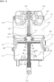
- FIG. 1 is a diagram showing a pneumatic spring brake chamber for a vehicle.
- a brake chamber for a vehicle In a pneumatic spring brake chamber for a vehicle, the air flow between a spring chamber 150 and a service chamber 310 is performed by means of a hollow actuator rod 120 disposed between the spring chamber 150 and the service chamber 310 and an actuator rod valve 121 coupled to a lower end of the actuator rod 120.
- the pneumatic spring brake chamber for a vehicle includes a hollow head housing 100, an adapter housing 200 and a bottom housing 300, arranged in order from the top.
- a piston 110 is disposed between the head housing 100 and the adapter housing 200, and a diaphragm 400 is disposed between the adapter housing 200 and the bottom housing 300.
- the actuator rod 120 having a hole formed through the adapter housing 200 is disposed below a piston hole formed in the piston 110, and a rod valve 121 is disposed at an end of the actuator rod 120.
- the rod valve 121 may allow the spring chamber 150 and the service chamber 310 to communicate with each other and thus allow air flow therebetween.
- the piston 110 and the actuator rod 120 are formed separately but may be integrally formed with each other.
- the spring chamber 150 is formed between the head housing 100 and the piston 110, and a pressure chamber 160 is formed between the piston 110 and the adapter housing 200.
- the service chamber 310 is formed between the adapter housing 200 and the diaphragm 400, and a push-rod chamber 320 is formed between the diaphragm 400 and the bottom housing 300.
- a compression spring 130 disposed in the spring chamber 150 is a coil spring, and the outer diameter of the coil may be gradually decreased from the center of the coil toward the both ends thereof. At this time, one end of the compression spring 130 is supported in contact with the piston 110, and the other end of the compression spring 130 is supported in contact with a bent portion of the head housing 100.
- the bent portion is formed at the upper end of the head housing 100 along an inner side of the head housing 100, and the bent portion prevents the compression spring 130 from moving at the upper portion so that the compression spring 130 is compressed while always maintaining a constant center axis.
- the piston 110 is in close contact with the inside of the head housing 100 to separate the inner space of the head housing 100 into the spring chamber 150 and the pressure chamber 160.
- the hollow actuator rod 120 is disposed in one direction along the piston hole. Thus, one end of the actuator rod 120 may be connected to the piston 110, and the other end may be supported on the diaphragm 400 through the hole of the adapter housing 200.
- a lip seal 122 is disposed at a portion where the outer circumference of the actuator rod 120 and the inner circumference of the adapter housing 200 are in contact with each other to prevent fluid leakage.
- a casing bolt 140 having one end fixed to a head housing hole of the head housing 100 and disposed through the adapter housing 300 and a casing nut 142 having the other end screwed to the casing bolt 140 are disposed inside the hollow actuator rod 120.
- the adapter housing 200 is disposed between the head housing 100 and the bottom housing 300 to connect the head housing 100 and the bottom housing 300 to each other.
- the adapter housing 200 has a hole at a center thereof, and the actuator rod 120 is supported in contact with the diaphragm 400 through the hole.
- the adapter housing 200 has a valve structure 210 at one side thereof to introduce air pressure, so that air may be introduced when a parking brake is operated while the vehicle is running.
- the diaphragm 400 is disposed in the bottom housing 300, and the diaphragm 400 is supported in contact with a push-rod plate 510 and divides the bottom housing 300 into the service chamber 310 and the push-rod chamber 320.
- the push-rod plate 510 is supported by the push-rod 500 and transmits the movement of the diaphragm 400 according to the air pressure to the push-rod 500.
- a return spring 520 is disposed between the push-rod plate 510 and the bottom housing 300 along an axial direction of the push-rod 500 and is compressed and restored as the push-rod plate 510 moves.
- the diaphragm 400 moves the push-rod plate 510 and the push-rod vertically according to the elastic force of the compression spring 130 in the spring chamber 150 and the air pressure adjustment in the pressure chamber 160, thereby operating a brake (not shown) connected to the lower end of the push-rod 500.
- a push-rod guide 610 for guiding the movement of the push-rod 500 moving along the push-rod hole 330 and a push-rod guide cover 620 for fixing the push-rod guide 610 are provided at the bottom surface of the bottom housing 300.
- the housing 300, the push-rod and the yoke may have various shapes, and the present disclosure is not limited to any specific shape.
- the push-rod guide 610 and the push-rod guide cover 620 will be explained in detail.
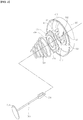
- FIG. 2 is an exploded perspective view showing that a push-rod guide and a push-rod guide cover are being coupled to a bottom housing according to an embodiment of the present disclosure
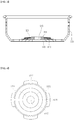
- FIG. 3 is a cross-sectioned view showing that the push-rod guide and the push-rod guide cover are coupled to the bottom housing according to an embodiment of the present disclosure
- FIG. 4 is a plane view showing that the push-rod guide and the push-rod guide cover are coupled according to an embodiment of the present disclosure.
- the push-rod 500 has a yoke 530 at an end thereof and is inserted into the push-rod hole 330. Since the yoke 530 has a larger diameter than the push-rod 500, a gap is formed between the outer circumference of the push-rod 500 and the push-rod hole 330 in a state where the push-rod 500 is inserted into the push-rod hole 330.
- the push-rod guide 610 guides the movement of the push-rod 500 while sealing the gap.
- the push-rod guide 610 is integrally formed by coupling a pair of half members 611, 612 of a semicircular plate shape by hinges.
- the pair of half members 611, 612 may be pivoted about a hinge shaft 613.
- semicircular cut portions 614 are formed in the half members 611, 612, respectively, and the semicircular cut portions 614 are adjacent to each other and coupled while facing each other to form a guide hole 615.
- the pair of half members 611, 612 in an opened state are engaged at the side of the push-rod 500 and pivoted to be coupled to each other, thereby forming the guide hole 615 in a closed shape.
- the guide hole 615 serves to guide the movement of the push-rod 500 at the bottom surface of the bottom housing 300.
- a protrusion 616 protruding upward is formed at a center of the push-rod guide 610 to form a step toward a radial direction of the push-rod guide 610.
- the protrusion 616 is coupled to an accommodation groove 621, explained later, formed in the push-rod guide cover 620.
- the push-rod guide cover 620 serves to fix the push-rod guide 610 to the bottom surface of the bottom housing 300.
- the inner diameter of the push-rod guide cover 620 is formed so that the outer circumference of the push-rod guide 610 may be accommodated therein.
- the outer circumference of the push-rod guide cover 620 may be fixed by the return spring 520 disposed between the push-rod plate 510 and the bottom housing 300. Accordingly, a predetermined pressure is applied to the outer circumference of the push-rod guide cover 620 by the return spring 520, and thus it is possible to prevent the push rod guide 610 and the push-rod guide cover 620 from moving.
- the push-rod guide cover 620 has the accommodation groove 621 formed at an inner circumference thereof to correspond to the step of the push-rod guide 610.
- the protrusion 616 formed on the push-rod guide 610 is inserted and fixed in the accommodation groove 621. Accordingly, the push-rod guide 610 is firmly fixed to the bottom surface of the bottom housing 300 without a separate coupling member such as a bolt.
- the push-rod guide 610 and the push-rod guide cover 620 may be made of a synthetic resin material with elasticity, and the pair of half members 611, 612 may be integrally formed by injection molding.
- the push-rod guide cover 620 may further include fixed wings 622 formed at the outer circumference thereof to protrude radially at intervals of at least 90 degrees.
- the fixed wings 622 may serve to more securely fix the push-rod guide 610 to the bottom surface of the bottom housing 300 by the return spring 520.
- the outer circumference of the push-rod guide cover 620 may have a spring-fixing step 623.
- the spring-fixing step 623 may prevent the return spring 520 from moving in a horizontal direction by forming a step portion in a radial direction.
- the push-rod guide 610 is formed by integrally injection-molding the pair of half members 611, 612 and the pair of half members 611, 612 are pivoted about the hinge shaft 613, the push-rod guide 610 may be easily fastened at the side of the push-rod 500.
- the push-rod guide 610 is inserted and fixed in the accommodation groove 621 formed in the push-rod guide cover 620, the push-rod guide 610 may maintain a firm coupling strength without a separate coupling member.
- a push-rod guide of an existing technique is formed with members separated from each other, and a coupling member such as a bolt is used for coupling the separated members.
- a coupling member such as a bolt
- the coupling member may be detached due to the vibration generated during the operation of the brake.
- the present disclosure is capable of solving the problems of the existing technique by using the above-described structural features.
- head housing 110 piston 120: actuator rod 130: compression spring 140: casing bolt 150: spring chamber 160: pressure chamber 200: adaptor housing 300: bottom housing 310: service chamber 320: push-rod chamber 400: diaphragm 500: push-rod 510: push-rod plate 520: return spring 530: yoke 610: push-rod guide 611, 612: half member 613: hinge shaft 614: semicircular cut portion 615: guide hole 616: protrusion 620: push-rod guide cover 621: step 622: fixed wing
Landscapes
- Engineering & Computer Science (AREA)
- Transportation (AREA)
- Mechanical Engineering (AREA)
- Braking Systems And Boosters (AREA)
Claims (2)
- Kopplungsstruktur einer Stößelstangenführung (610) und einer Stößelstangenführungsabdeckung (620) für eine Bremskammer für ein Fahrzeug, wobei die Bremskammer ein oberes Gehäuse (100), ein unteres Gehäuse (300), ein Adaptergehäuse (200), das zwischen dem oberen Gehäuse (100) und dem unteren Gehäuse (300) bereitgestellt ist, um das obere Gehäuse (100) und das untere Gehäuse (300) zu verbinden, eine Membran (400), die zwischen dem Adaptergehäuse (200) und dem unteren Gehäuse (300) befestigt ist, um einen Raum zwischen dem Adaptergehäuse (200) und dem unteren Gehäuse (300) zu trennen, eine Stößelstange (500), die konfiguriert ist, um eine untere Fläche der Membran (400) zu stützen und entlang eines Stößelstangenlochs (330) zu bewegen, das in einer Bodenfläche des unteren Gehäuses (300) ausgebildet ist, ein Joch (530), das mit einem Ende der Stößelstange (500) verbunden ist, und eine Rückstellfeder (520), die zwischen der Stößelstange (500) und dem unteren Gehäuse (300) angeordnet ist,
wobei nach der Einführung der Stößelstange (500) und des Jochs (530) in das Stößelstangenloch (330), die Stößelstangenführung (610) an einer axialen Seite der Stößelstange (500) an der Innenseite des unteren Gehäuses (300) angebracht wird und die Stößelstangenführungsabdeckung (620) mit der Stößelstangenführung (610) gekoppelt und von der Rückstellfeder (520) getragen wird, um die Stößelstangenführung (610) zu fixieren,
wobei die Stößelstangenführung (610) ein Paar Halbelemente (611, 612) mit einer halbkreisförmigen Plattenform umfasst, die durch ein Gelenk verbunden sind, das an der axialen Seite der Stößelstange (500) anzubringen ist, um eine kreisförmigen Plattenform zu bilden, und die Stößelstangenführung (610) eine Stößelstangenöffnung in der Mitte der kreisförmigen Platte aufweist, um eine Bewegung der Stößelstange (500) zu führen, und
wobei ein Vorsprung (616), der nach oben vorspringt, in der Mitte der Stößelstangenführung (610) bereitgestellt ist, um einen Schritt in einer radialen Richtung der Stößelstangenführung (610) zu bilden, und eine der Stufe entsprechende Unterbringungsrille (621) an einem Innenumfang der Stößelstangenführungsabdeckung (620) ausgebildet ist. - Kopplungsstruktur einer Stößelstangenführung (610) und einer Stößelstangenführungsabdeckung (620) einer Bremskammer für ein Fahrzeug nach Anspruch 1, wobei die Stößelstangenführung (610) aus einem Kunststoffmaterial besteht und die einen Enden des Paars von Halbelementen (611, 612) einstückig spritzgegossen sind, um das Gelenk zu bilden.
Priority Applications (1)
| Application Number | Priority Date | Filing Date | Title |
|---|---|---|---|
| EP17203236.9A EP3489102B1 (de) | 2017-11-23 | 2017-11-23 | Kupplungsstruktur einer schubstangenführung und einer schubstangenführungsabdeckung für eine bremskammer für ein fahrzeug |
Applications Claiming Priority (1)
| Application Number | Priority Date | Filing Date | Title |
|---|---|---|---|
| EP17203236.9A EP3489102B1 (de) | 2017-11-23 | 2017-11-23 | Kupplungsstruktur einer schubstangenführung und einer schubstangenführungsabdeckung für eine bremskammer für ein fahrzeug |
Publications (2)
| Publication Number | Publication Date |
|---|---|
| EP3489102A1 EP3489102A1 (de) | 2019-05-29 |
| EP3489102B1 true EP3489102B1 (de) | 2020-03-25 |
Family
ID=60515122
Family Applications (1)
| Application Number | Title | Priority Date | Filing Date |
|---|---|---|---|
| EP17203236.9A Active EP3489102B1 (de) | 2017-11-23 | 2017-11-23 | Kupplungsstruktur einer schubstangenführung und einer schubstangenführungsabdeckung für eine bremskammer für ein fahrzeug |
Country Status (1)
| Country | Link |
|---|---|
| EP (1) | EP3489102B1 (de) |
Family Cites Families (3)
| Publication number | Priority date | Publication date | Assignee | Title |
|---|---|---|---|---|
| CN2617950Y (zh) * | 2003-03-27 | 2004-05-26 | 张志平 | 筒式分泵 |
| CN2846243Y (zh) * | 2005-12-12 | 2006-12-13 | 瑞立集团有限公司 | 内呼吸式弹簧制动气室 |
| KR101567709B1 (ko) | 2014-07-11 | 2015-11-10 | (주)지앤피오토모티브 | 브레이크 액추에이터 |
-
2017
- 2017-11-23 EP EP17203236.9A patent/EP3489102B1/de active Active
Non-Patent Citations (1)
| Title |
|---|
| None * |
Also Published As
| Publication number | Publication date |
|---|---|
| EP3489102A1 (de) | 2019-05-29 |
Similar Documents
| Publication | Publication Date | Title |
|---|---|---|
| US9352631B2 (en) | Vehicle height adjusting device and assembling method for vehicle height adjusting device | |
| US9828981B2 (en) | Pump unit driven by an electric motor | |
| US20170355387A1 (en) | Tubular elastic linkage device for axle beam | |
| JP6625645B2 (ja) | プラスチックからなる少なくとも1つのハウジングを備える、車両圧縮空気設備用の圧縮空気供給装置 | |
| EP2511144B1 (de) | Fahrzeuglampen-Waschsystem und Düsenabdeckung | |
| US20170050628A1 (en) | Brake actuator | |
| US10239512B2 (en) | Engagement structure of push-rod guide and push-rod guide cover of brake chamber for vehicle | |
| EP3168100B1 (de) | Bremsaktuator mit dichtungsanordnung für interne luftzirkulation | |
| EP3581409B1 (de) | Luftregelventil, luftregelventilvorrichtung und kabinenaufhängungssystem und kraftfahrzeug | |
| EP3009707B1 (de) | Luftfederkolben mit integrierter dichtung | |
| EP3489102A1 (de) | Schubstangenführung und schubstangenführungsabdeckung einer bremskammer für ein fahrzeug | |
| US20040046296A1 (en) | Power unit mount structure for vehicles | |
| US20050236749A1 (en) | Cover assembly for a pneumatic spring | |
| JP5893728B2 (ja) | ブレーキシステムにおけるマスタシリンダアセンブリ | |
| KR101874398B1 (ko) | 차량용 브레이크 챔버의 푸시로드 가이드와 푸시로드 가이드 커버의 체결구조 | |
| US20260048634A1 (en) | Vibration proofing device | |
| CN103256272B (zh) | 气缸 | |
| KR101972248B1 (ko) | 성형 밀봉부들에 따라 가변적인 유동 연결부를 갖는 압축 공기 매체 장치 | |
| KR101778517B1 (ko) | 차량용 공기압 스프링 브레이크 챔버용 더블립 실링 | |
| CN223814360U (zh) | 脚制动阀 | |
| KR102820392B1 (ko) | 카운터 밸런스 장치 | |
| CN223635482U (zh) | 电磁阀 | |
| CN111663875A (zh) | 车辆前机盖总成和车辆 | |
| CN214945996U (zh) | 一种减震器阀座 | |
| KR20180057910A (ko) | 차량용 브레이크 챔버의 푸시로드 가이드의 구조 |
Legal Events
| Date | Code | Title | Description |
|---|---|---|---|
| PUAI | Public reference made under article 153(3) epc to a published international application that has entered the european phase |
Free format text: ORIGINAL CODE: 0009012 |
|
| STAA | Information on the status of an ep patent application or granted ep patent |
Free format text: STATUS: REQUEST FOR EXAMINATION WAS MADE |
|
| 17P | Request for examination filed |
Effective date: 20171212 |
|
| AK | Designated contracting states |
Kind code of ref document: A1 Designated state(s): AL AT BE BG CH CY CZ DE DK EE ES FI FR GB GR HR HU IE IS IT LI LT LU LV MC MK MT NL NO PL PT RO RS SE SI SK SM TR |
|
| AX | Request for extension of the european patent |
Extension state: BA ME |
|
| RBV | Designated contracting states (corrected) |
Designated state(s): AL AT BE BG CH CY CZ DE DK EE ES FI FR GB GR HR HU IE IS IT LI LT LU LV MC MK MT NL NO PL PT RO RS SE SI SK SM TR |
|
| GRAP | Despatch of communication of intention to grant a patent |
Free format text: ORIGINAL CODE: EPIDOSNIGR1 |
|
| STAA | Information on the status of an ep patent application or granted ep patent |
Free format text: STATUS: GRANT OF PATENT IS INTENDED |
|
| RIC1 | Information provided on ipc code assigned before grant |
Ipc: B60T 17/08 20060101AFI20190920BHEP |
|
| INTG | Intention to grant announced |
Effective date: 20191021 |
|
| GRAS | Grant fee paid |
Free format text: ORIGINAL CODE: EPIDOSNIGR3 |
|
| GRAA | (expected) grant |
Free format text: ORIGINAL CODE: 0009210 |
|
| STAA | Information on the status of an ep patent application or granted ep patent |
Free format text: STATUS: THE PATENT HAS BEEN GRANTED |
|
| AK | Designated contracting states |
Kind code of ref document: B1 Designated state(s): AL AT BE BG CH CY CZ DE DK EE ES FI FR GB GR HR HU IE IS IT LI LT LU LV MC MK MT NL NO PL PT RO RS SE SI SK SM TR |
|
| REG | Reference to a national code |
Ref country code: GB Ref legal event code: FG4D |
|
| REG | Reference to a national code |
Ref country code: AT Ref legal event code: REF Ref document number: 1248234 Country of ref document: AT Kind code of ref document: T Effective date: 20200415 Ref country code: IE Ref legal event code: FG4D |
|
| REG | Reference to a national code |
Ref country code: DE Ref legal event code: R096 Ref document number: 602017013555 Country of ref document: DE |
|
| PG25 | Lapsed in a contracting state [announced via postgrant information from national office to epo] |
Ref country code: NO Free format text: LAPSE BECAUSE OF FAILURE TO SUBMIT A TRANSLATION OF THE DESCRIPTION OR TO PAY THE FEE WITHIN THE PRESCRIBED TIME-LIMIT Effective date: 20200625 Ref country code: FI Free format text: LAPSE BECAUSE OF FAILURE TO SUBMIT A TRANSLATION OF THE DESCRIPTION OR TO PAY THE FEE WITHIN THE PRESCRIBED TIME-LIMIT Effective date: 20200325 Ref country code: RS Free format text: LAPSE BECAUSE OF FAILURE TO SUBMIT A TRANSLATION OF THE DESCRIPTION OR TO PAY THE FEE WITHIN THE PRESCRIBED TIME-LIMIT Effective date: 20200325 |
|
| PG25 | Lapsed in a contracting state [announced via postgrant information from national office to epo] |
Ref country code: LV Free format text: LAPSE BECAUSE OF FAILURE TO SUBMIT A TRANSLATION OF THE DESCRIPTION OR TO PAY THE FEE WITHIN THE PRESCRIBED TIME-LIMIT Effective date: 20200325 Ref country code: SE Free format text: LAPSE BECAUSE OF FAILURE TO SUBMIT A TRANSLATION OF THE DESCRIPTION OR TO PAY THE FEE WITHIN THE PRESCRIBED TIME-LIMIT Effective date: 20200325 Ref country code: HR Free format text: LAPSE BECAUSE OF FAILURE TO SUBMIT A TRANSLATION OF THE DESCRIPTION OR TO PAY THE FEE WITHIN THE PRESCRIBED TIME-LIMIT Effective date: 20200325 Ref country code: BG Free format text: LAPSE BECAUSE OF FAILURE TO SUBMIT A TRANSLATION OF THE DESCRIPTION OR TO PAY THE FEE WITHIN THE PRESCRIBED TIME-LIMIT Effective date: 20200625 Ref country code: GR Free format text: LAPSE BECAUSE OF FAILURE TO SUBMIT A TRANSLATION OF THE DESCRIPTION OR TO PAY THE FEE WITHIN THE PRESCRIBED TIME-LIMIT Effective date: 20200626 |
|
| REG | Reference to a national code |
Ref country code: NL Ref legal event code: MP Effective date: 20200325 |
|
| REG | Reference to a national code |
Ref country code: LT Ref legal event code: MG4D |
|
| PG25 | Lapsed in a contracting state [announced via postgrant information from national office to epo] |
Ref country code: NL Free format text: LAPSE BECAUSE OF FAILURE TO SUBMIT A TRANSLATION OF THE DESCRIPTION OR TO PAY THE FEE WITHIN THE PRESCRIBED TIME-LIMIT Effective date: 20200325 |
|
| PG25 | Lapsed in a contracting state [announced via postgrant information from national office to epo] |
Ref country code: SM Free format text: LAPSE BECAUSE OF FAILURE TO SUBMIT A TRANSLATION OF THE DESCRIPTION OR TO PAY THE FEE WITHIN THE PRESCRIBED TIME-LIMIT Effective date: 20200325 Ref country code: LT Free format text: LAPSE BECAUSE OF FAILURE TO SUBMIT A TRANSLATION OF THE DESCRIPTION OR TO PAY THE FEE WITHIN THE PRESCRIBED TIME-LIMIT Effective date: 20200325 Ref country code: EE Free format text: LAPSE BECAUSE OF FAILURE TO SUBMIT A TRANSLATION OF THE DESCRIPTION OR TO PAY THE FEE WITHIN THE PRESCRIBED TIME-LIMIT Effective date: 20200325 Ref country code: CZ Free format text: LAPSE BECAUSE OF FAILURE TO SUBMIT A TRANSLATION OF THE DESCRIPTION OR TO PAY THE FEE WITHIN THE PRESCRIBED TIME-LIMIT Effective date: 20200325 Ref country code: RO Free format text: LAPSE BECAUSE OF FAILURE TO SUBMIT A TRANSLATION OF THE DESCRIPTION OR TO PAY THE FEE WITHIN THE PRESCRIBED TIME-LIMIT Effective date: 20200325 Ref country code: PT Free format text: LAPSE BECAUSE OF FAILURE TO SUBMIT A TRANSLATION OF THE DESCRIPTION OR TO PAY THE FEE WITHIN THE PRESCRIBED TIME-LIMIT Effective date: 20200818 Ref country code: IS Free format text: LAPSE BECAUSE OF FAILURE TO SUBMIT A TRANSLATION OF THE DESCRIPTION OR TO PAY THE FEE WITHIN THE PRESCRIBED TIME-LIMIT Effective date: 20200725 Ref country code: SK Free format text: LAPSE BECAUSE OF FAILURE TO SUBMIT A TRANSLATION OF THE DESCRIPTION OR TO PAY THE FEE WITHIN THE PRESCRIBED TIME-LIMIT Effective date: 20200325 |
|
| REG | Reference to a national code |
Ref country code: AT Ref legal event code: MK05 Ref document number: 1248234 Country of ref document: AT Kind code of ref document: T Effective date: 20200325 |
|
| REG | Reference to a national code |
Ref country code: DE Ref legal event code: R097 Ref document number: 602017013555 Country of ref document: DE |
|
| PG25 | Lapsed in a contracting state [announced via postgrant information from national office to epo] |
Ref country code: ES Free format text: LAPSE BECAUSE OF FAILURE TO SUBMIT A TRANSLATION OF THE DESCRIPTION OR TO PAY THE FEE WITHIN THE PRESCRIBED TIME-LIMIT Effective date: 20200325 Ref country code: AT Free format text: LAPSE BECAUSE OF FAILURE TO SUBMIT A TRANSLATION OF THE DESCRIPTION OR TO PAY THE FEE WITHIN THE PRESCRIBED TIME-LIMIT Effective date: 20200325 Ref country code: IT Free format text: LAPSE BECAUSE OF FAILURE TO SUBMIT A TRANSLATION OF THE DESCRIPTION OR TO PAY THE FEE WITHIN THE PRESCRIBED TIME-LIMIT Effective date: 20200325 Ref country code: DK Free format text: LAPSE BECAUSE OF FAILURE TO SUBMIT A TRANSLATION OF THE DESCRIPTION OR TO PAY THE FEE WITHIN THE PRESCRIBED TIME-LIMIT Effective date: 20200325 |
|
| PLBE | No opposition filed within time limit |
Free format text: ORIGINAL CODE: 0009261 |
|
| STAA | Information on the status of an ep patent application or granted ep patent |
Free format text: STATUS: NO OPPOSITION FILED WITHIN TIME LIMIT |
|
| PG25 | Lapsed in a contracting state [announced via postgrant information from national office to epo] |
Ref country code: PL Free format text: LAPSE BECAUSE OF FAILURE TO SUBMIT A TRANSLATION OF THE DESCRIPTION OR TO PAY THE FEE WITHIN THE PRESCRIBED TIME-LIMIT Effective date: 20200325 |
|
| 26N | No opposition filed |
Effective date: 20210112 |
|
| PG25 | Lapsed in a contracting state [announced via postgrant information from national office to epo] |
Ref country code: SI Free format text: LAPSE BECAUSE OF FAILURE TO SUBMIT A TRANSLATION OF THE DESCRIPTION OR TO PAY THE FEE WITHIN THE PRESCRIBED TIME-LIMIT Effective date: 20200325 |
|
| PG25 | Lapsed in a contracting state [announced via postgrant information from national office to epo] |
Ref country code: MC Free format text: LAPSE BECAUSE OF FAILURE TO SUBMIT A TRANSLATION OF THE DESCRIPTION OR TO PAY THE FEE WITHIN THE PRESCRIBED TIME-LIMIT Effective date: 20200325 |
|
| REG | Reference to a national code |
Ref country code: CH Ref legal event code: PL |
|
| PG25 | Lapsed in a contracting state [announced via postgrant information from national office to epo] |
Ref country code: LU Free format text: LAPSE BECAUSE OF NON-PAYMENT OF DUE FEES Effective date: 20201123 |
|
| REG | Reference to a national code |
Ref country code: BE Ref legal event code: MM Effective date: 20201130 |
|
| PG25 | Lapsed in a contracting state [announced via postgrant information from national office to epo] |
Ref country code: LI Free format text: LAPSE BECAUSE OF NON-PAYMENT OF DUE FEES Effective date: 20201130 Ref country code: CH Free format text: LAPSE BECAUSE OF NON-PAYMENT OF DUE FEES Effective date: 20201130 |
|
| PG25 | Lapsed in a contracting state [announced via postgrant information from national office to epo] |
Ref country code: FR Free format text: LAPSE BECAUSE OF NON-PAYMENT OF DUE FEES Effective date: 20201130 Ref country code: IE Free format text: LAPSE BECAUSE OF NON-PAYMENT OF DUE FEES Effective date: 20201123 |
|
| PG25 | Lapsed in a contracting state [announced via postgrant information from national office to epo] |
Ref country code: TR Free format text: LAPSE BECAUSE OF FAILURE TO SUBMIT A TRANSLATION OF THE DESCRIPTION OR TO PAY THE FEE WITHIN THE PRESCRIBED TIME-LIMIT Effective date: 20200325 Ref country code: MT Free format text: LAPSE BECAUSE OF FAILURE TO SUBMIT A TRANSLATION OF THE DESCRIPTION OR TO PAY THE FEE WITHIN THE PRESCRIBED TIME-LIMIT Effective date: 20200325 Ref country code: CY Free format text: LAPSE BECAUSE OF FAILURE TO SUBMIT A TRANSLATION OF THE DESCRIPTION OR TO PAY THE FEE WITHIN THE PRESCRIBED TIME-LIMIT Effective date: 20200325 |
|
| PG25 | Lapsed in a contracting state [announced via postgrant information from national office to epo] |
Ref country code: MK Free format text: LAPSE BECAUSE OF FAILURE TO SUBMIT A TRANSLATION OF THE DESCRIPTION OR TO PAY THE FEE WITHIN THE PRESCRIBED TIME-LIMIT Effective date: 20200325 Ref country code: AL Free format text: LAPSE BECAUSE OF FAILURE TO SUBMIT A TRANSLATION OF THE DESCRIPTION OR TO PAY THE FEE WITHIN THE PRESCRIBED TIME-LIMIT Effective date: 20200325 |
|
| GBPC | Gb: european patent ceased through non-payment of renewal fee |
Effective date: 20211123 |
|
| PG25 | Lapsed in a contracting state [announced via postgrant information from national office to epo] |
Ref country code: BE Free format text: LAPSE BECAUSE OF NON-PAYMENT OF DUE FEES Effective date: 20201130 |
|
| PG25 | Lapsed in a contracting state [announced via postgrant information from national office to epo] |
Ref country code: GB Free format text: LAPSE BECAUSE OF NON-PAYMENT OF DUE FEES Effective date: 20211123 |
|
| PGFP | Annual fee paid to national office [announced via postgrant information from national office to epo] |
Ref country code: DE Payment date: 20251222 Year of fee payment: 9 |