EP3488973A1 - Wechselbacke für presswerkzeug - Google Patents
Wechselbacke für presswerkzeug Download PDFInfo
- Publication number
- EP3488973A1 EP3488973A1 EP18207507.7A EP18207507A EP3488973A1 EP 3488973 A1 EP3488973 A1 EP 3488973A1 EP 18207507 A EP18207507 A EP 18207507A EP 3488973 A1 EP3488973 A1 EP 3488973A1
- Authority
- EP
- European Patent Office
- Prior art keywords
- pressing
- attachment
- base jaw
- jaw
- base
- Prior art date
- Legal status (The legal status is an assumption and is not a legal conclusion. Google has not performed a legal analysis and makes no representation as to the accuracy of the status listed.)
- Granted
Links
Images


Classifications
-
- B—PERFORMING OPERATIONS; TRANSPORTING
- B25—HAND TOOLS; PORTABLE POWER-DRIVEN TOOLS; MANIPULATORS
- B25B—TOOLS OR BENCH DEVICES NOT OTHERWISE PROVIDED FOR, FOR FASTENING, CONNECTING, DISENGAGING OR HOLDING
- B25B27/00—Hand tools, specially adapted for fitting together or separating parts or objects whether or not involving some deformation, not otherwise provided for
- B25B27/02—Hand tools, specially adapted for fitting together or separating parts or objects whether or not involving some deformation, not otherwise provided for for connecting objects by press fit or detaching same
- B25B27/10—Hand tools, specially adapted for fitting together or separating parts or objects whether or not involving some deformation, not otherwise provided for for connecting objects by press fit or detaching same inserting fittings into hoses
-
- B—PERFORMING OPERATIONS; TRANSPORTING
- B21—MECHANICAL METAL-WORKING WITHOUT ESSENTIALLY REMOVING MATERIAL; PUNCHING METAL
- B21D—WORKING OR PROCESSING OF SHEET METAL OR METAL TUBES, RODS OR PROFILES WITHOUT ESSENTIALLY REMOVING MATERIAL; PUNCHING METAL
- B21D37/00—Tools as parts of machines covered by this subclass
- B21D37/04—Movable or exchangeable mountings for tools
-
- B—PERFORMING OPERATIONS; TRANSPORTING
- B21—MECHANICAL METAL-WORKING WITHOUT ESSENTIALLY REMOVING MATERIAL; PUNCHING METAL
- B21D—WORKING OR PROCESSING OF SHEET METAL OR METAL TUBES, RODS OR PROFILES WITHOUT ESSENTIALLY REMOVING MATERIAL; PUNCHING METAL
- B21D39/00—Application of procedures in order to connect objects or parts, e.g. coating with sheet metal otherwise than by plating; Tube expanders
- B21D39/04—Application of procedures in order to connect objects or parts, e.g. coating with sheet metal otherwise than by plating; Tube expanders of tubes with tubes; of tubes with rods
- B21D39/046—Connecting tubes to tube-like fittings
-
- B—PERFORMING OPERATIONS; TRANSPORTING
- B21—MECHANICAL METAL-WORKING WITHOUT ESSENTIALLY REMOVING MATERIAL; PUNCHING METAL
- B21D—WORKING OR PROCESSING OF SHEET METAL OR METAL TUBES, RODS OR PROFILES WITHOUT ESSENTIALLY REMOVING MATERIAL; PUNCHING METAL
- B21D39/00—Application of procedures in order to connect objects or parts, e.g. coating with sheet metal otherwise than by plating; Tube expanders
- B21D39/04—Application of procedures in order to connect objects or parts, e.g. coating with sheet metal otherwise than by plating; Tube expanders of tubes with tubes; of tubes with rods
- B21D39/048—Application of procedures in order to connect objects or parts, e.g. coating with sheet metal otherwise than by plating; Tube expanders of tubes with tubes; of tubes with rods using presses for radially crimping tubular elements
-
- F—MECHANICAL ENGINEERING; LIGHTING; HEATING; WEAPONS; BLASTING
- F16—ENGINEERING ELEMENTS AND UNITS; GENERAL MEASURES FOR PRODUCING AND MAINTAINING EFFECTIVE FUNCTIONING OF MACHINES OR INSTALLATIONS; THERMAL INSULATION IN GENERAL
- F16L—PIPES; JOINTS OR FITTINGS FOR PIPES; SUPPORTS FOR PIPES, CABLES OR PROTECTIVE TUBING; MEANS FOR THERMAL INSULATION IN GENERAL
- F16L33/00—Arrangements for connecting hoses to rigid members; Rigid hose-connectors, i.e. single members engaging both hoses
- F16L33/02—Hose-clips
Definitions
- the invention relates to an attachment for a base jaw of a pressing tool for pressing fittings for the production of pipe joints, wherein two base jaws and two attachments together form a pressing jaw of a pressing tool, with an attachment body, with a pressing portion formed on the attachment body for forming a half of a jaw mouth, which forms the receiving area for the fitting to be compressed, and with a connecting portion formed on the connecting portion for connecting to the base jaw.
- the invention also relates to a base jaw of a pressing tool for pressing fittings for producing pipe joints with a base jaw body, with a hinge-like receptacle for connection to another base jaw and with an interaction section for interaction with a pressing tool.
- the invention also relates to a system for pressing fittings for the production of pipe joints.
- the technical field relevant to the present invention is the on-site installation of piping systems, where a piping system consisting of pipe sections and fittings is generally installed for the routing and routing of a fluid.
- a fitting is basically understood a connector of a pipeline and is most often used to connect two or more pipe sections.
- the fitting accordingly has two or more pressing sections.
- the most common fittings include straight joints, pipe bends, reducers, branches such as tees or crossings. Under a fitting but is also a pipe connection of a valve or other component to understand.
- thermometers or pressure gauges as fittings have only one connection for a pipe section. Thus, this fitting then has only one pressing section to connect a pipe section to the fitting.
- press connections are used in which a press section of a fitting is inserted with plugged pipe section by means of a pressing tool radially inwardly so that a permanent and dense, possibly even insoluble connection is made.
- the fittings can be provided with a sealant, for example, with an O-ring, which ensures the tightness of the connection, or by means of a direct contact of the materials of the pipe section and the fitting, for example, metallic sealing.
- pressing technique for a radial forming of the pressing section are purely radially acting pressing systems as well as pressing systems in question, which use a radial-axial compression, wherein during the pressing operation, a part of the fitting is axially displaced, thereby causing a radial forming.
- the piping systems generally described above serve, in particular, for transporting drinking or heating water, gas for operating a heating system or industrial gases.
- interchangeable jaws are also referred to as interchangeable jaws and are used on site to be able to press fittings with different diameters with the same press tool.
- interchangeable attachments are provided on the two base jaws, which form a press jaw, which form different sized jaw mouths for the required nominal widths.
- the essays have for this purpose a part-cylindrical or semi-cylindrical shape, which on the outside have a connecting section for connection to a corresponding connecting section of the base jaw.
- the inner contour is then adapted to the nominal width to be achieved. It means that the attachments are different thicknesses for different nominal widths in the radial direction.
- the base jaw itself also forms a part-cylindrical or semi-cylindrical connecting portion, which serves to accommodate the various essays.
- the distal portion of the base jaw is therefore formed by the base jaw itself and is the same for all essays with different diameters.
- Fittings with different nominal diameters require differently sized pressing forces due to their different sizes. Therefore, the base jaws to which the attachments are attached must be designed for the maximum pressing force of the attachments to be used. This is especially true for the outer contour of the distal portion of the base jaw body surrounding the connecting portion. As a result, the size of the base jaw and thus also the combination of base jaw and attachment is determined by the largest pressing force to be achieved and is disproportionately large for use with small diameters. Therefore, the use of interchangeable jaws during the compression of fittings with small diameters to space problems, so there is a risk of improperly laying fittings and / or pressing can.
- the present invention the technical problem underlying essays for change jaws, base jaws and indicate systems that allow improved use for fittings with different diameters.
- the attachment itself forms the entire distal section of the composite pressing jaw, consisting of base jaw and attachment, and that the connection section of the attachment is detached from the cylindrical form of the jaw jaw.
- the interface formed by the connecting portion to the base jaw can thereby be arranged away from the region of the pressing portion, so that there are more options for the design of the essays for different nominal widths.
- the connecting portion By displacing the connecting portion away from the pressing portion, it is possible to adapt the size of the interconnected base jaw and attachment, in particular the outer contour in the region of the distal end and the connecting portion, to the pressing force to be applied.
- the essay for small nominal diameters can be made smaller overall, so that even fittings with small nominal diameters and a narrower arrangement can be reliably and simply compressed in the laying of pipes and fittings in a suitable manner.
- the pressing portion is integral, that is, made of the same material, or integrally formed as a separate element with the attachment body.
- each essay on a fixed pressing section and is used as a whole as a change jaw.
- the pressing surface of the pressing section of each attachment ie the actual pressing contour, corresponds in its dimensions to a nominal value of an outer diameter of a fitting.
- a matching attachment can be connected as a jaw with the base jaw for each nominal size.
- the connecting section preferably forms a substantially planar interface with the base jaw.
- the formation of the interface in a substantially planar form is understood to mean that the interface has no part-cylindrical or semi-cylindrical shape. Substantially even further means that the interface does not have to have a smooth planar shape, but can be of stepped construction and has connection means explained below.
- a substantially planar shape thus means a non-curved shape with a longitudinal extent.
- the connecting portion may have connecting means for a positive, non-rotatable and releasable connection with the base jaw.
- Corresponding connection means are then also present on the base jaw, which are thus formed in a matrix or patrizenförmig.
- the connecting means can be mutually engaged by a simple movement, to allow easy replacement of essays on base jaws.
- the connecting means by means of a rotary movement or by means of a linear sliding movement in engagement with the formed on the base jaw connecting means can be brought.
- an exchange of articles can be carried out by means of a simple hand movement.
- the connecting means on a cylindrical recess for receiving a formed on the base jaw cylindrical pin or a cylindrical pin.
- the alternative formulation is intended to make it clear that the connection means on the attachment and on the base jaw correspond with each other and can be designed optionally on one side or the other. For attaching and detaching the attachment relative to the base jaw sufficient simple manual rotational movement.
- the connecting means may further comprise an undercut positioning element and a stop element.
- the positioning element and the stop element engage with the corresponding elements on the base jaw and allow a exact positioning and if necessary fixation of the attachment on the base jaw.
- the connecting means have an inlet rail for guiding at least one positioning element and / or stop element formed on the base jaw or at least one positioning element and / or stop element.
- the alternative formulation is intended to characterize a mutual formation of the connecting means both on the attachment and on the base jaw.
- This embodiment of the connecting means allows a replacement of the essay by a simple linear sliding movement.
- a fixing arrangement for releasably fixing the connecting means may be provided in the engaged position.
- the fixation arrangement can accomplish the fixation purely mechanically, for example by mutual locking or by means of magnetic elements.
- a base jaw of a pressing tool for pressing fittings for the production of pipe joints, again forming two base jaws a pressing jaw of a pressing tool.
- the base jaw on a base jaw body, a hinge-like receptacle for connection with another base jaw and an interaction section, for example, an inlet contour for the propulsion of a plunger, for an interaction with a pressing tool.
- the receptacle is preferably a bore for receiving a rotation axis of the pressing jaw with a holder with a rotation axis or with two axes of rotation.
- the base jaw according to a connecting portion for connecting to a previously discussed article and further, the connecting portion is formed complementary to the connecting portion of the essay.
- various attachments can be easily connected to the base jaw, so that with the one and the same base jaw different attachments can be connected.
- each attachment can be attached with its connecting means to each base jaw. This achieves the simplification that a user does not have to select whether a particular type of attachment must be attached to a particular type of base jaw.
- the attachments of different pairs of attachments have a size and outer contour adapted to the nominal size of the jaw mouths to be formed.
- the possibility of adapting the outer contour turns out to be advantageous. Because for small diameters, so for the compression of fittings with small dimensions, the space occupied by the essay and in particular by the distal portion of the attachment body space can be kept low. Thus, there are fewer problems in cramping areas for compacting fittings with small dimensions.
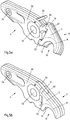
- the Fig. 1 and 2 show a first embodiment of an attachment 2 according to the invention for a in the 3 and 4 shown base jaw 4 of a pressing tool for pressing fittings for the production of pipe joints.
- two base jaws 4 together with two essays 2 form a pressing jaw of a pressing tool.
- the attachment 2 has an attachment body 6, on which a pressing portion 8 is formed for forming one half of a jaw mouth 10.
- the jaw mouth 10 forms the receiving area for the fitting to be compressed (not shown), in that the inner pressing surface or pressing contour 12 receives the fitting, bears against the latter and is at least partially deformed during pressing.
- a connecting portion 14 for connecting to the base jaw 4 is formed on the attachment body 6.
- the distal portion of the pressing jaw can be designed so that, in particular for small-diameter fittings, by a suitable design of the construction of the attachment body 6, the attachment body 6 represents the entire distal portion of the assembled pressing jaw Handling of the pressing jaw is facilitated.
- the pressing portion 8 and the connecting portion 14 are further spaced from each other.
- the interface between the attachment 2 and the base jaw 4 is arranged separately from the pressing section 8.
- the connecting portion 14 forms an at least partially substantially planar interface with the base jaw 4.
- the pressing portion 8 is integrally formed with the attachment body 2.
- Each article thus has a predetermined pressing section 8 with a pressing surface or pressing contour 12 with a predetermined nominal width.
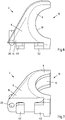
- the connecting portion 14 has connecting means for a positive, rotationally secure and detachable connection with the base jaw 4. These connecting means are formed in a matrix or patrizenförmig, so correspond to each other.
- the connecting means by means of a rotational movement into engagement with the formed on the base jaw 4 connecting means engageable.
- the connecting means have for this purpose a cylindrical recess 16 for receiving a formed on the base jaw 4 cylindrical pin 18, see 3 and 4 ,
- the connecting means have an undercut positioning element 20 and a stop element 22 which cooperate with a corresponding positioning element 24 and an undercut stop element 26 on the base jaw.
- the in the 3 and 4 illustrated base jaw 4 of a pressing tool for pressing fittings for the production of pipe joints has over the features described so far a base jaw body 30 with a hinge-like receptacle 32 for connection to another base jaw 4, wherein the receptacle 32 is formed as a bore for receiving a rotation axis.
- the pressing tool has for this purpose two axes of rotation or only one axis of rotation, which are fastened by a holder on both sides.
- the base jaw body 30 on an interaction section 34, in this case formed as a bore to be moved via a hinged lever (not shown).
- the interaction section 34 is configured to interact with a press tool that moves the described lever.
- the base jaw body 30 has a connecting portion 36 for connecting to one in the Fig. 1 and 2 shown essay 2, wherein the connecting portion 36 is complementary to the connecting portion 14 of the attachment 2 and the previously described elements cylindrical pin 18, positioning member 24 and stop member 26 has.
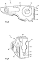
- FIG. 6 to 11 show a further embodiment of an attachment 2 and a base jaw 4, wherein like reference numerals designate like elements, as previously described with reference to FIG Fig. 1 to 5 have been described.
- the connecting means can be brought into engagement by means of a linear sliding movement.
- an undercut positioning element 40 and a also undercut stop member 42 is formed, which in the 6 and 7 can be seen.
- an inlet rail 44 with an inlet contour 46, the insertion contour 48 and a stop 50 is formed on the connecting portion 36 of the base jaw 4.
- the inlet rail 44 of the base jaw 4 forms a guide of the attachment 2 formed on the positioning member 40 and the stopper member 42nd
- a fixing arrangement is provided with a spring-loaded, arranged on the attachment body 6 ball 28 and formed on the base jaw 4 recess 28 'for releasably fixing the connecting means described in its engaged position.
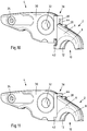
- the 10 and 11 show the connection of the above-described article 2 with the corresponding base jaw 4th
- Fig. 10 shows the insertion of the attachment 2 with the connecting elements 40 and 42, which are only partially visible, in the formed on the base jaw 4 guide rail 44.
- the positioning element 40 is guided through the insertion contour 48, while the stop element 42 with the inlet contour 46th is brought into contact.
- After insertion of the attachment 2 is linearly moved to the base jaw 4 to the in Fig. 11 take position shown.
- Fig. 12 shows a system for pressing fittings for the production of pipe joints with three pairs of essays 2 and with a pair of base jaws 4.
- the base jaws 4 are assembled by means of a holder 60 and two axes 62 and 64 to a pressing jaw 66 and by a pressing tool (not shown) are driven by a manual or motor drive.
- Different pairs of attachments 2 have pressing sections 8 for jaws 10 having different nominal diameters and the pairs of attachments 2 have identical connecting sections 14.
- the attachments 2 are adapted to be connected to the one pair of base jaws 4.
- the attachments 2 different pairs of essays then have an adapted to the nominal diameter of the trainees Jaws jaw 10 size and outer contour, especially for small diameters lead to small sizes, especially in the region of the distal portion of the attachment body 6 and in the region of the pressing section 8.
Landscapes
- Engineering & Computer Science (AREA)
- Mechanical Engineering (AREA)
- Mutual Connection Of Rods And Tubes (AREA)
- Automatic Assembly (AREA)
- Scissors And Nippers (AREA)
- Quick-Acting Or Multi-Walled Pipe Joints (AREA)
Abstract
Description
- Die Erfindung betrifft einen Aufsatz für eine Grundbacke eines Presswerkzeugs zum Verpressen von Fittings zur Herstellung von Rohrverbindungen, wobei zwei Grundbacken und zwei Aufsätze zusammen eine Pressbacke eines Presswerkzeugs bilden, mit einem Aufsatzkörper, mit einem am Aufsatzkörper ausgebildeten Pressabschnitt für ein Ausbilden einer Hälfte eines Backenmauls, das den Aufnahmebereich für den zu verpressenden Fitting bildet, und mit einem am Aufsatzkörper ausgebildeten Verbindungsabschnitt zum Verbinden mit der Grundbacke. Die Erfindung betrifft auch eine Grundbacke eines Presswerkzeugs zum Verpressen von Fittings zur Herstellung von Rohrverbindungen mit einem Grundbackenkörper, mit einer gelenkartigen Aufnahme für ein Verbinden mit einer weiteren Grundbacke und mit einen Wechselwirkungsabschnitt für eine Wechselwirkung mit einem Presswerkzeug. Die Erfindung betrifft auch ein System zum Verpressen von Fittings zur Herstellung von Rohrverbindungen.
- Der für die vorliegende Erfindung relevante technische Bereich ist die baustellenseitige Installation von Rohrleitungssystemen, bei der allgemein für das Leiten und Führen eines Fluids ein aus Rohrabschnitten und Fittings bestehendes Rohrleitungssystem installiert wird. Als Fitting wird grundsätzlich ein Verbindungsstück einer Rohrleitung verstanden und wird am häufigsten zur Verbindung von zwei oder mehreren Rohrabschnitten eingesetzt. Das Fitting weist dementsprechend zwei oder mehr Pressabschnitte auf. Zu den häufigsten Fittings zählen gerade Verbindungen, Richtungswechsel in Form von Rohrbögen, Reduzierstücke, Abzweige wie T-Stücke oder Kreuzungen. Unter einem Fitting ist aber auch ein Rohranschluss einer Armatur oder einer sonstigen Komponente zu verstehen. Beispielsweise weisen Thermometer oder Manometer als Armaturen nur einen Anschluss für einen Rohrabschnitt auf. Somit weist dieser Fitting dann nur einen Pressabschnitt auf, um einen Rohrabschnitt an der Armatur anzuschließen.
- Für das Verbinden der Rohrabschnitte mit den Fittings und sonstigen Komponenten werden Pressverbindungen genutzt, bei denen ein Pressabschnitt eines Fittings bei eingestecktem Rohrabschnitt mittels eines Presswerkzeugs radial nach innen so umgeformt wird, dass eine dauerhafte und dichte, gegebenenfalls sogar unlösbare Verbindung hergestellt wird. Die Fittings können dabei mit einem Dichtungsmittel, beispielsweise mit einem O-Ring, versehen sein, das die Dichtheit der Verbindung gewährleistet, oder auch mittels eines direkten Kontakts der Materialien des Rohrabschnitts und des Fittings, beispielweise metallisch dichtend ausgebildet sein.
- Als Presstechnik für ein radiales Umformen des Pressabschnittes kommen rein radial wirkende Presssysteme als auch Presssysteme in Frage, die ein radial-axiales Verpressen nutzen, wobei während des Pressvorgangs ein Teil des Fittings axial verschoben wird, um dadurch ein radiales Umformen zu bewirken.
- Die zuvor allgemein beschriebenen Rohrleitungssysteme dienen insbesondere einem Transport von Trink- oder Heizungswasser, von Gas zum Betrieb einer Heizungsanlage oder von Industriegasen.
- Die eingangs beschriebenen Aufsätze für jeweils eine Grundbacke werden auch als Wechselbacken bezeichnet und werden baustellenseitig verwendet, um Fittings mit unterschiedlichen Nennweiten mit dem gleichen Presswerkzeug verpressen zu können. Dazu sind an den beiden Grundbacken, die eine Pressbacke bilden, austauschbare Aufsätze vorgesehen, die für die benötigten Nennweiten unterschiedlich große Backenmäuler ausbilden.
- Die Aufsätze weisen dazu eine teilzylindrische bzw. halbzylindrische Form auf, die außenseitig einen Verbindungsabschnitt zum Verbinden mit einem korrespondierenden Verbindungsabschnitt der Grundbacke aufweisen. Die Innenkontur ist dann an die zu erreichende Nennweite angepasst. Das bedeutet, dass die Aufsätze für unterschiedliche Nennweiten in radialer Richtung unterschiedlich dick sind.
- Die Grundbacke selbst bildet ebenfalls einen teilzylindrischen bzw. halbzylindrischen Verbindungsabschnitt aus, der zur Aufnahme der verschiedenen Aufsätze dient. Der distale Abschnitt der Grundbacke wird daher von dem Grundbackenkörper selbst gebildet und ist für alle Aufsätze mit verschiedenen Nennweiten gleich ausgebildet.
- Fittings mit unterschiedlichen Nennweiten benötigen aufgrund ihrer unterschiedlichen Größen unterschiedlich große Presskräfte. Daher müssen die Grundbacken, an denen die Aufsätze befestigt werden, für die maximale Presskraft der zu verwendenden Aufsätze ausgelegt sein. Dieses gilt insbesondere auch für die Außenkontur des distalen Abschnitts des Grundbackenkörpers, der den Verbindungsabschnitt umgibt. Dadurch wird die Baugröße der Grundbacke und somit auch der Kombination aus Grundbacke und Aufsatz durch die größte zu erzielende Presskraft bestimmt und ist für den Einsatz bei kleinen Nennweiten unverhältnismäßig groß. Daher kommt es bei der Verwendung von Wechselbacken beim Verpressen von Fittings mit kleinen Nennweiten zu Platzproblemen, so dass die Gefahr besteht, Fittings nicht sachgemäß verlegen und/oder verpressen zu können.
- Zuvor beschriebene Aufsätze und Grundbacken sind in der
EP 0 826 441 B1 offenbart. - Daher liegt der vorliegenden Erfindung das technische Problem zugrunde, Aufsätze für Wechselbacken, Grundbacken und Systeme anzugeben, die einen verbesserten Einsatz für Fittings mit unterschiedlichen Nennweiten ermöglichen.
- Das zuvor aufgeführte technische Problem wird erfindungsgemäß zunächst bei einem eingangs genannten Aufsatz für eine Grundbacke eines Presswerkzeugs zum Verpressen von Fittings zur Herstellung von Rohrverbindungen dadurch gelöst, dass der Pressabschnitt und der Verbindungsabschnitt beabstandet zueinander angeordnet sind.
- Erfindungsgemäß ist erkannt worden, dass der Aufsatz selber den gesamten distalen Abschnitt der zusammengesetzten Pressbacke bestehend aus Grundbacke und Aufsatz bildet und dass der Verbindungsabschnitt des Aufsatzes von der zylindrischen Form des Backenmauls gelöst wird. Die vom Verbindungsabschnitt gebildete Schnittstelle zur Grundbacke kann dadurch vom Bereich des Pressabschnitts entfernt angeordnet werden, so dass sich mehr Optionen für die Ausgestaltung der Aufsätze für unterschiedliche Nennweiten ergeben.
- Durch die Verlagerung des Verbindungsabschnitts weg von dem Pressabschnitt ist es möglich, die Baugröße der miteinander verbundenen Grundbacke und Aufsatz, insbesondere die Außenkontur im Bereich des distalen Endes und des Verbindungsabschnitts, an die anzuwendende Presskraft anzupassen. Dadurch kann der Aufsatz für kleine Nennweiten insgesamt kleiner ausgebildet werden, so dass auch Fittings mit kleinen Nennweiten und engerer Anordnung beim Verlegen von Rohren und Armaturen in geeigneter Weise zuverlässig und einfach verpresst werden können.
- In bevorzugter Weise ist der Pressabschnitt integral, also aus dem gleichen Material bestehend, bzw. integriert als separates Element mit dem Aufsatzkörper ausgebildet. Somit weist jeder Aufsatz einen festen Pressabschnitt auf und wird als Ganzes als Wechselbacke genutzt.
- Des Weiteren entspricht die Pressfläche des Pressabschnitts jedes Aufsatzes, also die eigentliche Presskontur, in ihren Abmessungen einem Nennwert eines Außendurchmessers eines Fittings. Somit kann für jede Nennweite ein passender Aufsatz als Wechselbacke mit der Grundbacke verbunden werden.
- Bevorzugt bildet der Verbindungsabschnitt zumindest abschnittsweise eine im Wesentlichen ebene Schnittstelle zur Grundbacke. Die Ausbildung der Schnittstelle in einer im Wesentlichen ebenen Form wird dabei so verstanden, dass die Schnittstelle keine teilzylindrische oder halbzylindrische Form aufweist. Im Wesentlichen eben bedeutet weiterhin, dass die Schnittstelle nicht eine glatte ebene Form aufweisen muss, sondern gestuft ausgebildet sein kann und im Folgenden erläuterte Verbindungsmittel aufweist. Eine im Wesentlichen ebene Form bedeutet also eine nicht gekrümmte Form mit einer Längserstreckung.
- Weiterhin kann der Verbindungsabschnitt Verbindungsmittel für eine formschlüssige, verdrehsichere und lösbare Verbindung mit der Grundbacke aufweisen. Entsprechende Verbindungsmittel sind dann auch an der Grundbacke vorhanden, die somit matrizen- oder patrizenförmig ausgebildet sind. Dabei können die Verbindungsmittel gegenseitig durch eine einfache Bewegung miteinander in Eingriff gebracht werden, um ein leichtes Auswechseln von Aufsätzen an Grundbacken zu ermöglichen.
- In bevorzugter Weise sind die Verbindungsmittel mittels einer Drehbewegung oder mittels einer linearen Schiebebewegung in Eingriff mit den an der Grundbacke ausgebildeten Verbindungsmitteln bringbar. Somit kann mittels einer einfachen Handbewegung ein Austausch von Aufsätzen durchgeführt werden.
- Bei einer ersten bevorzugten Ausgestaltung der Verbindungsmittel weisen die Verbindungsmittel eine zylindrische Vertiefung zur Aufnahme eines an der Grundbacke ausgebildeten zylindrischen Stiftes oder einen zylindrischen Stift auf. Die alternative Formulierung soll dabei verdeutlichen, dass die Verbindungsmittel an dem Aufsatz und an der Grundbacke miteinander korrespondieren und wahlweise auf der einen oder anderen Seite ausgebildet sein können. Für das Anbringen und Lösen des Aufsatzes relativ zur Grundbacke reicht eine einfache manuelle Drehbewegung aus.
- Die Verbindungsmittel können weiterhin ein hinterschnittenes Positionierungselement und ein Anschlagselement aufweisen. Das Positionierungselement und das Anschlagselement kommen mit den korrespondierenden Elementen an der Grundbacke in Eingriff und ermöglichen eine exakte Positionierung und gegebenenfalls auch Fixierung des Aufsatzes an der Grundbacke.
- Bei einer zweiten bevorzugten Ausgestaltung der Verbindungsmittel weisen die Verbindungsmittel eine Einlaufschiene zur Führung mindestens eines an der Grundbacke ausgebildeten Positionierungselement und/oder Anschlagelements oder mindestens ein Positionierungselement und/oder Anschlagelement auf. Auch hierbei soll die alternative Formulierung eine wechselseitige Ausbildung der Verbindungsmittel sowohl an dem Aufsatz als auch an der Grundbacke kennzeichnen. Diese Ausgestaltung der Verbindungsmittel ermöglicht eine Auswechslung des Aufsatzes durch eine einfache lineare Schiebebewegung.
- Zudem kann eine Fixierungsanordnung für ein lösbares Fixieren der Verbindungsmittel in der Eingriffsposition vorgesehen sein. Die Fixierungsanordnung kann dabei rein mechanisch beispielsweise durch ein gegenseitiges Verrasten oder mittels magnetischer Elemente die Fixierung bewerkstelligen.
- Das oben aufgezeigte technische Problem wird erfindungsgemäß auch durch eine Grundbacke eines Presswerkzeugs zum Verpressen von Fittings zur Herstellung von Rohrverbindungen gelöst, wobei erneut zwei Grundbacken eine Pressbacke eines Presswerkzeugs bilden. Dazu weist die Grundbacke einen Grundbackenkörper, eine gelenkartige Aufnahme für ein Verbinden mit einer weiteren Grundbacke und eine Wechselwirkungsabschnitt, beispielsweise eine Einlaufkontur für den Vortrieb eines Presskolbens, für eine Wechselwirkung mit einem Presswerkzeug auf. Die Aufnahme ist dabei bevorzugt eine Bohrung zur Aufnahme einer Drehachse der Pressbacke mit einer Halterung mit einer Drehachse oder mit zwei Drehachsen.
- Zunächst weist die Grundbacke einen Verbindungsabschnitt zum Verbinden mit einem zuvor erläuterten Aufsatz nach und weiterhin ist der Verbindungsabschnitt komplementär zum Verbindungsabschnitt des Aufsatzes ausgebildet. Somit können verschiedene Aufsätze in einfacher Weise mit der Grundbacke verbunden werden, so das mit ein und der gleichen Grundbacke verschiedene Aufsätze verbunden werden können.
- Besonders vorteilhaft ist dabei, wenn die Verbindungsmittel an jeder von zwei Grundbacken, die zu einem Paar von Grundbacken zu einer Pressbacke zusammengebracht werden, gleich ausgebildet sind und jeder Aufsatz mit seinen Verbindungsmitteln an jeder Grundbacke befestigt werden kann. Dadurch wird die Vereinfachung erreicht, dass ein Benutzer nicht auswählen muss, ob ein bestimmter Typ eines Aufsatzes an einem bestimmten Typ einer Grundbacke angebracht werden muss.
- Das oben aufgezeigte technische Problem wird erfindungsgemäß auch durch ein System zum Verpressen von Fittings zur Herstellung von Rohrverbindungen, mit mindestens zwei Paaren von ebenfalls zuvor beschriebenen Aufsätzen und mit einem Paar von zuvor beschriebenen Grundbacken gelöst, wobei verschiedene Paare von Aufsätzen Pressabschnitte für Backenmäuler mit unterschiedlichen Nennweiten aufweisen und wobei die Paare von Aufsätzen gleiche Verbindungsabschnitte aufweisen. Die Vorteile eines solchen Systems sind bereits durch die vorige Beschreibung erläutert worden.
- In bevorzugter Weise weisen die Aufsätze unterschiedlicher Paare von Aufsätzen ein an die Nennweite der auszubildenden Backenmäuler angepasste Baugröße und Außenkontur auf. Dabei stellt sich insbesondere die Möglichkeit, die Außenkontur anzupassen, als vorteilhaft heraus. Denn für kleine Nennweiten, also für das Verpressen von Fittings mit kleinen Abmessungen, kann der vom Aufsatz und insbesondere der vom distalen Abschnitt des Aufsatzkörpers eingenommene Bauraum gering gehalten werden. Somit ergeben sich in beengten Bereichen für das Verpressen von Fittings mit kleinen Abmessungen geringere Probleme.
- Im Folgenden wird die Erfindung anhand von Ausführungsbeispielen mit Bezug auf die Zeichnung erläutert. In der Zeichnung zeigen
- Fig. 1
- ein erstes Ausführungsbeispiel eines Aufsatzes in einer Seitenansicht,
- Fig. 2
- den Aufsatz nach
Fig. 1 in einer Ansicht von schräg vorne, - Fig. 3
- ein erstes Ausführungsbeispiel einer Grundbacke in einer Seitenansicht,
- Fig. 4
- die Grundbacke nach
Fig. 3 in einer Ansicht von schräg vorne, - Fig. 5
- eine Anordnung aus Aufsatz und Grundbacke während des Zusammenbaus,
- Fig. 6
- ein zweites Ausführungsbeispiel eines Aufsatzes in einer Seitenansicht,
- Fig. 7
- den Aufsatz nach
Fig. 6 in einer Ansicht von schräg vorne, - Fig. 8
- ein zweites Ausführungsbeispiel einer Grundbacke in einer Seitenansicht,
- Fig. 9
- die Grundbacke nach
Fig. 8 in einer Ansicht von schräg vorne, - Fig. 10
- eine Anordnung aus Aufsatz und Grundbacke nach den
Fig. 6 bis 8 während des Zusammenbaus, - Fig. 11
- die Anordnung nach
Fig. 10 im zusammengefügten Zustand und - Fig. 12
- ein Ausführungsbeispiel eines Systems zum Verpressen von Fittings zur Herstellung von Rohrverbindungen.
- In der nachfolgenden Beschreibung der verschiedenen erfindungsgemäßen Ausführungsbeispiele werden Bauteile und Elemente mit gleicher Funktion und gleicher Wirkungsweise mit denselben Bezugszeichen versehen, auch wenn die Bauteile und Elemente bei den verschiedenen Ausführungsbeispielen in ihrer Dimension oder Form Unterschiede aufweisen können.
- Die
Fig. 1 und 2 zeigen ein erstes Ausführungsbeispiel eines erfindungsgemäßen Aufsatzes 2 für eine in denFig. 3 und 4 gezeigten Grundbacke 4 eines Presswerkzeugs zum Verpressen von Fittings zur Herstellung von Rohrverbindungen. Dabei bilden jeweils zwei Grundbacken 4 zusammen mit zwei Aufsätzen 2 eine Pressbacke eines Presswerkzeugs. - Der Aufsatz 2 weist einen Aufsatzkörper 6 auf, an dem ein Pressabschnitt 8 für ein Ausbilden einer Hälfte eines Backenmauls 10 ausgebildet ist. Das Backenmaul 10 bildet den Aufnahmebereich für den zu verpressenden Fitting (nicht dargestellt), indem die innen liegende Pressfläche bzw. Presskontur 12 den Fitting aufnimmt, an diesem anliegt und bei Verpressen zumindest teilweise verformt. Des Weiteren ist am Aufsatzkörper 6 ein Verbindungsabschnitt 14 zum Verbinden mit der Grundbacke 4 ausgebildet.
- Wie sich aus der Zusammenschau der
Fig. 1 bis 5 ergibt, stellt der Aufsatzkörper 6 den gesamten distalen Abschnitt der zusammengesetzten Pressbacke bestehend aus Aufsatz 2 und Grundbacke 4 dar. Daher kann durch eine geeignete Ausgestaltung der Bauform des Aufsatzkörpers 6 der distale Abschnitt der Pressbacke so gestaltet werden, dass insbesondere bei Fittings mit kleinen Nennweiten die Handhabung der Pressbacke erleichtert wird. - Der Pressabschnitt 8 und der Verbindungsabschnitt 14 sind weiterhin beabstandet zueinander angeordnet. Somit ist die Schnittstelle zwischen dem Aufsatz 2 und der Grundbacke 4 von dem Pressabschnitt 8 getrennt angeordnet. Des Weiteren bildet der Verbindungsabschnitt 14 eine zumindest abschnittsweise im Wesentlichen ebene Schnittstelle zur Grundbacke 4.
- Wie sich aus den
Fig. 1 und 2 ergibt, ist der Pressabschnitt 8 integral mit dem Aufsatzkörper 2 ausgebildet. Jeder Aufsatz hat also einen vorgegebenen Pressabschnitt 8 mit einer Pressfläche bzw. Presskontur 12 mit vorgegebener Nennweite. - Wie im Weiteren erläutert wird, weist der Verbindungsabschnitt 14 Verbindungsmittel für eine formschlüssige, verdrehsichere und lösbare Verbindung mit der Grundbacke 4 auf. Diese Verbindungsmittel sind matrizen- bzw. patrizenförmig ausgebildet, korrespondieren also miteinander.
- Bei dem in den
Fig. 1 und 2 dargestellten Ausführungsbeispiel des Aufsatzes 2 sind die Verbindungsmittel mittels einer Drehbewegung in Eingriff mit den an der Grundbacke 4 ausgebildeten Verbindungsmitteln in Eingriff bringbar. Die Verbindungsmittel weisen dazu eine zylindrische Vertiefung 16 zur Aufnahme eines an der Grundbacke 4 ausgebildeten zylindrischen Stiftes 18 auf, sieheFig. 3 und 4 . - Des Weiteren weisen die Verbindungsmittel ein hinterschnittenes Positionierungselement 20 und ein Anschlagselement 22 auf, die mit einem korrespondierenden Positionierungselement 24 und einem hinterschnittenen Anschlagelement 26 an der Grundbacke zusammenwirken.
- In
Fig. 5 ist zu erkennen, wie durch Einsetzen des zylindrischen Stiftes in die zylindrische Vertiefung (beides verborgen) der Aufsatz 2 in einer verdrehten Position an der Grundbacke 4 angesetzt wird, um nachfolgend durch eine Drehung in die Endposition gebracht werden kann. Dadurch kommen die beschriebenen Verbindungsmittel in Eingriff miteinander und bewirken eine drehfeste Positionierung des Aufsatzes 2 auf der Grundbacke 4. - Schließlich ist noch eine Fixierungsanordnung mit einem an der Grundbacke 4 befestigten schwenkbaren Hebel 26 und einer am Aufsatzkörper 6 ausgebildeten Vertiefung 26' vorgesehen, die die Grundbacke 4 und den Aufsatzkörper 6 im zusammengefügten Zustand in der Eingriffsposition lösbar fixieren.
- Die in den
Fig. 3 und 4 dargestellte Grundbacke 4 eines Presswerkzeugs zum Verpressen von Fittings zur Herstellung von Rohrverbindungen weist über die bisher beschriebenen Merkmale hinaus einen Grundbackenkörper 30 mit einer gelenkartigen Aufnahme 32 für ein Verbinden mit einer weiteren Grundbacke 4, wobei die Aufnahme 32 als Bohrung zur Aufnahme einer Drehachse ausgebildet ist. Das Presswerkzeug weist dazu zwei Drehachsen oder nur eine Drehachse auf, die durch eine beidseitige Halterung befestigt sind. Ein detailliertere Beschreibung siehe unten mit Bezug aufFig. 12 . - Weiterhin weist der Grundbackenkörper 30 einen Wechselwirkungsabschnitt 34 auf, vorliegend als Bohrung ausgebildet, um über einen angelenkten Hebel (nicht dargestellt) bewegt zu werden. Der Wechselwirkungsabschnitt 34 ist für eine Wechselwirkung mit einem Presswerkzeug ausgebildet, der den beschriebenen Hebel bewegt.
- Der Grundbackenkörper 30 weist einen Verbindungsabschnitt 36 zum Verbinden mit einem in den
Fig. 1 und 2 dargestellten Aufsatz 2 auf, wobei der Verbindungsabschnitt 36 komplementär zum Verbindungsabschnitt 14 des Aufsatzes 2 ausgebildet ist und die bereits beschriebenen Elemente zylindrischer Stift 18, Positionierungselement 24 und Anschlagelement 26 aufweist. - Die
Fig. 6 bis 11 zeigen ein weiteres Ausführungsbeispiel eines Aufsatzes 2 und einer Grundbacke 4, wobei gleiche Bezugszeichen gleiche Elemente bezeichnen, wie sie zuvor anhand derFig. 1 bis 5 beschrieben worden sind. - Bei diesem Ausführungsbeispiel können die Verbindungsmittel mittels einer linearen Schiebebewegung in Eingriff gebracht werden. Dazu sind an dem Aufsatz 2 am Verbindungsabschnitt 14 ein hinterschnittenes Positionierungselement 40 und ein ebenfalls hinterschnittenes Anschlagelement 42 ausgebildet, was in den
Fig. 6 und 7 zu erkennen ist. - Korrespondierend dazu ist am Verbindungsabschnitt 36 der Grundbacke 4 eine Einlaufschiene 44 mit einer Einlaufkontur 46, die Einsetzkontur 48 und einem Anschlag 50 ausgebildet. Somit bildet die Einlaufschiene 44 der Grundbacke 4 eine Führung des an dem Aufsatz 2 ausgebildeten Positionierungselements 40 und des Anschlagelements 42.
- Schließlich ist auch bei diesem Ausführungsbeispiel eine Fixierungsanordnung mit einer federbelasteten, an dem Aufsatzkörper 6 angeordneten Kugel 28 und einer an der Grundbacke 4 ausgebildeten Vertiefung 28' für ein lösbares Fixieren der beschriebenen Verbindungsmittel in ihrer Eingriffsposition vorgesehen.
- Die
Fig. 10 und 11 zeigen das Verbinden des zuvor beschriebenen Aufsatzes 2 mit der korrespondierenden Grundbacke 4.Fig. 10 zeigt das Einsetzen des Aufsatzes 2 mit den Verbindungselementen 40 und 42, die nur teilweise zu erkennen sind, in die an der Grundbacke 4 ausgebildeten Führungsschiene 44. Dabei wird das Positionierungselement 40 durch die Einsetzkontur 48 hindurch geführt, während das Anschlagelement 42 mit der Einlaufkontur 46 in Kontakt gebracht wird. Nach dem Einsetzen wird der Aufsatz 2 linear zur Grundbacke 4 verschoben, um die inFig. 11 gezeigte Position einzunehmen. -
Fig. 12 zeigt ein System zum Verpressen von Fittings zur Herstellung von Rohrverbindungen mit drei Paaren von Aufsätzen 2 und mit einem Paar von Grundbacken 4. Die Grundbacken 4 sind mittels einer Halterung 60 und zweier Achsen 62 und 64 zu einer Pressbacke 66 zusammengesetzt und können von einem Presswerkzeug (nicht dargestellt) durch einen manuellen oder motorischen Antrieb angetrieben werden. - Verschiedene Paare von Aufsätzen 2 weisen Pressabschnitte 8 für Backenmäuler 10 mit unterschiedlichen Nennweiten auf und die Paare von Aufsätzen 2 weisen gleiche Verbindungsabschnitte 14 auf. Somit sind die Aufsätzen 2 geeignet, mit dem einen Paar von Grundbacken 4 verbunden zu werden.
- Die Aufsätze 2 unterschiedlicher Paare von Aufsätzen weisen dann ein an die Nennweite der auszubildenden Backenmäuler 10 angepasste Baugröße und Außenkontur auf, die insbesondere für kleine Nennweiten zu geringen Baugrößen insbesondere im Bereich des distalen Abschnitts des Aufsatzkörpers 6 und im Bereich des Pressabschnittes 8 führen.
Claims (13)
- Aufsatz für eine Grundbacke (4) eines Presswerkzeugs zum Verpressen von Fittings zur Herstellung von Rohrverbindungen,- mit einem Aufsatzkörper (6),- mit einem am Aufsatzkörper (6) ausgebildeten Pressabschnitt (8) für ein Ausbilden einer Hälfte eines Backenmauls (10) und- mit einem am Aufsatzkörper (6) ausgebildeten Verbindungsabschnitt (14) zum Verbinden mit der Grundbacke (4),
dadurch gekennzeichnet,- dass der Aufsatzkörper (6) als distaler Abschnitt der Grundbacke (4) ausgebildet ist und- dass der Pressabschnitt (8) und der Verbindungsabschnitt (14) beabstandet zueinander angeordnet sind. - Aufsatz nach Anspruch 1,
dadurch gekennzeichnet,
dass der Pressabschnitt (8) integral bzw. integriert mit dem Aufsatzkörper (6) ausgebildet ist. - Aufsatz nach Anspruch 1 oder 2,
dadurch gekennzeichnet,
dass die Pressfläche (12) des Pressabschnitts (8) einem Nennwert eines Außendurchmessers eines Fittings entspricht. - Aufsatz nach einem der Ansprüche 1 bis 3,
dadurch gekennzeichnet,
dass der Verbindungsabschnitt (14) zumindest abschnittsweise eine im Wesentlichen ebene Schnittstelle zur Grundbacke (4) bildet. - Aufsatz nach einem der Ansprüche 1 bis 4,
dadurch gekennzeichnet,
dass der Verbindungsabschnitt (14) Verbindungsmittel für eine formschlüssige, verdrehsichere und lösbare Verbindung mit der Grundbacke (4) aufweist. - Aufsatz nach Anspruch 5,
dadurch gekennzeichnet,
dass die Verbindungsmittel (14) mittels einer Drehbewegung oder mittels einer linearen Schiebebewegung in Eingriff mit den an der Grundbacke (4) ausgebildeten Verbindungsmitteln bringbar sind. - Aufsatz nach Anspruch 6,
dadurch gekennzeichnet,
dass die Verbindungsmittel (14) eine zylindrische Vertiefung (16) zur Aufnahme eines an der Grundbacke (4) ausgebildeten zylindrischen Stiftes (18) oder einen zylindrischen Stift (18) aufweist. - Aufsatz nach Anspruch 6 oder 7,
dadurch gekennzeichnet,
dass die Verbindungsmittel (14) ein hinterschnittenes Positionierungselement (20) und ein Anschlagselement (22) aufweisen. - Aufsatz nach Anspruch 6,
dadurch gekennzeichnet,
dass die Verbindungsmittel (14) eine Einlaufschiene (44) zur Führung mindestens eines an der Grundbacke (4) ausgebildeten Positionierungselement (40) und/oder Anschlagelements (42) oder mindestens ein Positionierungselement (40) und/oder Anschlagelement (42) aufweisen. - Aufsatz nach einem der Ansprüche 5 bis 9,
dadurch gekennzeichnet,
dass eine Fixierungsanordnung (26, 26'; 28, 28') für ein lösbares Fixieren der Verbindungsmittel (14) in der Eingriffsposition vorgesehen ist. - Grundbacke eines Presswerkzeugs zum Verpressen von Fittings zur Herstellung von Rohrverbindungen,- mit einem Grundbackenkörper (30),- mit einer gelenkartigen Aufnahme (32) für ein Verbinden mit einer weiteren Grundbacke und- mit einen Wechselwirkungsabschnitt (34) für eine Wechselwirkung mit einem Presswerkzeug,
dadurch gekennzeichnet,- dass ein Verbindungsabschnitt (36) zum Verbinden mit einem Aufsatz (2) nach einem der Ansprüche 1 bis 10 und- dass der Verbindungsabschnitt (36) komplementär zum Verbindungsabschnitt (14) des Aufsatzes (2) ausgebildet ist. - System zum Verpressen von Fittings zur Herstellung von Rohrverbindungen,- mit mindestens zwei Paaren von Aufsätzen (2) nach einem der Ansprüche 1 bis 10 und- mit einem Paar von Grundbacken (4) nach Anspruch 11,- wobei verschiedene Paare von Aufsätzen (2) Pressabschnitte (8) für Backenmäuler (10) mit unterschiedlichen Nennweiten aufweisen und- wobei die Paare von Aufsätzen (2) gleiche Verbindungsabschnitte (14) aufweisen.
- System nach Anspruch 12,
dadurch gekennzeichnet,
dass die Aufsätze (2) unterschiedlicher Paare von Aufsätzen ein an die Nennweite der auszubildenden Backenmäuler (10) angepasste Baugröße und Außenkontur aufweisen.
Applications Claiming Priority (1)
| Application Number | Priority Date | Filing Date | Title |
|---|---|---|---|
| DE102017127707.2A DE102017127707A1 (de) | 2017-11-23 | 2017-11-23 | Wechselbacke für Presswerkzeug |
Publications (3)
| Publication Number | Publication Date |
|---|---|
| EP3488973A1 true EP3488973A1 (de) | 2019-05-29 |
| EP3488973B1 EP3488973B1 (de) | 2024-10-30 |
| EP3488973C0 EP3488973C0 (de) | 2024-10-30 |
Family
ID=64426739
Family Applications (1)
| Application Number | Title | Priority Date | Filing Date |
|---|---|---|---|
| EP18207507.7A Active EP3488973B1 (de) | 2017-11-23 | 2018-11-21 | Wechselbacke für presswerkzeug |
Country Status (4)
| Country | Link |
|---|---|
| US (1) | US11117247B2 (de) |
| EP (1) | EP3488973B1 (de) |
| CN (1) | CN109822506B (de) |
| DE (1) | DE102017127707A1 (de) |
Citations (5)
| Publication number | Priority date | Publication date | Assignee | Title |
|---|---|---|---|---|
| DE4419862C1 (de) * | 1994-06-07 | 1995-11-09 | Rothenberger Werkzeuge Masch | Zangenförmiges Werkzeug |
| EP0826441B1 (de) | 1996-08-26 | 2001-04-04 | Franz Viegener II GmbH & Co. KG. | Pressbacke für ein Presswerkzeug für eine unlösbare Kaltverbindung zwischen einem Fitting und einem Metallrohr |
| EP1208949A2 (de) * | 2000-10-19 | 2002-05-29 | Gustav Klauke GmbH | Presswerkzeug |
| DE102004045156A1 (de) * | 2004-09-17 | 2006-03-23 | Viega Gmbh & Co. Kg | Aufsatz für ein Presswerkzeug und Verfahren zum Verpressen von rohrförmigen Werkstücken |
| US20120042710A1 (en) * | 2010-08-23 | 2012-02-23 | Conbraco Industries, Inc. | Pex crimp tool with crimping insert release |
Family Cites Families (14)
| Publication number | Priority date | Publication date | Assignee | Title |
|---|---|---|---|---|
| US2739373A (en) * | 1951-05-10 | 1956-03-27 | Jr Frank A Kane | Pipe coupling tool |
| CN2056114U (zh) | 1989-08-18 | 1990-04-18 | 盐城市城区新潮机电配件厂 | 电泵卡箍剪断钳 |
| DE9103264U1 (de) | 1991-03-18 | 1991-06-20 | Hewing GmbH, 4434 Ochtrup | Preßzange für das Verpressen von Rohrverbindungen |
| DE4300934A1 (de) | 1993-01-15 | 1994-08-18 | Hewing Gmbh | Preßwerkzeug zum Aufpressen eines zylindrischen Preßteils oder eines einen zylindrischen Preßabschnitt aufweisenden Preßteils auf ein Rundprofil |
| DE9307956U1 (de) * | 1993-05-26 | 1993-07-22 | Vulkan Lokring GmbH & Co. KG, 4690 Herne | Handbetätigtes Montagewerkzeug für Rohrverbindungshülsen |
| DE4446503C1 (de) * | 1994-12-25 | 1996-05-15 | Rothenberger Werkzeuge Masch | Handwerkzeug mit zwei gegeneinander beweglichen Halterungen für die Aufnahme von Werkstücken und/oder Werkzeugen |
| FR2767736B1 (fr) * | 1997-09-03 | 1999-12-03 | Virax Sa | Dispositif de pince pousse-bague utilise dans le domaine de la plomberie pour l'emboitement des tuyaux en matiere plastique ou en complexe plastique-aluminium sur des raccords |
| DE10106363C1 (de) * | 2001-02-12 | 2002-06-06 | Rothenberger Werkzeuge Ag | Pressenkopf für das Verbinden von Rohrleitungen |
| CN2515842Y (zh) | 2001-11-02 | 2002-10-09 | 许展庭 | 线性挤压式的端子联接头压接钳 |
| DE102004005558B4 (de) * | 2004-01-31 | 2006-04-20 | Michael Birk | Presszangenkopf und Presswerkzeug |
| US7188508B2 (en) * | 2004-08-02 | 2007-03-13 | Emerson Electric Co. | Jaw arm for compression tools |
| US20090293577A1 (en) * | 2008-05-28 | 2009-12-03 | Emerson Electric Co. | Jaw set and jaw set system with hinged jaw arms for use in a pressing tool |
| CN201702729U (zh) | 2010-05-28 | 2011-01-12 | 润联(天津)五金工具有限公司 | 与冲击扳手连接具有夹紧或剪断功能的工作头 |
| DE102012105655A1 (de) | 2012-06-28 | 2014-01-02 | Viega Gmbh & Co. Kg | Pressbacke und Verfahren zum Herstellen einer unlösbaren Rohrverbindung und System aus einer Pressbacke und einem Fitting |
-
2017
- 2017-11-23 DE DE102017127707.2A patent/DE102017127707A1/de active Pending
-
2018
- 2018-11-21 EP EP18207507.7A patent/EP3488973B1/de active Active
- 2018-11-21 US US16/197,702 patent/US11117247B2/en active Active
- 2018-11-23 CN CN201811406078.8A patent/CN109822506B/zh active Active
Patent Citations (5)
| Publication number | Priority date | Publication date | Assignee | Title |
|---|---|---|---|---|
| DE4419862C1 (de) * | 1994-06-07 | 1995-11-09 | Rothenberger Werkzeuge Masch | Zangenförmiges Werkzeug |
| EP0826441B1 (de) | 1996-08-26 | 2001-04-04 | Franz Viegener II GmbH & Co. KG. | Pressbacke für ein Presswerkzeug für eine unlösbare Kaltverbindung zwischen einem Fitting und einem Metallrohr |
| EP1208949A2 (de) * | 2000-10-19 | 2002-05-29 | Gustav Klauke GmbH | Presswerkzeug |
| DE102004045156A1 (de) * | 2004-09-17 | 2006-03-23 | Viega Gmbh & Co. Kg | Aufsatz für ein Presswerkzeug und Verfahren zum Verpressen von rohrförmigen Werkstücken |
| US20120042710A1 (en) * | 2010-08-23 | 2012-02-23 | Conbraco Industries, Inc. | Pex crimp tool with crimping insert release |
Also Published As
| Publication number | Publication date |
|---|---|
| EP3488973B1 (de) | 2024-10-30 |
| EP3488973C0 (de) | 2024-10-30 |
| DE102017127707A1 (de) | 2019-05-23 |
| US20190152032A1 (en) | 2019-05-23 |
| CN109822506A (zh) | 2019-05-31 |
| US11117247B2 (en) | 2021-09-14 |
| CN109822506B (zh) | 2021-12-14 |
Similar Documents
| Publication | Publication Date | Title |
|---|---|---|
| EP3596377B1 (de) | Fitting zum verbinden mit mindestens einem rohr und verfahren zum herstellen einer verbindung | |
| DE69212793T2 (de) | Verbindungsvorrichtung für Teile eines Fluid-Verteilungssystems, besagte Teile und System | |
| DE69816935T2 (de) | Manschette für ein Rohrelement | |
| EP2964992B1 (de) | Steckverbindung für zwei rohre und verfahren zur montage der steckverbindung | |
| DE102007016822B4 (de) | Gestängekupplung mit Zapfen | |
| EP2088357A2 (de) | Unlösbare Verbindung aus einem Fitting, einer Hülse und einem Rohr sowie Fitting für Fluidleitungen und Hülse für Fluidleitungsrohre | |
| AT509561A1 (de) | Verfahren bei dem ein leitungsverbinder, insbesondere steckverbinder, von einer befestigungsvorrichtung an einer leitung für flüssige und/oder gasförmige medien befestigt wird | |
| EP2808052B1 (de) | Kupplungsvorrichtung zum Verbinden von Schläuchen, insbesondere zahnmedizinischer Versorgungsschläuche | |
| EP2133612B1 (de) | Verfahren zur Verbindung von zwei Werkstücken sowie Pressfitting hierfür | |
| EP1722146B1 (de) | Verbindungsanordnung für Leitungssystem mit Ringelement | |
| EP0754899B1 (de) | Kugelventil mit Schnellanschluss | |
| EP1457607B1 (de) | Sanitärarmatur mit einer Einrichtung zum Befestigen einer Leitung | |
| EP3488973B1 (de) | Wechselbacke für presswerkzeug | |
| DE202006011624U1 (de) | Fluidtechnische Vorrichtung | |
| DE2607424C3 (de) | Zugfeste Verbindung zweier Muffenrohrleitungselemente | |
| DE102005004147B4 (de) | Handhabungsvorrichtung zum Lösen und/oder Anschließen von insbesondere elastischen Rohren von/an Steckanschlusseinrichtungen | |
| DE102008016015B3 (de) | Vorrichtung zum Verbinden einer Druckmittelleitung mit einem Druckmittelaggregat | |
| AT527312B1 (de) | Vorrichtung zur Verbindung einer Sanitärarmatur mit einer Fluidleitung | |
| EP3153757B1 (de) | Lösbare steckverbindung für rohrleitungen | |
| EP4413288B1 (de) | Verbindungsvorrichtung zur verbindung von leitungsförmigen bauteilen | |
| DE10026083C1 (de) | Rohrpressverbindung | |
| DE19844878A1 (de) | Verfahren zur Herstellung einer Preßverbindung sowie Vorrichtung zur Durchführung des Verfahrens | |
| DE10064976A1 (de) | Armatur mit Anschlussadapter | |
| DE10042082C1 (de) | Vorrichtung zum Lösen einer Steckverbindung aus zwei Rohrabschnitten | |
| EP0829672B1 (de) | Hochdruck-Schnellkupplung |
Legal Events
| Date | Code | Title | Description |
|---|---|---|---|
| PUAI | Public reference made under article 153(3) epc to a published international application that has entered the european phase |
Free format text: ORIGINAL CODE: 0009012 |
|
| STAA | Information on the status of an ep patent application or granted ep patent |
Free format text: STATUS: THE APPLICATION HAS BEEN PUBLISHED |
|
| AK | Designated contracting states |
Kind code of ref document: A1 Designated state(s): AL AT BE BG CH CY CZ DE DK EE ES FI FR GB GR HR HU IE IS IT LI LT LU LV MC MK MT NL NO PL PT RO RS SE SI SK SM TR |
|
| AX | Request for extension of the european patent |
Extension state: BA ME |
|
| STAA | Information on the status of an ep patent application or granted ep patent |
Free format text: STATUS: REQUEST FOR EXAMINATION WAS MADE |
|
| 17P | Request for examination filed |
Effective date: 20191127 |
|
| RBV | Designated contracting states (corrected) |
Designated state(s): AL AT BE BG CH CY CZ DE DK EE ES FI FR GB GR HR HU IE IS IT LI LT LU LV MC MK MT NL NO PL PT RO RS SE SI SK SM TR |
|
| STAA | Information on the status of an ep patent application or granted ep patent |
Free format text: STATUS: EXAMINATION IS IN PROGRESS |
|
| 17Q | First examination report despatched |
Effective date: 20210408 |
|
| RIC1 | Information provided on ipc code assigned before grant |
Ipc: B21D 39/04 20060101ALI20220908BHEP Ipc: B21D 37/04 20060101ALI20220908BHEP Ipc: B25B 27/10 20060101AFI20220908BHEP |
|
| GRAP | Despatch of communication of intention to grant a patent |
Free format text: ORIGINAL CODE: EPIDOSNIGR1 |
|
| STAA | Information on the status of an ep patent application or granted ep patent |
Free format text: STATUS: GRANT OF PATENT IS INTENDED |
|
| INTG | Intention to grant announced |
Effective date: 20240527 |
|
| GRAS | Grant fee paid |
Free format text: ORIGINAL CODE: EPIDOSNIGR3 |
|
| GRAA | (expected) grant |
Free format text: ORIGINAL CODE: 0009210 |
|
| STAA | Information on the status of an ep patent application or granted ep patent |
Free format text: STATUS: THE PATENT HAS BEEN GRANTED |
|
| AK | Designated contracting states |
Kind code of ref document: B1 Designated state(s): AL AT BE BG CH CY CZ DE DK EE ES FI FR GB GR HR HU IE IS IT LI LT LU LV MC MK MT NL NO PL PT RO RS SE SI SK SM TR |
|
| REG | Reference to a national code |
Ref country code: GB Ref legal event code: FG4D Free format text: NOT ENGLISH |
|
| REG | Reference to a national code |
Ref country code: CH Ref legal event code: EP |
|
| REG | Reference to a national code |
Ref country code: DE Ref legal event code: R096 Ref document number: 502018015272 Country of ref document: DE |
|
| REG | Reference to a national code |
Ref country code: IE Ref legal event code: FG4D Free format text: LANGUAGE OF EP DOCUMENT: GERMAN |
|
| U01 | Request for unitary effect filed |
Effective date: 20241107 |
|
| U07 | Unitary effect registered |
Designated state(s): AT BE BG DE DK EE FI FR IT LT LU LV MT NL PT RO SE SI Effective date: 20241115 |
|
| U20 | Renewal fee for the european patent with unitary effect paid |
Year of fee payment: 7 Effective date: 20241126 |
|
| PG25 | Lapsed in a contracting state [announced via postgrant information from national office to epo] |
Ref country code: IS Free format text: LAPSE BECAUSE OF FAILURE TO SUBMIT A TRANSLATION OF THE DESCRIPTION OR TO PAY THE FEE WITHIN THE PRESCRIBED TIME-LIMIT Effective date: 20250228 Ref country code: HR Free format text: LAPSE BECAUSE OF FAILURE TO SUBMIT A TRANSLATION OF THE DESCRIPTION OR TO PAY THE FEE WITHIN THE PRESCRIBED TIME-LIMIT Effective date: 20241030 |
|
| PG25 | Lapsed in a contracting state [announced via postgrant information from national office to epo] |
Ref country code: ES Free format text: LAPSE BECAUSE OF FAILURE TO SUBMIT A TRANSLATION OF THE DESCRIPTION OR TO PAY THE FEE WITHIN THE PRESCRIBED TIME-LIMIT Effective date: 20241030 |
|
| PG25 | Lapsed in a contracting state [announced via postgrant information from national office to epo] |
Ref country code: NO Free format text: LAPSE BECAUSE OF FAILURE TO SUBMIT A TRANSLATION OF THE DESCRIPTION OR TO PAY THE FEE WITHIN THE PRESCRIBED TIME-LIMIT Effective date: 20250130 |
|
| PG25 | Lapsed in a contracting state [announced via postgrant information from national office to epo] |
Ref country code: GR Free format text: LAPSE BECAUSE OF FAILURE TO SUBMIT A TRANSLATION OF THE DESCRIPTION OR TO PAY THE FEE WITHIN THE PRESCRIBED TIME-LIMIT Effective date: 20250131 |
|
| PG25 | Lapsed in a contracting state [announced via postgrant information from national office to epo] |
Ref country code: PL Free format text: LAPSE BECAUSE OF FAILURE TO SUBMIT A TRANSLATION OF THE DESCRIPTION OR TO PAY THE FEE WITHIN THE PRESCRIBED TIME-LIMIT Effective date: 20241030 |
|
| PG25 | Lapsed in a contracting state [announced via postgrant information from national office to epo] |
Ref country code: RS Free format text: LAPSE BECAUSE OF FAILURE TO SUBMIT A TRANSLATION OF THE DESCRIPTION OR TO PAY THE FEE WITHIN THE PRESCRIBED TIME-LIMIT Effective date: 20250130 |
|
| REG | Reference to a national code |
Ref country code: CH Ref legal event code: PL |
|
| PG25 | Lapsed in a contracting state [announced via postgrant information from national office to epo] |
Ref country code: SM Free format text: LAPSE BECAUSE OF FAILURE TO SUBMIT A TRANSLATION OF THE DESCRIPTION OR TO PAY THE FEE WITHIN THE PRESCRIBED TIME-LIMIT Effective date: 20241030 |
|
| PG25 | Lapsed in a contracting state [announced via postgrant information from national office to epo] |
Ref country code: MC Free format text: LAPSE BECAUSE OF FAILURE TO SUBMIT A TRANSLATION OF THE DESCRIPTION OR TO PAY THE FEE WITHIN THE PRESCRIBED TIME-LIMIT Effective date: 20241030 |
|
| REG | Reference to a national code |
Ref country code: CH Ref legal event code: PL |
|
| PG25 | Lapsed in a contracting state [announced via postgrant information from national office to epo] |
Ref country code: CH Free format text: LAPSE BECAUSE OF NON-PAYMENT OF DUE FEES Effective date: 20241130 |
|
| PG25 | Lapsed in a contracting state [announced via postgrant information from national office to epo] |
Ref country code: SK Free format text: LAPSE BECAUSE OF FAILURE TO SUBMIT A TRANSLATION OF THE DESCRIPTION OR TO PAY THE FEE WITHIN THE PRESCRIBED TIME-LIMIT Effective date: 20241030 |
|
| PG25 | Lapsed in a contracting state [announced via postgrant information from national office to epo] |
Ref country code: CZ Free format text: LAPSE BECAUSE OF FAILURE TO SUBMIT A TRANSLATION OF THE DESCRIPTION OR TO PAY THE FEE WITHIN THE PRESCRIBED TIME-LIMIT Effective date: 20241030 |
|
| PLBE | No opposition filed within time limit |
Free format text: ORIGINAL CODE: 0009261 |
|
| STAA | Information on the status of an ep patent application or granted ep patent |
Free format text: STATUS: NO OPPOSITION FILED WITHIN TIME LIMIT |
|
| GBPC | Gb: european patent ceased through non-payment of renewal fee |
Effective date: 20250130 |
|
| 26N | No opposition filed |
Effective date: 20250731 |
|
| PG25 | Lapsed in a contracting state [announced via postgrant information from national office to epo] |
Ref country code: GB Free format text: LAPSE BECAUSE OF NON-PAYMENT OF DUE FEES Effective date: 20250130 |
|
| PG25 | Lapsed in a contracting state [announced via postgrant information from national office to epo] |
Ref country code: IE Free format text: LAPSE BECAUSE OF NON-PAYMENT OF DUE FEES Effective date: 20241121 |