EP3488807B1 - Surgical instrument drive element, related devices and systems - Google Patents
Surgical instrument drive element, related devices and systems Download PDFInfo
- Publication number
- EP3488807B1 EP3488807B1 EP19151045.2A EP19151045A EP3488807B1 EP 3488807 B1 EP3488807 B1 EP 3488807B1 EP 19151045 A EP19151045 A EP 19151045A EP 3488807 B1 EP3488807 B1 EP 3488807B1
- Authority
- EP
- European Patent Office
- Prior art keywords
- drive element
- surgical instrument
- electrical
- jaw
- clevis
- Prior art date
- Legal status (The legal status is an assumption and is not a legal conclusion. Google has not performed a legal analysis and makes no representation as to the accuracy of the status listed.)
- Active
Links
- 230000005540 biological transmission Effects 0.000 claims description 18
- 239000012636 effector Substances 0.000 description 64
- 230000007246 mechanism Effects 0.000 description 18
- 230000033001 locomotion Effects 0.000 description 17
- 239000000463 material Substances 0.000 description 14
- 239000004020 conductor Substances 0.000 description 7
- 238000000034 method Methods 0.000 description 7
- 238000009826 distribution Methods 0.000 description 5
- 239000004033 plastic Substances 0.000 description 5
- 239000004696 Poly ether ether ketone Substances 0.000 description 3
- 230000008901 benefit Effects 0.000 description 3
- 238000010276 construction Methods 0.000 description 3
- 239000007769 metal material Substances 0.000 description 3
- 229920002530 polyetherether ketone Polymers 0.000 description 3
- 238000001356 surgical procedure Methods 0.000 description 3
- 210000000707 wrist Anatomy 0.000 description 3
- 239000004954 Polyphthalamide Substances 0.000 description 2
- 239000002184 metal Substances 0.000 description 2
- 238000012986 modification Methods 0.000 description 2
- 230000004048 modification Effects 0.000 description 2
- 229920006375 polyphtalamide Polymers 0.000 description 2
- 238000005096 rolling process Methods 0.000 description 2
- 229920006104 Amodel® Polymers 0.000 description 1
- 238000002788 crimping Methods 0.000 description 1
- 230000001419 dependent effect Effects 0.000 description 1
- 238000010586 diagram Methods 0.000 description 1
- 230000002708 enhancing effect Effects 0.000 description 1
- 230000007717 exclusion Effects 0.000 description 1
- 238000002594 fluoroscopy Methods 0.000 description 1
- 239000011521 glass Substances 0.000 description 1
- 210000004247 hand Anatomy 0.000 description 1
- 238000003384 imaging method Methods 0.000 description 1
- 238000005304 joining Methods 0.000 description 1
- 238000002595 magnetic resonance imaging Methods 0.000 description 1
- 238000004519 manufacturing process Methods 0.000 description 1
- 229920000642 polymer Polymers 0.000 description 1
- 230000008569 process Effects 0.000 description 1
- 229910000679 solder Inorganic materials 0.000 description 1
- 238000005476 soldering Methods 0.000 description 1
- 229910001220 stainless steel Inorganic materials 0.000 description 1
- 239000010935 stainless steel Substances 0.000 description 1
- 229910001256 stainless steel alloy Inorganic materials 0.000 description 1
- 238000002604 ultrasonography Methods 0.000 description 1
Images


Classifications
-
- A—HUMAN NECESSITIES
- A61—MEDICAL OR VETERINARY SCIENCE; HYGIENE
- A61B—DIAGNOSIS; SURGERY; IDENTIFICATION
- A61B18/00—Surgical instruments, devices or methods for transferring non-mechanical forms of energy to or from the body
- A61B18/04—Surgical instruments, devices or methods for transferring non-mechanical forms of energy to or from the body by heating
- A61B18/12—Surgical instruments, devices or methods for transferring non-mechanical forms of energy to or from the body by heating by passing a current through the tissue to be heated, e.g. high-frequency current
- A61B18/14—Probes or electrodes therefor
- A61B18/1442—Probes having pivoting end effectors, e.g. forceps
- A61B18/1445—Probes having pivoting end effectors, e.g. forceps at the distal end of a shaft, e.g. forceps or scissors at the end of a rigid rod
- A61B18/1447—Probes having pivoting end effectors, e.g. forceps at the distal end of a shaft, e.g. forceps or scissors at the end of a rigid rod wherein sliding surfaces cause opening/closing of the end effectors
-
- A—HUMAN NECESSITIES
- A61—MEDICAL OR VETERINARY SCIENCE; HYGIENE
- A61B—DIAGNOSIS; SURGERY; IDENTIFICATION
- A61B17/00—Surgical instruments, devices or methods
- A61B17/28—Surgical forceps
- A61B17/29—Forceps for use in minimally invasive surgery
-
- A—HUMAN NECESSITIES
- A61—MEDICAL OR VETERINARY SCIENCE; HYGIENE
- A61B—DIAGNOSIS; SURGERY; IDENTIFICATION
- A61B18/00—Surgical instruments, devices or methods for transferring non-mechanical forms of energy to or from the body
- A61B18/04—Surgical instruments, devices or methods for transferring non-mechanical forms of energy to or from the body by heating
- A61B18/12—Surgical instruments, devices or methods for transferring non-mechanical forms of energy to or from the body by heating by passing a current through the tissue to be heated, e.g. high-frequency current
- A61B18/14—Probes or electrodes therefor
- A61B18/1442—Probes having pivoting end effectors, e.g. forceps
- A61B18/1445—Probes having pivoting end effectors, e.g. forceps at the distal end of a shaft, e.g. forceps or scissors at the end of a rigid rod
-
- A—HUMAN NECESSITIES
- A61—MEDICAL OR VETERINARY SCIENCE; HYGIENE
- A61B—DIAGNOSIS; SURGERY; IDENTIFICATION
- A61B34/00—Computer-aided surgery; Manipulators or robots specially adapted for use in surgery
- A61B34/30—Surgical robots
-
- A—HUMAN NECESSITIES
- A61—MEDICAL OR VETERINARY SCIENCE; HYGIENE
- A61B—DIAGNOSIS; SURGERY; IDENTIFICATION
- A61B34/00—Computer-aided surgery; Manipulators or robots specially adapted for use in surgery
- A61B34/30—Surgical robots
- A61B34/35—Surgical robots for telesurgery
-
- A—HUMAN NECESSITIES
- A61—MEDICAL OR VETERINARY SCIENCE; HYGIENE
- A61B—DIAGNOSIS; SURGERY; IDENTIFICATION
- A61B17/00—Surgical instruments, devices or methods
- A61B17/28—Surgical forceps
- A61B17/29—Forceps for use in minimally invasive surgery
- A61B2017/2926—Details of heads or jaws
- A61B2017/2932—Transmission of forces to jaw members
- A61B2017/2933—Transmission of forces to jaw members camming or guiding means
- A61B2017/2936—Pins in guiding slots
-
- A—HUMAN NECESSITIES
- A61—MEDICAL OR VETERINARY SCIENCE; HYGIENE
- A61B—DIAGNOSIS; SURGERY; IDENTIFICATION
- A61B17/00—Surgical instruments, devices or methods
- A61B17/28—Surgical forceps
- A61B17/29—Forceps for use in minimally invasive surgery
- A61B2017/2947—Pivots
-
- A—HUMAN NECESSITIES
- A61—MEDICAL OR VETERINARY SCIENCE; HYGIENE
- A61B—DIAGNOSIS; SURGERY; IDENTIFICATION
- A61B18/00—Surgical instruments, devices or methods for transferring non-mechanical forms of energy to or from the body
- A61B2018/00053—Mechanical features of the instrument of device
- A61B2018/00059—Material properties
- A61B2018/00071—Electrical conductivity
- A61B2018/00077—Electrical conductivity high, i.e. electrically conducting
-
- A—HUMAN NECESSITIES
- A61—MEDICAL OR VETERINARY SCIENCE; HYGIENE
- A61B—DIAGNOSIS; SURGERY; IDENTIFICATION
- A61B18/00—Surgical instruments, devices or methods for transferring non-mechanical forms of energy to or from the body
- A61B2018/00053—Mechanical features of the instrument of device
- A61B2018/00059—Material properties
- A61B2018/00071—Electrical conductivity
- A61B2018/00083—Electrical conductivity low, i.e. electrically insulating
-
- A—HUMAN NECESSITIES
- A61—MEDICAL OR VETERINARY SCIENCE; HYGIENE
- A61B—DIAGNOSIS; SURGERY; IDENTIFICATION
- A61B18/00—Surgical instruments, devices or methods for transferring non-mechanical forms of energy to or from the body
- A61B2018/00053—Mechanical features of the instrument of device
- A61B2018/00172—Connectors and adapters therefor
- A61B2018/00178—Electrical connectors
-
- A—HUMAN NECESSITIES
- A61—MEDICAL OR VETERINARY SCIENCE; HYGIENE
- A61B—DIAGNOSIS; SURGERY; IDENTIFICATION
- A61B18/00—Surgical instruments, devices or methods for transferring non-mechanical forms of energy to or from the body
- A61B2018/00571—Surgical instruments, devices or methods for transferring non-mechanical forms of energy to or from the body for achieving a particular surgical effect
- A61B2018/00595—Cauterization
Definitions
- aspects of the present disclosure relate to a surgical instrument for a teleoperated (robotic) surgical system. Further aspects relate to a drive element for a surgical instrument and an electrical connection for a surgical instrument.
- teleoperated surgical instruments which may also be referred to as tools.
- surgeons manipulate input devices at a surgeon console, and those inputs are passed to a patient side cart that interfaces with one or more teleoperated surgical instruments. Based on the surgeon's inputs at the surgeon console, the one or more teleoperated surgical instruments are actuated at the patient side cart to operate on the patient, thereby creating a master-slave control relationship between the surgeon console and the surgical instrument(s) at the patient side cart.
- Teleoperated surgical systems may have multiple arms to which surgical instruments may be coupled.
- the surgical instruments include end effectors used to perform surgical procedures.
- An end effector may be actuated by a drive element.
- the surgical instrument includes an electrical connection to provide electrical energy to the end effector. It is desirable to provide drive elements and electrical connections with enhanced durability while also performing their respective functions within the small space of a surgical instrument.
- US 2012/078040 A1 discloses a treatment instrument for endoscope that includes a first and a second forceps members having a conductive electrode part; a forceps rotation axis that supports the forceps members so that they can rotate relative to each other, a first and a second link members being connected via a rotation axis to the forceps members respectively, and make the forceps members open and close, a link support member supporting the forceps members in a state where they are separated at a predetermined interval when they are opened and closed, an operation part connecting to the link support member, and opens and closes the forceps members by moving the link members, and a power supply wire, one end thereof being connected to the electrode part by being attached to the forceps rotation axis, and another end thereof being connected to a current supply means providing a current to the electrode part.
- a surgical instrument comprising a shaft, an end effector connected to the shaft, and a push/pull drive element.
- the push/pull drive element comprises a head that extends perpendicular to a push/pull direction of the push/pull element.
- the head of the push/pull drive element may have end portions each having a cross-section that differs from a cross-section of a main portion of the head between the end portions.
- a surgical instrument that comprises a shaft, an end effector connected to the shaft, and a push/pull drive element.
- the push/pull drive element may include an engagement portion and an end portion connected to an end of the engagement portion.
- the engagement portion may be in contact with the end effector to actuate the end effector.
- the engagement portion may have a first width and the end portion may have a second width, wherein the second width is greater than the first width.
- Exemplary embodiments discussed herein regard a surgical instrument for a teleoperated surgical system.
- the surgical instrument may be relatively simple and inexpensive to manufacture, while providing a robust configuration resulting in a relatively durable instrument able to perform multiple functions within a relatively compact design.
- spatially relative terms such as “beneath”, “below”, “lower”, “above”, “upper”, “proximal”, “distal”, and the like-may be used to describe one element's or feature's relationship to another element or feature as illustrated in the figures.
- These spatially relative terms are intended to encompass different positions (i.e., locations) and orientations (i.e., rotational placements) of a device in use or operation in addition to the position and orientation shown in the figures.
- orientations i.e., rotational placements
- the exemplary term “below” can encompass both positions and orientations of above and below.
- a device may be otherwise oriented (rotated 90 degrees or at other orientations) and the spatially relative descriptors used herein interpreted accordingly.
- Teleoperated surgery generally involves the use of a manipulator that has multiple manipulator arms.
- One or more of the manipulator arms often support a surgical instrument.
- One or more of the manipulator arms may be used to support a surgical image capture device, such as an endoscope (which may be any of a variety of structures such as a laparoscope, an arthroscope, a hysteroscope, or the like), or, optionally, some other imaging modality (such as ultrasound, fluoroscopy, magnetic resonance imaging, or the like).
- the manipulator arms will support at least two surgical tools corresponding to the two hands of a surgeon and one image capture device.
- Such teleoperated surgical systems are described in U.S. Patent No. 8,545,515 entitled "Curved Cannula Surgical System," issued on October 1, 2013.
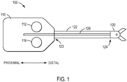
- Surgical instrument 100 may include a force transmission mechanism 110, a shaft 122 connected to force transmission mechanism 110 at a proximal end 123 of shaft 122, and an end effector 120 connected to a distal end 124 of shaft 122.
- Shaft 122 may be flexible.
- shaft 122 may have a diameter ranging from about 3 mm to about 15 mm.
- the diameter of shaft 122 may range, for example, from about 5 mm to about 8 mm.
- Surgical instrument 100 may include one or more members to translate force between force transmission mechanism 110 and end effector 120.
- one or more drive element(s) 126 may connect force transmission mechanism 110 to end effector 120 to provide actuation forces to end effector 120, such as by extending through an interior of shaft 122.
- force transmission mechanism 110 may actuate end effector 120 to, for example, control a wrist mechanism (not shown in FIG. 1 ) of instrument 100 and/or to control a jaw of end effector 120 (or other moveable part).
- end effector 120 may be fixed to shaft 122, force translated from force translation mechanism 110 to end effector 120 may in turn be translated to shaft 122, such as when force translation mechanism 110 actuates end effector 120 in a rolling motion.
- Drive element(s) 126 may be in the form of tension elements, such as when force transmission mechanism 110 is a pull-pull mechanism, or one or more drive element rods or push rods, such as when force transmission mechanism 110 is a push-pull mechanism, as described in U.S. Patent No. 8,545,515 .
- Force transmission mechanism 110 may include one or more components to engage with a patient side cart of a teleoperated surgical system to translate a force provided by patient side cart to surgical instrument 100.
- force transmission mechanism 110 may include one or more interface disks 112, 114 that engage with a manipulator of a patient side cart, as described in U.S. Patent No. 8,545,515 .
- interface disks 112, 114 utilize actuation forces from a manipulator to actuate instrument 100.
- first disk 112 may be configured to provide a rolling motion to shaft 122 and provide a roll DOF for end effector 120, while second disk 114 may operate a jaw mechanism of end effector 120 to open and close.
- the force transmission mechanism may include other interface disks that actuate various other functionalities of a surgical instrument, as those having ordinary skill in the art are familiar with.
- an exemplary surgical instrument 200 for a teleoperated surgical system includes a shaft 202, clevis 204, and an end effector 206.
- surgical instrument 200 may include a wrist that couples the clevis 204 to the shaft 202, or surgical instrument 200 may be a non-wristed instrument. If surgical instrument 200 lacks a wrist, end effector 206 may be directly connected to clevis 204 and clevis 204 may be directly connected to shaft 202.
- end effector 206 may include a first jaw 220 and a second jaw 230.
- First jaw 220 may include a grip portion 222, a connection aperture 224, and an actuation aperture 226.
- second jaw 230 may include a grip portion 232, a connection aperture 234, and an actuation aperture 236.
- connection apertures 224, 234 may be used to connect jaws 220, 230 to clevis 304, which is in turn connected to shaft 202.
- a rivet or pin 208 may be inserted through connection apertures 224, 234 and through an aperture 205 in clevis 204 to connect jaws 220, 230 to clevis 204.
- Pin 208 may also serve as an axis of rotation about which jaws 220, 230 rotate when end effector 206 is actuated to open and close jaws 220, 230, which will be described below.
- Surgical instrument 200 may include a mechanism to actuate end effector 206, such as to open and close jaws 220, 230.
- surgical instrument may include a drive element 210 connected to end effector 206.
- a proximal end (not shown) of drive element 210 may be connected to a manipulator (not shown) of a teleoperated surgical system that provides motive force to drive element 210.
- drive element 210 may be a push/pull drive element rod that is pushed or pulled along direction 213 in FIG. 3 by a motive force provided by the manipulator to actuate end effector 206.
- a distal end 215 of drive element 210 may be connected to end effector 206 to translate the motive force from the manipulator to the jaws 220, 230.
- distal end 215 of drive element 210 may include a first projection 212 connected to jaw 220 and a second projection 214 connected to jaw 230.
- jaw 220 may include an actuation aperture 226 that first projection 212 is inserted into and jaw 230 may include an actuation aperture 236 that second projection 214 is inserted into.
- Actuation apertures 226, 236 may be in form of, for example, elongated slots, such as rectangular or oval slots that projections 212, 214 may be inserted into.
- projections 212, 214 may slide within actuation apertures 226, 236, causing jaws 220, 230 to pivot about pin 208.
- FIG. 4 a side view of end effector 206 is shown along line 4-4 in FIG. 2 but without clevis 204 and pin 208.
- the jaws 220, 230 of end effector 206 are in a closed state.
- drive element 210 is not shown in FIG. 4
- second projection 214 is shown within actuation slot 236 of jaw 230.
- drive element 210 is pushed in direction 217 in FIG. 4
- second projection 214 is forced upwards. Consequently, jaws 220, 230 rotate and pivot about pin (not shown) located in connection aperture 234 in direction 219 in FIG. 5 , causing jaws 220, 230 to separate and open.
- Surgical instrument 200 may include one or more features to assist with the movement of drive element 210 during actuation of end effector 206, such as between the closed and open states shown in the example of FIGS. 4 and 5 , respectively.
- clevis 204 may include one or more features to assist with the movement of drive element 210.
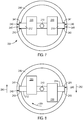
- FIG. 6 a cut away view of an exemplary clevis 204 is provided.
- Clevis 204 includes a sidewall 246 that forms an outer surface of clevis 246 and in FIG. 6 a portion of sidewall 246 has been removed to show internal features of clevis 204.
- Clevis 204 may include a lumen 244 for passage of drive element 210 through clevis 204 and an aperture 205 for a pin 208 to connect jaws 220, 230 of an end effector 206, as discussed above in regard to the example of FIG. 3 .
- clevis 204 may include other lumens for other components, such as, for example, conduits to provide energy to end effector 206 (e.g., electrical wires) and/or additional actuation components (e.g., an actuation element for an additional degree of freedom for surgical instrument or for a component, such as a knife).
- clevis 204 may include one or more features to interact with the projections 212, 214 of drive element 210.
- clevis 204 may include a groove 240 in the sidewall 246, as shown in the example of FIG. 6 .
- groove 240 may have a finite depth and a bottom surface 245, as shown in FIG. 6 .
- the configuration of groove 240 is not limited to such a geometry and groove 240 may instead be provided as a slot (not shown) that passes completely through sidewall 246 of clevis 204.
- One or more projections 212, 214 of drive element 210 may be configured to extend into groove 240 so that when drive element 210 is moved to actuate end effector 206, groove 240 supports a projection 212, 214.
- one or more projections 212, 214 of drive element 210 may have a length sufficient to extend through jaws 220, 230 (such as through actuation apertures 226, 236) and into groove 240 in sidewall 246.
- FIG. 7 a cross-section view is shown along line 7-7 of FIG. 4 is shown but with clevis 204 also provided.
- FIG. 8 depicts a cross-sectional view along line 8-8 of FIG. 5 but with clevis also provided.
- clevis 204 may include two grooves 240; one for each projection 212, 214 of drive element 210.
- grooves 240 may be opposed to one another, as shown in FIG. 7 . Because projections 212, 214 of drive element 210 are placed within grooves 240, when drive element 210 is moved to actuate an end effector 206 (e.g., by moving drive element 210 in and out of the page of FIG.
- grooves 240 support and/or guide the movement of projections 212, 214 and thus drive element 210.
- at least one of sidewalls 241, 243 of groove 240 may contact projections 212, 214 as drive element 210 is moved and projections 212, 214 slide back and forth within groove 240.
- a bottom surface 245 of groove 240 may be in contact with projections 212, 214 to support projections 212, 214, either alternatively or in addition to contact with one or more sidewalls 241, 243.
- FIG. 9 a cut-away view of an exemplary clevis 204 is shown, which is similar to the view of FIG. 6 , except that the end of projection 212 is shown within groove 240.
- projection 212 may contact sidewalls 241, 243 of groove 240, such as at contact portions 248, so that projection 212 is supported by groove 240.
- contact portions 248 may be characterized by contact between a circle and a planar surface.
- contact portions 248 may be a substantially tangential contact portion between projections 212, 214 and sidewalls 214, 243 of groove 240.
- contact portions 248 may have a shape of line or a point.
- FIGS. 7 and 8 When drive element 210 is moved to actuate an end effector 206 to open and close jaws 220, 230, portions of jaws 220, 230 may move apart from one another. This is also demonstrated in FIGS. 7 and 8 .
- jaws 220, 230 are in a closed position, as shown in the example of FIG. 4 .
- FIG. 8 jaws 220, 230 have been moved to an open position due to the movement of drive element 210, as shown in the example of FIG. 5 .
- the proximal ends of jaws 220, 230 may move in different directions when jaws 220, 230 move to an open position, as shown in the example of FIG. 5 .
- FIG. 8 shows that the end of jaw 220 has moved in direction 250 relative to FIG. 7 and that the end of jaw 230 has moved in direction 252 relative to FIG. 7 .
- Torque in direction 254 causes drive element 210 to twist, resulting in projection 212 exerting force against sidewall 243 of one groove 240 and projection 214 exerting force against sidewall 241 of another groove 240.
- the force exerted between projections 212, 214 and sidewalls 241, 243 is limited to small areas.
- grooves 240 may permanently deform and/or wear as projections 212, 214 slide back and forth within grooves 240 and press against sidewalls 241, 243.
- jaws 220, 230 may move in opposite directions to directions 250, 252 shown in the example of FIG. 8 when jaws 220, 230 are actuated to a closed position, which may result in a torque and twisting motion in a direction opposite to direction 254 in FIG. 8 .
- clevis 204 may be made from a non-metallic material.
- clevis 204 may be made of a plastic, such as, for example polyether ether ketone (PEEK), including glass filled PEEK.
- PEEK polyether ether ketone
- clevis 204 is made of a non-metallic material, for example, a plastic material, permanent deformation and/or wear may occur on the surfaces of grooves 240, such as sidewalls 241, 243.
- forces between projections 212, 214 and sidewalls 241, 241 may even be sufficient for projections to pop out of grooves 240 when drive element 210 is twisted in direction 254, particularly when sidewalls 241, 243 have become worn.
- a surgical instrument with enhanced durability.
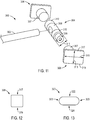
- Push/pull drive element 300 may be, for example, a push rod, a wire, a cable, or other structure known by one of ordinary skill in the art for use as a push/pull drive element.
- push/pull drive element may be an element with sufficient columnar compressibility to transmit an axial pushing force applied to the push/pull drive element.
- Push/pull drive element 300 may be used according to the same functions as drive element 210 described above for the examples of FIGS. 2-9 .
- push/pull drive element 300 may include a shaft 302 connected to a head 304.
- Head 304 may include, for example, a cross shaft 309 and end portions 306, as shown in FIG. 11 .
- Cross shaft 309 may also be referred to, for example, as a main portion of head 304.
- Head 304 may be formed from separate pieces, such as cross shaft 309 and end portions 306, as shown in the examples of FIGS. 10 and 11 , or head 304 may be provided with a single piece construction by providing cross shaft 309 and end portions 306 as a single piece.
- portions of push/pull drive element 300 such as shaft 302 and cross shaft 309 and end portions 306, may be made of a metal.
- portions of push/pull drive element 300 may be made of a wear resistant stainless steel alloy, such as Nitronic® 60.
- push/pull drive element 300 may include an insulative material 308, such as when push/pull drive element 300 is used in a surgical instrument is energized, as will be discussed below.
- Insulative material 308 may be a material that minimizes arcing and electrical conductivity, such as, for example, a plastic material.
- insulative material 308 may be provided on at least a portion of cross shaft 309 and shaft 302.
- insulative material 308 may be provided on at least one of cross shaft 309 and shaft 302 by overmolding the insulative material 308.
- cross shaft 309 includes engagement portions 310 that engage with portions of an end effector when push/pull drive element 300 is moved to actuate the end effector.
- engagement portions 310 may be configured to engage actuation apertures 226, 236 of jaws 220, 230 of end effector 206, as described above in the examples of FIGS. 2-5 , to actuate end effector 206 when push/pull drive element 300 is moved.
- engagement portions 310 may have a circular cross-section, like projections 212, 214 of the examples of FIGS. 2-8 .
- engagement portions 310 of cross shaft 309 may have a diameter 311 (see FIG.
- diameter 311 of engagement portions 310 need not be substantially the same diameter 247 of projections 212, 214, but instead may be different. For instance, the diameter 311 of engagement portions 310 may be smaller than the diameter 247 of projections 212, 214.
- engagement portions 310 may have a non-circular cross-section.
- a cross-sectional shape of engagement portions 310 may include one or more flat surface portions (not shown).
- One or more flat surface portions may be provided to increase the contact area between engagement portions 310 and actuation apertures 226, 236 of jaws 220, 230, such as to increase the distribution of forces exerted between engagement portions 310 and jaws 220, 230.
- actuation apertures 226, 236 of jaws 220, 230 may have a different shape than the shape shown in the example of FIGS. 2 and 3 .
- actuation apertures 226, 236 may be curved, instead of being straight as shown in FIGS. 2 and 3 .
- actuation apertures 226, 236 may be curved so that actuation apertures 226, 236 are either convex or concave in shape relative to connection apertures 224, 234 in the example of FIG. 3 .
- End portions 306 of push/pull drive element 300 may be configured to enhance the distribution of forces between end portions 306 and other components of a surgical instrument, such as a clevis. As shown in the example of FIGS. 10 and 11 , end portions 306 may be larger than engagement portions 310 of cross shaft 309. For instance, engagement portions 310 may have a diameter or width 311, while end portions 306 may have a width 313 or 315 that is larger than the width 311 of engagement portions 310. If dimensions 313, 315 of end portions 306 are not equal or substantially equal, the width of end portions 306 may be the larger of dimensions 313, 315, according to an example.
- dimension 315 of end portion 306 is larger than dimension 313, dimension 315 is the width of end portions and is also larger than the width 311 of engagement portions 310.
- a ratio of dimension 315 to diameter 311 is greater than 1.
- a ratio of dimension 315 to diameter 311 ranges from, for example, about 1.1 to about 1.3.
- dimension 315 may have a length of, for example, about 1.9 mm (0.075 inches) while diameter 311 is, for example, about 1.55 mm (0.061 inches).
- End portions 306 of push/pull drive element 300 may have a cross-section with various shapes. As shown in the example of FIGS. 10 and 11 , end portions 306 may have a rectangular shape. As shown in the example of FIG. 12 , end portions 306 may have a square shape. According to another example, an end portion 320 may have an oval shape, as shown in FIG. 13 . The oval shape may include flat surfaces 322, 324 and rounded ends 323, as shown in the example of FIG. 13 . However, the cross-sectional shape of end portions of a push/pull drive element is not limited to the examples of FIGS. 10-13 and other shapes may be utilized.
- a cross-sectional shape of an end portion of a push/pull drive element includes one or more flat surface portions.
- end portions 306 may include flat surface portions 317, 319.
- an end portion 320 having an oval shape or other non-rectangular or non-square shape may have flat surface portions 322, 324, as shown in the example of FIG. 13 .
- flat surface portions may be opposite to one another and substantially in planes that are parallel to the elongated direction of the groove 240 of the clevis, as shown in the examples of FIGS. 11-13 .
- end portions 306 By providing end portions 306 with a cross-section that is enlarged relative to that of the cross shaft 309, providing end portions 306 having a shape described above, and/or providing end portions 306 having at least one flat surface portion in a plane parallel to the elongated direction of the groove 240 of the clevis, a contact area between end portions 306 and a clevis of a surgical instrument may be increased. This in turn may enhance the distribution of forces between end portions 306 and the clevis.
- a cut away view of a clevis 330 is provided to show internal features of clevis 330, including groove 340 formed in a sidewall 336 of clevis 330.
- Clevis 330 may further include an aperture 335 for a pin (not shown) to connect the jaws of an end effector and groove 340 may include sidewalls 341, 343.
- an end portion 306 of a push/pull drive element 300 may be placed within groove 340 so that groove 340 supports and/or guides end portion 306 as push/pull drive element 300 moves back and forth to actuate an end effector.
- the one or more surface portions of end portion 306 may be in contact with one or more surfaces of groove 340.
- FIG. 15 which is side view of clevis 340 and push/pull drive element 300, with an end portion 306 of push/pull drive element 300 located within groove 340, surface portions 317, 319 of end portion 306 may engage one or both of sidewalls 341, 343 of groove 340 via contact portions 350.
- surface portions 317, 319 may be flat. Because end portion 306 has one or more surface portions 317, 319, contact portions 350 between end portion 306 and sidewalls 341, 343 of groove 340 are not limited to point contacts or approximately tangential contacts, as discussed above in regard to the example of FIG. 9 , but instead provide relatively large contact areas over which the forces exerted between end portion 306 and groove 340 may be distributed.
- end portions 306 of push/pull drive element 300 have enhanced resistance to the forces exerted when push/pull drive element 300 actuates an end effector and is subjected to twisting, as described above in regard to the example of FIGS. 7 and 8 .
- push/pull drive element 300 may include an insulative material 308, particularly when push/pull drive element 300 is used in an energized surgical instrument.
- the examples described herein are not limited to energized surgical instruments and a push/pull drive element may be used in a non-energized surgical instrument.
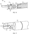
- FIG. 16 a cut-away view of a non-energized surgical instrument 400 is shown.
- Surgical instrument 400 may include a shaft 402, clevis 404, end effector 406, and a push/pull drive element 410.
- End effector 406 may include jaws 420, 430 that may be connected to clevis 404 by a pin 408 inserted through an aperture 405.
- Push/pull drive element 410 may be configured according to the examples of FIGS. 10-15 except that push/pull drive element 410 does not include insulative material 308 because surgical instrument 400 is not energized.
- push/pull drive element 410 may include a shaft 412, one or more engagement portions 414 (such as, for example, engagement portions 414 provided by a cross shaft, as discussed above in regard to FIG. 11 ), and one or more end portions 416.
- End portion 416 may be inserted within a groove 440 of clevis 404, as discussed above in regard to the examples of FIGS. 10-15 , so that end portion 416 is guided and/or supported when push/pull drive element 410 moves back and forth to actuate end effector 406.
- end portions of a push/pull drive element Due to the shape and size of end portions of a push/pull drive element as described in the examples of FIGS. 10-17 , the amount of contact area between the end portions and a clevis groove is significantly increased.
- the end portions may advantageously enhance the distribution of force exerted between the end portions and grooves of a clevis.
- end portions of a push/pull drive element may counteract torque and a twisting motion applied to the push/pull drive element during actuation of an end effector, which may otherwise lead to deformation or wear of the clevis groove or the push/pull drive element popping out of the clevis groove.
- end portions of a push/pull drive element may minimize or reduce permanent deformation or wear of a groove of a clevis made of a non-metallic material, such as a plastic.
- an electrical connection is provided between an end effector of the surgical instrument and one or more conduits providing electrical energy to the end effector.
- an end effector of the surgical instrument When a surgical instrument is energized, an electrical connection is provided between an end effector of the surgical instrument and one or more conduits providing electrical energy to the end effector.
- providing and maintaining a connection between the one or more conduits and the end effector may be difficult.
- the level of difficultly of providing a connection that is functional and durable is relatively high.
- an outer diameter of a surgical instrument may be, for example, approximately 5 mm.
- FIG. 18 an exemplary embodiment of a surgical instrument 500, according to the present invention, is shown that includes jaws 502, 504 connected via a pin 508, a clevis 506, and a push/pull drive element 510.
- Push/pull drive element 510 may be configured according to the examples of FIGS. 10-17 .
- surgical instrument 500 further includes a connector assembly 530 to connect one or more conduits 520, 522 to jaws 502, 504. Conduits 520, 522 may provide energy to jaws 502, 504, such as, for example electrical energy, to energize jaws 502, 504.
- FIG. 19 shows surgical instrument 500 with jaw 504 removed so that components of surgical instrument 500 may be more easily viewed, such as connector assembly 530.
- Surgical instrument 500 may further include a shaft (not shown) connected to clevis 506 and covering conduits 520, 522.
- jaws 502, 504 When jaws 502, 504 are actuated, jaws 502, 504 move relative to other components of surgical instrument 500. For instance, jaws 502, 504 may pivot in direction 540 relative to pin 508, as shown in the exemplary embodiments of FIGS. 18 and 19 . Due to the movement of jaws 502, 504, providing a connection between conduits 520, 522 and jaws 502, 504 can be challenging. For instance, if conduits 520, 522 are directly connected to jaws 502, 504, at least a portion of conduits 520, 522 may move when jaws 502, 504 move, which may lead to challenges in providing a durable connection between jaws 502, 504 and conduits.
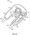
- FIG. 20 an exemplary embodiment of a connector assembly 530 is shown, which includes a body 531.
- Connector assembly 530 provides a connection between one or more conduits 520, 522 and an end effector, such as jaws 502, 504, so that energy (e.g., electrical energy) may be provided from the one or more conduits 520, 522 to the end effector.
- energy e.g., electrical energy
- connector assembly 530 provides an electrical connection between one or more conduits 520, 522 and an end effector in this exemplary embodiment.
- body 531 is made of an electrically insulative material.
- body 531 may be made of a plastic, such as, for example, a polyphthalamide (PPA) (e.g., Amodel®, which is sold by Solvay Advanced Polymers, L.L.C.).
- PPA polyphthalamide
- Body 531 may be used, for instance, to provide a structural support for a connection between one or more conduits 520, 522 and jaws 502, 504 while substantially insulating components of surgical instrument 500 from the energy connected between the one or more conduits 520, 522 and jaws 502, 504.
- body 531 is approximately U-shaped and may include a first leg 532 and a second leg 534.
- legs 532, 534 may be separated by a gap 536, as shown in the exemplary embodiment of FIG. 20 .
- Gap 536 may, for example, provide space for movement of push/pull drive element 510 within body 531, as shown in the exemplary embodiment of FIG. 19 , such as when push/pull drive element 510 is moved to actuate jaws 502, 504.
- Body 531 further includes a lumen 538 that pin 508 may be inserted through, as shown in the exemplary embodiment of FIGS. 18 and 19 .
- legs 532, 534 of body include a structure to receive conduits 520, 522.
- leg 534 includes a cavity 533 to receive conduit 520, as shown in the exemplary embodiment of FIG. 20 .
- Cavity 533 may be open, as shown in the exemplary embodiment of FIG. 20 , or cavity may be at least partially covered.
- Conduit 520 may be received in cavity 533 by, for example, inserting conduit 520 through an aperture 535 in leg 534.
- Leg 532 may be configured according to any of the above exemplary embodiments discussed for leg 534.
- connector assembly 530 further includes one or more connector portions 550.
- connector assembly 530 may include a connector portion 550 for each conduit.
- connector assembly 530 may include a connector portion 550 for each of conduits 520, 522, as shown in FIG. 21 .
- Connector portions 550 may be attached to body 531.
- connector portions 550 may be fit over protuberances 537.
- Connector portions 550 may have a shape corresponding to the shape of protuberances 537.
- connector portions 550 may be press fit to protuberances 537, according to an exemplary embodiment.
- protuberances 537 may connect to clevis 506 to attach connector assembly 530 and clevis 506.
- Connector portions 550 may include one or more structures to attach a conduit.
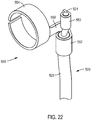
- FIG. 22 which depicts an exemplary embodiment of conduit 520 attached to connector portion 550
- connector portion 550 may include a first attachment 553 and a second attachment 552.
- the second attachment 552 connects connector portion 550 to conduit 520.
- conduit 520 includes more than one component, such as an outer insulative cover 523 and a conductor 521, as shown in the exemplary embodiment of FIG. 22
- second attachment 552 may connect to insulative cover 523 while first attachment 553 connects to an exposed portion of conductor 521.
- second attachment 552 may be provided, for example, to assist with maintaining a position of conductor 520 relative to connector portion 550, while first attachment 553 is provided to form an electrically conductive contact between connector portion 550 and conduit 520, particularly conductor 521.
- Attachments 552, 553 may be attached to conduit 520 via a mechanical connection, such as, for example, crimping attachments 552, 553 to conduit 520, via a bond, such as solder (e.g., soldering attachment 553 to conductor 521), or other joining method known to one of ordinary skill in the art.
- Conduit 522 may be connected to connector portion 550 in the same way, according to an exemplary embodiment.
- Connector portions 550 may further include one or more structures to contact a portion of an end effector.
- connector portions 550 may include a contact portion 554 to contact at least one of jaws 502, 504.
- Contact portion 554 may contact at least one of jaws 502, 504 via sliding contact, according to an exemplary embodiment.
- jaw 504 may include an aperture 505 so that jaw 504 may be fit over contact portion 554.
- aperture 505 may be structured to have a shape and size corresponding to contact portion 554 so that the portion of jaw 504 forming aperture 505 is in contact with contact portion 554.
- contact portions 554 may have a split ring shape, as shown in the exemplary embodiments of FIGS.
- jaw 504 moves, such as by pivoting in direction 540 relative to pin 508, jaw 504 remains in contact with contact portion 554.
- Jaw 502 may be configured according to the exemplary embodiments of jaw 504 to also form a sliding contact with a contact portion 554 of a connector assembly 530.
- a connection such as an electrical connection, may be provided between conduits 520, 522 and jaws 502, 504 that is advantageously durable while permitting movement of jaws 502, 504 and providing energy to jaws 502, 504 from conduits 502, 504.
- connectors 530 may be configured so that jaws 502, 504 move independently of contact portions 554. For instance, when jaws 502, 504 move, such as when jaws 502, 504 are actuated to pivot in direction 540 about pin 508, as shown in the exemplary embodiment of FIGS. 18 and 19 , contact portion 554 remains substantially stationary as jaw 504 slides over contact portion 554. As a result, conduits 520, 522 connected to connectors 530 may also remain substantially stationary as jaws 502, 504, which may advantageously minimize or reduce wear or deformation of conduits 520, 522 and connections between conduits 520, 522 and connectors 530. Further, conduits 520, 522 are not directly connected to jaws 502, 504 because connectors 530 form connections between conduits 520, 522 and jaws 502, 504.
- a contact portion 554 may be connected to the one or more attachment(s) 552, 553 of connector portions 550 by a bridge 556, as shown in the exemplary embodiment of FIG. 22 .
- connector portions 550 may have a single piece construction.
- the one or more attachment(s) 552, 553, contact portion 554, and bridge 556 may be formed from a single piece, although the exemplary embodiments of connector portions 550 described herein are not limited to a single piece construction.
- connection portions 550 may be made of a conductive material, such as an electrically conductive material, so that energy provided by conduits 520, 522 may be provided to jaws 502, 504 via connector portions 550.
- connection portions 550 may be made of a metal, such as, for example, a stainless steel.
- a connection may be advantageously provided between the push/pull drive element and a component of the surgical instrument that has enhanced durability while permitting push/pull drive element to move and actuate an end effector of the surgical instrument.
- a connection may be advantageously provided between one or more conduits and the end effector that is durable, while permitting movement of the end effector and providing energy to the end effector from the one or more conduit(s).
Landscapes
- Health & Medical Sciences (AREA)
- Life Sciences & Earth Sciences (AREA)
- Surgery (AREA)
- Engineering & Computer Science (AREA)
- Animal Behavior & Ethology (AREA)
- General Health & Medical Sciences (AREA)
- Biomedical Technology (AREA)
- Heart & Thoracic Surgery (AREA)
- Medical Informatics (AREA)
- Molecular Biology (AREA)
- Veterinary Medicine (AREA)
- Nuclear Medicine, Radiotherapy & Molecular Imaging (AREA)
- Public Health (AREA)
- Robotics (AREA)
- Physics & Mathematics (AREA)
- Plasma & Fusion (AREA)
- Otolaryngology (AREA)
- Ophthalmology & Optometry (AREA)
- Surgical Instruments (AREA)
- Manipulator (AREA)
Applications Claiming Priority (3)
| Application Number | Priority Date | Filing Date | Title |
|---|---|---|---|
| US201361803046P | 2013-03-18 | 2013-03-18 | |
| PCT/US2014/026137 WO2014151633A1 (en) | 2013-03-18 | 2014-03-13 | Surgical instrument drive element, and related devices, systems, and methods |
| EP14768826.1A EP2976026B1 (en) | 2013-03-18 | 2014-03-13 | Surgical instrument drive element, related devices and systems |
Related Parent Applications (2)
| Application Number | Title | Priority Date | Filing Date |
|---|---|---|---|
| EP14768826.1A Division EP2976026B1 (en) | 2013-03-18 | 2014-03-13 | Surgical instrument drive element, related devices and systems |
| EP14768826.1A Division-Into EP2976026B1 (en) | 2013-03-18 | 2014-03-13 | Surgical instrument drive element, related devices and systems |
Publications (2)
| Publication Number | Publication Date |
|---|---|
| EP3488807A1 EP3488807A1 (en) | 2019-05-29 |
| EP3488807B1 true EP3488807B1 (en) | 2020-09-09 |
Family
ID=51531098
Family Applications (2)
| Application Number | Title | Priority Date | Filing Date |
|---|---|---|---|
| EP19151045.2A Active EP3488807B1 (en) | 2013-03-18 | 2014-03-13 | Surgical instrument drive element, related devices and systems |
| EP14768826.1A Active EP2976026B1 (en) | 2013-03-18 | 2014-03-13 | Surgical instrument drive element, related devices and systems |
Family Applications After (1)
| Application Number | Title | Priority Date | Filing Date |
|---|---|---|---|
| EP14768826.1A Active EP2976026B1 (en) | 2013-03-18 | 2014-03-13 | Surgical instrument drive element, related devices and systems |
Country Status (6)
| Country | Link |
|---|---|
| US (4) | US9498242B2 (enExample) |
| EP (2) | EP3488807B1 (enExample) |
| JP (4) | JP6383780B2 (enExample) |
| KR (1) | KR102256358B1 (enExample) |
| CN (4) | CN113331951B (enExample) |
| WO (1) | WO2014151633A1 (enExample) |
Families Citing this family (33)
| Publication number | Priority date | Publication date | Assignee | Title |
|---|---|---|---|---|
| EP3488807B1 (en) | 2013-03-18 | 2020-09-09 | Intuitive Surgical Operations Inc. | Surgical instrument drive element, related devices and systems |
| ITUB20154977A1 (it) | 2015-10-16 | 2017-04-16 | Medical Microinstruments S R L | Strumento medicale e metodo di fabbricazione di detto strumento medicale |
| CN108289691B (zh) * | 2015-11-13 | 2021-04-09 | 直观外科手术操作公司 | 具有二自由度腕部的推拉式缝合器 |
| US10973517B2 (en) | 2015-11-13 | 2021-04-13 | Intuitive Surgical Operations, Inc. | Stapler with composite cardan and screw drive |
| NL2017630B1 (en) * | 2016-10-17 | 2018-04-24 | Surge On Medical B V | A surgical device |
| US11364067B2 (en) * | 2017-10-06 | 2022-06-21 | Cilag Gmbh International | Electrical isolation of electrosurgical instruments |
| EP3727140B1 (en) | 2017-12-22 | 2023-11-01 | Briteseed, LLC | A compact system used to determine tissue or artifact characteristics |
| EP3578118B1 (de) | 2018-06-05 | 2022-08-31 | Erbe Elektromedizin GmbH | Chirurgisches instrument |
| KR20210032998A (ko) * | 2018-07-17 | 2021-03-25 | 인튜어티브 서지컬 오퍼레이션즈 인코포레이티드 | 감소된 커패시턴스를 갖는 수술 기구, 관련 디바이스, 및 관련 방법 |
| USD904611S1 (en) | 2018-10-10 | 2020-12-08 | Bolder Surgical, Llc | Jaw design for a surgical instrument |
| JP7066875B2 (ja) * | 2018-11-30 | 2022-05-13 | オリンパス株式会社 | 把持機構 |
| WO2020131685A1 (en) | 2018-12-21 | 2020-06-25 | Intuitive Surgical Operations, Inc. | Surgical instruments with switches for deactivating and/or identifying stapler cartridges |
| CN113194847A (zh) * | 2018-12-21 | 2021-07-30 | 直观外科手术操作公司 | 用于外科手术器械的致动机构 |
| WO2020214258A1 (en) | 2019-04-15 | 2020-10-22 | Intuitive Surgical Operations, Inc. | Staple cartridge for a surgical instrument |
| EP3975875B1 (en) | 2019-05-31 | 2025-09-24 | Intuitive Surgical Operations, Inc. | Staple cartridge for a surgical instrument |
| CA3165884A1 (en) * | 2019-12-30 | 2021-07-08 | Beijing Surgerii Technology Co., Ltd. | Surgical effector, surgical tool and surgical robot |
| WO2021141971A1 (en) | 2020-01-07 | 2021-07-15 | Intuitive Surgical Operations, Inc. | Surgical instruments for applying multiple clips |
| WO2022150212A1 (en) | 2021-01-08 | 2022-07-14 | Intuitive Surgical Operations, Inc. | Surgical instrument with linear and purse string suture staples |
| DE102021201311A1 (de) * | 2021-02-11 | 2022-08-11 | Aesculap Ag | Chirurgisches Instrument, Werkzeugeinrichtung für ein solches chirurgisches Instrument und Verfahren zur Herstellung einer solchen Werkzeugeinrichtung |
| US12433664B2 (en) | 2021-05-03 | 2025-10-07 | Covidien Lp | Motor position control and methods for robotic assisted sealing instrument |
| US12257014B2 (en) * | 2021-06-22 | 2025-03-25 | Intuitive Surgical Operations, Inc. | Devices and methods for crimp interface for cable tension sensor |
| US12065076B2 (en) * | 2021-06-28 | 2024-08-20 | Dana Automotive Systems Group, Llc | High efficiency electrical conduit |
| GB2611346B (en) * | 2021-10-01 | 2024-08-07 | Cmr Surgical Ltd | A robotic surgical instrument |
| WO2023101968A1 (en) | 2021-11-30 | 2023-06-08 | Endoquest Robotics, Inc. | Steerable overtube assemblies for robotic surgical systems |
| KR20240153547A (ko) | 2021-11-30 | 2024-10-23 | 엔도퀘스트 로보틱스 인코포레이티드 | 로봇 수술 시스템용 배리어 드레이프 어댑터 |
| TWI838986B (zh) | 2021-11-30 | 2024-04-11 | 美商安督奎斯特機器人公司 | 患者控制台、具有該患者控制台的機器人手術系統及其執行方法 |
| KR20240134850A (ko) | 2021-11-30 | 2024-09-10 | 엔도퀘스트 로보틱스 인코포레이티드 | 로봇 수술 시스템용 마스터 제어 시스템 |
| WO2023101974A1 (en) | 2021-11-30 | 2023-06-08 | Endoquest Robotics, Inc. | Force transmission systems for robotically controlled medical devices |
| KR20240144086A (ko) | 2021-11-30 | 2024-10-02 | 엔도퀘스트 로보틱스 인코포레이티드 | 일회용 엔드 이펙터 |
| IT202300012834A1 (it) | 2023-06-21 | 2024-12-21 | Medical Microinstruments Inc | Strumento attivo elettrochirurgico e cuffia di protezione, particolarmente per teleoperazione medico-chirurgica, e relativo sistema robotizzato |
| IT202300017115A1 (it) | 2023-08-10 | 2025-02-10 | Medical Microinstruments Inc | Strumento elettrochirurgico bipolare per teleoperazione medico-chirurgica e metodo di fabbricazione |
| IT202300025815A1 (it) | 2023-12-04 | 2025-06-04 | Medical Microinstruments Inc | Strumento chirurgico o microchirurgico per teleoperazione robotizzata comprendente un manicotto flessibile munito di almeno una pista elettricamente conduttiva |
| CN119632663B (zh) * | 2025-02-14 | 2025-12-02 | 温州医科大学附属第一医院 | 手术执行器、手术工具及手术机器人 |
Family Cites Families (32)
| Publication number | Priority date | Publication date | Assignee | Title |
|---|---|---|---|---|
| JPS60107291U (ja) * | 1983-12-27 | 1985-07-22 | 株式会社 ニチベイ | ロ−ルスクリ−ン |
| US5396900A (en) | 1991-04-04 | 1995-03-14 | Symbiosis Corporation | Endoscopic end effectors constructed from a combination of conductive and non-conductive materials and useful for selective endoscopic cautery |
| WO1994024947A1 (en) * | 1993-04-30 | 1994-11-10 | Minnesota Mining And Manufacturing Company | Surgical instrument having an articulated jaw structure and a detachable knife |
| US5395369A (en) * | 1993-06-10 | 1995-03-07 | Symbiosis Corporation | Endoscopic bipolar electrocautery instruments |
| US5782749A (en) * | 1994-05-10 | 1998-07-21 | Riza; Erol D. | Laparoscopic surgical instrument with adjustable grip |
| CA2194775A1 (en) * | 1994-07-14 | 1996-02-01 | Symbiosis Corporation | Track guided end effector assembly |
| US5478350A (en) * | 1994-07-14 | 1995-12-26 | Symbiosis Corporation | Rack and pinion actuator handle for endoscopic instruments |
| US5695511A (en) * | 1994-11-29 | 1997-12-09 | Metamorphic Surgical Devices | Surgical instruments for minimally invasive procedures |
| US5904702A (en) * | 1997-08-14 | 1999-05-18 | University Of Massachusetts | Instrument for thoracic surgical procedures |
| US6139563A (en) | 1997-09-25 | 2000-10-31 | Allegiance Corporation | Surgical device with malleable shaft |
| US5919206A (en) * | 1998-02-20 | 1999-07-06 | C. M. Wright, Inc. | Surgical tool |
| US6193718B1 (en) * | 1998-06-10 | 2001-02-27 | Scimed Life Systems, Inc. | Endoscopic electrocautery instrument |
| US20040249374A1 (en) * | 1998-10-23 | 2004-12-09 | Tetzlaff Philip M. | Vessel sealing instrument |
| CA2442960C (en) * | 2001-04-06 | 2011-03-22 | Sherwood Services Ag | Vessel sealing instrument |
| US6733514B2 (en) | 2001-10-05 | 2004-05-11 | Pilling Weck Incorporated | Jaw assembly for endoscopic instruments |
| DE202004010780U1 (de) * | 2004-07-02 | 2004-09-09 | Karl Storz Gmbh & Co. Kg | Medizinisches Instrument für die Elektrochirurgie |
| US7918848B2 (en) * | 2005-03-25 | 2011-04-05 | Maquet Cardiovascular, Llc | Tissue welding and cutting apparatus and method |
| US8197472B2 (en) * | 2005-03-25 | 2012-06-12 | Maquet Cardiovascular, Llc | Tissue welding and cutting apparatus and method |
| US8771270B2 (en) | 2008-07-16 | 2014-07-08 | Intuitive Surgical Operations, Inc. | Bipolar cautery instrument |
| US8968355B2 (en) * | 2008-08-04 | 2015-03-03 | Covidien Lp | Articulating surgical device |
| US8409200B2 (en) * | 2008-09-03 | 2013-04-02 | Ethicon Endo-Surgery, Inc. | Surgical grasping device |
| CN102264307A (zh) * | 2008-12-12 | 2011-11-30 | 伊顿株式会社 | 手术器械 |
| US8333780B1 (en) * | 2009-06-05 | 2012-12-18 | Okay Industries, Inc. | Surgical tool and method of operation |
| JP4841705B2 (ja) * | 2009-09-15 | 2011-12-21 | オリンパスメディカルシステムズ株式会社 | 内視鏡用処置具 |
| US8545515B2 (en) | 2009-09-23 | 2013-10-01 | Intuitive Surgical Operations, Inc. | Curved cannula surgical system |
| US9339341B2 (en) | 2010-02-08 | 2016-05-17 | Intuitive Surgical Operations, Inc. | Direct pull surgical gripper |
| RO126740A2 (ro) * | 2010-04-02 | 2011-10-28 | Cătălin Eşanu | Instrument chirurgical endoscopic cu clamp detaşabil, instrument extractor al clamp-ului şi metodă de utilizare |
| CN201752400U (zh) * | 2010-06-25 | 2011-03-02 | 深圳市第二人民医院 | 宫腔检查电切镜 |
| JP5704858B2 (ja) * | 2010-08-24 | 2015-04-22 | Hoya株式会社 | 内視鏡用鉗子 |
| US9918731B2 (en) * | 2012-07-06 | 2018-03-20 | Intuitive Surgical Operations, Inc. | Remotely actuated surgical gripper with seize resistance |
| KR101753504B1 (ko) * | 2013-02-07 | 2017-07-03 | 텔리플렉스 메디컬 인코포레이티드 | 엔드 이펙터 연결 및 작동 시스템 |
| EP3488807B1 (en) | 2013-03-18 | 2020-09-09 | Intuitive Surgical Operations Inc. | Surgical instrument drive element, related devices and systems |
-
2014
- 2014-03-13 EP EP19151045.2A patent/EP3488807B1/en active Active
- 2014-03-13 JP JP2016504313A patent/JP6383780B2/ja active Active
- 2014-03-13 WO PCT/US2014/026137 patent/WO2014151633A1/en not_active Ceased
- 2014-03-13 CN CN202110773839.9A patent/CN113331951B/zh active Active
- 2014-03-13 CN CN201711154054.3A patent/CN108113756B/zh active Active
- 2014-03-13 US US14/209,043 patent/US9498242B2/en active Active
- 2014-03-13 KR KR1020157029608A patent/KR102256358B1/ko active Active
- 2014-03-13 CN CN202410987890.3A patent/CN118892366A/zh active Pending
- 2014-03-13 CN CN201480016495.5A patent/CN105188572B/zh active Active
- 2014-03-13 EP EP14768826.1A patent/EP2976026B1/en active Active
-
2016
- 2016-11-10 US US15/348,127 patent/US10716617B2/en active Active
-
2018
- 2018-08-06 JP JP2018147890A patent/JP6708710B2/ja active Active
-
2020
- 2020-05-21 JP JP2020088721A patent/JP7019747B2/ja active Active
- 2020-07-01 US US16/918,026 patent/US11564734B2/en active Active
-
2022
- 2022-02-02 JP JP2022014842A patent/JP7286818B2/ja active Active
- 2022-12-29 US US18/148,136 patent/US20230210584A1/en active Pending
Non-Patent Citations (1)
| Title |
|---|
| None * |
Also Published As
| Publication number | Publication date |
|---|---|
| US20230210584A1 (en) | 2023-07-06 |
| EP2976026A1 (en) | 2016-01-27 |
| JP7286818B2 (ja) | 2023-06-05 |
| US20200397502A1 (en) | 2020-12-24 |
| KR20150127284A (ko) | 2015-11-16 |
| WO2014151633A1 (en) | 2014-09-25 |
| JP2018164829A (ja) | 2018-10-25 |
| JP6383780B2 (ja) | 2018-08-29 |
| JP7019747B2 (ja) | 2022-02-15 |
| KR102256358B1 (ko) | 2021-05-27 |
| JP2016518171A (ja) | 2016-06-23 |
| EP3488807A1 (en) | 2019-05-29 |
| CN108113756A (zh) | 2018-06-05 |
| US9498242B2 (en) | 2016-11-22 |
| JP6708710B2 (ja) | 2020-06-10 |
| CN105188572B (zh) | 2017-12-26 |
| CN113331951B (zh) | 2024-08-06 |
| US20170056098A1 (en) | 2017-03-02 |
| US20140277106A1 (en) | 2014-09-18 |
| CN113331951A (zh) | 2021-09-03 |
| CN108113756B (zh) | 2021-07-30 |
| EP2976026B1 (en) | 2019-02-27 |
| CN118892366A (zh) | 2024-11-05 |
| US11564734B2 (en) | 2023-01-31 |
| JP2022048308A (ja) | 2022-03-25 |
| EP2976026A4 (en) | 2016-11-09 |
| JP2020146477A (ja) | 2020-09-17 |
| US10716617B2 (en) | 2020-07-21 |
| CN105188572A (zh) | 2015-12-23 |
Similar Documents
| Publication | Publication Date | Title |
|---|---|---|
| US11564734B2 (en) | Surgical instrument drive element, and related devices, systems, and methods | |
| US11992287B2 (en) | Articulable medical devices having flexible wire routing | |
| US20250009455A1 (en) | Medical tools having tension bands | |
| CN102143714B (zh) | 双极烧灼器械 | |
| US11712288B2 (en) | Bipolar end effector apparatus for a surgical instrument | |
| EP2996620B1 (en) | Force transmission mechanism for teleoperated surgical system | |
| JP2010142279A (ja) | 処置具 | |
| US20250295447A1 (en) | Handle assembly and endoscope treatment tool |
Legal Events
| Date | Code | Title | Description |
|---|---|---|---|
| PUAI | Public reference made under article 153(3) epc to a published international application that has entered the european phase |
Free format text: ORIGINAL CODE: 0009012 |
|
| STAA | Information on the status of an ep patent application or granted ep patent |
Free format text: STATUS: THE APPLICATION HAS BEEN PUBLISHED |
|
| AC | Divisional application: reference to earlier application |
Ref document number: 2976026 Country of ref document: EP Kind code of ref document: P |
|
| AK | Designated contracting states |
Kind code of ref document: A1 Designated state(s): AL AT BE BG CH CY CZ DE DK EE ES FI FR GB GR HR HU IE IS IT LI LT LU LV MC MK MT NL NO PL PT RO RS SE SI SK SM TR |
|
| STAA | Information on the status of an ep patent application or granted ep patent |
Free format text: STATUS: REQUEST FOR EXAMINATION WAS MADE |
|
| 17P | Request for examination filed |
Effective date: 20191128 |
|
| RBV | Designated contracting states (corrected) |
Designated state(s): AL AT BE BG CH CY CZ DE DK EE ES FI FR GB GR HR HU IE IS IT LI LT LU LV MC MK MT NL NO PL PT RO RS SE SI SK SM TR |
|
| REG | Reference to a national code |
Ref country code: DE Ref legal event code: R079 Ref document number: 602014070167 Country of ref document: DE Free format text: PREVIOUS MAIN CLASS: A61B0018140000 Ipc: A61B0017290000 |
|
| GRAP | Despatch of communication of intention to grant a patent |
Free format text: ORIGINAL CODE: EPIDOSNIGR1 |
|
| STAA | Information on the status of an ep patent application or granted ep patent |
Free format text: STATUS: GRANT OF PATENT IS INTENDED |
|
| RIC1 | Information provided on ipc code assigned before grant |
Ipc: A61B 18/14 20060101ALI20200311BHEP Ipc: A61B 34/30 20160101ALI20200311BHEP Ipc: A61B 17/29 20060101AFI20200311BHEP |
|
| INTG | Intention to grant announced |
Effective date: 20200330 |
|
| GRAS | Grant fee paid |
Free format text: ORIGINAL CODE: EPIDOSNIGR3 |
|
| GRAA | (expected) grant |
Free format text: ORIGINAL CODE: 0009210 |
|
| STAA | Information on the status of an ep patent application or granted ep patent |
Free format text: STATUS: THE PATENT HAS BEEN GRANTED |
|
| AC | Divisional application: reference to earlier application |
Ref document number: 2976026 Country of ref document: EP Kind code of ref document: P |
|
| AK | Designated contracting states |
Kind code of ref document: B1 Designated state(s): AL AT BE BG CH CY CZ DE DK EE ES FI FR GB GR HR HU IE IS IT LI LT LU LV MC MK MT NL NO PL PT RO RS SE SI SK SM TR |
|
| REG | Reference to a national code |
Ref country code: GB Ref legal event code: FG4D |
|
| REG | Reference to a national code |
Ref country code: AT Ref legal event code: REF Ref document number: 1310582 Country of ref document: AT Kind code of ref document: T Effective date: 20200915 Ref country code: CH Ref legal event code: EP |
|
| REG | Reference to a national code |
Ref country code: DE Ref legal event code: R096 Ref document number: 602014070167 Country of ref document: DE |
|
| REG | Reference to a national code |
Ref country code: IE Ref legal event code: FG4D |
|
| REG | Reference to a national code |
Ref country code: LT Ref legal event code: MG4D |
|
| PG25 | Lapsed in a contracting state [announced via postgrant information from national office to epo] |
Ref country code: FI Free format text: LAPSE BECAUSE OF FAILURE TO SUBMIT A TRANSLATION OF THE DESCRIPTION OR TO PAY THE FEE WITHIN THE PRESCRIBED TIME-LIMIT Effective date: 20200909 Ref country code: SE Free format text: LAPSE BECAUSE OF FAILURE TO SUBMIT A TRANSLATION OF THE DESCRIPTION OR TO PAY THE FEE WITHIN THE PRESCRIBED TIME-LIMIT Effective date: 20200909 Ref country code: NO Free format text: LAPSE BECAUSE OF FAILURE TO SUBMIT A TRANSLATION OF THE DESCRIPTION OR TO PAY THE FEE WITHIN THE PRESCRIBED TIME-LIMIT Effective date: 20201209 Ref country code: HR Free format text: LAPSE BECAUSE OF FAILURE TO SUBMIT A TRANSLATION OF THE DESCRIPTION OR TO PAY THE FEE WITHIN THE PRESCRIBED TIME-LIMIT Effective date: 20200909 Ref country code: GR Free format text: LAPSE BECAUSE OF FAILURE TO SUBMIT A TRANSLATION OF THE DESCRIPTION OR TO PAY THE FEE WITHIN THE PRESCRIBED TIME-LIMIT Effective date: 20201210 Ref country code: LT Free format text: LAPSE BECAUSE OF FAILURE TO SUBMIT A TRANSLATION OF THE DESCRIPTION OR TO PAY THE FEE WITHIN THE PRESCRIBED TIME-LIMIT Effective date: 20200909 Ref country code: BG Free format text: LAPSE BECAUSE OF FAILURE TO SUBMIT A TRANSLATION OF THE DESCRIPTION OR TO PAY THE FEE WITHIN THE PRESCRIBED TIME-LIMIT Effective date: 20201209 |
|
| REG | Reference to a national code |
Ref country code: AT Ref legal event code: MK05 Ref document number: 1310582 Country of ref document: AT Kind code of ref document: T Effective date: 20200909 |
|
| REG | Reference to a national code |
Ref country code: NL Ref legal event code: MP Effective date: 20200909 |
|
| PG25 | Lapsed in a contracting state [announced via postgrant information from national office to epo] |
Ref country code: PL Free format text: LAPSE BECAUSE OF FAILURE TO SUBMIT A TRANSLATION OF THE DESCRIPTION OR TO PAY THE FEE WITHIN THE PRESCRIBED TIME-LIMIT Effective date: 20200909 Ref country code: LV Free format text: LAPSE BECAUSE OF FAILURE TO SUBMIT A TRANSLATION OF THE DESCRIPTION OR TO PAY THE FEE WITHIN THE PRESCRIBED TIME-LIMIT Effective date: 20200909 Ref country code: RS Free format text: LAPSE BECAUSE OF FAILURE TO SUBMIT A TRANSLATION OF THE DESCRIPTION OR TO PAY THE FEE WITHIN THE PRESCRIBED TIME-LIMIT Effective date: 20200909 |
|
| PG25 | Lapsed in a contracting state [announced via postgrant information from national office to epo] |
Ref country code: SM Free format text: LAPSE BECAUSE OF FAILURE TO SUBMIT A TRANSLATION OF THE DESCRIPTION OR TO PAY THE FEE WITHIN THE PRESCRIBED TIME-LIMIT Effective date: 20200909 Ref country code: CZ Free format text: LAPSE BECAUSE OF FAILURE TO SUBMIT A TRANSLATION OF THE DESCRIPTION OR TO PAY THE FEE WITHIN THE PRESCRIBED TIME-LIMIT Effective date: 20200909 Ref country code: RO Free format text: LAPSE BECAUSE OF FAILURE TO SUBMIT A TRANSLATION OF THE DESCRIPTION OR TO PAY THE FEE WITHIN THE PRESCRIBED TIME-LIMIT Effective date: 20200909 Ref country code: PT Free format text: LAPSE BECAUSE OF FAILURE TO SUBMIT A TRANSLATION OF THE DESCRIPTION OR TO PAY THE FEE WITHIN THE PRESCRIBED TIME-LIMIT Effective date: 20210111 Ref country code: EE Free format text: LAPSE BECAUSE OF FAILURE TO SUBMIT A TRANSLATION OF THE DESCRIPTION OR TO PAY THE FEE WITHIN THE PRESCRIBED TIME-LIMIT Effective date: 20200909 |
|
| PG25 | Lapsed in a contracting state [announced via postgrant information from national office to epo] |
Ref country code: AL Free format text: LAPSE BECAUSE OF FAILURE TO SUBMIT A TRANSLATION OF THE DESCRIPTION OR TO PAY THE FEE WITHIN THE PRESCRIBED TIME-LIMIT Effective date: 20200909 Ref country code: AT Free format text: LAPSE BECAUSE OF FAILURE TO SUBMIT A TRANSLATION OF THE DESCRIPTION OR TO PAY THE FEE WITHIN THE PRESCRIBED TIME-LIMIT Effective date: 20200909 Ref country code: ES Free format text: LAPSE BECAUSE OF FAILURE TO SUBMIT A TRANSLATION OF THE DESCRIPTION OR TO PAY THE FEE WITHIN THE PRESCRIBED TIME-LIMIT Effective date: 20200909 Ref country code: IS Free format text: LAPSE BECAUSE OF FAILURE TO SUBMIT A TRANSLATION OF THE DESCRIPTION OR TO PAY THE FEE WITHIN THE PRESCRIBED TIME-LIMIT Effective date: 20210109 |
|
| REG | Reference to a national code |
Ref country code: DE Ref legal event code: R097 Ref document number: 602014070167 Country of ref document: DE |
|
| PG25 | Lapsed in a contracting state [announced via postgrant information from national office to epo] |
Ref country code: SK Free format text: LAPSE BECAUSE OF FAILURE TO SUBMIT A TRANSLATION OF THE DESCRIPTION OR TO PAY THE FEE WITHIN THE PRESCRIBED TIME-LIMIT Effective date: 20200909 |
|
| PLBE | No opposition filed within time limit |
Free format text: ORIGINAL CODE: 0009261 |
|
| STAA | Information on the status of an ep patent application or granted ep patent |
Free format text: STATUS: NO OPPOSITION FILED WITHIN TIME LIMIT |
|
| 26N | No opposition filed |
Effective date: 20210610 |
|
| PG25 | Lapsed in a contracting state [announced via postgrant information from national office to epo] |
Ref country code: DK Free format text: LAPSE BECAUSE OF FAILURE TO SUBMIT A TRANSLATION OF THE DESCRIPTION OR TO PAY THE FEE WITHIN THE PRESCRIBED TIME-LIMIT Effective date: 20200909 Ref country code: SI Free format text: LAPSE BECAUSE OF FAILURE TO SUBMIT A TRANSLATION OF THE DESCRIPTION OR TO PAY THE FEE WITHIN THE PRESCRIBED TIME-LIMIT Effective date: 20200909 |
|
| PG25 | Lapsed in a contracting state [announced via postgrant information from national office to epo] |
Ref country code: MC Free format text: LAPSE BECAUSE OF FAILURE TO SUBMIT A TRANSLATION OF THE DESCRIPTION OR TO PAY THE FEE WITHIN THE PRESCRIBED TIME-LIMIT Effective date: 20200909 Ref country code: IT Free format text: LAPSE BECAUSE OF FAILURE TO SUBMIT A TRANSLATION OF THE DESCRIPTION OR TO PAY THE FEE WITHIN THE PRESCRIBED TIME-LIMIT Effective date: 20200909 |
|
| REG | Reference to a national code |
Ref country code: CH Ref legal event code: PL |
|
| GBPC | Gb: european patent ceased through non-payment of renewal fee |
Effective date: 20210313 |
|
| REG | Reference to a national code |
Ref country code: BE Ref legal event code: MM Effective date: 20210331 |
|
| PG25 | Lapsed in a contracting state [announced via postgrant information from national office to epo] |
Ref country code: FR Free format text: LAPSE BECAUSE OF NON-PAYMENT OF DUE FEES Effective date: 20210331 Ref country code: GB Free format text: LAPSE BECAUSE OF NON-PAYMENT OF DUE FEES Effective date: 20210313 Ref country code: CH Free format text: LAPSE BECAUSE OF NON-PAYMENT OF DUE FEES Effective date: 20210331 Ref country code: LI Free format text: LAPSE BECAUSE OF NON-PAYMENT OF DUE FEES Effective date: 20210331 Ref country code: LU Free format text: LAPSE BECAUSE OF NON-PAYMENT OF DUE FEES Effective date: 20210313 Ref country code: IE Free format text: LAPSE BECAUSE OF NON-PAYMENT OF DUE FEES Effective date: 20210313 |
|
| PG25 | Lapsed in a contracting state [announced via postgrant information from national office to epo] |
Ref country code: BE Free format text: LAPSE BECAUSE OF NON-PAYMENT OF DUE FEES Effective date: 20210331 |
|
| P01 | Opt-out of the competence of the unified patent court (upc) registered |
Effective date: 20230330 |
|
| PG25 | Lapsed in a contracting state [announced via postgrant information from national office to epo] |
Ref country code: CY Free format text: LAPSE BECAUSE OF FAILURE TO SUBMIT A TRANSLATION OF THE DESCRIPTION OR TO PAY THE FEE WITHIN THE PRESCRIBED TIME-LIMIT Effective date: 20200909 Ref country code: NL Free format text: LAPSE BECAUSE OF NON-PAYMENT OF DUE FEES Effective date: 20200923 |
|
| PG25 | Lapsed in a contracting state [announced via postgrant information from national office to epo] |
Ref country code: HU Free format text: LAPSE BECAUSE OF FAILURE TO SUBMIT A TRANSLATION OF THE DESCRIPTION OR TO PAY THE FEE WITHIN THE PRESCRIBED TIME-LIMIT; INVALID AB INITIO Effective date: 20140313 |
|
| PG25 | Lapsed in a contracting state [announced via postgrant information from national office to epo] |
Ref country code: MK Free format text: LAPSE BECAUSE OF FAILURE TO SUBMIT A TRANSLATION OF THE DESCRIPTION OR TO PAY THE FEE WITHIN THE PRESCRIBED TIME-LIMIT Effective date: 20200909 |
|
| PG25 | Lapsed in a contracting state [announced via postgrant information from national office to epo] |
Ref country code: TR Free format text: LAPSE BECAUSE OF FAILURE TO SUBMIT A TRANSLATION OF THE DESCRIPTION OR TO PAY THE FEE WITHIN THE PRESCRIBED TIME-LIMIT Effective date: 20200909 |
|
| PG25 | Lapsed in a contracting state [announced via postgrant information from national office to epo] |
Ref country code: MT Free format text: LAPSE BECAUSE OF FAILURE TO SUBMIT A TRANSLATION OF THE DESCRIPTION OR TO PAY THE FEE WITHIN THE PRESCRIBED TIME-LIMIT Effective date: 20200909 |
|
| PGFP | Annual fee paid to national office [announced via postgrant information from national office to epo] |
Ref country code: DE Payment date: 20250327 Year of fee payment: 12 |