EP3488807B1 - Surgical instrument drive element, related devices and systems - Google Patents
Surgical instrument drive element, related devices and systems Download PDFInfo
- Publication number
- EP3488807B1 EP3488807B1 EP19151045.2A EP19151045A EP3488807B1 EP 3488807 B1 EP3488807 B1 EP 3488807B1 EP 19151045 A EP19151045 A EP 19151045A EP 3488807 B1 EP3488807 B1 EP 3488807B1
- Authority
- EP
- European Patent Office
- Prior art keywords
- drive element
- surgical instrument
- electrical
- jaw
- clevis
- Prior art date
- Legal status (The legal status is an assumption and is not a legal conclusion. Google has not performed a legal analysis and makes no representation as to the accuracy of the status listed.)
- Active
Links
Images


Classifications
-
- A—HUMAN NECESSITIES
- A61—MEDICAL OR VETERINARY SCIENCE; HYGIENE
- A61B—DIAGNOSIS; SURGERY; IDENTIFICATION
- A61B18/00—Surgical instruments, devices or methods for transferring non-mechanical forms of energy to or from the body
- A61B18/04—Surgical instruments, devices or methods for transferring non-mechanical forms of energy to or from the body by heating
- A61B18/12—Surgical instruments, devices or methods for transferring non-mechanical forms of energy to or from the body by heating by passing a current through the tissue to be heated, e.g. high-frequency current
- A61B18/14—Probes or electrodes therefor
- A61B18/1442—Probes having pivoting end effectors, e.g. forceps
- A61B18/1445—Probes having pivoting end effectors, e.g. forceps at the distal end of a shaft, e.g. forceps or scissors at the end of a rigid rod
- A61B18/1447—Probes having pivoting end effectors, e.g. forceps at the distal end of a shaft, e.g. forceps or scissors at the end of a rigid rod wherein sliding surfaces cause opening/closing of the end effectors
-
- A—HUMAN NECESSITIES
- A61—MEDICAL OR VETERINARY SCIENCE; HYGIENE
- A61B—DIAGNOSIS; SURGERY; IDENTIFICATION
- A61B17/00—Surgical instruments, devices or methods, e.g. tourniquets
- A61B17/28—Surgical forceps
- A61B17/29—Forceps for use in minimally invasive surgery
-
- A—HUMAN NECESSITIES
- A61—MEDICAL OR VETERINARY SCIENCE; HYGIENE
- A61B—DIAGNOSIS; SURGERY; IDENTIFICATION
- A61B18/00—Surgical instruments, devices or methods for transferring non-mechanical forms of energy to or from the body
- A61B18/04—Surgical instruments, devices or methods for transferring non-mechanical forms of energy to or from the body by heating
- A61B18/12—Surgical instruments, devices or methods for transferring non-mechanical forms of energy to or from the body by heating by passing a current through the tissue to be heated, e.g. high-frequency current
- A61B18/14—Probes or electrodes therefor
- A61B18/1442—Probes having pivoting end effectors, e.g. forceps
- A61B18/1445—Probes having pivoting end effectors, e.g. forceps at the distal end of a shaft, e.g. forceps or scissors at the end of a rigid rod
-
- A—HUMAN NECESSITIES
- A61—MEDICAL OR VETERINARY SCIENCE; HYGIENE
- A61B—DIAGNOSIS; SURGERY; IDENTIFICATION
- A61B34/00—Computer-aided surgery; Manipulators or robots specially adapted for use in surgery
- A61B34/30—Surgical robots
-
- A—HUMAN NECESSITIES
- A61—MEDICAL OR VETERINARY SCIENCE; HYGIENE
- A61B—DIAGNOSIS; SURGERY; IDENTIFICATION
- A61B34/00—Computer-aided surgery; Manipulators or robots specially adapted for use in surgery
- A61B34/30—Surgical robots
- A61B34/35—Surgical robots for telesurgery
-
- A—HUMAN NECESSITIES
- A61—MEDICAL OR VETERINARY SCIENCE; HYGIENE
- A61B—DIAGNOSIS; SURGERY; IDENTIFICATION
- A61B17/00—Surgical instruments, devices or methods, e.g. tourniquets
- A61B17/28—Surgical forceps
- A61B17/29—Forceps for use in minimally invasive surgery
- A61B2017/2926—Details of heads or jaws
- A61B2017/2932—Transmission of forces to jaw members
- A61B2017/2933—Transmission of forces to jaw members camming or guiding means
- A61B2017/2936—Pins in guiding slots
-
- A—HUMAN NECESSITIES
- A61—MEDICAL OR VETERINARY SCIENCE; HYGIENE
- A61B—DIAGNOSIS; SURGERY; IDENTIFICATION
- A61B17/00—Surgical instruments, devices or methods, e.g. tourniquets
- A61B17/28—Surgical forceps
- A61B17/29—Forceps for use in minimally invasive surgery
- A61B2017/2947—Pivots
-
- A—HUMAN NECESSITIES
- A61—MEDICAL OR VETERINARY SCIENCE; HYGIENE
- A61B—DIAGNOSIS; SURGERY; IDENTIFICATION
- A61B18/00—Surgical instruments, devices or methods for transferring non-mechanical forms of energy to or from the body
- A61B2018/00053—Mechanical features of the instrument of device
- A61B2018/00059—Material properties
- A61B2018/00071—Electrical conductivity
- A61B2018/00077—Electrical conductivity high, i.e. electrically conducting
-
- A—HUMAN NECESSITIES
- A61—MEDICAL OR VETERINARY SCIENCE; HYGIENE
- A61B—DIAGNOSIS; SURGERY; IDENTIFICATION
- A61B18/00—Surgical instruments, devices or methods for transferring non-mechanical forms of energy to or from the body
- A61B2018/00053—Mechanical features of the instrument of device
- A61B2018/00059—Material properties
- A61B2018/00071—Electrical conductivity
- A61B2018/00083—Electrical conductivity low, i.e. electrically insulating
-
- A—HUMAN NECESSITIES
- A61—MEDICAL OR VETERINARY SCIENCE; HYGIENE
- A61B—DIAGNOSIS; SURGERY; IDENTIFICATION
- A61B18/00—Surgical instruments, devices or methods for transferring non-mechanical forms of energy to or from the body
- A61B2018/00053—Mechanical features of the instrument of device
- A61B2018/00172—Connectors and adapters therefor
- A61B2018/00178—Electrical connectors
-
- A—HUMAN NECESSITIES
- A61—MEDICAL OR VETERINARY SCIENCE; HYGIENE
- A61B—DIAGNOSIS; SURGERY; IDENTIFICATION
- A61B18/00—Surgical instruments, devices or methods for transferring non-mechanical forms of energy to or from the body
- A61B2018/00571—Surgical instruments, devices or methods for transferring non-mechanical forms of energy to or from the body for achieving a particular surgical effect
- A61B2018/00595—Cauterization
Definitions
- aspects of the present disclosure relate to a surgical instrument for a teleoperated (robotic) surgical system. Further aspects relate to a drive element for a surgical instrument and an electrical connection for a surgical instrument.
- teleoperated surgical instruments which may also be referred to as tools.
- surgeons manipulate input devices at a surgeon console, and those inputs are passed to a patient side cart that interfaces with one or more teleoperated surgical instruments. Based on the surgeon's inputs at the surgeon console, the one or more teleoperated surgical instruments are actuated at the patient side cart to operate on the patient, thereby creating a master-slave control relationship between the surgeon console and the surgical instrument(s) at the patient side cart.
- Teleoperated surgical systems may have multiple arms to which surgical instruments may be coupled.
- the surgical instruments include end effectors used to perform surgical procedures.
- An end effector may be actuated by a drive element.
- the surgical instrument includes an electrical connection to provide electrical energy to the end effector. It is desirable to provide drive elements and electrical connections with enhanced durability while also performing their respective functions within the small space of a surgical instrument.
- US 2012/078040 A1 discloses a treatment instrument for endoscope that includes a first and a second forceps members having a conductive electrode part; a forceps rotation axis that supports the forceps members so that they can rotate relative to each other, a first and a second link members being connected via a rotation axis to the forceps members respectively, and make the forceps members open and close, a link support member supporting the forceps members in a state where they are separated at a predetermined interval when they are opened and closed, an operation part connecting to the link support member, and opens and closes the forceps members by moving the link members, and a power supply wire, one end thereof being connected to the electrode part by being attached to the forceps rotation axis, and another end thereof being connected to a current supply means providing a current to the electrode part.
- a surgical instrument comprising a shaft, an end effector connected to the shaft, and a push/pull drive element.
- the push/pull drive element comprises a head that extends perpendicular to a push/pull direction of the push/pull element.
- the head of the push/pull drive element may have end portions each having a cross-section that differs from a cross-section of a main portion of the head between the end portions.
- a surgical instrument that comprises a shaft, an end effector connected to the shaft, and a push/pull drive element.
- the push/pull drive element may include an engagement portion and an end portion connected to an end of the engagement portion.
- the engagement portion may be in contact with the end effector to actuate the end effector.
- the engagement portion may have a first width and the end portion may have a second width, wherein the second width is greater than the first width.
- Exemplary embodiments discussed herein regard a surgical instrument for a teleoperated surgical system.
- the surgical instrument may be relatively simple and inexpensive to manufacture, while providing a robust configuration resulting in a relatively durable instrument able to perform multiple functions within a relatively compact design.
- spatially relative terms such as “beneath”, “below”, “lower”, “above”, “upper”, “proximal”, “distal”, and the like-may be used to describe one element's or feature's relationship to another element or feature as illustrated in the figures.
- These spatially relative terms are intended to encompass different positions (i.e., locations) and orientations (i.e., rotational placements) of a device in use or operation in addition to the position and orientation shown in the figures.
- orientations i.e., rotational placements
- the exemplary term “below” can encompass both positions and orientations of above and below.
- a device may be otherwise oriented (rotated 90 degrees or at other orientations) and the spatially relative descriptors used herein interpreted accordingly.
- Teleoperated surgery generally involves the use of a manipulator that has multiple manipulator arms.
- One or more of the manipulator arms often support a surgical instrument.
- One or more of the manipulator arms may be used to support a surgical image capture device, such as an endoscope (which may be any of a variety of structures such as a laparoscope, an arthroscope, a hysteroscope, or the like), or, optionally, some other imaging modality (such as ultrasound, fluoroscopy, magnetic resonance imaging, or the like).
- the manipulator arms will support at least two surgical tools corresponding to the two hands of a surgeon and one image capture device.
- Such teleoperated surgical systems are described in U.S. Patent No. 8,545,515 entitled "Curved Cannula Surgical System," issued on October 1, 2013.
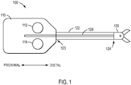
- Surgical instrument 100 may include a force transmission mechanism 110, a shaft 122 connected to force transmission mechanism 110 at a proximal end 123 of shaft 122, and an end effector 120 connected to a distal end 124 of shaft 122.
- Shaft 122 may be flexible.
- shaft 122 may have a diameter ranging from about 3 mm to about 15 mm.
- the diameter of shaft 122 may range, for example, from about 5 mm to about 8 mm.
- Surgical instrument 100 may include one or more members to translate force between force transmission mechanism 110 and end effector 120.
- one or more drive element(s) 126 may connect force transmission mechanism 110 to end effector 120 to provide actuation forces to end effector 120, such as by extending through an interior of shaft 122.
- force transmission mechanism 110 may actuate end effector 120 to, for example, control a wrist mechanism (not shown in FIG. 1 ) of instrument 100 and/or to control a jaw of end effector 120 (or other moveable part).
- end effector 120 may be fixed to shaft 122, force translated from force translation mechanism 110 to end effector 120 may in turn be translated to shaft 122, such as when force translation mechanism 110 actuates end effector 120 in a rolling motion.
- Drive element(s) 126 may be in the form of tension elements, such as when force transmission mechanism 110 is a pull-pull mechanism, or one or more drive element rods or push rods, such as when force transmission mechanism 110 is a push-pull mechanism, as described in U.S. Patent No. 8,545,515 .
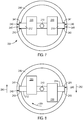
- Force transmission mechanism 110 may include one or more components to engage with a patient side cart of a teleoperated surgical system to translate a force provided by patient side cart to surgical instrument 100.
- force transmission mechanism 110 may include one or more interface disks 112, 114 that engage with a manipulator of a patient side cart, as described in U.S. Patent No. 8,545,515 .
- interface disks 112, 114 utilize actuation forces from a manipulator to actuate instrument 100.
- first disk 112 may be configured to provide a rolling motion to shaft 122 and provide a roll DOF for end effector 120, while second disk 114 may operate a jaw mechanism of end effector 120 to open and close.
- the force transmission mechanism may include other interface disks that actuate various other functionalities of a surgical instrument, as those having ordinary skill in the art are familiar with.
- an exemplary surgical instrument 200 for a teleoperated surgical system includes a shaft 202, clevis 204, and an end effector 206.
- surgical instrument 200 may include a wrist that couples the clevis 204 to the shaft 202, or surgical instrument 200 may be a non-wristed instrument. If surgical instrument 200 lacks a wrist, end effector 206 may be directly connected to clevis 204 and clevis 204 may be directly connected to shaft 202.
- end effector 206 may include a first jaw 220 and a second jaw 230.
- First jaw 220 may include a grip portion 222, a connection aperture 224, and an actuation aperture 226.
- second jaw 230 may include a grip portion 232, a connection aperture 234, and an actuation aperture 236.
- connection apertures 224, 234 may be used to connect jaws 220, 230 to clevis 304, which is in turn connected to shaft 202.
- a rivet or pin 208 may be inserted through connection apertures 224, 234 and through an aperture 205 in clevis 204 to connect jaws 220, 230 to clevis 204.
- Pin 208 may also serve as an axis of rotation about which jaws 220, 230 rotate when end effector 206 is actuated to open and close jaws 220, 230, which will be described below.
- Surgical instrument 200 may include a mechanism to actuate end effector 206, such as to open and close jaws 220, 230.
- surgical instrument may include a drive element 210 connected to end effector 206.
- a proximal end (not shown) of drive element 210 may be connected to a manipulator (not shown) of a teleoperated surgical system that provides motive force to drive element 210.
- drive element 210 may be a push/pull drive element rod that is pushed or pulled along direction 213 in FIG. 3 by a motive force provided by the manipulator to actuate end effector 206.
- a distal end 215 of drive element 210 may be connected to end effector 206 to translate the motive force from the manipulator to the jaws 220, 230.
- distal end 215 of drive element 210 may include a first projection 212 connected to jaw 220 and a second projection 214 connected to jaw 230.
- jaw 220 may include an actuation aperture 226 that first projection 212 is inserted into and jaw 230 may include an actuation aperture 236 that second projection 214 is inserted into.
- Actuation apertures 226, 236 may be in form of, for example, elongated slots, such as rectangular or oval slots that projections 212, 214 may be inserted into.
- projections 212, 214 may slide within actuation apertures 226, 236, causing jaws 220, 230 to pivot about pin 208.
- FIG. 4 a side view of end effector 206 is shown along line 4-4 in FIG. 2 but without clevis 204 and pin 208.
- the jaws 220, 230 of end effector 206 are in a closed state.
- drive element 210 is not shown in FIG. 4
- second projection 214 is shown within actuation slot 236 of jaw 230.
- drive element 210 is pushed in direction 217 in FIG. 4
- second projection 214 is forced upwards. Consequently, jaws 220, 230 rotate and pivot about pin (not shown) located in connection aperture 234 in direction 219 in FIG. 5 , causing jaws 220, 230 to separate and open.
- Surgical instrument 200 may include one or more features to assist with the movement of drive element 210 during actuation of end effector 206, such as between the closed and open states shown in the example of FIGS. 4 and 5 , respectively.
- clevis 204 may include one or more features to assist with the movement of drive element 210.
- FIG. 6 a cut away view of an exemplary clevis 204 is provided.
- Clevis 204 includes a sidewall 246 that forms an outer surface of clevis 246 and in FIG. 6 a portion of sidewall 246 has been removed to show internal features of clevis 204.
- Clevis 204 may include a lumen 244 for passage of drive element 210 through clevis 204 and an aperture 205 for a pin 208 to connect jaws 220, 230 of an end effector 206, as discussed above in regard to the example of FIG. 3 .
- clevis 204 may include other lumens for other components, such as, for example, conduits to provide energy to end effector 206 (e.g., electrical wires) and/or additional actuation components (e.g., an actuation element for an additional degree of freedom for surgical instrument or for a component, such as a knife).
- clevis 204 may include one or more features to interact with the projections 212, 214 of drive element 210.
- clevis 204 may include a groove 240 in the sidewall 246, as shown in the example of FIG. 6 .
- groove 240 may have a finite depth and a bottom surface 245, as shown in FIG. 6 .
- the configuration of groove 240 is not limited to such a geometry and groove 240 may instead be provided as a slot (not shown) that passes completely through sidewall 246 of clevis 204.
- One or more projections 212, 214 of drive element 210 may be configured to extend into groove 240 so that when drive element 210 is moved to actuate end effector 206, groove 240 supports a projection 212, 214.
- one or more projections 212, 214 of drive element 210 may have a length sufficient to extend through jaws 220, 230 (such as through actuation apertures 226, 236) and into groove 240 in sidewall 246.
- FIG. 7 a cross-section view is shown along line 7-7 of FIG. 4 is shown but with clevis 204 also provided.
- FIG. 8 depicts a cross-sectional view along line 8-8 of FIG. 5 but with clevis also provided.
- clevis 204 may include two grooves 240; one for each projection 212, 214 of drive element 210.
- grooves 240 may be opposed to one another, as shown in FIG. 7 . Because projections 212, 214 of drive element 210 are placed within grooves 240, when drive element 210 is moved to actuate an end effector 206 (e.g., by moving drive element 210 in and out of the page of FIG.
- grooves 240 support and/or guide the movement of projections 212, 214 and thus drive element 210.
- at least one of sidewalls 241, 243 of groove 240 may contact projections 212, 214 as drive element 210 is moved and projections 212, 214 slide back and forth within groove 240.
- a bottom surface 245 of groove 240 may be in contact with projections 212, 214 to support projections 212, 214, either alternatively or in addition to contact with one or more sidewalls 241, 243.
- FIG. 9 a cut-away view of an exemplary clevis 204 is shown, which is similar to the view of FIG. 6 , except that the end of projection 212 is shown within groove 240.
- projection 212 may contact sidewalls 241, 243 of groove 240, such as at contact portions 248, so that projection 212 is supported by groove 240.
- contact portions 248 may be characterized by contact between a circle and a planar surface.
- contact portions 248 may be a substantially tangential contact portion between projections 212, 214 and sidewalls 214, 243 of groove 240.
- contact portions 248 may have a shape of line or a point.
- FIGS. 7 and 8 When drive element 210 is moved to actuate an end effector 206 to open and close jaws 220, 230, portions of jaws 220, 230 may move apart from one another. This is also demonstrated in FIGS. 7 and 8 .
- jaws 220, 230 are in a closed position, as shown in the example of FIG. 4 .
- FIG. 8 jaws 220, 230 have been moved to an open position due to the movement of drive element 210, as shown in the example of FIG. 5 .
- the proximal ends of jaws 220, 230 may move in different directions when jaws 220, 230 move to an open position, as shown in the example of FIG. 5 .
- FIG. 8 shows that the end of jaw 220 has moved in direction 250 relative to FIG. 7 and that the end of jaw 230 has moved in direction 252 relative to FIG. 7 .
- Torque in direction 254 causes drive element 210 to twist, resulting in projection 212 exerting force against sidewall 243 of one groove 240 and projection 214 exerting force against sidewall 241 of another groove 240.
- the force exerted between projections 212, 214 and sidewalls 241, 243 is limited to small areas.
- grooves 240 may permanently deform and/or wear as projections 212, 214 slide back and forth within grooves 240 and press against sidewalls 241, 243.
- jaws 220, 230 may move in opposite directions to directions 250, 252 shown in the example of FIG. 8 when jaws 220, 230 are actuated to a closed position, which may result in a torque and twisting motion in a direction opposite to direction 254 in FIG. 8 .
- clevis 204 may be made from a non-metallic material.
- clevis 204 may be made of a plastic, such as, for example polyether ether ketone (PEEK), including glass filled PEEK.
- PEEK polyether ether ketone
- clevis 204 is made of a non-metallic material, for example, a plastic material, permanent deformation and/or wear may occur on the surfaces of grooves 240, such as sidewalls 241, 243.
- forces between projections 212, 214 and sidewalls 241, 241 may even be sufficient for projections to pop out of grooves 240 when drive element 210 is twisted in direction 254, particularly when sidewalls 241, 243 have become worn.
- a surgical instrument with enhanced durability.
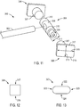
- Push/pull drive element 300 may be, for example, a push rod, a wire, a cable, or other structure known by one of ordinary skill in the art for use as a push/pull drive element.
- push/pull drive element may be an element with sufficient columnar compressibility to transmit an axial pushing force applied to the push/pull drive element.
- Push/pull drive element 300 may be used according to the same functions as drive element 210 described above for the examples of FIGS. 2-9 .
- push/pull drive element 300 may include a shaft 302 connected to a head 304.
- Head 304 may include, for example, a cross shaft 309 and end portions 306, as shown in FIG. 11 .
- Cross shaft 309 may also be referred to, for example, as a main portion of head 304.
- Head 304 may be formed from separate pieces, such as cross shaft 309 and end portions 306, as shown in the examples of FIGS. 10 and 11 , or head 304 may be provided with a single piece construction by providing cross shaft 309 and end portions 306 as a single piece.
- portions of push/pull drive element 300 such as shaft 302 and cross shaft 309 and end portions 306, may be made of a metal.
- portions of push/pull drive element 300 may be made of a wear resistant stainless steel alloy, such as Nitronic® 60.
- push/pull drive element 300 may include an insulative material 308, such as when push/pull drive element 300 is used in a surgical instrument is energized, as will be discussed below.
- Insulative material 308 may be a material that minimizes arcing and electrical conductivity, such as, for example, a plastic material.
- insulative material 308 may be provided on at least a portion of cross shaft 309 and shaft 302.
- insulative material 308 may be provided on at least one of cross shaft 309 and shaft 302 by overmolding the insulative material 308.
- cross shaft 309 includes engagement portions 310 that engage with portions of an end effector when push/pull drive element 300 is moved to actuate the end effector.
- engagement portions 310 may be configured to engage actuation apertures 226, 236 of jaws 220, 230 of end effector 206, as described above in the examples of FIGS. 2-5 , to actuate end effector 206 when push/pull drive element 300 is moved.
- engagement portions 310 may have a circular cross-section, like projections 212, 214 of the examples of FIGS. 2-8 .
- engagement portions 310 of cross shaft 309 may have a diameter 311 (see FIG.
- diameter 311 of engagement portions 310 need not be substantially the same diameter 247 of projections 212, 214, but instead may be different. For instance, the diameter 311 of engagement portions 310 may be smaller than the diameter 247 of projections 212, 214.
- engagement portions 310 may have a non-circular cross-section.
- a cross-sectional shape of engagement portions 310 may include one or more flat surface portions (not shown).
- One or more flat surface portions may be provided to increase the contact area between engagement portions 310 and actuation apertures 226, 236 of jaws 220, 230, such as to increase the distribution of forces exerted between engagement portions 310 and jaws 220, 230.
- actuation apertures 226, 236 of jaws 220, 230 may have a different shape than the shape shown in the example of FIGS. 2 and 3 .
- actuation apertures 226, 236 may be curved, instead of being straight as shown in FIGS. 2 and 3 .
- actuation apertures 226, 236 may be curved so that actuation apertures 226, 236 are either convex or concave in shape relative to connection apertures 224, 234 in the example of FIG. 3 .
- End portions 306 of push/pull drive element 300 may be configured to enhance the distribution of forces between end portions 306 and other components of a surgical instrument, such as a clevis. As shown in the example of FIGS. 10 and 11 , end portions 306 may be larger than engagement portions 310 of cross shaft 309. For instance, engagement portions 310 may have a diameter or width 311, while end portions 306 may have a width 313 or 315 that is larger than the width 311 of engagement portions 310. If dimensions 313, 315 of end portions 306 are not equal or substantially equal, the width of end portions 306 may be the larger of dimensions 313, 315, according to an example.
- dimension 315 of end portion 306 is larger than dimension 313, dimension 315 is the width of end portions and is also larger than the width 311 of engagement portions 310.
- a ratio of dimension 315 to diameter 311 is greater than 1.
- a ratio of dimension 315 to diameter 311 ranges from, for example, about 1.1 to about 1.3.
- dimension 315 may have a length of, for example, about 1.9 mm (0.075 inches) while diameter 311 is, for example, about 1.55 mm (0.061 inches).
- End portions 306 of push/pull drive element 300 may have a cross-section with various shapes. As shown in the example of FIGS. 10 and 11 , end portions 306 may have a rectangular shape. As shown in the example of FIG. 12 , end portions 306 may have a square shape. According to another example, an end portion 320 may have an oval shape, as shown in FIG. 13 . The oval shape may include flat surfaces 322, 324 and rounded ends 323, as shown in the example of FIG. 13 . However, the cross-sectional shape of end portions of a push/pull drive element is not limited to the examples of FIGS. 10-13 and other shapes may be utilized.
- a cross-sectional shape of an end portion of a push/pull drive element includes one or more flat surface portions.
- end portions 306 may include flat surface portions 317, 319.
- an end portion 320 having an oval shape or other non-rectangular or non-square shape may have flat surface portions 322, 324, as shown in the example of FIG. 13 .
- flat surface portions may be opposite to one another and substantially in planes that are parallel to the elongated direction of the groove 240 of the clevis, as shown in the examples of FIGS. 11-13 .
- end portions 306 By providing end portions 306 with a cross-section that is enlarged relative to that of the cross shaft 309, providing end portions 306 having a shape described above, and/or providing end portions 306 having at least one flat surface portion in a plane parallel to the elongated direction of the groove 240 of the clevis, a contact area between end portions 306 and a clevis of a surgical instrument may be increased. This in turn may enhance the distribution of forces between end portions 306 and the clevis.
- a cut away view of a clevis 330 is provided to show internal features of clevis 330, including groove 340 formed in a sidewall 336 of clevis 330.
- Clevis 330 may further include an aperture 335 for a pin (not shown) to connect the jaws of an end effector and groove 340 may include sidewalls 341, 343.
- an end portion 306 of a push/pull drive element 300 may be placed within groove 340 so that groove 340 supports and/or guides end portion 306 as push/pull drive element 300 moves back and forth to actuate an end effector.
- the one or more surface portions of end portion 306 may be in contact with one or more surfaces of groove 340.
- FIG. 15 which is side view of clevis 340 and push/pull drive element 300, with an end portion 306 of push/pull drive element 300 located within groove 340, surface portions 317, 319 of end portion 306 may engage one or both of sidewalls 341, 343 of groove 340 via contact portions 350.
- surface portions 317, 319 may be flat. Because end portion 306 has one or more surface portions 317, 319, contact portions 350 between end portion 306 and sidewalls 341, 343 of groove 340 are not limited to point contacts or approximately tangential contacts, as discussed above in regard to the example of FIG. 9 , but instead provide relatively large contact areas over which the forces exerted between end portion 306 and groove 340 may be distributed.
- end portions 306 of push/pull drive element 300 have enhanced resistance to the forces exerted when push/pull drive element 300 actuates an end effector and is subjected to twisting, as described above in regard to the example of FIGS. 7 and 8 .
- push/pull drive element 300 may include an insulative material 308, particularly when push/pull drive element 300 is used in an energized surgical instrument.
- the examples described herein are not limited to energized surgical instruments and a push/pull drive element may be used in a non-energized surgical instrument.
- FIG. 16 a cut-away view of a non-energized surgical instrument 400 is shown.
- Surgical instrument 400 may include a shaft 402, clevis 404, end effector 406, and a push/pull drive element 410.
- End effector 406 may include jaws 420, 430 that may be connected to clevis 404 by a pin 408 inserted through an aperture 405.
- Push/pull drive element 410 may be configured according to the examples of FIGS. 10-15 except that push/pull drive element 410 does not include insulative material 308 because surgical instrument 400 is not energized.
- push/pull drive element 410 may include a shaft 412, one or more engagement portions 414 (such as, for example, engagement portions 414 provided by a cross shaft, as discussed above in regard to FIG. 11 ), and one or more end portions 416.
- End portion 416 may be inserted within a groove 440 of clevis 404, as discussed above in regard to the examples of FIGS. 10-15 , so that end portion 416 is guided and/or supported when push/pull drive element 410 moves back and forth to actuate end effector 406.
- end portions of a push/pull drive element Due to the shape and size of end portions of a push/pull drive element as described in the examples of FIGS. 10-17 , the amount of contact area between the end portions and a clevis groove is significantly increased.
- the end portions may advantageously enhance the distribution of force exerted between the end portions and grooves of a clevis.
- end portions of a push/pull drive element may counteract torque and a twisting motion applied to the push/pull drive element during actuation of an end effector, which may otherwise lead to deformation or wear of the clevis groove or the push/pull drive element popping out of the clevis groove.
- end portions of a push/pull drive element may minimize or reduce permanent deformation or wear of a groove of a clevis made of a non-metallic material, such as a plastic.
- an electrical connection is provided between an end effector of the surgical instrument and one or more conduits providing electrical energy to the end effector.
- an end effector of the surgical instrument When a surgical instrument is energized, an electrical connection is provided between an end effector of the surgical instrument and one or more conduits providing electrical energy to the end effector.
- providing and maintaining a connection between the one or more conduits and the end effector may be difficult.
- the level of difficultly of providing a connection that is functional and durable is relatively high.
- an outer diameter of a surgical instrument may be, for example, approximately 5 mm.
- FIG. 18 an exemplary embodiment of a surgical instrument 500, according to the present invention, is shown that includes jaws 502, 504 connected via a pin 508, a clevis 506, and a push/pull drive element 510.
- Push/pull drive element 510 may be configured according to the examples of FIGS. 10-17 .
- surgical instrument 500 further includes a connector assembly 530 to connect one or more conduits 520, 522 to jaws 502, 504. Conduits 520, 522 may provide energy to jaws 502, 504, such as, for example electrical energy, to energize jaws 502, 504.
- FIG. 19 shows surgical instrument 500 with jaw 504 removed so that components of surgical instrument 500 may be more easily viewed, such as connector assembly 530.
- Surgical instrument 500 may further include a shaft (not shown) connected to clevis 506 and covering conduits 520, 522.
- jaws 502, 504 When jaws 502, 504 are actuated, jaws 502, 504 move relative to other components of surgical instrument 500. For instance, jaws 502, 504 may pivot in direction 540 relative to pin 508, as shown in the exemplary embodiments of FIGS. 18 and 19 . Due to the movement of jaws 502, 504, providing a connection between conduits 520, 522 and jaws 502, 504 can be challenging. For instance, if conduits 520, 522 are directly connected to jaws 502, 504, at least a portion of conduits 520, 522 may move when jaws 502, 504 move, which may lead to challenges in providing a durable connection between jaws 502, 504 and conduits.
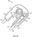
- FIG. 20 an exemplary embodiment of a connector assembly 530 is shown, which includes a body 531.
- Connector assembly 530 provides a connection between one or more conduits 520, 522 and an end effector, such as jaws 502, 504, so that energy (e.g., electrical energy) may be provided from the one or more conduits 520, 522 to the end effector.
- energy e.g., electrical energy
- connector assembly 530 provides an electrical connection between one or more conduits 520, 522 and an end effector in this exemplary embodiment.
- body 531 is made of an electrically insulative material.
- body 531 may be made of a plastic, such as, for example, a polyphthalamide (PPA) (e.g., Amodel®, which is sold by Solvay Advanced Polymers, L.L.C.).
- PPA polyphthalamide
- Body 531 may be used, for instance, to provide a structural support for a connection between one or more conduits 520, 522 and jaws 502, 504 while substantially insulating components of surgical instrument 500 from the energy connected between the one or more conduits 520, 522 and jaws 502, 504.
- body 531 is approximately U-shaped and may include a first leg 532 and a second leg 534.
- legs 532, 534 may be separated by a gap 536, as shown in the exemplary embodiment of FIG. 20 .
- Gap 536 may, for example, provide space for movement of push/pull drive element 510 within body 531, as shown in the exemplary embodiment of FIG. 19 , such as when push/pull drive element 510 is moved to actuate jaws 502, 504.
- Body 531 further includes a lumen 538 that pin 508 may be inserted through, as shown in the exemplary embodiment of FIGS. 18 and 19 .
- legs 532, 534 of body include a structure to receive conduits 520, 522.
- leg 534 includes a cavity 533 to receive conduit 520, as shown in the exemplary embodiment of FIG. 20 .
- Cavity 533 may be open, as shown in the exemplary embodiment of FIG. 20 , or cavity may be at least partially covered.
- Conduit 520 may be received in cavity 533 by, for example, inserting conduit 520 through an aperture 535 in leg 534.
- Leg 532 may be configured according to any of the above exemplary embodiments discussed for leg 534.
- connector assembly 530 further includes one or more connector portions 550.
- connector assembly 530 may include a connector portion 550 for each conduit.
- connector assembly 530 may include a connector portion 550 for each of conduits 520, 522, as shown in FIG. 21 .
- Connector portions 550 may be attached to body 531.
- connector portions 550 may be fit over protuberances 537.
- Connector portions 550 may have a shape corresponding to the shape of protuberances 537.
- connector portions 550 may be press fit to protuberances 537, according to an exemplary embodiment.
- protuberances 537 may connect to clevis 506 to attach connector assembly 530 and clevis 506.
- Connector portions 550 may include one or more structures to attach a conduit.
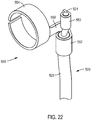
- FIG. 22 which depicts an exemplary embodiment of conduit 520 attached to connector portion 550
- connector portion 550 may include a first attachment 553 and a second attachment 552.
- the second attachment 552 connects connector portion 550 to conduit 520.
- conduit 520 includes more than one component, such as an outer insulative cover 523 and a conductor 521, as shown in the exemplary embodiment of FIG. 22
- second attachment 552 may connect to insulative cover 523 while first attachment 553 connects to an exposed portion of conductor 521.
- second attachment 552 may be provided, for example, to assist with maintaining a position of conductor 520 relative to connector portion 550, while first attachment 553 is provided to form an electrically conductive contact between connector portion 550 and conduit 520, particularly conductor 521.
- Attachments 552, 553 may be attached to conduit 520 via a mechanical connection, such as, for example, crimping attachments 552, 553 to conduit 520, via a bond, such as solder (e.g., soldering attachment 553 to conductor 521), or other joining method known to one of ordinary skill in the art.
- Conduit 522 may be connected to connector portion 550 in the same way, according to an exemplary embodiment.
- Connector portions 550 may further include one or more structures to contact a portion of an end effector.
- connector portions 550 may include a contact portion 554 to contact at least one of jaws 502, 504.
- Contact portion 554 may contact at least one of jaws 502, 504 via sliding contact, according to an exemplary embodiment.
- jaw 504 may include an aperture 505 so that jaw 504 may be fit over contact portion 554.
- aperture 505 may be structured to have a shape and size corresponding to contact portion 554 so that the portion of jaw 504 forming aperture 505 is in contact with contact portion 554.
- contact portions 554 may have a split ring shape, as shown in the exemplary embodiments of FIGS.
- jaw 504 moves, such as by pivoting in direction 540 relative to pin 508, jaw 504 remains in contact with contact portion 554.
- Jaw 502 may be configured according to the exemplary embodiments of jaw 504 to also form a sliding contact with a contact portion 554 of a connector assembly 530.
- a connection such as an electrical connection, may be provided between conduits 520, 522 and jaws 502, 504 that is advantageously durable while permitting movement of jaws 502, 504 and providing energy to jaws 502, 504 from conduits 502, 504.
- connectors 530 may be configured so that jaws 502, 504 move independently of contact portions 554. For instance, when jaws 502, 504 move, such as when jaws 502, 504 are actuated to pivot in direction 540 about pin 508, as shown in the exemplary embodiment of FIGS. 18 and 19 , contact portion 554 remains substantially stationary as jaw 504 slides over contact portion 554. As a result, conduits 520, 522 connected to connectors 530 may also remain substantially stationary as jaws 502, 504, which may advantageously minimize or reduce wear or deformation of conduits 520, 522 and connections between conduits 520, 522 and connectors 530. Further, conduits 520, 522 are not directly connected to jaws 502, 504 because connectors 530 form connections between conduits 520, 522 and jaws 502, 504.
- a contact portion 554 may be connected to the one or more attachment(s) 552, 553 of connector portions 550 by a bridge 556, as shown in the exemplary embodiment of FIG. 22 .
- connector portions 550 may have a single piece construction.
- the one or more attachment(s) 552, 553, contact portion 554, and bridge 556 may be formed from a single piece, although the exemplary embodiments of connector portions 550 described herein are not limited to a single piece construction.
- connection portions 550 may be made of a conductive material, such as an electrically conductive material, so that energy provided by conduits 520, 522 may be provided to jaws 502, 504 via connector portions 550.
- connection portions 550 may be made of a metal, such as, for example, a stainless steel.
- a connection may be advantageously provided between the push/pull drive element and a component of the surgical instrument that has enhanced durability while permitting push/pull drive element to move and actuate an end effector of the surgical instrument.
- a connection may be advantageously provided between one or more conduits and the end effector that is durable, while permitting movement of the end effector and providing energy to the end effector from the one or more conduit(s).
Description
- Aspects of the present disclosure relate to a surgical instrument for a teleoperated (robotic) surgical system. Further aspects relate to a drive element for a surgical instrument and an electrical connection for a surgical instrument.
- Some minimally invasive surgical techniques are performed remotely through the use of teleoperated (robotically-controlled) surgical instruments (which may also be referred to as tools). In teleoperated surgical systems, surgeons manipulate input devices at a surgeon console, and those inputs are passed to a patient side cart that interfaces with one or more teleoperated surgical instruments. Based on the surgeon's inputs at the surgeon console, the one or more teleoperated surgical instruments are actuated at the patient side cart to operate on the patient, thereby creating a master-slave control relationship between the surgeon console and the surgical instrument(s) at the patient side cart.
- Teleoperated surgical systems may have multiple arms to which surgical instruments may be coupled. The surgical instruments include end effectors used to perform surgical procedures. An end effector may be actuated by a drive element. Further, when the end effector is energized, such as for a cauterization procedure, the surgical instrument includes an electrical connection to provide electrical energy to the end effector. It is desirable to provide drive elements and electrical connections with enhanced durability while also performing their respective functions within the small space of a surgical instrument.
-
US 2012/078040 A1 discloses a treatment instrument for endoscope that includes a first and a second forceps members having a conductive electrode part; a forceps rotation axis that supports the forceps members so that they can rotate relative to each other, a first and a second link members being connected via a rotation axis to the forceps members respectively, and make the forceps members open and close, a link support member supporting the forceps members in a state where they are separated at a predetermined interval when they are opened and closed, an operation part connecting to the link support member, and opens and closes the forceps members by moving the link members, and a power supply wire, one end thereof being connected to the electrode part by being attached to the forceps rotation axis, and another end thereof being connected to a current supply means providing a current to the electrode part. - According to the present invention there is provided the surgical instrument of claim 1. Additional aspects of the invention are set out in the dependent claims.
- There is hereinafter disclosed a surgical instrument comprising a shaft, an end effector connected to the shaft, and a push/pull drive element. The push/pull drive element comprises a head that extends perpendicular to a push/pull direction of the push/pull element. The head of the push/pull drive element may have end portions each having a cross-section that differs from a cross-section of a main portion of the head between the end portions.
- Disclosed also is a surgical instrument that comprises a shaft, an end effector connected to the shaft, and a push/pull drive element. The push/pull drive element may include an engagement portion and an end portion connected to an end of the engagement portion. The engagement portion may be in contact with the end effector to actuate the end effector. The engagement portion may have a first width and the end portion may have a second width, wherein the second width is greater than the first width.
- Additional objects, features, and/or advantages will be set forth in part in the description which follows, and in part will be obvious from the description, or may be learned by practice of the present disclosure and/or claims. At least some of these objects and advantages may be realized and attained by the elements and combinations particularly pointed out in the appended claims.
- It is to be understood that both the foregoing general description and the following detailed description are exemplary and explanatory only and are not restrictive of the claims; rather the claims should be entitled to their full breadth of scope.
- The present disclosure can be understood from the following detailed description, either alone or together with the accompanying drawings. The drawings are included to provide a further understanding of the present disclosure, and are incorporated in and constitute a part of this specification. The drawings illustrate one or more exemplary embodiments of the present teachings. They also illustrate examples of surgical instrument which, although not in accordance with the present invention, nevertheless may be useful for understanding the present invention. The drawings, together with the description, serve to explain certain principles and operation.
-
FIG. 1 is a top view of an exemplary surgical instrument including a force transmission mechanism. -
FIG. 2 is a partial perspective view of an exemplary surgical instrument having an end effector. -
FIG. 3 is an exploded view of the surgical instrument ofFIG. 2 . -
FIG. 4 is a side view of the end effector ofFIG. 2 , along line 4-4 ofFIG. 2 , the end effector being in a closed position. -
FIG. 5 is a view of the end effector ofFIG. 4 in an open position. -
FIG. 6 is a cut-away view of an exemplary clevis of a surgical instrument in accordance with the present disclosure. -
FIG. 7 is a cross-section view along line 7-7 ofFIG. 4 but with an exemplary clevis also shown. -
FIG. 8 is a cross-sectional view along line 8-8 ofFIG. 5 but with an exemplary clevis also shown. -
FIG. 9 is a cut-away view of an exemplary clevis and an end of a projection of a drive element located within a groove of the clevis. -
FIG. 10 is a partial perspective view of an exemplary push/pull drive element. -
FIG. 11 is an exploded view of the push/pull drive element ofFIG. 10 . -
FIG. 12 is an end view of the push/pull drive element ofFIG. 10 . -
FIG. 13 is an end view of another exemplary push/pull drive element. -
FIG. 14 is a partial cut-away view of an exemplary surgical instrument clevis and a push/pull drive element. -
FIG. 15 is a partial cut-away view of an exemplary clevis and an end of a projection of a push/pull drive element. -
FIG. 16 is a partial cut-away view of an exemplary non-energized surgical instrument. -
FIG. 17 is a cut-away view of an exemplary surgical instrument clevis and a push/pull drive element. -
FIG. 18 is a partial side cut-away view of an exemplary embodiment of a surgical instrument according to the present invention. -
FIG. 19 is a partial side cut-away view of the surgical instrument ofFIG. 18 with a jaw removed. -
FIG. 20 is a perspective view of an exemplary embodiment of a connector assembly. -
FIG. 21 is an exploded view of the connector assembly ofFIG. 20 . -
FIG. 22 is a perspective view of an exemplary embodiment of a connection portion of a connector assembly. - Exemplary embodiments discussed herein regard a surgical instrument for a teleoperated surgical system. The surgical instrument may be relatively simple and inexpensive to manufacture, while providing a robust configuration resulting in a relatively durable instrument able to perform multiple functions within a relatively compact design.
- This description and the accompanying drawings that illustrate exemplary embodiments should not be taken as limiting. Various mechanical, compositional, structural, electrical, and operational changes may be made without departing from the scope of this description and the invention as claimed. In some instances, well-known structures and techniques have not been shown or described in detail so as not to obscure the disclosure. Like numbers in two or more figures represent the same or similar elements. Furthermore, elements and their associated features that are described in detail with reference to one embodiment may, whenever practical, be included in other embodiments in which they are not specifically shown or described. For example, if an element is described in detail with reference to one embodiment and is not described with reference to a second embodiment, the element may nevertheless be included in the second embodiment.
- For the purposes of this specification, unless otherwise indicated, all numbers expressing quantities, percentages, or proportions, and other numerical values used in the specification, are to be understood as being modified in all instances by the term "about," to the extent they are not already so modified. Accordingly, unless indicated to the contrary, the numerical parameters set forth in the following specification are approximations that may vary depending upon the desired properties sought to be obtained. At the very least, each numerical parameter should at least be construed in light of the number of reported significant digits and by applying ordinary rounding techniques.
- It is noted that, as used in this specification and the appended claims, the singular forms "a," "an," and "the," and any singular use of any word, include plural referents unless expressly and unequivocally limited to one referent. As used herein, the term "include" and its grammatical variants are intended to be non-limiting, such that recitation of items in a list is not to the exclusion of other like items that can be substituted or added to the listed items.
- This description's terminology is not intended to limit the present disclosure or claims. For example, spatially relative terms-such as "beneath", "below", "lower", "above", "upper", "proximal", "distal", and the like-may be used to describe one element's or feature's relationship to another element or feature as illustrated in the figures. These spatially relative terms are intended to encompass different positions (i.e., locations) and orientations (i.e., rotational placements) of a device in use or operation in addition to the position and orientation shown in the figures. For example, if a device in the figures is turned over, elements described as "below" or "beneath" other elements or features would then be "above" or "over" the other elements or features. Thus, the exemplary term "below" can encompass both positions and orientations of above and below. A device may be otherwise oriented (rotated 90 degrees or at other orientations) and the spatially relative descriptors used herein interpreted accordingly.
- Teleoperated surgery generally involves the use of a manipulator that has multiple manipulator arms. One or more of the manipulator arms often support a surgical instrument. One or more of the manipulator arms may be used to support a surgical image capture device, such as an endoscope (which may be any of a variety of structures such as a laparoscope, an arthroscope, a hysteroscope, or the like), or, optionally, some other imaging modality (such as ultrasound, fluoroscopy, magnetic resonance imaging, or the like). Typically, the manipulator arms will support at least two surgical tools corresponding to the two hands of a surgeon and one image capture device. Such teleoperated surgical systems are described in
U.S. Patent No. 8,545,515 entitled "Curved Cannula Surgical System," issued on October 1, 2013. - Turning to
FIG. 1 , a side view of an exemplarysurgical instrument 100 for a teleoperated surgical system is shown.Surgical instrument 100 may include aforce transmission mechanism 110, ashaft 122 connected to forcetransmission mechanism 110 at aproximal end 123 ofshaft 122, and anend effector 120 connected to adistal end 124 ofshaft 122.Shaft 122 may be flexible. According to an example,shaft 122 may have a diameter ranging from about 3 mm to about 15 mm. According to another example, the diameter ofshaft 122 may range, for example, from about 5 mm to about 8 mm.Surgical instrument 100 may include one or more members to translate force betweenforce transmission mechanism 110 andend effector 120. For instance, one or more drive element(s) 126 may connectforce transmission mechanism 110 to endeffector 120 to provide actuation forces to endeffector 120, such as by extending through an interior ofshaft 122. By utilizing drive element(s) 126,force transmission mechanism 110 may actuateend effector 120 to, for example, control a wrist mechanism (not shown inFIG. 1 ) ofinstrument 100 and/or to control a jaw of end effector 120 (or other moveable part). Further, becauseend effector 120 may be fixed toshaft 122, force translated fromforce translation mechanism 110 to endeffector 120 may in turn be translated toshaft 122, such as whenforce translation mechanism 110 actuatesend effector 120 in a rolling motion. Drive element(s) 126 may be in the form of tension elements, such as whenforce transmission mechanism 110 is a pull-pull mechanism, or one or more drive element rods or push rods, such as whenforce transmission mechanism 110 is a push-pull mechanism, as described inU.S. Patent No. 8,545,515 . -
Force transmission mechanism 110 may include one or more components to engage with a patient side cart of a teleoperated surgical system to translate a force provided by patient side cart tosurgical instrument 100. According to an example,force transmission mechanism 110 may include one ormore interface disks U.S. Patent No. 8,545,515 . Thus,interface disks instrument 100. For instance,first disk 112 may be configured to provide a rolling motion toshaft 122 and provide a roll DOF forend effector 120, whilesecond disk 114 may operate a jaw mechanism ofend effector 120 to open and close. The force transmission mechanism may include other interface disks that actuate various other functionalities of a surgical instrument, as those having ordinary skill in the art are familiar with. - Turning to
FIG. 2 , an exemplarysurgical instrument 200 for a teleoperated surgical system is shown that includes ashaft 202,clevis 204, and anend effector 206. According to an example,surgical instrument 200 may include a wrist that couples theclevis 204 to theshaft 202, orsurgical instrument 200 may be a non-wristed instrument. Ifsurgical instrument 200 lacks a wrist,end effector 206 may be directly connected to clevis 204 andclevis 204 may be directly connected toshaft 202. As shown inFIG. 3 , which is an exploded view of the example ofFIG. 2 ,end effector 206 may include afirst jaw 220 and asecond jaw 230.First jaw 220 may include agrip portion 222, aconnection aperture 224, and anactuation aperture 226. Similarly,second jaw 230 may include agrip portion 232, aconnection aperture 234, and anactuation aperture 236. - According to an example,
connection apertures jaws clevis 304, which is in turn connected toshaft 202. For instance, as shown in the example ofFIGS. 2 and 3 , a rivet or pin 208 may be inserted throughconnection apertures aperture 205 inclevis 204 to connectjaws clevis 204.Pin 208 may also serve as an axis of rotation about whichjaws end effector 206 is actuated to open andclose jaws -
Surgical instrument 200 may include a mechanism to actuateend effector 206, such as to open andclose jaws FIG. 3 , surgical instrument may include adrive element 210 connected to endeffector 206. A proximal end (not shown) ofdrive element 210 may be connected to a manipulator (not shown) of a teleoperated surgical system that provides motive force to driveelement 210. For instance,drive element 210 may be a push/pull drive element rod that is pushed or pulled alongdirection 213 inFIG. 3 by a motive force provided by the manipulator to actuateend effector 206. - A
distal end 215 ofdrive element 210 may be connected to endeffector 206 to translate the motive force from the manipulator to thejaws distal end 215 ofdrive element 210 may include afirst projection 212 connected tojaw 220 and asecond projection 214 connected tojaw 230. For instance,jaw 220 may include anactuation aperture 226 thatfirst projection 212 is inserted into andjaw 230 may include anactuation aperture 236 thatsecond projection 214 is inserted into.Actuation apertures projections drive element 210 is pushed or pulled alongdirection 213 inFIG. 3 ,projections actuation apertures jaws pin 208. - Turning to
FIG. 4 , a side view ofend effector 206 is shown along line 4-4 inFIG. 2 but withoutclevis 204 andpin 208. In the example ofFIG. 4 , thejaws end effector 206 are in a closed state. Althoughdrive element 210 is not shown inFIG. 4 ,second projection 214 is shown withinactuation slot 236 ofjaw 230. Whendrive element 210 is pushed indirection 217 inFIG. 4 ,second projection 214 is forced upwards. Consequently,jaws connection aperture 234 indirection 219 inFIG. 5 , causingjaws -
Surgical instrument 200 may include one or more features to assist with the movement ofdrive element 210 during actuation ofend effector 206, such as between the closed and open states shown in the example ofFIGS. 4 and 5 , respectively. According to an example,clevis 204 may include one or more features to assist with the movement ofdrive element 210. Turning toFIG. 6 , a cut away view of anexemplary clevis 204 is provided.Clevis 204 includes asidewall 246 that forms an outer surface ofclevis 246 and inFIG. 6 a portion ofsidewall 246 has been removed to show internal features ofclevis 204.Clevis 204 may include alumen 244 for passage ofdrive element 210 throughclevis 204 and anaperture 205 for apin 208 to connectjaws end effector 206, as discussed above in regard to the example ofFIG. 3 . According to an example,clevis 204 may include other lumens for other components, such as, for example, conduits to provide energy to end effector 206 (e.g., electrical wires) and/or additional actuation components (e.g., an actuation element for an additional degree of freedom for surgical instrument or for a component, such as a knife). - To assist with the movement of
drive element 210,clevis 204 may include one or more features to interact with theprojections drive element 210. For instance,clevis 204 may include agroove 240 in thesidewall 246, as shown in the example ofFIG. 6 . According to an example, groove 240 may have a finite depth and abottom surface 245, as shown inFIG. 6 . However, the configuration ofgroove 240 is not limited to such a geometry and groove 240 may instead be provided as a slot (not shown) that passes completely throughsidewall 246 ofclevis 204. One ormore projections drive element 210 may be configured to extend intogroove 240 so that whendrive element 210 is moved to actuateend effector 206,groove 240 supports aprojection more projections drive element 210 may have a length sufficient to extend throughjaws 220, 230 (such as throughactuation apertures 226, 236) and intogroove 240 insidewall 246. - Turning to
FIG. 7 , a cross-section view is shown along line 7-7 ofFIG. 4 is shown but withclevis 204 also provided.FIG. 8 depicts a cross-sectional view along line 8-8 ofFIG. 5 but with clevis also provided. As shown in the example ofFIG. 7 , clevis 204 may include twogrooves 240; one for eachprojection drive element 210. In addition,grooves 240 may be opposed to one another, as shown inFIG. 7 . Becauseprojections drive element 210 are placed withingrooves 240, whendrive element 210 is moved to actuate an end effector 206 (e.g., by movingdrive element 210 in and out of the page ofFIG. 7 ),grooves 240 support and/or guide the movement ofprojections element 210. For instance, at least one ofsidewalls groove 240 may contactprojections drive element 210 is moved andprojections groove 240. According to an example, abottom surface 245 ofgroove 240 may be in contact withprojections projections FIG. 9 , a cut-away view of anexemplary clevis 204 is shown, which is similar to the view ofFIG. 6 , except that the end ofprojection 212 is shown withingroove 240. As shown in the example ofFIG. 9 ,projection 212 may contactsidewalls groove 240, such as atcontact portions 248, so thatprojection 212 is supported bygroove 240. Becauseprojections projections grooves 240,contact portions 248 may be characterized by contact between a circle and a planar surface. For instance,contact portions 248 may be a substantially tangential contact portion betweenprojections sidewalls groove 240. In other words, contactportions 248 may have a shape of line or a point. Thus, all of the stress transmitted betweenprojections sidewalls - When
drive element 210 is moved to actuate anend effector 206 to open andclose jaws jaws FIGS. 7 and 8 . InFIG. 7 ,jaws FIG. 4 . InFIG. 8 ,jaws drive element 210, as shown in the example ofFIG. 5 . In particular, the proximal ends ofjaws jaws FIG. 5 . This is also demonstrated inFIG. 8 , which shows that the end ofjaw 220 has moved indirection 250 relative toFIG. 7 and that the end ofjaw 230 has moved indirection 252 relative toFIG. 7 . - Because of the motions of
jaws respective directions drive element 210 indirection 254 shown in the example ofFIG. 8 . Torque indirection 254 causes driveelement 210 to twist, resulting inprojection 212 exerting force againstsidewall 243 of onegroove 240 andprojection 214 exerting force againstsidewall 241 of anothergroove 240. Further, due to the geometry ofcontact portions 248 betweenprojections sidewalls grooves 240, such as line or point contact, the force exerted betweenprojections sidewalls grooves 240 may permanently deform and/or wear asprojections grooves 240 and press againstsidewalls jaws directions FIG. 8 whenjaws direction 254 inFIG. 8 . - According to an example,
clevis 204 may be made from a non-metallic material. For instance,clevis 204 may be made of a plastic, such as, for example polyether ether ketone (PEEK), including glass filled PEEK. When clevis 204 is made of a non-metallic material, for example, a plastic material, permanent deformation and/or wear may occur on the surfaces ofgrooves 240, such assidewalls projections sidewalls grooves 240 whendrive element 210 is twisted indirection 254, particularly when sidewalls 241, 243 have become worn. - In view of these considerations, it may be desirable to provide a surgical instrument with enhanced durability. In particular, it may be desirable to provide a surgical instrument with one or more features to support and/or guide the movement of a drive element for an end effector that have enhanced durability, such as by enhancing the distribution of force between the drive element and another component of the surgical instrument.
- Turning to
FIG. 10 , a perspective view of an exemplary push/pull drive element 300 is shown. Push/pull drive element 300 may be, for example, a push rod, a wire, a cable, or other structure known by one of ordinary skill in the art for use as a push/pull drive element. For instance, push/pull drive element may be an element with sufficient columnar compressibility to transmit an axial pushing force applied to the push/pull drive element. Push/pull drive element 300 may be used according to the same functions asdrive element 210 described above for the examples ofFIGS. 2-9 . As shown inFIG. 10 , push/pulldrive element 300 may include ashaft 302 connected to ahead 304.Head 304 may include, for example, across shaft 309 and endportions 306, as shown inFIG. 11 .Cross shaft 309 may also be referred to, for example, as a main portion ofhead 304.Head 304 may be formed from separate pieces, such ascross shaft 309 and endportions 306, as shown in the examples ofFIGS. 10 and11 , orhead 304 may be provided with a single piece construction by providingcross shaft 309 and endportions 306 as a single piece. According to an example, portions of push/pull drive element 300, such asshaft 302 andcross shaft 309 and endportions 306, may be made of a metal. For example, portions of push/pull drive element 300 may be made of a wear resistant stainless steel alloy, such as Nitronic® 60. - According to an example, push/pull
drive element 300 may include aninsulative material 308, such as when push/pull drive element 300 is used in a surgical instrument is energized, as will be discussed below.Insulative material 308 may be a material that minimizes arcing and electrical conductivity, such as, for example, a plastic material. As shown in the example ofFIG. 10 ,insulative material 308 may be provided on at least a portion ofcross shaft 309 andshaft 302. For instance,insulative material 308 may be provided on at least one ofcross shaft 309 andshaft 302 by overmolding theinsulative material 308. - According to an example,
cross shaft 309 includesengagement portions 310 that engage with portions of an end effector when push/pull drive element 300 is moved to actuate the end effector. For instance,engagement portions 310 may be configured to engageactuation apertures jaws end effector 206, as described above in the examples ofFIGS. 2-5 , to actuateend effector 206 when push/pull drive element 300 is moved. According to an example,engagement portions 310 may have a circular cross-section, likeprojections FIGS. 2-8 . Further,engagement portions 310 ofcross shaft 309 may have a diameter 311 (seeFIG. 11 ) substantially the same asdiameter 247 ofprojections 212, 214 (seeFIG. 9 ). However, thediameter 311 ofengagement portions 310 need not be substantially thesame diameter 247 ofprojections diameter 311 ofengagement portions 310 may be smaller than thediameter 247 ofprojections - According to an example,
engagement portions 310 may have a non-circular cross-section. For instance, a cross-sectional shape ofengagement portions 310 may include one or more flat surface portions (not shown). One or more flat surface portions may be provided to increase the contact area betweenengagement portions 310 andactuation apertures jaws engagement portions 310 andjaws actuation apertures jaws FIGS. 2 and 3 . For instance,actuation apertures FIGS. 2 and 3 . For example,actuation apertures actuation apertures connection apertures FIG. 3 . -
End portions 306 of push/pull drive element 300 may be configured to enhance the distribution of forces betweenend portions 306 and other components of a surgical instrument, such as a clevis. As shown in the example ofFIGS. 10 and11 ,end portions 306 may be larger thanengagement portions 310 ofcross shaft 309. For instance,engagement portions 310 may have a diameter orwidth 311, whileend portions 306 may have awidth width 311 ofengagement portions 310. Ifdimensions end portions 306 are not equal or substantially equal, the width ofend portions 306 may be the larger ofdimensions dimension 315 ofend portion 306 is larger thandimension 313,dimension 315 is the width of end portions and is also larger than thewidth 311 ofengagement portions 310. According to an example, a ratio ofdimension 315 todiameter 311 is greater than 1. For example, a ratio ofdimension 315 todiameter 311 ranges from, for example, about 1.1 to about 1.3. According to an example,dimension 315 may have a length of, for example, about 1.9 mm (0.075 inches) whilediameter 311 is, for example, about 1.55 mm (0.061 inches). -
End portions 306 of push/pull drive element 300 may have a cross-section with various shapes. As shown in the example ofFIGS. 10 and11 ,end portions 306 may have a rectangular shape. As shown in the example ofFIG. 12 ,end portions 306 may have a square shape. According to another example, anend portion 320 may have an oval shape, as shown inFIG. 13 . The oval shape may includeflat surfaces FIG. 13 . However, the cross-sectional shape of end portions of a push/pull drive element is not limited to the examples ofFIGS. 10-13 and other shapes may be utilized. - According to an example, a cross-sectional shape of an end portion of a push/pull drive element includes one or more flat surface portions. As shown in the examples of
FIGS. 11 and 12 ,end portions 306 may includeflat surface portions end portion 320 having an oval shape or other non-rectangular or non-square shape may haveflat surface portions FIG. 13 . According to an example, flat surface portions may be opposite to one another and substantially in planes that are parallel to the elongated direction of thegroove 240 of the clevis, as shown in the examples ofFIGS. 11-13 . - By providing
end portions 306 with a cross-section that is enlarged relative to that of thecross shaft 309, providingend portions 306 having a shape described above, and/or providingend portions 306 having at least one flat surface portion in a plane parallel to the elongated direction of thegroove 240 of the clevis, a contact area betweenend portions 306 and a clevis of a surgical instrument may be increased. This in turn may enhance the distribution of forces betweenend portions 306 and the clevis. - Turning to
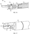
FIG. 14 , a cut away view of aclevis 330 is provided to show internal features ofclevis 330, includinggroove 340 formed in asidewall 336 ofclevis 330.Clevis 330 may further include anaperture 335 for a pin (not shown) to connect the jaws of an end effector and groove 340 may includesidewalls FIG. 14 , anend portion 306 of a push/pull drive element 300 may be placed withingroove 340 so thatgroove 340 supports and/or guidesend portion 306 as push/pull drive element 300 moves back and forth to actuate an end effector. In particular, the one or more surface portions ofend portion 306 may be in contact with one or more surfaces ofgroove 340. Turning toFIG. 15 , which is side view ofclevis 340 and push/pull drive element 300, with anend portion 306 of push/pull drive element 300 located withingroove 340,surface portions end portion 306 may engage one or both ofsidewalls groove 340 viacontact portions 350. According to an example,surface portions end portion 306 has one ormore surface portions contact portions 350 betweenend portion 306 andsidewalls groove 340 are not limited to point contacts or approximately tangential contacts, as discussed above in regard to the example ofFIG. 9 , but instead provide relatively large contact areas over which the forces exerted betweenend portion 306 and groove 340 may be distributed. As a result, the forces are not concentrated to a small area, which may lead to permanent deformation and/or increased wear rates. Further,end portions 306 of push/pull drive element 300 have enhanced resistance to the forces exerted when push/pull drive element 300 actuates an end effector and is subjected to twisting, as described above in regard to the example ofFIGS. 7 and 8 . - As described above with regard to the examples of
FIGS. 10-14 , push/pulldrive element 300 may include aninsulative material 308, particularly when push/pull drive element 300 is used in an energized surgical instrument. However, the examples described herein are not limited to energized surgical instruments and a push/pull drive element may be used in a non-energized surgical instrument. Turning toFIG. 16 , a cut-away view of a non-energizedsurgical instrument 400 is shown.Surgical instrument 400 may include ashaft 402,clevis 404,end effector 406, and a push/pull drive element 410.End effector 406 may includejaws pin 408 inserted through anaperture 405. Push/pull drive element 410 may be configured according to the examples ofFIGS. 10-15 except that push/pull drive element 410 does not includeinsulative material 308 becausesurgical instrument 400 is not energized. As shown inFIG. 17 , which shows a cut-away view ofclevis 404, push/pulldrive element 410 may include ashaft 412, one or more engagement portions 414 (such as, for example,engagement portions 414 provided by a cross shaft, as discussed above in regard toFIG. 11 ), and one ormore end portions 416.End portion 416 may be inserted within agroove 440 ofclevis 404, as discussed above in regard to the examples ofFIGS. 10-15 , so thatend portion 416 is guided and/or supported when push/pull drive element 410 moves back and forth to actuateend effector 406. - Due to the shape and size of end portions of a push/pull drive element as described in the examples of
FIGS. 10-17 , the amount of contact area between the end portions and a clevis groove is significantly increased. Thus, the end portions may advantageously enhance the distribution of force exerted between the end portions and grooves of a clevis. As a result, end portions of a push/pull drive element may counteract torque and a twisting motion applied to the push/pull drive element during actuation of an end effector, which may otherwise lead to deformation or wear of the clevis groove or the push/pull drive element popping out of the clevis groove. In particular, end portions of a push/pull drive element may minimize or reduce permanent deformation or wear of a groove of a clevis made of a non-metallic material, such as a plastic. - When a surgical instrument is energized, an electrical connection is provided between an end effector of the surgical instrument and one or more conduits providing electrical energy to the end effector. However, due to movements of the end effector, providing and maintaining a connection between the one or more conduits and the end effector may be difficult. Further, due to the small size of a surgical instrument and the limited about of space within a surgical instrument, the level of difficultly of providing a connection that is functional and durable is relatively high. For instance, an outer diameter of a surgical instrument may be, for example, approximately 5 mm.
- Turning to
FIG. 18 , an exemplary embodiment of asurgical instrument 500, according to the present invention, is shown that includesjaws pin 508, aclevis 506, and a push/pull drive element 510. Push/pull drive element 510 may be configured according to the examples ofFIGS. 10-17 . In this exemplary embodiment,surgical instrument 500 further includes aconnector assembly 530 to connect one ormore conduits jaws Conduits jaws jaws FIG. 19 showssurgical instrument 500 withjaw 504 removed so that components ofsurgical instrument 500 may be more easily viewed, such asconnector assembly 530.Surgical instrument 500 may further include a shaft (not shown) connected to clevis 506 and coveringconduits - When
jaws jaws surgical instrument 500. For instance,jaws direction 540 relative to pin 508, as shown in the exemplary embodiments ofFIGS. 18 and 19 . Due to the movement ofjaws conduits jaws conduits jaws conduits jaws jaws - Turning to
FIG. 20 , an exemplary embodiment of aconnector assembly 530 is shown, which includes abody 531.Connector assembly 530 provides a connection between one ormore conduits jaws more conduits connector assembly 530 provides an electrical connection between one ormore conduits body 531 is made of an electrically insulative material. For example,body 531 may be made of a plastic, such as, for example, a polyphthalamide (PPA) (e.g., Amodel®, which is sold by Solvay Advanced Polymers, L.L.C.).Body 531 may be used, for instance, to provide a structural support for a connection between one ormore conduits jaws surgical instrument 500 from the energy connected between the one ormore conduits jaws FIG. 20 ,body 531 is approximately U-shaped and may include afirst leg 532 and asecond leg 534. Further,legs gap 536, as shown in the exemplary embodiment ofFIG. 20 .Gap 536 may, for example, provide space for movement of push/pull drive element 510 withinbody 531, as shown in the exemplary embodiment ofFIG. 19 , such as when push/pull drive element 510 is moved to actuatejaws Body 531 further includes alumen 538 thatpin 508 may be inserted through, as shown in the exemplary embodiment ofFIGS. 18 and 19 . - According to an exemplary embodiment,
legs conduits leg 534 includes acavity 533 to receiveconduit 520, as shown in the exemplary embodiment ofFIG. 20 .Cavity 533 may be open, as shown in the exemplary embodiment ofFIG. 20 , or cavity may be at least partially covered.Conduit 520 may be received incavity 533 by, for example, insertingconduit 520 through anaperture 535 inleg 534.Leg 532 may be configured according to any of the above exemplary embodiments discussed forleg 534. - As shown in
FIG. 21 , which is an exploded view of the exemplary embodiment ofconnector assembly 530 ofFIG. 20 ,connector assembly 530 further includes one ormore connector portions 550. According to an exemplary embodiment,connector assembly 530 may include aconnector portion 550 for each conduit. For instance,connector assembly 530 may include aconnector portion 550 for each ofconduits FIG. 21 .Connector portions 550 may be attached tobody 531. As shown in the exemplary embodiment ofFIG. 21 ,connector portions 550 may be fit overprotuberances 537.Connector portions 550 may have a shape corresponding to the shape ofprotuberances 537. Further,connector portions 550 may be press fit toprotuberances 537, according to an exemplary embodiment. According to an exemplary embodiment,protuberances 537 may connect to clevis 506 to attachconnector assembly 530 andclevis 506. -
Connector portions 550 may include one or more structures to attach a conduit. Turning toFIG. 22 , which depicts an exemplary embodiment ofconduit 520 attached toconnector portion 550,connector portion 550 may include afirst attachment 553 and asecond attachment 552. Thesecond attachment 552 connectsconnector portion 550 toconduit 520. Whenconduit 520 includes more than one component, such as anouter insulative cover 523 and aconductor 521, as shown in the exemplary embodiment ofFIG. 22 ,second attachment 552 may connect to insulativecover 523 whilefirst attachment 553 connects to an exposed portion ofconductor 521. Thus,second attachment 552 may be provided, for example, to assist with maintaining a position ofconductor 520 relative toconnector portion 550, whilefirst attachment 553 is provided to form an electrically conductive contact betweenconnector portion 550 andconduit 520, particularlyconductor 521.Attachments conduit 520 via a mechanical connection, such as, for example, crimpingattachments conduit 520, via a bond, such as solder (e.g., solderingattachment 553 to conductor 521), or other joining method known to one of ordinary skill in the art.Conduit 522 may be connected toconnector portion 550 in the same way, according to an exemplary embodiment. -
Connector portions 550 may further include one or more structures to contact a portion of an end effector. For instance,connector portions 550 may include acontact portion 554 to contact at least one ofjaws Contact portion 554 may contact at least one ofjaws FIG. 18 ,jaw 504 may include anaperture 505 so thatjaw 504 may be fit overcontact portion 554. Further,aperture 505 may be structured to have a shape and size corresponding to contactportion 554 so that the portion ofjaw 504 formingaperture 505 is in contact withcontact portion 554. For instance,contact portions 554 may have a split ring shape, as shown in the exemplary embodiments ofFIGS. 19 ,21 , and22 . Thus, whenjaw 504 moves, such as by pivoting indirection 540 relative to pin 508,jaw 504 remains in contact withcontact portion 554.Jaw 502 may be configured according to the exemplary embodiments ofjaw 504 to also form a sliding contact with acontact portion 554 of aconnector assembly 530. By configuringcontact portions 554 ofconnectors 530 to contactjaws conduits jaws jaws jaws conduits - According to an exemplary embodiment,
connectors 530 may be configured so thatjaws contact portions 554. For instance, whenjaws jaws direction 540 aboutpin 508, as shown in the exemplary embodiment ofFIGS. 18 and 19 ,contact portion 554 remains substantially stationary asjaw 504 slides overcontact portion 554. As a result,conduits connectors 530 may also remain substantially stationary asjaws conduits conduits connectors 530. Further,conduits jaws connectors 530 form connections betweenconduits jaws - According to an exemplary embodiment, a
contact portion 554 may be connected to the one or more attachment(s) 552, 553 ofconnector portions 550 by abridge 556, as shown in the exemplary embodiment ofFIG. 22 . According to an exemplary embodiment,connector portions 550 may have a single piece construction. For instance, the one or more attachment(s) 552, 553,contact portion 554, and bridge 556 may be formed from a single piece, although the exemplary embodiments ofconnector portions 550 described herein are not limited to a single piece construction. - According to an exemplary embodiment,
connection portions 550 may be made of a conductive material, such as an electrically conductive material, so that energy provided byconduits jaws connector portions 550. For example,connection portions 550 may be made of a metal, such as, for example, a stainless steel. - By providing a surgical instrument with a push/pull drive element according to the exemplary embodiments described herein, a connection may be advantageously provided between the push/pull drive element and a component of the surgical instrument that has enhanced durability while permitting push/pull drive element to move and actuate an end effector of the surgical instrument. Further, by providing a connector that permits sliding contact and/or independent movement between an end effector and the connector, a connection may be advantageously provided between one or more conduits and the end effector that is durable, while permitting movement of the end effector and providing energy to the end effector from the one or more conduit(s).
- Further modifications and alternative embodiments will be apparent to those of ordinary skill in the art in view of the disclosure herein. For example, the systems and the methods may include additional components or steps that were omitted from the diagrams and description for clarity of operation. Accordingly, this description is to be construed as illustrative only and is for the purpose of teaching those skilled in the art the general manner of carrying out the present teachings. It is to be understood that the various embodiments shown and described herein are to be taken as exemplary. Elements and materials, and arrangements of those elements and materials, may be substituted for those illustrated and described herein, parts and processes may be reversed, and certain features of the present teachings may be utilized independently, all as would be apparent to one skilled in the art after having the benefit of the description herein. Changes may be made in the elements described herein without departing from the scope of the following claims.
- It is to be understood that the particular examples and embodiments set forth herein are nonlimiting, and modifications to structure, dimensions, materials, and methodologies may be made without departing from the scope of the present disclosure and claims.
- Other embodiments in accordance with the present disclosure will be apparent to those skilled in the art from consideration of the specification and practice of the present disclosure and claims. It is intended that the specification and examples be considered as exemplary only, with the claims being entitled to their full scope.
Claims (7)
- A surgical instrument (500) comprising:a connector assembly (530), a jaw (502,504), an electrical transmission conduit (520,522), a clevis (506), and a shaft (122,202,402);wherein:the connector assembly (530) comprises:a U-shaped electrically insulative body (531) comprising a leg (532,534), a cavity (533) defined in the leg, a protuberance (537), and a lumen (538) defined through the protuberance; andan electrical connector (550) comprising an electrical attachment (553) positioned in the cavity (533) of the electrically insulative body (531) and an electrical contact portion (554) fitted over the protuberance (537) of the electrically insulative body;the jaw (502, 504) comprises an aperture (505), the jaw being fitted over the protuberance (537) of the electrically insulative body (531) and over the electrical contact portion (554) of the electrical connector (550) such that sliding electrical contact is established at the aperture between the electrical contact portion and the jaw;the electrical transmission conduit (520, 522) is electrically connected to the electrical attachment (553) of the electrical connector (550);the clevis (506) comprises a pin (508), the pin extending through the lumen (538) of the electrically insulative body (531) and the aperture (505) of the jaw (502, 504); andthe shaft (122, 202, 402) is coupled to the clevis (506), the shaft covering the electrical transmission conduit (520, 522).
- The surgical instrument (500) claimed in claim 1, wherein the electrical contact portion (554) of the electrical connector (550) comprises a ring fitted around the protuberance (537).
- The surgical instrument (500) claimed in claim 1 or claim 2, wherein the electrical connector (550) comprises an electrically conductive bridge (556) between the electrical attachment (553) and the electrical contact portion (554).
- The surgical instrument (500) claimed in any one of the preceding claims, wherein the electrical connector (550) comprises a second attachment (552), and the electrical transmission conduit (520, 522) is non-electrically connected to the second attachment.
- The surgical instrument (500) claimed in any one of the preceding claims, further comprising:a drive element (510);wherein the electrically insulative body (531) comprises a pair of said legs (532,534), the jaw comprises an actuation aperture, and the drive element (510) is positioned between the legs (532, 534) and extends into the actuation aperture.
- The surgical instrument (500) claimed in any one of the preceding claims, further comprising:a second jaw (502, 504) comprising a second aperture; anda second electrical transmission conduit (520, 522);the electrically insulative body (531) of the connector assembly (530) comprising a second protuberance (537), the lumen (538) of the body being further defined through the second protuberance;the connector assembly (530) comprising a second electrical connector (550), the second electrical connector comprising a second electrical attachment (553) and a second electrical contact portion (554) fitted over the second protuberance (537);the second jaw (502, 504) being fitted over the second protuberance (537) of the electrically insulative body (531) and over the second electrical contact portion (554) of the second electrical connector (550) such that sliding electrical contact is established at the second aperture between the second electrical contact portion (554) and the second jaw (502, 504);the second electrical transmission conduit (520, 522) being electrically connected to the second electrical attachment (553) of the second electrical connector (550);the pin (508) further extending through the second aperture of the second jaw (502, 504); andthe shaft (122, 202, 402) covering the second electrical transmission conduit (520, 522).
- The surgical instrument claimed in claim 6, wherein the electrically insulative body (531) is located between the jaw (502, 504) and the second jaw (502, 504).
Applications Claiming Priority (3)
| Application Number | Priority Date | Filing Date | Title |
|---|---|---|---|
| US201361803046P | 2013-03-18 | 2013-03-18 | |
| PCT/US2014/026137 WO2014151633A1 (en) | 2013-03-18 | 2014-03-13 | Surgical instrument drive element, and related devices, systems, and methods |
| EP14768826.1A EP2976026B1 (en) | 2013-03-18 | 2014-03-13 | Surgical instrument drive element, related devices and systems |
Related Parent Applications (2)
| Application Number | Title | Priority Date | Filing Date |
|---|---|---|---|
| EP14768826.1A Division-Into EP2976026B1 (en) | 2013-03-18 | 2014-03-13 | Surgical instrument drive element, related devices and systems |
| EP14768826.1A Division EP2976026B1 (en) | 2013-03-18 | 2014-03-13 | Surgical instrument drive element, related devices and systems |
Publications (2)
| Publication Number | Publication Date |
|---|---|
| EP3488807A1 EP3488807A1 (en) | 2019-05-29 |
| EP3488807B1 true EP3488807B1 (en) | 2020-09-09 |
Family
ID=51531098
Family Applications (2)
| Application Number | Title | Priority Date | Filing Date |
|---|---|---|---|
| EP14768826.1A Active EP2976026B1 (en) | 2013-03-18 | 2014-03-13 | Surgical instrument drive element, related devices and systems |
| EP19151045.2A Active EP3488807B1 (en) | 2013-03-18 | 2014-03-13 | Surgical instrument drive element, related devices and systems |
Family Applications Before (1)
| Application Number | Title | Priority Date | Filing Date |
|---|---|---|---|
| EP14768826.1A Active EP2976026B1 (en) | 2013-03-18 | 2014-03-13 | Surgical instrument drive element, related devices and systems |
Country Status (6)
| Country | Link |
|---|---|
| US (4) | US9498242B2 (en) |
| EP (2) | EP2976026B1 (en) |
| JP (4) | JP6383780B2 (en) |
| KR (1) | KR102256358B1 (en) |
| CN (3) | CN108113756B (en) |
| WO (1) | WO2014151633A1 (en) |
Families Citing this family (14)
| Publication number | Priority date | Publication date | Assignee | Title |
|---|---|---|---|---|
| US9498242B2 (en) | 2013-03-18 | 2016-11-22 | Inuitive Surgical Operations, Inc. | Surgical instrument drive element, and related devices, systems, and methods |
| ITUB20154977A1 (en) | 2015-10-16 | 2017-04-16 | Medical Microinstruments S R L | Medical instrument and method of manufacture of said medical instrument |
| CN108289691B (en) * | 2015-11-13 | 2021-04-09 | 直观外科手术操作公司 | Push-pull type stitching instrument with two-degree-of-freedom wrist |
| NL2017630B1 (en) * | 2016-10-17 | 2018-04-24 | Surge On Medical B V | A surgical device |
| US11364067B2 (en) * | 2017-10-06 | 2022-06-21 | Cilag Gmbh International | Electrical isolation of electrosurgical instruments |
| EP3727140B1 (en) | 2017-12-22 | 2023-11-01 | Briteseed, LLC | A compact system used to determine tissue or artifact characteristics |
| PL3578118T3 (en) | 2018-06-05 | 2022-11-21 | Erbe Elektromedizin Gmbh | Surgical instrument |
| WO2020018371A1 (en) * | 2018-07-17 | 2020-01-23 | Intuitive Surgical Operations, Inc. | Surgical instruments with reduced capacitance, related devices, and related methods |
| USD904611S1 (en) | 2018-10-10 | 2020-12-08 | Bolder Surgical, Llc | Jaw design for a surgical instrument |
| CN113164183A (en) * | 2018-11-30 | 2021-07-23 | 奥林巴斯株式会社 | Grasping mechanism |
| CN113194847A (en) * | 2018-12-21 | 2021-07-30 | 直观外科手术操作公司 | Actuation mechanism for a surgical instrument |
| WO2021136004A1 (en) * | 2019-12-30 | 2021-07-08 | 北京术锐技术有限公司 | Surgical effector, surgical tool and surgical robot |
| DE102021201311A1 (en) * | 2021-02-11 | 2022-08-11 | Aesculap Ag | Surgical instrument, tooling for such a surgical instrument and method for manufacturing such a tooling |
| GB2611346A (en) * | 2021-10-01 | 2023-04-05 | Cmr Surgical Ltd | A robotic surgical instrument |
Family Cites Families (32)
| Publication number | Priority date | Publication date | Assignee | Title |
|---|---|---|---|---|
| JPS60107291U (en) * | 1983-12-27 | 1985-07-22 | 株式会社 ニチベイ | roll screen |
| US5396900A (en) | 1991-04-04 | 1995-03-14 | Symbiosis Corporation | Endoscopic end effectors constructed from a combination of conductive and non-conductive materials and useful for selective endoscopic cautery |
| CA2159348A1 (en) * | 1993-04-30 | 1994-11-10 | Claude A. Vidal | Surgical instrument having an articulated jaw structure and a detachable knife |
| US5395369A (en) * | 1993-06-10 | 1995-03-07 | Symbiosis Corporation | Endoscopic bipolar electrocautery instruments |
| US5782749A (en) * | 1994-05-10 | 1998-07-21 | Riza; Erol D. | Laparoscopic surgical instrument with adjustable grip |
| WO1996002193A1 (en) * | 1994-07-14 | 1996-02-01 | Symbiosis Corporation | Track guided end effector assembly |
| US5478350A (en) * | 1994-07-14 | 1995-12-26 | Symbiosis Corporation | Rack and pinion actuator handle for endoscopic instruments |
| US5695511A (en) * | 1994-11-29 | 1997-12-09 | Metamorphic Surgical Devices | Surgical instruments for minimally invasive procedures |
| US5904702A (en) * | 1997-08-14 | 1999-05-18 | University Of Massachusetts | Instrument for thoracic surgical procedures |
| US6139563A (en) * | 1997-09-25 | 2000-10-31 | Allegiance Corporation | Surgical device with malleable shaft |
| US5919206A (en) * | 1998-02-20 | 1999-07-06 | C. M. Wright, Inc. | Surgical tool |
| US6193718B1 (en) * | 1998-06-10 | 2001-02-27 | Scimed Life Systems, Inc. | Endoscopic electrocautery instrument |
| US20040249374A1 (en) * | 1998-10-23 | 2004-12-09 | Tetzlaff Philip M. | Vessel sealing instrument |
| DE60115295T2 (en) | 2001-04-06 | 2006-08-10 | Sherwood Services Ag | VASILY DEVICE |
| US6733514B2 (en) * | 2001-10-05 | 2004-05-11 | Pilling Weck Incorporated | Jaw assembly for endoscopic instruments |
| DE202004010780U1 (en) * | 2004-07-02 | 2004-09-09 | Karl Storz Gmbh & Co. Kg | Medical instrument for electrosurgery |
| US7918848B2 (en) | 2005-03-25 | 2011-04-05 | Maquet Cardiovascular, Llc | Tissue welding and cutting apparatus and method |
| US8197472B2 (en) | 2005-03-25 | 2012-06-12 | Maquet Cardiovascular, Llc | Tissue welding and cutting apparatus and method |
| US8771270B2 (en) | 2008-07-16 | 2014-07-08 | Intuitive Surgical Operations, Inc. | Bipolar cautery instrument |
| US8968355B2 (en) | 2008-08-04 | 2015-03-03 | Covidien Lp | Articulating surgical device |
| US8409200B2 (en) * | 2008-09-03 | 2013-04-02 | Ethicon Endo-Surgery, Inc. | Surgical grasping device |
| CN102264307A (en) * | 2008-12-12 | 2011-11-30 | 伊顿株式会社 | Surgical instrument |
| US8333780B1 (en) * | 2009-06-05 | 2012-12-18 | Okay Industries, Inc. | Surgical tool and method of operation |
| WO2011033860A1 (en) | 2009-09-15 | 2011-03-24 | オリンパスメディカルシステムズ株式会社 | Treatment instrument for endoscope |
| US8551115B2 (en) | 2009-09-23 | 2013-10-08 | Intuitive Surgical Operations, Inc. | Curved cannula instrument |
| US9339341B2 (en) * | 2010-02-08 | 2016-05-17 | Intuitive Surgical Operations, Inc. | Direct pull surgical gripper |
| RO126740A2 (en) * | 2010-04-02 | 2011-10-28 | Cătălin Eşanu | Endoscopic surgery instrument with detachable clamp, clamp-extractor and method for using the same |
| CN201752400U (en) * | 2010-06-25 | 2011-03-02 | 深圳市第二人民医院 | Uterine cavity examination resection hysteroscopy |
| JP5704858B2 (en) | 2010-08-24 | 2015-04-22 | Hoya株式会社 | Endoscopy forceps |
| WO2014008492A1 (en) * | 2012-07-06 | 2014-01-09 | Intuitive Surgical Operations, Inc. | Remotely actuated surgical gripper with seize resistance |
| CA2987233C (en) * | 2013-02-07 | 2019-10-29 | Teleflex Medical Incorporated | End effector connection and actuation systems |
| US9498242B2 (en) | 2013-03-18 | 2016-11-22 | Inuitive Surgical Operations, Inc. | Surgical instrument drive element, and related devices, systems, and methods |
-
2014
- 2014-03-13 US US14/209,043 patent/US9498242B2/en active Active
- 2014-03-13 WO PCT/US2014/026137 patent/WO2014151633A1/en active Application Filing
- 2014-03-13 CN CN201711154054.3A patent/CN108113756B/en active Active
- 2014-03-13 CN CN201480016495.5A patent/CN105188572B/en active Active
- 2014-03-13 KR KR1020157029608A patent/KR102256358B1/en active IP Right Grant
- 2014-03-13 CN CN202110773839.9A patent/CN113331951A/en active Pending
- 2014-03-13 JP JP2016504313A patent/JP6383780B2/en active Active
- 2014-03-13 EP EP14768826.1A patent/EP2976026B1/en active Active
- 2014-03-13 EP EP19151045.2A patent/EP3488807B1/en active Active
-
2016
- 2016-11-10 US US15/348,127 patent/US10716617B2/en active Active
-
2018
- 2018-08-06 JP JP2018147890A patent/JP6708710B2/en active Active
-
2020
- 2020-05-21 JP JP2020088721A patent/JP7019747B2/en active Active
- 2020-07-01 US US16/918,026 patent/US11564734B2/en active Active
-
2022
- 2022-02-02 JP JP2022014842A patent/JP7286818B2/en active Active
- 2022-12-29 US US18/148,136 patent/US20230210584A1/en active Pending
Non-Patent Citations (1)
| Title |
|---|
| None * |
Also Published As
| Publication number | Publication date |
|---|---|
| EP2976026B1 (en) | 2019-02-27 |
| CN105188572A (en) | 2015-12-23 |
| CN108113756A (en) | 2018-06-05 |
| JP2018164829A (en) | 2018-10-25 |
| CN105188572B (en) | 2017-12-26 |
| JP6383780B2 (en) | 2018-08-29 |
| JP7019747B2 (en) | 2022-02-15 |
| JP7286818B2 (en) | 2023-06-05 |
| US20140277106A1 (en) | 2014-09-18 |
| US20170056098A1 (en) | 2017-03-02 |
| JP2022048308A (en) | 2022-03-25 |
| JP6708710B2 (en) | 2020-06-10 |
| JP2020146477A (en) | 2020-09-17 |
| WO2014151633A1 (en) | 2014-09-25 |
| EP3488807A1 (en) | 2019-05-29 |
| CN108113756B (en) | 2021-07-30 |
| US11564734B2 (en) | 2023-01-31 |
| US9498242B2 (en) | 2016-11-22 |
| US10716617B2 (en) | 2020-07-21 |
| EP2976026A4 (en) | 2016-11-09 |
| US20200397502A1 (en) | 2020-12-24 |
| CN113331951A (en) | 2021-09-03 |
| EP2976026A1 (en) | 2016-01-27 |
| JP2016518171A (en) | 2016-06-23 |
| KR20150127284A (en) | 2015-11-16 |
| KR102256358B1 (en) | 2021-05-27 |
| US20230210584A1 (en) | 2023-07-06 |
Similar Documents
| Publication | Publication Date | Title |
|---|---|---|
| US11564734B2 (en) | Surgical instrument drive element, and related devices, systems, and methods | |
| EP2996620B1 (en) | Force transmission mechanism for teleoperated surgical system | |
| US11712288B2 (en) | Bipolar end effector apparatus for a surgical instrument | |
| KR102006471B1 (en) | Bipolar cautery instrument | |
| KR102330042B1 (en) | medical instrument with tension band | |
| JP2010142279A (en) | Treatment instrument |
Legal Events
| Date | Code | Title | Description |
|---|---|---|---|
| PUAI | Public reference made under article 153(3) epc to a published international application that has entered the european phase |
Free format text: ORIGINAL CODE: 0009012 |
|
| STAA | Information on the status of an ep patent application or granted ep patent |
Free format text: STATUS: THE APPLICATION HAS BEEN PUBLISHED |
|
| AC | Divisional application: reference to earlier application |
Ref document number: 2976026 Country of ref document: EP Kind code of ref document: P |
|
| AK | Designated contracting states |
Kind code of ref document: A1 Designated state(s): AL AT BE BG CH CY CZ DE DK EE ES FI FR GB GR HR HU IE IS IT LI LT LU LV MC MK MT NL NO PL PT RO RS SE SI SK SM TR |
|
| STAA | Information on the status of an ep patent application or granted ep patent |
Free format text: STATUS: REQUEST FOR EXAMINATION WAS MADE |
|
| 17P | Request for examination filed |
Effective date: 20191128 |
|
| RBV | Designated contracting states (corrected) |
Designated state(s): AL AT BE BG CH CY CZ DE DK EE ES FI FR GB GR HR HU IE IS IT LI LT LU LV MC MK MT NL NO PL PT RO RS SE SI SK SM TR |
|
| REG | Reference to a national code |
Ref country code: DE Ref legal event code: R079 Ref document number: 602014070167 Country of ref document: DE Free format text: PREVIOUS MAIN CLASS: A61B0018140000 Ipc: A61B0017290000 |
|
| GRAP | Despatch of communication of intention to grant a patent |
Free format text: ORIGINAL CODE: EPIDOSNIGR1 |
|
| STAA | Information on the status of an ep patent application or granted ep patent |
Free format text: STATUS: GRANT OF PATENT IS INTENDED |
|
| RIC1 | Information provided on ipc code assigned before grant |
Ipc: A61B 18/14 20060101ALI20200311BHEP Ipc: A61B 34/30 20160101ALI20200311BHEP Ipc: A61B 17/29 20060101AFI20200311BHEP |
|
| INTG | Intention to grant announced |
Effective date: 20200330 |
|
| GRAS | Grant fee paid |
Free format text: ORIGINAL CODE: EPIDOSNIGR3 |
|
| GRAA | (expected) grant |
Free format text: ORIGINAL CODE: 0009210 |
|
| STAA | Information on the status of an ep patent application or granted ep patent |
Free format text: STATUS: THE PATENT HAS BEEN GRANTED |
|
| AC | Divisional application: reference to earlier application |
Ref document number: 2976026 Country of ref document: EP Kind code of ref document: P |
|
| AK | Designated contracting states |
Kind code of ref document: B1 Designated state(s): AL AT BE BG CH CY CZ DE DK EE ES FI FR GB GR HR HU IE IS IT LI LT LU LV MC MK MT NL NO PL PT RO RS SE SI SK SM TR |
|
| REG | Reference to a national code |
Ref country code: GB Ref legal event code: FG4D |
|
| REG | Reference to a national code |
Ref country code: AT Ref legal event code: REF Ref document number: 1310582 Country of ref document: AT Kind code of ref document: T Effective date: 20200915 Ref country code: CH Ref legal event code: EP |
|
| REG | Reference to a national code |
Ref country code: DE Ref legal event code: R096 Ref document number: 602014070167 Country of ref document: DE |
|
| REG | Reference to a national code |
Ref country code: IE Ref legal event code: FG4D |
|
| REG | Reference to a national code |
Ref country code: LT Ref legal event code: MG4D |
|
| PG25 | Lapsed in a contracting state [announced via postgrant information from national office to epo] |
Ref country code: FI Free format text: LAPSE BECAUSE OF FAILURE TO SUBMIT A TRANSLATION OF THE DESCRIPTION OR TO PAY THE FEE WITHIN THE PRESCRIBED TIME-LIMIT Effective date: 20200909 Ref country code: SE Free format text: LAPSE BECAUSE OF FAILURE TO SUBMIT A TRANSLATION OF THE DESCRIPTION OR TO PAY THE FEE WITHIN THE PRESCRIBED TIME-LIMIT Effective date: 20200909 Ref country code: NO Free format text: LAPSE BECAUSE OF FAILURE TO SUBMIT A TRANSLATION OF THE DESCRIPTION OR TO PAY THE FEE WITHIN THE PRESCRIBED TIME-LIMIT Effective date: 20201209 Ref country code: HR Free format text: LAPSE BECAUSE OF FAILURE TO SUBMIT A TRANSLATION OF THE DESCRIPTION OR TO PAY THE FEE WITHIN THE PRESCRIBED TIME-LIMIT Effective date: 20200909 Ref country code: GR Free format text: LAPSE BECAUSE OF FAILURE TO SUBMIT A TRANSLATION OF THE DESCRIPTION OR TO PAY THE FEE WITHIN THE PRESCRIBED TIME-LIMIT Effective date: 20201210 Ref country code: LT Free format text: LAPSE BECAUSE OF FAILURE TO SUBMIT A TRANSLATION OF THE DESCRIPTION OR TO PAY THE FEE WITHIN THE PRESCRIBED TIME-LIMIT Effective date: 20200909 Ref country code: BG Free format text: LAPSE BECAUSE OF FAILURE TO SUBMIT A TRANSLATION OF THE DESCRIPTION OR TO PAY THE FEE WITHIN THE PRESCRIBED TIME-LIMIT Effective date: 20201209 |
|
| REG | Reference to a national code |
Ref country code: AT Ref legal event code: MK05 Ref document number: 1310582 Country of ref document: AT Kind code of ref document: T Effective date: 20200909 |
|
| REG | Reference to a national code |
Ref country code: NL Ref legal event code: MP Effective date: 20200909 |
|
| PG25 | Lapsed in a contracting state [announced via postgrant information from national office to epo] |
Ref country code: PL Free format text: LAPSE BECAUSE OF FAILURE TO SUBMIT A TRANSLATION OF THE DESCRIPTION OR TO PAY THE FEE WITHIN THE PRESCRIBED TIME-LIMIT Effective date: 20200909 Ref country code: LV Free format text: LAPSE BECAUSE OF FAILURE TO SUBMIT A TRANSLATION OF THE DESCRIPTION OR TO PAY THE FEE WITHIN THE PRESCRIBED TIME-LIMIT Effective date: 20200909 Ref country code: RS Free format text: LAPSE BECAUSE OF FAILURE TO SUBMIT A TRANSLATION OF THE DESCRIPTION OR TO PAY THE FEE WITHIN THE PRESCRIBED TIME-LIMIT Effective date: 20200909 |
|
| PG25 | Lapsed in a contracting state [announced via postgrant information from national office to epo] |
Ref country code: SM Free format text: LAPSE BECAUSE OF FAILURE TO SUBMIT A TRANSLATION OF THE DESCRIPTION OR TO PAY THE FEE WITHIN THE PRESCRIBED TIME-LIMIT Effective date: 20200909 Ref country code: CZ Free format text: LAPSE BECAUSE OF FAILURE TO SUBMIT A TRANSLATION OF THE DESCRIPTION OR TO PAY THE FEE WITHIN THE PRESCRIBED TIME-LIMIT Effective date: 20200909 Ref country code: RO Free format text: LAPSE BECAUSE OF FAILURE TO SUBMIT A TRANSLATION OF THE DESCRIPTION OR TO PAY THE FEE WITHIN THE PRESCRIBED TIME-LIMIT Effective date: 20200909 Ref country code: PT Free format text: LAPSE BECAUSE OF FAILURE TO SUBMIT A TRANSLATION OF THE DESCRIPTION OR TO PAY THE FEE WITHIN THE PRESCRIBED TIME-LIMIT Effective date: 20210111 Ref country code: EE Free format text: LAPSE BECAUSE OF FAILURE TO SUBMIT A TRANSLATION OF THE DESCRIPTION OR TO PAY THE FEE WITHIN THE PRESCRIBED TIME-LIMIT Effective date: 20200909 |
|
| PG25 | Lapsed in a contracting state [announced via postgrant information from national office to epo] |
Ref country code: AL Free format text: LAPSE BECAUSE OF FAILURE TO SUBMIT A TRANSLATION OF THE DESCRIPTION OR TO PAY THE FEE WITHIN THE PRESCRIBED TIME-LIMIT Effective date: 20200909 Ref country code: AT Free format text: LAPSE BECAUSE OF FAILURE TO SUBMIT A TRANSLATION OF THE DESCRIPTION OR TO PAY THE FEE WITHIN THE PRESCRIBED TIME-LIMIT Effective date: 20200909 Ref country code: ES Free format text: LAPSE BECAUSE OF FAILURE TO SUBMIT A TRANSLATION OF THE DESCRIPTION OR TO PAY THE FEE WITHIN THE PRESCRIBED TIME-LIMIT Effective date: 20200909 Ref country code: IS Free format text: LAPSE BECAUSE OF FAILURE TO SUBMIT A TRANSLATION OF THE DESCRIPTION OR TO PAY THE FEE WITHIN THE PRESCRIBED TIME-LIMIT Effective date: 20210109 |
|
| REG | Reference to a national code |
Ref country code: DE Ref legal event code: R097 Ref document number: 602014070167 Country of ref document: DE |
|
| PG25 | Lapsed in a contracting state [announced via postgrant information from national office to epo] |
Ref country code: SK Free format text: LAPSE BECAUSE OF FAILURE TO SUBMIT A TRANSLATION OF THE DESCRIPTION OR TO PAY THE FEE WITHIN THE PRESCRIBED TIME-LIMIT Effective date: 20200909 |
|
| PLBE | No opposition filed within time limit |
Free format text: ORIGINAL CODE: 0009261 |
|
| STAA | Information on the status of an ep patent application or granted ep patent |
Free format text: STATUS: NO OPPOSITION FILED WITHIN TIME LIMIT |
|
| 26N | No opposition filed |
Effective date: 20210610 |
|
| PG25 | Lapsed in a contracting state [announced via postgrant information from national office to epo] |
Ref country code: DK Free format text: LAPSE BECAUSE OF FAILURE TO SUBMIT A TRANSLATION OF THE DESCRIPTION OR TO PAY THE FEE WITHIN THE PRESCRIBED TIME-LIMIT Effective date: 20200909 Ref country code: SI Free format text: LAPSE BECAUSE OF FAILURE TO SUBMIT A TRANSLATION OF THE DESCRIPTION OR TO PAY THE FEE WITHIN THE PRESCRIBED TIME-LIMIT Effective date: 20200909 |
|
| PG25 | Lapsed in a contracting state [announced via postgrant information from national office to epo] |
Ref country code: MC Free format text: LAPSE BECAUSE OF FAILURE TO SUBMIT A TRANSLATION OF THE DESCRIPTION OR TO PAY THE FEE WITHIN THE PRESCRIBED TIME-LIMIT Effective date: 20200909 Ref country code: IT Free format text: LAPSE BECAUSE OF FAILURE TO SUBMIT A TRANSLATION OF THE DESCRIPTION OR TO PAY THE FEE WITHIN THE PRESCRIBED TIME-LIMIT Effective date: 20200909 |
|
| REG | Reference to a national code |
Ref country code: CH Ref legal event code: PL |
|
| GBPC | Gb: european patent ceased through non-payment of renewal fee |
Effective date: 20210313 |
|
| REG | Reference to a national code |
Ref country code: BE Ref legal event code: MM Effective date: 20210331 |
|
| PG25 | Lapsed in a contracting state [announced via postgrant information from national office to epo] |
Ref country code: FR Free format text: LAPSE BECAUSE OF NON-PAYMENT OF DUE FEES Effective date: 20210331 Ref country code: GB Free format text: LAPSE BECAUSE OF NON-PAYMENT OF DUE FEES Effective date: 20210313 Ref country code: CH Free format text: LAPSE BECAUSE OF NON-PAYMENT OF DUE FEES Effective date: 20210331 Ref country code: LI Free format text: LAPSE BECAUSE OF NON-PAYMENT OF DUE FEES Effective date: 20210331 Ref country code: LU Free format text: LAPSE BECAUSE OF NON-PAYMENT OF DUE FEES Effective date: 20210313 Ref country code: IE Free format text: LAPSE BECAUSE OF NON-PAYMENT OF DUE FEES Effective date: 20210313 |
|
| PG25 | Lapsed in a contracting state [announced via postgrant information from national office to epo] |
Ref country code: BE Free format text: LAPSE BECAUSE OF NON-PAYMENT OF DUE FEES Effective date: 20210331 |
|
| PGFP | Annual fee paid to national office [announced via postgrant information from national office to epo] |
Ref country code: DE Payment date: 20230328 Year of fee payment: 10 |
|
| P01 | Opt-out of the competence of the unified patent court (upc) registered |
Effective date: 20230330 |
|
| PG25 | Lapsed in a contracting state [announced via postgrant information from national office to epo] |
Ref country code: CY Free format text: LAPSE BECAUSE OF FAILURE TO SUBMIT A TRANSLATION OF THE DESCRIPTION OR TO PAY THE FEE WITHIN THE PRESCRIBED TIME-LIMIT Effective date: 20200909 Ref country code: NL Free format text: LAPSE BECAUSE OF NON-PAYMENT OF DUE FEES Effective date: 20200923 |
|
| PG25 | Lapsed in a contracting state [announced via postgrant information from national office to epo] |
Ref country code: HU Free format text: LAPSE BECAUSE OF FAILURE TO SUBMIT A TRANSLATION OF THE DESCRIPTION OR TO PAY THE FEE WITHIN THE PRESCRIBED TIME-LIMIT; INVALID AB INITIO Effective date: 20140313 |