EP3488743B1 - Mixer mit doppelter antriebsfunktion auf einer welle - Google Patents
Mixer mit doppelter antriebsfunktion auf einer welle Download PDFInfo
- Publication number
- EP3488743B1 EP3488743B1 EP18207517.6A EP18207517A EP3488743B1 EP 3488743 B1 EP3488743 B1 EP 3488743B1 EP 18207517 A EP18207517 A EP 18207517A EP 3488743 B1 EP3488743 B1 EP 3488743B1
- Authority
- EP
- European Patent Office
- Prior art keywords
- coupling device
- mixer
- jug
- base
- shaped attachment
- Prior art date
- Legal status (The legal status is an assumption and is not a legal conclusion. Google has not performed a legal analysis and makes no representation as to the accuracy of the status listed.)
- Active
Links
Images


Classifications
-
- A—HUMAN NECESSITIES
- A47—FURNITURE; DOMESTIC ARTICLES OR APPLIANCES; COFFEE MILLS; SPICE MILLS; SUCTION CLEANERS IN GENERAL
- A47J—KITCHEN EQUIPMENT; COFFEE MILLS; SPICE MILLS; APPARATUS FOR MAKING BEVERAGES
- A47J43/00—Implements for preparing or holding food, not provided for in other groups of this subclass
- A47J43/04—Machines for domestic use not covered elsewhere, e.g. for grinding, mixing, stirring, kneading, emulsifying, whipping or beating foodstuffs, e.g. power-driven
- A47J43/046—Machines for domestic use not covered elsewhere, e.g. for grinding, mixing, stirring, kneading, emulsifying, whipping or beating foodstuffs, e.g. power-driven with tools driven from the bottom side
-
- A—HUMAN NECESSITIES
- A47—FURNITURE; DOMESTIC ARTICLES OR APPLIANCES; COFFEE MILLS; SPICE MILLS; SUCTION CLEANERS IN GENERAL
- A47J—KITCHEN EQUIPMENT; COFFEE MILLS; SPICE MILLS; APPARATUS FOR MAKING BEVERAGES
- A47J43/00—Implements for preparing or holding food, not provided for in other groups of this subclass
- A47J43/04—Machines for domestic use not covered elsewhere, e.g. for grinding, mixing, stirring, kneading, emulsifying, whipping or beating foodstuffs, e.g. power-driven
- A47J43/06—Machines for domestic use not covered elsewhere, e.g. for grinding, mixing, stirring, kneading, emulsifying, whipping or beating foodstuffs, e.g. power-driven with a plurality of interchangeable working units, e.g. with a single driving-unit
-
- A—HUMAN NECESSITIES
- A47—FURNITURE; DOMESTIC ARTICLES OR APPLIANCES; COFFEE MILLS; SPICE MILLS; SUCTION CLEANERS IN GENERAL
- A47J—KITCHEN EQUIPMENT; COFFEE MILLS; SPICE MILLS; APPARATUS FOR MAKING BEVERAGES
- A47J43/00—Implements for preparing or holding food, not provided for in other groups of this subclass
- A47J43/04—Machines for domestic use not covered elsewhere, e.g. for grinding, mixing, stirring, kneading, emulsifying, whipping or beating foodstuffs, e.g. power-driven
- A47J43/07—Parts or details, e.g. mixing tools, whipping tools
- A47J43/0716—Parts or details, e.g. mixing tools, whipping tools for machines with tools driven from the lower side
-
- A—HUMAN NECESSITIES
- A47—FURNITURE; DOMESTIC ARTICLES OR APPLIANCES; COFFEE MILLS; SPICE MILLS; SUCTION CLEANERS IN GENERAL
- A47J—KITCHEN EQUIPMENT; COFFEE MILLS; SPICE MILLS; APPARATUS FOR MAKING BEVERAGES
- A47J43/00—Implements for preparing or holding food, not provided for in other groups of this subclass
- A47J43/04—Machines for domestic use not covered elsewhere, e.g. for grinding, mixing, stirring, kneading, emulsifying, whipping or beating foodstuffs, e.g. power-driven
- A47J43/07—Parts or details, e.g. mixing tools, whipping tools
- A47J43/08—Driving mechanisms
- A47J43/085—Driving mechanisms for machines with tools driven from the lower side
Definitions
- the invention relates to a mixer, in particular for mixing food in normal household quantities, comprising a mixer base in which at least one drive motor is arranged, and a jug-shaped attachment which has a rotating tool, the mixer base and the jug-shaped attachment being designed to be separable from one another, and wherein at least one drive shaft of the drive motor is led out of the mixer base and has a first coupling device for a corresponding first counter-coupling device on the bottom of the jug-shaped attachment.
- the invention also relates to a mixer base for a jug-shaped attachment that can be attached to and detached from the mixer base.
- the invention relates to a jug-shaped attachment for releasable attachment to a mixer base.
- a special case is given if a dish is to be stirred or mixed for a longer period and at the same time additional ingredients are to be added to the stirred or mixed dish while grinding.
- An example is the production of ice cream from water ice and an ice cream mixture, or from frozen fruits and egg whites, in which grated chocolate is to be placed, or a risotto that has to be stirred in the heat for a long time and in which vegetables are chopped up at the same time or mushrooms are to be introduced.
- a stirrer or mixer arranged on a common shaft and a cutting disk would always have to be rotated at the same speed of rotation. Mixing and cutting generally require different speeds of rotation, so that the simultaneous use of mixing and cutting on a common shaft is not possible in many cases or leads to undesirable results.
- the object of the invention is therefore to provide an improved mixer.
- a mixer is to be made available with which it is possible to stir or mix at the same time and to chop up food.
- the invention is also based on the object of providing an improved mixer base and an improved jug-shaped attachment for a mixer.
- a mixer mentioned at the beginning, in which it is provided that a second coupling device for a corresponding second counter-coupling device of the jug-shaped extension is arranged on the mixer base.
- jug-shaped means that the attachment is designed as a vessel that is open at the top.
- the object of the invention is also provided by a mixer base for a jug-shaped attachment that can be attached to and detached from the mixer base, which has a rotating first tool inside, in particular for mixing food in normal household quantities, with at least one drive motor being arranged in the mixer base, at least a drive shaft of the drive motor is led out of the mixer base and the mixer base has a first coupling device for a corresponding first counter-coupling device on the bottom of the jug-shaped attachment.
- the mixer base also has a second coupling device for a corresponding second counter-coupling device of the attachment.
- the object of the invention is also achieved by a jug-shaped attachment for releasable attachment to a mixer base, in particular for mixing food in normal household quantities, the attachment having a rotating first tool inside and a first mating coupling device (8) for a corresponding first Coupling device (7) of the mixer base (2).
- the attachment has a second counter-coupling device for a corresponding second coupling device of the mixer base.
- a mixer has more than one drive, preferably a double drive.
- more than one rotating tool e.g. B. a mixing knife tool or a mixing scoop tool as the first tool and a circular knife as the second tool, are driven simultaneously.
- the preferred mixer is a stand mixer.
- the mixer can also be, for example, a food processor to which the attachment in the form of a mixing vessel can be releasably coupled.
- the typical attachment consists, at least essentially, of glass or plastic. It preferably has a handle with which a user can grip the attachment.
- the mixer base according to the invention and the jug-shaped attachment according to the invention With the mixer according to the invention, the mixer base according to the invention and the jug-shaped attachment according to the invention, the spectrum of possible uses of the mixer can advantageously be expanded. In particular, it can be stirred or mixed and food can be chopped at the same time.
- the mixer can have a double drive function on one shaft, both drive functions having different speeds.
- This dual drive function can take place via a coaxial drive with two couplings which are arranged one inside the other or one above the other. It can be provided that the first coupling device and also the second coupling device rotate coaxially about a common axis. This can be done by two independently driven shafts, but also by two shafts seated on an axle, which are connected to one another by a planetary gear or another gear, for example.
- the gearbox can be a change gearbox, with more than one planetary gear being arranged on a shaft in a preferred manner, the sun gear serving as a drive gear and the centers of the planet gears serving as an output for a second shaft.
- Different radii ratios of the sun gear and planet gears can exist with one another, with a drive engaging with different sun gears by moving the drive shaft coaxially. But it is also possible that a conventional gear transmission with parallel transmission shafts drives different coaxial shafts.
- the first coupling device and also the second coupling device are connected to one another via a gear.
- the drive shaft assigned to the first coupling device and a drive shaft assigned to the second coupling device rotate at different rotational speeds.
- rapid cutting with a disc knife and slow stirring or mixing with a rotating mixing knife can be achieved at the same time.
- the drive speeds of the two drive shafts can be set together or separately from one another.
- the first coupling device and also the second coupling device are driven by the same drive motor.
- the first coupling device and also the second coupling device each have a crown gear toothing formed on a circumference of a cylinder.
- This crown gear toothing formed on a circumference of a cylinder is reminiscent of a generic gear in which part of the circumference of the teeth is connected to one another.
- the gear wheel also has a continuous cylindrical part, the continuous cylindrical part of the gear wheel being at the bottom and the depressions and heights of a horizontal gear wheel pointing upwards.
- the preferred first tool has one or more knives in order to comminute the food to be mixed in the attachment of the mixer.
- the preferred first tool is located inside the attachment near the bottom of the attachment.
- the second tool preferably also has one or more knives, for example for cutting slices.
- the preferred second tool is arranged in the vicinity of the upper opening of the vessel, ie near the edge.
- a first counter-coupling device within the jug-shaped attachment is connected to a rotating first tool, for example a star knife, or mixer, for example in the form of a propeller, near the bottom of the jug-shaped attachment and that a second Counter-coupling device with a rotating second tool, for example a disk knife, is connected near the edge of the jug-shaped attachment.
- a rotating first tool for example a star knife, or mixer, for example in the form of a propeller
- the lower first tool rotates, e.g. B. a star knife or a propeller-shaped mixer, slower and the upper second tool, e.g. B. a disk knife, faster. It can be provided that the rotating first tool rotates at a lower rotational speed than the second tool.
- a shaft extending from the bottom to the edge within the jug-shaped attachment is supported by a bearing, which is itself received in a stabilizing rod within the jug-shaped attachment .
- a mixer 1 consisting of a mixer base 2 with drive motor 3 and a jug-shaped attachment 4 is shown in a partially cut-away view.
- the drive motor 3 is arranged within the mixer base 2 and protrudes with a drive shaft from the mixer base 2, which is covered by the jug-shaped attachment 4 in this illustration.
- at least one drive shaft of the drive motor 3 is led out of the mixer base 2 and a first coupling device 7 ( Figure 2 ), which for engagement in a corresponding first mating coupling device 8 ( Figure 3 ) is provided on the bottom 5 of the jug-shaped attachment 4.
- a second coupling device 9 ( Figure 2 ) is arranged on the mixer base 2 for a corresponding, second counter-coupling device 10 of the jug-shaped extension 4.
- a first tool 6, for example a star knife, which is close to the bottom 5 in the jug-shaped attachment 4, can be equipped with a first, e.g. B. can be operated at a lower speed, and at the same time a second tool (11), for example a disk knife, close to the edge 4 ′′ in the jug-shaped attachment 4, for example a disc knife, can be operated at a second, e.g.
- the speed of rotation of the tools is not important here, but it is important that the speed difference can be selected so that the appropriate speed can be selected for using the lower rotating first tool 6 and for using the upper second tool 11
- there is a shaft 12 which drives the upper second tool 11.
- This shaft is mounted in a bearing 13.
- the bearing 13 in turn is received in a stabilizing rod 14, here in the form of three arms which are connected to the cover. Due to this additional storage, the shaft 12 is able to remove the unbalance d to absorb the unilateral force during chopping or slicing without the imbalance tearing the tool out of its anchorage.
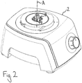
- FIG. 2 a view of the lower mixer base 2 of the mixer 1 according to the invention is shown.
- Two concentric coupling devices 7 and 9 protrude from the mixer base 2 and rotate about a common axis A at different speeds.
- the upper, first coupling device 7 with a toothing which is provided for driving a rotating first tool 6 at a lower speed, rotates more slowly than the lower, second coupling device 9, also with a toothing, which is used for the drive a rotating second tool 10 is provided at a higher speed.
- the toothings can be simple gearwheels, toothed shafts or stub shafts into which a crown gear toothing formed on the circumference of a cylinder is introduced.
Landscapes
- Engineering & Computer Science (AREA)
- Mechanical Engineering (AREA)
- Food Science & Technology (AREA)
- Food-Manufacturing Devices (AREA)
Description
- Die Erfindung betrifft einen Mixer, insbesondere zum Mixen von Nahrungsmitteln in haushaltsüblichen Mengen, aufweisend einen Mixersockel, in welchem mindestens ein Antriebsmotor angeordnet ist, und einen krugförmigen Aufsatz, der ein rotierendes Werkzeug aufweist, wobei der Mixersockel und der krugförmige Aufsatz voneinander trennbar ausgestaltet sind, und wobei mindestens eine Antriebswelle des Antriebsmotors aus dem Mixersockel herausgeführt ist und eine erste Kupplungsvorrichtung für eine korrespondierende erste Gegenkupplungsvorrichtung am Boden des krugförmigen Aufsatzes aufweist. Die Erfindung betrifft außerdem einen Mixersockel für einen von dem Mixersockel anbringbaren und davon wieder lösbaren krugförmigen Aufsatz. Schließlich betrifft die Erfindung einen krugförmigen Aufsatz zum wieder-lösbaren Anbringen an einen Mixersockel.
- Zum Herstellen von Nahrungsmittelgerichten mit Hilfe einer gattungsgemäßen Küchenmaschine, die zum Häckseln von Gemüse und zum Mischen oder zum Zerkleinern von Eis geeignet ist, ist es bekannt, während des Mixvorgangs weitere Zutaten zum Mixerinhalt dazuzugeben. Die Kräfte und die Unwuchten, die auf das rotierende Messer einer Küchenmaschine wirken, erfordern eine recht stabile Lagerung. In der Regel sind bekannte Küchenmixer daher mit einem am Boden des krugförmigen Mixers angeordneten rotierenden Messer ausgestattet, welches einseitig an einem kurzen Wellenstumpf angeordnet ist. Ein so aufgebauter Mixer kann in Mixportionsgrößen in haushaltsüblichen Mengen 1 kW und mehr mechanische Leistung in das zu mixende Nahrungsmittel einbringen.
- Mit einem am Boden angeordneten rotierenden Messer ist es unpraktisch, beispielsweise Gemüse mit einem rotierenden Scheibenmesser zu schneiden, da unterhalb des Scheibenmessers kein Platz zur Aufnahme der Gemüsescheiben vorhanden ist. Hierzu ist es auch bekannt, den Wellenstumpf zu verlängern, so dass eine Schneidscheibe mit viel Raum unterhalb der Schneidscheibe ausgestattet ist. Die verlängerte Welle ist aber empfindlich gegenüber Unwuchten. Auf-grund der Hebelwirkung kann eine solche Schneidscheibe weniger mechanische Leistung abgeben, wenn keine Vorkehrungen zur mechanisch hochstabilen Lagerung der Schneidscheibe vorgesehen sind.
- Ein besonderer Fall ist gegeben, wenn ein Gericht länger gerührt oder gemixt werden soll und gleichzeitig in das gerührte oder gemixte Gericht weitere Zutaten unter Zerkleinerung eingebracht werden sollen. Als Beispiel sei genannt, das Herstellen von Eis aus Wassereis und einer Eismischung, oder aus gefrorenen Früchten und Eischnee, in das geraspelte Schokolade eingebracht werden soll oder aber ein Risotto, das längere Zeit in der Wärme gerührt werden muss, und in das gleichzeitig zerkleinertes Gemüse oder Pilze eingebracht werden sollen.
- Ein auf einer gemeinsamen Welle angeordneter Rührer oder Mixer und eine Schneidscheibe müssten stets bei gleicher Umdrehungsgeschwindigkeit gedreht werden. Mixen und Schneiden erfordern in der Regel eine unterschiedliche Umdrehungsgeschwindigkeit, so dass ein gleichzeitiger Einsatz von Mixen und Schneiden auf einer gemeinsamen Welle in vielen Fällen nicht möglich ist oder zu unerwünschten Ergebnissen führt.
- Aufgabe der Erfindung ist es daher, einen verbesserten Mixer zur Verfügung zu stellen. Insbesondere soll ein Mixer zur Verfügung gestellt werden, mit dem gleichzeitig gerührt oder gemixt werden kann und Nahrungsmittel zerkleinert werden können. Der Erfindung liegt außerdem die Aufgabe zugrunde, einen verbesserten Mixersockel und einen verbesserten krugförmigen Aufsatz für einen Mixer bereitzustellen.
- Die Bezugszeichen in sämtlichen Ansprüchen haben keine einschränkende Wirkung, sondern sollen lediglich deren Lesbarkeit verbessern.
- Die der Erfindung zu Grunde liegende Aufgabe wird durch einen eingangs erwähnten Mixer gelöst, bei dem vorgesehen ist, dass eine zweite Kupplungsvorrichtung für eine korrespondierende zweite Gegenkupplungsvorrichtung des krugförmigen Ansatzes am Mixersockel angeordnet ist. Im Sinne der vorliegenden Erfindung bedeutet krugförmig, dass der Aufsatz als ein oben offenes Gefäß augebildet ist.
- Die Erfindungsaufgabe wird außerdem durch einen Mixersockel für einen an dem Mixersockel anbringbaren und davon wieder lösbaren krugförmigen Aufsatz, der in seinem Inneren ein rotierendes erstes Werkzeug aufweist, insbesondere zum Mixen von Nahrungsmitteln in haushaltsüblichen Mengen, wobei in dem Mixersockel mindestens ein Antriebsmotor angeordnet ist, mindestens eine Antriebswelle des Antriebsmotors aus dem Mixersockel herausgeführt ist und der Mixersockel eine erste Kupplungsvorrichtung für eine korrespondierende erste Gegenkupplungsvorrichtung am Boden des krugförmigen Aufsatzes aufweist. Der Mixersockel weist außerdem eine zweite Kupplungsvorrichtung für eine korrespondierende zweite Gegenkupplungsvorrichtung des Ansatzes auf.
- Schließlich wird die Erfindungsaufgabe auch durch einen krugförmigen Aufsatz zum wieder-lösbaren Anbringen an einen Mixersockel, insbesondere zum Mixen von Nahrungsmitteln in haushaltsüblichen Mengen, gelöst, wobei der Aufsatz im Inneren ein rotierendes erstes Werkzeug aufweist sowie eine erste Gegenkupplungsvorrichtung (8) für eine korrespondierende erste Kupplungsvorrichtung (7) des Mixersockels (2). Außerdem weist der Aufsatz eine zweite Gegenkupplungsvorrichtung für eine korrespondierende zweite Kupplungsvorrichtung des Mixersockels auf.
- Nach dem Gedanken der Erfindung ist also vorgesehen, dass ein Mixer mehr als einen Antrieb, bevorzugt einen doppelten Antrieb aufweist. Durch den mehr als einen oder doppelten Antrieb kann auch mehr als ein rotierendes Werkzeug, z. B. ein Mixmesserwerkzeug oder ein Mixschaufelwerkzeug als erstes Werkzeug und ein Scheibenmesser als zweites Werkzeug, gleichzeitig angetrieben werden.
- Der bevorzugte Mixer ist ein Standmixer. Der Mixer kann aber zum Beispiel auch eine Küchenmaschine sein, an die der Aufsatz in Form eines Mixgefäßes wieder-lösbar ankuppelbar ist. Der typische Aufsatz besteht, zumindest im Wesentlichen aus Glas oder Kunststoff. Er weist vorzugsweise einen Henkel auf, mit dem ein Benutzer den Aufsatz angreifen kann.
- Mit dem erfindungsgemäßen Mixer, dem erfindungsgemäßen Mixersockel und dem erfindungsgemäßen krugförmigen Aufsatz lässt sich das Spektrum möglicher Anwendungen des Mixers vorteilhafterweise erweitern. Insbesondere kann gleichzeitig gerührt oder gemixt und Nahrungsmittel zerkleinert werden.
- Vorteilhafte Aus- und Weiterbildungen, welche einzeln oder in Kombination miteinander eingesetzt werden können, sind Gegenstand der abhängigen Ansprüche und der nachfolgenden Beschreibung.
- Der Mixer kann eine doppelte Antriebsfunktion auf einer Welle aufweisen, wobei beide Antriebsfunktionen unterschiedliche Geschwindigkeiten aufweisen. Diese doppelte Antriebsfunktion kann über einen koaxialen Antrieb mit zwei Kupplungen erfolgen, die ineinander oder übereinander angeordnet sind. Dabei kann es vorgesehen sein, dass sich die erste Kupplungsvorrichtung und auch die zweite Kupplungsvorrichtung koaxial um eine gemeinsame Achse drehen. Dies kann durch zwei unabhängig voneinander angetriebene Wellen erfolgen, aber auch durch zwei auf einer Achse sitzende Wellen, die beispielsweise miteinander durch ein Planetengetriebe oder ein anderes Getriebe miteinander verbunden sind.
- Bei dem Getriebe kann es sich um ein Wechselgetriebe handeln, wobei in bevorzugter Weise mehr als ein Planetengetriebe auf einer Welle angeordnet sind, wobei das Sonnenrad als Antriebsrad und die Zentren der Planetenräder als Abtrieb für eine zweite Wellen dienen. Dabei können verschiedene Radienverhältnisse von Sonnenrad und Planetenrädern untereinander vorliegen, wobei ein Antrieb mit durch koaxiales Verschieben der Antriebswelle mit verschiedenen Sonnenrädern in Eingriff kommt. Es ist aber auch möglich, dass ein herkömmliches Zahnradgetriebe mit parallel verlaufenden Getriebewellen verschiedene koaxiale Wellen antreibt. Dabei ist es je nach Ausgestaltung des erfindungsgemäßen Mixers möglich, dass die erste Kupplungsvorrichtung und auch die zweite Kupplungsvorrichtung über ein Getriebe miteinander verbunden sind.
- Vorteilhaft ist es, wenn die der ersten Kupplungsvorrichtung zugeordnete Antriebswelle und eine der zweiten Kupplungsvorrichtung zugeordnete Antriebswelle mit unterschiedlicher Umdrehungsgeschwindigkeit rotieren. Auf diese Weise lässt sich gleichzeitig beispielsweise ein schnelles Schneiden mit einem Scheibenmesser und ein langsames Rühren oder Mixen mit einem rotierenden Mixmesser erreichen. Dazu ist es von besonderem Vorteil, wenn die Antriebsgeschwindigkeiten der beiden Antriebswellen gemeinsam oder getrennt voneinander einstellbar sind.
- Je nach Ausgestaltung des Mixers kann es vorgesehen sein, dass die erste Kupplungsvorrichtung und auch die zweite Kupplungsvorrichtung durch denselben Antriebsmotor angetrieben werden.
- Um eine einfache Kupplung zwischen dem Mixersockel und dem krugförmigen Aufsatz des Mixers herzustellen, ist es in Ausgestaltung des Mixers vorgesehen, dass die erste Kupplungsvorrichtung und auch die zweite Kupplungsvorrichtung je eine auf einem Umfang eines Zylinders eingeformte Kronradverzahnung aufweisen. Diese auf einem Umfang eines Zylinders eingeformte Kronradverzahnung erinnert an ein gattungsgemäßes Zahnrad, bei dem ein Teil des Umfangs der Zähne miteinander verbunden ist. Das Zahnrad weist also neben Senken und Höhen auch einen durchgehenden zylindrischen Teil auf, wobei der durchgehende zylindrische Teil des Zahnrades unten liegt und die Senken und Höhen eines liegenden Zahnrades nach oben weisen.
- Es ist vorteilhaft, wenn zwei Vorrichtungen, wie Scheibenmesser, rotierendes Sternmesser oder Mischvorrichtung in Form eines Propellers in unterschiedlicher Höhe innerhalb des krugförmigen Aufsatzes angeordnet sind. Das bevorzugte erste Werkzeug weist ein oder mehrere Messer auf, um Mixgut in dem Aufsatz des Mixers zu zerkleinern. Das bevorzugte erste Werkzeug ist im Inneren des Aufsatzes in der Nähe des Bodens des Aufsatzes angeordnet. Das zweite Werkzeug weist vorzugsweise ebenfalls ein oder mehrere Messer auf, zum Beispiel zum Schneiden von Scheiben. Das bevorzugte zweite Werkzeug ist in der Nähe der oberen Öffnung des Gefäßes, also in Randnähe angeordnet. Dabei ist in Ausgestaltung der Erfindung vorgesehen, dass eine erste Gegenkupplungsvorrichtung innerhalb des krugförmigen Aufsatzes mit einem rotierenden ersten Werkzeug, beispielsweise ein Sternmesser, oder Mischer, beispielsweise in Propellerform, in Bodennähe des krugförmigen Aufsatzes verbunden ist und dass eine zweite Gegenkupplungsvorrichtung mit einem rotierenden zweiten Werkzeug, beispielsweise ein Scheibenmesser, in Randnähe des krugförmigen Aufsatzes verbunden ist.
- Je nach Einsatzart rotiert das untere erste Werkzeug, z. B. ein Sternmesser oder ein propellerförmiger Mischer, langsamer und das obere zweite Werkzeug, z. B. ein Scheibenmesser, schneller. Dabei kann vorgesehen sein, dass sich das rotierende erste Werkzeug mit niedrigerer Umdrehungsgeschwindigkeit dreht als das zweite Werkzeug.
- Um die Empfindlichkeit gegenüber Unwuchten oder gegenüber einseitiger Belastung zu verringern, kann in Ausgestaltung der Erfindung vorgesehen sein, dass eine innerhalb des krugförmigen Aufsatzes vom Boden bis zur Randnähe erstreckende Welle durch ein Lager gelagert ist, welches selbst in einem Stabilierungsgestänge innerhalb des krugförmigen Aufsatzes aufgenommen ist.
- Weitere vorteilhafte Ausgestaltungen werden nachfolgend anhand mehrerer in den Zeichnungen dargestellten Ausführungsbeispielen, auf welche die Erfindung jedoch nicht beschränkt ist, näher beschrieben.
- Es zeigt schematisch:
- Figur 1
- einen erfindungsgemäßen Mixer bestehend aus einem Mixersockel mit Antriebsmotor und einem krugförmigen Aufsatz, Mixersockel und krugförmiger Aufsatz ist aufgeschnitten dargestellt,
- Figur 2
- ein Mixersockel mit zwei konzentrischen Kupplungsvorrichtungen, und
- Figur 3
- ein krugförmiger Aufsatz des erfindungsgemäßen Mixers mit Blick auf die zwei innenliegenden Gegenkupplungsvorrichtungen.
- Bei der nachfolgenden Beschreibung von bevorzugten Ausführungsformen der vorliegenden Erfindung bezeichnen gleiche Bezugszeichen gleiche oder vergleichbare Komponenten.
- In
Figur 1 ist ein erfindungsgemäßer Mixer 1 bestehend aus einem Mixersockel 2 mit Antriebsmotor 3 und einem krugförmigen Aufsatz 4 in teilweise aufgeschnittener Ansicht dargestellt. Dabei ist der Antriebsmotor 3 innerhalb des Mixersockels 2 angeordnet und ragt mit einer Antriebswelle aus dem Mixersockel 2 heraus, was in dieser Darstellung durch den krugförmigen Aufsatz 4 verdeckt ist. Nach dem Gedanken der Erfindung ist es vorgesehen, dass mindestens eine Antriebswelle des Antriebsmotors 3 aus dem Mixersockel 2 herausgeführt ist und eine erste Kupplungsvorrichtung 7 (Figur 2 ) aufweist, die zum Eingriff in eine korrespondierende erste Gegenkupplungsvorrichtung 8 (Figur 3 ) am Boden 5 des krugförmigen Aufsatzes 4 vor-gesehen ist. Des Weiteren ist vorgesehen, dass eine zweite Kupplungsvorrichtung 9 (Figur 2 ) für eine korrespondierende, zweite Gegenkupplungsvorrichtung 10 des krugförmigen Ansatzes 4 am Mixersockel 2 angeordnet ist. - Durch die Kupplungsvorrichtungen 7 kann ein im krugförmigen Aufsatz 4 dem Boden 5 nahes erstes Werkzeug 6, beispielsweise ein Sternmesser, mit einer ersten, z. B. niedrigeren Geschwindigkeit betrieben werden, und gleichzeitig kann durch die Kupplungsvorrichtung 9 ein im krugförmigen Aufsatz 4 dem Rand 4" nahes zweites Werkzeug (11), beispielsweise ein Scheibenmesser, mit einer zweiten, z. B. höheren Umdrehungsgeschwindigkeit betrieben werden. Auf die exakte Umdrehungsgeschwindigkeit der Werkzeuge kommt es hier nicht an, wichtig ist jedoch, dass der Geschwindigkeitsunterschied so gewählt werden kann, dass für die Nutzung des unteren rotierenden ersten Werkzeugs 6 und für die Nutzung des oberen zweiten Werkzeugs 11 die jeweils angemessene Geschwindigkeit gewählt werden kann. Innerhalb des krugförmigen Aufsatzes ist eine Welle 12 vorhanden, welche das obere zweite Werkzeug 11 antreibt. Diese Welle ist in einem Lager 13 gelagert. Das Lager 13 seinerseits in einem Stabilisierungsgestänge 14, hier in Form von drei Armen, die mit dem Deckel verbunden sind, aufgenommen. Durch diese zusätzliche Lagerung ist die Welle 12 dazu in der Lage die Unwucht und die einseitige Kraftbeanspruchung beim Häckseln oder Scheibenschneiden aufzunehmen ohne, dass die Unwucht das Werkzeug aus seiner Verankerung reißt.
- In
Figur 2 ist ein Blick auf den unteren Mixersockel 2 des erfindungsgemäßen Mixers 1 dargestellt. Aus dem Mixersockel 2 ragen zwei konzentrische Kupplungsvorrichtungen 7 und 9 heraus, die mit unterschiedlicher Umdrehungsgeschwindigkeit um eine gemeinsame Achse A drehen. In dem hier dargestellten Mixersockel 2 rotiert die obere, erste Kupplungsvorrichtung 7 mit einer Verzahnung, die für den Antrieb eines rotierenden ersten Werkzeugs 6 mit niedrigerer Geschwindigkeit vorgesehen ist, langsamer als die untere, zweite Kupplungsvorrichtung 9, ebenfalls mit einer verzahnung, die für den Antrieb eines rotierenden zweiten Werkzeugs 10 mit höherer Geschwindigkeit vorgesehen ist. Bei den Verzahnungen kann es sich um einfache Zahnräder handeln, Zahnwellen oder um Wellenstümpfe, in die eine auf einem Umfang eines Zylinders eingeformte Kronradverzahnung eingebracht ist. - In
Figur 3 ist schließlich ein aufgeschnittener krugförmiger Aufsatz 4 mit Henkel 4' zum Greifen mit der menschlichen Hand dargestellt, in welchem sowohl ein unteres erstes Werkzeug 6 und die Welle 12 ausFigur 1 entfernt ist. Dadurch wird der Blick auf innere Kupplungsvorrichtungen 8' und 10' frei, die zur Kupplung mit dem unteren ersten Werkzeug 6 und der Welle 12 vorgesehen sind. Die rotierenden Kupplungen sind über eine hier nicht gezeigte Welle miteinander verbunden, die über einen Simmering abgedichtet ist. - Die in der vorstehenden Beschreibung, den Ansprüchen und den Zeichnungen offenbarten Merkmale können sowohl einzeln als auch in beliebiger Kombination für die Verwirklichung der Erfindung in ihren verschiedenen Ausführungsformen von Bedeutung sein.
-
- 1
- Mixer
- 2
- Mixersockel
- 3
- Antriebsmotor
- 4
- krugförmiger Aufsatz
- 4'
- Henkel
- 4"
- Rand
- 5
- Boden
- 6
- Erstes Werkzeug
- 7
- Erste Kupplungsvorrichtung
- 8
- Erste Gegenkupplungsvorrichtung
- 8'
- Erste Innere Kupplungsvorrichtung
- 9
- Zweite Kupplungsvorrichtung
- 10
- Zweite Gegenkupplungsvorrichtung
- 10'
- Zweite Innere Kupplungsvorrichtung
- 11
- Zweites Werkzeug
- 12
- Welle
- 13
- Lager
- 14
- Stabilisierungsgestänge
- A
- Achse
Claims (10)
- Mixer (1), insbesondere zum Mixen von Nahrungsmitteln in haushaltsüblichen Mengen, aufweisend- einen Mixersockel (2), in welchem mindestens ein Antriebsmotor (3) angeordnet ist, und- einen krugförmigen Aufsatz (4), der ein rotierendes erstes Werkzeug (6) aufweist, wobei der Mixersockel (2) und der krugförmige Aufsatz (4) voneinander trennbar ausgestaltet sind, undwobei mindestens eine Antriebswelle des Antriebsmotors (3) aus dem Mixersockel (2) herausgeführt ist und eine erste Kupplungsvorrichtung (7) für eine korrespondierende erste Gegenkupplungsvorrichtung (8) am Boden (5) des krugförmigen Aufsatzes (4) aufweist, wobei eine zweite Kupplungsvorrichtung (9) für eine korrespondierende zweite Gegenkupplungsvorrichtung (10) des krugförmigen Ansatzes (4) am Mixersockel (2) angeordnet ist, dadurch gekennzeichnet, dass die der ersten Kupplungsvorrichtung (7) zugeordnete Antriebswelle und eine der zweiten Kupplungsvorrichtung (9) zugeordnete Antriebswelle gleichzeitig mit unterschiedlicher Umdrehungsgeschwindigkeit rotieren
- Mixer nach Anspruch 1, dadurch gekennzeichnet, dass sich die erste Kupplungsvorrichtung (7) und auch die zweite Kupplungsvorrichtung (9) koaxial um eine gemeinsame Achse (A) drehen.
- Mixer nach einem der Ansprüche 1 oder 2, dadurch gekennzeichnet, dass die erste Kupplungsvorrichtung (7) und auch die zweite Kupplungsvorrichtung (9) über ein Getriebe miteinander verbunden sind.
- Mixer nach einem der Ansprüche 1 bis 3, dadurch gekennzeichnet, dass die Antriebsgeschwindigkeiten der beiden Antriebswellen gemeinsam oder getrennt voneinander einstellbar sind.
- Mixer nach Anspruch 3, dadurch gekennzeichnet, dass die erste Kupplungsvorrichtung (7) und auch die zweite Kupplungsvorrichtung (9) durch denselben Antriebsmotor (3) angetrieben werden.
- Mixer nach einem der Ansprüche 1 bis 5, dadurch gekennzeichnet, dass die erste Kupplungsvorrichtung (7) und auch die zweite Kupplungsvorrichtung (9) je eine auf einem Umfang eines Zylinders eingeformte Kronradverzahnung aufweisen.
- Mixer nach einem der Ansprüche 1 bis 6, dadurch gekennzeichnet, dass eine erste Gegenkupplungsvorrichtung (8) innerhalb des krugförmigen Aufsatzes (4) mit einem rotierenden ersten Werkzeug (6) oder Mischer in Bodennähe des krugförmigen Aufsatzes (4) verbunden ist und dass eine zweite Gegenkupplungsvorrichtung (10) mit einem rotierenden zweiten Werkzeug (11) in Randnähe des krugförmigen Aufsatzes (4) verbunden ist.
- Mixer nach Anspruch 7, dadurch gekennzeichnet, dass sich das rotierende erste Werkzeug (6) oder sich der rotierende Mischer in Bodennähe des krugförmigen Aufsatzes (4) mit niedrigerer Umdrehungsgeschwindigkeit dreht als das in Randnähe rotierende zweiten Werkzeug (11).
- Mixer nach Anspruch 8, dadurch gekennzeichnet, dass eine innerhalb des krugförmigen Aufsatzes (4) vom Boden (5) bis zur Randnähe erstreckende Welle (12) durch ein Lager (13) gelagert ist, welches selbst in einem Stabilierungsgestänge (14) innerhalb des krugförmigen Aufsatzes (4) aufgenommen ist.
- Mixersockel (2) mit einem an dem Mixersockel (2) anbringbaren und davon wieder lösbaren krugförmigen Aufsatz (4), der in seinem Inneren ein rotierendes erstes Werkzeug (6) aufweist, insbesondere zum Mixen von Nahrungsmitteln in haushaltsüblichen Mengen, wobei in dem Mixersockel (2) mindestens ein Antriebsmotor (3) angeordnet ist, mindestens eine Antriebswelle des Antriebsmotors (3) aus dem Mixersockel (2) herausgeführt ist und der Mixersockel eine erste Kupplungsvorrichtung (7) für eine korrespondierende erste Gegenkupplungsvorrichtung (8) am Boden (5) des krugförmigen Aufsatzes (4) aufweist, wobei der Mixersockel (2) eine zweite Kupplungsvorrichtung (9) für eine korrespondierende zweite Gegenkupplungsvorrichtung (10) des Ansatzes (4) aufweist, dadurch gekennzeichnet, dass die der ersten Kupplungsvorrichtung (7) zugeordnete Antriebswelle und eine der zweiten Kupplungsvorrichtung (9) zugeordnete Antriebswelle gleichzeitig mit unterschiedlicher Umdrehungsgeschwindigkeit rotieren
Priority Applications (2)
| Application Number | Priority Date | Filing Date | Title |
|---|---|---|---|
| SI201830205T SI3488743T1 (sl) | 2017-11-27 | 2018-11-21 | Mešalnik z dvojno pogonsko funkcijo na osi |
| PL18207517T PL3488743T3 (pl) | 2017-11-27 | 2018-11-21 | Mikser z podwójną funkcją napędową na jednym wale |
Applications Claiming Priority (1)
| Application Number | Priority Date | Filing Date | Title |
|---|---|---|---|
| DE102017221140.7A DE102017221140A1 (de) | 2017-11-27 | 2017-11-27 | Mixer mit doppelter Antriebsfunktion auf einer Welle |
Publications (2)
| Publication Number | Publication Date |
|---|---|
| EP3488743A1 EP3488743A1 (de) | 2019-05-29 |
| EP3488743B1 true EP3488743B1 (de) | 2021-01-06 |
Family
ID=64426745
Family Applications (1)
| Application Number | Title | Priority Date | Filing Date |
|---|---|---|---|
| EP18207517.6A Active EP3488743B1 (de) | 2017-11-27 | 2018-11-21 | Mixer mit doppelter antriebsfunktion auf einer welle |
Country Status (4)
| Country | Link |
|---|---|
| EP (1) | EP3488743B1 (de) |
| DE (1) | DE102017221140A1 (de) |
| PL (1) | PL3488743T3 (de) |
| SI (1) | SI3488743T1 (de) |
Families Citing this family (2)
| Publication number | Priority date | Publication date | Assignee | Title |
|---|---|---|---|---|
| CN211155372U (zh) * | 2019-09-26 | 2020-08-04 | 浙江绍兴苏泊尔生活电器有限公司 | 主机和料理机 |
| US12514403B2 (en) | 2022-03-30 | 2026-01-06 | Whirlpool Corporation | Countertop appliance |
Family Cites Families (4)
| Publication number | Priority date | Publication date | Assignee | Title |
|---|---|---|---|---|
| DE1079597B (de) * | 1952-03-12 | 1960-04-14 | Peter Willems | Misch- und Dispergiervorrichtung |
| DE3408692A1 (de) * | 1984-03-09 | 1985-09-19 | Robert Krups Stiftung & Co KG, 5650 Solingen | Elektrisch betriebenes geraet fuer die bearbeitung und zubereitung von nahrungsmitteln aller art |
| EP2790557B1 (de) * | 2011-12-12 | 2017-08-02 | SharkNinja Operating LLC | Multifunktions-lebensmittelverarbeitungssystem |
| FR3009942B1 (fr) * | 2013-08-29 | 2015-09-25 | Seb Sa | Appareil electromenager de preparation culinaire comportant un outil de travail venant s'engager de maniere amovible sur un entraineur |
-
2017
- 2017-11-27 DE DE102017221140.7A patent/DE102017221140A1/de not_active Ceased
-
2018
- 2018-11-21 PL PL18207517T patent/PL3488743T3/pl unknown
- 2018-11-21 SI SI201830205T patent/SI3488743T1/sl unknown
- 2018-11-21 EP EP18207517.6A patent/EP3488743B1/de active Active
Non-Patent Citations (1)
| Title |
|---|
| None * |
Also Published As
| Publication number | Publication date |
|---|---|
| EP3488743A1 (de) | 2019-05-29 |
| SI3488743T1 (sl) | 2021-03-31 |
| DE102017221140A1 (de) | 2019-05-29 |
| PL3488743T3 (pl) | 2021-06-28 |
Similar Documents
| Publication | Publication Date | Title |
|---|---|---|
| EP1449472B2 (de) | Handantreibbares Gerät zum Zerkleinern von Lebensmitteln | |
| EP2015660B1 (de) | Gerät zum bearbeiten von lebensmitteln | |
| DE1219640B (de) | Scherenartig wirkende Zerkleinerungsvorrichtung fuer Nahrungsmittel od. dgl. | |
| DE202009011685U1 (de) | Vorrichtung zur Verarbeitung von Lebensmitteln | |
| EP0158032B1 (de) | Elektrisch betriebenes Gerät für die Bearbeitung und Zubereitung von Nahrungsmitteln aller Art | |
| DE10235326A1 (de) | Vorrichtung zur Verarbeitung der Ausgangsstoffe eines Nahrungsmittelproduktes | |
| DE4414415C1 (de) | Zusatzgerät für einen elektrisch betriebenen Handrührer | |
| EP3503782B1 (de) | Getriebeeinheit für eine küchenmaschine | |
| EP2887849B1 (de) | Rotor mit freilauf | |
| EP3473107B1 (de) | Vorrichtung und verfahren zum be- und verarbeiten von schokolade sowie verwendung einer universalmaschine dafür | |
| DE3921115A1 (de) | Universalkuechenmaschine | |
| EP3488743A1 (de) | Mixer mit doppelter antriebsfunktion auf einer welle | |
| CN208551048U (zh) | 一种正反双向转动刀片传动装置及其搅拌机 | |
| EP0570677B1 (de) | Zerkleinerungs- und Mischeinrichtung für eine Vielzweckküchenmaschine | |
| EP2785228B1 (de) | Aufsatz einer küchenmaschine | |
| DE102014220631B4 (de) | Küchengerät zum Zerkleinern eines Bearbeitungsguts | |
| DE102011052093B3 (de) | Schälschleuder zum Schälen von Lebensmitteln | |
| DE1052079B (de) | Misch- oder Zerkleinerungsgeraet fuer den Haushalt | |
| EP3492164B1 (de) | Topfmixer mit mixer-messer | |
| DE3144438A1 (de) | Kuechenmaschine mit motorischem antrieb | |
| DE4322280A1 (de) | Arbeitsbehälter für eine elektrisch betriebene Haushaltsküchenmaschine | |
| EP4578350A1 (de) | Multifunktionsküchenmaschine | |
| DE977303C (de) | Auf einen elektromotorischen Antriebssockel fuer hochtourige Kuechengeraete aufsetzbarer Arbeitsbehaelter | |
| DE102017221182B4 (de) | Mixer mit variablem Volumen | |
| DE112024001663T5 (de) | Effiziente Mischbehälter |
Legal Events
| Date | Code | Title | Description |
|---|---|---|---|
| PUAI | Public reference made under article 153(3) epc to a published international application that has entered the european phase |
Free format text: ORIGINAL CODE: 0009012 |
|
| STAA | Information on the status of an ep patent application or granted ep patent |
Free format text: STATUS: THE APPLICATION HAS BEEN PUBLISHED |
|
| AK | Designated contracting states |
Kind code of ref document: A1 Designated state(s): AL AT BE BG CH CY CZ DE DK EE ES FI FR GB GR HR HU IE IS IT LI LT LU LV MC MK MT NL NO PL PT RO RS SE SI SK SM TR |
|
| AX | Request for extension of the european patent |
Extension state: BA ME |
|
| STAA | Information on the status of an ep patent application or granted ep patent |
Free format text: STATUS: REQUEST FOR EXAMINATION WAS MADE |
|
| 17P | Request for examination filed |
Effective date: 20191129 |
|
| RBV | Designated contracting states (corrected) |
Designated state(s): AL AT BE BG CH CY CZ DE DK EE ES FI FR GB GR HR HU IE IS IT LI LT LU LV MC MK MT NL NO PL PT RO RS SE SI SK SM TR |
|
| GRAP | Despatch of communication of intention to grant a patent |
Free format text: ORIGINAL CODE: EPIDOSNIGR1 |
|
| STAA | Information on the status of an ep patent application or granted ep patent |
Free format text: STATUS: GRANT OF PATENT IS INTENDED |
|
| INTG | Intention to grant announced |
Effective date: 20200824 |
|
| GRAS | Grant fee paid |
Free format text: ORIGINAL CODE: EPIDOSNIGR3 |
|
| GRAA | (expected) grant |
Free format text: ORIGINAL CODE: 0009210 |
|
| STAA | Information on the status of an ep patent application or granted ep patent |
Free format text: STATUS: THE PATENT HAS BEEN GRANTED |
|
| AK | Designated contracting states |
Kind code of ref document: B1 Designated state(s): AL AT BE BG CH CY CZ DE DK EE ES FI FR GB GR HR HU IE IS IT LI LT LU LV MC MK MT NL NO PL PT RO RS SE SI SK SM TR |
|
| REG | Reference to a national code |
Ref country code: GB Ref legal event code: FG4D Free format text: NOT ENGLISH |
|
| REG | Reference to a national code |
Ref country code: AT Ref legal event code: REF Ref document number: 1351394 Country of ref document: AT Kind code of ref document: T Effective date: 20210115 Ref country code: CH Ref legal event code: EP |
|
| REG | Reference to a national code |
Ref country code: DE Ref legal event code: R096 Ref document number: 502018003548 Country of ref document: DE |
|
| REG | Reference to a national code |
Ref country code: IE Ref legal event code: FG4D Free format text: LANGUAGE OF EP DOCUMENT: GERMAN |
|
| REG | Reference to a national code |
Ref country code: NL Ref legal event code: MP Effective date: 20210106 |
|
| REG | Reference to a national code |
Ref country code: LT Ref legal event code: MG9D |
|
| PG25 | Lapsed in a contracting state [announced via postgrant information from national office to epo] |
Ref country code: BG Free format text: LAPSE BECAUSE OF FAILURE TO SUBMIT A TRANSLATION OF THE DESCRIPTION OR TO PAY THE FEE WITHIN THE PRESCRIBED TIME-LIMIT Effective date: 20210406 Ref country code: HR Free format text: LAPSE BECAUSE OF FAILURE TO SUBMIT A TRANSLATION OF THE DESCRIPTION OR TO PAY THE FEE WITHIN THE PRESCRIBED TIME-LIMIT Effective date: 20210106 Ref country code: FI Free format text: LAPSE BECAUSE OF FAILURE TO SUBMIT A TRANSLATION OF THE DESCRIPTION OR TO PAY THE FEE WITHIN THE PRESCRIBED TIME-LIMIT Effective date: 20210106 Ref country code: GR Free format text: LAPSE BECAUSE OF FAILURE TO SUBMIT A TRANSLATION OF THE DESCRIPTION OR TO PAY THE FEE WITHIN THE PRESCRIBED TIME-LIMIT Effective date: 20210407 Ref country code: NO Free format text: LAPSE BECAUSE OF FAILURE TO SUBMIT A TRANSLATION OF THE DESCRIPTION OR TO PAY THE FEE WITHIN THE PRESCRIBED TIME-LIMIT Effective date: 20210406 Ref country code: PT Free format text: LAPSE BECAUSE OF FAILURE TO SUBMIT A TRANSLATION OF THE DESCRIPTION OR TO PAY THE FEE WITHIN THE PRESCRIBED TIME-LIMIT Effective date: 20210506 Ref country code: LT Free format text: LAPSE BECAUSE OF FAILURE TO SUBMIT A TRANSLATION OF THE DESCRIPTION OR TO PAY THE FEE WITHIN THE PRESCRIBED TIME-LIMIT Effective date: 20210106 |
|
| PG25 | Lapsed in a contracting state [announced via postgrant information from national office to epo] |
Ref country code: LV Free format text: LAPSE BECAUSE OF FAILURE TO SUBMIT A TRANSLATION OF THE DESCRIPTION OR TO PAY THE FEE WITHIN THE PRESCRIBED TIME-LIMIT Effective date: 20210106 Ref country code: RS Free format text: LAPSE BECAUSE OF FAILURE TO SUBMIT A TRANSLATION OF THE DESCRIPTION OR TO PAY THE FEE WITHIN THE PRESCRIBED TIME-LIMIT Effective date: 20210106 Ref country code: SE Free format text: LAPSE BECAUSE OF FAILURE TO SUBMIT A TRANSLATION OF THE DESCRIPTION OR TO PAY THE FEE WITHIN THE PRESCRIBED TIME-LIMIT Effective date: 20210106 |
|
| PG25 | Lapsed in a contracting state [announced via postgrant information from national office to epo] |
Ref country code: IS Free format text: LAPSE BECAUSE OF FAILURE TO SUBMIT A TRANSLATION OF THE DESCRIPTION OR TO PAY THE FEE WITHIN THE PRESCRIBED TIME-LIMIT Effective date: 20210506 |
|
| REG | Reference to a national code |
Ref country code: DE Ref legal event code: R097 Ref document number: 502018003548 Country of ref document: DE |
|
| PG25 | Lapsed in a contracting state [announced via postgrant information from national office to epo] |
Ref country code: SM Free format text: LAPSE BECAUSE OF FAILURE TO SUBMIT A TRANSLATION OF THE DESCRIPTION OR TO PAY THE FEE WITHIN THE PRESCRIBED TIME-LIMIT Effective date: 20210106 Ref country code: CZ Free format text: LAPSE BECAUSE OF FAILURE TO SUBMIT A TRANSLATION OF THE DESCRIPTION OR TO PAY THE FEE WITHIN THE PRESCRIBED TIME-LIMIT Effective date: 20210106 Ref country code: EE Free format text: LAPSE BECAUSE OF FAILURE TO SUBMIT A TRANSLATION OF THE DESCRIPTION OR TO PAY THE FEE WITHIN THE PRESCRIBED TIME-LIMIT Effective date: 20210106 |
|
| PLBE | No opposition filed within time limit |
Free format text: ORIGINAL CODE: 0009261 |
|
| STAA | Information on the status of an ep patent application or granted ep patent |
Free format text: STATUS: NO OPPOSITION FILED WITHIN TIME LIMIT |
|
| PG25 | Lapsed in a contracting state [announced via postgrant information from national office to epo] |
Ref country code: DK Free format text: LAPSE BECAUSE OF FAILURE TO SUBMIT A TRANSLATION OF THE DESCRIPTION OR TO PAY THE FEE WITHIN THE PRESCRIBED TIME-LIMIT Effective date: 20210106 Ref country code: RO Free format text: LAPSE BECAUSE OF FAILURE TO SUBMIT A TRANSLATION OF THE DESCRIPTION OR TO PAY THE FEE WITHIN THE PRESCRIBED TIME-LIMIT Effective date: 20210106 Ref country code: SK Free format text: LAPSE BECAUSE OF FAILURE TO SUBMIT A TRANSLATION OF THE DESCRIPTION OR TO PAY THE FEE WITHIN THE PRESCRIBED TIME-LIMIT Effective date: 20210106 |
|
| 26N | No opposition filed |
Effective date: 20211007 |
|
| PG25 | Lapsed in a contracting state [announced via postgrant information from national office to epo] |
Ref country code: ES Free format text: LAPSE BECAUSE OF FAILURE TO SUBMIT A TRANSLATION OF THE DESCRIPTION OR TO PAY THE FEE WITHIN THE PRESCRIBED TIME-LIMIT Effective date: 20210106 Ref country code: AL Free format text: LAPSE BECAUSE OF FAILURE TO SUBMIT A TRANSLATION OF THE DESCRIPTION OR TO PAY THE FEE WITHIN THE PRESCRIBED TIME-LIMIT Effective date: 20210106 |
|
| PG25 | Lapsed in a contracting state [announced via postgrant information from national office to epo] |
Ref country code: IT Free format text: LAPSE BECAUSE OF FAILURE TO SUBMIT A TRANSLATION OF THE DESCRIPTION OR TO PAY THE FEE WITHIN THE PRESCRIBED TIME-LIMIT Effective date: 20210106 |
|
| PG25 | Lapsed in a contracting state [announced via postgrant information from national office to epo] |
Ref country code: IS Free format text: LAPSE BECAUSE OF FAILURE TO SUBMIT A TRANSLATION OF THE DESCRIPTION OR TO PAY THE FEE WITHIN THE PRESCRIBED TIME-LIMIT Effective date: 20210506 |
|
| PG25 | Lapsed in a contracting state [announced via postgrant information from national office to epo] |
Ref country code: MC Free format text: LAPSE BECAUSE OF FAILURE TO SUBMIT A TRANSLATION OF THE DESCRIPTION OR TO PAY THE FEE WITHIN THE PRESCRIBED TIME-LIMIT Effective date: 20210106 |
|
| REG | Reference to a national code |
Ref country code: CH Ref legal event code: PL |
|
| PG25 | Lapsed in a contracting state [announced via postgrant information from national office to epo] |
Ref country code: LU Free format text: LAPSE BECAUSE OF NON-PAYMENT OF DUE FEES Effective date: 20211121 Ref country code: BE Free format text: LAPSE BECAUSE OF NON-PAYMENT OF DUE FEES Effective date: 20211130 |
|
| REG | Reference to a national code |
Ref country code: BE Ref legal event code: MM Effective date: 20211130 |
|
| PG25 | Lapsed in a contracting state [announced via postgrant information from national office to epo] |
Ref country code: LI Free format text: LAPSE BECAUSE OF NON-PAYMENT OF DUE FEES Effective date: 20211130 Ref country code: CH Free format text: LAPSE BECAUSE OF NON-PAYMENT OF DUE FEES Effective date: 20211130 |
|
| PG25 | Lapsed in a contracting state [announced via postgrant information from national office to epo] |
Ref country code: IE Free format text: LAPSE BECAUSE OF NON-PAYMENT OF DUE FEES Effective date: 20211121 |
|
| PG25 | Lapsed in a contracting state [announced via postgrant information from national office to epo] |
Ref country code: NL Free format text: LAPSE BECAUSE OF NON-PAYMENT OF DUE FEES Effective date: 20210206 Ref country code: CY Free format text: LAPSE BECAUSE OF FAILURE TO SUBMIT A TRANSLATION OF THE DESCRIPTION OR TO PAY THE FEE WITHIN THE PRESCRIBED TIME-LIMIT Effective date: 20210106 |
|
| GBPC | Gb: european patent ceased through non-payment of renewal fee |
Effective date: 20221121 |
|
| PG25 | Lapsed in a contracting state [announced via postgrant information from national office to epo] |
Ref country code: HU Free format text: LAPSE BECAUSE OF FAILURE TO SUBMIT A TRANSLATION OF THE DESCRIPTION OR TO PAY THE FEE WITHIN THE PRESCRIBED TIME-LIMIT; INVALID AB INITIO Effective date: 20181121 |
|
| PG25 | Lapsed in a contracting state [announced via postgrant information from national office to epo] |
Ref country code: GB Free format text: LAPSE BECAUSE OF NON-PAYMENT OF DUE FEES Effective date: 20221121 |
|
| PG25 | Lapsed in a contracting state [announced via postgrant information from national office to epo] |
Ref country code: MK Free format text: LAPSE BECAUSE OF FAILURE TO SUBMIT A TRANSLATION OF THE DESCRIPTION OR TO PAY THE FEE WITHIN THE PRESCRIBED TIME-LIMIT Effective date: 20210106 |
|
| PG25 | Lapsed in a contracting state [announced via postgrant information from national office to epo] |
Ref country code: MT Free format text: LAPSE BECAUSE OF FAILURE TO SUBMIT A TRANSLATION OF THE DESCRIPTION OR TO PAY THE FEE WITHIN THE PRESCRIBED TIME-LIMIT Effective date: 20210106 |
|
| REG | Reference to a national code |
Ref country code: AT Ref legal event code: MM01 Ref document number: 1351394 Country of ref document: AT Kind code of ref document: T Effective date: 20231121 |
|
| PG25 | Lapsed in a contracting state [announced via postgrant information from national office to epo] |
Ref country code: AT Free format text: LAPSE BECAUSE OF NON-PAYMENT OF DUE FEES Effective date: 20231121 |
|
| PG25 | Lapsed in a contracting state [announced via postgrant information from national office to epo] |
Ref country code: AT Free format text: LAPSE BECAUSE OF NON-PAYMENT OF DUE FEES Effective date: 20231121 |
|
| PG25 | Lapsed in a contracting state [announced via postgrant information from national office to epo] |
Ref country code: TR Free format text: LAPSE BECAUSE OF FAILURE TO SUBMIT A TRANSLATION OF THE DESCRIPTION OR TO PAY THE FEE WITHIN THE PRESCRIBED TIME-LIMIT Effective date: 20210106 |
|
| PGFP | Annual fee paid to national office [announced via postgrant information from national office to epo] |
Ref country code: DE Payment date: 20251130 Year of fee payment: 8 |
|
| PGFP | Annual fee paid to national office [announced via postgrant information from national office to epo] |
Ref country code: FR Payment date: 20251120 Year of fee payment: 8 |
|
| PGFP | Annual fee paid to national office [announced via postgrant information from national office to epo] |
Ref country code: PL Payment date: 20251114 Year of fee payment: 8 |
|
| PGFP | Annual fee paid to national office [announced via postgrant information from national office to epo] |
Ref country code: SI Payment date: 20251111 Year of fee payment: 8 |
|
| PGFP | Annual fee paid to national office [announced via postgrant information from national office to epo] |
Ref country code: AT Payment date: 20260410 Year of fee payment: 5 |