EP3487729B1 - Spiegelverstellhilfssystem für lastkraftwagen - Google Patents
Spiegelverstellhilfssystem für lastkraftwagen Download PDFInfo
- Publication number
- EP3487729B1 EP3487729B1 EP17754814.6A EP17754814A EP3487729B1 EP 3487729 B1 EP3487729 B1 EP 3487729B1 EP 17754814 A EP17754814 A EP 17754814A EP 3487729 B1 EP3487729 B1 EP 3487729B1
- Authority
- EP
- European Patent Office
- Prior art keywords
- mirror
- marker
- vehicle body
- markers
- assistance system
- Prior art date
- Legal status (The legal status is an assumption and is not a legal conclusion. Google has not performed a legal analysis and makes no representation as to the accuracy of the status listed.)
- Active
Links
Images


Classifications
-
- B—PERFORMING OPERATIONS; TRANSPORTING
- B60—VEHICLES IN GENERAL
- B60R—VEHICLES, VEHICLE FITTINGS, OR VEHICLE PARTS, NOT OTHERWISE PROVIDED FOR
- B60R1/00—Optical viewing arrangements; Real-time viewing arrangements for drivers or passengers using optical image capturing systems, e.g. cameras or video systems specially adapted for use in or on vehicles
- B60R1/002—Optical viewing arrangements; Real-time viewing arrangements for drivers or passengers using optical image capturing systems, e.g. cameras or video systems specially adapted for use in or on vehicles specially adapted for covering the peripheral part of the vehicle, e.g. for viewing tyres, bumpers or the like
-
- B—PERFORMING OPERATIONS; TRANSPORTING
- B60—VEHICLES IN GENERAL
- B60R—VEHICLES, VEHICLE FITTINGS, OR VEHICLE PARTS, NOT OTHERWISE PROVIDED FOR
- B60R1/00—Optical viewing arrangements; Real-time viewing arrangements for drivers or passengers using optical image capturing systems, e.g. cameras or video systems specially adapted for use in or on vehicles
- B60R1/006—Side-view mirrors, e.g. V-shaped mirrors located at the front or rear part of the vehicle
- B60R1/007—Side-view mirrors, e.g. V-shaped mirrors located at the front or rear part of the vehicle specially adapted for covering the lateral blind spot not covered by the usual rear-view mirror
-
- B—PERFORMING OPERATIONS; TRANSPORTING
- B60—VEHICLES IN GENERAL
- B60R—VEHICLES, VEHICLE FITTINGS, OR VEHICLE PARTS, NOT OTHERWISE PROVIDED FOR
- B60R1/00—Optical viewing arrangements; Real-time viewing arrangements for drivers or passengers using optical image capturing systems, e.g. cameras or video systems specially adapted for use in or on vehicles
- B60R1/02—Rear-view mirror arrangements
- B60R1/06—Rear-view mirror arrangements mounted on vehicle exterior
-
- B—PERFORMING OPERATIONS; TRANSPORTING
- B60—VEHICLES IN GENERAL
- B60R—VEHICLES, VEHICLE FITTINGS, OR VEHICLE PARTS, NOT OTHERWISE PROVIDED FOR
- B60R1/00—Optical viewing arrangements; Real-time viewing arrangements for drivers or passengers using optical image capturing systems, e.g. cameras or video systems specially adapted for use in or on vehicles
- B60R1/02—Rear-view mirror arrangements
- B60R1/06—Rear-view mirror arrangements mounted on vehicle exterior
- B60R1/0605—Rear-view mirror arrangements mounted on vehicle exterior specially adapted for mounting on trucks, e.g. by C-shaped support means
-
- B—PERFORMING OPERATIONS; TRANSPORTING
- B60—VEHICLES IN GENERAL
- B60R—VEHICLES, VEHICLE FITTINGS, OR VEHICLE PARTS, NOT OTHERWISE PROVIDED FOR
- B60R1/00—Optical viewing arrangements; Real-time viewing arrangements for drivers or passengers using optical image capturing systems, e.g. cameras or video systems specially adapted for use in or on vehicles
- B60R1/02—Rear-view mirror arrangements
- B60R1/06—Rear-view mirror arrangements mounted on vehicle exterior
- B60R1/0605—Rear-view mirror arrangements mounted on vehicle exterior specially adapted for mounting on trucks, e.g. by C-shaped support means
- B60R1/0607—Rear-view mirror arrangements mounted on vehicle exterior specially adapted for mounting on trucks, e.g. by C-shaped support means with remote position control adjustment
-
- B—PERFORMING OPERATIONS; TRANSPORTING
- B60—VEHICLES IN GENERAL
- B60R—VEHICLES, VEHICLE FITTINGS, OR VEHICLE PARTS, NOT OTHERWISE PROVIDED FOR
- B60R1/00—Optical viewing arrangements; Real-time viewing arrangements for drivers or passengers using optical image capturing systems, e.g. cameras or video systems specially adapted for use in or on vehicles
- B60R1/10—Front-view mirror arrangements; Periscope arrangements, i.e. optical devices using combinations of mirrors, lenses, prisms or the like ; Other mirror arrangements giving a view from above or under the vehicle
Definitions
- the invention relates to a mirror adjustment assistance system for trucks.
- trucks is used in this specification as a generic nominator for power-driven vehicles having at least four wheels, and arranged for carrying goods or passengers, including towing vehicles such as tractors coupled to a trailer, and also includes those for military, off-road and agricultural use.
- towing vehicles such as tractors coupled to a trailer
- touring cars for the transport of relatively large groups of passengers are also included when reference is made to "truck”.
- the invention relates to such vehicles having more than one exterior mirror on the same side (driver side or co-driver/passenger side).
- Devices for indirect vision are important installations to the above defined category of trucks in particular to eliminate the effect of bodywork features that reduce the driver's field of vision.
- a large collection of different mirrors is now legally required equipment to this category of vehicles in the interest of road safety. By their very nature such mirrors must each be independently and individually adjustable.
- the currently mandatory interior and exterior mirrors for road vehicles e.g. Classes I to VII
- ECE-R 46 The currently mandatory interior and exterior mirrors for road vehicles (e.g. Classes I to VII), and in particular their fields of vision are defined in ECE-R 46.
- the International Standard ISO 16505 gives minimum safety, ergonomic and performance requirements for Camera-Monitor-Systems (CMS) as used in road vehicles to present the required outside information of a specific in-vehicle field of view.
- CMS Camera-Monitor-Systems
- ISO 16505 also defines a maximum distance from the driver eye reference point to the co-driver side class II, III and IV mirrors (as defined in ECE R46).
- a system of lining up a target marker on a fixed vehicle body part, which is reflected in the adjustable mirror surface, with an aiming marker on the mirror surface is already known for passenger cars. Examples are shown in US 2015/0224931 and US 5022747 . Document US 2015/0224931 uses an aiming marker on the movable mirror glass surface and a target marker located on the fixed outer mirror housing. If these are lined up the mirror is adjusted properly.
- This specific mirror housing design with integral marker can not be applied to vehicles where the mirror housing location is dependent on the configuration of the vehicle in respect of cab type, tire size, type of suspension, vehicle body and/or chassis type, such as is the case with trucks.
- Difference in height between lowest and highest truck cabs can amount to 600mm, and height differences between off-road and low deck chassis of trucks can be as much as 500mm. This would require dedicated mirror housing designs for each configuration to enable offering of the target marker on the outer mirror body, if possible at all.
- differences in the cabin size in relation to vehicle bodies Cabins of trucks often come in several sizes, depending on whether the chassis type is for a truck intended for light weight duties, such as making deliveries, or for heavy duty, such as long distance haulage. With the smaller version of cab type the vehicle body can often be wider than the cabin, and thereby interfere with the field of vision. Interferance of vehicle body parts with the field of vision also requires reposition of the mirrors at a greater distance from the cabin.
- an auxiliary mirror is located on the adjustable mirror surface for the specific purpose of lining up with a target marker on the exterior of the vehicle body.
- the auxiliary mirror is positioned at an angle relative to the reflective surface of the rear view mirror.
- the auxiliary mirror interferes with a portion of the surface area of side view mirror and as a result reduces and obstructs the functional field of vision.
- the small dimensions of the auxiliary mirror make it difficult to find the target marker.
- Truck mirrors are located further away from the driver, and the distance between driver and co-driver class II main rearview mirrors can be significantly more then 2 meters. This implies that such auxiliary mirrors as proposed by US 5022747 need to be relatively large in order to be usable on a truck.
- an object of the present invention to propose an improved mirror adjustment assistance system for trucks having more than one exterior mirror on the same side.
- the mirror adjustment assistance system in particular includes as part of a vehicle body at least a cabin having a front side with respect to an intended main direction of travel, a driver side, and a co-driver side. At least three independently adjustable mirrors are attached to an exterior of the cabin, each of these at least three adjustable mirrors has an aiming marker on or adjacent to its reflective surface. At least one vehicle body target marker is positioned on an exterior surface of the vehicle body, and the at least one vehicle body target marker is associated with at least two of the at least three adjustable mirrors.
- any of the aiming markers of at least two of the at least three adjustable mirrors can each only be aligned with the at least one vehicle target marker.
- the at least one vehicle body target marker in one embodiment can be one of at least two vehicle body target markers. At least a single one of those at least two vehicle body target markers can then be associated with two of the at least three mirrors, and any aiming marker of the at least three adjustable mirrors will each be alignable with only a single one of the at least two vehicle body target markers.
- Position markers on the mirrors and position markers on the side of the truck can be provided as simple stickers, or alternatively as lamps, elements protruding from the cabin, three-dimensional shapes, local raised portions, fender cutouts etc.
- the position marker on the mirror is thereby then used as a reference to adjust the mirror to the correct angle.
- the markers need only to be lined up by adjusting the mirrors.
- both markers are lined up, with the position marker on the vehicle in the correct spot in the mirror surface, the mirrors are properly adjusted. This solution allows the driver to properly set up his mirrors in seconds without requiring any special knowledge, tools or the use of a mirror adjustment area.
- the position marker on the vehicle has a fixed relation with respect to the legal fields of vision it can be used as a target for adjusting the mirrors, irrespective of driver size or sitting position. Because of the fixed relation between the marker on the vehicle and the legal fields of view the mirror is automatically at the proper position to meet legal requirements, when both the marker on the vehicle and the marker on the mirror are lined up as seen from the driving position.
- the driver's eye points in normal driving positon are depending on two degrees of freedom: (i) seat position: forward or backwards (horizontal), and (ii) height: driver size and seat height adjustment (vertical).
- Mirror adjustment is needed to compensated these different eye positions, by tilting up or down to adjust to eye point height, and by turning left or right to adjust to eye point distance.
- each driver can line up the markers from each personal driving position.
- the advantages of the present invention in relation to existing prior art are simplicity of design.
- the obtained mirror adjustment assistance system is easy to use, accurate, and cost effective. It also avoids any redesign of the mirror or mirror housing, which avoids negative effects such as larger mirror required in order to stay within legal requirement concerning indirect vision.
- Further advantages include no increased blind spot, larger mirrors takes away more direct vision; no increase of cost price, as larger mirrors would require more material; no negative effect on aerodynamics, which would lead to an increase in fuel consumption; no need for many different mirror variants due to large number of vehicle configurations; and no increasing of costs due to impact on manufacturing (such as increased tooling costs, handling at the factory etc.).
- the system can be easily applied to any existing mirror, and thus can also be offered as a stand alone (aftermarket) product that takes into account the relevant vehicle variant.
- the aiming marker on the reflective mirror surface is not obtrusive; it does not compromise the quality of the view in the mirror by adding auxiliary mirrors. Only small and subtle markers are required.
- the system also in particular is applicable to vehicles equipped with more then one mirror where it is important to prevent any confusion about which marker applies to which mirror. This is realized by locating the markers in such a way that only one marker will ever be visible in each single mirror. For example, by using the same marker for class II and class IV mirror.
- a first of the at least three adjustable mirrors is a main rear view mirror, and a second of the at least three independently adjustable mirrors is a wide-angle blind spot mirror, and a first of the at least two body target markers is the single one body target marker associated with the first and second of the at least three adjustable mirrors for alignment with the aiming markers of these first and second adjustable mirrors.
- the first body target marker is located at a rear edge of the cabin with respect to the intended main direction of travel.
- This embodiment may optionally also be further modified in that the first and second adjustable mirrors are located on the co-driver side, wherein a third of the at least three adjustable mirrors is a close proximity kerb mirror on the co-driver side, and wherein a second of the at least two body target markers is positioned for being exclusively alignable with the third adjustable mirror.
- some or all of the at least three independently adjustable mirrors can advantageously be remotely adjustable by electric power.
- At least one of the aiming markers, and at least one associated body marker can be readily recognizable indicia contrasting with their immediately surrounding surface area.
- At least one of the aiming markers, and at least one associated body marker can be arranged as illuminated markers.
- the adjustable mirrors are advantageously remotely adjustable by a remote control, and the illuminated markers can then also optionally be operated by this remote control.
- the variant of illuminated markers which can also include passive illumination by reflective stickers or using "glow in the dark” material, offers the additional benefit of also enabling proper mirror adjustment in the dark, which is not yet available in any form and would particularly benefit road traffic safety.
- Illuminated body target markers may also enable their reflections in the mirrors to become more readily recognizable without having to resort to large surface areas on the truck cabin bodies, which can sometimes be objectionable from aesthetic considerations.
- the mirror adjustment assistance system of the invention can further comprise a main rear view mirror, and a wide-angle blind spot mirror on each the driver side and co-driver side of the cabin, and one single associated body target marker on each of the driver and co-driver sides for alignment with the aiming markers of respective individually adjustable mirrors, the main rear view mirror, and the wide-angle blind spot mirror on the co-driver side being part of the at least three adjustable mirrors.
- Such an embodiment may additionally also comprise a close proximity kerb mirror, and a blind spot front mirror both on the co-driver side, and each with an associated target marker positioned on the exterior of the cabin for being each exclusively alignable with the relevant kerb or front mirror, the close proximity kerb mirror being part of the at least three adjustable mirrors, and the target marker positioned for exclusive alignment with the kerb mirror being the second of the at least two body target markers.
- the aiming markers can each be within a distance of 20 mm from a surface edge of the relevant adjustable mirror and/or the aiming markers can each be spaced within 30 mm from a centre of a surface edge of the relevant adjustable mirror.
- the aiming marker of at least one of the at least three adjustable mirrors can advantageously be spaced within 10 mm from the centre of the relevant surface edge.
- trucks such a the tractor 1 (shown here without the usual trailer) are currently required by law to have their cabins 3 fitted with a main rear view mirror 5 on the driver's side, and a similar main rear view mirror 7 on the co-driver's side, also called passenger's side.
- These rear view mirrors in accordance with the ECE-R46 standard are commonly referred to as class II mirrors.
- class IV wide-angle
- class IV wide-angle
- a close proximity or kerb (class V) mirror 13 Further provided on the co-driver's or passenger's side is a close proximity or kerb (class V) mirror 13. All these mirrors should be visible to the truck driver through the respective door windows, such as the co-driver's side door window 15. Visible through the windscreen 17 is a front (class VI) mirror 19. All these mirrors should be visible to the truck driver through the respective door windows, such as the co-driver's side door window 15, while the front (class VI) mirror 19 that covers a blind spot directly in front of the cabin 3 is visible through the windscreen 17.
- mirror adjustment areas 21 such as illustrated in Figures 2 and 3 .
- Such mirror adjustment areas 21 need to be provided either at the premises of the truck owner, or be at locations where these can be shared by several truck drivers, such at parking lots and fuel stations.
- the mirror adjustment area 21 as shown in Figures 2 and 3 is subdivided in first, second, third and fourth sub-sections 23, 25, 27, 29. These first, second, third and fourth subsections are commonly numbered "1", “2", "3" and "4" in large mirror image numbers to be readily recognized in the mirrors.
- the first sub-section 23 numbered "1”, corresponds to the main (class II) mirror field of vision on the co-driver's side as defined by paragraph 15.2.4.2.2 of ECE-R46.
- the second sub-section 25 numbered “2” corresponds to the wide-angle (class IV) mirror field of vision on the co-driver's side as defined by paragraph 15.2.4.4.2 of ECE-R46.
- the third sub-section 27, numbered "3”, corresponds to the kerb or close-proximity (class V) mirror field of vision as defined in paragraph 15.2.4.5.4 of ECE-R46.
- the fourth sub-section 29, numbered "4", corresponds to the front (class VI) mirror field of vision as defined in paragraph 15.2.4.6.1 of ECE-R46.
- a truck When as shown in Figure 3 a truck is positioned in the remaining unnumbered section, its cabin 3 adjoins the third and fourth sub-sections 27, 29.
- the main mirror on the co-driver's side (7 in Figure 1 ) can be adjusted so that the entire first sub-section 23 is visible therein.
- the wide-angle mirror on the same side (11 in Figure 1 ) can be adjusted so that both the first and second sub-sections 23, 25 can be viewed therein.
- the kerb mirror (13 in Figure 1 ) is adjusted to at least show the third sub-section 27, numbered "3", therein, and the front mirror (19 in Figure 1 ) should be adjusted to show the fourth sub-section 29, numbered "4", therein.
- the mirror adjustment areas are mostly only concerned with the co-driver's side of the vehicle, as on the driver side the mirrors can usually be adjusted by the driver without additional assistance, albeit that some drivers may still have insufficient experience to do this without assistance.
- a contrasting first marker 41 which will be used as a target marker, in this example is located on the cabin 3 of the truck or tractor or in an area of the cabin side wall where the vertical fields of vision of the main mirror 5 and the wide-angle mirror 9 overlap. This area is indicated as 35 in Figure 4 .
- the first marker 41 is positioned as close as possible to the rear edge of the truck or tractor cabin 3.
- the first marker can also be located on other visible parts of the vehicle, such as a truck or a trailer body behind the actual cabin.
- the main driver's side mirror 5 at an inner edge in this example is provided with a relatively small triangular second marker 43, which will be used as an aiming marker.
- Other forms of aiming markers can be easily conceived, and are not meant to be excluded by this example.
- the wide-angle driver's side mirror 9 at an inner edge is provided with a relatively small triangular third marker 45, also to be used as an aiming marker.
- the wide-angle mirror 9 By also aligning the third marker 45 of the wide-angle mirror 9 with the image of the first marker 41 on the cabin reflected therein, the wide-angle mirror 9 will be equally properly aligned. For this purpose the use of only a single first marker 41 on the cabin for mirrors that have partially overlapping fields of vision, any confusion as to which marker applies to which mirror can completely be avoided.
- Figure 6(A) is a side elevation of a truck having a cabin 3, and indicating an overlap 51 between a field of vision 53 of the wide-angle mirror 11 and a field of vision 55 of the kerb mirror 13 in a vertical plane.
- Figure 6(B) shows the overlap 51 between the two fields of vision 53, 55 in a horizontal plane in relation to a top plan view of the truck and cabin 3.
- Figures 7 , 8 and 9 are relevant to the adjustment of the main and wide-angle mirrors 7, 11 on the co-driver's side. Similar to the explanation given in reference to Figure 5 , it is seen in Figure 7 that the body of the cabin 3 is provided with a fourth marker 57, serving as a target marker, which is in a corresponding position at the rear edge of the respective cabin wall side as the first marker 41. Similarly again the main mirror 7 carries a fifth marker 59 at an inner edge of the mirror surface. The wide-angle co-driver's side mirror 11 carries a sixth marker 61 at an inner edge of its mirror surface. Bothe the fifth and the sixth markers 59, 61 are serving as aiming markers.
- Adjustment is again made by aligning the reflected image of the fourth marker 57 on the cabin in both mirrors 7, 11 with their respective fifth and sixth markers 59, 61 through angular adjustment of the mirror surfaces.
- Figure 8 shows the unadjusted position where the sixth marker (aiming marker) 61 on the mirror surface, and the reflected image of the fourth marker (target marker) 57 are spaced from one another.
- the wide-angle mirror 11 will be properly adjusted. It will be clear that the adjusting procedure of all the mirrors described herein will be substantially similar to the example of Figures 8 and 9 .
- Figure 10 illustrates the kerb (class V) mirror 13 in relation to an associated seventh marker 63 on the body of the truck cabin 3, and a corresponding eighth marker 65 on the upper edge of a mirror surface of the kerb mirror 13.
- the eighth marker (aiming marker) 65 of the kerb mirror 13 should be in a position where it cannot be aligned with this fourth marker (target) 57.
- the seventh marker (cabin target) 63 for the kerb mirror 13 should preferably be in a position where it cannot be aligned with either the fifth or the sixth markers (aiming markers) 59, 61 of the rear view (class II and IV) mirrors 7, 11.
- a suitable location for the seventh marker 63 has been found on the cabin door at a bottom edge of the side door window 15 on the co-driver's side of the cabin 3.
- FIG 11 the front side of the truck cabin 3 is shown with the front (class VI) mirror 19 at a top edge of the windscreen 17.
- a ninth marker 67 used as a target marker is positioned at a bottom edge of the windscreen 17, diagonally opposite to the location of the front mirror 19 at the top edge of the windscreen 17.
- the front mirror 19 is provided with a tenth marker (aiming marker) 69 along an outer edge of its mirror surface.
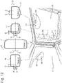
- Illustrated in Figure 12 are the locations of the various reference makers on the mirror surface as they would appear to the driver through the side door window 15 and the windscreen 17.
- the location of the aiming marker on the various mirror surfaces is restricted to a confined area.
- the aiming fifth marker 59 on the main (class II) rear view mirror 7 is best confined to a location not beyond a distance D of 20 mm from the inside edge, and not beyond 30 mm above or below the vertical center of the inside edge.
- the aiming sixth marker 61 on the wide-angle (class IV) rear view mirror 11 is again best located within a distance D of 20 mm from the inside edge, and not higher or lower than a spacing S of 10 mm from the vertical center of the inside edge.
- the location of the aiming markers, when restricted to these confined areas will enable use of position markers, or target markers on the cabin as described hereinabove. At the same time the aiming markers do not obstruct the field of vision to any obtrusive extent.
- the size of the aiming marker on the mirror surface is possibly small, but should be large enough, at least on the co-driver's side of the cabin to be easily discernible from the driver's side of the cabin.
- the aiming fifth, sixth, eighth and tenth markers 59, 61, 65, 69 should preferably be within a size range of a circular diameter or square size of 5 to 10 mm.
- the aiming second and third markers 43, 45 on the driver's side can be in accordance with the lower boundary of this 5-10 mm range.
- fourth, seventh and ninth markers 41, 57, 63, 67 it is preferred for these to provide reflected images in the respective mirrors within a circular or square size range of 10 to 20 mm, i.e. to be at least twice as large as the related aiming marker.
- a marker not only refers to passive markers, such as contrasting surface color indicia, patches or stickers, but also to active markers, such as illuminated markers, such pilot lights or LED's.
- Illuminated markers also need not be of an active variety, but can also include those of a passive variety, such reflective or irradiating markers. The latter variant of illuminated markers offers the additional benefit of enabling proper mirror adjustment in the dark, which is not yet available in any form and would be particularly beneficial to road traffic safety.
- illuminated markers When illuminated markers are used, it is also possible to guide a truck driver through the steps of mirror adjustment by illuminating only one mirror marker for aiming and one body marker for targeting at the time. Also it becomes possible with illuminated markers to couple these to the operation of remote mirror adjustment devices so that only those markers are lit that are relevant to the controls selected by the driver. Also when illuminated body target markers are used it becomes possible to obtain more readily recognizable reflections in the mirrors without having to use large surface areas on the truck cabin bodies.
- truck cabin may come in a great variety of colors, it may sometimes be necessary to enhance recognition to the cabin target marker by providing a border to the target marker that has a complementary color.
- a complementary colored border preferably has a width of 2.5 to 5 mm.
- markers may all have the same form such as circular, triangular or rectangular, but may also have different forms in accordance with their purpose to be more readily recognizable.
- a mirror adjustment assistance system for trucks having as part of a vehicle body at least a cabin 3 having a front side with respect to an intended main direction of travel, a driver side, and a co-driver side.
- At least three independently and individually adjustable mirrors 5, 7, 9, 11, 13, 19 are attached to an exterior of the cabin 3, each of these at least three adjustable mirrors 5, 7, 9, 11, 13, 19 has an aiming marker 43, 45, 59, 61, 65, 69 on or adjacent to its reflective surface.
- At least two vehicle body target markers 41, 57, 63, 67 are positioned on an exterior surface of the vehicle body 3, and at least a single one 41; 57 of these at least two vehicle body target markers is associated with two of the at least three mirrors 5, 9; 7, 11.
- any the aiming markers 43, 45, 59, 61, 65, 69 of the at least three adjustable mirrors 5, 7, 9, 11, 13, 19 can each only be aligned with a single one of the at least two vehicle target markers 41, 57, 63, 67.
Landscapes
- Engineering & Computer Science (AREA)
- Multimedia (AREA)
- Mechanical Engineering (AREA)
- Rear-View Mirror Devices That Are Mounted On The Exterior Of The Vehicle (AREA)
Claims (15)
- Assistenzsystem zur Spiegeleinstellung für LKW (1), das einschließt:als Teil einer Fahrzeugkarosserie wenigstens eine Kabine (3) mit einer Vorderseite in Bezug auf eine vorgesehene Hauptfahrrichtung, eine Fahrerseite und eine Beifahrerseite;einen einstellbaren Spiegel, der an einer Außenseite der Kabine (3) befestigt ist, wobei der einstellbare Spiegel eine Richtmarke auf oder neben seiner reflektierenden Oberfläche aufweist; undwenigstens eine Fahrzeugkarosserie-Zielmarke auf einer Außenfläche der Fahrzeugkarosserie,wobei die Fahrzeugkarosserie-Zielmarke dem einstellbaren Spiegel zugeordnet ist,dadurch gekennzeichnet, dass das Assistenzsystem zur Spiegeleinstellung wenigstens drei unabhängig einstellbare Spiegel (5, 7, 9, 11, 13, 19) umfasst, die an der Außenseite der Kabine (3) befestigt sind, wobei jeder der wenigstens drei einstellbaren Spiegel (5, 7, 9, 11, 13, 19) eine Richtmarke (43, 45, 59, 61, 65, 69) auf oder neben seiner reflektierenden Oberfläche aufweist; dadurch, dass das Assistenzsystem zur Spiegeleinstellung wenigstens eine Fahrzeugkarosserie-Zielmarke (41, 57) auf der Außenfläche der Fahrzeugkarosserie umfasst,dass eine einzige der wenigstens einen Fahrzeugkarosserie-Zielmarke (41, 57) zwei der wenigstens drei Spiegel (5, 9; 7, 11) zugeordnet ist, unddass jede Richtmarke (43, 45; 59, 61) der beiden der wenigstens drei einstellbaren Spiegel (5, 9; 7, 11) jeweils nur auf die einzige der wenigstens einen Fahrzeugkarosserie-Zielmarke (41, 57) ausgerichtet werden kann.
- Assistenzsystem zur Spiegeleinstellung nach Anspruch 1, wobei ein erster der beiden einstellbaren Spiegel ein Hauptrückspiegel (5, 7) ist und ein zweiter der beiden einstellbaren Spiegel ein Weitwinkel-Totwinkelspiegel (9, 11) ist, und wobei die eine der wenigstens zwei Fahrzeugkarosserie-Zielmarken (41, 57) die eine Fahrzeugkarosserie-Zielmarke ist, die dem Hauptrückspiegel (5, 7) und dem Weitwinkel-Totwinkelspiegel (9, 11) zur Ausrichtung mit den Richtmarken (43, 45, 59, 61) dieser Hauptrückspiegel (5, 7) und Weitwinkel-Totwinkelspiegel (9, 11) zugeordnet ist.
- Assistenzsystem zur Spiegeleinstellung nach Anspruch 2, wobei sich die wenigstens zwei Fahrzeugkarosserie-Zielmarken (41, 57) an einer hinteren Kante der Kabine (3) in Bezug auf die vorgesehene Hauptfahrrichtung befinden.
- Assistenzsystem zur Spiegeleinstellung nach Anspruch 2 oder 3, wobei sich der Hauptrückspiegel (7) und der Weitwinkel-Totwinkelspiegel (11) auf der Beifahrerseite befinden, wobei ein Drittel der wenigstens drei einstellbaren Spiegel auf der Beifahrerseite ein Nahbereichs-Bordsteinspiegel (13) ist, und wobei eine zweite der wenigstens zwei Fahrzeugkarosserie-Zielmarken so positioniert ist, dass sie ausschließlich mit dem Nahbereichs-Bordsteinspiegel (13) ausgerichtet werden kann.
- Assistenzsystem zur Spiegeleinstellung nach einem der Ansprüche 1 bis 4, wobei wenigstens zwei der wenigstens drei einstellbaren Spiegel elektrisch ferneinstellbar sind.
- Assistenzsystem zur Spiegeleinstellung nach einem der Ansprüche 1 bis 5, wobei wenigstens eine der Richtmarken (43, 45, 59, 61, 65, 69) und wenigstens eine zugeordnete Fahrzeugkarosserie-Zielmarke leicht erkennbare, mit dem Oberflächenbereich ihrer unmittelbaren Umgebung kontrastierende Zeichen sind.
- Assistenzsystem zur Spiegeleinstellung nach einem der Ansprüche 1 bis 5, wobei wenigstens eine der Fahrzeugkarosserie-Zielmarken eine dreidimensionale Struktur ist, die aus einem Oberflächenbereich der unmittelbaren Umgebung vorsteht.
- Assistenzsystem zur Spiegeleinstellung nach einem der Ansprüche 1 bis 7, wobei wenigstens eine der Richtmarken (43, 45, 59, 61, 65, 69) und/oder wenigstens eine zugeordnete Fahrzeugkarosserie-Zielmarke (41, 57, 63, 67) Leuchtmarken sind.
- Assistenzsystem zur Spiegeleinstellung nach Anspruch 8, wobei wenigstens einige der einstellbaren Spiegel (5, 7, 9, 11, 13, 19) ferneinstellbar sind, und wobei die Leuchtmarken auch von der Fernbedienung gesteuert werden.
- Assistenzsystem zur Spiegeleinstellung nach Anspruch 4 oder einem der Ansprüche 5 bis 9, wenn es von Anspruch 4 abhängig ist, ferner umfassend einen Hauptrückspiegel (5) und einen Weitwinkel-Totwinkelspiegel (9) auf der Fahrerseite der Kabine und eine einzelne zugeordnete Fahrzeugkarosserie-Zielmarke (41) auf der Fahrerseite zur Ausrichtung mit den Richtmarken (43, 45) des Hauptrückspiegels (5) und des Weitwinkel-Totwinkelspiegels (9) auf der Fahrerseite.
- Assistenzsystem zur Spiegeleinstellung nach Anspruch 10, wobei die Richtmarken (43, 45) nur mit der einzelnen zugeordneten Fahrzeugkarosserie-Zielmarke (41) ausgerichtet werden können.
- Assistenzsystem zur Spiegeleinstellung nach einem der Ansprüche 1 bis 11, ferner umfassend einen Totwinkel-Frontspiegel (19) auf der Beifahrerseite und eine zugeordnete Frontspiegel-Zielmarke (67), die auf der Außenseite der Fahrzeugkarosserie positioniert ist, um ausschließlich mit dem Totwinkel-Frontspiegel (19) ausgerichtet werden zu können.
- Assistenzsystem zur Spiegeleinstellung nach einem der Ansprüche 1 bis 12, wobei die Richtmarken (43, 45, 59, 61, 65, 69) jeweils innerhalb eines Abstands von 20 mm zu einer Oberflächekante des jeweiligen einstellbaren Spiegels liegen.
- Assistenzsystem zur Spiegeleinstellung nach einem der Ansprüche 1 bis 13, wobei die Richtmarken (43, 45, 59, 61, 65, 69) jeweils innerhalb von 30 mm von einem Mittelpunkt einer Oberflächekante des jeweiligen einstellbaren Spiegels beabstandet sind.
- Assistenzsystem zur Spiegeleinstellung nach Anspruch 14, wobei die Richtmarke (43, 45, 59, 61, 65, 69) wenigstens eines der wenigstens drei einstellbaren Spiegel (5, 7, 9, 11, 13, 19) innerhalb von 10 mm von dem Mittelpunkt der jeweiligen Oberflächekante beabstandet ist.
Applications Claiming Priority (2)
| Application Number | Priority Date | Filing Date | Title |
|---|---|---|---|
| NL2017200A NL2017200B1 (en) | 2016-07-20 | 2016-07-20 | Mirror adjustment assistance system for trucks |
| PCT/NL2017/050485 WO2018016951A1 (en) | 2016-07-20 | 2017-07-19 | Mirror adjustment assistance system for trucks |
Publications (2)
| Publication Number | Publication Date |
|---|---|
| EP3487729A1 EP3487729A1 (de) | 2019-05-29 |
| EP3487729B1 true EP3487729B1 (de) | 2022-04-13 |
Family
ID=57104129
Family Applications (1)
| Application Number | Title | Priority Date | Filing Date |
|---|---|---|---|
| EP17754814.6A Active EP3487729B1 (de) | 2016-07-20 | 2017-07-19 | Spiegelverstellhilfssystem für lastkraftwagen |
Country Status (6)
| Country | Link |
|---|---|
| US (1) | US11377030B2 (de) |
| EP (1) | EP3487729B1 (de) |
| BR (1) | BR112019001104A2 (de) |
| NL (1) | NL2017200B1 (de) |
| RU (1) | RU2714820C1 (de) |
| WO (1) | WO2018016951A1 (de) |
Families Citing this family (1)
| Publication number | Priority date | Publication date | Assignee | Title |
|---|---|---|---|---|
| JP2025141357A (ja) * | 2024-03-15 | 2025-09-29 | 株式会社クボタ | 作業車両 |
Citations (1)
| Publication number | Priority date | Publication date | Assignee | Title |
|---|---|---|---|---|
| DE4019234A1 (de) * | 1990-06-15 | 1991-12-19 | Man Nutzfahrzeuge Ag | Rueckspiegelanordnung |
Family Cites Families (8)
| Publication number | Priority date | Publication date | Assignee | Title |
|---|---|---|---|---|
| US4730926A (en) * | 1986-07-28 | 1988-03-15 | Lowell R. Wedemeyer | Accu-right mirror alignment system |
| US5022747A (en) | 1989-11-06 | 1991-06-11 | Polanyi Michael L | Device for adjusting automobile side view mirror |
| US5122910A (en) * | 1989-11-06 | 1992-06-16 | Polanyi Michael L | Device for adjusting automobile side view mirror |
| JP3799988B2 (ja) * | 2000-10-23 | 2006-07-19 | いすゞ自動車株式会社 | バックミラー装置 |
| US8200397B2 (en) * | 2008-07-16 | 2012-06-12 | GM Global Technology Operations LLC | Automatic rearview mirror adjustment system for vehicle |
| DE102009009379B3 (de) * | 2009-02-18 | 2010-07-01 | Mekra Lang Gmbh & Co. Kg | Spiegelanordnung für Fahrzeuge sowie Fahrzeug mit einer solchen Spiegelanordnung |
| JP6221703B2 (ja) * | 2013-12-05 | 2017-11-01 | いすゞ自動車株式会社 | 荷室全高目印器、貨物車両、及び貨物車両の荷室全高確認方法 |
| US9340157B2 (en) | 2014-02-11 | 2016-05-17 | Josef M. Sulc | Automotive mirror adjustment system |
-
2016
- 2016-07-20 NL NL2017200A patent/NL2017200B1/nl not_active IP Right Cessation
-
2017
- 2017-07-19 US US16/318,872 patent/US11377030B2/en active Active
- 2017-07-19 RU RU2019100631A patent/RU2714820C1/ru active
- 2017-07-19 EP EP17754814.6A patent/EP3487729B1/de active Active
- 2017-07-19 BR BR112019001104-8A patent/BR112019001104A2/pt not_active Application Discontinuation
- 2017-07-19 WO PCT/NL2017/050485 patent/WO2018016951A1/en not_active Ceased
Patent Citations (1)
| Publication number | Priority date | Publication date | Assignee | Title |
|---|---|---|---|---|
| DE4019234A1 (de) * | 1990-06-15 | 1991-12-19 | Man Nutzfahrzeuge Ag | Rueckspiegelanordnung |
Also Published As
| Publication number | Publication date |
|---|---|
| NL2017200B1 (en) | 2018-01-30 |
| BR112019001104A2 (pt) | 2019-04-30 |
| US20190241125A1 (en) | 2019-08-08 |
| WO2018016951A1 (en) | 2018-01-25 |
| US11377030B2 (en) | 2022-07-05 |
| EP3487729A1 (de) | 2019-05-29 |
| RU2714820C1 (ru) | 2020-02-19 |
Similar Documents
| Publication | Publication Date | Title |
|---|---|---|
| KR102649924B1 (ko) | 주변 센서 하우징 | |
| KR102665624B1 (ko) | 근접 감지 카메라 시스템 | |
| EP1867524B1 (de) | Vorrichtung zur Sichtunterstützung für ein Fahrzeug | |
| EP2431225B1 (de) | Verfahren zur Erkennung einer Automobilgefahr und Informationssystem | |
| US6198386B1 (en) | Vehicle guidance assembly and method | |
| US20060250224A1 (en) | Means of transport with a three-dimensional distance camera and method for the operation thereof | |
| US20150203026A1 (en) | Position and pathway lighting system for a vehicle or combination of vehicles sides undersides rear or trailing wheels and rear or trailing body portion | |
| US7817022B2 (en) | Vision enhancement device for use in vehicle | |
| DE102009048491A1 (de) | Nachrüstsystem für ein Fahrzeug, Nachrüstkomponente und Verfahren zum Durchführen einer Funktion zur Fahrerunterstützung | |
| US20200238908A1 (en) | Camera assembly for an industrial vehicle cab | |
| US7650698B2 (en) | Visual driving aid | |
| US20150224931A1 (en) | Automotive mirror adjustment system | |
| US11377030B2 (en) | Mirror adjustment assistance system for trucks | |
| CN114258358A (zh) | 车辆的视觉辅助工具 | |
| US20050099706A1 (en) | Driver observation system | |
| DE102010048347A1 (de) | Kraftfahrzeug-Außenspiegel mit Einparkscheinwerfer | |
| US20030016127A1 (en) | Directional display lamp for a vehicle | |
| US20260084620A1 (en) | Camera monitor system with projection displays | |
| CA3165284C (en) | Perimeter sensor housings | |
| JP2020185980A (ja) | 車両の旋回警告装置 | |
| HK40068393A (en) | Visualisation aid for a vehicle | |
| Niewoehner | How to Use Mirrors | |
| KR200387230Y1 (ko) | 자동차 백미러 | |
| US20130050859A1 (en) | Rearward and forward viewing vehicular mirror assembly | |
| CN111391757A (zh) | 汽车的外后视镜装置 |
Legal Events
| Date | Code | Title | Description |
|---|---|---|---|
| STAA | Information on the status of an ep patent application or granted ep patent |
Free format text: STATUS: UNKNOWN |
|
| STAA | Information on the status of an ep patent application or granted ep patent |
Free format text: STATUS: THE INTERNATIONAL PUBLICATION HAS BEEN MADE |
|
| PUAI | Public reference made under article 153(3) epc to a published international application that has entered the european phase |
Free format text: ORIGINAL CODE: 0009012 |
|
| STAA | Information on the status of an ep patent application or granted ep patent |
Free format text: STATUS: REQUEST FOR EXAMINATION WAS MADE |
|
| 17P | Request for examination filed |
Effective date: 20190121 |
|
| AK | Designated contracting states |
Kind code of ref document: A1 Designated state(s): AL AT BE BG CH CY CZ DE DK EE ES FI FR GB GR HR HU IE IS IT LI LT LU LV MC MK MT NL NO PL PT RO RS SE SI SK SM TR |
|
| AX | Request for extension of the european patent |
Extension state: BA ME |
|
| DAV | Request for validation of the european patent (deleted) | ||
| DAX | Request for extension of the european patent (deleted) | ||
| STAA | Information on the status of an ep patent application or granted ep patent |
Free format text: STATUS: EXAMINATION IS IN PROGRESS |
|
| 17Q | First examination report despatched |
Effective date: 20210311 |
|
| GRAP | Despatch of communication of intention to grant a patent |
Free format text: ORIGINAL CODE: EPIDOSNIGR1 |
|
| STAA | Information on the status of an ep patent application or granted ep patent |
Free format text: STATUS: GRANT OF PATENT IS INTENDED |
|
| GRAJ | Information related to disapproval of communication of intention to grant by the applicant or resumption of examination proceedings by the epo deleted |
Free format text: ORIGINAL CODE: EPIDOSDIGR1 |
|
| GRAP | Despatch of communication of intention to grant a patent |
Free format text: ORIGINAL CODE: EPIDOSNIGR1 |
|
| INTG | Intention to grant announced |
Effective date: 20211011 |
|
| RAP3 | Party data changed (applicant data changed or rights of an application transferred) |
Owner name: DAF TRUCKS N.V. |
|
| INTG | Intention to grant announced |
Effective date: 20211027 |
|
| GRAS | Grant fee paid |
Free format text: ORIGINAL CODE: EPIDOSNIGR3 |
|
| GRAA | (expected) grant |
Free format text: ORIGINAL CODE: 0009210 |
|
| STAA | Information on the status of an ep patent application or granted ep patent |
Free format text: STATUS: THE PATENT HAS BEEN GRANTED |
|
| AK | Designated contracting states |
Kind code of ref document: B1 Designated state(s): AL AT BE BG CH CY CZ DE DK EE ES FI FR GB GR HR HU IE IS IT LI LT LU LV MC MK MT NL NO PL PT RO RS SE SI SK SM TR |
|
| REG | Reference to a national code |
Ref country code: GB Ref legal event code: FG4D |
|
| REG | Reference to a national code |
Ref country code: CH Ref legal event code: EP |
|
| REG | Reference to a national code |
Ref country code: DE Ref legal event code: R096 Ref document number: 602017055929 Country of ref document: DE |
|
| REG | Reference to a national code |
Ref country code: NL Ref legal event code: FP |
|
| REG | Reference to a national code |
Ref country code: IE Ref legal event code: FG4D |
|
| REG | Reference to a national code |
Ref country code: AT Ref legal event code: REF Ref document number: 1483162 Country of ref document: AT Kind code of ref document: T Effective date: 20220515 |
|
| REG | Reference to a national code |
Ref country code: LT Ref legal event code: MG9D |
|
| REG | Reference to a national code |
Ref country code: AT Ref legal event code: MK05 Ref document number: 1483162 Country of ref document: AT Kind code of ref document: T Effective date: 20220413 |
|
| PG25 | Lapsed in a contracting state [announced via postgrant information from national office to epo] |
Ref country code: SE Free format text: LAPSE BECAUSE OF FAILURE TO SUBMIT A TRANSLATION OF THE DESCRIPTION OR TO PAY THE FEE WITHIN THE PRESCRIBED TIME-LIMIT Effective date: 20220413 Ref country code: PT Free format text: LAPSE BECAUSE OF FAILURE TO SUBMIT A TRANSLATION OF THE DESCRIPTION OR TO PAY THE FEE WITHIN THE PRESCRIBED TIME-LIMIT Effective date: 20220816 Ref country code: NO Free format text: LAPSE BECAUSE OF FAILURE TO SUBMIT A TRANSLATION OF THE DESCRIPTION OR TO PAY THE FEE WITHIN THE PRESCRIBED TIME-LIMIT Effective date: 20220713 Ref country code: LT Free format text: LAPSE BECAUSE OF FAILURE TO SUBMIT A TRANSLATION OF THE DESCRIPTION OR TO PAY THE FEE WITHIN THE PRESCRIBED TIME-LIMIT Effective date: 20220413 Ref country code: HR Free format text: LAPSE BECAUSE OF FAILURE TO SUBMIT A TRANSLATION OF THE DESCRIPTION OR TO PAY THE FEE WITHIN THE PRESCRIBED TIME-LIMIT Effective date: 20220413 Ref country code: GR Free format text: LAPSE BECAUSE OF FAILURE TO SUBMIT A TRANSLATION OF THE DESCRIPTION OR TO PAY THE FEE WITHIN THE PRESCRIBED TIME-LIMIT Effective date: 20220714 Ref country code: FI Free format text: LAPSE BECAUSE OF FAILURE TO SUBMIT A TRANSLATION OF THE DESCRIPTION OR TO PAY THE FEE WITHIN THE PRESCRIBED TIME-LIMIT Effective date: 20220413 Ref country code: ES Free format text: LAPSE BECAUSE OF FAILURE TO SUBMIT A TRANSLATION OF THE DESCRIPTION OR TO PAY THE FEE WITHIN THE PRESCRIBED TIME-LIMIT Effective date: 20220413 Ref country code: BG Free format text: LAPSE BECAUSE OF FAILURE TO SUBMIT A TRANSLATION OF THE DESCRIPTION OR TO PAY THE FEE WITHIN THE PRESCRIBED TIME-LIMIT Effective date: 20220713 Ref country code: AT Free format text: LAPSE BECAUSE OF FAILURE TO SUBMIT A TRANSLATION OF THE DESCRIPTION OR TO PAY THE FEE WITHIN THE PRESCRIBED TIME-LIMIT Effective date: 20220413 |
|
| PG25 | Lapsed in a contracting state [announced via postgrant information from national office to epo] |
Ref country code: RS Free format text: LAPSE BECAUSE OF FAILURE TO SUBMIT A TRANSLATION OF THE DESCRIPTION OR TO PAY THE FEE WITHIN THE PRESCRIBED TIME-LIMIT Effective date: 20220413 Ref country code: PL Free format text: LAPSE BECAUSE OF FAILURE TO SUBMIT A TRANSLATION OF THE DESCRIPTION OR TO PAY THE FEE WITHIN THE PRESCRIBED TIME-LIMIT Effective date: 20220413 Ref country code: LV Free format text: LAPSE BECAUSE OF FAILURE TO SUBMIT A TRANSLATION OF THE DESCRIPTION OR TO PAY THE FEE WITHIN THE PRESCRIBED TIME-LIMIT Effective date: 20220413 Ref country code: IS Free format text: LAPSE BECAUSE OF FAILURE TO SUBMIT A TRANSLATION OF THE DESCRIPTION OR TO PAY THE FEE WITHIN THE PRESCRIBED TIME-LIMIT Effective date: 20220813 |
|
| REG | Reference to a national code |
Ref country code: DE Ref legal event code: R097 Ref document number: 602017055929 Country of ref document: DE |
|
| PG25 | Lapsed in a contracting state [announced via postgrant information from national office to epo] |
Ref country code: SM Free format text: LAPSE BECAUSE OF FAILURE TO SUBMIT A TRANSLATION OF THE DESCRIPTION OR TO PAY THE FEE WITHIN THE PRESCRIBED TIME-LIMIT Effective date: 20220413 Ref country code: SK Free format text: LAPSE BECAUSE OF FAILURE TO SUBMIT A TRANSLATION OF THE DESCRIPTION OR TO PAY THE FEE WITHIN THE PRESCRIBED TIME-LIMIT Effective date: 20220413 Ref country code: RO Free format text: LAPSE BECAUSE OF FAILURE TO SUBMIT A TRANSLATION OF THE DESCRIPTION OR TO PAY THE FEE WITHIN THE PRESCRIBED TIME-LIMIT Effective date: 20220413 Ref country code: EE Free format text: LAPSE BECAUSE OF FAILURE TO SUBMIT A TRANSLATION OF THE DESCRIPTION OR TO PAY THE FEE WITHIN THE PRESCRIBED TIME-LIMIT Effective date: 20220413 Ref country code: DK Free format text: LAPSE BECAUSE OF FAILURE TO SUBMIT A TRANSLATION OF THE DESCRIPTION OR TO PAY THE FEE WITHIN THE PRESCRIBED TIME-LIMIT Effective date: 20220413 Ref country code: CZ Free format text: LAPSE BECAUSE OF FAILURE TO SUBMIT A TRANSLATION OF THE DESCRIPTION OR TO PAY THE FEE WITHIN THE PRESCRIBED TIME-LIMIT Effective date: 20220413 |
|
| PLBE | No opposition filed within time limit |
Free format text: ORIGINAL CODE: 0009261 |
|
| STAA | Information on the status of an ep patent application or granted ep patent |
Free format text: STATUS: NO OPPOSITION FILED WITHIN TIME LIMIT |
|
| PG25 | Lapsed in a contracting state [announced via postgrant information from national office to epo] |
Ref country code: MC Free format text: LAPSE BECAUSE OF FAILURE TO SUBMIT A TRANSLATION OF THE DESCRIPTION OR TO PAY THE FEE WITHIN THE PRESCRIBED TIME-LIMIT Effective date: 20220413 |
|
| REG | Reference to a national code |
Ref country code: CH Ref legal event code: PL |
|
| 26N | No opposition filed |
Effective date: 20230116 |
|
| REG | Reference to a national code |
Ref country code: BE Ref legal event code: MM Effective date: 20220731 |
|
| PG25 | Lapsed in a contracting state [announced via postgrant information from national office to epo] |
Ref country code: AL Free format text: LAPSE BECAUSE OF FAILURE TO SUBMIT A TRANSLATION OF THE DESCRIPTION OR TO PAY THE FEE WITHIN THE PRESCRIBED TIME-LIMIT Effective date: 20220413 |
|
| PG25 | Lapsed in a contracting state [announced via postgrant information from national office to epo] |
Ref country code: LU Free format text: LAPSE BECAUSE OF NON-PAYMENT OF DUE FEES Effective date: 20220719 Ref country code: LI Free format text: LAPSE BECAUSE OF NON-PAYMENT OF DUE FEES Effective date: 20220731 Ref country code: CH Free format text: LAPSE BECAUSE OF NON-PAYMENT OF DUE FEES Effective date: 20220731 |
|
| PG25 | Lapsed in a contracting state [announced via postgrant information from national office to epo] |
Ref country code: SI Free format text: LAPSE BECAUSE OF FAILURE TO SUBMIT A TRANSLATION OF THE DESCRIPTION OR TO PAY THE FEE WITHIN THE PRESCRIBED TIME-LIMIT Effective date: 20220413 Ref country code: BE Free format text: LAPSE BECAUSE OF NON-PAYMENT OF DUE FEES Effective date: 20220731 |
|
| P01 | Opt-out of the competence of the unified patent court (upc) registered |
Effective date: 20230525 |
|
| PG25 | Lapsed in a contracting state [announced via postgrant information from national office to epo] |
Ref country code: IE Free format text: LAPSE BECAUSE OF NON-PAYMENT OF DUE FEES Effective date: 20220719 |
|
| PG25 | Lapsed in a contracting state [announced via postgrant information from national office to epo] |
Ref country code: IT Free format text: LAPSE BECAUSE OF FAILURE TO SUBMIT A TRANSLATION OF THE DESCRIPTION OR TO PAY THE FEE WITHIN THE PRESCRIBED TIME-LIMIT Effective date: 20220413 |
|
| PG25 | Lapsed in a contracting state [announced via postgrant information from national office to epo] |
Ref country code: HU Free format text: LAPSE BECAUSE OF FAILURE TO SUBMIT A TRANSLATION OF THE DESCRIPTION OR TO PAY THE FEE WITHIN THE PRESCRIBED TIME-LIMIT; INVALID AB INITIO Effective date: 20170719 |
|
| PG25 | Lapsed in a contracting state [announced via postgrant information from national office to epo] |
Ref country code: MK Free format text: LAPSE BECAUSE OF FAILURE TO SUBMIT A TRANSLATION OF THE DESCRIPTION OR TO PAY THE FEE WITHIN THE PRESCRIBED TIME-LIMIT Effective date: 20220413 Ref country code: CY Free format text: LAPSE BECAUSE OF FAILURE TO SUBMIT A TRANSLATION OF THE DESCRIPTION OR TO PAY THE FEE WITHIN THE PRESCRIBED TIME-LIMIT Effective date: 20220413 |
|
| PG25 | Lapsed in a contracting state [announced via postgrant information from national office to epo] |
Ref country code: MT Free format text: LAPSE BECAUSE OF FAILURE TO SUBMIT A TRANSLATION OF THE DESCRIPTION OR TO PAY THE FEE WITHIN THE PRESCRIBED TIME-LIMIT Effective date: 20220413 |
|
| PG25 | Lapsed in a contracting state [announced via postgrant information from national office to epo] |
Ref country code: BG Free format text: LAPSE BECAUSE OF FAILURE TO SUBMIT A TRANSLATION OF THE DESCRIPTION OR TO PAY THE FEE WITHIN THE PRESCRIBED TIME-LIMIT Effective date: 20220413 |
|
| PG25 | Lapsed in a contracting state [announced via postgrant information from national office to epo] |
Ref country code: BG Free format text: LAPSE BECAUSE OF FAILURE TO SUBMIT A TRANSLATION OF THE DESCRIPTION OR TO PAY THE FEE WITHIN THE PRESCRIBED TIME-LIMIT Effective date: 20220413 |
|
| PGFP | Annual fee paid to national office [announced via postgrant information from national office to epo] |
Ref country code: NL Payment date: 20250721 Year of fee payment: 9 |
|
| PGFP | Annual fee paid to national office [announced via postgrant information from national office to epo] |
Ref country code: DE Payment date: 20250722 Year of fee payment: 9 |
|
| PGFP | Annual fee paid to national office [announced via postgrant information from national office to epo] |
Ref country code: GB Payment date: 20250722 Year of fee payment: 9 |
|
| PGFP | Annual fee paid to national office [announced via postgrant information from national office to epo] |
Ref country code: FR Payment date: 20250725 Year of fee payment: 9 |
|
| PG25 | Lapsed in a contracting state [announced via postgrant information from national office to epo] |
Ref country code: TR Free format text: LAPSE BECAUSE OF FAILURE TO SUBMIT A TRANSLATION OF THE DESCRIPTION OR TO PAY THE FEE WITHIN THE PRESCRIBED TIME-LIMIT Effective date: 20220413 |