EP3487455B1 - Modulare spacer vorrichtung für die gelenke des menschliche körpers - Google Patents
Modulare spacer vorrichtung für die gelenke des menschliche körpers Download PDFInfo
- Publication number
- EP3487455B1 EP3487455B1 EP17748573.7A EP17748573A EP3487455B1 EP 3487455 B1 EP3487455 B1 EP 3487455B1 EP 17748573 A EP17748573 A EP 17748573A EP 3487455 B1 EP3487455 B1 EP 3487455B1
- Authority
- EP
- European Patent Office
- Prior art keywords
- spacer device
- femoral
- tibial
- modular spacer
- curvature radius
- Prior art date
- Legal status (The legal status is an assumption and is not a legal conclusion. Google has not performed a legal analysis and makes no representation as to the accuracy of the status listed.)
- Active
Links
Images


Classifications
-
- A—HUMAN NECESSITIES
- A61—MEDICAL OR VETERINARY SCIENCE; HYGIENE
- A61F—FILTERS IMPLANTABLE INTO BLOOD VESSELS; PROSTHESES; DEVICES PROVIDING PATENCY TO, OR PREVENTING COLLAPSING OF, TUBULAR STRUCTURES OF THE BODY, e.g. STENTS; ORTHOPAEDIC, NURSING OR CONTRACEPTIVE DEVICES; FOMENTATION; TREATMENT OR PROTECTION OF EYES OR EARS; BANDAGES, DRESSINGS OR ABSORBENT PADS; FIRST-AID KITS
- A61F2/00—Filters implantable into blood vessels; Prostheses, i.e. artificial substitutes or replacements for parts of the body; Appliances for connecting them with the body; Devices providing patency to, or preventing collapsing of, tubular structures of the body, e.g. stents
- A61F2/02—Prostheses implantable into the body
- A61F2/30—Joints
- A61F2/38—Joints for elbows or knees
- A61F2/3886—Joints for elbows or knees for stabilising knees against anterior or lateral dislocations
-
- A—HUMAN NECESSITIES
- A61—MEDICAL OR VETERINARY SCIENCE; HYGIENE
- A61F—FILTERS IMPLANTABLE INTO BLOOD VESSELS; PROSTHESES; DEVICES PROVIDING PATENCY TO, OR PREVENTING COLLAPSING OF, TUBULAR STRUCTURES OF THE BODY, e.g. STENTS; ORTHOPAEDIC, NURSING OR CONTRACEPTIVE DEVICES; FOMENTATION; TREATMENT OR PROTECTION OF EYES OR EARS; BANDAGES, DRESSINGS OR ABSORBENT PADS; FIRST-AID KITS
- A61F2/00—Filters implantable into blood vessels; Prostheses, i.e. artificial substitutes or replacements for parts of the body; Appliances for connecting them with the body; Devices providing patency to, or preventing collapsing of, tubular structures of the body, e.g. stents
- A61F2/02—Prostheses implantable into the body
- A61F2/30—Joints
- A61F2/38—Joints for elbows or knees
- A61F2/3859—Femoral components
-
- A—HUMAN NECESSITIES
- A61—MEDICAL OR VETERINARY SCIENCE; HYGIENE
- A61F—FILTERS IMPLANTABLE INTO BLOOD VESSELS; PROSTHESES; DEVICES PROVIDING PATENCY TO, OR PREVENTING COLLAPSING OF, TUBULAR STRUCTURES OF THE BODY, e.g. STENTS; ORTHOPAEDIC, NURSING OR CONTRACEPTIVE DEVICES; FOMENTATION; TREATMENT OR PROTECTION OF EYES OR EARS; BANDAGES, DRESSINGS OR ABSORBENT PADS; FIRST-AID KITS
- A61F2/00—Filters implantable into blood vessels; Prostheses, i.e. artificial substitutes or replacements for parts of the body; Appliances for connecting them with the body; Devices providing patency to, or preventing collapsing of, tubular structures of the body, e.g. stents
- A61F2/02—Prostheses implantable into the body
- A61F2/30—Joints
- A61F2/38—Joints for elbows or knees
- A61F2/3836—Special connection between upper and lower leg, e.g. constrained
-
- A—HUMAN NECESSITIES
- A61—MEDICAL OR VETERINARY SCIENCE; HYGIENE
- A61F—FILTERS IMPLANTABLE INTO BLOOD VESSELS; PROSTHESES; DEVICES PROVIDING PATENCY TO, OR PREVENTING COLLAPSING OF, TUBULAR STRUCTURES OF THE BODY, e.g. STENTS; ORTHOPAEDIC, NURSING OR CONTRACEPTIVE DEVICES; FOMENTATION; TREATMENT OR PROTECTION OF EYES OR EARS; BANDAGES, DRESSINGS OR ABSORBENT PADS; FIRST-AID KITS
- A61F2/00—Filters implantable into blood vessels; Prostheses, i.e. artificial substitutes or replacements for parts of the body; Appliances for connecting them with the body; Devices providing patency to, or preventing collapsing of, tubular structures of the body, e.g. stents
- A61F2/02—Prostheses implantable into the body
- A61F2/30—Joints
- A61F2/38—Joints for elbows or knees
- A61F2/389—Tibial components
-
- A—HUMAN NECESSITIES
- A61—MEDICAL OR VETERINARY SCIENCE; HYGIENE
- A61F—FILTERS IMPLANTABLE INTO BLOOD VESSELS; PROSTHESES; DEVICES PROVIDING PATENCY TO, OR PREVENTING COLLAPSING OF, TUBULAR STRUCTURES OF THE BODY, e.g. STENTS; ORTHOPAEDIC, NURSING OR CONTRACEPTIVE DEVICES; FOMENTATION; TREATMENT OR PROTECTION OF EYES OR EARS; BANDAGES, DRESSINGS OR ABSORBENT PADS; FIRST-AID KITS
- A61F2/00—Filters implantable into blood vessels; Prostheses, i.e. artificial substitutes or replacements for parts of the body; Appliances for connecting them with the body; Devices providing patency to, or preventing collapsing of, tubular structures of the body, e.g. stents
- A61F2/02—Prostheses implantable into the body
- A61F2/30—Joints
- A61F2002/30001—Additional features of subject-matter classified in A61F2/28, A61F2/30 and subgroups thereof
- A61F2002/30003—Material related properties of the prosthesis or of a coating on the prosthesis
- A61F2002/3006—Properties of materials and coating materials
-
- A—HUMAN NECESSITIES
- A61—MEDICAL OR VETERINARY SCIENCE; HYGIENE
- A61F—FILTERS IMPLANTABLE INTO BLOOD VESSELS; PROSTHESES; DEVICES PROVIDING PATENCY TO, OR PREVENTING COLLAPSING OF, TUBULAR STRUCTURES OF THE BODY, e.g. STENTS; ORTHOPAEDIC, NURSING OR CONTRACEPTIVE DEVICES; FOMENTATION; TREATMENT OR PROTECTION OF EYES OR EARS; BANDAGES, DRESSINGS OR ABSORBENT PADS; FIRST-AID KITS
- A61F2/00—Filters implantable into blood vessels; Prostheses, i.e. artificial substitutes or replacements for parts of the body; Appliances for connecting them with the body; Devices providing patency to, or preventing collapsing of, tubular structures of the body, e.g. stents
- A61F2/02—Prostheses implantable into the body
- A61F2/30—Joints
- A61F2002/30001—Additional features of subject-matter classified in A61F2/28, A61F2/30 and subgroups thereof
- A61F2002/30108—Shapes
- A61F2002/3011—Cross-sections or two-dimensional shapes
- A61F2002/30112—Rounded shapes, e.g. with rounded corners
-
- A—HUMAN NECESSITIES
- A61—MEDICAL OR VETERINARY SCIENCE; HYGIENE
- A61F—FILTERS IMPLANTABLE INTO BLOOD VESSELS; PROSTHESES; DEVICES PROVIDING PATENCY TO, OR PREVENTING COLLAPSING OF, TUBULAR STRUCTURES OF THE BODY, e.g. STENTS; ORTHOPAEDIC, NURSING OR CONTRACEPTIVE DEVICES; FOMENTATION; TREATMENT OR PROTECTION OF EYES OR EARS; BANDAGES, DRESSINGS OR ABSORBENT PADS; FIRST-AID KITS
- A61F2/00—Filters implantable into blood vessels; Prostheses, i.e. artificial substitutes or replacements for parts of the body; Appliances for connecting them with the body; Devices providing patency to, or preventing collapsing of, tubular structures of the body, e.g. stents
- A61F2/02—Prostheses implantable into the body
- A61F2/30—Joints
- A61F2002/30001—Additional features of subject-matter classified in A61F2/28, A61F2/30 and subgroups thereof
- A61F2002/30316—The prosthesis having different structural features at different locations within the same prosthesis; Connections between prosthetic parts; Special structural features of bone or joint prostheses not otherwise provided for
- A61F2002/30535—Special structural features of bone or joint prostheses not otherwise provided for
- A61F2002/30604—Special structural features of bone or joint prostheses not otherwise provided for modular
-
- A—HUMAN NECESSITIES
- A61—MEDICAL OR VETERINARY SCIENCE; HYGIENE
- A61F—FILTERS IMPLANTABLE INTO BLOOD VESSELS; PROSTHESES; DEVICES PROVIDING PATENCY TO, OR PREVENTING COLLAPSING OF, TUBULAR STRUCTURES OF THE BODY, e.g. STENTS; ORTHOPAEDIC, NURSING OR CONTRACEPTIVE DEVICES; FOMENTATION; TREATMENT OR PROTECTION OF EYES OR EARS; BANDAGES, DRESSINGS OR ABSORBENT PADS; FIRST-AID KITS
- A61F2/00—Filters implantable into blood vessels; Prostheses, i.e. artificial substitutes or replacements for parts of the body; Appliances for connecting them with the body; Devices providing patency to, or preventing collapsing of, tubular structures of the body, e.g. stents
- A61F2/02—Prostheses implantable into the body
- A61F2/30—Joints
- A61F2002/30001—Additional features of subject-matter classified in A61F2/28, A61F2/30 and subgroups thereof
- A61F2002/30667—Features concerning an interaction with the environment or a particular use of the prosthesis
- A61F2002/30672—Features concerning an interaction with the environment or a particular use of the prosthesis temporary
-
- A—HUMAN NECESSITIES
- A61—MEDICAL OR VETERINARY SCIENCE; HYGIENE
- A61F—FILTERS IMPLANTABLE INTO BLOOD VESSELS; PROSTHESES; DEVICES PROVIDING PATENCY TO, OR PREVENTING COLLAPSING OF, TUBULAR STRUCTURES OF THE BODY, e.g. STENTS; ORTHOPAEDIC, NURSING OR CONTRACEPTIVE DEVICES; FOMENTATION; TREATMENT OR PROTECTION OF EYES OR EARS; BANDAGES, DRESSINGS OR ABSORBENT PADS; FIRST-AID KITS
- A61F2/00—Filters implantable into blood vessels; Prostheses, i.e. artificial substitutes or replacements for parts of the body; Appliances for connecting them with the body; Devices providing patency to, or preventing collapsing of, tubular structures of the body, e.g. stents
- A61F2/02—Prostheses implantable into the body
- A61F2/30—Joints
- A61F2002/30001—Additional features of subject-matter classified in A61F2/28, A61F2/30 and subgroups thereof
- A61F2002/30667—Features concerning an interaction with the environment or a particular use of the prosthesis
- A61F2002/30677—Means for introducing or releasing pharmaceutical products, e.g. antibiotics, into the body
-
- A—HUMAN NECESSITIES
- A61—MEDICAL OR VETERINARY SCIENCE; HYGIENE
- A61F—FILTERS IMPLANTABLE INTO BLOOD VESSELS; PROSTHESES; DEVICES PROVIDING PATENCY TO, OR PREVENTING COLLAPSING OF, TUBULAR STRUCTURES OF THE BODY, e.g. STENTS; ORTHOPAEDIC, NURSING OR CONTRACEPTIVE DEVICES; FOMENTATION; TREATMENT OR PROTECTION OF EYES OR EARS; BANDAGES, DRESSINGS OR ABSORBENT PADS; FIRST-AID KITS
- A61F2/00—Filters implantable into blood vessels; Prostheses, i.e. artificial substitutes or replacements for parts of the body; Appliances for connecting them with the body; Devices providing patency to, or preventing collapsing of, tubular structures of the body, e.g. stents
- A61F2/02—Prostheses implantable into the body
- A61F2/30—Joints
- A61F2/30767—Special external or bone-contacting surface, e.g. coating for improving bone ingrowth
- A61F2/30771—Special external or bone-contacting surface, e.g. coating for improving bone ingrowth applied in original prostheses, e.g. holes or grooves
- A61F2002/30878—Special external or bone-contacting surface, e.g. coating for improving bone ingrowth applied in original prostheses, e.g. holes or grooves with non-sharp protrusions, for instance contacting the bone for anchoring, e.g. keels, pegs, pins, posts, shanks, stems, struts
-
- A—HUMAN NECESSITIES
- A61—MEDICAL OR VETERINARY SCIENCE; HYGIENE
- A61F—FILTERS IMPLANTABLE INTO BLOOD VESSELS; PROSTHESES; DEVICES PROVIDING PATENCY TO, OR PREVENTING COLLAPSING OF, TUBULAR STRUCTURES OF THE BODY, e.g. STENTS; ORTHOPAEDIC, NURSING OR CONTRACEPTIVE DEVICES; FOMENTATION; TREATMENT OR PROTECTION OF EYES OR EARS; BANDAGES, DRESSINGS OR ABSORBENT PADS; FIRST-AID KITS
- A61F2310/00—Prostheses classified in A61F2/28 or A61F2/30 - A61F2/44 being constructed from or coated with a particular material
- A61F2310/00005—The prosthesis being constructed from a particular material
- A61F2310/00011—Metals or alloys
-
- A—HUMAN NECESSITIES
- A61—MEDICAL OR VETERINARY SCIENCE; HYGIENE
- A61F—FILTERS IMPLANTABLE INTO BLOOD VESSELS; PROSTHESES; DEVICES PROVIDING PATENCY TO, OR PREVENTING COLLAPSING OF, TUBULAR STRUCTURES OF THE BODY, e.g. STENTS; ORTHOPAEDIC, NURSING OR CONTRACEPTIVE DEVICES; FOMENTATION; TREATMENT OR PROTECTION OF EYES OR EARS; BANDAGES, DRESSINGS OR ABSORBENT PADS; FIRST-AID KITS
- A61F2310/00—Prostheses classified in A61F2/28 or A61F2/30 - A61F2/44 being constructed from or coated with a particular material
- A61F2310/00005—The prosthesis being constructed from a particular material
- A61F2310/00179—Ceramics or ceramic-like structures
-
- A—HUMAN NECESSITIES
- A61—MEDICAL OR VETERINARY SCIENCE; HYGIENE
- A61F—FILTERS IMPLANTABLE INTO BLOOD VESSELS; PROSTHESES; DEVICES PROVIDING PATENCY TO, OR PREVENTING COLLAPSING OF, TUBULAR STRUCTURES OF THE BODY, e.g. STENTS; ORTHOPAEDIC, NURSING OR CONTRACEPTIVE DEVICES; FOMENTATION; TREATMENT OR PROTECTION OF EYES OR EARS; BANDAGES, DRESSINGS OR ABSORBENT PADS; FIRST-AID KITS
- A61F2310/00—Prostheses classified in A61F2/28 or A61F2/30 - A61F2/44 being constructed from or coated with a particular material
- A61F2310/00005—The prosthesis being constructed from a particular material
- A61F2310/00353—Bone cement, e.g. polymethylmethacrylate or PMMA
Definitions
- the present invention refers to a modular spacer device for the temporary substitution of joint prostheses that must be removed, for example following an infection. More particularly, the present invention refers to a spacer device for the knee joint.
- joint prostheses can be susceptible of removal for various reasons, in particular for local infections of the joint after the implant of the prosthesis.
- Temporary articular spacer devices for the knee are known, manually made by the surgeon during the spacer implant surgical operation.
- Such spacer devices are made of bone cement and are suitably shaped, in a manual manner, immediately before the implant in the articular seat.
- the manually-shaped articulated spacer devices suffer from several drawbacks.
- the manual process of making the spacer device during the operating session considerably lengthens the duration of the session itself and places the healthcare workers in direct contact with potentially toxic substances used for making the spacer device.
- the articular spacer device formed manually can have shape defects that can limit the mobility of the joint.
- the present invention therefore proposes the technical task of improving the state of the art with regard to the spacer devices for joints of the human body, in particular for the knee joint.
- one object of the present invention is to provide a spacer device for the knee joint which is preformed and which is adapted to the anthropomorphic sizes of each patient to whom it is applied.
- a further object of the present invention is to provide a spacer device for the knee joint which is capable of allowing a more suitable and stable movement of the joint with respect to the spacer devices of conventional type.
- Another object of the present invention is to provide a spacer device for the knee joint capable of offering greater resistance to lateral thrusts with respect to the spacer devices of conventional type.
- Patent document US 2013/006373 discloses a spacer device for the knee joint according to the preamble of claim 1.
- a spacer device for the knee joint is provided according to claim 1.
- a modular spacer device for the knee joint is generically indicated with reference number 1 and comprises at least one tibial element 2, adapted to be constrained to the tibial bone of a patient, at one end of such bone facing the knee joint, and at least one femoral element 3, in turn adapted to be constrained to the femoral bone of the patient, at an end thereof facing the knee joint, and articulated on said tibial element 2.
- the tibial element 2 comprises a first surface 21 facing, during use, the femoral element 3 and a second surface 22 opposite thereto.
- the femoral element 3 has a first surface 31 facing, during use, the respective tibial element 2, and a second surface 32 opposite thereto.
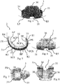
- the femoral element 3 as is known, has a substantially C-shaped plan configuration (see figure 8 ), in which each free end of the "C" corresponds with a rear lobe 33, 34 of the femoral element 3.
- the first surface 31 of the femoral element 3 is convex and laterally has (reference is made in particular to figure 5 ) a curved contour of "ammonite" type, in which the curvature radius increases starting from at least one rear section PS having curvature radius R1, towards at least one first central section FCS with curvature radius R2 and at least one second central section SCS with curvature radius R3, up to at least one front section FS of the femoral component 3, which has a curvature radius R4, with R1 ⁇ R2 ⁇ R3 ⁇ R4.
- the front section FS of the femoral element 3 frontally has (see the enclosed figures 4 and 6 ) a substantially curved lower contour LP, more particularly convex, according to a curvature radius R5.
- the first surface 31 of the femoral element 3 also delimits a central groove 35, extended according to an anteroposterior direction of the femoral element 3, i.e. starting from the front section FS towards the second central section SCS and the first central section FCS of the first surface.
- Such central groove 35 has a rounded contour. In other words, at such groove 35, the first surface 31 does not have linear or angular progression.
- the front section FS of the femoral element 3 has, seen frontally (see figure 4 ), an upper contour 36 substantially curved according to a substantially bell-shaped pattern.
- the upper contour 36 of the front section FS of the femoral element 3 has a tilted contour, sloping to the left (as is visible for example in figure 15 ) or to the right.
- the femoral element 3 of the modular spacer device 1 according to the present invention can be adapted respectively for a left knee or for a right knee.
- Such femoral component 3 can be coupled, as will be better indicated hereinbelow, to a left, right or symmetric tibial element 2.
- the second surface 32 of the femoral element 2 of the modular spacer device 1 is concave and laterally has (reference is made to figure 5 in particular) a curved U-shaped contour comprising at least one rear portion PP and one front portion AP parallel to each other, a base portion BP, substantially orthogonal to said rear portion PP and to said front portion AP, a rear connecting portion PCP, between said rear portion PP and said base portion BP, as well as a front connecting portion ACP, between said front portion AP and said base portion BP.
- the rear connecting portion PCP and the front connecting portion ACP can be curved or they can have substantially rectilinear configuration and are arranged, in the latter case, obliquely with respect to the portions to which they are respectively connected.
- each of the rear lobes 33 and 34 of the femoral element 3 is delimited between at least one rear portion PP and one rear connecting portion PCP of the second surface 32 and at least one rear section PS with curvature radius R1 and a first central section FCS with curvature radius R2 of the first surface 31 of the femoral element 3.
- the femoral element 3 of the modular spacer device 1 has an element in relief or central rib 37 with anteroposterior development, at the base portion BP and at the front connecting portion ACP on the second surface 32.
- Such central rib 37 is arranged at the central groove 35 made on the first surface 31 of the femoral element 3.
- the central rib 37 like the corresponding central groove 35, also has a rounded contour. In other words, at the central rib 37, the second surface 32 does not have linear or angular development.
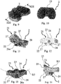
- this has a substantially reversed-"U" plan configuration (see figure 10 ), in which the base portion of the "U” corresponds to a front portion (front during use) 23 of the tibial element 2 and has a substantially rectilinear pattern.
- the first surface 21 of the tibial element 2 is concave and laterally has (reference is made to figure 14 ) a curved contour, more particularly concave, substantially complementary to the pattern of the second central section SCS with curvature radius R3 of the corresponding femoral component 3.
- the first surface 21 can frontally have a substantially flat or concave contour 24, though with very large curvature radius (e.g. much larger than R5) such to make it appear substantially flat. Also in such version, the first surface 21 acts as a support and is articulated with the substantially curved lower contour LP with curvature radius R5 of the femoral element 3.
- the first surface 21 can have a contour 24 of non-symmetric type, in the sense that the contour 24, in its medial portion, can have a concave pattern and in its lateral portion can have a flat contour, or vice versa, in accordance with the specific anatomic needs of the patient.
- the tibial element 2 has a "left" or "right” contour in accordance with the location of the concave portion. In all cases, the contour 24 allows the abutment and the articulation with the substantially curved lower contour LP with curvature radius R5 of the femoral element 3.
- the first surface 21 of the tibial element 2 delimits a relief portion or central rib 25 with rounded contour (as in the sense described above with reference to the central groove 35 and the central rib 37 of the femoral element).
- Such relief portion or central rib 25 is extended according to an anteroposterior direction in the tibial element 2 and has a configuration such to be substantially insertable to size in a corresponding central groove 35 delimited in the femoral element 3.
- the rib 25 of the tibial element 2 projects upward or stands out from the rest of the first surface 21 in a very pronounced manner, for example it projects upward for about 0.8-1.2 cm with respect thereto or, more preferably, for about 10 mm.
- the rib 25 can be higher, up to and over 20 mm.
- the central rib 25 acts as a stabilizer means in the sense that it prevents lateral movements between the femoral element 3 and the tibial element 2, once they have been coupled together as described above.
- the central rib 25 and the central groove 35 are sized in a manner such that there is a certain clearance between them, such that the femoral element 3 can be moved, in the sense that will be clearer hereinbelow, in anteroposterior direction with respect to the tibial element 2.
- the man skilled in the art will have no difficulty in understanding that the femoral element of the modular spacer device 1 according to the invention can be articulated on the corresponding tibial element 2. Indeed, the femoral element 3, more particularly its convex first surface 31, during use can roll and partially translate with respect to the concave first surface 21 of the tibial element 2, even if maintaining a high lateral stability due to the particular sizing of the central rib 25 and of the corresponding central groove 35.
- Such rolling and partially translational motion is due to the configuration of "ammonite" type of the femoral element 3 and of the corresponding configuration of the tibial element 2.
- this has the second surface 22 substantially flat and connected (in any suitable manner), in a central region corresponding to the central rib 25 of the first surface 21, to an engagement means 26.
- Such engagement means 26 is employed for engaging the tibial element 2 to a bone end of a patient.
- the modular spacer device optionally comprises at least one stem 4 engageable, for example via shape coupling, with the tibial element 2 at the engagement means 26.
- the engagement means 26 is a sleeve element, fixed to the second surface 22 of the tibial element 2 with its longitudinal symmetry axis substantially orthogonal to such surface 22. In this manner, the sleeve element delimits a housing seat 26a for one end of the stem 4.
- the tibial element 2 also comprises a plurality of reinforcement tabs 27 (see figures 11 to 14 ) between the second surface 22 and the sleeve element 26, designated to make the structure itself of the tibial element 2 more rigid.
- the stem 4 has a first end 41, insertable to size in the seat 26a delimited by the engagement means or sleeve 26, and has a longitudinal pattern tapered towards the other end 42 thereof, intended to be inserted, if provided, in the tibial bone cavity of a patient.
- both the femoral element 3 and the tibial element 2 can have plan extension that differs in accordance with the various predetermined formats or sizes, but they also maintain the configuration - i.e. the size and shape - constant (i.e. independent of the format or size) respectively of the central groove 35 and of the central rib 25, and/or of the curvature radii R3 and R5.
- the tibial element 2 and the femoral element 3 of the modular spacer device according to the invention can always be coupled together at the respective first surfaces 21 and 31, independent of the respective formats or respective sizes.
- the central rib 25 of the tibial element 2 and the central groove 35 of the femoral element are configured in a manner such that, if during the movement of the knee joint the device sustains lateral thrust stresses, the central rib 25 maintains the femoral element 3 in the seat, ensuring a correct movement and a good stability of the articulation.
- the lateral stability of the modular spacer device is furthermore also due to the particular convex or "ammonite" contour of the first surface 31 of the femoral element 3 and due to the corresponding concave or “sunken” contour of the corresponding first surface 21 of the femoral element.
- Their particular configuration, together with the configuration of the central rib 25, which is raised with respect to the rest of the first surface 21 in a much more pronounced manner with respect to the devices of conventional type, ensures that the femoral stress forces result in a self-centering moment, i.e. of longitudinal alignment between the femoral element 3 and the tibial element 2, hence offering a resistance to the lateral forces that is decidedly higher with respect to the modular spacer devices of conventional type.
- the different formats or sizes of the tibial element 2 and of the femoral element 3 are interchangeable with respect to each other, due to the equivalence of the curvature radii R3 and R5 of the first surfaces 31 and 21 and/or since the first surfaces 31 and 21 can be coupled together.
- Such modularity of the spacer device 1 therefore allows adapting it to the anthropomorphic sizes of the femoral and tibial ends of each patient, which can be different from each other.
- the configuration of the curvature radii R3 and R5 allows obtaining a relative main rolling motion between the femoral element 3 and the tibial element 2 as well as a partial sliding motion therebetween.
- Such main rolling motion between the first surface 31 of the femoral element 3 and the first upper surface 21 of the tibial element 2 allows the patient to complete a bending and extension movement of the articulation similar to the normal physiological movement of the knee joint.
- the man skilled in the art will have no difficulty observing that, in order to be able to adapt the modular spacer device 1 to the sizes of each patient, the surgeon is not required to carry out any manual modification operation for the femoral element 3 and the tibial element 2, thus reducing the times necessary for the implant of the modular spacer device 1. Indeed, the surgeon is only requested to select, from among the various available formats and sizes and for each element that composes the modular spacer device 1, the size or format that is best adapted to the actual size of the respective anatomic seat of the patient, without having to use a tibial element and a femoral element of the same size.
- the femoral element 3, the tibial element 2 and the stem 4 will be packaged in separate packages and in a single size.
- the tibial element 2 and the stem 4 always maintain constant (independent of their format or size) the configuration - i.e. the size and shape - respectively of the engagement means 26 (in particular the housing seat 26a) and of the connection end 41.
- the tibial element 2 and the stem 4 can be coupled together, independent of the plan extension of the tibial element 2 and of the cross section of the stem 4.
- the femoral element 3 is shaped in a manner such to be coupled with any size of the tibial element 2 in order to adapt the sizes of the modular spacer device with the sizes of the bone ends to which it must be connected.
- the surgeon will have a wide selection of formats for the femoral element 3 and the tibial element 2 and will not be obliged to select femoral and tibial elements of the same format or size. In addition, the selection will be even greater given the possibility of deciding whether he/she wishes to use the stem 4 or not.
- the above-described modular spacer device allows obtaining a high mobility of the knee joint and a movement similar to that of a natural articulation, even in the presence of different anatomic sizes, between the different articular portions of a patient.
- the bas-relief zones are present both on the tibial element 2 and on the femoral element 3 and are respectively indicated with the reference numbers 38 and 28.
- Such bas-relief zones 38 and/or 28 provided on the femoral element 3 and/or on the tibial element 2 are provided for facilitating the adhesion of the respective femoral component 3 and/or tibial component 2 to the corresponding bone end, by means of the use of a filling material, specifically bone cement and/or any other suitable material, during the surgical procedure of implant of the modular spacer device 1.
- the arrangement thereof can vary as a function of specific needs, for example as a function of the format or size of the femoral element 3 and of the tibial element 2.
- the bas-relief zones 38 and/or 28 form seats for housing a filling material as stated above, which - according to one aspect of the present invention - can be self-hardening or solidifiable.
- the filling material can be prepared by the surgeon during the operating procedure and/or it can lack pharmaceutical or medical substances and/or it can be admixed therewith based on the selection of the surgeon and on the needs of the patient.
- the bas-relief zones 38 and/or 28 in practice act as a tank for storing such pharmaceutical or medical substance to be released within the human body, more particularly in the bone or articular seat where the modular spacer device 1 is implanted.
- the pharmaceutical or medical substance, such as at least one antibiotic, inserted in the filling material is of soluble type, and therefore is released towards the bone tissue adjacent to or in contact with the filling material in order to heal or at least prevent the infection thereof.
- the filling material is non-reabsorbable or non-degradable in the human body at least for the stay time of the spacer device within the human body itself.
- the filling material is thus permanent.
- the filling material is applied by the surgeon before the implant of the modular spacer device itself.
- the aforesaid filling material can thus comprise at least one pharmaceutical or medical substance already arranged in the material, which constitutes the filling material itself, and it may, in preparation step, be admixed with a further substance.
- the filling material by virtue of the step of preparation or solidification to which it is subjected, can be porous.
- the size of the pores of the filling material is, in any case, such to prevent bone growth from occurring within the same during use, and hence to prevent such growth within the modular spacer device 1 according to the invention, which as stated is temporary.
- One such configuration of the pores therefore facilitates the subsequent removal of the spacer device itself from the treated bone or articular seat, once its treatment function as been completed.
- the pores can have, in one version, average size of less than 100 micron.
- the spacer device 1 is configured in a manner such that when, during use, it is implanted in the human body, the filling material in the bas-relief zones 38 and/or 28 is in contact with the bone tissues to be treated.
- the filling material is flush with the respective second surface 32 and/or 22 of the respective femoral element 3 or tibial element 2.
- the filling material exits from the respective bas-relief zone 38 and/or 28 and therefore projects with respect to the second surface 32 and/or 22 of the respective femoral element 3 or tibial element 2.
- the overall volume of the bas-relief zones 38 and/or 28 respectively on the femoral element 3 and/or on the tibial element 2 and the quantity of filling material is thus suitable for the time period estimated for treating the infection underway in the seat where the modular spacer device 1 according to the invention is implanted.
- the bas-relief zones 38 and/or 28 define, along the respective second surfaces 32 and 22, an open-cell structure.
- the open-cell structure comprises a plurality of cells side-by-side each other, each corresponding with a bas-relief zone 38 and/or 28.
- the bas-relief zones 38 and/or 28 are adjacent to each other on the respective femoral 3 and/or tibial elements 2.
- the cells can be more or less spaced from each other depending on the format of the respective femoral element 3 or tibial element 2 and in a manner such that these are not situated at portions of the device that, during use, are subjected to greater mechanical stresses, for example wear, bending, fatigue, etc.
- each bas-relief zone 38 and/or 28 is much greater than the respective depth. In such a manner, among other things, the surgeon will be facilitated in the application of the above-described filling material in the bas-relief zones 38 and/or 28.
- the tibial element 2, the femoral element 3 and, if provided, the stem 4 are preformed in various formats or sizes and are made of biologically compatible material, possibly porous.
- Such biologically compatible material can be selected from among plastic materials, possibly thermoformable, such as polymethylmethacrylate (PMMA), polyvinylchloride (PVC), polystyrene (PS), polyethylene (PE), ultra-high-molecular-weight polyethylene (UHMWPE), high or low density polyethylene, etcetera, or non-polymeric materials, ceramics, metals, metal alloys, organometallic compounds, and/or a combination of the same.
- plastic materials possibly thermoformable, such as polymethylmethacrylate (PMMA), polyvinylchloride (PVC), polystyrene (PS), polyethylene (PE), ultra-high-molecular-weight polyethylene (UHMWPE), high or low density polyethylene, etcetera, or non-polymeric materials, ceramics, metals, metal alloys, organometallic compounds, and/or a combination of the same.
- PMMA polymethylmethacrylate
- PVC polyvinylchloride
- PS polyst
- the tibial element 2 can be made of two pieces, which once assembled together recreate the above-described tibial element 2 and the constituent surfaces.
- Such two pieces can be made of materials that are different from each other, selected from among those listed above, for example in order to increase the slidability of the femoral element 3 on the tibial element 2.
- the biologically compatible material is a bone cement with polymethylmethacrylate (PMMA) base.
- the aforesaid biologically compatible material initially lacks pharmaceutical or medical substances.
- the aforesaid biologically compatible material comprises at least one pharmaceutical or medical substance.
- the biologically compatible material can be a ceramic cement, such as calcium sulfate known as plaster or CaSO 4 , which in addition to solidifying in reduced times is able to release calcium ions.
- a ceramic cement such as calcium sulfate known as plaster or CaSO 4 , which in addition to solidifying in reduced times is able to release calcium ions.
- the femoral 2 and tibial 3 elements being preformed in various sizes, simplify the steps of implant thereof in the articulation seat, since they do not require further operations of forming or modifications of their sizes so to adapt them to the sizes of the bone ends.
- a modular spacer device 1 as described above the time necessary for the execution of the surgical intervention is reduced and the patient can have each part of the modular spacer device 1 perfectly suitable for his/her actual bone and anatomic structure and/or in order to make up for possible deficiencies due to pathological and/or surgical situations to which the patient is subjected.
- a stem or shank can also be provided for the connection between the femoral component 3 of the modular spacer device according to the invention and the femoral bone end.
- Such shank or stem can be of any suitable type, for example like that provided for the tibial element 2.
- the femoral element 3 will comprise engagement means on the respective second surface 32 for the connection to such stem or shank.
- the femoral element 3 and the tibial element 2 can be made in a single piece or obtained by means of welding of multiple components.
Landscapes
- Health & Medical Sciences (AREA)
- Orthopedic Medicine & Surgery (AREA)
- Physical Education & Sports Medicine (AREA)
- Cardiology (AREA)
- Oral & Maxillofacial Surgery (AREA)
- Transplantation (AREA)
- Engineering & Computer Science (AREA)
- Biomedical Technology (AREA)
- Heart & Thoracic Surgery (AREA)
- Vascular Medicine (AREA)
- Life Sciences & Earth Sciences (AREA)
- Animal Behavior & Ethology (AREA)
- General Health & Medical Sciences (AREA)
- Public Health (AREA)
- Veterinary Medicine (AREA)
- Prostheses (AREA)
- Massaging Devices (AREA)
- Orthopedics, Nursing, And Contraception (AREA)
Claims (24)
- Modulare Abstandsvorrichtung (1) für ein Kniegelenk, umfassend:- mindestens ein Tibiaelement (2), das dazu ausgelegt ist, am Tibiaknochen an einem Ende des besagten Knochens, das dem Kniegelenk zugewandt ist, festgehalten zu werden, und- mindestens ein Femurelement (3), das dazu ausgelegt ist, am Femurknochen an seinem einen Ende, das dem Kniegelenk zugewandt ist, festgehalten zu werden und auf dem besagten Tibiaelement (2) gelenkig verbunden ist;wobei das besagte mindestens eine Tibiaelement (2) eine erste Oberfläche (21), die bei Verwendung dem besagten Femurelement (3) zugewandt ist, und eine zweite Oberfläche (22) entgegengesetzt dazu umfasst, und wobei das besagte mindestens eine Femurelement (3) eine erste Oberfläche (31), die bei Verwendung dem besagten mindestens einen Tibiaelement (3) zugewandt ist, und eine zweite Oberfläche (32) entgegengesetzt dazu aufweist,
wobei das besagte Femurelement (3) eine im Wesentlichen "C"-förmige Draufsichtkonfiguration aufweist, worin jedes freie Ende des "C"s einen hinteren Lappen (33, 34) des besagten Femurelements (3) begrenzt, und dadurch gekennzeichnet, dass die besagte erste Oberfläche (31) des besagten Femurelements (3) konvex ist und seitlich eine gekrümmte Kontur des "Ammonit"-Typs mit zunehmendem Krümmungsradius, ausgehend von mindestens einem hinteren Abschnitt (PS) mit Krümmungsradius (RI), mindestens einem ersten mittleren Abschnitt (FCS) mit Krümmungsradius (R2), mindestens einem zweiten mittleren Abschnitt (SCS) mit Krümmungsradius (R3), bis zu mindestens einem vorderen Abschnitt (FS) der besagten Femurkomponente (3) mit Krümmungsradius (R4), mit R1≤R2≤R3≤R4 aufweist. - Abstandsvorrichtung nach Anspruch 1, worin der besagte vordere Abschnitt (FS) der besagten ersten Oberfläche (31) des besagten Femurelements (3) frontal eine im Wesentlichen gekrümmte untere Kontur (LP) gemäß einem Krümmungsradius (R5) aufweist und eine mittlere Nut (35) begrenzt, die sich gemäß einer anteriorposterioren Richtung in dem besagten Femurelement (3) erstreckt.
- Abstandsvorrichtung nach Anspruch 1 oder 2, worin der besagte vordere Abschnitt (FS) der besagten ersten Oberfläche (31) des besagten Femurelements (3) frontal eine im Wesentlichen gekrümmte obere Kontur (36) gemäß einer glockenförmigen Form oder einer nach rechts oder links geneigten Form aufweist.
- Modulare Abstandsvorrichtung nach irgendeinem der Ansprüche 1 bis 3, worin die besagte zweite Oberfläche (32) des mindestens einen Femurelements (3) konkav ist und seitlich eine gekrümmte Kontur des "U"-Typs aufweist, die einen hinteren Abschnitt (PP) und einen vorderen Abschnitt (AP) parallel zueinander, einen Basisabschnitt (BP) im Wesentlichen orthogonal zu dem besagten hinteren Abschnitt (PP) und zu dem besagten vorderen Abschnitt (AP) sowie einen hinteren Verbindungsabschnitt (RCP) zwischen dem besagten hinteren Abschnitt (PP) und dem besagten Basisabschnitt (BP) und einen vorderen Verbindungsabschnitt (ACP) zwischen dem besagten vorderen Abschnitt (AP) und dem besagten Basisabschnitt (BP) umfasst.
- Vorrichtung nach Anspruch 4, worin der besagte hintere Verbindungsabschnitt (PCP) und/oder der besagte vordere Verbindungsabschnitt (ACP) gekrümmt sein oder eine im Wesentlichen geradlinige Konfiguration haben kann und jeder schräg zwischen den jeweiligen Abschnitten (BP, PP und/oder BP, AP), mit denen sie jeweils verbunden sind, vorgesehen sein kann.
- Modulare Abstandsvorrichtung nach Anspruch 4, worin jeder der hinteren Lappen (33, 34) des besagten mindestens einen Femurelements (3) zwischen dem besagten mindestens einen hinteren Abschnitt (PP) und einem hinteren Verbindungsabschnitt (PCP) der besagten zweiten Oberfläche (32) begrenzt ist und der besagten mindestens eine hintere Abschnitt (PS) einen Krümmungsradius (RI) und mindestens einen ersten mittleren Abschnitt (FCS) des Krümmungsradius (R2) der besagten ersten Oberfläche (31) des besagten Femurelements (3) aufweist.
- Modulare Abstandsvorrichtung nach irgendeinem der Ansprüche 1 bis 6, worin das besagte mindestens eine Femurelement (3) eine mittlere Rippe (37) mit anteroposteriorer Entwicklung an dem besagten mindestens einen Basisabschnitt (BP) und dem besagten vorderen Verbindungsabschnitt (ACP) auf der besagten zweiten Oberfläche (32) und an der besagten mindestens einen mittleren Nut (35) der besagten ersten Oberfläche (31) aufweist.
- Modulare Abstandsvorrichtung nach irgendeinem der Ansprüche 1 bis 7, worin das besagte mindestens eine Tibiaelement (2) eine im Wesentlichen umgekehrte "U"-Draufsichtkonfiguration aufweist, worin der Basisabschnitt des "U"s einem bei Verwendung vorderen Abschnitt (23) des besagten Tibiaelements (2) entspricht und ein geradliniger Abschnitt ist.
- Modulare Abstandsvorrichtung nach irgendeinem der Ansprüche 1 bis 8, worin die besagte erste Oberfläche (21) des besagten Tibiaelements (2) konkav ist und seitlich eine gekrümmte Kontur aufweist, die im Wesentlichen der Entwicklung des besagten zweiten mittleren Abschnitts (SCS) mit dem Krümmungsradius (R3) der besagten mindestens einen Femurkomponente (3) entspricht.
- Modulare Abstandsvorrichtung nach irgendeinem der Ansprüche 1 bis 9, worin die besagte erste Oberfläche (21) des besagten Tibiaelements (2) konkav ist und sie frontal eine im Wesentlichen konkave obere Kontur (24) aufweist und der im Wesentlichen gekrümmten unteren Kontur (LP) entspricht, die den Krümmungsradius (R5) des besagten mindestens einen Femurelements (3) aufweist oder worin die besagte erste Oberfläche (21) des besagten Tibiaelements (2) konkav ist und sie frontal eine im Wesentlichen flache obere Kontur (24) aufweist, die dazu ausgelegt ist, mit der besagten im Wesentlichen gekrümmten unteren Kontur (LP) mit dem Krümmungsradius (R5) des besagten mindestens einen Femurelements (3) gelenkig verbunden zu sein oder worin die besagte erste Oberfläche (21) des besagten Tibiaelements (2) konkav ist und sie frontal eine obere Kontur (24) aufweist, die einen im Wesentlichen flachen mittleren oder seitlichen Abschnitt und einen im Wesentlichen konkaven seitlichen oder mittleren Abschnitt zeigt, worin die besagte Kontur (24) dazu ausgelegt ist, mit der besagten im Wesentlichen gekrümmten unteren Kontur (LP) mit dem Krümmungsradius (R5) des besagten mindestens einen Femurelements (3) gelenkig verbunden zu sein.
- Modulare Abstandsvorrichtung nach irgendeinem der Ansprüche 1 bis 10, worin die besagte erste Oberfläche (21) des besagten Tibiaelements (2) eine mittlere Rippe (25) begrenzt, die sich gemäß einer anteroposterioren Richtung in das besagte Tibiaelement (2) erstreckt und so konfiguriert ist, dass sie im Wesentlichen auf Maß mit einem reduzierten Spiel in die besagte mittlere Nut (35), die in dem besagten mindestens einen Femurelement (3) begrenzt ist, einführbar ist.
- Modulare Abstandsvorrichtung nach Anspruch 11, worin die besagte mittlere Rippe (25) vom Rest der besagten ersten Oberfläche (21) etwa 0,8-1,2 cm oder bis zu 2 cm oder mehr als 2 cm nach oben vorsteht.
- Modulare Abstandsvorrichtung nach irgendeinem der Ansprüche 1 bis 12, worin die besagte zweite Oberfläche (22) des besagten mindestens einen Tibiaelements (2) im Wesentlichen flach ist und in einem mittleren Bereich, der der mittleren Rippe (25) der ersten Oberfläche (21) entspricht, ein Eingriffsmittel (26) für den Eingriff des besagten Tibiaelements (2) mit einem Knochenende des Patienten aufweist.
- Modulare Abstandsvorrichtung nach Anspruch 13, umfassend mindestens einen Schaft (4), der mit dem besagten mindestens einen Tibiaelement (2) an den besagten Eingriffsmitteln (26) in Eingriff bringbar ist.
- Modulare Abstandsvorrichtung nach Anspruch 14, worin der besagte mindestens eine Schaft (4) ein erstes Ende (41) aufweist, das durch Formkopplung mit dem besagten mindestens einen Eingriffsmittel (26) gekoppelt werden kann, und eine Längsentwicklung aufweist, die sich zu einem Ende (42) hin verjüngt, das dem besagten ersten Ende (41) gegenüberliegt.
- Modulare Abstandsvorrichtung nach einem der Ansprüche 1 bis 15, worin mindestens ein Flachreliefbereich (38 und/oder 28) in der besagten zweiten Oberfläche (32) des besagten mindestens einen Femurelements (3) und/oder der besagten zweiten Oberfläche (22) des besagten mindestens einen Tibiaelements (2) mit einen viel größeren ebenen Querschnitt als die jeweilige Tiefe erhalten wird.
- Modulare Abstandsvorrichtung nach irgendeinem der Ansprüche 11 bis 16, worin das besagte Femurelement (3) und das besagte Tibiaelement (2) unterschiedliche ebene Erstreckungen haben können, die von verschiedenen Formaten oder Größen abhängig sind, aber unabhängig von ihrem Format oder ihrer Größe die Abmessung und die Konfiguration der zentralen Nut (35) und der zentralen Rippe (25) und/oder der Krümmungsradien (R3) und (R5) immer konstant halten, wodurch sich ergibt, dass sie an jeweiligen ersten Oberflächen (31, 21), unabhängig von den jeweiligen ebenen Erstreckungen, miteinander verbindbar sind.
- Modulare Abstandsvorrichtung nach Anspruch 17, worin die besagte konvexe erste Oberfläche (31) des besagten Femurelements (3) in drehendem und teilweise verschiebbarem Kontakt mit der besagten konkaven ersten Oberfläche (21) des besagten mindestens einen Tibiaelements (2) steht.
- Modulare Abstandsvorrichtung nach irgendeinem der Ansprüche 14 bis 18, worin das besagte Tibiaelement (2) und der besagte Schaft (4) am Eingriffsmittel (26) des besagten Tibiaelements miteinander gekoppelt werden können, unabhängig von der ebenen Erstreckung des besagten Tibiaelements (2) und dem Querschnitt des besagten Schafts (4).
- Modulare Abstandsvorrichtung nach irgendeinem der Ansprüche 14 bis 19, worin das besagte Tibiaelement (2), das besagte Femurelement (3) und, falls vorgesehen, der besagte Schaft (4) vorgeformt und aus biologisch verträglichem Material hergestellt sind.
- Modulare Abstandsvorrichtung nach Anspruch 20, worin das besagte biologisch verträgliche Material porös ist.
- Modulare Abstandsvorrichtung nach irgendeinem der vorangehenden Ansprüche, worin das besagte biologisch verträgliche Material mindestens eines der folgenden Materialien umfasst:
Kunststoffmaterialien, die gegebenenfalls thermoformbar sind, wie Polymethylmethacrylat (PMMA), Polyvinylchlorid (PVC), Polystyrol (PS), Polyethylen (PE), Polyethylen mit ultrahohem Molekulargewicht (UHMWPE), Polyethylen hoher oder niedriger Dichte, oder nicht-polymere Materialien, Keramiken, Metalle, Metalllegierungen, metallorganische Verbindungen und/oder eine Kombination derselben. - Modulare Abstandsvorrichtung nach Anspruch 21, worin das besagte poröse biologisch verträgliche Material so ausgelegt ist, dass es bei Verwendung pharmazeutischer und therapeutischer Produkte vorimprägniert werden kann.
- Modulare Abstandsvorrichtung (1) nach irgendeinem der Ansprüche 21 bis 23, wobei das besagte poröse biologisch verträgliche Material, das ursprünglich frei von medizinischen Substanzen ist, dazu ausgelegt ist, vor der Implantation der besagten Vorrichtung mit pharmazeutischen und therapeutischen Produkten imprägniert zu werden.
Applications Claiming Priority (2)
| Application Number | Priority Date | Filing Date | Title |
|---|---|---|---|
| IT102016000075924A IT201600075924A1 (it) | 2016-07-20 | 2016-07-20 | Dispositivo spaziatore modulare del corpo umano |
| PCT/IB2017/054331 WO2018015878A1 (en) | 2016-07-20 | 2017-07-18 | Modular spacer device for the joints of the human body |
Publications (2)
| Publication Number | Publication Date |
|---|---|
| EP3487455A1 EP3487455A1 (de) | 2019-05-29 |
| EP3487455B1 true EP3487455B1 (de) | 2020-09-09 |
Family
ID=58159161
Family Applications (1)
| Application Number | Title | Priority Date | Filing Date |
|---|---|---|---|
| EP17748573.7A Active EP3487455B1 (de) | 2016-07-20 | 2017-07-18 | Modulare spacer vorrichtung für die gelenke des menschliche körpers |
Country Status (11)
| Country | Link |
|---|---|
| US (1) | US11399947B2 (de) |
| EP (1) | EP3487455B1 (de) |
| JP (1) | JP2019524243A (de) |
| KR (1) | KR102387862B1 (de) |
| CN (1) | CN109640890B (de) |
| AU (1) | AU2017300122A1 (de) |
| BR (1) | BR112019000855B1 (de) |
| CA (1) | CA3030981A1 (de) |
| ES (1) | ES2833252T3 (de) |
| IT (1) | IT201600075924A1 (de) |
| WO (1) | WO2018015878A1 (de) |
Families Citing this family (2)
| Publication number | Priority date | Publication date | Assignee | Title |
|---|---|---|---|---|
| US10966838B2 (en) | 2019-02-28 | 2021-04-06 | Oxford Performance Materials, Inc. | Articulating knee spacer and method of manufacture |
| IT202200015079A1 (it) * | 2022-07-18 | 2024-01-18 | Cossington Ltd | Elemento femorale per un dispositivo spaziatore per l’articolazione di ginocchio |
Family Cites Families (30)
| Publication number | Priority date | Publication date | Assignee | Title |
|---|---|---|---|---|
| US4209861A (en) * | 1978-02-22 | 1980-07-01 | Howmedica, Inc. | Joint prosthesis |
| US5152797A (en) * | 1991-10-25 | 1992-10-06 | Johnson & Johnson Orthopaedics, Inc. | Modular prosthesis |
| US8480754B2 (en) * | 2001-05-25 | 2013-07-09 | Conformis, Inc. | Patient-adapted and improved articular implants, designs and related guide tools |
| FR2791553B1 (fr) * | 1999-04-01 | 2001-07-06 | Merck Biomaterial France | Prothese de genou antero-postero-stabilisee |
| FR2805455B1 (fr) * | 2000-02-24 | 2002-04-19 | Aesculap Sa | Composant femoral d'une prothese du genou a trois rayons de courbure |
| US8177841B2 (en) * | 2000-05-01 | 2012-05-15 | Arthrosurface Inc. | System and method for joint resurface repair |
| EP1245204B1 (de) * | 2001-03-26 | 2007-02-07 | Zimmer GmbH | Knieprothese |
| EP1684672B1 (de) * | 2003-10-17 | 2020-03-25 | Smith & Nephew, Inc. | Gelenkeinsatz mit hoher biegung |
| EP1940322A2 (de) * | 2005-10-26 | 2008-07-09 | Exactech, Inc. | Gerät und verfahren zur knochenfixierung |
| US8211181B2 (en) * | 2005-12-14 | 2012-07-03 | New York University | Surface guided knee replacement |
| WO2007106256A2 (en) * | 2006-03-01 | 2007-09-20 | Poly-Med, Inc. | Antimicrobial, radiopaque, microfiber-reinforced, polymeric methacrylate bone cement |
| US8523950B2 (en) * | 2006-06-30 | 2013-09-03 | Smith & Nephew, Inc. | Anatomical motion hinged prosthesis |
| US7875081B2 (en) * | 2006-09-25 | 2011-01-25 | New York Society For The Ruptured And Crippled Maintaining The Hospital For Special Surgery | Posterior stabilized knee prosthesis |
| US9168155B2 (en) * | 2007-03-01 | 2015-10-27 | Zimmer, Inc. | Modular femoral provisional |
| AU2009215529A1 (en) * | 2008-02-18 | 2009-08-27 | Maxx Orthopedics, Inc. | Total knee replacement prosthesis with high order NURBS surfaces |
| AU2009215530A1 (en) * | 2008-02-18 | 2009-08-27 | Maxx Orthopedics, Inc. | Total knee replacement prosthesis |
| US8236061B2 (en) * | 2008-06-30 | 2012-08-07 | Depuy Products, Inc. | Orthopaedic knee prosthesis having controlled condylar curvature |
| US9168145B2 (en) * | 2008-06-30 | 2015-10-27 | Depuy (Ireland) | Posterior stabilized orthopaedic knee prosthesis having controlled condylar curvature |
| US20100191341A1 (en) * | 2009-01-28 | 2010-07-29 | Zimmer, Inc. | Lateral condyle posterior inflection for total knee implant |
| US9101476B2 (en) * | 2009-05-21 | 2015-08-11 | Depuy (Ireland) | Prosthesis with surfaces having different textures and method of making the prosthesis |
| US8357202B2 (en) * | 2009-12-22 | 2013-01-22 | Zimmer, Gmbh | J-curve for a femoral prosthesis component |
| US8932365B2 (en) * | 2011-06-16 | 2015-01-13 | Zimmer, Inc. | Femoral component for a knee prosthesis with improved articular characteristics |
| JP6472658B2 (ja) * | 2011-06-30 | 2019-02-20 | デピュイ・アイルランド・アンリミテッド・カンパニーDepuy Ireland Unlimited Company | 顆の曲率が制御された後方安定型整形外科用膝プロテーゼ |
| FR2989568B1 (fr) * | 2012-04-19 | 2014-09-05 | Teknimed | Implant espaceur de remplacement temporaire d'une prothese de genou |
| DE102013205156B4 (de) * | 2013-03-22 | 2015-02-12 | Heraeus Medical Gmbh | Kniespacer zum zeitweisen Ersetzen eines künstlichen Kniegelenks |
| US10226348B2 (en) * | 2014-11-06 | 2019-03-12 | Cossington Limited | Adjustable modular spacer device for the articulation of the knee |
| EP3215065B1 (de) * | 2014-11-06 | 2020-02-12 | Cossington Limited | Verbesserter anpassbarer modularer abstandhalter für die beugung des knies |
| US11096791B2 (en) * | 2016-03-31 | 2021-08-24 | Chen Yang | Artificial prosthesis for knee arthroplasty |
| ITUA20163045A1 (it) * | 2016-04-11 | 2017-10-11 | Augusto Magagnoli | Dispositivo spaziatore per il trattamento di un'articolazione del corpo umano |
| US20190015212A1 (en) * | 2017-07-17 | 2019-01-17 | Aaron MARLOW | Tapered fixation device for a knee replacement |
-
2016
- 2016-07-20 IT IT102016000075924A patent/IT201600075924A1/it unknown
-
2017
- 2017-07-18 BR BR112019000855-1A patent/BR112019000855B1/pt active IP Right Grant
- 2017-07-18 CA CA3030981A patent/CA3030981A1/en not_active Abandoned
- 2017-07-18 WO PCT/IB2017/054331 patent/WO2018015878A1/en not_active Ceased
- 2017-07-18 ES ES17748573T patent/ES2833252T3/es active Active
- 2017-07-18 AU AU2017300122A patent/AU2017300122A1/en not_active Abandoned
- 2017-07-18 US US16/317,769 patent/US11399947B2/en active Active
- 2017-07-18 CN CN201780043939.8A patent/CN109640890B/zh active Active
- 2017-07-18 EP EP17748573.7A patent/EP3487455B1/de active Active
- 2017-07-18 JP JP2019501921A patent/JP2019524243A/ja active Pending
- 2017-07-18 KR KR1020197002199A patent/KR102387862B1/ko active Active
Non-Patent Citations (1)
| Title |
|---|
| None * |
Also Published As
| Publication number | Publication date |
|---|---|
| WO2018015878A1 (en) | 2018-01-25 |
| US20200179125A1 (en) | 2020-06-11 |
| IT201600075924A1 (it) | 2018-01-20 |
| JP2019524243A (ja) | 2019-09-05 |
| BR112019000855A2 (pt) | 2019-04-30 |
| BR112019000855B1 (pt) | 2023-02-14 |
| EP3487455A1 (de) | 2019-05-29 |
| AU2017300122A1 (en) | 2019-02-07 |
| CN109640890B (zh) | 2021-12-21 |
| KR102387862B1 (ko) | 2022-04-19 |
| ES2833252T3 (es) | 2021-06-14 |
| CN109640890A (zh) | 2019-04-16 |
| KR20190033064A (ko) | 2019-03-28 |
| CA3030981A1 (en) | 2018-01-25 |
| US11399947B2 (en) | 2022-08-02 |
Similar Documents
| Publication | Publication Date | Title |
|---|---|---|
| EP1274374B1 (de) | Wegwerfbarer gelenkiger distanzhalter zur chirurgischen behandlung von gelenken | |
| EP3197402B1 (de) | Kniegelenksprothese mit einschrenkung | |
| US9788959B2 (en) | Trapeziometacarpal joint implant and associated methods | |
| KR102461337B1 (ko) | 무릎 관절을 위한 개선된 조절가능한 모듈형 스페이서 장치 | |
| EP3197401B1 (de) | Eingeschränkte prothese für das kniegelenk | |
| CN103841923B (zh) | 用于人体的关节的临时模块式占位器装置 | |
| EP3487455B1 (de) | Modulare spacer vorrichtung für die gelenke des menschliche körpers | |
| US11185415B2 (en) | Mould for realizing a temporary prosthesis of hip or shoulder, and method thereof | |
| KR20190003530A (ko) | 모듈형 스페이서 장치 | |
| NL8301364A (nl) | Gewrichtprothese en werkwijze voor het implanteren daarvan. | |
| US20240207060A1 (en) | Femoral element of knee spacer | |
| EP4558100B1 (de) | Femurteil für eine kniegelenk-abstandsstückvorrichtung | |
| US20220241082A1 (en) | Ankle prosthesis | |
| ITFI20110158A1 (it) | Sistema di componenti calcinabili per reallizzare il mezzo di collegamento delle protesi ortopediche all'osso a cui sono destinate e un metodo per la sua realizzazione. | |
| CZ3867U1 (cs) | Endoprotéza CMC kloubu palce ruky |
Legal Events
| Date | Code | Title | Description |
|---|---|---|---|
| STAA | Information on the status of an ep patent application or granted ep patent |
Free format text: STATUS: UNKNOWN |
|
| STAA | Information on the status of an ep patent application or granted ep patent |
Free format text: STATUS: THE INTERNATIONAL PUBLICATION HAS BEEN MADE |
|
| PUAI | Public reference made under article 153(3) epc to a published international application that has entered the european phase |
Free format text: ORIGINAL CODE: 0009012 |
|
| STAA | Information on the status of an ep patent application or granted ep patent |
Free format text: STATUS: REQUEST FOR EXAMINATION WAS MADE |
|
| 17P | Request for examination filed |
Effective date: 20190115 |
|
| AK | Designated contracting states |
Kind code of ref document: A1 Designated state(s): AL AT BE BG CH CY CZ DE DK EE ES FI FR GB GR HR HU IE IS IT LI LT LU LV MC MK MT NL NO PL PT RO RS SE SI SK SM TR |
|
| AX | Request for extension of the european patent |
Extension state: BA ME |
|
| DAV | Request for validation of the european patent (deleted) | ||
| DAX | Request for extension of the european patent (deleted) | ||
| GRAP | Despatch of communication of intention to grant a patent |
Free format text: ORIGINAL CODE: EPIDOSNIGR1 |
|
| STAA | Information on the status of an ep patent application or granted ep patent |
Free format text: STATUS: GRANT OF PATENT IS INTENDED |
|
| INTG | Intention to grant announced |
Effective date: 20200402 |
|
| GRAS | Grant fee paid |
Free format text: ORIGINAL CODE: EPIDOSNIGR3 |
|
| GRAA | (expected) grant |
Free format text: ORIGINAL CODE: 0009210 |
|
| STAA | Information on the status of an ep patent application or granted ep patent |
Free format text: STATUS: THE PATENT HAS BEEN GRANTED |
|
| AK | Designated contracting states |
Kind code of ref document: B1 Designated state(s): AL AT BE BG CH CY CZ DE DK EE ES FI FR GB GR HR HU IE IS IT LI LT LU LV MC MK MT NL NO PL PT RO RS SE SI SK SM TR |
|
| REG | Reference to a national code |
Ref country code: GB Ref legal event code: FG4D |
|
| REG | Reference to a national code |
Ref country code: AT Ref legal event code: REF Ref document number: 1310622 Country of ref document: AT Kind code of ref document: T Effective date: 20200915 Ref country code: CH Ref legal event code: EP |
|
| REG | Reference to a national code |
Ref country code: IE Ref legal event code: FG4D |
|
| REG | Reference to a national code |
Ref country code: DE Ref legal event code: R096 Ref document number: 602017023356 Country of ref document: DE |
|
| REG | Reference to a national code |
Ref country code: LT Ref legal event code: MG4D |
|
| PG25 | Lapsed in a contracting state [announced via postgrant information from national office to epo] |
Ref country code: NO Free format text: LAPSE BECAUSE OF FAILURE TO SUBMIT A TRANSLATION OF THE DESCRIPTION OR TO PAY THE FEE WITHIN THE PRESCRIBED TIME-LIMIT Effective date: 20201209 Ref country code: HR Free format text: LAPSE BECAUSE OF FAILURE TO SUBMIT A TRANSLATION OF THE DESCRIPTION OR TO PAY THE FEE WITHIN THE PRESCRIBED TIME-LIMIT Effective date: 20200909 Ref country code: SE Free format text: LAPSE BECAUSE OF FAILURE TO SUBMIT A TRANSLATION OF THE DESCRIPTION OR TO PAY THE FEE WITHIN THE PRESCRIBED TIME-LIMIT Effective date: 20200909 Ref country code: GR Free format text: LAPSE BECAUSE OF FAILURE TO SUBMIT A TRANSLATION OF THE DESCRIPTION OR TO PAY THE FEE WITHIN THE PRESCRIBED TIME-LIMIT Effective date: 20201210 Ref country code: FI Free format text: LAPSE BECAUSE OF FAILURE TO SUBMIT A TRANSLATION OF THE DESCRIPTION OR TO PAY THE FEE WITHIN THE PRESCRIBED TIME-LIMIT Effective date: 20200909 Ref country code: LT Free format text: LAPSE BECAUSE OF FAILURE TO SUBMIT A TRANSLATION OF THE DESCRIPTION OR TO PAY THE FEE WITHIN THE PRESCRIBED TIME-LIMIT Effective date: 20200909 Ref country code: BG Free format text: LAPSE BECAUSE OF FAILURE TO SUBMIT A TRANSLATION OF THE DESCRIPTION OR TO PAY THE FEE WITHIN THE PRESCRIBED TIME-LIMIT Effective date: 20201209 |
|
| REG | Reference to a national code |
Ref country code: AT Ref legal event code: MK05 Ref document number: 1310622 Country of ref document: AT Kind code of ref document: T Effective date: 20200909 |
|
| REG | Reference to a national code |
Ref country code: NL Ref legal event code: MP Effective date: 20200909 |
|
| PG25 | Lapsed in a contracting state [announced via postgrant information from national office to epo] |
Ref country code: PL Free format text: LAPSE BECAUSE OF FAILURE TO SUBMIT A TRANSLATION OF THE DESCRIPTION OR TO PAY THE FEE WITHIN THE PRESCRIBED TIME-LIMIT Effective date: 20200909 Ref country code: LV Free format text: LAPSE BECAUSE OF FAILURE TO SUBMIT A TRANSLATION OF THE DESCRIPTION OR TO PAY THE FEE WITHIN THE PRESCRIBED TIME-LIMIT Effective date: 20200909 Ref country code: RS Free format text: LAPSE BECAUSE OF FAILURE TO SUBMIT A TRANSLATION OF THE DESCRIPTION OR TO PAY THE FEE WITHIN THE PRESCRIBED TIME-LIMIT Effective date: 20200909 |
|
| PG25 | Lapsed in a contracting state [announced via postgrant information from national office to epo] |
Ref country code: PT Free format text: LAPSE BECAUSE OF FAILURE TO SUBMIT A TRANSLATION OF THE DESCRIPTION OR TO PAY THE FEE WITHIN THE PRESCRIBED TIME-LIMIT Effective date: 20210111 Ref country code: RO Free format text: LAPSE BECAUSE OF FAILURE TO SUBMIT A TRANSLATION OF THE DESCRIPTION OR TO PAY THE FEE WITHIN THE PRESCRIBED TIME-LIMIT Effective date: 20200909 Ref country code: CZ Free format text: LAPSE BECAUSE OF FAILURE TO SUBMIT A TRANSLATION OF THE DESCRIPTION OR TO PAY THE FEE WITHIN THE PRESCRIBED TIME-LIMIT Effective date: 20200909 Ref country code: EE Free format text: LAPSE BECAUSE OF FAILURE TO SUBMIT A TRANSLATION OF THE DESCRIPTION OR TO PAY THE FEE WITHIN THE PRESCRIBED TIME-LIMIT Effective date: 20200909 Ref country code: SM Free format text: LAPSE BECAUSE OF FAILURE TO SUBMIT A TRANSLATION OF THE DESCRIPTION OR TO PAY THE FEE WITHIN THE PRESCRIBED TIME-LIMIT Effective date: 20200909 |
|
| PG25 | Lapsed in a contracting state [announced via postgrant information from national office to epo] |
Ref country code: IS Free format text: LAPSE BECAUSE OF FAILURE TO SUBMIT A TRANSLATION OF THE DESCRIPTION OR TO PAY THE FEE WITHIN THE PRESCRIBED TIME-LIMIT Effective date: 20210109 Ref country code: AL Free format text: LAPSE BECAUSE OF FAILURE TO SUBMIT A TRANSLATION OF THE DESCRIPTION OR TO PAY THE FEE WITHIN THE PRESCRIBED TIME-LIMIT Effective date: 20200909 Ref country code: AT Free format text: LAPSE BECAUSE OF FAILURE TO SUBMIT A TRANSLATION OF THE DESCRIPTION OR TO PAY THE FEE WITHIN THE PRESCRIBED TIME-LIMIT Effective date: 20200909 |
|
| REG | Reference to a national code |
Ref country code: DE Ref legal event code: R097 Ref document number: 602017023356 Country of ref document: DE |
|
| REG | Reference to a national code |
Ref country code: ES Ref legal event code: FG2A Ref document number: 2833252 Country of ref document: ES Kind code of ref document: T3 Effective date: 20210614 |
|
| PG25 | Lapsed in a contracting state [announced via postgrant information from national office to epo] |
Ref country code: SK Free format text: LAPSE BECAUSE OF FAILURE TO SUBMIT A TRANSLATION OF THE DESCRIPTION OR TO PAY THE FEE WITHIN THE PRESCRIBED TIME-LIMIT Effective date: 20200909 |
|
| PLBE | No opposition filed within time limit |
Free format text: ORIGINAL CODE: 0009261 |
|
| STAA | Information on the status of an ep patent application or granted ep patent |
Free format text: STATUS: NO OPPOSITION FILED WITHIN TIME LIMIT |
|
| 26N | No opposition filed |
Effective date: 20210610 |
|
| PG25 | Lapsed in a contracting state [announced via postgrant information from national office to epo] |
Ref country code: SI Free format text: LAPSE BECAUSE OF FAILURE TO SUBMIT A TRANSLATION OF THE DESCRIPTION OR TO PAY THE FEE WITHIN THE PRESCRIBED TIME-LIMIT Effective date: 20200909 Ref country code: DK Free format text: LAPSE BECAUSE OF FAILURE TO SUBMIT A TRANSLATION OF THE DESCRIPTION OR TO PAY THE FEE WITHIN THE PRESCRIBED TIME-LIMIT Effective date: 20200909 |
|
| REG | Reference to a national code |
Ref country code: CH Ref legal event code: PL |
|
| PG25 | Lapsed in a contracting state [announced via postgrant information from national office to epo] |
Ref country code: MC Free format text: LAPSE BECAUSE OF FAILURE TO SUBMIT A TRANSLATION OF THE DESCRIPTION OR TO PAY THE FEE WITHIN THE PRESCRIBED TIME-LIMIT Effective date: 20200909 |
|
| REG | Reference to a national code |
Ref country code: BE Ref legal event code: MM Effective date: 20210731 |
|
| PG25 | Lapsed in a contracting state [announced via postgrant information from national office to epo] |
Ref country code: LI Free format text: LAPSE BECAUSE OF NON-PAYMENT OF DUE FEES Effective date: 20210731 Ref country code: CH Free format text: LAPSE BECAUSE OF NON-PAYMENT OF DUE FEES Effective date: 20210731 |
|
| PG25 | Lapsed in a contracting state [announced via postgrant information from national office to epo] |
Ref country code: LU Free format text: LAPSE BECAUSE OF NON-PAYMENT OF DUE FEES Effective date: 20210718 |
|
| PG25 | Lapsed in a contracting state [announced via postgrant information from national office to epo] |
Ref country code: IE Free format text: LAPSE BECAUSE OF NON-PAYMENT OF DUE FEES Effective date: 20210718 Ref country code: BE Free format text: LAPSE BECAUSE OF NON-PAYMENT OF DUE FEES Effective date: 20210731 |
|
| PG25 | Lapsed in a contracting state [announced via postgrant information from national office to epo] |
Ref country code: NL Free format text: LAPSE BECAUSE OF NON-PAYMENT OF DUE FEES Effective date: 20200923 Ref country code: CY Free format text: LAPSE BECAUSE OF FAILURE TO SUBMIT A TRANSLATION OF THE DESCRIPTION OR TO PAY THE FEE WITHIN THE PRESCRIBED TIME-LIMIT Effective date: 20200909 |
|
| P01 | Opt-out of the competence of the unified patent court (upc) registered |
Effective date: 20230601 |
|
| PG25 | Lapsed in a contracting state [announced via postgrant information from national office to epo] |
Ref country code: HU Free format text: LAPSE BECAUSE OF FAILURE TO SUBMIT A TRANSLATION OF THE DESCRIPTION OR TO PAY THE FEE WITHIN THE PRESCRIBED TIME-LIMIT; INVALID AB INITIO Effective date: 20170718 |
|
| PG25 | Lapsed in a contracting state [announced via postgrant information from national office to epo] |
Ref country code: MK Free format text: LAPSE BECAUSE OF FAILURE TO SUBMIT A TRANSLATION OF THE DESCRIPTION OR TO PAY THE FEE WITHIN THE PRESCRIBED TIME-LIMIT Effective date: 20200909 |
|
| REG | Reference to a national code |
Ref country code: DE Ref legal event code: R081 Ref document number: 602017023356 Country of ref document: DE Owner name: TECRES S.P.A., IT Free format text: FORMER OWNER: COSSINGTON LIMITED, KINGSTON UPON THAMES, SURREY, GB |
|
| REG | Reference to a national code |
Ref country code: GB Ref legal event code: 732E Free format text: REGISTERED BETWEEN 20240704 AND 20240710 |
|
| PG25 | Lapsed in a contracting state [announced via postgrant information from national office to epo] |
Ref country code: MT Free format text: LAPSE BECAUSE OF FAILURE TO SUBMIT A TRANSLATION OF THE DESCRIPTION OR TO PAY THE FEE WITHIN THE PRESCRIBED TIME-LIMIT Effective date: 20200909 |
|
| REG | Reference to a national code |
Ref country code: ES Ref legal event code: PC2A Owner name: TECRES S.P.A. Effective date: 20241025 |
|
| PGFP | Annual fee paid to national office [announced via postgrant information from national office to epo] |
Ref country code: GB Payment date: 20250619 Year of fee payment: 9 |
|
| PGFP | Annual fee paid to national office [announced via postgrant information from national office to epo] |
Ref country code: FR Payment date: 20250620 Year of fee payment: 9 |
|
| PGFP | Annual fee paid to national office [announced via postgrant information from national office to epo] |
Ref country code: ES Payment date: 20250801 Year of fee payment: 9 |
|
| PGFP | Annual fee paid to national office [announced via postgrant information from national office to epo] |
Ref country code: DE Payment date: 20250620 Year of fee payment: 9 |
|
| PGFP | Annual fee paid to national office [announced via postgrant information from national office to epo] |
Ref country code: IT Payment date: 20250619 Year of fee payment: 9 |
|
| PG25 | Lapsed in a contracting state [announced via postgrant information from national office to epo] |
Ref country code: TR Free format text: LAPSE BECAUSE OF FAILURE TO SUBMIT A TRANSLATION OF THE DESCRIPTION OR TO PAY THE FEE WITHIN THE PRESCRIBED TIME-LIMIT Effective date: 20200909 |