EP3486359B1 - Waschmaschine - Google Patents
Waschmaschine Download PDFInfo
- Publication number
- EP3486359B1 EP3486359B1 EP18206740.5A EP18206740A EP3486359B1 EP 3486359 B1 EP3486359 B1 EP 3486359B1 EP 18206740 A EP18206740 A EP 18206740A EP 3486359 B1 EP3486359 B1 EP 3486359B1
- Authority
- EP
- European Patent Office
- Prior art keywords
- clutch
- shaft
- washing machine
- rotates
- tub
- Prior art date
- Legal status (The legal status is an assumption and is not a legal conclusion. Google has not performed a legal analysis and makes no representation as to the accuracy of the status listed.)
- Active
Links
Images






Classifications
-
- D—TEXTILES; PAPER
- D06—TREATMENT OF TEXTILES OR THE LIKE; LAUNDERING; FLEXIBLE MATERIALS NOT OTHERWISE PROVIDED FOR
- D06F—LAUNDERING, DRYING, IRONING, PRESSING OR FOLDING TEXTILE ARTICLES
- D06F37/00—Details specific to washing machines covered by groups D06F21/00 - D06F25/00
- D06F37/30—Driving arrangements
- D06F37/40—Driving arrangements for driving the receptacle and an agitator or impeller, e.g. alternatively
-
- D—TEXTILES; PAPER
- D06—TREATMENT OF TEXTILES OR THE LIKE; LAUNDERING; FLEXIBLE MATERIALS NOT OTHERWISE PROVIDED FOR
- D06F—LAUNDERING, DRYING, IRONING, PRESSING OR FOLDING TEXTILE ARTICLES
- D06F23/00—Washing machines with receptacles, e.g. perforated, having a rotary movement, e.g. oscillatory movement, the receptacle serving both for washing and for centrifugally separating water from the laundry
- D06F23/04—Washing machines with receptacles, e.g. perforated, having a rotary movement, e.g. oscillatory movement, the receptacle serving both for washing and for centrifugally separating water from the laundry and rotating or oscillating about a vertical axis
-
- D—TEXTILES; PAPER
- D06—TREATMENT OF TEXTILES OR THE LIKE; LAUNDERING; FLEXIBLE MATERIALS NOT OTHERWISE PROVIDED FOR
- D06F—LAUNDERING, DRYING, IRONING, PRESSING OR FOLDING TEXTILE ARTICLES
- D06F37/00—Details specific to washing machines covered by groups D06F21/00 - D06F25/00
- D06F37/30—Driving arrangements
-
- F—MECHANICAL ENGINEERING; LIGHTING; HEATING; WEAPONS; BLASTING
- F16—ENGINEERING ELEMENTS AND UNITS; GENERAL MEASURES FOR PRODUCING AND MAINTAINING EFFECTIVE FUNCTIONING OF MACHINES OR INSTALLATIONS; THERMAL INSULATION IN GENERAL
- F16D—COUPLINGS FOR TRANSMITTING ROTATION; CLUTCHES; BRAKES
- F16D11/00—Clutches in which the members have interengaging parts
- F16D11/02—Clutches in which the members have interengaging parts disengaged by a contact of a part mounted on the clutch with a stationarily-mounted member
- F16D11/04—Clutches in which the members have interengaging parts disengaged by a contact of a part mounted on the clutch with a stationarily-mounted member with clutching members movable only axially
-
- F—MECHANICAL ENGINEERING; LIGHTING; HEATING; WEAPONS; BLASTING
- F16—ENGINEERING ELEMENTS AND UNITS; GENERAL MEASURES FOR PRODUCING AND MAINTAINING EFFECTIVE FUNCTIONING OF MACHINES OR INSTALLATIONS; THERMAL INSULATION IN GENERAL
- F16D—COUPLINGS FOR TRANSMITTING ROTATION; CLUTCHES; BRAKES
- F16D11/00—Clutches in which the members have interengaging parts
- F16D11/14—Clutches in which the members have interengaging parts with clutching members movable only axially
-
- F—MECHANICAL ENGINEERING; LIGHTING; HEATING; WEAPONS; BLASTING
- F16—ENGINEERING ELEMENTS AND UNITS; GENERAL MEASURES FOR PRODUCING AND MAINTAINING EFFECTIVE FUNCTIONING OF MACHINES OR INSTALLATIONS; THERMAL INSULATION IN GENERAL
- F16D—COUPLINGS FOR TRANSMITTING ROTATION; CLUTCHES; BRAKES
- F16D23/00—Details of mechanically-actuated clutches not specific for one distinct type
- F16D23/12—Mechanical clutch-actuating mechanisms arranged outside the clutch as such
-
- F—MECHANICAL ENGINEERING; LIGHTING; HEATING; WEAPONS; BLASTING
- F16—ENGINEERING ELEMENTS AND UNITS; GENERAL MEASURES FOR PRODUCING AND MAINTAINING EFFECTIVE FUNCTIONING OF MACHINES OR INSTALLATIONS; THERMAL INSULATION IN GENERAL
- F16H—GEARING
- F16H1/00—Toothed gearings for conveying rotary motion
- F16H1/28—Toothed gearings for conveying rotary motion with gears having orbital motion
-
- F—MECHANICAL ENGINEERING; LIGHTING; HEATING; WEAPONS; BLASTING
- F16—ENGINEERING ELEMENTS AND UNITS; GENERAL MEASURES FOR PRODUCING AND MAINTAINING EFFECTIVE FUNCTIONING OF MACHINES OR INSTALLATIONS; THERMAL INSULATION IN GENERAL
- F16H—GEARING
- F16H25/00—Gearings comprising primarily only cams, cam-followers and screw-and-nut mechanisms
- F16H25/18—Gearings comprising primarily only cams, cam-followers and screw-and-nut mechanisms for conveying or interconverting oscillating or reciprocating motions
- F16H25/20—Screw mechanisms
-
- F—MECHANICAL ENGINEERING; LIGHTING; HEATING; WEAPONS; BLASTING
- F16—ENGINEERING ELEMENTS AND UNITS; GENERAL MEASURES FOR PRODUCING AND MAINTAINING EFFECTIVE FUNCTIONING OF MACHINES OR INSTALLATIONS; THERMAL INSULATION IN GENERAL
- F16H—GEARING
- F16H57/00—General details of gearing
- F16H57/02—Gearboxes; Mounting gearing therein
-
- F—MECHANICAL ENGINEERING; LIGHTING; HEATING; WEAPONS; BLASTING
- F16—ENGINEERING ELEMENTS AND UNITS; GENERAL MEASURES FOR PRODUCING AND MAINTAINING EFFECTIVE FUNCTIONING OF MACHINES OR INSTALLATIONS; THERMAL INSULATION IN GENERAL
- F16D—COUPLINGS FOR TRANSMITTING ROTATION; CLUTCHES; BRAKES
- F16D23/00—Details of mechanically-actuated clutches not specific for one distinct type
- F16D23/12—Mechanical clutch-actuating mechanisms arranged outside the clutch as such
- F16D2023/123—Clutch actuation by cams, ramps or ball-screw mechanisms
Definitions
- the present disclosure relates to a washing machine with a clutch system for connecting or disconnecting a wash shaft and a dehydration shaft.
- a washing machine has an outer tub provided in a casing; an inner tub which is provided in the outer tub to accommodate laundry and is rotatable around a vertical axis; and a pulsator which is provided in the inner tub to stir washing water.
- the washing machine includes a motor for driving the inner tub and the pulsator.
- the motor transfers power through dual shafts of an inner shaft and an outer shaft.
- the inner shaft is a shaft for rotating the pulsator and is directly connected to the motor, such that every time the motor rotates, the pulsator rotates along with the motor.
- the outer shaft is a shaft for rotating the inner tub, and is configured to be connected to, or disconnected from, the inner shaft by a clutch.
- Korean Laid-open Patent Publication No. 2000-0063005 discloses a clutch applied to a washing machine.
- the clutch has several gears, a lever for operating the gears, and the like, such that the clutch structure is complicated, and requires a separate motor for operating the gears and the lever.
- WO 2017/126822 A1 describes a washing machine comprising a drum, a pulsator, a rotating shaft connected to the pulsator, a connection body fixed to the drum and comprising a body through-hole for having the rotation shaft inserted therein, and a power transmission unit that reciprocates in the body through hole when the rotation shaft rotates and transmits the power provided by the rotation shaft to the connection body when the rotation shaft rotates by a preset number of times.
- Said power transmission unit includes a first stopper and a second stopper fixed to the body through-hole, wherein an operation unit is moved toward the first stopper or the second stopper when the rotation shaft rotates.
- a washing machine comprising an outer tub for accommodating wash water; an inner tub which is disposed in the outer tub to accommodate laundry, and rotatable around a vertical axis; a motor which provides torque; an outer shaft which has a first hollow, is connected to the inner tub to rotate the inner tub, and has a tooth groove on an inner circumferential surface thereof; an inner shaft which is connected to and rotated by the motor in the first hollow, and has a helix thread formed on an outer circumferential surface thereof along an axial direction; a pulsator which is disposed in the inner tub and is connected to the inner shaft; and a clutch which has a thread on an inner circumferential surface thereof, the thread being screw-coupled to the helix thread of the inner shaft in the first hollow of the outer shaft, and has a tooth surface forming a spline on an outer circumferential surface thereof, the tooth surface being spline-coupled to the tooth groove of the outer
- the clutch When the inner shaft rotates in a forward direction, and the clutch reaches a predetermined raised position, the clutch may be restrained from being raised further, and the outer shaft may rotate in the forward direction, and when the inner shaft rotates in a reverse direction, and the clutch reaches a predetermined lowered direction, the clutch may be restrained from being lowered further, and the outer shaft may rotate in the reverse direction.
- washing machine comprising an outer tub for accommodating wash water; an inner tub which is disposed in the outer tub to accommodate laundry, and rotatable around a vertical axis; a motor which provides torque; an outer shaft which has a hollow, and is connected to the inner tub to rotate the inner tub; an inner shaft which is connected to and rotated by the motor, and has a helix thread formed on an outer circumferential surface thereof along an axial direction; a pulsator which is disposed in the inner tub and is connected to the inner shaft; a clutch which has a thread on an inner circumferential surface thereof, the thread being screw-coupled to the helix thread of the inner shaft in the hollow of the outer shaft, and has an elevation guide groove formed on an outer circumferential surface thereof; and an elevation guide which rotates along with the inner tub when the inner tub rotates, and includes a guide bar which is engaged with the elevation guide groove and restricts rotation of the clutch when the inner shaft rotates, so
- the clutch When the inner shaft rotates in a forward direction, and the clutch reaches a predetermined raised position, the clutch may be restrained from being raised further and the elevation guide rotates in the forward direction, and when the inner shaft rotates in a reverse direction, and the clutch reaches a predetermined lowered direction, the clutch may be restrained from being lowered further and the elevation guide rotates in the reverse direction.
- the washing machine may further include a planetary gear train which transfers torque of the motor to the inner shaft.
- the washing machine may further include a gear housing which accommodates the planetary gear train, and is shaft-coupled to the outer shaft.
- the planetary gear train may include: a ring gear which is fixed to an inner circumferential surface of the gear housing; a sun gear which is connected to a drive shaft of the motor; a pinion gear which is interposed between the sun gear and the ring gear, to be engaged with the sun gear and the ring gear; and a carrier, which rotatably supports a plurality of pinion gears to rotate when the plurality of pinion gears revolve around the ring gear, and which is connected to the inner shaft to rotate the inner shaft by the rotation.
- the gear housing may include: a lower housing which is disposed below the planetary gear train, and has a second hollow through which the drive shaft passes; and an upper housing which is disposed above the lower housing and is connected to the lower housing so that a space for accommodating the planetary gear train is formed therebetween, and is shaft-coupled to a lower end portion of the outer shaft.
- the carrier may include a boss which is shaft-coupled to the inner shaft, in which the carrier may further include a bearing which is interposed between the boss and the outer shaft.
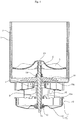
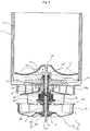
- FIG. 1 is a longitudinal cross-sectional view of a washing machine according to an embodiment of the present disclosure.
- FIG. 2 is an exploded view of principal parts of FIG. 1 .
- FIG. 3 is a partially cut-away view of portion "A" of FIG. 1 , in which FIG. 3 (a) illustrates a state where a clutch is in a raised position, and FIG. 3 (b) illustrates a state where a clutch is in a lowered position.
- the washing machine includes: an outer tub 1 which accommodates wash water; an inner tub 2 which is disposed in the outer tub 1 to accommodate laundry, and rotates around a vertical axis; a pulsator 3 which is disposed in the inner tub 2; and a motor 10 which provides torque.
- the outer tub 1 is disposed in a casing (not shown) which forms an external appearance of the washing machine.
- the outer tub 1 may be suspended in the casing by a support rod (not shown).
- the support rod may be provided at each of four corners of the casing, and may be connected to the outer tub 1 by a suspension (not shown) which absorbs vibration of each support rod.
- the motor 10 may rotate in forward/reverse directions, and the pulsator 3 and the inner tub 2 may rotate by the motor 10. It is desired that the motor 10 is a Brushless Direct Current electric motor (BLDC), but is not necessarily limited thereto.
- BLDC Brushless Direct Current electric motor
- the motor 10 is an outer rotor type motor having, at the center, a stator (not shown) around which induction coils are wound, and a rotor 11 which rotates around the stator.
- the rotor 11 includes a bottom part 13, and a ring-shaped side part 12 which is extended upwardly from the bottom part 13.
- a lower end portion of the inner shaft 4 may be connected by a rotor bush 14 to a rotor hub 15 which is fixed to the bottom part 13.
- Five magnets (not shown) are arranged on an inner circumferential surface of the side part 12 of the motor 10 along a circumferential direction, so as to rotate the rotor 11 by a magnetic field generated between the stator and the magnets.
- the inner shaft 4 is connected to the pulsator 3.
- the pulsator 3 has coupling holes formed at the center, and screws 23 pass through the coupling holes from top to bottom to be coupled to the inner shaft 4.
- the outer shaft 9 is connected to the inner tub 2, and has a tubular shape with a hollow 9h through which the inner shaft 4 passes.
- a hub base 18, which is connected to the bottom of the inner tub 2, may be provided at a lower part of the inner tub 2.
- An opening is formed at the center of the bottom of the inner tub 2; and a coupling member, such as a screw or a bolt, passes through portions of the hub base 18 which come into contact with the circumference of the opening, such that the hub base 18 may be coupled to the bottom of the inner tub 2.
- the hub base 18 rotates along with the outer shaft 9.
- the outer shaft 9 is engaged (or tooth-engaged) with the hub base 18.
- a tooth surface 9a (see FIG. 2 ), which forms a spline, may be formed on the outside of the outer shaft 9.
- the hub base 18 may be formed in a disc shape, and may have, at the center, a boss 18a through which the outer shaft 9 passes.
- a tooth groove, which is engaged with the tooth surface may be formed on an inner circumferential surface of the boss 18a. As a concavo-convex portion, such as tooth, key, and the like, is engaged with the tooth groove formed at the boss 18a, torque may be transferred to the hub base 18 during rotation of the outer shaft 9.
- the outer shaft 9 After passing through the boss 18a of the hub base 18, the outer shaft 9 may protrude upwards, and the protruding portion may be coupled to a nut 19. Further, a sealer 66, which performs sealing to prevent water contained in the inner tub 2 from penetrating into the hollow 9h, may be provided at the protruding portion.
- a bearing housing 16 may be disposed below the outer tub 1.
- the bearing housing 16 may be connected to a bottom surface of the outer tub 1.
- a bearing 16a, which supports the outer shaft 9, may be provided in the bearing housing 16.
- the inner shaft 4 rotates every time the motor 10 rotates.
- torque provided by the motor 10 should be transferred from the inner shaft 4 to the outer shaft 9, and the transfer of torque is performed by a raising and lowering motion of the clutch 6.
- the clutch 6 is disposed between the inner shaft 4 and the outer shaft 9.
- the clutch 6 may be raised and lowered while being engaged (or tooth-engaged) with the outer shaft 9; and may be screw-coupled to the inner shaft 4, to be raised and lowered by rotation of the inner shaft 4 between a raised position (see (a) of FIG. 3 ) and a lowered position (see (b) of FIG. 3 ).
- the clutch 6 may be made of a steel material.
- the outer circumferential surface of the clutch 6 is spline-coupled to the inner circumferential surface of the outer shaft 9 which defines the hollow 9h, so that the clutch 6 may be raised or lowered with respect to the outer shaft 9.
- a tooth surface, which forms a spline is formed on the outer circumferential surface of the clutch 6, and a tooth groove, which is engaged with the tooth surface, is formed on the inner circumferential surface of the outer shaft 9. It is desired that a cross section of the teeth, which form the spline, has a triangle shape, such that serrations, which are engaged with each other, may be formed on the outer circumferential surface of the clutch 6 and the inner circumferential surface of the outer shaft 9 respectively (serration coupling).
- the concavo-convex portion, such as tooth, key, and the like, which is formed on the tooth surface of the clutch 6, is engaged with the tooth groove formed on the inner circumferential surface of the outer shaft 9, such that in the case where the clutch 6 is no longer raised after reaching a raised position, or is no longer lowered after reaching a lowered position, torque is transferred to the outer shaft 9 through the clutch 6, which will be described in further detail later.
- a helix thread 41 is formed on the outer circumferential surface of the inner shaft 4 along an axial direction, and a thread (not shown), which is engaged with the thread 41, is formed on the inner circumferential surface of the clutch 6.
- the outer circumferential surface of the clutch 6 is spline-coupled to the inner circumferential surface of the outer shaft 9, and the inner shaft 4 and the clutch 6 are screw-coupled, such that when the inner shaft 4 rotates while a raising or lowering motion of the clutch 6 is not restricted, the clutch 6 is raised or lowered according to a rotational direction of the inner shaft 4 while rotating relative to the thread 41. In this case, only the pulsator 3 rotates while the inner tub 2 is in a stationary state.
- a rotational direction of the inner shaft 4, which induces the clutch 6 to be raised will be referred to as a forward direction, and a direction opposite to the forward direction will be referred to as a reverse direction.
- the clutch 6 As the inner shaft 4 rotates in the forward direction, the clutch 6 reaches a predetermined raised position (see (a) of FIG. 3 ) and is restrained from being raised further, When the inner shaft 4 continues to rotate in the forward direction while the clutch 6 is restricted from being raised, the outer shaft 9 also rotates in the forward direction.
- the clutch 6 reaches a predetermined lowered position (see (b) of FIG. 3 ) and is restrained from being lowered further.
- the outer shaft 9 also rotates in the reverse direction.
- At least one of the raised position and the lowered position of the clutch 6 may be restricted by the thread 41. That is, when the clutch 6 rotates relative to the inner shaft 4 in the reverse direction and reaches the top of the thread 41, the clutch 6 may no longer rotate, and thus its raising motion is restricted and the position of the clutch 6 at this point is determined to be a raised position.
- an upper stopper which restrains the clutch 6 from being raised, and/or a lower stopper which restrains the clutch 6 from being lowered, may also be included.
- the bearing 27 interposed between the inner shaft 4 and the outer shaft 9 may be the upper stopper.
- a bearing may be further included to be used as the lower stopper.
- the upper stopper may be a bush 75 fixed to the inner shaft 4. In this case, when the clutch 75 comes into contact with the bush 75 while being raised, the clutch 6 may no longer be raised. Further, according to an embodiment, the upper stopper may be a protrusion that is formed at the inner shaft 4 or the outer shaft 9 to restrict movement of the clutch 6. For example, the upper stopper or the lower stopper may be formed by putting a ring on the inner shaft 4 or by forming a protrusion at the outer circumferential surface of the inner shaft 4. However, the upper stopper and the lower stopper are not limited thereto, and may be provided in various known manners.
- the lower stopper may be a rotor bush 14 or a rotor hub 15. In this case, when the clutch 6 comes into contact with the rotor bush 14 or the rotor hub 15 while being lowered, the clutch 6 may no longer be lowered. Further, according to an embodiment, the lower stopper may be a protrusion that is formed at the inner shaft 4 or the outer shaft 9 to restrict movement of the clutch 6.
- the upper stopper and the lower stopper are not limited thereto, and may be provided in various known manners.
- a movement area of the clutch 6 inside the hollow 9h formed at the outer shaft 9 may be provided outside of the inner tub 2. Further, the movement area of the clutch 6 may be provided below the outer tub 1. The movement area of the clutch 6 (or a space for installing or operating the clutch 6) is not provided inside the inner tub 2, the pulsator 3 may be disposed on the bottom of the inner tub 2, as in the case of a general washing machine.
- FIG. 3 (a) illustrates a state where the clutch 6 reaches the raised position.
- the clutch 6 may no longer be raised, such that the outer shaft 8 rotates in the forward direction. This is the case where the pulsator 3 and the inner tub 2 rotates together in the forward direction.
- a maximum angle (or number of rotations), at which the pulsator 3 may continuously rotate while the inner tub 2 is in a stationary state may be determined according to a maximum angle (or number of rotations) at which the clutch 6 may continuously rotate between the lowered position and the raised position.
- the pulsator 3 may rotate in the forward direction or the reverse direction according to a rotational direction of the motor 10.
- the rotational direction of the pulsator 3 is determined according to the rotational direction of the inner shaft 4, such that by controlling the rotational direction of the motor 10, stirring rotation of the pulsator 3 may be induced.
- FIG. 3 (b) illustrates a state where the clutch 6 reaches the lowered position.
- the clutch 6 may no longer be lowered, such that the outer shaft 8 rotates in the reverse direction. This is the case where the pulsator 3 and the inner tub 2 rotates together in the reverse direction.
- FIG. 4 is a longitudinal cross-sectional view of a washing machine according to another embodiment of the present disclosure.
- the same parts as those described in the above embodiments are denoted by the same reference numerals, and these parts are described above, such that detailed description thereof will be omitted.
- the washing machine according to the embodiment of the present disclosure has parts which are substantially the same as those described in the above embodiments, except that the clutch 6 is installed at a different position. That is, the clutch 6 is disposed inside the hollow 9h formed at the outer shaft 9, and at least a portion of a movement area of the clutch 6 is provided inside the inner tub 2.
- the entire movement area of the clutch 6 is provided inside the inner tub 2, but is not limited thereto, and the clutch 6 may be configured to be lowered below the inner tub 2.
- the movement area of the clutch 6 may be provided below the pulsator 3.
- FIG. 5 is a longitudinal cross-sectional view of a washing machine according to yet another embodiment of the present disclosure.
- FIG. 6 is a diagram illustrating a portion of the washing machine of FIG. 5 .
- FIG. 7 is a cross-sectional view of FIG. 6 .
- the washing machine includes: an outer tub 1 which accommodates wash water; an inner tub 2 which is disposed in the outer tub 1 to accommodate laundry, and rotates around a vertical axis; a motor 10 which provides torque; an outer shaft 9 which has a hollow 9h and rotates the inner tub 2; an inner shaft 4 which rotates inside the hollow 9h by the motor 10; and a pulsator 3 which is disposed in the inner tub 2 and is connected to the inner shaft 4.
- an outer tub 1 which accommodates wash water
- an inner tub 2 which is disposed in the outer tub 1 to accommodate laundry, and rotates around a vertical axis
- a motor 10 which provides torque
- an outer shaft 9 which has a hollow 9h and rotates the inner tub 2
- an inner shaft 4 which rotates inside the hollow 9h by the motor 10
- a pulsator 3 which is disposed in the inner tub 2 and is connected to the inner shaft 4.
- the washing machine according to the embodiment of the present disclosure is different from the above-described embodiments in that: the washing machine according to the embodiment includes the clutch 160 which is screw-coupled to the inner shaft 4 inside the hollow 9h of the outer shaft 9, and an elevation guide 170 which rotates along with the inner tub 2 when the inner tub 2 rotates, and restricts rotation of the clutch 160 when the inner shaft 4 rotates, so as to elevate the clutch 160.
- the clutch 160 which is screw-coupled to the inner shaft 4 inside the hollow 9h of the outer shaft 9
- an elevation guide 170 which rotates along with the inner tub 2 when the inner tub 2 rotates, and restricts rotation of the clutch 160 when the inner shaft 4 rotates, so as to elevate the clutch 160.
- the elevation guide 170 may be fixed to a hub base 18.
- the elevation guide 170 includes: a coupling plate 171 which is coupled to a top surface of the hub base 18; and at least one guide bar 172 which is extended upwardly from the coupling plate 171 and is engaged with the clutch 160.
- the coupling plate 171 may be formed in a ring shape.
- the inner shaft 4 and the outer shaft 9 may pass through an open center portion of the coupling plate 171.
- the guide bar 172 may be extended upwardly from two points of the top surface of the coupling plate 171.
- the guide bar 172 may be disposed symmetrically.
- a rib 18c which is formed to surround the coupling plate 171, may protrude from the hub base 18.
- the rib 18c serves to fix the coupling plate 171 so that the coupling plate 171 may not be shaken, and a plurality of ribs 18c may be formed along the circumference of the coupling plate 171.
- the clutch 160 may be elevated along the guide bar 172.
- the clutch 160 is formed in a ring shape and is screw-coupled to the inner shaft 4, and an elevation guide groove 165, which is engaged with the guide bar 172, is formed on the outer circumferential surface of the guide bar 172. It is desired that two or more guide bars 172 are provided so that the clutch 160 may be elevated stably, and a plurality of elevation guide grooves 165 are engaged with each of the guide bars 172.
- the raising and lowering motion of the clutch 160 may be restricted in the same manner as the above-described embodiments. However, as the clutch 160 is disposed outside of the outer shaft 9, such that depending on embodiments, when the outer shaft 9 is extended above the inner shaft 4, the lower stopper may be the top of the outer shaft 9.
- the inner shaft 4 includes: a shank 42 having the thread 41 which is connected to the clutch 6; and a bolt head 43 formed on the top of the shank 42.
- the bolt head 43 may have a coupling hole coupled with a screw 23 (see FIG. 1 ) which has passed through the pulsator 3.
- the upper stopper may be the bolt head 43 of the inner shaft 4.
- the clutch 6 may no longer be raised, and the position of the clutch 6 at this point is determined to be a raised position.
- the upper stopper may also be applied to the washing machine according to another embodiment described above with reference to FIG. 4 .
- the principle of motions of the clutch 160 according to a rotational direction of the motor 10 is substantially the same as the above-described embodiments, except that the clutch 160 is guided by the guide bar 172 between the raised position and the lowered position, and the rotation of the clutch 160 is restricted by the guide bar 172 while the inner tub 2 is in a stationary state. Accordingly, detailed description thereof will be omitted.
- a water supply part e.g., water supply valve
- a drain part e.g., drain value or drain pump
- the level of water in the inner tub 2 may be raised by the supply of water from the water supply part, and may be lowered by the drainage by the drain part.
- a circulation spray device may be further included, which circulates water, supplied from the outer tub 1, through a predetermined circulation tube by using a circulation pump (not shown), and then sprays the water into the inner tub 2 through a nozzle (not shown).
- FIG. 8 is a longitudinal cross-sectional view of a washing machine according to still another embodiment of the present disclosure.
- FIG. 9 is an enlarged view of a portion of the washing machine illustrated in FIG. 8 , in which FIG. 9 (a) schematically illustrates an action of a planetary gear train when the pulsator rotates relative to the inner tub; and FIG. 9 (b) schematically illustrates an action of a planetary gear train when the inner tub and the pulsator rotates together.
- FIG. 10 (a) schematically illustrates an action of a planetary gear train when a pulsator rotates relative to an inner tub; and FIG. 10 (b) schematically illustrates an action of a planetary gear train when a pulsator and an inner tub rotate together.
- FIG. 9 schematically illustrates an action of a planetary gear train when the pulsator rotates relative to the inner tub
- FIG. 10 (b) schematically illustrates an action of a planetary gear train when a pulsator and an inner tub
- FIG. 11 is a partially cut-away view of portion "A" of FIG. 8 , in which FIG. 11 (a) illustrates a state where a clutch is in a lowered position, and FIG. 11 (b) illustrates a state where a clutch is in a raised position.
- the washing machine may further include a planetary gear train 8 which transfers torque of the motor 10 to rotate the inner shaft 4.
- the planetary gear train 8 may receive an input of torque of a drive shaft 10a, and converts the input torque according to a predetermined velocity ratio or a torque ratio, to rotate the inner shaft 4.
- a movement area of the clutch 6 inside a first hollow formed at the outer shaft 9 may be provided outside of the inner tub 2. Further, the movement area of the clutch 6 may be provided below the outer tub 1. The movement area of the clutch 6 (or a space for installing or operating the clutch 6) is not provided inside the inner tub 2, such that the pulsator 3 may be disposed on the bottom of the inner tub 2, as in the case of a general washing machine.
- the planetary gear train 8 may transfer the torque of the motor 10 to rotate the inner shaft 4.
- the planetary gear train 8 may convert the torque input from the drive shaft 10a according to a predetermined gear ratio, to rotate the inner shaft 4.
- the gear ratio may be determined according to the number of teeth of the sun gear 81, the pinion gear 82, and the ring gear 84.
- the planetary gear train 8 is disposed in a gear housing 5 which is connected (or shaft-coupled) to the outer shaft 9. As the gear housing 5 is shaft-coupled to the outer shaft 9, the gear housing 5 rotates along with the outer shaft 9 during rotation of the outer shaft 9.
- the gear housing 5 has a boss 533 which is formed on the top thereof.
- the outer shaft 9 has an upper portion 91, which has an engagement groove 9r formed on the inner circumferential surface thereof, and a lower portion 92 having an outer diameter larger than that of the upper portion 91. As the lower portion 92 is connected to the boss 533, the outer shaft 9 and the gear housing 5 are shaft-coupled to each other.
- the gear housing 5 includes a lower housing 52 and an upper housing 53.
- the lower housing 52 and the upper housing 53 are connected with each other by a coupling member such as a screw, a bolt, and the like.
- the lower housing 52 is formed in a tubular shape, having a second hollow which longitudinally extends in a vertical direction, and the drive shaft 10a is inserted in the second hollow.
- the lower housing 52 includes a hollow shaft 521 which forms the second hollow, and a lower flange 522 which extends outwardly from the top of the hollow shaft 521 along a radial direction.
- a bearing 33 is interposed between the hollow shaft 521 and the drive shaft 10a, to support the hollow shaft 521 and the drive shaft 10a in a manner that allows them to rotate relative to each other.
- the upper housing 53 is disposed above the lower housing 52.
- the upper housing 53 forms a predetermined accommodating space above the lower flange 522, and the planetary gear train 8 is disposed inside the accommodating space.
- the accommodating space extends vertically, having an open top and bottom.
- the upper housing 53 has the boss 533 which is connected to the outer shaft 9, and the top of the accommodating space is opened by the boss 533.
- the upper housing 53 includes: a housing main body 531 which forms an inner circumferential surface surrounding the ring gear 84; and the upper flange 532 which extends outwardly from the open bottom of the housing main body 531 along a radial direction, and is connected with the lower flange 522, in which the boss 533 extends upwardly from the housing main body 531.
- the planetary gear train 8 includes the sun gear 81, the pinion gear 82, the carrier 83, and the ring gear 84.
- the sun gear 81 is connected to the drive shaft 10a, to rotate integrally with the drive shaft 10a.
- the sun gear 81 is a helical gear
- the pinion gear 82 and the ring gear 84 may also have teeth of a helical gear shape to correspond to the sun gear 81, but are not limited thereto.
- the sun gear 81 may be a spur gear
- the pinion gear 82 and the ring gear 84 may have teeth of a spur gear shape.
- the ring gear 84 may be fixed inside the housing main body 531 (or fixed to the housing main body 531). That is, the ring gear 84 may be integrally formed with the gear housing 5.
- the ring gear 84 has teeth on the inner circumferential surface that defines a ring-shaped opening.
- the pinion gear 82 is interposed between the sun gear 81 and the ring gear 84, to be engaged with the sun gear 81 and the ring gear 84.
- a plurality of pinion gears 82 (1), 82 (2), 82 (3), and 82 (4) may be disposed along the circumference of the sun gear 81, and each of the pinion gears 82 may be rotatably supported by the carrier 83.
- the pinion gear 82 may be made of polyoxymethylene (POM) resin.
- the carrier 83 is connected (shaft-coupled) to the inner shaft 4.
- the carrier 83 is a type of a link that connects the pinion gear 82 and the inner shaft 4. That is, as the pinion gear 82 revolves around the sun gear 82, the carrier 83 rotates, and the inner shaft 4 rotates accordingly.
- the carrier 83 includes: an upper plate 831 having a boss 831a which is connected to the inner shaft 4; a lower plate 832 which is spaced apart downwardly from the upper plate 831, and has a through-hole which is formed at the center of the lower plate 832, and through which the drive shaft 10a passes; and a gear shaft 833 which connects the upper plate 831 and the lower plate 832.
- a plurality of gear shafts 833 may be provided along a circumferential direction, and the pinion gear 82 may be installed at each of the gear shafts 833.
- the gear shaft 833 may be installed to be rotatable with respect to the upper plate 831 and/or the lower plate 832, such that the pinion gear 82 and the gear shaft 833 may rotate together. Alternatively, rotation of the gear shaft 833 may be restricted, and the pinion gear 82 may rotate with respect to the gear shaft 833.
- the boss 831a formed at the upper plate 831 may be disposed in the boss 533 formed at the aforementioned upper housing 53, and the bearing 32 may be interposed between the boss 831a and the outer shaft 9.
- FIG. 11 illustrates a state where the clutch 6 reaches a raised position.
- the clutch 6 may no longer be raised, such that the outer shaft 8 rotates in the forward direction. This is the case where the pulsator 3 and the inner tub 2 rotate together in the forward direction.
- the clutch 6 is lowered.
- the outer shaft 9 When the drive shaft 10a rotates while the clutch 6 is between the raised position and the lowered position, the outer shaft 9 may be induced to rotate due to inertia or load on the inner tub 2. That is, when the load acting on the inner shaft 4 by the inner tub 2 is sufficiently large, the outer shaft 9 is maintained in a stationary state, and only the inner shaft 4 rotates; or when the load is not large enough to restrict the rotation of the outer shaft 9, the outer shaft 9 may rotate in an opposite direction to the inner shaft 4.
- FIG. 10 (a) illustrates an action of a planetary gear train in the case where the drive shaft 10a rotates in the reverse direction, and the clutch 6 is lowered. Assuming that rotation of the ring gear 84 is restricted, it can be seen that when the drive shaft 10a rotates at an angular speed of W1, the carrier 83 rotates at an angular speed of W3 in the same direction as the drive shaft 10a (W1>W3).
- a maximum angle (or number of rotations), at which the pulsator 3 may continuously rotate while the inner tub 2 is in a stationary state may be determined according to a maximum angle (or number of rotations) at which the clutch 6 may continuously rotate between the lowered position and the raised position.
- the pulsator 3 may rotate in the forward direction or the reverse direction according to a rotational direction of the motor 10.
- the rotational direction of the pulsator 3 is determined according to the rotational direction of the inner shaft 4, such that by controlling the rotational direction of the motor 10, stirring rotation of the pulsator 3 may be induced.
- FIG. 11 (a) illustrates a state where the clutch 6 reaches the lowered position.
- the clutch 6 may be no longer lowered, such that the outer shaft 8 rotates in the reverse direction. This is the case where the pulsator 3 and the inner tub 2 rotate together in the reverse direction.
- FIG. 10 (b) illustrates a case where the drive shaft 10a continuously rotates in the reverse direction while the clutch 6 reaches the lowered position, i.e., a case where the pulsator 3 and the inner tub 2 rotates together; and it can be seen that the both the carrier 83 and the ring gear 84 rotate integrally with the drive shaft 10a (i.e., at the same angular speed) in the same direction as the drive shaft 10a.
- the washing machine of the present disclosure has an effect in that a clutch system, which connects or disconnects a wash shaft (or inner shaft) and a dehydration shaft (or outer shaft), may be simplified compared to a general clutch system.
- the clutch system of the present disclosure operates by a motor which provides power for rotating a pulsator, such that a separate power source or a driving source for operating the clutch is not required.
- wash shaft and the dehydration shaft are connected or disconnected by controlling a rotational direction of the motor, such that the clutch system of the present disclosure may be controlled in a very simple manner.
- a clutch system which connects or disconnects an inner shaft and an outer shaft, may be simplified compared to a general clutch system.
- the clutch system of the present disclosure operates by a motor which provides power for rotating the inner shaft, such that a separate power source or a driving source for operating the clutch is not required.
- the inner shaft and the outer shaft are connected or disconnected by controlling a rotational direction of the motor, such that the clutch system of the present disclosure may be controlled in a very simple manner.
- a screw coupling between the inner shaft and the clutch or a spline coupling between the clutch and the outer shaft is a very firm shaft-coupling, such that even when the inner shaft is rotated by strong torque, components are not damaged during power transfer. Accordingly, even when using a planetary gear train which outputs torque after increasing torque by adjusting a gear ratio, operations may be performed stably under a high load without damage of components.
Landscapes
- Engineering & Computer Science (AREA)
- General Engineering & Computer Science (AREA)
- Mechanical Engineering (AREA)
- Textile Engineering (AREA)
- Main Body Construction Of Washing Machines And Laundry Dryers (AREA)
Claims (17)
- Waschmaschine, die aufweist:einen Außenbottich (1) zum Aufnehmen von Waschwasser;einen Innenbottich (2), der im Außenbottich (1) angeordnet ist, um Wäsche aufzunehmen, und um eine senkrechte Achse drehbar ist;einen Motor (10), der Drehmoment bereitstellt;eine Außenwelle (9), die einen ersten Hohlraum (9h) hat, mit dem Innenbottich (2) verbunden ist, um den Innenbottich (2) zu drehen, und eine Zahnnut auf einer Innenumfangsfläche davon hat;eine Innenwelle (4), die mit dem Motor (10) verbunden ist und durch ihn im ersten Hohlraum (9h) gedreht wird und ein Spiralgewinde (41) hat, das auf einer Außenumfangsfläche davon in Axialrichtung gebildet ist;einen Pulsator (3), der im Innenbottich (2) angeordnet und mit der Innenwelle (4) verbunden ist; undeine Kupplung (6), die ein Gewinde auf einer Innenumfangsfläche davon hat, wobei das Gewinde mit dem Spiralgewinde der Innenwelle (4) im ersten Hohlraum (9h) der Außenwelle (9) verschraubt ist und eine Zahnfläche hat, die eine Verzahnung auf einer Außenfläche davon bildet, wobei die Zahnfläche mit der Zahnnut der Außenfläche (9) verzahnt ist,wobei bei Drehung der Innenwelle (4) in Vorwärtsrichtung und Erreichen einer vorbestimmten angehobenen Position durch die Kupplung (6) die Kupplung (6) daran gehindert ist, weiter angehoben zu werden, und die Außenwelle (9) in Vorwärtsrichtung dreht, und bei Drehung der Innenwelle (4) in Rückwärtsrichtung und bei Erreichen einer vorbestimmten abgesenkten Richtung durch die Kupplung (6) die Kupplung (6) daran gehindert ist, weiter abgesenkt zu werden, und die Außenwelle (9) in Rückwärtsrichtung dreht.
- Waschmaschine nach Anspruch 1, wobei ein Bewegungsbereich der Kupplung (6) innerhalb des ersten Hohlraums (9h) außerhalb des Innenbottichs (4) vorgesehen ist.
- Waschmaschine nach Anspruch 2, wobei der Bewegungsbereich der Kupplung (6) innerhalb des ersten Hohlraums (9h) unter dem Außenbottich (1) vorgesehen ist.
- Waschmaschine nach Anspruch 1, wobei mindestens ein Abschnitt eines Bewegungsbereichs der Kupplung (6) innerhalb des ersten Hohlraums (9h) innerhalb des Innenbottichs (2) vorgesehen ist.
- Waschmaschine nach Anspruch 4, wobei der Bewegungsbereich der Kupplung (6) innerhalb des ersten Hohlraums (9h) unter dem Pulsator (3) vorgesehen ist.
- Waschmaschine nach Anspruch 1, wobei die angehobene Position und/oder die abgesenkte Position an der Innenwelle (4) so gebildet sind, dass sie durch das Gewinde (41) beschränkt sind, das mit der Kupplung (6) verschraubt ist, wobei die angehobene Position ein Kopf des Gewindes (41) ist oder die abgesenkte Position ein Grund des Gewindes ist.
- Waschmaschine nach Anspruch 1, ferner mit einem oberen Anschlag, der an der Innenwelle (4) befestigt ist und die Kupplung (6) daran hindert, über die angehobene Position hinaus angehoben zu werden.
- Waschmaschine nach einem der Ansprüche 1 bis 7, ferner mit einem Planetengetriebe (8), das Drehmoment des Motors (10) überträgt, um die Innenwelle (4) zu drehen.
- Waschmaschine nach Anspruch 8, ferner mit einem Getriebegehäuse (5), das das Planetengetriebe (8) aufnimmt und mit der Außenwelle (9) wellengekoppelt ist, wobei das Planetengetriebe (8) aufweist:ein Hohlrad (84), das an einer Innenumfangsfläche des Getriebegehäuses (5) befestigt ist;ein Sonnenrad (81), das mit einer Antriebswelle (10a) des Motors (10) verbunden ist;ein Planetenrad (82), das zwischen dem Sonnenrad (81) und dem Hohlrad (84) eingefügt ist, um mit dem Sonnenrad (81) und dem Hohlrad (84) im Eingriff zu stehen; undeinen Träger (83), der mehrere Planetenräder (82(1), ..., 82(4)) drehbar stützt, um zu drehen, wenn die mehreren Planetenräder (82) um das Hohlrad (84) umlaufen, und der mit der Innenwelle (4) verbunden ist, um die Innenwelle (4) durch die Drehung zu drehen.
- Waschmaschine nach Anspruch 9, wobei das Getriebegehäuse (5) aufweist:ein unteres Gehäuse (82), das unter dem Planetengetriebe (8) angeordnet ist und einen zweiten Hohlraum hat, den die Antriebswelle (10a) durchläuft; undein oberes Gehäuse (53), das über dem unteren Gehäuse (82) angeordnet und mit dem unteren Gehäuse (82) verbunden ist, so dass ein Raum zum Aufnehmen des Planetengetriebes (8) dazwischen gebildet ist, und mit einem unteren Endabschnitt der Außenwelle (9) wellengekoppelt ist.
- Waschmaschine nach Anspruch 9, wobei der Träger (83) einen Ansatz (831a) aufweist, der mit der Innenwelle (4) wellengekoppelt ist,
wobei der Träger (83) ferner ein Lager (32) aufweist, das zwischen dem Ansatz (831a) und der Außenwelle (9) eingefügt ist. - Waschmaschine nach Anspruch 11, wobei die abgesenkte Position durch Kontakt zwischen der Kupplung (6) und dem Ansatz (831a) festgelegt ist.
- Waschmaschine nach Anspruch 8, wobei ein Bewegungsbereich der Kupplung (6) innerhalb des ersten Hohlraums (9h) außerhalb des Innenbottichs (2) vorgesehen ist.
- Waschmaschine, die aufweist:einen Außenbottich (1) zum Aufnehmen von Waschwasser;einen Innenbottich (2), der im Außenbottich (1) angeordnet ist, um Wäsche aufzunehmen, und um eine senkrechte Achse drehbar ist;einen Motor (10), der Drehmoment bereitstellt;eine Außenwelle (9), die einen Hohlraum (9h) hat und mit dem Innenbottich (2) verbunden ist, um den Innenbottich (2) zu drehen;eine Innenwelle (4), die mit dem Motor (10) verbunden ist und durch ihn gedreht wird und ein Spiralgewinde hat, das auf einer Außenumfangsfläche davon in Axialrichtung gebildet ist;einen Pulsator (3), der im Innenbottich (2) angeordnet und mit der Innenwelle (4) verbunden ist;eine Kupplung (160), die ein Gewinde auf einer Innenumfangsfläche davon hat, wobei das Gewinde mit dem Spiralgewinde der Innenwelle (4) im Hohlraum (9h) der Außenwelle (9) verschraubt ist und eine Höhenführungsnut (165) hat, die auf einer Außenumfangsfläche davon gebildet ist; undeine Höhenführung (170), die zusammen mit dem Innenbottich (2) dreht, wenn der Innenbottich (2) dreht, und eine Führungsstange (172) aufweist, die mit der Höhenführungsnut (165) im Eingriff steht und Drehung der Kupplung (160) verhindert, wenn die Innenwelle (4) dreht, um die Kupplung (160) zu heben,wobei bei Drehung der Innenwelle (4) in Vorwärtsrichtung und Erreichen einer vorbestimmten angehobenen Position durch die Kupplung (160) die Kupplung (160) daran gehindert ist, weiter angehoben zu werden, und die Außenwelle (9) in Vorwärtsrichtung dreht, und bei Drehung der Innenwelle (4) in Rückwärtsrichtung und bei Erreichen einer vorbestimmten abgesenkten Richtung durch die Kupplung (160) die Kupplung (160) daran gehindert ist, weiter abgesenkt zu werden, und die Außenwelle (9) in Rückwärtsrichtung dreht.
- Waschmaschine nach Anspruch 14, wobei die angehobene Position und die abgesenkte Position an der Innenwelle (4) so gebildet sind, dass sie durch das Gewinde (41) beschränkt sind, das mit der Kupplung (160) verschraubt ist.
- Waschmaschine nach Anspruch 14 oder 15, die ferner aufweist:einen oberen Anschlag, der die Kupplung (160) daran hindert, über die angehobene Position hinaus angehoben zu werden; undeinen unteren Anschlag, der die Kupplung (160) daran hindert, über die abgesenkte Position hinaus abgesenkt zu werden.
- Waschmaschine nach Anspruch 14, 15 oder 16, ferner mit einer Nabenbasis (18), die mit einem Boden des Innenbottichs (2) verbunden ist und in einem Stück mit der Außenwelle (9) dreht,
wobei die Höhenführung (170) aufweist:eine Koppelplatte (171), die mit einer Kopffläche der Nabenbasis (18) gekoppelt ist; unddie Führungsstange (172), die sich von der Koppelplatte (171) nach oben erstreckt und im Eingriff mit der Kupplung (160) steht,wobei die Kupplung (160) entlang der Führungsstange (172) angehoben wird.
Applications Claiming Priority (2)
| Application Number | Priority Date | Filing Date | Title |
|---|---|---|---|
| KR20170153826 | 2017-11-17 | ||
| KR20180022108 | 2018-02-23 |
Publications (2)
| Publication Number | Publication Date |
|---|---|
| EP3486359A1 EP3486359A1 (de) | 2019-05-22 |
| EP3486359B1 true EP3486359B1 (de) | 2021-06-02 |
Family
ID=64331921
Family Applications (1)
| Application Number | Title | Priority Date | Filing Date |
|---|---|---|---|
| EP18206740.5A Active EP3486359B1 (de) | 2017-11-17 | 2018-11-16 | Waschmaschine |
Country Status (3)
| Country | Link |
|---|---|
| US (2) | US10865508B2 (de) |
| EP (1) | EP3486359B1 (de) |
| CN (2) | CN109797522B (de) |
Family Cites Families (19)
| Publication number | Priority date | Publication date | Assignee | Title |
|---|---|---|---|---|
| JPH1133278A (ja) * | 1997-07-18 | 1999-02-09 | Toshiba Corp | 洗濯機 |
| KR100359340B1 (ko) * | 1998-07-01 | 2003-01-24 | 삼성전자 주식회사 | 세탁기의동력전달장치 |
| TW503288B (en) | 1999-03-26 | 2002-09-21 | Toshiba Corp | Washing machine serving also for dehydration |
| CN2649624Y (zh) * | 2001-11-08 | 2004-10-20 | 海尔集团公司 | 双向驱动洗涤式洗衣机 |
| KR100615569B1 (ko) * | 2003-02-06 | 2006-08-25 | 엘지전자 주식회사 | 전자동 세탁기 및 그 구동장치 |
| DE602004031407D1 (de) | 2003-02-06 | 2011-03-31 | Lg Electronics Inc | Waschmaschine |
| CN1536122A (zh) * | 2003-04-11 | 2004-10-13 | 乐金电子(天津)电器有限公司 | 全自动洗衣机及其控制方法 |
| CN1566475A (zh) * | 2003-06-17 | 2005-01-19 | 乐金电子(天津)电器有限公司 | 全自动洗衣机的联轴器啮合结构 |
| KR100688187B1 (ko) * | 2004-10-13 | 2007-03-02 | 엘지전자 주식회사 | 세탁기의 클러치 장치 |
| CN2793129Y (zh) * | 2005-04-12 | 2006-07-05 | 肇庆华尔车辆检测设备有限公司 | 一种旋转升降洗衣机内桶的传动装置 |
| JP2007319578A (ja) * | 2006-06-05 | 2007-12-13 | Matsushita Electric Ind Co Ltd | 洗濯機 |
| KR101466334B1 (ko) * | 2008-02-25 | 2014-12-10 | 삼성전자 주식회사 | 세탁기 |
| CN104884699B (zh) * | 2012-12-18 | 2017-02-15 | 阿莫泰克有限公司 | 洗衣机的驱动装置及具有该驱动装置的洗衣机 |
| CN105358756B (zh) * | 2013-07-19 | 2017-12-05 | 阿莫泰克有限公司 | 洗衣机驱动装置及具有其的洗衣机 |
| CN104372561B (zh) * | 2013-08-15 | 2018-08-07 | 青岛海尔洗衣机有限公司 | 一种变频手搓式电机减速离合装置及洗衣机 |
| KR101612405B1 (ko) * | 2014-06-30 | 2016-04-15 | 주식회사 아모텍 | 세탁기 및 세탁기 구동방법 |
| KR101751118B1 (ko) * | 2015-08-27 | 2017-06-29 | 주식회사 지앤제이 | 세탁기용 스테이터 |
| KR20170087676A (ko) * | 2016-01-21 | 2017-07-31 | 엘지전자 주식회사 | 의류처리장치 |
| US10240272B2 (en) * | 2016-05-13 | 2019-03-26 | Whirlpool Corporation | Laundry treating appliance with drive attachment mechanism |
-
2018
- 2018-11-16 EP EP18206740.5A patent/EP3486359B1/de active Active
- 2018-11-19 CN CN201811376427.6A patent/CN109797522B/zh active Active
- 2018-11-19 CN CN202110491141.8A patent/CN113026303B/zh not_active Expired - Fee Related
- 2018-11-19 US US16/195,013 patent/US10865508B2/en active Active
- 2018-11-19 US US16/195,494 patent/US10865509B2/en active Active
Non-Patent Citations (1)
| Title |
|---|
| None * |
Also Published As
| Publication number | Publication date |
|---|---|
| US20190153646A1 (en) | 2019-05-23 |
| CN113026303A (zh) | 2021-06-25 |
| US10865509B2 (en) | 2020-12-15 |
| US20190153645A1 (en) | 2019-05-23 |
| CN109797522B (zh) | 2021-05-25 |
| CN109797522A (zh) | 2019-05-24 |
| CN113026303B (zh) | 2022-12-16 |
| US10865508B2 (en) | 2020-12-15 |
| EP3486359A1 (de) | 2019-05-22 |
Similar Documents
| Publication | Publication Date | Title |
|---|---|---|
| US7614262B2 (en) | Multiple directional clutch for washing machine | |
| US10793990B2 (en) | Method for controlling washing machine | |
| KR102163318B1 (ko) | 세탁기 | |
| US5873269A (en) | Power system of washing machine | |
| US11746459B2 (en) | Washing machine | |
| KR20200131120A (ko) | 세탁기의 구동장치 | |
| EP3486359A1 (de) | Waschmaschine | |
| KR102521864B1 (ko) | 세탁기 | |
| US11124912B2 (en) | Planetary helical gear train for a transmission assembly of a washing machine appliance | |
| KR20190121732A (ko) | 세탁기의 제어방법 | |
| KR100442250B1 (ko) | 세탁기 | |
| KR102101731B1 (ko) | 세탁기 | |
| KR102300789B1 (ko) | 세탁기 | |
| KR20200001010A (ko) | 세탁기 | |
| KR20190050221A (ko) | 세탁기 | |
| KR102364625B1 (ko) | 세탁기 | |
| KR102036225B1 (ko) | 세탁기 | |
| KR102045005B1 (ko) | 세탁기 | |
| KR20190050220A (ko) | 세탁기 | |
| KR101729525B1 (ko) | 탑로딩 세탁기 |
Legal Events
| Date | Code | Title | Description |
|---|---|---|---|
| PUAI | Public reference made under article 153(3) epc to a published international application that has entered the european phase |
Free format text: ORIGINAL CODE: 0009012 |
|
| STAA | Information on the status of an ep patent application or granted ep patent |
Free format text: STATUS: REQUEST FOR EXAMINATION WAS MADE |
|
| 17P | Request for examination filed |
Effective date: 20181217 |
|
| AK | Designated contracting states |
Kind code of ref document: A1 Designated state(s): AL AT BE BG CH CY CZ DE DK EE ES FI FR GB GR HR HU IE IS IT LI LT LU LV MC MK MT NL NO PL PT RO RS SE SI SK SM TR |
|
| AX | Request for extension of the european patent |
Extension state: BA ME |
|
| RBV | Designated contracting states (corrected) |
Designated state(s): AL AT BE BG CH CY CZ DE DK EE ES FI FR GB GR HR HU IE IS IT LI LT LU LV MC MK MT NL NO PL PT RO RS SE SI SK SM TR |
|
| GRAP | Despatch of communication of intention to grant a patent |
Free format text: ORIGINAL CODE: EPIDOSNIGR1 |
|
| STAA | Information on the status of an ep patent application or granted ep patent |
Free format text: STATUS: GRANT OF PATENT IS INTENDED |
|
| INTG | Intention to grant announced |
Effective date: 20210126 |
|
| GRAS | Grant fee paid |
Free format text: ORIGINAL CODE: EPIDOSNIGR3 |
|
| GRAA | (expected) grant |
Free format text: ORIGINAL CODE: 0009210 |
|
| STAA | Information on the status of an ep patent application or granted ep patent |
Free format text: STATUS: THE PATENT HAS BEEN GRANTED |
|
| REG | Reference to a national code |
Ref country code: CH Ref legal event code: EP |
|
| AK | Designated contracting states |
Kind code of ref document: B1 Designated state(s): AL AT BE BG CH CY CZ DE DK EE ES FI FR GB GR HR HU IE IS IT LI LT LU LV MC MK MT NL NO PL PT RO RS SE SI SK SM TR |
|
| REG | Reference to a national code |
Ref country code: GB Ref legal event code: FG4D |
|
| REG | Reference to a national code |
Ref country code: AT Ref legal event code: REF Ref document number: 1398520 Country of ref document: AT Kind code of ref document: T Effective date: 20210615 |
|
| REG | Reference to a national code |
Ref country code: IE Ref legal event code: FG4D |
|
| REG | Reference to a national code |
Ref country code: DE Ref legal event code: R096 Ref document number: 602018017954 Country of ref document: DE |
|
| REG | Reference to a national code |
Ref country code: LT Ref legal event code: MG9D |
|
| PG25 | Lapsed in a contracting state [announced via postgrant information from national office to epo] |
Ref country code: BG Free format text: LAPSE BECAUSE OF FAILURE TO SUBMIT A TRANSLATION OF THE DESCRIPTION OR TO PAY THE FEE WITHIN THE PRESCRIBED TIME-LIMIT Effective date: 20210902 Ref country code: FI Free format text: LAPSE BECAUSE OF FAILURE TO SUBMIT A TRANSLATION OF THE DESCRIPTION OR TO PAY THE FEE WITHIN THE PRESCRIBED TIME-LIMIT Effective date: 20210602 Ref country code: HR Free format text: LAPSE BECAUSE OF FAILURE TO SUBMIT A TRANSLATION OF THE DESCRIPTION OR TO PAY THE FEE WITHIN THE PRESCRIBED TIME-LIMIT Effective date: 20210602 Ref country code: LT Free format text: LAPSE BECAUSE OF FAILURE TO SUBMIT A TRANSLATION OF THE DESCRIPTION OR TO PAY THE FEE WITHIN THE PRESCRIBED TIME-LIMIT Effective date: 20210602 |
|
| REG | Reference to a national code |
Ref country code: NL Ref legal event code: MP Effective date: 20210602 |
|
| REG | Reference to a national code |
Ref country code: AT Ref legal event code: MK05 Ref document number: 1398520 Country of ref document: AT Kind code of ref document: T Effective date: 20210602 |
|
| PG25 | Lapsed in a contracting state [announced via postgrant information from national office to epo] |
Ref country code: GR Free format text: LAPSE BECAUSE OF FAILURE TO SUBMIT A TRANSLATION OF THE DESCRIPTION OR TO PAY THE FEE WITHIN THE PRESCRIBED TIME-LIMIT Effective date: 20210903 Ref country code: LV Free format text: LAPSE BECAUSE OF FAILURE TO SUBMIT A TRANSLATION OF THE DESCRIPTION OR TO PAY THE FEE WITHIN THE PRESCRIBED TIME-LIMIT Effective date: 20210602 Ref country code: PL Free format text: LAPSE BECAUSE OF FAILURE TO SUBMIT A TRANSLATION OF THE DESCRIPTION OR TO PAY THE FEE WITHIN THE PRESCRIBED TIME-LIMIT Effective date: 20210602 Ref country code: NO Free format text: LAPSE BECAUSE OF FAILURE TO SUBMIT A TRANSLATION OF THE DESCRIPTION OR TO PAY THE FEE WITHIN THE PRESCRIBED TIME-LIMIT Effective date: 20210902 Ref country code: RS Free format text: LAPSE BECAUSE OF FAILURE TO SUBMIT A TRANSLATION OF THE DESCRIPTION OR TO PAY THE FEE WITHIN THE PRESCRIBED TIME-LIMIT Effective date: 20210602 Ref country code: SE Free format text: LAPSE BECAUSE OF FAILURE TO SUBMIT A TRANSLATION OF THE DESCRIPTION OR TO PAY THE FEE WITHIN THE PRESCRIBED TIME-LIMIT Effective date: 20210602 |
|
| PG25 | Lapsed in a contracting state [announced via postgrant information from national office to epo] |
Ref country code: SM Free format text: LAPSE BECAUSE OF FAILURE TO SUBMIT A TRANSLATION OF THE DESCRIPTION OR TO PAY THE FEE WITHIN THE PRESCRIBED TIME-LIMIT Effective date: 20210602 Ref country code: SK Free format text: LAPSE BECAUSE OF FAILURE TO SUBMIT A TRANSLATION OF THE DESCRIPTION OR TO PAY THE FEE WITHIN THE PRESCRIBED TIME-LIMIT Effective date: 20210602 Ref country code: EE Free format text: LAPSE BECAUSE OF FAILURE TO SUBMIT A TRANSLATION OF THE DESCRIPTION OR TO PAY THE FEE WITHIN THE PRESCRIBED TIME-LIMIT Effective date: 20210602 Ref country code: ES Free format text: LAPSE BECAUSE OF FAILURE TO SUBMIT A TRANSLATION OF THE DESCRIPTION OR TO PAY THE FEE WITHIN THE PRESCRIBED TIME-LIMIT Effective date: 20210602 Ref country code: PT Free format text: LAPSE BECAUSE OF FAILURE TO SUBMIT A TRANSLATION OF THE DESCRIPTION OR TO PAY THE FEE WITHIN THE PRESCRIBED TIME-LIMIT Effective date: 20211004 Ref country code: NL Free format text: LAPSE BECAUSE OF FAILURE TO SUBMIT A TRANSLATION OF THE DESCRIPTION OR TO PAY THE FEE WITHIN THE PRESCRIBED TIME-LIMIT Effective date: 20210602 Ref country code: RO Free format text: LAPSE BECAUSE OF FAILURE TO SUBMIT A TRANSLATION OF THE DESCRIPTION OR TO PAY THE FEE WITHIN THE PRESCRIBED TIME-LIMIT Effective date: 20210602 Ref country code: CZ Free format text: LAPSE BECAUSE OF FAILURE TO SUBMIT A TRANSLATION OF THE DESCRIPTION OR TO PAY THE FEE WITHIN THE PRESCRIBED TIME-LIMIT Effective date: 20210602 Ref country code: AT Free format text: LAPSE BECAUSE OF FAILURE TO SUBMIT A TRANSLATION OF THE DESCRIPTION OR TO PAY THE FEE WITHIN THE PRESCRIBED TIME-LIMIT Effective date: 20210602 |
|
| REG | Reference to a national code |
Ref country code: DE Ref legal event code: R097 Ref document number: 602018017954 Country of ref document: DE |
|
| PLBE | No opposition filed within time limit |
Free format text: ORIGINAL CODE: 0009261 |
|
| STAA | Information on the status of an ep patent application or granted ep patent |
Free format text: STATUS: NO OPPOSITION FILED WITHIN TIME LIMIT |
|
| PG25 | Lapsed in a contracting state [announced via postgrant information from national office to epo] |
Ref country code: DK Free format text: LAPSE BECAUSE OF FAILURE TO SUBMIT A TRANSLATION OF THE DESCRIPTION OR TO PAY THE FEE WITHIN THE PRESCRIBED TIME-LIMIT Effective date: 20210602 |
|
| 26N | No opposition filed |
Effective date: 20220303 |
|
| PG25 | Lapsed in a contracting state [announced via postgrant information from national office to epo] |
Ref country code: AL Free format text: LAPSE BECAUSE OF FAILURE TO SUBMIT A TRANSLATION OF THE DESCRIPTION OR TO PAY THE FEE WITHIN THE PRESCRIBED TIME-LIMIT Effective date: 20210602 |
|
| PG25 | Lapsed in a contracting state [announced via postgrant information from national office to epo] |
Ref country code: MC Free format text: LAPSE BECAUSE OF FAILURE TO SUBMIT A TRANSLATION OF THE DESCRIPTION OR TO PAY THE FEE WITHIN THE PRESCRIBED TIME-LIMIT Effective date: 20210602 |
|
| REG | Reference to a national code |
Ref country code: CH Ref legal event code: PL |
|
| PG25 | Lapsed in a contracting state [announced via postgrant information from national office to epo] |
Ref country code: LU Free format text: LAPSE BECAUSE OF NON-PAYMENT OF DUE FEES Effective date: 20211116 Ref country code: IT Free format text: LAPSE BECAUSE OF FAILURE TO SUBMIT A TRANSLATION OF THE DESCRIPTION OR TO PAY THE FEE WITHIN THE PRESCRIBED TIME-LIMIT Effective date: 20210602 Ref country code: BE Free format text: LAPSE BECAUSE OF NON-PAYMENT OF DUE FEES Effective date: 20211130 |
|
| REG | Reference to a national code |
Ref country code: BE Ref legal event code: MM Effective date: 20211130 |
|
| PG25 | Lapsed in a contracting state [announced via postgrant information from national office to epo] |
Ref country code: LI Free format text: LAPSE BECAUSE OF NON-PAYMENT OF DUE FEES Effective date: 20211130 Ref country code: CH Free format text: LAPSE BECAUSE OF NON-PAYMENT OF DUE FEES Effective date: 20211130 |
|
| PG25 | Lapsed in a contracting state [announced via postgrant information from national office to epo] |
Ref country code: IE Free format text: LAPSE BECAUSE OF NON-PAYMENT OF DUE FEES Effective date: 20211116 |
|
| PG25 | Lapsed in a contracting state [announced via postgrant information from national office to epo] |
Ref country code: FR Free format text: LAPSE BECAUSE OF NON-PAYMENT OF DUE FEES Effective date: 20211130 |
|
| PG25 | Lapsed in a contracting state [announced via postgrant information from national office to epo] |
Ref country code: CY Free format text: LAPSE BECAUSE OF FAILURE TO SUBMIT A TRANSLATION OF THE DESCRIPTION OR TO PAY THE FEE WITHIN THE PRESCRIBED TIME-LIMIT Effective date: 20210602 |
|
| GBPC | Gb: european patent ceased through non-payment of renewal fee |
Effective date: 20221116 |
|
| PG25 | Lapsed in a contracting state [announced via postgrant information from national office to epo] |
Ref country code: HU Free format text: LAPSE BECAUSE OF FAILURE TO SUBMIT A TRANSLATION OF THE DESCRIPTION OR TO PAY THE FEE WITHIN THE PRESCRIBED TIME-LIMIT; INVALID AB INITIO Effective date: 20181116 |
|
| PG25 | Lapsed in a contracting state [announced via postgrant information from national office to epo] |
Ref country code: GB Free format text: LAPSE BECAUSE OF NON-PAYMENT OF DUE FEES Effective date: 20221116 |
|
| PG25 | Lapsed in a contracting state [announced via postgrant information from national office to epo] |
Ref country code: MK Free format text: LAPSE BECAUSE OF FAILURE TO SUBMIT A TRANSLATION OF THE DESCRIPTION OR TO PAY THE FEE WITHIN THE PRESCRIBED TIME-LIMIT Effective date: 20210602 |
|
| PG25 | Lapsed in a contracting state [announced via postgrant information from national office to epo] |
Ref country code: TR Free format text: LAPSE BECAUSE OF FAILURE TO SUBMIT A TRANSLATION OF THE DESCRIPTION OR TO PAY THE FEE WITHIN THE PRESCRIBED TIME-LIMIT Effective date: 20210602 |
|
| PG25 | Lapsed in a contracting state [announced via postgrant information from national office to epo] |
Ref country code: MT Free format text: LAPSE BECAUSE OF FAILURE TO SUBMIT A TRANSLATION OF THE DESCRIPTION OR TO PAY THE FEE WITHIN THE PRESCRIBED TIME-LIMIT Effective date: 20210602 |
|
| PGFP | Annual fee paid to national office [announced via postgrant information from national office to epo] |
Ref country code: DE Payment date: 20251002 Year of fee payment: 8 |