EP3485587B1 - Versorgungsnetzkommunikation mit glasfasern - Google Patents
Versorgungsnetzkommunikation mit glasfasern Download PDFInfo
- Publication number
- EP3485587B1 EP3485587B1 EP16742206.2A EP16742206A EP3485587B1 EP 3485587 B1 EP3485587 B1 EP 3485587B1 EP 16742206 A EP16742206 A EP 16742206A EP 3485587 B1 EP3485587 B1 EP 3485587B1
- Authority
- EP
- European Patent Office
- Prior art keywords
- signal
- control
- amplitude
- protection
- transmitter
- Prior art date
- Legal status (The legal status is an assumption and is not a legal conclusion. Google has not performed a legal analysis and makes no representation as to the accuracy of the status listed.)
- Active
Links
Images


Classifications
-
- H—ELECTRICITY
- H04—ELECTRIC COMMUNICATION TECHNIQUE
- H04B—TRANSMISSION
- H04B10/00—Transmission systems employing electromagnetic waves other than radio-waves, e.g. infrared, visible or ultraviolet light, or employing corpuscular radiation, e.g. quantum communication
- H04B10/07—Arrangements for monitoring or testing transmission systems; Arrangements for fault measurement of transmission systems
- H04B10/075—Arrangements for monitoring or testing transmission systems; Arrangements for fault measurement of transmission systems using an in-service signal
- H04B10/077—Arrangements for monitoring or testing transmission systems; Arrangements for fault measurement of transmission systems using an in-service signal using a supervisory or additional signal
- H04B10/0779—Monitoring line transmitter or line receiver equipment
-
- H—ELECTRICITY
- H04—ELECTRIC COMMUNICATION TECHNIQUE
- H04B—TRANSMISSION
- H04B10/00—Transmission systems employing electromagnetic waves other than radio-waves, e.g. infrared, visible or ultraviolet light, or employing corpuscular radiation, e.g. quantum communication
- H04B10/25—Arrangements specific to fibre transmission
-
- H—ELECTRICITY
- H04—ELECTRIC COMMUNICATION TECHNIQUE
- H04B—TRANSMISSION
- H04B10/00—Transmission systems employing electromagnetic waves other than radio-waves, e.g. infrared, visible or ultraviolet light, or employing corpuscular radiation, e.g. quantum communication
- H04B10/50—Transmitters
- H04B10/564—Power control
-
- H—ELECTRICITY
- H04—ELECTRIC COMMUNICATION TECHNIQUE
- H04B—TRANSMISSION
- H04B2210/00—Indexing scheme relating to optical transmission systems
- H04B2210/07—Monitoring an optical transmission system using a supervisory signal
- H04B2210/074—Monitoring an optical transmission system using a supervisory signal using a superposed, over-modulated signal
Definitions
- Embodiments presented herein relate to utility communications, and particularly to a method, a transmitter, a computer program, and a computer program product for utility communications.
- the communications network carries many of the vital signals that must be instantly exchanged, i.e., in real time, between different locations in the power systems to ensure the optimum control and protection of the power system.
- communications networks enable power utilities keep electricity flowing, all the way from generators to the consumers.
- Communications network conveys information for the remote control of unmanned stations, the transfer of data and load values from locations across the power grid to control centers, and transmits centralized or distributed control commands to the various sites. Communications relating to remote control of unmanned stations and transfer of data and load values is referred to as utility communications. Further, human operators communicate with each other using the communications network to coordinate actions and exchange all kinds of information. Communications between human operators is referred to as telecommunications.
- Reliable communications enable protection systems to clear a line fault in the shortest possible time, or to isolate primary plant components directly affected by a fault, and thereby maintain the availability of all other critical assets in the grid.
- An object of embodiments herein is to provide efficient utility communications.
- this method provides efficient utility communications.
- this method enables existing optical fibers for high-speed signals be used also for control and protection services, or vice versa.
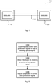
- Fig. 1 schematically illustrates a communications network 100 for utility communications.
- the communications network 100 comprises two stations 110, 120 operatively connected by an optical fiber 130.
- Each station 110, 120 comprises a transmitter 200 and a receiver 300 for transmitting and receiving signals over the optical fiber 130.
- Utility communications today typically use dedicated optical links for transmission of low-speed (typically in the order of 2 Megabits per second, Mb/s) control and protection services between the stations 110, 120.
- Mb/s Megabits per second
- WDM wavelength division multiplexing
- a transmitter 200 a method performed by the transmitter 200, a computer program product comprising code, for example in the form of a computer program, that when run on the transmitter, causes the transmitter to perform the method.
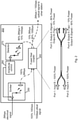
- Fig. 2 schematically illustrates the transmitter 200 of the communications network 100 for utility communications.
- Fig. 2 schematically illustrates how a control and protection signal for utility communications can be superimposed on top of an existing optical signal.
- the control and protection signal is a 2 Mbps electrical signal and the existing optical signal is a 10 Gbps optical signal.
- the transmitter 200 comprises an emitter 250 arranged to convert the electrical control and protection signal to an optical control and protection signal.
- the transmitter 200 comprises a fused fiber coupler 280 arranged to superimpose the optical control and protection signal on the existing optical signal to form a composite optical signal to be transmitted to another station.
- the fused coupler 280 generally comprises two, parallel, optical fibers that have been twisted, stretched, and fused together so that their cores are very close to each other. This forms a coupling region where light from one fiber is coupled over to the other. There are variants of fused fiber couplers with e.g. different coupling ratios.
- the fused fiber coupler 280 comprises four ports, denoted Port 1, Port 2, Port 3, and Port 4. In this example Port 1 and Port 2 are input ports, and Port 3 and Port 4 are output ports. One of the output ports are used to drain a portion of the transmitted composite signal.
- the transmitter 200 comprises a detector 270 arranged to convert the drained portion of the optical composite signal to an electrical signal.
- the transmitter 200 comprises an amplitude controller 260 arranged to adapt the amplitude of the control and protection signal based on the drained portion of the composite signal.
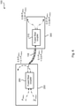
- Fig. 3 schematically illustrates the receiver 300 of the communications network 100 for utility communications. It can be assumed that the optical signal received from another station is a composite optical signal having been generated as described with reference to Fig. 2 .
- the receiver 300 comprises a fused fiber coupler 310 arranged to receive the composite optical signal from another station.
- the fused fiber coupler 310 utilizes three ports, denoted Port 1, Port 3, and Port 4.
- Port 1 is an input port
- Port 3 and Port 4 are output ports.
- One of the output ports are used to drain a portion of the received composite signal.
- the receiver 300 comprises a detector 320 arranged to convert the drained portion into an electrical signal.
- control and protection signal is 10% of the amplitude of the existing optical signal (with a fiber coupler with 90:10 ratio). At the receiver end another 90% is lost in the port connected to the detector 320. This means that the signal level of the superimposed control and protection signal, at the detector 320, is 20dB lower than the existing optical signal.
- the bandwidth of the control and protection signal is low so a high sensitivity (e.g. large detector surface avalanche photo diode) and a high gain amplifier can be used in the detector 320.
- the receiver 300 comprises an extractor 330 arranged to extract the control and protection signal from the drained portion of the composite signal.
- Fig. 4 schematically illustrates a station 110, 120 in the communications network 100 for utility communications, where the station 110, 120 comprises components of both the transmitter 200 as described above and components of the receiver 300 as described above.
- the station 110, 120 comprises an emitter 250 arranged to convert the electrical control and protection signal to an optical control and protection signal.
- the station 110, 120 200 comprises a fused fiber coupler 280 arranged to superimpose the optical control and protection signal on the existing optical signal to form a composite optical signal to be transmitted to another station.
- the station 110, 120 comprises a detector 270 arranged to convert a drained portion of the optical composite signal to an electrical signal.
- the station 110, 120 comprises an amplitude controller 260 arranged to adapt the amplitude of the superimposed control and protection signal based on the drained portion of the composite signal.
- the station 110, 120 further comprises a fused fiber coupler 310 arranged to receive a composite optical signal from another station.
- the station 110, 120 comprises a detector 320 arranged to convert the drained portion into an electrical signal.
- the station 110, 120 comprises an extractor 330 arranged to extract the control and protection signal from the drained portion.
- Fig. 5 is a flow chart illustrating an embodiment of a method for utility communications. The method is performed by the transmitter 200. The method is advantageously provided as a computer program 320.
- the transmitter 200 superimposes a control and protection signal for utility communications on top of an existing optical signal to form a composite signal.
- the existing optical signal is transmitted over an optical fiber.
- the control and protection signal has lower bit rate than the existing optical signal.
- the transmitter 200 obtains feedback by draining a portion of the composite signal from the optical fiber.
- the transmitter 200 adjusts amplitude of the control and protection signal according to the drained portion of the composite signal.
- the composite signal is transmitted from the transmitter 200 to the receiver 300.
- the transmitter 200 may be part of a transmitting station in the communications network 100.
- the receiver 300 may be part of a receiving station in the communications network 100.
- the composite signal is transmitted between a transmitting station 110 and a receiving station 120 in a power system.
- the transmitter 200 is part of the transmitting station 110 and the receiver is part of the receiving station 120.
- the superimposed control and protection signal should not be higher in amplitude than e.g. 10% of the Optical Modulation Amplitude of the existing optical signal.
- the amplitude of the existing optical signal can vary (such as in the order of several dBs according to a small form-factor pluggable (SFP) transceiver specification) and the amplitude of the control and protection signal is hence be adapted, as in step S106.
- a fused fiber coupler has a tap port which can be used as feedback to control the amplitude of the superimposed control and protection signal in step S106.
- the signal from the tap port could be passed through a low-pass filter and from this signal the amplitude of the existing optical signal as well as the superimposed control and protection signal can be extracted and then used to control the amplitude of the control and protection signal to a suitable level.
- the amplitude of the control and protection signal is thus adjusted with respect to reception of the composite signal.
- the composite signal is intended to be received by the receiver 300.
- the amplitude of the control and protection could be adjusted such that it is below an upper threshold of the receiver 300 of the existing optical signal. Further, the amplitude of the control and protection could be adjusted such that it is above a lower threshold of the receiver 300 of the control and protection signal.
- the drained portion thus corresponds to 10% in terms of power of the composite signal (at the transmitter 200). This is illustrated in Fig.
- x ⁇ P 2Mb/s +y ⁇ P 10Gb/s indicates a relative power contribution of x ⁇ 100% from the control and protection signal and a relative power contribution of y ⁇ 100% from the existing optical signal.
- Figs. 7 and 8 are schematic illustrations of signal levels according to embodiments.
- Fig. 7 illustrates the separated signal level amplitudes of the control and protection signal 710 drained to the feedback and the existing optical signal 720.
- a fused fiber coupler with a ratio of 90:10 is used and the input signals (i.e., the control and protection signal and the existing optical signal) are equally strong. Note that the signal levels are only relative and not absolute.
- Fig. 8 illustrates the drained composite signal 810 used for amplitude control of the control and protection signal.
- the drained composite signal 810 is filtered with a low-pass filter and the minimum and maximum level of the thus filtered signal 820 is measured. As can be seen the minimum level is equal to half the level the drained composite signal 810, which with a 90:10 fiber coupler then corresponds to a total of 1/20 of the original input power of the existing optical.
- bit rate of the control and protection signal is at least one order of magnitude lower than the bit rate of the existing optical signal.
- the bit rate of the control and protection signal could be lower than 5 Gb/s, such as between 1.5 Mb/s and 2.5 Mb/s, preferably around 2 Mb/s.
- the bit rate of the existing optical signal could be higher than 5 Gb/s, such as between 5 Gb/s and 15 Gb/s, preferably around 10 Gb/s.
- pre-requisites for the utility communications are used for determining the bandwidths of the control and protection signal and the existing optical signal.
- the existing optical signal is a telecommunications service signal.
- Fig. 9 schematically illustrates, in terms of a number of functional units, the components of a transmitter 200 according to an embodiment.
- Processing circuitry 210 is provided using any combination of one or more of a suitable central processing unit (CPU), multiprocessor, microcontroller, digital signal processor (DSP), etc., capable of executing software instructions stored in a computer program product 310 (as in Fig. 11 ), e.g. in the form of a storage medium 230.
- the processing circuitry 210 may further be provided as at least one application specific integrated circuit (ASIC), or field programmable gate array (FPGA).
- ASIC application specific integrated circuit
- FPGA field programmable gate array
- the processing circuitry 210 is configured to cause the transmitter 200 to perform a set of operations, or steps, S102-S106, as disclosed above.
- the storage medium 230 may store the set of operations
- the processing circuitry 210 may be configured to retrieve the set of operations from the storage medium 230 to cause the transmitter 200 to perform the set of operations.
- the set of operations may be provided as a set of executable instructions.
- the processing circuitry 210 is thereby arranged to execute methods as herein disclosed.
- the storage medium 230 may also comprise persistent storage, which, for example, can be any single one or combination of magnetic memory, optical memory, solid state memory or even remotely mounted memory.
- the transmitter 200 may further comprise a communications interface 220 at least configured for communications with other entities and devices in the communications system 100, 100a, 100b.
- the communications interface 220 may comprise one or more transmitters and receivers, comprising analogue and digital components.
- the processing circuitry 210 controls the general operation of the transmitter 200 e.g. by sending data and control signals to the communications interface 220 and the storage medium 230, by receiving data and reports from the communications interface 220, and by retrieving data and instructions from the storage medium 230.
- Other components, as well as the related functionality, of the transmitter 200 are omitted in order not to obscure the concepts presented herein.
- Fig. 10 schematically illustrates, in terms of a number of functional modules, the components of a transmitter 200 according to an embodiment.
- the transmitter 200 of Fig. 10 comprises a number of functional modules; a superimpose module 210a configured to perform step S102, an obtain module 210b configured to perform step S104, and an adjust module 210c configured to perform step S106.
- the transmitter 200 of Fig. 10 may further comprises a number of optional functional modules.
- each functional module 210a-210c may in one embodiment be implemented only in hardware or and in another embodiment with the help of software, i.e., the latter embodiment having computer program instructions stored on the storage medium 230 which when run on the processing circuitry makes the transmitter 200 perform the corresponding steps mentioned above in conjunction with Fig 6 .
- modules 210a-210c may be implemented by the processing circuitry 210, possibly in cooperation with functional units 220 and/or 230.
- the processing circuitry 210 may thus be configured to from the storage medium 230 fetch instructions as provided by a functional module 210a-210c and to execute these instructions, thereby performing any steps as disclosed herein.
- Fig. 11 shows one example of a computer program product 310 comprising computer readable storage medium 330.
- a computer program 320 can be stored, which computer program 320 can cause the processing circuitry 210 and thereto operatively coupled entities and devices, such as the communications interface 220 and the storage medium 230, to execute methods according to embodiments described herein.
- the computer program 320 and/or computer program product 310 may thus provide means for performing any steps as herein disclosed.
- the computer program product 310 is illustrated as an optical disc, such as a CD (compact disc) or a DVD (digital versatile disc) or a Blu-Ray disc.
- the computer program product 310 could also be embodied as a memory, such as a random access memory (RAM), a read-only memory (ROM), an erasable programmable read-only memory (EPROM), or an electrically erasable programmable read-only memory (EEPROM) and more particularly as a non-volatile storage medium of a device in an external memory such as a USB (Universal Serial Bus) memory or a Flash memory, such as a compact Flash memory.
- the computer program 320 is here schematically shown as a track on the depicted optical disk, the computer program 320 can be stored in any way which is suitable for the computer program product 310.
Landscapes
- Physics & Mathematics (AREA)
- Electromagnetism (AREA)
- Engineering & Computer Science (AREA)
- Computer Networks & Wireless Communication (AREA)
- Signal Processing (AREA)
- Optical Communication System (AREA)
Claims (12)
- Verfahren für eine Versorgungskommunikation, wobei das Verfahren von einem Sender (200) durchgeführt wird, wobei das Verfahren durch Folgendes gekennzeichnet ist:Überlagern (S102) eines Telekommunikationssignals, das über einen Lichtleiter (130) übertragen wird, durch ein Steuer- und Schutzsignal für die Versorgungskommunikation, um ein zusammengesetztes Signal zu bilden, wobei das Steuer- und Schutzsignal eine niedrigere Bitrate aufweist als das Telekommunikationssignal und wobei die Versorgungskommunikation eine Fernsteuerung von unbemannten Stationen und eine Übermittlung von Daten und Lastwerten betrifft;Erhalten (S104) einer Rückkopplung durch Abführen eines Abschnitts des zusammengesetzten Signals aus dem Lichtleiter undAnpassen (S106) einer Amplitude des Steuer- und Schutzsignals gemäß dem Abschnitt des zusammengesetzten Signals, derart, dass die Amplitude des Steuer- und Schutzsignals an eine Schwankung der Amplitude des Telekommunikationssignals angepasst wird und 10 % der optischen Modulationsamplitude des Telekommunikationssignals nicht überschreitet.
- Verfahren nach Anspruch 1, wobei die Amplitude des Steuer- und Schutzsignals mit Bezug auf den Empfang des zusammengesetzten Signals weiter angepasst wird.
- Verfahren nach Anspruch 1, wobei die Amplitude des Steuer- und Schutzsignals derart angepasst wird, dass sie über einem unteren Schwellwert eines Empfängers (300) des Steuer- und Schutzsignals liegt.
- Verfahren nach Anspruch 1, wobei das zusammengesetzte Signal zwischen einer Sendestation (110) und einer Empfangsstation (120) in einem Energiesystem übertragen wird.
- Verfahren nach Anspruch 4, wobei der Sender (200) Teil der Sendestation (110) ist.
- Verfahren nach Anspruch 4 oder 5, wobei der Empfänger (300) Teil der Empfangsstation (120) ist.
- Verfahren nach Anspruch 1, wobei der Abschnitt bezogen auf die Energie des zusammengesetzten Signals 10 % entspricht.
- Verfahren nach Anspruch 1, wobei die Bitrate des Steuer- und Schutzsignals um mindestens eine Größenordnung niedriger ist als die Bitrate des Telekommunikationssignals.
- Verfahren nach Anspruch 1, wobei die Bitrate des Steuer- und Schutzsignals 2 Mb/s beträgt.
- Verfahren nach Anspruch 1, wobei die Bitrate des Telekommunikationssignals 10 Gb/s beträgt.
- Sender (200) für die Versorgungskommunikation, wobei der Sender eine Verarbeitungsschaltung (210) umfasst, dadurch gekennzeichnet, dass die Verarbeitungsschaltung dazu ausgelegt ist, den Sender zu Folgendem zu veranlassen:Überlagern eines Telekommunikationssignals, das über einen Lichtleiter (130) übertragen wird, durch ein Steuer- und Schutzsignal für die Versorgungskommunikation, um ein zusammengesetztes Signal zu bilden, wobei das Steuer- und Schutzsignal eine niedrigere Bitrate aufweist als das Telekommunikationssignal und wobei die Versorgungskommunikation eine Fernsteuerung von unbemannten Stationen und eine Übermittlung von Daten und Lastwerten betrifft;Erhalten einer Rückkopplung durch Abführen eines Abschnitts des zusammengesetzten Signals aus dem Lichtleiter undAnpassen einer Amplitude des Steuer- und Schutzsignals gemäß dem Abschnitt des zusammengesetzten Signals, derart, dass die Amplitude des Steuer- und Schutzsignals an eine Schwankung der Amplitude des Telekommunikationssignals angepasst wird und 10 % der optischen Modulationsamplitude des Telekommunikationssignals nicht überschreitet.
- Computerprogramm (320) für die Versorgungskommunikation, dadurch gekennzeichnet, dass das Computerprogramm Computercode umfasst, der, wenn er auf der Verarbeitungsschaltung (210) eines Senders (200) ausgeführt wird, den Sender zu Folgendem veranlasst:Überlagern (S102) eines Telekommunikationssignals, das über einen Lichtleiter (130) übertragen wird, durch ein Steuer- und Schutzsignal für die Versorgungskommunikation, um ein zusammengesetztes Signal zu bilden, wobei das Steuer- und Schutzsignal eine niedrigere Bitrate aufweist als das Telekommunikationssignal und wobei die Versorgungskommunikation eine Fernsteuerung von unbemannten Stationen und eine Übermittlung von Daten und Lastwerten betrifft;Erhalten (S104) einer Rückkopplung durch Abführen eines Abschnitts des zusammengesetzten Signals aus dem Lichtleiter und Anpassen (S106) einer Amplitude des Steuer- und Schutzsignals gemäß dem Abschnitt des zusammengesetzten Signals, derart, dass die Amplitude des Steuer- und Schutzsignals an eine Schwankung der Amplitude des Telekommunikationssignals angepasst wird und 10 % der optischen Modulationsamplitude des Telekommunikationssignals nicht überschreitet.
Applications Claiming Priority (1)
| Application Number | Priority Date | Filing Date | Title |
|---|---|---|---|
| PCT/EP2016/066607 WO2018010779A1 (en) | 2016-07-13 | 2016-07-13 | Utility communications using optical fibers |
Publications (2)
| Publication Number | Publication Date |
|---|---|
| EP3485587A1 EP3485587A1 (de) | 2019-05-22 |
| EP3485587B1 true EP3485587B1 (de) | 2022-03-02 |
Family
ID=56550198
Family Applications (1)
| Application Number | Title | Priority Date | Filing Date |
|---|---|---|---|
| EP16742206.2A Active EP3485587B1 (de) | 2016-07-13 | 2016-07-13 | Versorgungsnetzkommunikation mit glasfasern |
Country Status (4)
| Country | Link |
|---|---|
| US (1) | US10623093B2 (de) |
| EP (1) | EP3485587B1 (de) |
| CN (1) | CN109478927B (de) |
| WO (1) | WO2018010779A1 (de) |
Family Cites Families (15)
| Publication number | Priority date | Publication date | Assignee | Title |
|---|---|---|---|---|
| US5383046A (en) * | 1992-05-29 | 1995-01-17 | Fujitsu Limited | Supervisory and control signal transmitting system for use in optically amplifying repeaters system |
| US5448629A (en) * | 1993-10-14 | 1995-09-05 | At&T Corp. | Amplitude detection scheme for optical transmitter control |
| JP3858451B2 (ja) * | 1998-06-03 | 2006-12-13 | Kddi株式会社 | 制御信号重畳装置 |
| GB9813412D0 (en) * | 1998-06-23 | 1998-08-19 | Cambrian Systems Corp | Optical FSK modulation and demodulation based on the thermal chirp for optical path overhead transfer using asymmetrical mach-zehnder interferometer |
| US7209660B1 (en) * | 1999-12-29 | 2007-04-24 | Forster Energy Llc | Optical communications using heterodyne detection |
| CN101053209A (zh) * | 2004-07-02 | 2007-10-10 | 最优许可公司 | 介质到不同介质跳跃网状网络 |
| EP2115397B1 (de) * | 2007-02-02 | 2017-08-09 | Aztech Associates Inc. | Versorgungs-überwachungseinrichtung, system und verfahren |
| BRPI0700838A (pt) | 2007-03-20 | 2008-11-04 | Eduardo Pedrosa Santos | sistema para aquisição de dados e multiplicação de contatos de sinalização e proteção em equipamentos de subestações e usinas de energia elétrica e congêneres |
| WO2009054928A2 (en) * | 2007-10-19 | 2009-04-30 | Keep In Touch Systems, Inc. | System and method for time sensitive scheduling data privacy protection |
| CN101729185B (zh) * | 2008-10-21 | 2013-06-05 | 华为技术有限公司 | 光信号的标识或检测方法、装置以及标识及检测系统 |
| WO2010073392A1 (ja) * | 2008-12-26 | 2010-07-01 | 富士通株式会社 | 光信号発生装置及びその調整方法 |
| US8798467B2 (en) | 2012-06-26 | 2014-08-05 | The Boeing Company | Optical coupler testing system |
| US9817189B2 (en) * | 2013-07-01 | 2017-11-14 | Tongqing Wang | Digital dispersion compensation module |
| CN205212836U (zh) * | 2015-12-15 | 2016-05-04 | 付亮 | 一种光纤通信装置 |
| US10230472B2 (en) * | 2016-06-08 | 2019-03-12 | Subcom, Llc | Polarization modulation of supervisory signals for reducing interference with data signals |
-
2016
- 2016-07-13 EP EP16742206.2A patent/EP3485587B1/de active Active
- 2016-07-13 CN CN201680087550.9A patent/CN109478927B/zh active Active
- 2016-07-13 US US16/317,407 patent/US10623093B2/en active Active
- 2016-07-13 WO PCT/EP2016/066607 patent/WO2018010779A1/en not_active Ceased
Non-Patent Citations (1)
| Title |
|---|
| None * |
Also Published As
| Publication number | Publication date |
|---|---|
| CN109478927B (zh) | 2021-10-22 |
| CN109478927A (zh) | 2019-03-15 |
| US20190326985A1 (en) | 2019-10-24 |
| EP3485587A1 (de) | 2019-05-22 |
| US10623093B2 (en) | 2020-04-14 |
| WO2018010779A1 (en) | 2018-01-18 |
Similar Documents
| Publication | Publication Date | Title |
|---|---|---|
| US7326916B2 (en) | Optical submarine transmission system | |
| US8208807B2 (en) | Transmission of eye information from opto-electronic modules | |
| US10659186B2 (en) | Multiplexing two separate optical links with the same wavelength using asymmetric combining and splitting | |
| CN110176960A (zh) | 一种新型单纤双向多通道输入光模块 | |
| US7209667B2 (en) | Methods of connecting and testing interfaces for CWDM fiber-optic systems | |
| KR101530655B1 (ko) | 단일의 바이 패스용 광 스위치를 구비한 광신호 송수신 네트워크 단말장치 및 그를 포함하는 단일 광섬유 라인 광 네트워크 이더넷 시스템 | |
| US7010233B2 (en) | Interface device for a fiberoptic communication network and methods of using such a device | |
| EP3114778B1 (de) | Sendeempfänger und verfahren zur überwachung der scm-übertragung auf glasfaserkabel | |
| EP3485587B1 (de) | Versorgungsnetzkommunikation mit glasfasern | |
| US20140363161A1 (en) | Optical signal switching device and optical transmission system | |
| EP3754871B1 (de) | Anordnung für optische übertragung | |
| JP2022126601A (ja) | 光通信装置の自動波長設定システム | |
| KR20150146102A (ko) | 파장 가변 필터를 이용한 송수신 장치 및 송수신 방법 | |
| US10707956B1 (en) | Active fiber tap | |
| KR102291600B1 (ko) | 광섬유 증폭장치 및 그 동작 방법 | |
| US12284467B2 (en) | Optical network configuration | |
| KR102343878B1 (ko) | 광분기 결합기를 이용한 광트랜시버 관리 장치 및 방법 | |
| CN209676247U (zh) | 一种新型单纤双向多通道输入光模块 | |
| KR102135852B1 (ko) | 광통신 구간의 광 선로거리 확장 및 단 파장의 광레벨 보상을 위한 정합 장치 | |
| US10551309B2 (en) | Method and system to improve scheme of optical network cable and audio cable | |
| TWI416882B (zh) | 光纖控制裝置、光纖通訊網路及光纖通訊網路的使用方法 | |
| KR20150090671A (ko) | 양방향 단일 광섬유 파장분할다중 고리형 네트워크의 보호 절체를 위한 원격지 노드 및 국사용 노드 | |
| EP2747310A1 (de) | Optische Datenübertragungsvorrichtung | |
| EP0734127A1 (de) | Einrichtung zur digitalen Übertragung über Lichtleitfasern | |
| CN102413390A (zh) | 用于连接olt和pos的光通信设备 |
Legal Events
| Date | Code | Title | Description |
|---|---|---|---|
| STAA | Information on the status of an ep patent application or granted ep patent |
Free format text: STATUS: THE INTERNATIONAL PUBLICATION HAS BEEN MADE |
|
| PUAI | Public reference made under article 153(3) epc to a published international application that has entered the european phase |
Free format text: ORIGINAL CODE: 0009012 |
|
| STAA | Information on the status of an ep patent application or granted ep patent |
Free format text: STATUS: REQUEST FOR EXAMINATION WAS MADE |
|
| 17P | Request for examination filed |
Effective date: 20190213 |
|
| AK | Designated contracting states |
Kind code of ref document: A1 Designated state(s): AL AT BE BG CH CY CZ DE DK EE ES FI FR GB GR HR HU IE IS IT LI LT LU LV MC MK MT NL NO PL PT RO RS SE SI SK SM TR |
|
| AX | Request for extension of the european patent |
Extension state: BA ME |
|
| DAV | Request for validation of the european patent (deleted) | ||
| DAX | Request for extension of the european patent (deleted) | ||
| RAP1 | Party data changed (applicant data changed or rights of an application transferred) |
Owner name: ABB POWER GRIDS SWITZERLAND AG |
|
| GRAP | Despatch of communication of intention to grant a patent |
Free format text: ORIGINAL CODE: EPIDOSNIGR1 |
|
| STAA | Information on the status of an ep patent application or granted ep patent |
Free format text: STATUS: GRANT OF PATENT IS INTENDED |
|
| INTG | Intention to grant announced |
Effective date: 20210728 |
|
| GRAS | Grant fee paid |
Free format text: ORIGINAL CODE: EPIDOSNIGR3 |
|
| RAP3 | Party data changed (applicant data changed or rights of an application transferred) |
Owner name: HITACHI ENERGY SWITZERLAND AG |
|
| GRAA | (expected) grant |
Free format text: ORIGINAL CODE: 0009210 |
|
| STAA | Information on the status of an ep patent application or granted ep patent |
Free format text: STATUS: THE PATENT HAS BEEN GRANTED |
|
| AK | Designated contracting states |
Kind code of ref document: B1 Designated state(s): AL AT BE BG CH CY CZ DE DK EE ES FI FR GB GR HR HU IE IS IT LI LT LU LV MC MK MT NL NO PL PT RO RS SE SI SK SM TR |
|
| REG | Reference to a national code |
Ref country code: GB Ref legal event code: FG4D |
|
| REG | Reference to a national code |
Ref country code: CH Ref legal event code: EP Ref country code: AT Ref legal event code: REF Ref document number: 1473115 Country of ref document: AT Kind code of ref document: T Effective date: 20220315 |
|
| REG | Reference to a national code |
Ref country code: DE Ref legal event code: R096 Ref document number: 602016069589 Country of ref document: DE |
|
| REG | Reference to a national code |
Ref country code: IE Ref legal event code: FG4D |
|
| REG | Reference to a national code |
Ref country code: LT Ref legal event code: MG9D |
|
| REG | Reference to a national code |
Ref country code: NL Ref legal event code: MP Effective date: 20220302 |
|
| PG25 | Lapsed in a contracting state [announced via postgrant information from national office to epo] |
Ref country code: SE Free format text: LAPSE BECAUSE OF FAILURE TO SUBMIT A TRANSLATION OF THE DESCRIPTION OR TO PAY THE FEE WITHIN THE PRESCRIBED TIME-LIMIT Effective date: 20220302 Ref country code: RS Free format text: LAPSE BECAUSE OF FAILURE TO SUBMIT A TRANSLATION OF THE DESCRIPTION OR TO PAY THE FEE WITHIN THE PRESCRIBED TIME-LIMIT Effective date: 20220302 Ref country code: NO Free format text: LAPSE BECAUSE OF FAILURE TO SUBMIT A TRANSLATION OF THE DESCRIPTION OR TO PAY THE FEE WITHIN THE PRESCRIBED TIME-LIMIT Effective date: 20220602 Ref country code: LT Free format text: LAPSE BECAUSE OF FAILURE TO SUBMIT A TRANSLATION OF THE DESCRIPTION OR TO PAY THE FEE WITHIN THE PRESCRIBED TIME-LIMIT Effective date: 20220302 Ref country code: HR Free format text: LAPSE BECAUSE OF FAILURE TO SUBMIT A TRANSLATION OF THE DESCRIPTION OR TO PAY THE FEE WITHIN THE PRESCRIBED TIME-LIMIT Effective date: 20220302 Ref country code: ES Free format text: LAPSE BECAUSE OF FAILURE TO SUBMIT A TRANSLATION OF THE DESCRIPTION OR TO PAY THE FEE WITHIN THE PRESCRIBED TIME-LIMIT Effective date: 20220302 Ref country code: BG Free format text: LAPSE BECAUSE OF FAILURE TO SUBMIT A TRANSLATION OF THE DESCRIPTION OR TO PAY THE FEE WITHIN THE PRESCRIBED TIME-LIMIT Effective date: 20220602 |
|
| REG | Reference to a national code |
Ref country code: AT Ref legal event code: MK05 Ref document number: 1473115 Country of ref document: AT Kind code of ref document: T Effective date: 20220302 |
|
| PG25 | Lapsed in a contracting state [announced via postgrant information from national office to epo] |
Ref country code: PL Free format text: LAPSE BECAUSE OF FAILURE TO SUBMIT A TRANSLATION OF THE DESCRIPTION OR TO PAY THE FEE WITHIN THE PRESCRIBED TIME-LIMIT Effective date: 20220302 Ref country code: LV Free format text: LAPSE BECAUSE OF FAILURE TO SUBMIT A TRANSLATION OF THE DESCRIPTION OR TO PAY THE FEE WITHIN THE PRESCRIBED TIME-LIMIT Effective date: 20220302 Ref country code: GR Free format text: LAPSE BECAUSE OF FAILURE TO SUBMIT A TRANSLATION OF THE DESCRIPTION OR TO PAY THE FEE WITHIN THE PRESCRIBED TIME-LIMIT Effective date: 20220603 Ref country code: FI Free format text: LAPSE BECAUSE OF FAILURE TO SUBMIT A TRANSLATION OF THE DESCRIPTION OR TO PAY THE FEE WITHIN THE PRESCRIBED TIME-LIMIT Effective date: 20220302 |
|
| PG25 | Lapsed in a contracting state [announced via postgrant information from national office to epo] |
Ref country code: NL Free format text: LAPSE BECAUSE OF FAILURE TO SUBMIT A TRANSLATION OF THE DESCRIPTION OR TO PAY THE FEE WITHIN THE PRESCRIBED TIME-LIMIT Effective date: 20220302 |
|
| PG25 | Lapsed in a contracting state [announced via postgrant information from national office to epo] |
Ref country code: SM Free format text: LAPSE BECAUSE OF FAILURE TO SUBMIT A TRANSLATION OF THE DESCRIPTION OR TO PAY THE FEE WITHIN THE PRESCRIBED TIME-LIMIT Effective date: 20220302 Ref country code: SK Free format text: LAPSE BECAUSE OF FAILURE TO SUBMIT A TRANSLATION OF THE DESCRIPTION OR TO PAY THE FEE WITHIN THE PRESCRIBED TIME-LIMIT Effective date: 20220302 Ref country code: RO Free format text: LAPSE BECAUSE OF FAILURE TO SUBMIT A TRANSLATION OF THE DESCRIPTION OR TO PAY THE FEE WITHIN THE PRESCRIBED TIME-LIMIT Effective date: 20220302 Ref country code: PT Free format text: LAPSE BECAUSE OF FAILURE TO SUBMIT A TRANSLATION OF THE DESCRIPTION OR TO PAY THE FEE WITHIN THE PRESCRIBED TIME-LIMIT Effective date: 20220704 Ref country code: EE Free format text: LAPSE BECAUSE OF FAILURE TO SUBMIT A TRANSLATION OF THE DESCRIPTION OR TO PAY THE FEE WITHIN THE PRESCRIBED TIME-LIMIT Effective date: 20220302 Ref country code: CZ Free format text: LAPSE BECAUSE OF FAILURE TO SUBMIT A TRANSLATION OF THE DESCRIPTION OR TO PAY THE FEE WITHIN THE PRESCRIBED TIME-LIMIT Effective date: 20220302 Ref country code: AT Free format text: LAPSE BECAUSE OF FAILURE TO SUBMIT A TRANSLATION OF THE DESCRIPTION OR TO PAY THE FEE WITHIN THE PRESCRIBED TIME-LIMIT Effective date: 20220302 |
|
| PG25 | Lapsed in a contracting state [announced via postgrant information from national office to epo] |
Ref country code: IS Free format text: LAPSE BECAUSE OF FAILURE TO SUBMIT A TRANSLATION OF THE DESCRIPTION OR TO PAY THE FEE WITHIN THE PRESCRIBED TIME-LIMIT Effective date: 20220702 Ref country code: AL Free format text: LAPSE BECAUSE OF FAILURE TO SUBMIT A TRANSLATION OF THE DESCRIPTION OR TO PAY THE FEE WITHIN THE PRESCRIBED TIME-LIMIT Effective date: 20220302 |
|
| REG | Reference to a national code |
Ref country code: DE Ref legal event code: R097 Ref document number: 602016069589 Country of ref document: DE |
|
| PLBE | No opposition filed within time limit |
Free format text: ORIGINAL CODE: 0009261 |
|
| STAA | Information on the status of an ep patent application or granted ep patent |
Free format text: STATUS: NO OPPOSITION FILED WITHIN TIME LIMIT |
|
| PG25 | Lapsed in a contracting state [announced via postgrant information from national office to epo] |
Ref country code: DK Free format text: LAPSE BECAUSE OF FAILURE TO SUBMIT A TRANSLATION OF THE DESCRIPTION OR TO PAY THE FEE WITHIN THE PRESCRIBED TIME-LIMIT Effective date: 20220302 |
|
| 26N | No opposition filed |
Effective date: 20221205 |
|
| PG25 | Lapsed in a contracting state [announced via postgrant information from national office to epo] |
Ref country code: SI Free format text: LAPSE BECAUSE OF FAILURE TO SUBMIT A TRANSLATION OF THE DESCRIPTION OR TO PAY THE FEE WITHIN THE PRESCRIBED TIME-LIMIT Effective date: 20220302 Ref country code: MC Free format text: LAPSE BECAUSE OF FAILURE TO SUBMIT A TRANSLATION OF THE DESCRIPTION OR TO PAY THE FEE WITHIN THE PRESCRIBED TIME-LIMIT Effective date: 20220302 |
|
| REG | Reference to a national code |
Ref country code: CH Ref legal event code: PL |
|
| REG | Reference to a national code |
Ref country code: BE Ref legal event code: MM Effective date: 20220731 |
|
| PG25 | Lapsed in a contracting state [announced via postgrant information from national office to epo] |
Ref country code: LU Free format text: LAPSE BECAUSE OF NON-PAYMENT OF DUE FEES Effective date: 20220713 Ref country code: LI Free format text: LAPSE BECAUSE OF NON-PAYMENT OF DUE FEES Effective date: 20220731 Ref country code: CH Free format text: LAPSE BECAUSE OF NON-PAYMENT OF DUE FEES Effective date: 20220731 |
|
| PG25 | Lapsed in a contracting state [announced via postgrant information from national office to epo] |
Ref country code: BE Free format text: LAPSE BECAUSE OF NON-PAYMENT OF DUE FEES Effective date: 20220731 |
|
| P01 | Opt-out of the competence of the unified patent court (upc) registered |
Effective date: 20230527 |
|
| PG25 | Lapsed in a contracting state [announced via postgrant information from national office to epo] |
Ref country code: IT Free format text: LAPSE BECAUSE OF FAILURE TO SUBMIT A TRANSLATION OF THE DESCRIPTION OR TO PAY THE FEE WITHIN THE PRESCRIBED TIME-LIMIT Effective date: 20220302 Ref country code: IE Free format text: LAPSE BECAUSE OF NON-PAYMENT OF DUE FEES Effective date: 20220713 |
|
| PG25 | Lapsed in a contracting state [announced via postgrant information from national office to epo] |
Ref country code: HU Free format text: LAPSE BECAUSE OF FAILURE TO SUBMIT A TRANSLATION OF THE DESCRIPTION OR TO PAY THE FEE WITHIN THE PRESCRIBED TIME-LIMIT; INVALID AB INITIO Effective date: 20160713 |
|
| REG | Reference to a national code |
Ref country code: DE Ref legal event code: R081 Ref document number: 602016069589 Country of ref document: DE Owner name: HITACHI ENERGY LTD, CH Free format text: FORMER OWNER: HITACHI ENERGY SWITZERLAND AG, BADEN, CH |
|
| PG25 | Lapsed in a contracting state [announced via postgrant information from national office to epo] |
Ref country code: MK Free format text: LAPSE BECAUSE OF FAILURE TO SUBMIT A TRANSLATION OF THE DESCRIPTION OR TO PAY THE FEE WITHIN THE PRESCRIBED TIME-LIMIT Effective date: 20220302 Ref country code: CY Free format text: LAPSE BECAUSE OF FAILURE TO SUBMIT A TRANSLATION OF THE DESCRIPTION OR TO PAY THE FEE WITHIN THE PRESCRIBED TIME-LIMIT Effective date: 20220302 |
|
| REG | Reference to a national code |
Ref country code: GB Ref legal event code: 732E Free format text: REGISTERED BETWEEN 20240718 AND 20240724 |
|
| PG25 | Lapsed in a contracting state [announced via postgrant information from national office to epo] |
Ref country code: MT Free format text: LAPSE BECAUSE OF FAILURE TO SUBMIT A TRANSLATION OF THE DESCRIPTION OR TO PAY THE FEE WITHIN THE PRESCRIBED TIME-LIMIT Effective date: 20220302 |
|
| REG | Reference to a national code |
Ref country code: DE Ref legal event code: R082 Ref document number: 602016069589 Country of ref document: DE Representative=s name: DENNEMEYER & ASSOCIATES RECHTSANWALTSGESELLSCH, DE |
|
| PGFP | Annual fee paid to national office [announced via postgrant information from national office to epo] |
Ref country code: DE Payment date: 20250722 Year of fee payment: 10 |
|
| PGFP | Annual fee paid to national office [announced via postgrant information from national office to epo] |
Ref country code: GB Payment date: 20250722 Year of fee payment: 10 |
|
| PGFP | Annual fee paid to national office [announced via postgrant information from national office to epo] |
Ref country code: FR Payment date: 20250725 Year of fee payment: 10 |
|
| PG25 | Lapsed in a contracting state [announced via postgrant information from national office to epo] |
Ref country code: TR Free format text: LAPSE BECAUSE OF FAILURE TO SUBMIT A TRANSLATION OF THE DESCRIPTION OR TO PAY THE FEE WITHIN THE PRESCRIBED TIME-LIMIT Effective date: 20220302 |