EP3485523B1 - Batteriehalter - Google Patents
Batteriehalter Download PDFInfo
- Publication number
- EP3485523B1 EP3485523B1 EP17764479.6A EP17764479A EP3485523B1 EP 3485523 B1 EP3485523 B1 EP 3485523B1 EP 17764479 A EP17764479 A EP 17764479A EP 3485523 B1 EP3485523 B1 EP 3485523B1
- Authority
- EP
- European Patent Office
- Prior art keywords
- housing component
- battery
- flexible
- side wall
- holder assembly
- Prior art date
- Legal status (The legal status is an assumption and is not a legal conclusion. Google has not performed a legal analysis and makes no representation as to the accuracy of the status listed.)
- Active
Links
Images






Classifications
-
- H—ELECTRICITY
- H01—ELECTRIC ELEMENTS
- H01M—PROCESSES OR MEANS, e.g. BATTERIES, FOR THE DIRECT CONVERSION OF CHEMICAL ENERGY INTO ELECTRICAL ENERGY
- H01M50/00—Constructional details or processes of manufacture of the non-active parts of electrochemical cells other than fuel cells, e.g. hybrid cells
- H01M50/20—Mountings; Secondary casings or frames; Racks, modules or packs; Suspension devices; Shock absorbers; Transport or carrying devices; Holders
-
- H—ELECTRICITY
- H01—ELECTRIC ELEMENTS
- H01M—PROCESSES OR MEANS, e.g. BATTERIES, FOR THE DIRECT CONVERSION OF CHEMICAL ENERGY INTO ELECTRICAL ENERGY
- H01M50/00—Constructional details or processes of manufacture of the non-active parts of electrochemical cells other than fuel cells, e.g. hybrid cells
- H01M50/20—Mountings; Secondary casings or frames; Racks, modules or packs; Suspension devices; Shock absorbers; Transport or carrying devices; Holders
- H01M50/204—Racks, modules or packs for multiple batteries or multiple cells
- H01M50/207—Racks, modules or packs for multiple batteries or multiple cells characterised by their shape
- H01M50/213—Racks, modules or packs for multiple batteries or multiple cells characterised by their shape adapted for cells having curved cross-section, e.g. round or elliptic
-
- H—ELECTRICITY
- H01—ELECTRIC ELEMENTS
- H01M—PROCESSES OR MEANS, e.g. BATTERIES, FOR THE DIRECT CONVERSION OF CHEMICAL ENERGY INTO ELECTRICAL ENERGY
- H01M50/00—Constructional details or processes of manufacture of the non-active parts of electrochemical cells other than fuel cells, e.g. hybrid cells
- H01M50/20—Mountings; Secondary casings or frames; Racks, modules or packs; Suspension devices; Shock absorbers; Transport or carrying devices; Holders
- H01M50/233—Mountings; Secondary casings or frames; Racks, modules or packs; Suspension devices; Shock absorbers; Transport or carrying devices; Holders characterised by physical properties of casings or racks, e.g. dimensions
- H01M50/24—Mountings; Secondary casings or frames; Racks, modules or packs; Suspension devices; Shock absorbers; Transport or carrying devices; Holders characterised by physical properties of casings or racks, e.g. dimensions adapted for protecting batteries from their environment, e.g. from corrosion
-
- H—ELECTRICITY
- H01—ELECTRIC ELEMENTS
- H01M—PROCESSES OR MEANS, e.g. BATTERIES, FOR THE DIRECT CONVERSION OF CHEMICAL ENERGY INTO ELECTRICAL ENERGY
- H01M50/00—Constructional details or processes of manufacture of the non-active parts of electrochemical cells other than fuel cells, e.g. hybrid cells
- H01M50/20—Mountings; Secondary casings or frames; Racks, modules or packs; Suspension devices; Shock absorbers; Transport or carrying devices; Holders
- H01M50/249—Mountings; Secondary casings or frames; Racks, modules or packs; Suspension devices; Shock absorbers; Transport or carrying devices; Holders specially adapted for aircraft or vehicles, e.g. cars or trains
-
- H—ELECTRICITY
- H01—ELECTRIC ELEMENTS
- H01M—PROCESSES OR MEANS, e.g. BATTERIES, FOR THE DIRECT CONVERSION OF CHEMICAL ENERGY INTO ELECTRICAL ENERGY
- H01M50/00—Constructional details or processes of manufacture of the non-active parts of electrochemical cells other than fuel cells, e.g. hybrid cells
- H01M50/20—Mountings; Secondary casings or frames; Racks, modules or packs; Suspension devices; Shock absorbers; Transport or carrying devices; Holders
- H01M50/262—Mountings; Secondary casings or frames; Racks, modules or packs; Suspension devices; Shock absorbers; Transport or carrying devices; Holders with fastening means, e.g. locks
-
- H—ELECTRICITY
- H01—ELECTRIC ELEMENTS
- H01M—PROCESSES OR MEANS, e.g. BATTERIES, FOR THE DIRECT CONVERSION OF CHEMICAL ENERGY INTO ELECTRICAL ENERGY
- H01M50/00—Constructional details or processes of manufacture of the non-active parts of electrochemical cells other than fuel cells, e.g. hybrid cells
- H01M50/20—Mountings; Secondary casings or frames; Racks, modules or packs; Suspension devices; Shock absorbers; Transport or carrying devices; Holders
- H01M50/267—Mountings; Secondary casings or frames; Racks, modules or packs; Suspension devices; Shock absorbers; Transport or carrying devices; Holders having means for adapting to batteries or cells of different types or different sizes
-
- H—ELECTRICITY
- H01—ELECTRIC ELEMENTS
- H01M—PROCESSES OR MEANS, e.g. BATTERIES, FOR THE DIRECT CONVERSION OF CHEMICAL ENERGY INTO ELECTRICAL ENERGY
- H01M50/00—Constructional details or processes of manufacture of the non-active parts of electrochemical cells other than fuel cells, e.g. hybrid cells
- H01M50/20—Mountings; Secondary casings or frames; Racks, modules or packs; Suspension devices; Shock absorbers; Transport or carrying devices; Holders
- H01M50/271—Lids or covers for the racks or secondary casings
-
- H—ELECTRICITY
- H01—ELECTRIC ELEMENTS
- H01M—PROCESSES OR MEANS, e.g. BATTERIES, FOR THE DIRECT CONVERSION OF CHEMICAL ENERGY INTO ELECTRICAL ENERGY
- H01M2220/00—Batteries for particular applications
- H01M2220/20—Batteries in motive systems, e.g. vehicle, ship, plane
-
- Y—GENERAL TAGGING OF NEW TECHNOLOGICAL DEVELOPMENTS; GENERAL TAGGING OF CROSS-SECTIONAL TECHNOLOGIES SPANNING OVER SEVERAL SECTIONS OF THE IPC; TECHNICAL SUBJECTS COVERED BY FORMER USPC CROSS-REFERENCE ART COLLECTIONS [XRACs] AND DIGESTS
- Y02—TECHNOLOGIES OR APPLICATIONS FOR MITIGATION OR ADAPTATION AGAINST CLIMATE CHANGE
- Y02E—REDUCTION OF GREENHOUSE GAS [GHG] EMISSIONS, RELATED TO ENERGY GENERATION, TRANSMISSION OR DISTRIBUTION
- Y02E60/00—Enabling technologies; Technologies with a potential or indirect contribution to GHG emissions mitigation
- Y02E60/10—Energy storage using batteries
Definitions
- This invention relates to a battery holder assembly for housing a battery securely.
- the battery To ensure that a battery residing in a battery assembly module does not become dislodged, damaged, or cause damage to other parts of the battery assembly module, the battery must be tightly secured within the battery holder assembly module. In order to achieve such a tight and secure assembly, the battery must not be too big or too small for the space that is designed to house it. If the battery is too big, the components of the battery holder assembly, and the battery itself, can interfere with one another and not allow the battery to make the necessary electrical contacts. On the other hand, if the battery is too small, it may move around within the assembly. This is an especially important consideration for a battery housed in a battery holder assembly module within a device where the battery could potentially get knocked around.
- An exemplary device includes a vehicle telematics system, wherein the battery could potentially get knocked around, especially in the case of a crash scenario.
- designing a battery holder assembly module that has some flexibility between its components may help to compensate for these variations in battery size.
- the degree of flexibility must also be taken into consideration because components that are too flexible will not allow for the battery assembly module and all of it components to withstand a crash scenario for example, because the flexible components may move around when a large amount of force is applied to it.
- a need exists for a battery assembly module comprising components that are flexible enough to allow for compensation of these variations in battery size, but that are not too flexible, and that also have an appropriately low enough degree of interference between the components, so that a battery can be secularly held in place.
- the invention relates to a system and method for securing a battery in a battery holder assembly with some degree of flexibility between the components to adjust for variations in size.
- the battery holder assembly includes a first housing component and a second housing component that are coupled together to form the assembly.
- the first housing component includes a battery receptacle, comprising a plurality of flexible arms to surround a battery.
- the second housing component comprises a plurality of crush ribs having a solid support, that will wedge in-between the second housing component wall and the flexible arms, and that have a specially designed protrusion that is "crushable.”
- the flexible arms, which are in contact with the battery are wide enough to spread out the force, so as not to damage the battery, while the crush ribs will dig only into the plastic to arrest the battery's vibration while compensating for the remaining tolerance or variation between components.
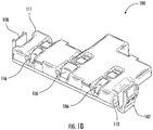
- Figure 1A illustrates a perspective view of the inner surface of an exemplary second housing component 100 comprising a top surface.
- the inner surface 103 may comprise a first sub-compartment 101 and a second sub-compartment 102, wherein the first sub-compartment 101 includes a first end wall 110, a second end wall 111, a first side wall 115, and a second side wall 116.
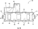
- Figure 1B illustrates a top view of the second housing component 100 illustrated in Figure 1A .
- the inner surface 103 further includes a plurality of crush ribs 105 located on the first and second side walls 115, 116.
- a plurality of crush ribs 105 are located on the inner surface of the first side wall 115 and a plurality of crush ribs 105 are located on inner surface of the second side wall 116.
- four crush ribs 105 are located on the inner surface of the first side wall 115 and four crush ribs 105 are located on the inner surface of the second side wall 116, as shown if Figures 1A and 1B .
- the crush ribs 105 are positioned at isolated points from one another along the length of the first side wall 115 and the second side wall 116.
- the distance between the crush ribs 105 on each of the side walls 115, 116 may or may not be equal.
- the number of crush ribs 105 located on the first side wall 115 may be equal to the number of crush ribs 105 located on the second side wall 116. In some embodiments, the number of crush ribs 105 located on the first side wall 115 is not equal to the number of crush ribs 105 located on the second side wall 116. In some embodiments, the crush rib(s) 105 located on the first side wall 115 may be paired and opposite to a crush rib(s) 105 located on the second side wall 116. In some embodiments, the crush rib(s) 105 located on the first side wall 115 is not paired in opposition with a crush rib(s) 105 located the second side wall 116. In an exemplary embodiment, each crush rib 105 located on the first side wall 115 is paired and directly opposite a corresponding crush rib 105 on the second side wall 116.
- the crush ribs 105 may be made from one or more flexible materials. In an exemplary embodiment, the crush ribs 105 are made from the same material as the second housing component. Alternatively, the crush ribs 105 may be formed from a different material that the second housing component 100. If the crush ribs 105 are made from the same material as the second housing component 100, the same mould may be used to form both. If the crush ribs 105 and the second housing component 100 are made from different materials, two-step moulding or other techniques commonly known to one of ordinary skill in the art may be used to form the second housing component 100 including crush ribs 105.
- the crush ribs 105 may be formed from a plastic material.
- the plastic material may be at least softer than the materials used to form the casing of a battery to be inserted into the battery holder assembly 400.
- An exemplary material used to form the crush ribs 105 is polypropylene.
- FIG. 1C illustrates an enlarged view of a crush rib 105 located on the inner surface of a side wall of the second housing component 100.
- Each crush rib includes a protrusion 120, which projects away from the side wall to which it is attached.
- each crush rib may also comprise a ribbing 121 located between the protrusion and the side wall, running at least the length of the protrusion.
- each crush rib 105 may extend from the inner top surface 103 of the second housing component 100, along the inner surface of the side wall 115, 116, and at its distal end, the crush rib 105 may terminate at or before the bottom surface of the side walls.
- the top face of this distal end is at an angle, which may or may not extend all the way to the bottom surface of the side walls. This angle allows the tip portion of the crush rib 105 to act as a lead-in, allowing it to more easily receive a flexible arm and have it slide along the surface of the protrusion 120.
- the protrusion 120 of the crush rib 105 is a triangular protrusion 120, as illustrated in Figure 1C .
- a crush rib 105 comprising a triangular protrusion 120 may readily deform and be "crushed” when a force is applied to it. This may allow for extra interference to be designed into the battery holder assembly by taking advantage of the flexible material that the crush rib 105 is made of. The extra interference provided by the crush rib 105 is from "crushing" by the force(s) being exerted upon it.
- the crush ribs 105 are attached to a vertical wall, they can take advantage of the nature of the vertical side walls 115, 116 to provide an opposing force back to the crush rib 105. If the vertical side walls 115, 116 are more stiff, this may allow for increased feedback or force to the crush ribs 105, and if the vertical side walls 115, 116 are more flexible, this may allow for them to flex as the "crushing" forces are applied to the crush ribs 105. This latter embodiment may allow for extra interference to be designed into the battery holder assembly with less reliance on the actual "crushing" of the crush ribs 105.
- the size of the triangular protrusion 120 may also vary and be adjusted to achieve a desired compression, or "crushing'. Varying the size of the protrusion 120 may allow for a desired interference to be achieved between the crush ribs 105 and the flexible arms 205. Having a particular sized protrusion 120 can also allow for optimum compensation to be achieved between the battery 235 and battery holder assembly 400 components. This may also minimize the effects on compensation as a result of variation in battery size.
- the crush rib's flexible protrusion may have a sharp edge, which could potentially dig into the vinyl jacket of a battery and exert a potentially damaging force on the battery. Having the flexible arm between the pointed, flexible protrusion of the crush rib 105 and the vinyl jacket of the battery 235 can prevent this particular damage from occurring to the battery 235.
- the protrusion 120 may comprise any other shaped protrusion that is compressible or crushable when a force is exerted upon it.
- Non-limiting examples of the shape include a rounded protrusion 120.
- the crush rib 105 does not "crush" in as much compared with a crush rib 105 having a triangular protrusion 120. Instead, it is the wall (the first or second side walls 115, 116 of the second housing component 100) which the crush rib 105 is aligned with and connected to that is pressed or flexed outwards.
- the amount of resistive force, or feedback, on the crush rib 105 could be better controlled in part by stiffening of the first and second side walls 115, 116.
- the size of the protrusion 120 of these alternatively shaped protrusions may vary as well.
- the top surface 103 of the second housing component 100 comprises ribs 106, configured to further secure the battery within a battery receptacle 202.
- each rib 106 extends from the inner surface of the first side wall 115 to the inner surface of the second side wall 116 across the top surface 103 of the second housing component 100.
- the shape of the ribs 106 may provide additional support for the battery following coupling of the second housing component 100 to the first housing component 200 comprising a battery.
- the surface of the ribs 106 preferably forms an arc on the inner surface of the second housing component 100.
- Other non-limiting embodiments of the shape of the ribs 106 are also possible and are determined in part by the shape of the battery residing in the battery receptacle 202.
- Figure 1D illustrates the location of the ribbing from the outer surface of the second housing component 100, wherein the ribs 106 are located at the areas of indent along the top surface 103 of the second housing component.
- the first sub-compartment 101 of the second housing component 100 may be positioned over a first housing component 200 to cover an opening in the first housing component 200 to a cavity 203 comprising a battery receptacle 202.
- the second housing component 100 comprises a second sub-compartment 102, which may be used to cover a separate portion of the first housing component, and may include at least a cavity for a battery plug 247 and clips for the battery cables 246 as illustrated in Figures 2A and 2B .
- the inner surface of the second sub-compartment 102 may be separated from the inner surface of the first sub-compartment 101 by at least the second side wall 116 of the first sub-compartment 101 as illustrated in Figures 1A and 1B .
- the second housing component 100 may further include flexible snaps 107, 108 located at the first and second end walls 110, 111 of the second housing component 100.
- the flexible snaps 107, 108 are made of flexible materials. Non-limiting examples may include materials such as polypropylene, nylon, and polycarbonate. In an exemplary embodiment, the flexible snaps 107, 108 may be made from the same material as the second housing component 100.
- the flexible snaps 107, 108 are configured to engage with hooks 220, 221, which are located on the first housing component 200.
- the first hook 220 is located on the first housing component 200 at a first end of the cavity and the second hook 221 is located on the first housing component 200 at a second end of the cavity.
- the first hook 220 and the second hook 221 are located exteriorly to the first flexible snap 107 and the second flexible snap 108, respectively, when the housing components 100, 200 are assembled.
- the first hook 220 exerts an inward force on the first flexible snap 107 towards a first end wall 110 of the second housing component 100
- the second hook 221 exerts an inward force on the second flexible snap 108 towards a second end wall 111 of the second housing component 100.
- the first and second flexible snaps 107, 108 are flexed in the same direction as the force being applied.
- the second housing component 100 may then be snapped into place within the first housing component 200, wherein the first hook 220 is fully engaged with the first flexible snap 107 and the second hook 221 is fully engaged with the second flexible snap 108.
- the first flexible snap 107 may exert an outward force on the first hook 220
- the second flexible snap 108 may exert an outward force on the second hook 221.
- the dynamic force of the flexible snaps 107, 108 helps to further secure the second housing component 100 with the first housing component 200.
- This configuration of the flexible snaps 107, 108 with the hooks 220, 221 also allow for the second housing component 100 to be removed without the need for specialized tools, so that the battery itself may be removed and replaced any number of times at any particular location or setting.
- Another potential advantage of this embodiment is that the flexible snaps 107, 108 may be moulded as part of the first housing component 200.
- alternate components commonly known in the art may be used in place of the flexible snaps 107, 108 and hooks 220, 221 for connecting the second housing component 100 with the first housing component 200.
- Non-limiting examples include the use of screws or clips.
- Figure 2A illustrates a top view of a first housing component 200 of the battery assembly module comprising an opening to a cavity 203 in which a battery receptacle 202 is located.
- the cavity 203 further comprises the first hook 220 and the second hook 221 as described in the foregoing.
- the cavity 203 is in part surrounded by a set of channels 216, 217 formed in part by a first outer side wall 212 and a second inner side wall 213, and a third inner side wall 214 and a fourth inner side wall 215 of the first housing component 200, respectively, and described in further detail below in Figures 5A - 5B .
- the battery receptacle 202 further comprises a base 207; a first side of the base 210; a second side of the base 211; a first tab 225 and a second tab 226 located at a first end and second end of the battery receptacle 202, respectively; and a plurality of flexible arms 205.
- the first tab 225 and the second tab 226 are configured to hold the ends of the battery within the battery receptacle 202 of the cavity.
- the tabs 225, 226 may be made from one or more flexible materials. Non-limiting examples may include materials such as polypropylene, nylon, and polycarbonate.
- the tabs 225, 226 may be formed from the same material as the first housing component 200.
- the crush ribs 105 may be formed from a different material that the second housing component 100. If the tabs 225, 226 are made from the same material as the first housing component 200, the same mould may be used to form both. If the tabs 225, 226 and the first housing component 200 are formed from different materials, two-step moulding or other techniques commonly known to one of ordinary skill in the art may be used to form the first housing component 200 including tabs 225, 226.
- Each of the tabs 225, 226 is flexible and compressible. During placement of the battery 235 into the battery receptacle 202 and once in place, the battery 235 may exert a force on the tabs 225, 226, at least partially pressing them outward, towards each end of the cavity, respectively. The tabs 225, 226 may also exert an opposing force back on the battery to help secure the battery within the battery receptacle 202.
- the flexible arms 205 are shaped and configured to receive and support a battery within the battery receptacle 202 of the first housing component 200.
- the flexible arms 205 may be made from one or more flexible materials. Non-limiting examples may include materials such as polypropylene, nylon, and polycarbonate.
- the flexible arms 205 may be formed from the same material as the first housing component 200. Alternatively, the flexible arms 205 may be formed from a different material than the first housing component 200. If the flexible arms 205 are made from the same material as the first housing component 200, the same mould may be used to form both. If the flexible arms 205 and the first housing component 200 are formed from different materials, two-step moulding or other techniques commonly known to one of ordinary skill in the art may be used to form the first housing component 200 including flexible arms 205.
- Each flexible arm of the plurality of flexible arms extends from the base 207 of the battery receptacle 202 towards the opening of the cavity in the first housing component 200.
- at least one flexible arm 205 extends from a first side of the base 210 and at least one extends from a second side of the base 211.
- a plurality of flexible arms 205 extend from a first side of the base 210 and a plurality of flexible arms 205 extend from a second side of the base 211.
- at least two flexible arms 205 extend from a first side of the base 210 and at least two flexible arms 205 extend from a second side of the base 211.
- the flexible arms 205 are positioned at isolated points from one another along the length of the first side of the base 210 and along the length of the second side of the base 211.
- the distance between the flexible arms 205 along the first and second sides of the base 210, 211 may be equal. In another embodiment, the distance between the flexible arms 205 along the first and second sides of the base 210, 211 is not equal.
- the number of flexible arms 205 extending from the first side of the base 210 may or may not be equal to the number of flexible arms 205 extending from the second side of the base 211.
- the flexible arm(s) 205 located on the first side of the base 210 may be paired with and opposite to a flexible arm(s) 105 located on the second side of the base 211.
- the flexible arm(s) 205 located on the first side of the base 210 are not paired in opposition with a flexible arm(s) 205 located the second side of the base 211.
- the flexible arms 205 flex a relative amount to allow a battery to snap into place within the battery receptacle 202. In an embodiment, once the flexible arms 205 snap around the battery 235, a portion of the flexible arms 205 follows the circumference of the battery 235. In another embodiment, whereby the battery 235 is not cylindrical, the flexible arms 205 snap around the battery 235 and a portion of the flexible arms 205 follows or contacts at least a portion of the outer surface of the battery 235.
- the first housing component may further comprise a plurality of connectors 230 for mounting the assembled battery holder assembly to a device in need of the battery holder assembly 400.
- the battery housing assembly 400 may also be mounted to a device in need of the battery holder assembly 400 by any means commonly known in the art, including but not limited to clips, snaps, and screws.
- a connector 230 may be located at each corner end of the end walls of the first housing component 200 as illustrated in Figures 2A-2C . In another embodiment, the connectors 230 may be located at each corner end of the side walls of the first housing component 200. In another embodiment the connectors 230 may be located along the side walls or end walls of the first housing component 200. In an embodiment there could be two or more connectors 230. In an exemplary embodiment, there are four connectors 230.
- the first housing component 200 may further comprise a battery plug cavity 247, wherein a battery plug 245 is housed as illustrated in Figure 2B .
- the first housing component 200 may also comprise clips 246 on its surface wherein battery cables for a charging circuit of a battery may be held.
- Figure 3A illustrates the bottom surface of the first housing component 200, wherein other components may be positioned.
- Non-limiting examples of these components may include, at least one of a printed circuit board, an amplifier, a microphone, or a speaker. These components can be arranged within the first housing component in any arrangement suitable for use.
- Figure 3B illustrates an outer view of an end cap 300 component of the battery holder assembly 400.
- the end cap 300 is configured to cover at least a bottom surface of the first housing component 200.
- the end cap 300 may be considered as the main cover for the entire battery holder assembly module 400 and can be coupled to the first housing component 200 using any means commonly known in the art by one of ordinary skill, including receiving hooks 307, which can be coupled to side hooks 206 on the first housing component 200.
- the end cap 300 may be made from one or more materials. Non-limiting examples may include materials such as plastic, aluminum, and stamped steel.
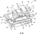
- FIG 4A illustrates the battery holder assembly 400, having a battery 235 has been placed within the first housing component 200, wherein the second housing component 100 is positioned above, and not coupled to the first housing component 200.
- the battery 235 is positioned within the battery receptacle 202 and the flexible arms have flexed around the battery and at least a portion of the flexible arm 205 follows the circumference of the battery 235.
- Figure 4A also illustrates the second housing component 100 from its outer surface, which is positioned for alignment and coupling onto the first housing component 200.
- the first flexible snap 107 is aligned with the first hook 220 and the second flexible snap 108 is aligned with the second hook 221.
- the crush ribs 105 are located on the inner surface of the second housing component 100, but once in position, the crush ribs 105 may also contact the flexible arms 205 of the first housing component 200 to help align the first housing component 200 with the second housing component 100.
- the cables from the battery 235 have not been included in order to better visualize the components of the battery holder assembly module.
- the end cap 300 is positioned on the bottom surface of the first housing component 200, wherein the first housing component 200 may further comprise side hooks 206 for coupling with the end cap 300.
- a side hook 206 is located at each corner end of the side walls of the first housing component 200 as illustrated in Figures 4A and 4B .
- the side hooks 206 may be located along the end walls of the first housing component 200 provided they are not in the way of the connectors' 230 ability to connect to a vehicle.
- the side hooks 206 may be located on side walls and end walls of the first housing component 200, at or not at the corner edge. In an embodiment there could be two or more side hooks 206.
- the end cap 300 may be coupled to the first housing component 200 using any means commonly known in the art by one of ordinary skill, including receiving hooks 307, which can be coupled to side hooks 206 on the first housing component 200.
- Figure 4B illustrates the battery holder assembly 400, wherein the second housing component 100 is coupled with the first housing component 200.
- the first flexible snap 107 is engaged with the first hook 220 of the first housing component and the second flexible snap 108 is engaged with the second hook 221 of the first housing component 200.
- Not shown are at least the crush ribs 105 because they are located on the inner surface of the second housing component 100; however, the crush ribs 105 are engaged with the flexible arms 205 of the first housing component 200.
- the first sub-compartment 101 of the second housing component 100 is positioned above the cavity comprising the battery 235 and battery receptacle 202, and a second sub-compartment 102 is positioned above the clips for cables 246 and the battery plug cavity 247, wherein a battery plug 245 may be housed.
- Figure 5A illustrates a cross-sectional view of the assembled battery holder assembly 400 having a battery 235 in place. Illustrated are at least the end cap 300; the first housing component 200; the base 207 and flexible arms 205 of the battery receptacle 202; and the second housing component 100 comprising the crush ribs 105.
- a channel follows the perimeter of the cavity 203, surrounding it.
- the channel may be defined at least by a first channel part 216 on one side of the cavity 203 and a second channel part 217 on a second side of the cavity 203.
- the channel is formed at least by an outer wall and a series of inner walls of the first housing component 200.
- the first channel part 216 may be formed by a first outer side wall 212 and a second inner side wall 213, and the second channel part 217 may be formed by a third inner side wall 214 and a fourth inner side wall 215.
- first channel part 216 and the second channel part 217 can be brought into contact with the first side wall 115 and second side wall 116 of the second housing component, respectively, helping to align the first housing component 200 with the second housing component 100.
- first side wall 115 and the second side wall 116 of the first housing component 200 may be inserted into the first channel part 216 and the second channel part 217 of the second housing component 100, respectively, upon coupling of the first and second housing components 200, 100.
- first side wall 115 of the second housing component 100 extends to the bottom of the first channel part 216 and the second side wall 116 of the second housing component 100 extends to the bottom of the second channel part 217.
- the battery holder assembly in its final setting is oriented such that the first housing component 200 is on top of the second housing component 100. Accordingly, the first and second channel parts 216, 217 would be on top and may act as an umbrella to prevent water or liquids from splashing into the battery receptacle and reaching the battery 235.
- an O-ring or sealant may be placed in the channel to provide a waterproof seal. This could be useful in either orientation, whether the first housing component 200 is on top of or under the second housing component 100.
- Figure 5B illustrates an enlarged cross-sectional view of the assembled battery holder assembly 400 having a battery 235 in place.
- the crush ribs 105 have a triangular protrusion 120.
- the pointed tips of the triangular protrusion of each crush rib 105 do not directly press against the battery 235.
- FIG. 5B Also illustrated in Figure 5B is a "crushing" of a portion of the protrusion 120 of the crush ribs 105.
- the outward force applied by the flexible arms 205 "crushes" the portion of the protrusion 120 that is in contact with it.
- the crush ribs 105 can in turn exert a force back against the flexible arms 205, wherein the flexible arms 205 spread out the force being applied. This compressive interaction between the crush ribs 105 and the flexible arms 205 helps to keep a tight yet flexible connection between the second housing component 100, the first housing component 200, and the battery 235.
- the battery 235 may be cylindrical, as illustrated in Figures 2B , 4A , 4B , and 5A - 5B .
- the battery is an 18650 rechargeable battery.
- a charging circuit is present in the battery holder assembly 400 so that the battery 235 is always being charged.
- different shapes and types of batteries may be used in the battery holder assembly 400 and may include at least a battery pact.
- the entire battery holder assembly 400 may be turned upside down so that the second housing component 100 is on the top and the first housing component 200 is on the bottom of the assembly 400.
- all reference points correspond with the orientations illustrated in the drawings.
- the first housing component 200 is a housing and the second housing component 100 is a battery cover.
- the first housing component may be the battery cover and the second housing component may be the housing.
- This disclosure also represents a method 600 for securing a battery 235 within the battery holder assembly 400 disclosed in the foregoing.
- the steps can be re-arranged or omitted.
- a battery 235 may be placed 601 into a battery receptacle 202, which is located within the cavity 203 of a first housing component 200 of the battery holder assembly 400. Once in position, pressing 602 of the battery 235 into the battery receptacle 202 comprising the flexible arms 205 occurs. During this pressing 602, the flexible arms 205 flex 603 outward to receive the battery 235. Flexible arms 205 located along a first side of the base 210 may flex out towards a first outer side wall 212 of the cavity 203, and flexible arms 205 located along a second side of the base 211 may flex out towards a third inner side wall 214 of the cavity 203.
- the battery 235 may then be fully pressed into place within the battery receptacle 202, wherein the flexible arms 205 may follow an outer surface of the battery. Once in position, the flexible arms 205 may exert an opposing force on the battery 235, helping to secure the battery 235 within the battery receptacle 202.
- the ends of the battery 235 may also contact a first tab 225 and second tab 226 of the battery receptacle 202, wherein the first tab 225 is located at a first end of the base and second tab 226 is located at a second end of the base.
- the respective ends of the battery 235 exert a force on the first tab 225 and second tab 226, flexing 604 the first and second tabs 225, 226 in opposing directions. This flexing of the tabs 604 may allow the battery 235 to be further pressed into position.
- the battery 235 When a sufficient amount of force is applied, the battery 235 may then be fully pressed into position within the battery receptacle 202. Once in position, the flexible tabs 225, 226 may exert an opposing force on the battery 235, helping to secure the battery 235 within the battery receptacle 202.
- flexing of the flexible arms 603, and flexing of the first and second tabs 604 may occur simultaneously until the battery 235 is fully positioned in the battery receptacle 202 along the base 207. Pressing 602 of the battery 235 into position occurs in each embodiment; however, in some embodiment, flexing 603 of the flexible arms 603 may occur alone or in combination with flexing 604 of the flexible tabs 225, 226.
- a second housing component 100 is aligned with the first housing component 200. Aligning 605 of the second housing component 100 with the first housing component 200 may occur prior to or after contact between the housing components 100, 200. Aligning may comprise aligning 606 of the plurality of crush ribs 105 with the plurality of flexible arms 205; aligning 607 of a first side wall 115 and second side wall 116 of the second housing component 100 with a first channel part 216 and second channel part 217 of the first housing component 200, respectively; and aligning 608 of a first flexible snap 107 and second flexible snap 108 of the second housing component 100 with a first hook 220 and a second hook 221 of the first housing component 200, respectively.
- a distal tip portion of the plurality of flexible arms 205 is aligned 606 with the distal end of a corresponding crush rib 105 of the plurality of crush ribs 105.
- the distal end of each flexible arm 205 may contact the top face of the distal end portion of a corresponding crush rib 105.
- Each of these steps including the aligning 606 of the plurality of crush ribs 105 with the plurality of flexible arms 205, the aligning of the first and second side walls 115, 116 of the second housing component 100 with the first and second channel parts 216, 217 of the first housing component 200, and the aligning 608 of the first and second hook 220, 221 with the first and second flexible snaps 107, 108, may occur simultaneously until the housing components 100, 200 are coupled.
- Each of these aligning steps 606, 607, and 608 may be used alone or in combination with the other aligning steps disclosed herein.
- Coupling may comprise sliding 610 of the plurality of flexible arms along a protrusion of each corresponding crush rib; and coupling 611 of the first flexible snap 107 and second flexible snap 108 of the second housing component 100 with a first hook 220 and a second hook 221 of the first housing component 200, respectively.
- sliding 610 of an outer surface of the plurality of flexible arms 205 along the protrusion 120 of a corresponding crush rib 105 exerts a force on the protrusion, "crushing" the portion of the protrusion 120 that the flexible arm 205 is in contact with.
- the distal end of the crush rib 105 has a top face that is angled as shown in Figure 1C . This angle is configured to allow the tip portion of the crush rib 105 to act as a lead-in, allowing it to more easily receive the flexible arm and have it slide 610 along the surface of its protrusion 120.
- each protrusion 120 of the crush ribs 105 is less "crushable”
- the flexible arms 205 slide 610 along the protrusion 120 of the crush ribs 105 and exert a force on the crush ribs 105; however, that force is at least directed relatively more to flexing the first and second side walls 115, 116 of the second housing component 100 away from the flexible arms 205.
- each protrusion 120 of the crush ribs 105 is more "crushable”
- the flexible arms 205 slide 610 along the protrusion 120 of the crush ribs 105 and exert a force on the crush ribs 105; however, that force is directed relatively more to "crushing” the crush ribs 105 than in the case of the crush ribs 105 that are less “crushable.”
- the degree of flexing of the first and second side walls 115, 116 may be affected inversely by the degree of "crushing" by the crush rubs 105.
- the flexible arms 205 slide 610 along the crush ribs 105, the flexible arms 205 exert a force on the protrusion 120 of the crush ribs 105, partially crushing the protrusion 120, and partially flexing the first and second side walls 115, 116 of the second housing component 100 away from the flexible arms 205.
- both the protrusions 120 "crush" and the first and second side walls 115, 116 of the second housing component 100 flex outward.
- coupling of the first hook 220 and the second hook 221 of the first housing component 200 with the first flexible snap 107 and second flexible snap 108 of the second housing component 100, respectively, further couples the first housing component 200 with the second housing component 100.
- a first flexible snap 107 of the second housing component 100 is configured to engage a first hook 220 of the first housing component 200 and a second flexible snap 108 of the second housing component 100 is configured to engage a second hook 221 of the first housing component 200.
- first hook 220 and the second hook 221 are located exteriorly to the first flexible snap 107 and the second flexible snap 108 in the assembled state.
- first hook 220 exerts an inward force on the first flexible snap 107 towards a first end wall 110 of the second housing component 100
- second hook 221 exerts an inward force on the second flexible snap 108 towards a second end wall 111 of the second housing component 100.
- coupling 611 may be done by any alternate method commonly known in the art for connecting two components, in place of the flexible snaps 107, 108 and hooks 220, 221 described herein.
- Non-limiting examples of coupling means include screws or clips.
- first and second flexible snaps 220, 221 may be further pressed towards the end walls of the 110, 111 of the second housing component 100, by a user, to facilitate disengagement of the second housing component 100 from the first housing component 200.
- the force used to press the flexible snaps 107, 108 towards the end walls 110, 111 is great enough, the flexible snaps 107, 108 may be disengaged from their respective hooks 220, 221, and the second housing component 100 may be uncoupled from first housing component 200.
- an end cap 300 may be coupled to the first housing component 200, covering at least a portion of the bottom surface of the first housing component 200, opposite the opening to the battery receptacle 202.
- coupling of the end cap 300 may comprise placing the end cap 300 over the bottom surface of the first housing component 200 when the second housing component 100 is not coupled with the first housing component 200.
- coupling of the end cap 300 may comprise placing the end cap 300 over the bottom surface of the first housing component when the second housing component 100 is coupled with the first housing component 200. Coupling may be done using any means commonly known in the art by one of ordinary skill.
- a non-limiting example includes the receiving hooks 307, which are configured to be coupled with the side hooks 206 on the first housing component 200.
Landscapes
- Chemical & Material Sciences (AREA)
- Chemical Kinetics & Catalysis (AREA)
- Electrochemistry (AREA)
- General Chemical & Material Sciences (AREA)
- Engineering & Computer Science (AREA)
- Aviation & Aerospace Engineering (AREA)
- Battery Mounting, Suspending (AREA)
Claims (15)
- Batteriehalterbaugruppe (400), eine erste Gehäusekomponente (200), eine zweite Gehäusekomponente (100), und eine Batterieaufnahme (202) umfassend, wobei die erste Gehäusekomponente (200) die Batterieaufnahme (202) umfasst,
die Batterieaufnahme (202) eine Vielzahl von flexiblen Armen (205) umfasst, die die Batterie stützen,
die zweite Gehäusekomponente (100) eine Vielzahl von Quetschrippen (105) umfasst, und
die erste Gehäusekomponente (200) an die zweite Gehäusekomponente (100) gekoppelt ist,
wobei die Quetschrippen (105) durch die flexiblen Arme (205) gequetscht werden, wenn die erste Gehäusekomponente (200) und die zweite Gehäusekomponente (100) gekoppelt sind. - Batteriehalterbaugruppe (400) nach Anspruch 1, wobei die erste Gehäusekomponente (200) ein Gehäuse und die zweite Gehäusekomponente (100) eine Abdeckung ist, oder die erste Gehäusekomponente (200) die Abdeckung und die zweite Gehäusekomponente (100) das Gehäuse ist.
- Batteriehalterbaugruppe (400) nach Anspruch 1, wobei:sich die Vielzahl von flexiblen Armen (205) von einer Basis der Batterieaufnahme (202) erstreckt, und sich mindestens ein flexibler Arm (205) von der Vielzahl von flexiblen Armen (205) von einer ersten Seite (210) der Basis und mindestens einer von den flexiblen Armen (205) von der Vielzahl von flexiblen Armen (205) von einer zweiten Seite (211) der Basis erstreckt; odersich die Vielzahl von Quetschrippen (105) von einer inneren Oberfläche (103) der zweiten Gehäusekomponente (100) erstreckt, undmindestens eine Quetschrippe (105) an den mindestens einen flexiblen Arm koppelbar ist, der sich von der ersten Seite (210) der Basis erstreckt und mindestens eine Quetschrippe (105) an den mindestens einen flexiblen Arm (205) koppelbar ist, der sich von der zweiten Seite (211) der Basis erstreckt.
- Batteriehalterbaugruppe (400) nach Anspruch 1, wobei jede Quetschrippe (105) einen Vorsprung (120) umfasst.
- Batteriehalterbaugruppe (400) nach Anspruch 4, wobei der Vorsprung (120) dreieckig oder gerundet ist.
- Batteriehalterbaugruppe (400) nach Anspruch 1, wobei jede Quetschrippe (105) von der Vielzahl von Quetschrippen (105) ferner eine Riffelung (121) umfasst.
- Batteriehalterbaugruppe (400) nach Anspruch 1, wobei die erste Gehäusekomponente (200) ferner einen ersten Haken (220) und einen zweiten Haken (221) umfasst, and die zweite Gehäusekomponente (100) ferner ein erstes flexibles Schnappelement (107) und ein zweites flexibles Schnappelement (108) umfasst, und das erste flexible Schnappelement (107) den ersten Haken (220) empfängt und das zweite flexible Schnappelement (108) den zweiten Haken (221) empfängt, nachdem die erste Gehäusekomponente (200) mit der zweiten Gehäusekomponente (100) gekoppelt ist; oder
die erste Gehäusekomponente (200) ferner eine erste Nase (225), die an einem ersten Ende der Basis der Batterieaufnahme (202) angeordnet ist, und eine zweite Nase (226) umfasst, die an einem zweiten Ende der Basis der Batterieaufnahme (202) angeordnet ist, und die erste Nase (225) und die zweite Nase (226) dazu konfiguriert sind, die Batterie in der Batterieaufnahme (202) zu sichern. - Batteriehalterbaugruppe (400) nach Anspruch 1, wobei die erste Gehäusekomponente (200) einen Teil eines ersten Kanals (216) und einen Teil eines zweiten Kanals (217) umfasst, wobei
der Teil des ersten Kanals (216) zwischen einer ersten äußeren Seitenwand (212) und einer zweiten inneren Seitenwand (213) der ersten Gehäusekomponente (200) gebildet ist, und
der Teil des zweiten Kanals (217) zwischen einer dritten inneren Seitenwand (214) und einer vierten inneren Seitenwand (215) der ersten Gehäusekomponente (200) gebildet ist, und
eine erste Seitenwand (115) der zweiten Gehäusekomponente (100) in den Teil des ersten Kanals (216) hineinragt und eine zweite Seitenwand (116) der zweiten Gehäusekomponente (100) in den Teil des zweiten Kanals (217) hineinragt. - Batteriehalterbaugruppe (400) nach Anspruch 1, ferner eine Endkappe umfassend, die dazu konfiguriert ist, mindestens einen Abschnitt einer äußeren Oberfläche der ersten Gehäusekomponente (200) abzudecken; oder
die Batteriehalterbaugruppe nach Anspruch 1, wobei die erste Gehäusekomponente (200) ferner eine Vielzahl von Verbindungselementen umfasst, um die Batteriehalterbaugruppe mit einem Fahrzeug oder einer anderen Vorrichtung zu verbinden. - Batteriehalterbaugruppe (400) nach Anspruch 1, wobei die zweite Gehäusekomponente (100) ferner mindestens eine Rippe (106) umfasst, wobei
sich die Rippe (106) über eine obere innere Oberfläche (103) der zweiten Gehäusekomponente (100) von der ersten Seitenwand (115) zu der zweiten Seitenwand (116) erstreckt, und
die Rippe (106) von der inneren Oberfläche (103) der zweiten Gehäusekomponente (100) in einer Form vorspringt, die dazu konfiguriert ist, die Batterie innerhalb der Batterieaufnahme (202) zu bewahren, wenn die zweite Gehäusekomponente (100) an die erste Gehäusekomponente (200) gekoppelt ist. - Verfahren zum Sichern einer Batterie innerhalb einer Batteriehalterbaugruppe (400), eine erste Gehäusekomponente (200) und eine zweite Gehäusekomponente (100) umfassend, wobei das Verfahren Folgendes umfasst:Platzieren der Batterie in einer Batterieaufnahme (202) der ersten Gehäusekomponente (200), wobei die Batterieaufnahme (202) eine erste Vielzahl von flexiblen Armen (205) umfasst, die sich von einer Basis der Batterieaufnahme (202) erstrecken und sich biegen, um die Batterie aufzunehmen, und sich mindestens ein erster flexibler Arm (205) von der Vielzahl von flexiblen Armen (205) von einer ersten Seite (210) der Basis erstreckt und sich mindestens ein zweiter flexibler Arm (205) von der Vielzahl von flexiblen Armen (205) von einer zweiten Seite (211) der Basis erstreckt;Ausrichten einer zweiten Gehäusekomponente (100), die eine Vielzahl von Quetschrippen (105) auf einer inneren Oberfläche (103) umfasst, mit der ersten Gehäusekomponente (200), wobei die Vielzahl von Quetschrippen (105) einen entsprechenden flexiblen Arm (205) von der Vielzahl von flexiblen Armen (205) berührt; undKoppeln der ersten Gehäusekomponente (200) mit der zweiten Gehäusekomponente (100), wobei nach dem Koppeln:
sich mindestens ein flexibler Arm (205) von der Vielzahl von flexiblen Armen (205) an einem Vorsprung (120) einer entsprechenden Quetschrippe (105) von der Vielzahl von Quetschrippen (105) entlang bewegt, die mindestens einen Abschnitt von dem Vorsprung (120) von jeder entsprechenden Quetschrippe (105) quetschen, die mit dem flexiblen Arm (205) in Berührung steht. - Verfahren zum Sichern einer Batterie innerhalb der Batteriehalterbaugruppe (400) nach Anspruch 11, wobei das Platzieren der Batterie innerhalb der Batterieaufnahme (202) ferner ein Platzieren der Batterie zwischen einer ersten Nase (225), die sich an einem ersten Ende der Basis der Batterieaufnahme (202) befindet, und einer zweiten Nase (227), die sich an einem zweiten Ende der Basis der Batterieaufnahme (202) befindet, wobei
sich die erste Nase (225) und die zweite Nase (226) in entgegengesetzte Richtungen biegen, um die Batterie aufzunehmen, und sich zueinander hin biegen, um die Batterie in der Batterieaufnahme (202) zu sichern. - Verfahren zum Sichern einer Batterie innerhalb der Batteriehalterbaugruppe (400) nach Anspruch 11, wobei das Ausrichten ferner ein Ausrichten von Folgendem umfasst:einer ersten Seitenwand (115) der zweiten Gehäusekomponente (100) mit einem Teil eines ersten Kanals (216), der zwischen einer ersten äußeren Seitenwand (212) der ersten Gehäusekomponente (200) und einer zweiten inneren Wand (213) der ersten Gehäusekomponente (200) gebildet ist; undeiner zweiten Seitenwand (116) der zweiten Gehäusekomponente (100) mit einem Teil eines zweiten Kanals (217), der zwischen einer dritten inneren Seitenwand (214) der ersten Gehäusekomponente (200) und einer vierten inneren Seitenwand (215) der ersten Gehäusekomponente (200) gebildet ist, wobeidie erste Seitenwand (115) in den Teil des ersten Kanals (216) hineinragt, unddie zweite Seitenwand (116) in den Teil des zweiten Kanals (217) hineinragt.
- Verfahren zum Sichern einer Batterie innerhalb der Batteriehalterbaugruppe (400) nach Anspruch 11, wobei das Ausrichten ferner ein Ausrichten eines ersten Hakens (220) mit einem ersten flexiblen Schnappelement (107) und eines zweiten Hakens (221) mit einem zweiten flexiblen Schnappelement (108) umfasst, wobei die erste Gehäusekomponente (200) den ersten Haken (220) und den zweiten Haken (221) umfasst, und die zweite Gehäusekomponente (100) das erste flexible Schnappelement (107), das an einer ersten Endwand der zweiten Gehäusekomponente (100) angeordnet ist, und das zweite flexible Schnappelement (108), das an einer zweiten Endwand der zweiten Gehäusekomponente (100) angeordnet ist, umfasst; oder
wobei das Koppeln ferner ein Koppeln des ersten Hakens (220) mit dem ersten flexiblen Schnappelement und des zweiten Hakens (221) mit dem zweiten flexiblen Schnappelement umfasst. - Verfahren zum Sichern einer Batterie innerhalb der Batteriehalterbaugruppe (400) nach Anspruch 11, wobei die Vielzahl von Quetschrippen (105) nach dem Koppeln eine entgegengesetzte Kraft auf den entsprechenden flexiblen Arm (205) von der Vielzahl von flexiblen Armen (205) ausübt, wobei jeder flexible Arm (205) gegen die Batterie drückt.
Applications Claiming Priority (3)
| Application Number | Priority Date | Filing Date | Title |
|---|---|---|---|
| US201662377319P | 2016-08-19 | 2016-08-19 | |
| US15/681,004 US11050113B2 (en) | 2016-08-19 | 2017-08-18 | Battery holder |
| PCT/US2017/047838 WO2018035532A1 (en) | 2016-08-19 | 2017-08-21 | Battery holder |
Publications (2)
| Publication Number | Publication Date |
|---|---|
| EP3485523A1 EP3485523A1 (de) | 2019-05-22 |
| EP3485523B1 true EP3485523B1 (de) | 2020-06-10 |
Family
ID=61192167
Family Applications (1)
| Application Number | Title | Priority Date | Filing Date |
|---|---|---|---|
| EP17764479.6A Active EP3485523B1 (de) | 2016-08-19 | 2017-08-21 | Batteriehalter |
Country Status (6)
| Country | Link |
|---|---|
| US (1) | US11050113B2 (de) |
| EP (1) | EP3485523B1 (de) |
| JP (1) | JP6903122B2 (de) |
| KR (1) | KR102189212B1 (de) |
| CN (1) | CN109844987B (de) |
| WO (1) | WO2018035532A1 (de) |
Cited By (1)
| Publication number | Priority date | Publication date | Assignee | Title |
|---|---|---|---|---|
| EP4576369A1 (de) * | 2023-12-21 | 2025-06-25 | Sungrow Power Supply Co., Ltd. | Gehäuse und zellenmodul damit |
Families Citing this family (8)
| Publication number | Priority date | Publication date | Assignee | Title |
|---|---|---|---|---|
| KR102066198B1 (ko) * | 2017-07-13 | 2020-01-14 | 주식회사 엘지화학 | 배터리 팩 |
| KR102366507B1 (ko) | 2018-06-26 | 2022-02-22 | 주식회사 엘지에너지솔루션 | 배터리 팩 및 이를 포함하는 자동차 |
| US11890705B2 (en) * | 2018-11-13 | 2024-02-06 | Rivian Ip Holdings, Llc | Weld location detection in a battery cell pack |
| TWI688853B (zh) * | 2018-12-13 | 2020-03-21 | 英業達股份有限公司 | 電池固定結構 |
| JP7199303B2 (ja) * | 2019-05-17 | 2023-01-05 | 株式会社東芝 | 電池モジュール、電池パック及び車両 |
| US11394092B1 (en) * | 2021-05-13 | 2022-07-19 | Beta Air, Llc | Crash safe battery pack for mediating risks of electrical short circuits during impact |
| US20240313320A1 (en) * | 2023-03-14 | 2024-09-19 | Geotab Inc. | Electronic device housing with integrated battery compartment |
| CN118593127B (zh) * | 2024-07-08 | 2025-11-28 | 天津大学医疗机器人与智能系统研究院 | 用于双目视觉系统的支撑装置、双目视觉系统及光学定位系统 |
Family Cites Families (16)
| Publication number | Priority date | Publication date | Assignee | Title |
|---|---|---|---|---|
| JPS4934314A (de) | 1972-06-12 | 1974-03-29 | ||
| JPS5240010Y2 (de) * | 1972-06-28 | 1977-09-10 | ||
| US4885219A (en) * | 1988-11-21 | 1989-12-05 | American Telephone And Telegraph Company | Rotatable storage compartment for batteries and the like |
| KR970005788Y1 (ko) * | 1991-06-28 | 1997-06-13 | 기아자동차 주식회사 | 오일팬의 드레인 플러그 소켓구조 |
| JP3485719B2 (ja) | 1996-04-26 | 2004-01-13 | 三洋電機株式会社 | 方向性なく装着できるパック電池 |
| US7556882B2 (en) * | 2004-08-20 | 2009-07-07 | Honeywell International Inc. | Impact resistant battery housing with cover |
| JP5109295B2 (ja) * | 2006-06-28 | 2012-12-26 | カシオ計算機株式会社 | 電池蓋の取付構造 |
| JP2008258110A (ja) | 2007-04-09 | 2008-10-23 | Matsushita Electric Ind Co Ltd | 電池パック |
| JP5046885B2 (ja) | 2007-11-26 | 2012-10-10 | 三洋電機株式会社 | 携帯式電源 |
| JP5465440B2 (ja) * | 2009-01-28 | 2014-04-09 | 三洋電機株式会社 | 組電池 |
| KR101084836B1 (ko) * | 2009-10-27 | 2011-11-21 | 삼성에스디아이 주식회사 | 배터리 팩 |
| EP2500961B1 (de) | 2011-03-15 | 2017-07-26 | Johnson Controls Automotive Electronics GmbH | Gehäuseanordnung für einen elektrischen Energiespeicher |
| JP5648621B2 (ja) | 2011-11-14 | 2015-01-07 | 株式会社デンソー | 組電池 |
| JP6246483B2 (ja) | 2013-04-04 | 2017-12-13 | 株式会社マキタ | 電動工具用電池パック |
| US9525195B2 (en) * | 2013-07-30 | 2016-12-20 | Johnson Controls Technology Corporation | Remanufacturing methods for battery module |
| US9331315B1 (en) | 2013-09-30 | 2016-05-03 | Amazon Technologies, Inc. | Solderless battery contact |
-
2017
- 2017-08-18 US US15/681,004 patent/US11050113B2/en not_active Expired - Fee Related
- 2017-08-21 WO PCT/US2017/047838 patent/WO2018035532A1/en not_active Ceased
- 2017-08-21 CN CN201780063082.6A patent/CN109844987B/zh not_active Expired - Fee Related
- 2017-08-21 EP EP17764479.6A patent/EP3485523B1/de active Active
- 2017-08-21 KR KR1020197007980A patent/KR102189212B1/ko not_active Expired - Fee Related
- 2017-08-21 JP JP2019509476A patent/JP6903122B2/ja not_active Expired - Fee Related
Non-Patent Citations (1)
| Title |
|---|
| None * |
Cited By (1)
| Publication number | Priority date | Publication date | Assignee | Title |
|---|---|---|---|---|
| EP4576369A1 (de) * | 2023-12-21 | 2025-06-25 | Sungrow Power Supply Co., Ltd. | Gehäuse und zellenmodul damit |
Also Published As
| Publication number | Publication date |
|---|---|
| EP3485523A1 (de) | 2019-05-22 |
| JP2019530136A (ja) | 2019-10-17 |
| KR102189212B1 (ko) | 2020-12-10 |
| WO2018035532A1 (en) | 2018-02-22 |
| US20180053922A1 (en) | 2018-02-22 |
| JP6903122B2 (ja) | 2021-07-14 |
| KR20190040280A (ko) | 2019-04-17 |
| CN109844987B (zh) | 2021-12-14 |
| CN109844987A (zh) | 2019-06-04 |
| US11050113B2 (en) | 2021-06-29 |
Similar Documents
| Publication | Publication Date | Title |
|---|---|---|
| EP3485523B1 (de) | Batteriehalter | |
| EP2390943B1 (de) | Batteriegehäusevorrichtung | |
| CN103443887B (zh) | 电容器组件 | |
| JP5796952B2 (ja) | コネクタと筺体との防水構造 | |
| US9627807B2 (en) | Remote radio unit, and cable connector assembly and housing of the same | |
| US20190273229A1 (en) | Top loading battery holder | |
| US7220137B1 (en) | Cover for multiplex receptacle set | |
| JP6858236B2 (ja) | 高圧コネクタ及び電池製品 | |
| JP2021501965A (ja) | 拡張型コネクタ組立体 | |
| US11978976B2 (en) | Removable cable connector | |
| WO2010022142A1 (en) | Battery retainer | |
| KR20220158005A (ko) | 벽에서 케이블의 접합부를 밀봉하기 위한 조립체 | |
| CN210430954U (zh) | 一种耳机盒 | |
| US8508931B2 (en) | Recorder set and holder | |
| RU173396U1 (ru) | Защитная крышка для встраиваемых в стену устройств | |
| CN222073375U (zh) | 一种电子设备及一种耳机 | |
| EP3605743B1 (de) | Verbinder | |
| US6719584B1 (en) | Watertight flexible connector | |
| US9985386B1 (en) | Junction box assembly with internal power connecting feature | |
| CN209963132U (zh) | 一种低阻抗电池盒 | |
| US20260129343A1 (en) | Electronic devices and earphones | |
| KR102550201B1 (ko) | 커넥터 | |
| CN214413193U (zh) | 一种遥控盒及电器 | |
| EP1100162B1 (de) | Anordnung zur Befestigung eines Steckers und ein Stecker | |
| EP4694193A1 (de) | Elektronische vorrichtung und ohrhörer |
Legal Events
| Date | Code | Title | Description |
|---|---|---|---|
| STAA | Information on the status of an ep patent application or granted ep patent |
Free format text: STATUS: UNKNOWN |
|
| STAA | Information on the status of an ep patent application or granted ep patent |
Free format text: STATUS: THE INTERNATIONAL PUBLICATION HAS BEEN MADE |
|
| PUAI | Public reference made under article 153(3) epc to a published international application that has entered the european phase |
Free format text: ORIGINAL CODE: 0009012 |
|
| STAA | Information on the status of an ep patent application or granted ep patent |
Free format text: STATUS: REQUEST FOR EXAMINATION WAS MADE |
|
| 17P | Request for examination filed |
Effective date: 20190218 |
|
| AK | Designated contracting states |
Kind code of ref document: A1 Designated state(s): AL AT BE BG CH CY CZ DE DK EE ES FI FR GB GR HR HU IE IS IT LI LT LU LV MC MK MT NL NO PL PT RO RS SE SI SK SM TR |
|
| AX | Request for extension of the european patent |
Extension state: BA ME |
|
| DAV | Request for validation of the european patent (deleted) | ||
| DAX | Request for extension of the european patent (deleted) | ||
| GRAP | Despatch of communication of intention to grant a patent |
Free format text: ORIGINAL CODE: EPIDOSNIGR1 |
|
| STAA | Information on the status of an ep patent application or granted ep patent |
Free format text: STATUS: GRANT OF PATENT IS INTENDED |
|
| INTG | Intention to grant announced |
Effective date: 20200102 |
|
| GRAS | Grant fee paid |
Free format text: ORIGINAL CODE: EPIDOSNIGR3 |
|
| GRAA | (expected) grant |
Free format text: ORIGINAL CODE: 0009210 |
|
| STAA | Information on the status of an ep patent application or granted ep patent |
Free format text: STATUS: THE PATENT HAS BEEN GRANTED |
|
| AK | Designated contracting states |
Kind code of ref document: B1 Designated state(s): AL AT BE BG CH CY CZ DE DK EE ES FI FR GB GR HR HU IE IS IT LI LT LU LV MC MK MT NL NO PL PT RO RS SE SI SK SM TR |
|
| REG | Reference to a national code |
Ref country code: GB Ref legal event code: FG4D |
|
| REG | Reference to a national code |
Ref country code: CH Ref legal event code: EP Ref country code: AT Ref legal event code: REF Ref document number: 1279893 Country of ref document: AT Kind code of ref document: T Effective date: 20200615 |
|
| REG | Reference to a national code |
Ref country code: DE Ref legal event code: R096 Ref document number: 602017018068 Country of ref document: DE |
|
| REG | Reference to a national code |
Ref country code: IE Ref legal event code: FG4D |
|
| REG | Reference to a national code |
Ref country code: LT Ref legal event code: MG4D |
|
| PG25 | Lapsed in a contracting state [announced via postgrant information from national office to epo] |
Ref country code: LT Free format text: LAPSE BECAUSE OF FAILURE TO SUBMIT A TRANSLATION OF THE DESCRIPTION OR TO PAY THE FEE WITHIN THE PRESCRIBED TIME-LIMIT Effective date: 20200610 Ref country code: GR Free format text: LAPSE BECAUSE OF FAILURE TO SUBMIT A TRANSLATION OF THE DESCRIPTION OR TO PAY THE FEE WITHIN THE PRESCRIBED TIME-LIMIT Effective date: 20200911 Ref country code: SE Free format text: LAPSE BECAUSE OF FAILURE TO SUBMIT A TRANSLATION OF THE DESCRIPTION OR TO PAY THE FEE WITHIN THE PRESCRIBED TIME-LIMIT Effective date: 20200610 Ref country code: NO Free format text: LAPSE BECAUSE OF FAILURE TO SUBMIT A TRANSLATION OF THE DESCRIPTION OR TO PAY THE FEE WITHIN THE PRESCRIBED TIME-LIMIT Effective date: 20200910 Ref country code: FI Free format text: LAPSE BECAUSE OF FAILURE TO SUBMIT A TRANSLATION OF THE DESCRIPTION OR TO PAY THE FEE WITHIN THE PRESCRIBED TIME-LIMIT Effective date: 20200610 |
|
| REG | Reference to a national code |
Ref country code: NL Ref legal event code: MP Effective date: 20200610 |
|
| REG | Reference to a national code |
Ref country code: DE Ref legal event code: R079 Ref document number: 602017018068 Country of ref document: DE Free format text: PREVIOUS MAIN CLASS: H01M0002100000 Ipc: H01M0050200000 |
|
| PG25 | Lapsed in a contracting state [announced via postgrant information from national office to epo] |
Ref country code: HR Free format text: LAPSE BECAUSE OF FAILURE TO SUBMIT A TRANSLATION OF THE DESCRIPTION OR TO PAY THE FEE WITHIN THE PRESCRIBED TIME-LIMIT Effective date: 20200610 Ref country code: LV Free format text: LAPSE BECAUSE OF FAILURE TO SUBMIT A TRANSLATION OF THE DESCRIPTION OR TO PAY THE FEE WITHIN THE PRESCRIBED TIME-LIMIT Effective date: 20200610 Ref country code: RS Free format text: LAPSE BECAUSE OF FAILURE TO SUBMIT A TRANSLATION OF THE DESCRIPTION OR TO PAY THE FEE WITHIN THE PRESCRIBED TIME-LIMIT Effective date: 20200610 Ref country code: BG Free format text: LAPSE BECAUSE OF FAILURE TO SUBMIT A TRANSLATION OF THE DESCRIPTION OR TO PAY THE FEE WITHIN THE PRESCRIBED TIME-LIMIT Effective date: 20200910 |
|
| REG | Reference to a national code |
Ref country code: AT Ref legal event code: MK05 Ref document number: 1279893 Country of ref document: AT Kind code of ref document: T Effective date: 20200610 |
|
| PG25 | Lapsed in a contracting state [announced via postgrant information from national office to epo] |
Ref country code: AL Free format text: LAPSE BECAUSE OF FAILURE TO SUBMIT A TRANSLATION OF THE DESCRIPTION OR TO PAY THE FEE WITHIN THE PRESCRIBED TIME-LIMIT Effective date: 20200610 Ref country code: NL Free format text: LAPSE BECAUSE OF FAILURE TO SUBMIT A TRANSLATION OF THE DESCRIPTION OR TO PAY THE FEE WITHIN THE PRESCRIBED TIME-LIMIT Effective date: 20200610 |
|
| PG25 | Lapsed in a contracting state [announced via postgrant information from national office to epo] |
Ref country code: CZ Free format text: LAPSE BECAUSE OF FAILURE TO SUBMIT A TRANSLATION OF THE DESCRIPTION OR TO PAY THE FEE WITHIN THE PRESCRIBED TIME-LIMIT Effective date: 20200610 Ref country code: RO Free format text: LAPSE BECAUSE OF FAILURE TO SUBMIT A TRANSLATION OF THE DESCRIPTION OR TO PAY THE FEE WITHIN THE PRESCRIBED TIME-LIMIT Effective date: 20200610 Ref country code: ES Free format text: LAPSE BECAUSE OF FAILURE TO SUBMIT A TRANSLATION OF THE DESCRIPTION OR TO PAY THE FEE WITHIN THE PRESCRIBED TIME-LIMIT Effective date: 20200610 Ref country code: PT Free format text: LAPSE BECAUSE OF FAILURE TO SUBMIT A TRANSLATION OF THE DESCRIPTION OR TO PAY THE FEE WITHIN THE PRESCRIBED TIME-LIMIT Effective date: 20201012 Ref country code: EE Free format text: LAPSE BECAUSE OF FAILURE TO SUBMIT A TRANSLATION OF THE DESCRIPTION OR TO PAY THE FEE WITHIN THE PRESCRIBED TIME-LIMIT Effective date: 20200610 Ref country code: AT Free format text: LAPSE BECAUSE OF FAILURE TO SUBMIT A TRANSLATION OF THE DESCRIPTION OR TO PAY THE FEE WITHIN THE PRESCRIBED TIME-LIMIT Effective date: 20200610 Ref country code: SM Free format text: LAPSE BECAUSE OF FAILURE TO SUBMIT A TRANSLATION OF THE DESCRIPTION OR TO PAY THE FEE WITHIN THE PRESCRIBED TIME-LIMIT Effective date: 20200610 |
|
| PG25 | Lapsed in a contracting state [announced via postgrant information from national office to epo] |
Ref country code: PL Free format text: LAPSE BECAUSE OF FAILURE TO SUBMIT A TRANSLATION OF THE DESCRIPTION OR TO PAY THE FEE WITHIN THE PRESCRIBED TIME-LIMIT Effective date: 20200610 Ref country code: SK Free format text: LAPSE BECAUSE OF FAILURE TO SUBMIT A TRANSLATION OF THE DESCRIPTION OR TO PAY THE FEE WITHIN THE PRESCRIBED TIME-LIMIT Effective date: 20200610 Ref country code: IS Free format text: LAPSE BECAUSE OF FAILURE TO SUBMIT A TRANSLATION OF THE DESCRIPTION OR TO PAY THE FEE WITHIN THE PRESCRIBED TIME-LIMIT Effective date: 20201010 |
|
| REG | Reference to a national code |
Ref country code: DE Ref legal event code: R097 Ref document number: 602017018068 Country of ref document: DE |
|
| PG25 | Lapsed in a contracting state [announced via postgrant information from national office to epo] |
Ref country code: MC Free format text: LAPSE BECAUSE OF FAILURE TO SUBMIT A TRANSLATION OF THE DESCRIPTION OR TO PAY THE FEE WITHIN THE PRESCRIBED TIME-LIMIT Effective date: 20200610 |
|
| REG | Reference to a national code |
Ref country code: CH Ref legal event code: PL |
|
| PLBE | No opposition filed within time limit |
Free format text: ORIGINAL CODE: 0009261 |
|
| STAA | Information on the status of an ep patent application or granted ep patent |
Free format text: STATUS: NO OPPOSITION FILED WITHIN TIME LIMIT |
|
| PG25 | Lapsed in a contracting state [announced via postgrant information from national office to epo] |
Ref country code: CH Free format text: LAPSE BECAUSE OF NON-PAYMENT OF DUE FEES Effective date: 20200831 Ref country code: DK Free format text: LAPSE BECAUSE OF FAILURE TO SUBMIT A TRANSLATION OF THE DESCRIPTION OR TO PAY THE FEE WITHIN THE PRESCRIBED TIME-LIMIT Effective date: 20200610 Ref country code: LU Free format text: LAPSE BECAUSE OF NON-PAYMENT OF DUE FEES Effective date: 20200821 Ref country code: LI Free format text: LAPSE BECAUSE OF NON-PAYMENT OF DUE FEES Effective date: 20200831 |
|
| 26N | No opposition filed |
Effective date: 20210311 |
|
| REG | Reference to a national code |
Ref country code: BE Ref legal event code: MM Effective date: 20200831 |
|
| PG25 | Lapsed in a contracting state [announced via postgrant information from national office to epo] |
Ref country code: SI Free format text: LAPSE BECAUSE OF FAILURE TO SUBMIT A TRANSLATION OF THE DESCRIPTION OR TO PAY THE FEE WITHIN THE PRESCRIBED TIME-LIMIT Effective date: 20200610 |
|
| PG25 | Lapsed in a contracting state [announced via postgrant information from national office to epo] |
Ref country code: IE Free format text: LAPSE BECAUSE OF NON-PAYMENT OF DUE FEES Effective date: 20200821 Ref country code: BE Free format text: LAPSE BECAUSE OF NON-PAYMENT OF DUE FEES Effective date: 20200831 |
|
| GBPC | Gb: european patent ceased through non-payment of renewal fee |
Effective date: 20210821 |
|
| PG25 | Lapsed in a contracting state [announced via postgrant information from national office to epo] |
Ref country code: TR Free format text: LAPSE BECAUSE OF FAILURE TO SUBMIT A TRANSLATION OF THE DESCRIPTION OR TO PAY THE FEE WITHIN THE PRESCRIBED TIME-LIMIT Effective date: 20200610 Ref country code: MT Free format text: LAPSE BECAUSE OF FAILURE TO SUBMIT A TRANSLATION OF THE DESCRIPTION OR TO PAY THE FEE WITHIN THE PRESCRIBED TIME-LIMIT Effective date: 20200610 Ref country code: CY Free format text: LAPSE BECAUSE OF FAILURE TO SUBMIT A TRANSLATION OF THE DESCRIPTION OR TO PAY THE FEE WITHIN THE PRESCRIBED TIME-LIMIT Effective date: 20200610 |
|
| PG25 | Lapsed in a contracting state [announced via postgrant information from national office to epo] |
Ref country code: MK Free format text: LAPSE BECAUSE OF FAILURE TO SUBMIT A TRANSLATION OF THE DESCRIPTION OR TO PAY THE FEE WITHIN THE PRESCRIBED TIME-LIMIT Effective date: 20200610 |
|
| PG25 | Lapsed in a contracting state [announced via postgrant information from national office to epo] |
Ref country code: GB Free format text: LAPSE BECAUSE OF NON-PAYMENT OF DUE FEES Effective date: 20210821 |
|
| PGFP | Annual fee paid to national office [announced via postgrant information from national office to epo] |
Ref country code: IT Payment date: 20230822 Year of fee payment: 7 |
|
| PGFP | Annual fee paid to national office [announced via postgrant information from national office to epo] |
Ref country code: FR Payment date: 20230824 Year of fee payment: 7 Ref country code: DE Payment date: 20230828 Year of fee payment: 7 |
|
| REG | Reference to a national code |
Ref country code: DE Ref legal event code: R119 Ref document number: 602017018068 Country of ref document: DE |
|
| PG25 | Lapsed in a contracting state [announced via postgrant information from national office to epo] |
Ref country code: DE Free format text: LAPSE BECAUSE OF NON-PAYMENT OF DUE FEES Effective date: 20250301 |
|
| PG25 | Lapsed in a contracting state [announced via postgrant information from national office to epo] |
Ref country code: IT Free format text: LAPSE BECAUSE OF NON-PAYMENT OF DUE FEES Effective date: 20240821 |
|
| PG25 | Lapsed in a contracting state [announced via postgrant information from national office to epo] |
Ref country code: FR Free format text: LAPSE BECAUSE OF NON-PAYMENT OF DUE FEES Effective date: 20240831 |