EP3485205B1 - Kältemodul - Google Patents
Kältemodul Download PDFInfo
- Publication number
- EP3485205B1 EP3485205B1 EP17737802.3A EP17737802A EP3485205B1 EP 3485205 B1 EP3485205 B1 EP 3485205B1 EP 17737802 A EP17737802 A EP 17737802A EP 3485205 B1 EP3485205 B1 EP 3485205B1
- Authority
- EP
- European Patent Office
- Prior art keywords
- housing
- circuit
- cooling
- cooling module
- refrigerant
- Prior art date
- Legal status (The legal status is an assumption and is not a legal conclusion. Google has not performed a legal analysis and makes no representation as to the accuracy of the status listed.)
- Active
Links
Images

Classifications
-
- F—MECHANICAL ENGINEERING; LIGHTING; HEATING; WEAPONS; BLASTING
- F25—REFRIGERATION OR COOLING; COMBINED HEATING AND REFRIGERATION SYSTEMS; HEAT PUMP SYSTEMS; MANUFACTURE OR STORAGE OF ICE; LIQUEFACTION SOLIDIFICATION OF GASES
- F25B—REFRIGERATION MACHINES, PLANTS OR SYSTEMS; COMBINED HEATING AND REFRIGERATION SYSTEMS; HEAT PUMP SYSTEMS
- F25B30/00—Heat pumps
- F25B30/02—Heat pumps of the compression type
-
- F—MECHANICAL ENGINEERING; LIGHTING; HEATING; WEAPONS; BLASTING
- F25—REFRIGERATION OR COOLING; COMBINED HEATING AND REFRIGERATION SYSTEMS; HEAT PUMP SYSTEMS; MANUFACTURE OR STORAGE OF ICE; LIQUEFACTION SOLIDIFICATION OF GASES
- F25D—REFRIGERATORS; COLD ROOMS; ICE-BOXES; COOLING OR FREEZING APPARATUS NOT OTHERWISE PROVIDED FOR
- F25D23/00—General constructional features
-
- F—MECHANICAL ENGINEERING; LIGHTING; HEATING; WEAPONS; BLASTING
- F25—REFRIGERATION OR COOLING; COMBINED HEATING AND REFRIGERATION SYSTEMS; HEAT PUMP SYSTEMS; MANUFACTURE OR STORAGE OF ICE; LIQUEFACTION SOLIDIFICATION OF GASES
- F25B—REFRIGERATION MACHINES, PLANTS OR SYSTEMS; COMBINED HEATING AND REFRIGERATION SYSTEMS; HEAT PUMP SYSTEMS
- F25B2500/00—Problems to be solved
- F25B2500/06—Damage
Definitions
- a refrigeration module which has a first fluid circuit with a cold generator, the components of the first fluid circuit carrying a first fluid being arranged in an insulated housing.
- the first fluid can, for example, be a so-called refrigerant, which is guided in a refrigerant circuit, the first fluid circuit.
- refrigerant a so-called refrigerant
- Environmentally friendly refrigerants are usually flammable and / or toxic. Since such refrigerants must be monitored during use, it has already been proposed to shield all components of a refrigerant circuit carrying refrigerant in a special housing from the environment.
- a detection device must be provided that detects the escape of a flammable and / or toxic refrigerant.
- an explosion-proof refrigeration system with flammable refrigerant is known, which has an enclosure in which the refrigerant-carrying, non-explosion-proof components and their connecting elements are accommodated as a coherent unit.
- a suction device and a gas sensor are provided within the housing, the suction device having an explosion-proof fan and when a predetermined concentration of refrigerant gas is reached within the housing, all components arranged inside the housing are switched off and disconnected from the power supply, as well as the operation of the explosion-proof fan is triggered.
- U1 discloses a refrigeration or heating unit with a refrigerant circuit which is coupled to a second circuit and wherein the refrigerant circuit is received in a refrigerant-tight container which hermetically seals the container after the leakage of refrigerant has been detected.
- the devices known from the prior art have a large number of components that are required for the detection of a refrigerant leak.
- the known systems close an enclosure only after the detection of a refrigerant or activate ventilation devices which lead out the refrigerant gas escaping within the enclosure.
- a cold or heat generating arrangement which comprises a device for generating heat or cold, the components of the device being arranged in a hermetically sealed housing and are coupled to an external fluid circuit via an interface in the housing.
- WO 2012/1159826 A1 discloses a method for repairing and checking a refrigeration system housed in a permanently pressure-tight closed container, in which the container is cut open at at least one predetermined separation point, and then the container is closed again at the separation point by a material connection.
- WO 03/010473 A1 discloses a heat pump system which is located in an internal operating room and has a safety ventilation device for connecting the internal volume of the machine to the outside of the building.
- EP 0 660 055 A2 discloses a heating and cooling system with an integrated, fully hermetically sealed cooling machine for cooling and heating vehicles.
- the heating and cooling system consists of a fully hermetically sealed refrigeration machine, a heat exchanger unit and a convection heater.
- the refrigeration machine consists of a pressure vessel in which the refrigeration components are installed hermetically.
- the object is to provide a refrigeration module that prevents a first fluid, for example refrigerant, from escaping into the environment surrounding the refrigeration module with the smallest possible installation space, with the first fluid, for example refrigerant, escaping quickly and easily he can be known and the cooling module is also simple.
- a first fluid for example refrigerant
- All components of the first fluid circuit are arranged inside the insulated housing, so that when the first fluid, which is for example a refrigerant, escapes, it does not enter the environment.
- the cooling module In order to transfer the “cold” generated by the cold generator to a cooling device which is arranged outside the cooling module, the cooling module has a heat exchanger which provides a transfer which performs "cold” on at least a portion of a second fluid circuit.
- This section of the second fluid circuit is also arranged within the insulated housing.
- the connections for the at least one second fluid circuit are hermetically sealed in the housing puts.
- the refrigeration module has further hermetically sealed connections, for example for electronic components and delivery devices within the refrigeration module.
- the connection of the cooling module with the corresponding devices, for example the second fluid circuit, power supply, etc., takes place via the connections.
- the first fluid circuit can be a refrigerant circuit in which a refrigerant is carried as the first fluid.
- the second fluid circuit can be a coolant circuit in which a coolant is guided as the second fluid.
- the first fluid of the first fluid circuit for example a refrigerant
- the second fluid of the second fluid circuit for example a coolant, on the other hand, cannot be toxic and / or non-flammable, so that an escape of the second fluid does not pose a risk to humans or animals.
- the exit of the first fluid for example an exit of refrigerant
- the exit of the first fluid can, for example, also be visually visible, since the outer shell of the housing can be deformed.
- the provision of a negative pressure within the housing allows a close arrangement of the components within the cooling module, since there is no or only very little heat transfer within the cooling module.
- the design of a refrigeration module as a vacuum chamber also prevents the escape of refrigerant gas from igniting inside the housing.
- the cooling module makes it possible to arrange all the components of the first fluid circuit in a very small space without them influencing each other thermally to the greatest possible extent.
- the emergence of the first fluid can be detected very quickly due to the small volume inside the housing.
- the components In conventional devices from the prior art, with a pressure of essentially 1 bar prevailing inside an enclosure, the components must be arranged at a distance from one another or have insulation so that they do not influence each other thermally.
- the devices known from the prior art are therefore designed to be correspondingly large and it takes a certain time before a refrigerant gas leak can be detected via pressure sensors, for example.
- the volume surrounding the housing is significantly smaller, so that small pressure differences can be detected very quickly.
- the refrigeration module is explosion-proof because within the refrigeration module, due to the negative pressure or, preferably, the design as a negative pressure chamber, the amount of energy for igniting the gas mixtures contained therein is very small. The probability of an explosion is therefore very low. In particular, the explosive state of the gas mixtures contained therein would be passed through very quickly due to the escape of the first fluid.
- a very high negative pressure means that the pressure inside the housing is significantly lower than the pressure outside the housing.
- a negative pressure with a pressure in the range of 0.9 can also be used bar to 0.1 bar against an atmospheric pressure of about 1 bar.
- the barrier film prevents the first fluid or first fluid gas, for example refrigerant gas, from escaping from the first fluid circuit.
- an exchange of substances can be essentially completely prevented via at least one barrier film.
- barrier films can also have thermal insulation and prevent light from entering.
- the support structure can be formed, for example, via a metal frame. It is particularly important to ensure that the barrier film is not damaged by the support structure.
- the support core prevents the barrier film from being compressed due to the negative pressure, which alone has nothing to oppose to the external pressure.
- the support core can be made of various materials.
- the support core is designed and arranged so that the components of the first fluid circuit are surrounded by the material of the support core.
- the support core can be produced, for example, by foaming around the components of the first fluid circuit and then closed with the barrier film.
- the support structure is formed by the support core.
- the support core consists of an evacuable, non-combustible material.
- Evacuable materials as a support core for thermal insulation, for example in building technology, are known and can also be used for the cooling module.
- a non-flammable material for the support core additionally improves the safety of the cooling module when the first fluid escapes.
- At least one device for example a sensor, for detecting physical variables can be arranged in the housing.
- various variables can be recorded which indicate an escape of the first fluid, for example the refrigerant.
- a device for recording physical quantities can be designed in such a way that it records only one quantity or several quantities.
- a device for recording physical quantities can also be designed in such a way that it processes the recorded data and forwards the processed data as signals, for example to a control device, which then triggers an alarm or initiates other measures.
- the first fluid can escape through deformation the barrier film, for example the formation of bubbles, can be recognized immediately.
- at least one sensor device for detecting escaping refrigerant from the refrigerant circuit is arranged in the housing as a device for detecting physical variables.
- the sensor device can be a pressure sensor, for example. The emergence of the first fluid can be detected very quickly due to the small volume due to the design of the cooling module as a vacuum chamber.
- the refrigeration module can also have a control device or be coupled to an external control device which forwards the emergence of the first fluid or refrigerant via a corresponding interface between the refrigeration module and the external control unit.
- the operation of the cold generator can be interrupted via an internal and external control unit.
- further measures can be taken that relate, for example, to the devices or systems coupled to the cold generator via a coolant circuit.
- the cold generator can have a compressor, an evaporator, a catalytic converter and an expansion valve.
- the cold generator can in particular be designed as a so-called heat pump.
- the condenser is coupled to at least one section of a third fluid circuit that is guided in the housing, for example a heating medium circuit.
- the section of the heat medium circuit that is routed within the refrigeration module is connected to the condenser or the heat exchanger via a heat exchanger or a heat exchanger device. coupled to the first fluid circuit.
- the heat given off via the condenser can thus be conducted to the outside via the third fluid circuit or the heating medium circuit and used to heat rooms or systems.
- the evaporator is coupled to the at least one second fluid circuit via the section guided in the housing, the guided section being coupled to the evaporator of the first fluid circuit via a heat exchanger or a heat exchanger device and thus the second fluid guided in the second fluid circuit is cooled.
- the second fluid is fed to further elements of a second fluid circuit via the connections, which can be used to cool rooms, refrigeration units or other devices.
- the compressor of the cold generator of the refrigeration module can be coupled for cooling with a separate fluid circuit, for example a separate cooling circuit, which is led out of the housing via corresponding connections.
- the cooling circuit can, for example, have a cooling device with cooling fins, which are arranged outside the cooling module.
- another cooling liquid, which serves to cool the compressor can be guided in the cooling circuit. This is brought via the connections inside the housing of the refrigeration module and thereby causes the compressor to be cooled by absorbing heat.
- the compressor can be coupled to the evaporator for cooling.
- the second fluid guided in the evaporator or guided between the evaporator and compressor has a lower temperature.
- a heat exchanger is provided, which taps off the "cold" of the first fluid and at least partially uses it to cool the compressor.
- This provides cooling of the compressor within the cooling module. This further simplifies the cooling module and allows it to be used universally.
- cooling module described here can have small dimensions, as a result of which leakages can be detected very quickly through the limited volume.
- the emerging first fluid is held in the housing and cannot get into the free space or into the environment.
- the cooling module can be exchanged via the connections without opening the first fluid circuit or the housing (“plug and play”).
- refrigeration modules 10 which have a refrigerant circuit 16 as the first fluid circuit, a coolant circuit 30 as the second fluid circuit and a heat medium circuit 40 as the third fluid circuit.
- this does not represent a restriction for the teaching described herein, since instead of coolants, refrigerants and heating media, other fluids can also be used without deviating from the essence of the technical teaching described herein.
- FIG. 11 shows a schematic representation of a cooling module 10 which is coupled to a coolant circuit 30 and a heating medium circuit 40.
- the cooling module 10 has a housing 12, which in one embodiment is a solid steel housing.
- the housing 12 has a support structure and a barrier film surrounding the support structure.
- the support structure can surround a support core or be formed by the support core itself.
- a support core is made of an evacuable, non-flammable material.
- the housing 12 can also have a cladding surrounding the barrier film.
- the housing 12 of the refrigeration module 10 surrounds a refrigerant circuit 16.
- a refrigerant which is flammable and / or toxic is guided in the refrigerant circuit 16. For this reason, it must be ensured that in the event of a leak in the Refrigerant circuit 16 no refrigerant is released into the environment. For this reason, the housing 12 is designed to be insulating and does not allow refrigerant to escape.
- the refrigerant circuit 16 has a compressor 18.
- the refrigerant is compressed in the compressor 18 and fed to a condenser 22.
- the condenser 22 is coupled to a heat exchanger, via which the heat of the refrigerant can be transferred to the heat medium circuit 40.
- the refrigerant from the condenser 22 is fed to the evaporator 30 via an expansion valve 24 in which the refrigerant expands, the pressure of the refrigerant decreasing and the refrigerant being cooled and partially evaporated.
- the evaporator 30 absorbs heat from the coolant circuit 30 via a heat exchanger and thereby effects a cooling of the coolant guided into the coolant circuit.
- the refrigerant in the refrigerant circuit 16 is heated.
- a brine or a water in the heating medium circuit 40 and a brine in the coolant circuit 30 are therefore not in direct contact with the refrigerant.
- the heat energy of the refrigerant is always transferred via heat exchangers.
- the heat exchangers are arranged in the housing 12.
- the housing 12 also has this in the Fig. 1 and 2 Connections, not shown, via which the coolant circuit 30 and the heating medium circuit 40 can be connected to corresponding sections fixedly installed in the housing 12.
- the coolant circuit 30 has a fluid delivery device, for example a pump 34, in the feed 32, which in further embodiments can be a speed-regulated pump 34.
- a fluid delivery device for example a pump 34
- the fluid delivery device is a speed-regulated pump 34, it being possible to use other fluid delivery devices instead of a pump 34 without deviating from the essence of the technical teaching described herein.
- the coolant circuit 30 has a cooling device 36 with a heat exchanger 37 and a fan 38.
- the cooling device 36 can be used to cool rooms or refrigeration units, for example, the coolant in the coolant circuit 30 absorbing heat.
- the heated coolant is fed into the cooling module 10 via the return 33 and a corresponding connection in the housing 12. Cooling takes place therein via a heat exchanger and the evaporator 20.
- the heating medium circuit 40 is connected to a flow line 42 via a corresponding connection with a corresponding section which is guided in the housing 12.
- a fluid delivery device is located in the feed line 42.
- the fluid delivery device can be a pump 44, for example a speed-regulated pump 44.
- the fluid delivery device is a speed-regulated pump 44, it being possible to use other fluid delivery devices instead of a pump 44 without deviating from the essence of the technical teaching described herein.
- a heated brine or heated water is fed to a heating device 46 via the speed-regulated pump 44.
- the heating device 46 has a heat exchanger 47 and a fan 48.
- a room can, for example, be heated via the heating device 46. That in the heating medium circuit 40 conducted water cools down and is conducted via the return 43 back into the cooling module 10, with the heating medium being heated therein via a heat exchanger and the condenser 22.
- the coolant circuit 30 and the heating medium circuit 40 can have further cooling devices 36 and heating devices 46, which can also be divided into further partial fluid flows.
- further conveying devices such as speed-controlled pumps, valves, speed and temperature measuring devices and other devices required for this, can be provided.
- a negative pressure prevails in the cooling module 10 in the interior 14.
- a high negative pressure is preferably generated in the interior space 14.
- the negative pressure makes it possible to arrange the components of the refrigerant circuit 16, for example compressor 18, evaporator 20, condenser 22 and expansion valve 24, spatially adjacent without a high heat transfer occurring between the components. This results in a further advantage, since the housing 12 has smaller dimensions and the interior space 14 has a small volume. If a refrigerant emerges from the refrigerant circuit 16, then, due to the small volume of the interior space 14, the exit can be recognized much more quickly than with large-volume devices. In addition, when the housing 12 is designed with a barrier film, an escape of refrigerant can be detected solely through deformation of the film.
- a device for detecting physical Sizes to be provided can be, for example, a sensor device that detects an escape of the refrigerant.
- the sensor device is a pressure sensor that reacts to small differences in pressure and issues an alarm.
- the compressor 18 can also be switched off via a control device.
- the housing 12 has a barrier film and a support core made of an evacuable, non-flammable material, an explosion-proof arrangement is likewise provided.
- the provision of negative pressure in the interior 14 offers several advantages, since the housing 12 or the cooling module 10 can be made very small, no additional insulation of the components of the refrigerant circuit 16 is required, since no heat transfer or only a very low heat transfer within the housing 12 takes place, the detection of escaping refrigerant is very quickly and easily possible due to the small volume and the low pressure, and escaping refrigerant is prevented via the tight design of the housing 12 with insulation.
- the housing 12 has corresponding connections which are hermetically arranged in the housing 12.
- a signal line for bidirectional communication with the components of the refrigerant circuit can be connected via the connections 16, an internal control unit and / or with a sensor device such as a pressure sensor.
- the housing 12 has connections for the coolant circuit 30 and the heating medium circuit 40. Sections of a coolant circuit and a heating medium circuit extend from these connections via a heat exchanger, so that the heat / cold provided via the refrigerant circuit 16 can be conducted to the outside via the refrigerant.
- the cooling module 10 can thereby be connected to existing cooling and heating systems by means of "plug and play".
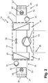
- Fig. 2 shows a further schematic design of a cooling module 10, which is also coupled to a coolant circuit 30 and a heating medium circuit 40.
- the in Fig. 2 The cooling module 10 shown, the compressor 18 is cooled via a separate cooling circuit 26 which is led out of the housing 12. Connections which are not designated are also provided for this purpose. Another coolant, which is cooled with ambient air, for example via a plate heat exchanger, can be guided in the cooling circuit. In addition, a delivery device can also be provided, which delivers a coolant guided in the cooling circuit 26.
- a heat exchanger is arranged in the area of the evaporator 20, for example, which supplies heat to the refrigerant and thus cools the compressor 18.
- a further conveying device can be provided for such an internal additional cooling circuit.
Landscapes
- Engineering & Computer Science (AREA)
- Physics & Mathematics (AREA)
- Mechanical Engineering (AREA)
- Thermal Sciences (AREA)
- General Engineering & Computer Science (AREA)
- Chemical & Material Sciences (AREA)
- Combustion & Propulsion (AREA)
- Devices That Are Associated With Refrigeration Equipment (AREA)
- Cooling Or The Like Of Electrical Apparatus (AREA)
Priority Applications (1)
| Application Number | Priority Date | Filing Date | Title |
|---|---|---|---|
| PL17737802T PL3485205T3 (pl) | 2016-07-13 | 2017-07-12 | Moduł chłodniczy |
Applications Claiming Priority (2)
| Application Number | Priority Date | Filing Date | Title |
|---|---|---|---|
| DE102016112851.1A DE102016112851A1 (de) | 2016-07-13 | 2016-07-13 | Kältemodul |
| PCT/EP2017/067496 WO2018011246A1 (de) | 2016-07-13 | 2017-07-12 | Kältemodul |
Publications (2)
| Publication Number | Publication Date |
|---|---|
| EP3485205A1 EP3485205A1 (de) | 2019-05-22 |
| EP3485205B1 true EP3485205B1 (de) | 2020-08-26 |
Family
ID=59315636
Family Applications (1)
| Application Number | Title | Priority Date | Filing Date |
|---|---|---|---|
| EP17737802.3A Active EP3485205B1 (de) | 2016-07-13 | 2017-07-12 | Kältemodul |
Country Status (7)
| Country | Link |
|---|---|
| US (1) | US11365910B2 (pl) |
| EP (1) | EP3485205B1 (pl) |
| DE (1) | DE102016112851A1 (pl) |
| DK (1) | DK3485205T3 (pl) |
| ES (1) | ES2834621T3 (pl) |
| PL (1) | PL3485205T3 (pl) |
| WO (1) | WO2018011246A1 (pl) |
Families Citing this family (10)
| Publication number | Priority date | Publication date | Assignee | Title |
|---|---|---|---|---|
| DE102016112851A1 (de) * | 2016-07-13 | 2018-01-18 | Viessmann Werke Gmbh & Co Kg | Kältemodul |
| DE102019123044A1 (de) * | 2019-08-28 | 2021-03-04 | Vaillant Gmbh | Leckagedetektion |
| JP7528099B2 (ja) | 2019-09-04 | 2024-08-05 | ダイキン工業株式会社 | 圧縮機ユニット及び冷凍装置 |
| JP2023007129A (ja) * | 2021-07-01 | 2023-01-18 | ダイキン工業株式会社 | 空気調和システム |
| EP4596994A1 (de) | 2021-12-07 | 2025-08-06 | Glen Dimplex Deutschland GmbH | Kältemittelanlage sowie kältemittelmodul |
| WO2023229939A1 (en) * | 2022-05-23 | 2023-11-30 | Rheem Manufacturing Company | Heat pump systems for hand washing unit and/or bottle filling unit |
| EP4532990A1 (en) * | 2022-05-30 | 2025-04-09 | BDR Thermea Group B.V. | Heat pump unit, assembly of a heat pump unit and a tank and a method of installing a heat pump unit and a tank |
| EP4361513A1 (en) * | 2022-10-27 | 2024-05-01 | BDR Thermea Group B.V. | Enclosure for a heat pump |
| DE102023212555A1 (de) | 2023-12-12 | 2025-06-12 | Glen Dimplex Deutschland Gmbh | Kältemodul Verfahren zum Betrieb eines Kältemoduls |
| DE102024123156B3 (de) * | 2024-08-14 | 2025-08-21 | Rittal Gmbh & Co. Kg | Kühlgerät für einen Schaltschrank aufweisend eine einen Kühlkreislauf gasdicht umschließende Einhausung |
Family Cites Families (24)
| Publication number | Priority date | Publication date | Assignee | Title |
|---|---|---|---|---|
| DE2807990A1 (de) * | 1978-02-23 | 1979-08-30 | Vaillant Joh Gmbh & Co | Sorptionswaermepumpe |
| NL8103020A (nl) * | 1980-06-27 | 1982-01-18 | Philips Nv | Inrichting voor het verwarmen met een warmtepomp. |
| US4766732A (en) * | 1987-10-26 | 1988-08-30 | Julius Rubin | Chamber refrigerated by solid carbon dioxide |
| DE9106051U1 (de) | 1991-05-16 | 1991-12-05 | RAUM-KLIMA Technologie-GMBH., 7570 Baden-Baden | Kälte- oder Wärmeaggregat |
| DE9319874U1 (de) | 1993-12-24 | 1994-03-31 | Hagenuk Fahrzeugklima GmbH, 04435 Schkeuditz | Heizungs- und Kühlanlage |
| FR2827948B1 (fr) * | 2001-07-26 | 2016-07-29 | Jacques Bernier | Pompe a chaleur a dispositif de ventilation de securite |
| WO2006052195A1 (en) | 2004-11-11 | 2006-05-18 | Ola Wilhelm Lindborg | A cold-or heat-generating arrangement |
| DE102008003630A1 (de) * | 2008-01-09 | 2009-07-16 | Helioplus Energy Systems Gmbh | Hybridklimatisierungssystem |
| DE102009029392A1 (de) | 2009-09-11 | 2011-03-24 | WESKA Kälteanlagen GmbH | Explosionsgeschützte Kälteanlage mit brennbarem Kältemittel |
| US20120291457A1 (en) * | 2011-05-17 | 2012-11-22 | Service Solutions U.S. Llc | Pressure Decay Leak Check Method and Apparatus |
| CH704990A1 (de) | 2011-05-20 | 2012-11-30 | Remo Meister | Verfahren zum Reparieren bzw. Überprüfen einer in einem druckdicht geschlossenen Behälter untergebrachten, insbesondere kältetechnischen Anlage sowie Behälter zur Durchführung des Verfahrens. |
| WO2013169874A1 (en) * | 2012-05-08 | 2013-11-14 | Sheetak, Inc. | Thermoelectric heat pump |
| DE102012112347B4 (de) * | 2012-12-14 | 2014-10-02 | Thomas Hahn | Wärme- und Kältebereitstellungsvorrichtung |
| DE102013201903A1 (de) * | 2013-02-06 | 2014-08-07 | E.G.O. Elektro-Gerätebau GmbH | Wärmepumpenvorrichtung, Verwendung einer Pumpe mit beheizbarer Pumpenkammer in einer Wärmepumpenvorrichtung und Verfahren zum Betrieb einer Wärmepumpenvorrichtung |
| DE102014217108A1 (de) * | 2014-08-27 | 2016-03-03 | Robert Bosch Gmbh | Adsorbereinrichtung, Wärmeeinrichtung, Kraftfahrzeug |
| DE102014112545B4 (de) * | 2014-09-01 | 2022-06-02 | Denso Automotive Deutschland Gmbh | Kompaktaggregat für ein Kraftfahrzeug und Verfahren zur Notfallbehandlung einer Kraftfahrzeugklimaanlage |
| DK3106780T3 (en) * | 2015-06-17 | 2018-02-26 | Vaillant Gmbh | HEAT PUMP SYSTEM |
| CN204957371U (zh) * | 2015-09-16 | 2016-01-13 | 王珂 | 三层器皿 |
| JP2019509461A (ja) * | 2016-03-24 | 2019-04-04 | ビーエーエスエフ ソシエタス・ヨーロピアBasf Se | 磁気熱量装置 |
| JP2017215088A (ja) * | 2016-05-31 | 2017-12-07 | サンデン・リビングエンバイロメントシステム株式会社 | ヒートポンプ式給湯装置 |
| DE102016111292B4 (de) * | 2016-06-21 | 2018-03-29 | Futron GmbH | System zum Konditionieren von Luft eines Raumes und Anordnung des Systems |
| DE202016103305U1 (de) * | 2016-06-22 | 2016-07-07 | Futron GmbH | Explosionsgeschützte Vorrichtung zum Temperieren von Wärmeträgerfluiden |
| DE102016112851A1 (de) * | 2016-07-13 | 2018-01-18 | Viessmann Werke Gmbh & Co Kg | Kältemodul |
| DE102016218000B3 (de) * | 2016-09-20 | 2017-10-05 | Bruker Biospin Gmbh | Kryostatenanordnung mit einem Vakuumbehälter und einem zu kühlenden Objekt, mit evakuierbarem Hohlraum |
-
2016
- 2016-07-13 DE DE102016112851.1A patent/DE102016112851A1/de not_active Withdrawn
-
2017
- 2017-07-12 ES ES17737802T patent/ES2834621T3/es active Active
- 2017-07-12 US US16/317,773 patent/US11365910B2/en active Active
- 2017-07-12 EP EP17737802.3A patent/EP3485205B1/de active Active
- 2017-07-12 WO PCT/EP2017/067496 patent/WO2018011246A1/de not_active Ceased
- 2017-07-12 PL PL17737802T patent/PL3485205T3/pl unknown
- 2017-07-12 DK DK17737802.3T patent/DK3485205T3/da active
Non-Patent Citations (1)
| Title |
|---|
| None * |
Also Published As
| Publication number | Publication date |
|---|---|
| US20190234659A1 (en) | 2019-08-01 |
| US11365910B2 (en) | 2022-06-21 |
| PL3485205T3 (pl) | 2021-03-08 |
| DE102016112851A1 (de) | 2018-01-18 |
| EP3485205A1 (de) | 2019-05-22 |
| ES2834621T3 (es) | 2021-06-18 |
| WO2018011246A1 (de) | 2018-01-18 |
| DK3485205T3 (da) | 2020-11-30 |
Similar Documents
| Publication | Publication Date | Title |
|---|---|---|
| EP3485205B1 (de) | Kältemodul | |
| DE60013666T2 (de) | Gerät zum Kühlen der Leistungselektronik eines Kälteverdichterantriebs | |
| DE102019124531A1 (de) | Sicherheitsspülvorrichtung für eine Wärmepumpe | |
| DE202016103305U1 (de) | Explosionsgeschützte Vorrichtung zum Temperieren von Wärmeträgerfluiden | |
| DE112010001984T5 (de) | Explosionssichere Umhausungen mit einer aktiven Wärmeverwaltung mittels Wärmetausch | |
| DE102010013313A1 (de) | Gehäuse mit erweitertem Umgebungstemperaturbereich | |
| EP2128514B1 (de) | Leitung zur Führung eines Mediums | |
| DE4413130C2 (de) | Kühlgerät | |
| WO2017186336A1 (de) | Wasserstofftankstelle mit flüssigem wasserstoff | |
| EP2802194B1 (de) | Druckfest gekapseltes Gehäuse mit einer Kühlvorrichtung | |
| EP3770520B1 (de) | Brandschutzvorrichtung | |
| EP2065555B1 (de) | Verfahren zum Betrieb einer Verdichtervorrichtung und zugehörige Verdichtervorrichtung | |
| DE4413128A1 (de) | Kühlgerät | |
| DE102017012125A1 (de) | Wärmeübertragungseinrichtung für die Kältebereitstellung in Kühlfahrzeugen, deren Kraftfahrzeugmotor mit LNG angetrieben wird | |
| EP3516171A1 (de) | Schraubenkompressor für ein nutzfahrzeug | |
| CH702754A2 (de) | Überwachungseinrichtung für einen Schiebeverschluss, einen Giessrohrwechsler oder dergleichen an einem metallurgischen Gefäss. | |
| GB2428896A (en) | Detecting a leak in a cooling system | |
| EP3786516A2 (de) | Verfahren zur zeitlichen druckanstiegsmessung in einem wärmepumpengehäuse einer innen aufgestellten wärmepumpenanlage und eine druckmessvorrichtung | |
| DE102019121496A1 (de) | Sicherheitsspülvorrichtung für eine Wärmepumpe | |
| DE102006033030A1 (de) | Kühlvorrichtung | |
| DE102010028950A1 (de) | Vorrichtung zum Kühlen und Rechner-Racks | |
| EP3772622B1 (de) | Schutz gegen übertritt von kältemittel in einen heizkreislauf nach schäden durch gefrieren von wärmeträgermedium in einem wärmeübertrager | |
| DE102015209536B4 (de) | Kälteanlage | |
| EP4248151A1 (de) | Verfahren zum erkennen von leckagen in einem kältekreis einer kompressionskältemaschine und leckagedetektiersystem | |
| EP3712531A1 (de) | Sicherheitsspülvorrichtung für eine wärmepumpe |
Legal Events
| Date | Code | Title | Description |
|---|---|---|---|
| STAA | Information on the status of an ep patent application or granted ep patent |
Free format text: STATUS: UNKNOWN |
|
| STAA | Information on the status of an ep patent application or granted ep patent |
Free format text: STATUS: THE INTERNATIONAL PUBLICATION HAS BEEN MADE |
|
| PUAI | Public reference made under article 153(3) epc to a published international application that has entered the european phase |
Free format text: ORIGINAL CODE: 0009012 |
|
| STAA | Information on the status of an ep patent application or granted ep patent |
Free format text: STATUS: REQUEST FOR EXAMINATION WAS MADE |
|
| 17P | Request for examination filed |
Effective date: 20181217 |
|
| AK | Designated contracting states |
Kind code of ref document: A1 Designated state(s): AL AT BE BG CH CY CZ DE DK EE ES FI FR GB GR HR HU IE IS IT LI LT LU LV MC MK MT NL NO PL PT RO RS SE SI SK SM TR |
|
| AX | Request for extension of the european patent |
Extension state: BA ME |
|
| DAV | Request for validation of the european patent (deleted) | ||
| DAX | Request for extension of the european patent (deleted) | ||
| GRAP | Despatch of communication of intention to grant a patent |
Free format text: ORIGINAL CODE: EPIDOSNIGR1 |
|
| STAA | Information on the status of an ep patent application or granted ep patent |
Free format text: STATUS: GRANT OF PATENT IS INTENDED |
|
| INTG | Intention to grant announced |
Effective date: 20200313 |
|
| GRAS | Grant fee paid |
Free format text: ORIGINAL CODE: EPIDOSNIGR3 |
|
| GRAA | (expected) grant |
Free format text: ORIGINAL CODE: 0009210 |
|
| STAA | Information on the status of an ep patent application or granted ep patent |
Free format text: STATUS: THE PATENT HAS BEEN GRANTED |
|
| AK | Designated contracting states |
Kind code of ref document: B1 Designated state(s): AL AT BE BG CH CY CZ DE DK EE ES FI FR GB GR HR HU IE IS IT LI LT LU LV MC MK MT NL NO PL PT RO RS SE SI SK SM TR |
|
| REG | Reference to a national code |
Ref country code: GB Ref legal event code: FG4D Free format text: NOT ENGLISH |
|
| REG | Reference to a national code |
Ref country code: CH Ref legal event code: EP |
|
| REG | Reference to a national code |
Ref country code: DE Ref legal event code: R096 Ref document number: 502017006945 Country of ref document: DE |
|
| REG | Reference to a national code |
Ref country code: AT Ref legal event code: REF Ref document number: 1306773 Country of ref document: AT Kind code of ref document: T Effective date: 20200915 |
|
| REG | Reference to a national code |
Ref country code: IE Ref legal event code: FG4D Free format text: LANGUAGE OF EP DOCUMENT: GERMAN |
|
| RAP2 | Party data changed (patent owner data changed or rights of a patent transferred) |
Owner name: VIESSMANN REFRIGERATION SOLUTIONS GMBH |
|
| REG | Reference to a national code |
Ref country code: DE Ref legal event code: R082 Ref document number: 502017006945 Country of ref document: DE Representative=s name: DIE PATENTERIE GBR, DE Ref country code: DE Ref legal event code: R081 Ref document number: 502017006945 Country of ref document: DE Owner name: VIESSMANN REFRIGERATION SOLUTIONS GMBH, DE Free format text: FORMER OWNER: VIESSMANN WERKE GMBH & CO KG, 35108 ALLENDORF, DE |
|
| REG | Reference to a national code |
Ref country code: FI Ref legal event code: FGE |
|
| REG | Reference to a national code |
Ref country code: DK Ref legal event code: T3 Effective date: 20201125 |
|
| REG | Reference to a national code |
Ref country code: NL Ref legal event code: FP |
|
| REG | Reference to a national code |
Ref country code: LT Ref legal event code: MG4D |
|
| PG25 | Lapsed in a contracting state [announced via postgrant information from national office to epo] |
Ref country code: LT Free format text: LAPSE BECAUSE OF FAILURE TO SUBMIT A TRANSLATION OF THE DESCRIPTION OR TO PAY THE FEE WITHIN THE PRESCRIBED TIME-LIMIT Effective date: 20200826 Ref country code: SE Free format text: LAPSE BECAUSE OF FAILURE TO SUBMIT A TRANSLATION OF THE DESCRIPTION OR TO PAY THE FEE WITHIN THE PRESCRIBED TIME-LIMIT Effective date: 20200826 Ref country code: HR Free format text: LAPSE BECAUSE OF FAILURE TO SUBMIT A TRANSLATION OF THE DESCRIPTION OR TO PAY THE FEE WITHIN THE PRESCRIBED TIME-LIMIT Effective date: 20200826 Ref country code: PT Free format text: LAPSE BECAUSE OF FAILURE TO SUBMIT A TRANSLATION OF THE DESCRIPTION OR TO PAY THE FEE WITHIN THE PRESCRIBED TIME-LIMIT Effective date: 20201228 Ref country code: NO Free format text: LAPSE BECAUSE OF FAILURE TO SUBMIT A TRANSLATION OF THE DESCRIPTION OR TO PAY THE FEE WITHIN THE PRESCRIBED TIME-LIMIT Effective date: 20201126 Ref country code: GR Free format text: LAPSE BECAUSE OF FAILURE TO SUBMIT A TRANSLATION OF THE DESCRIPTION OR TO PAY THE FEE WITHIN THE PRESCRIBED TIME-LIMIT Effective date: 20201127 Ref country code: BG Free format text: LAPSE BECAUSE OF FAILURE TO SUBMIT A TRANSLATION OF THE DESCRIPTION OR TO PAY THE FEE WITHIN THE PRESCRIBED TIME-LIMIT Effective date: 20201126 |
|
| PG25 | Lapsed in a contracting state [announced via postgrant information from national office to epo] |
Ref country code: RS Free format text: LAPSE BECAUSE OF FAILURE TO SUBMIT A TRANSLATION OF THE DESCRIPTION OR TO PAY THE FEE WITHIN THE PRESCRIBED TIME-LIMIT Effective date: 20200826 Ref country code: LV Free format text: LAPSE BECAUSE OF FAILURE TO SUBMIT A TRANSLATION OF THE DESCRIPTION OR TO PAY THE FEE WITHIN THE PRESCRIBED TIME-LIMIT Effective date: 20200826 Ref country code: IS Free format text: LAPSE BECAUSE OF FAILURE TO SUBMIT A TRANSLATION OF THE DESCRIPTION OR TO PAY THE FEE WITHIN THE PRESCRIBED TIME-LIMIT Effective date: 20201226 |
|
| PG25 | Lapsed in a contracting state [announced via postgrant information from national office to epo] |
Ref country code: CZ Free format text: LAPSE BECAUSE OF FAILURE TO SUBMIT A TRANSLATION OF THE DESCRIPTION OR TO PAY THE FEE WITHIN THE PRESCRIBED TIME-LIMIT Effective date: 20200826 Ref country code: RO Free format text: LAPSE BECAUSE OF FAILURE TO SUBMIT A TRANSLATION OF THE DESCRIPTION OR TO PAY THE FEE WITHIN THE PRESCRIBED TIME-LIMIT Effective date: 20200826 Ref country code: EE Free format text: LAPSE BECAUSE OF FAILURE TO SUBMIT A TRANSLATION OF THE DESCRIPTION OR TO PAY THE FEE WITHIN THE PRESCRIBED TIME-LIMIT Effective date: 20200826 Ref country code: SM Free format text: LAPSE BECAUSE OF FAILURE TO SUBMIT A TRANSLATION OF THE DESCRIPTION OR TO PAY THE FEE WITHIN THE PRESCRIBED TIME-LIMIT Effective date: 20200826 |
|
| REG | Reference to a national code |
Ref country code: GB Ref legal event code: 732E Free format text: REGISTERED BETWEEN 20210415 AND 20210421 |
|
| REG | Reference to a national code |
Ref country code: DE Ref legal event code: R097 Ref document number: 502017006945 Country of ref document: DE |
|
| PG25 | Lapsed in a contracting state [announced via postgrant information from national office to epo] |
Ref country code: AL Free format text: LAPSE BECAUSE OF FAILURE TO SUBMIT A TRANSLATION OF THE DESCRIPTION OR TO PAY THE FEE WITHIN THE PRESCRIBED TIME-LIMIT Effective date: 20200826 |
|
| REG | Reference to a national code |
Ref country code: ES Ref legal event code: FG2A Ref document number: 2834621 Country of ref document: ES Kind code of ref document: T3 Effective date: 20210618 |
|
| PG25 | Lapsed in a contracting state [announced via postgrant information from national office to epo] |
Ref country code: SK Free format text: LAPSE BECAUSE OF FAILURE TO SUBMIT A TRANSLATION OF THE DESCRIPTION OR TO PAY THE FEE WITHIN THE PRESCRIBED TIME-LIMIT Effective date: 20200826 |
|
| REG | Reference to a national code |
Ref country code: NL Ref legal event code: PD Owner name: VIESSMANN REFRIGERATION SOLUTIONS GMBH; DE Free format text: DETAILS ASSIGNMENT: CHANGE OF OWNER(S), ASSIGNMENT; FORMER OWNER NAME: VIESSMANN WERKE GMBH & CO. KG Effective date: 20210614 |
|
| PLBE | No opposition filed within time limit |
Free format text: ORIGINAL CODE: 0009261 |
|
| STAA | Information on the status of an ep patent application or granted ep patent |
Free format text: STATUS: NO OPPOSITION FILED WITHIN TIME LIMIT |
|
| 26N | No opposition filed |
Effective date: 20210527 |
|
| PG25 | Lapsed in a contracting state [announced via postgrant information from national office to epo] |
Ref country code: SI Free format text: LAPSE BECAUSE OF FAILURE TO SUBMIT A TRANSLATION OF THE DESCRIPTION OR TO PAY THE FEE WITHIN THE PRESCRIBED TIME-LIMIT Effective date: 20200826 |
|
| REG | Reference to a national code |
Ref country code: CH Ref legal event code: PL |
|
| PG25 | Lapsed in a contracting state [announced via postgrant information from national office to epo] |
Ref country code: MC Free format text: LAPSE BECAUSE OF FAILURE TO SUBMIT A TRANSLATION OF THE DESCRIPTION OR TO PAY THE FEE WITHIN THE PRESCRIBED TIME-LIMIT Effective date: 20200826 |
|
| REG | Reference to a national code |
Ref country code: BE Ref legal event code: MM Effective date: 20210731 |
|
| REG | Reference to a national code |
Ref country code: AT Ref legal event code: PC Ref document number: 1306773 Country of ref document: AT Kind code of ref document: T Owner name: VIESSMANN REFRIGERATION SOLUTIONS GMBH, DE Effective date: 20220314 |
|
| PG25 | Lapsed in a contracting state [announced via postgrant information from national office to epo] |
Ref country code: LI Free format text: LAPSE BECAUSE OF NON-PAYMENT OF DUE FEES Effective date: 20210731 Ref country code: CH Free format text: LAPSE BECAUSE OF NON-PAYMENT OF DUE FEES Effective date: 20210731 |
|
| PG25 | Lapsed in a contracting state [announced via postgrant information from national office to epo] |
Ref country code: LU Free format text: LAPSE BECAUSE OF NON-PAYMENT OF DUE FEES Effective date: 20210712 |
|
| PG25 | Lapsed in a contracting state [announced via postgrant information from national office to epo] |
Ref country code: IE Free format text: LAPSE BECAUSE OF NON-PAYMENT OF DUE FEES Effective date: 20210712 Ref country code: BE Free format text: LAPSE BECAUSE OF NON-PAYMENT OF DUE FEES Effective date: 20210731 |
|
| PGFP | Annual fee paid to national office [announced via postgrant information from national office to epo] |
Ref country code: NL Payment date: 20220724 Year of fee payment: 6 |
|
| PGFP | Annual fee paid to national office [announced via postgrant information from national office to epo] |
Ref country code: IT Payment date: 20220729 Year of fee payment: 6 Ref country code: GB Payment date: 20220716 Year of fee payment: 6 |
|
| PGFP | Annual fee paid to national office [announced via postgrant information from national office to epo] |
Ref country code: FR Payment date: 20220726 Year of fee payment: 6 |
|
| P01 | Opt-out of the competence of the unified patent court (upc) registered |
Effective date: 20230512 |
|
| PG25 | Lapsed in a contracting state [announced via postgrant information from national office to epo] |
Ref country code: CY Free format text: LAPSE BECAUSE OF FAILURE TO SUBMIT A TRANSLATION OF THE DESCRIPTION OR TO PAY THE FEE WITHIN THE PRESCRIBED TIME-LIMIT Effective date: 20200826 |
|
| PG25 | Lapsed in a contracting state [announced via postgrant information from national office to epo] |
Ref country code: HU Free format text: LAPSE BECAUSE OF FAILURE TO SUBMIT A TRANSLATION OF THE DESCRIPTION OR TO PAY THE FEE WITHIN THE PRESCRIBED TIME-LIMIT; INVALID AB INITIO Effective date: 20170712 |
|
| PGFP | Annual fee paid to national office [announced via postgrant information from national office to epo] |
Ref country code: PL Payment date: 20230623 Year of fee payment: 7 |
|
| PGFP | Annual fee paid to national office [announced via postgrant information from national office to epo] |
Ref country code: TR Payment date: 20230706 Year of fee payment: 7 Ref country code: FI Payment date: 20230721 Year of fee payment: 7 Ref country code: ES Payment date: 20230801 Year of fee payment: 7 Ref country code: AT Payment date: 20230719 Year of fee payment: 7 |
|
| PGFP | Annual fee paid to national office [announced via postgrant information from national office to epo] |
Ref country code: DK Payment date: 20230720 Year of fee payment: 7 Ref country code: DE Payment date: 20230531 Year of fee payment: 7 |
|
| REG | Reference to a national code |
Ref country code: NL Ref legal event code: MM Effective date: 20230801 |
|
| GBPC | Gb: european patent ceased through non-payment of renewal fee |
Effective date: 20230712 |
|
| PG25 | Lapsed in a contracting state [announced via postgrant information from national office to epo] |
Ref country code: NL Free format text: LAPSE BECAUSE OF NON-PAYMENT OF DUE FEES Effective date: 20230801 |
|
| PG25 | Lapsed in a contracting state [announced via postgrant information from national office to epo] |
Ref country code: NL Free format text: LAPSE BECAUSE OF NON-PAYMENT OF DUE FEES Effective date: 20230801 Ref country code: MK Free format text: LAPSE BECAUSE OF FAILURE TO SUBMIT A TRANSLATION OF THE DESCRIPTION OR TO PAY THE FEE WITHIN THE PRESCRIBED TIME-LIMIT Effective date: 20200826 Ref country code: GB Free format text: LAPSE BECAUSE OF NON-PAYMENT OF DUE FEES Effective date: 20230712 |
|
| PG25 | Lapsed in a contracting state [announced via postgrant information from national office to epo] |
Ref country code: FR Free format text: LAPSE BECAUSE OF NON-PAYMENT OF DUE FEES Effective date: 20230731 |
|
| PG25 | Lapsed in a contracting state [announced via postgrant information from national office to epo] |
Ref country code: IT Free format text: LAPSE BECAUSE OF NON-PAYMENT OF DUE FEES Effective date: 20230712 |
|
| PG25 | Lapsed in a contracting state [announced via postgrant information from national office to epo] |
Ref country code: MT Free format text: LAPSE BECAUSE OF FAILURE TO SUBMIT A TRANSLATION OF THE DESCRIPTION OR TO PAY THE FEE WITHIN THE PRESCRIBED TIME-LIMIT Effective date: 20200826 |
|
| REG | Reference to a national code |
Ref country code: DE Ref legal event code: R119 Ref document number: 502017006945 Country of ref document: DE |
|
| REG | Reference to a national code |
Ref country code: DK Ref legal event code: EBP Effective date: 20240731 |
|
| REG | Reference to a national code |
Ref country code: AT Ref legal event code: MM01 Ref document number: 1306773 Country of ref document: AT Kind code of ref document: T Effective date: 20240712 |
|
| PG25 | Lapsed in a contracting state [announced via postgrant information from national office to epo] |
Ref country code: DE Free format text: LAPSE BECAUSE OF NON-PAYMENT OF DUE FEES Effective date: 20250201 |
|
| PG25 | Lapsed in a contracting state [announced via postgrant information from national office to epo] |
Ref country code: FI Free format text: LAPSE BECAUSE OF NON-PAYMENT OF DUE FEES Effective date: 20240712 |
|
| PG25 | Lapsed in a contracting state [announced via postgrant information from national office to epo] |
Ref country code: AT Free format text: LAPSE BECAUSE OF NON-PAYMENT OF DUE FEES Effective date: 20240712 |
|
| PG25 | Lapsed in a contracting state [announced via postgrant information from national office to epo] |
Ref country code: DK Free format text: LAPSE BECAUSE OF NON-PAYMENT OF DUE FEES Effective date: 20240731 |
|
| REG | Reference to a national code |
Ref country code: ES Ref legal event code: FD2A Effective date: 20250829 |
|
| PG25 | Lapsed in a contracting state [announced via postgrant information from national office to epo] |
Ref country code: ES Free format text: LAPSE BECAUSE OF NON-PAYMENT OF DUE FEES Effective date: 20240713 |
|
| PG25 | Lapsed in a contracting state [announced via postgrant information from national office to epo] |
Ref country code: PL Free format text: LAPSE BECAUSE OF NON-PAYMENT OF DUE FEES Effective date: 20240712 |