EP3484559B1 - Inflatable radial artery compression device - Google Patents
Inflatable radial artery compression device Download PDFInfo
- Publication number
- EP3484559B1 EP3484559B1 EP17831575.0A EP17831575A EP3484559B1 EP 3484559 B1 EP3484559 B1 EP 3484559B1 EP 17831575 A EP17831575 A EP 17831575A EP 3484559 B1 EP3484559 B1 EP 3484559B1
- Authority
- EP
- European Patent Office
- Prior art keywords
- radial artery
- compression device
- artery compression
- frame
- inflatable chamber
- Prior art date
- Legal status (The legal status is an assumption and is not a legal conclusion. Google has not performed a legal analysis and makes no representation as to the accuracy of the status listed.)
- Active
Links
- 210000002321 radial artery Anatomy 0.000 title claims description 160
- 230000006835 compression Effects 0.000 title claims description 158
- 238000007906 compression Methods 0.000 title claims description 158
- 239000012530 fluid Substances 0.000 claims description 37
- 210000000707 wrist Anatomy 0.000 claims description 24
- 238000004891 communication Methods 0.000 claims description 12
- 230000002093 peripheral effect Effects 0.000 claims description 4
- 238000000034 method Methods 0.000 description 25
- 230000023597 hemostasis Effects 0.000 description 10
- 230000000740 bleeding effect Effects 0.000 description 6
- 210000002559 ulnar artery Anatomy 0.000 description 5
- 238000013152 interventional procedure Methods 0.000 description 3
- 239000000853 adhesive Substances 0.000 description 2
- 230000001070 adhesive effect Effects 0.000 description 2
- 230000008901 benefit Effects 0.000 description 2
- 239000008280 blood Substances 0.000 description 2
- 210000004369 blood Anatomy 0.000 description 2
- 239000003990 capacitor Substances 0.000 description 2
- 230000008859 change Effects 0.000 description 2
- 230000003993 interaction Effects 0.000 description 2
- 239000000463 material Substances 0.000 description 2
- 230000008685 targeting Effects 0.000 description 2
- 238000011144 upstream manufacturing Methods 0.000 description 2
- 239000002699 waste material Substances 0.000 description 2
- 210000001367 artery Anatomy 0.000 description 1
- 230000017531 blood circulation Effects 0.000 description 1
- 238000009530 blood pressure measurement Methods 0.000 description 1
- 238000010276 construction Methods 0.000 description 1
- 230000008878 coupling Effects 0.000 description 1
- 238000010168 coupling process Methods 0.000 description 1
- 238000005859 coupling reaction Methods 0.000 description 1
- 230000001419 dependent effect Effects 0.000 description 1
- 230000035876 healing Effects 0.000 description 1
- 238000003780 insertion Methods 0.000 description 1
- 230000037431 insertion Effects 0.000 description 1
- 239000007788 liquid Substances 0.000 description 1
- 230000007246 mechanism Effects 0.000 description 1
- 229920002635 polyurethane Polymers 0.000 description 1
- 239000004814 polyurethane Substances 0.000 description 1
- 238000003825 pressing Methods 0.000 description 1
- 230000008569 process Effects 0.000 description 1
- 230000007704 transition Effects 0.000 description 1
- 210000005166 vasculature Anatomy 0.000 description 1
- 230000000007 visual effect Effects 0.000 description 1
- 238000003466 welding Methods 0.000 description 1
Images


Classifications
-
- A—HUMAN NECESSITIES
- A61—MEDICAL OR VETERINARY SCIENCE; HYGIENE
- A61B—DIAGNOSIS; SURGERY; IDENTIFICATION
- A61B17/00—Surgical instruments, devices or methods, e.g. tourniquets
- A61B17/12—Surgical instruments, devices or methods, e.g. tourniquets for ligaturing or otherwise compressing tubular parts of the body, e.g. blood vessels, umbilical cord
- A61B17/132—Tourniquets
- A61B17/135—Tourniquets inflatable
-
- A—HUMAN NECESSITIES
- A61—MEDICAL OR VETERINARY SCIENCE; HYGIENE
- A61B—DIAGNOSIS; SURGERY; IDENTIFICATION
- A61B17/00—Surgical instruments, devices or methods, e.g. tourniquets
- A61B17/12—Surgical instruments, devices or methods, e.g. tourniquets for ligaturing or otherwise compressing tubular parts of the body, e.g. blood vessels, umbilical cord
- A61B17/132—Tourniquets
- A61B17/1322—Tourniquets comprising a flexible encircling member
- A61B17/1325—Tourniquets comprising a flexible encircling member with means for applying local pressure
-
- A—HUMAN NECESSITIES
- A61—MEDICAL OR VETERINARY SCIENCE; HYGIENE
- A61B—DIAGNOSIS; SURGERY; IDENTIFICATION
- A61B17/00—Surgical instruments, devices or methods, e.g. tourniquets
- A61B17/12—Surgical instruments, devices or methods, e.g. tourniquets for ligaturing or otherwise compressing tubular parts of the body, e.g. blood vessels, umbilical cord
- A61B17/132—Tourniquets
- A61B17/135—Tourniquets inflatable
- A61B17/1355—Automated control means therefor
-
- A—HUMAN NECESSITIES
- A61—MEDICAL OR VETERINARY SCIENCE; HYGIENE
- A61B—DIAGNOSIS; SURGERY; IDENTIFICATION
- A61B17/00—Surgical instruments, devices or methods, e.g. tourniquets
- A61B2017/00017—Electrical control of surgical instruments
- A61B2017/00115—Electrical control of surgical instruments with audible or visual output
- A61B2017/00119—Electrical control of surgical instruments with audible or visual output alarm; indicating an abnormal situation
-
- A—HUMAN NECESSITIES
- A61—MEDICAL OR VETERINARY SCIENCE; HYGIENE
- A61B—DIAGNOSIS; SURGERY; IDENTIFICATION
- A61B17/00—Surgical instruments, devices or methods, e.g. tourniquets
- A61B2017/00017—Electrical control of surgical instruments
- A61B2017/00199—Electrical control of surgical instruments with a console, e.g. a control panel with a display
-
- A—HUMAN NECESSITIES
- A61—MEDICAL OR VETERINARY SCIENCE; HYGIENE
- A61B—DIAGNOSIS; SURGERY; IDENTIFICATION
- A61B17/00—Surgical instruments, devices or methods, e.g. tourniquets
- A61B2017/00017—Electrical control of surgical instruments
- A61B2017/00221—Electrical control of surgical instruments with wireless transmission of data, e.g. by infrared radiation or radiowaves
-
- A—HUMAN NECESSITIES
- A61—MEDICAL OR VETERINARY SCIENCE; HYGIENE
- A61B—DIAGNOSIS; SURGERY; IDENTIFICATION
- A61B17/00—Surgical instruments, devices or methods, e.g. tourniquets
- A61B2017/0042—Surgical instruments, devices or methods, e.g. tourniquets with special provisions for gripping
- A61B2017/00442—Surgical instruments, devices or methods, e.g. tourniquets with special provisions for gripping connectable to wrist or forearm
-
- A—HUMAN NECESSITIES
- A61—MEDICAL OR VETERINARY SCIENCE; HYGIENE
- A61B—DIAGNOSIS; SURGERY; IDENTIFICATION
- A61B17/00—Surgical instruments, devices or methods, e.g. tourniquets
- A61B2017/00535—Surgical instruments, devices or methods, e.g. tourniquets pneumatically or hydraulically operated
- A61B2017/00544—Surgical instruments, devices or methods, e.g. tourniquets pneumatically or hydraulically operated pneumatically
-
- A—HUMAN NECESSITIES
- A61—MEDICAL OR VETERINARY SCIENCE; HYGIENE
- A61B—DIAGNOSIS; SURGERY; IDENTIFICATION
- A61B17/00—Surgical instruments, devices or methods, e.g. tourniquets
- A61B2017/00681—Aspects not otherwise provided for
- A61B2017/00734—Aspects not otherwise provided for battery operated
-
- A—HUMAN NECESSITIES
- A61—MEDICAL OR VETERINARY SCIENCE; HYGIENE
- A61B—DIAGNOSIS; SURGERY; IDENTIFICATION
- A61B17/00—Surgical instruments, devices or methods, e.g. tourniquets
- A61B2017/00831—Material properties
- A61B2017/00902—Material properties transparent or translucent
- A61B2017/00907—Material properties transparent or translucent for light
Definitions
- the present disclosure relates generally to the field of medical devices. More particularly, some embodiments relate to compression devices, including radial artery compression devices with an inflatable chamber.
- compression devices including radial artery compression devices with an inflatable chamber.
- the prior art documents US2012/245675 A1 , WO2012/126154 A1 , US 2015/018869 A1 and US 2015/327871 disclose devices for applying targeted force to a radial access puncture site to aid in arresting bleeding at the puncture site.
- the devices disclosed comprise a band for placing the device at a patient's wrist, and an inflatable balloon attached to the band and disposed over the puncture site during use. The inflated balloon applies pressure to the puncture site.
- the devices further comprise targeting indicia disposed, e.g. on the balloon and/or on the rigid or semirigid member, e.g. a backing layer of the balloon. The targeting indicia serve to identify that portion of the balloon to be positioned on the puncture site so that the inflated balloon applies pressure
- the radial artery compression device comprises a substantially rigid frame, the frame comprising an outer surface and an inner surface, wherein at least a portion of the frame is transparent, a flexible sheet that is coupled to the frame, wherein at least a portion of the sheet is transparent, and an inflatable chamber that is at least partially defined by the inner surface of the frame and the flexible sheet.
- the flexible sheet comprises a peripheral portion that is attached to the frame and a central portion that is not attached to the frame.
- the radial artery compression device further comprises a wristband that is configured to secure the frame to a wrist of a patient such that the inflatable chamber is positioned adjacent to the radial artery.
- the frame is contoured to curve around a thumb-side portion of a wrist.
- the radial artery compression device further comprises a valve that is in fluid communication with the inflatable chamber.
- the valve is configured to (1) allow fluid to flow through the valve when the valve is coupled to an inflation device and (2) prevent fluid flow through the valve when the valve is not coupled to the inflation device.
- the valve is in fluid communication with the inflation chamber via tubing that extends from a first aperture in the rigid member to the valve.
- the tubing is coupled to the frame via a connector that protrudes from the outer surface of the frame.
- the radial artery compression device further comprises a retainer that is configured to secure a free end of the tubing to the frame.
- the retainer is positioned both (1) ulnar or radial of and (2) either proximal or distal of the connector when the radial artery compression device is coupled to the wrist of a patient.
- the tubing is between 5 and 15 cm in length.
- the radial artery compression device further comprises a timer.
- the radial artery compression device further comprises an alarm.
- the radial artery compression device further comprises a pressure sensor that is in fluid communication with the inflatable chamber.
- the radial artery compression device further comprises indicia on the frame, wherein the indicia are designed to facilitate identification of an arteriotomy site relative to a puncture site in the patient's skin.
- the radial artery compression device comprises: a substantially rigid frame, a wristband for securing the substantially rigid frame adjacent to a wrist of a patient, an inflatable chamber for applying pressure to a radial access site of a patient and a first indicium disposed on the substantially rigid frame, wherein at least a portion of the substantially rigid frame and at least a portion of the inflatable chamber are transparent and, wherein the radial artery compression device is configured such that alignment of a first indicium with a puncture site in the patient's skin positions the inflatable chamber directly over an arteriotomy site of the patient.
- the radial artery compression device further comprises a second indicium disposed on the substantially rigid frame, wherein the second indicium is disposed directly over the arteriotomy site when the first indicium is aligned with the puncture site.
- a wall of the inflatable chamber is defined by the frame.
- the method comprises: providing a radial artery compression device, the device comprising: an inflatable chamber, a substantially rigid frame and a wristband, securing the radial artery compression device to a wrist of a patient such that the inflatable chamber of the radial artery compression device is positioned adjacent to the access site of the radial artery and inflating the inflatable chamber to increase pressure that is applied to the access site,wherein the access site is visible through the frame and the inflatable chamber.
- a wall of the inflatable chamber is defined by the frame.
- the method further comprises aligning a first indicium on the frame with a puncture site in the patient's skin.
- the method further comprises removing air from the inflatable chamber over a plurality of stages according to a predetermined protocol.
- the method further comprises removing air from the inflatable chamber based on information obtained from a timer of the radial artery compression device.
- the method further comprises removing air from the inflatable chamber based on information obtained from one or more light-emitting diodes.
- the method further comprises removing air from the inflatable chamber based on one or more sounds emitted from the radial artery compression device.
- Numerous medical procedures involve insertion of one or more elongate medical devices into the vasculature of a patient. Some of these interventional procedures involve delivery of a medical device through a radial artery of the patient.
- Achieving hemostasis during and/or after an interventional procedure that involves puncturing the radial artery may present certain challenges.
- pressure may be applied slightly upstream of the skin puncture site. Such pressure may prevent or reduce the leakage of blood from the arteriotomy site and promote hemostasis. Certain embodiments described herein facilitate the application of pressure to promote hemostasis at a radial access site.
- Coupled to is broad enough to refer to any suitable coupling or other form of interaction between two or more entities.
- two components may be coupled to each other even though they are not in direct contact with each other.
- two components may be coupled to one another through an intermediate component.
- attached to refers to interactions between two or more entities which are in direct contact with each other and/or are separated from each other only by a fastener of any suitable variety (e.g., an adhesive).
- fluid communication is used in its ordinary sense, and is broad enough to refer to arrangements in which a fluid (e.g., a gas or a liquid) can flow from one element to another element when the elements are in fluid communication with each other.
- proximal and distal are opposite directional terms.
- the distal end of a radial artery compression device or a component thereof is the end that is furthest from the attachment point of the arm of the patient during ordinary use of the device.
- the proximal end refers to the opposite end, or the end nearest the patient during ordinary use.
- the term “radial” refers to the direction pointing from the center of the arm or hand to the thumb-side portion of the arm or hand.
- ulnar refers to the opposite direction.
- the particular volumes recited herein refer to the volumes of fluid that are delivered from a syringe that holds the recited amount of fluid at atmospheric pressure.
- an inflatable chamber has a capacity of 15 mL if it is capable of receiving 15 mL of air from a syringe that holds 15 mL of air at atmospheric pressure.
- FIGS. 1-5 provide alternative views of a radial artery compression device 100. More particularly, FIG. 1 depicts a radial artery compression device 100 secured to the wrist of a patient 50.
- FIG. 2 provides a perspective view of an underside of the radial artery compression device 100.
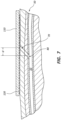
- FIG. 3 provides a side view of the radial artery compression device 100.
- FIG. 4 provides a side view of the radial artery compression device 100 with an inflatable chamber 126 in an inflated state.
- FIG. 5 provides a side view of the radial artery compression device 100 on a wrist of a patient 50 with the inflatable chamber 126 in an inflated state.
- the radial artery compression device 100 includes a substantially rigid frame 110, a flexible sheet 120, and a wristband 130.
- the substantially rigid frame 110 includes an outer surface 111 and an inner surface 113.
- the substantially rigid frame 100 is contoured to curve around a thumb-side portion of the wrist of the patient 50.
- the substantially rigid frame 110 includes a curved section 112 (see FIGS. 3-5 ).
- the frame 110 is shaped as a curved (e.g., arched) sheet.
- the outer surface 111 of the frame 110 (or a portion thereof) may be convex, while the inner surface 113 of the frame 110 (or a portion thereof) may be concave.
- the substantially rigid frame 110 further includes a substantially straight section 114 configured to be disposed adjacent an underside (i.e., a palmar side) of a wrist of the patient 50.
- the substantially rigid frame 110 (or a portion thereof) is transparent.
- the curved section 112 may have a radius of curvature (r) of between 1.5 cm and 2.5 cm (see FIG. 3 ). Additionally or alternatively, the degree measure ( ⁇ ) of an arc formed by the curved section 112 may be between 45 and 100 degrees. For example, in some embodiments, the curved section 112 is between 80 and 95 degrees (e.g., approximately 90 degrees).
- the flexible sheet 120 is coupled to the frame 110.
- the flexible sheet 120 includes a peripheral portion 122 that is attached to the frame 110 and a central portion 114 that is not attached to the frame 110.
- the peripheral portion 122 of the flexible sheet 120 is attached to the frame 110 via welding or an adhesive.
- the flexible sheet 120 may be made from any suitable material, such as polyurethane or PVC.
- the material of the flexible sheet is stretchable.
- the flexible sheet is substantially rectangular in shape, although other shapes are also within the scope of this disclosure.
- the flexible sheet 120 (or a portion thereof) is transparent.
- both the substantially rigid frame 110 (or a portion thereof) and the flexible sheet 120 (or a portion thereof) are transparent, thereby allowing a practitioner to view a radial access site through the frame 110 and the flexible sheet 120.
- the practitioner may need to view through only two layers (e.g., the frame 110 and the flexible sheet 120) to view the radial access site. Viewing through only two layers may provide improved visual clarity relative to embodiments in which the radial access site is viewed through more than two layers or parts.
- the wristband 130 is coupled to the frame 110.
- the wristband 130 may include a first strap that is attached to one side of the frame 110 and a second strap that is attached to an opposite side of the frame 110.
- the wristband 130 may be configured to secure the frame 110 adjacent to the wrist of the patient 50.
- the entire wristband 130 (or a portion thereof) is opaque.
- the wristband 130 is colored and/or decorated.
- the wristband 130 includes hook and loop fasteners (e.g., Velcro).
- the wristband 130 is an integrated Velcro strap.
- other attachment means are used to secure the radial artery compression device 100 to the arm of the patient 50.
- the substantially rigid frame 110 and the flexible sheet 120 may form the inflatable chamber 126.
- the inner surface 113 of the frame 110 and the flexible sheet 120 at least partially define the inflatable chamber 126.
- a wall of the inflatable chamber 126 may be defined by the frame 110.
- the inflatable chamber 126 may be defined by both a first portion (e.g., the substantially rigid frame 110) of the radial artery compression device 100 that does not change size or shape as the inflatable chamber 126 is inflated and a second portion (e.g., the flexible sheet 120) of the radial artery compression device 100 that does change in size or shape as the inflatable chamber 126 is inflated.
- the inflatable chamber 126 When the wristband 130 is secured to the wrist of the patient 50, the inflatable chamber 126 may be positioned adjacent to a radial artery 10 of the patient (see FIG. 5 ).
- the radial artery compression device 100 includes only a single inflatable chamber 126.
- the use of the single inflatable chamber 126 may provide one or more advantages relative to radial artery compression devices that employ multiple inflatable chambers, such as ease of construction and/or ease of use.
- the maximum capacity of the inflatable chamber is between 3 mL and 30 mL.
- the maximum capacity of the inflatable chamber 126 is between 3 mL and 12 mL, between 3 mL and 20 mL, between 3 mL and 25 mL, between 5 mL and 15 mL, between 10 mL and 20 mL, between 10 mL and 30 mL, or between 15 mL and 30 mL.
- the inflatable chamber 126 may be configured for applying varying amounts of pressure to a radial access site of the patient 50.
- the inflatable chamber 126 provides pressure to the radial access site in a manner that avoids restricting the ulnar artery.
- the radial artery compression device 100 includes tubing 135 that extends from a first aperture 116 (see FIG. 5 ) in the substantially rigid frame 110 to a valve 140.
- the tubing 135 and the valve 140 may be in fluid communication with the inflatable chamber 126 that is formed by the substantially rigid frame 110 and the flexible sheet 120.
- the valve 140 is configured to allow fluid to flow through the valve 140 when the valve 140 is coupled to an inflation device (e.g., a syringe), but prevents fluid flow through the valve 140 when the valve 140 is not coupled (i.e., detached from) the inflation device.
- the valve 140 may maintain a positive fluid pressure within the inflatable chamber 126 after the inflation device has been uncoupled from the valve 140.
- the tubing 135 is coupled to the frame 110 via a connector 150 that protrudes from the outer surface 111 of the frame 110.
- the tubing 135 extends from the connector 150 for a length of 5 cm to 15 cm, 6 cm to 15 cm, 8 cm to 15 cm, 10 cm to 15 cm, 12 cm to 15 cm, 6 cm to 12 cm, 6 cm to 10 cm, 6 cm to 8 cm, or 8 cm to 10 cm in length.
- the tubing 135 is between about 5 cm to about 15 cm. In other embodiments, no tubing 135 is used. In other embodiments, the tubing 135 is of some other length.
- the radial artery compression device 100 may further include a retainer 160 (e.g., a clip) that is configured to secure a free end of the tubing 135 to the frame 110.
- a retainer 160 e.g., a clip
- the retainer 160 may be positioned (1) ulnar or radial of the connector 150 and/or (2) proximal or distal of the connector 150.
- the retainer 160 is positioned radial of and distal of the connector 150.
- the retainer 160 and the connector 150 may be positioned at a distance from one another such that, when a proximal end of the tubing 135 is attached to the retainer 160, only a small length of the tubing 135 protrudes from the radial artery compression device 100, thereby minimizing the bulk of the radial artery compression device 100.
- FIGS. 6 and 7 show one way of positioning the radial artery compression device 100 relative to a puncture site 70 and an arteriotomy site 80. More particularly, FIG. 6 shows the radial artery compression device 100 secured to the wrist of the patient 50 at a particular location relative to the puncture site 70, while FIG. 7 provides a cross-sectional view of the through plane 7-7 of FIG. 6 .
- the elongate device When an elongate device, such as a needle, sheath, or catheter, is introduced into the radial artery 10 for an interventional procedure, the elongate device may be inserted at an angle such that the location where the elongate device passes through the skin (i.e., the puncture site) is not directly above the location where the elongate device passes through the artery wall (i.e., the arteriotomy site).
- the puncture site may be separated from the arteriotomy site by a distance (d).
- the distance (d) is approximately 1-10 mm, 2-5 mm, and/or 3-4 mm.
- the radial artery compression device 100 includes indicia on the frame 110.
- the indicia on the frame 110 are designed to facilitate identification of the arteriotomy site 80 relative to the visible puncture site 70 in the skin of the patient 50.
- a first indicium 115a is disposed on the frame 110.
- the first indicium 115a is located at the intersection of a T-shaped mark on the frame 110.
- a second indicium 117 is disposed directly over the (non-visible) arteriotomy site 80.
- the second indicium 117 is the center of a target-shaped mark on the frame 110.
- the second indicium 117 is disposed directly above a center of the flexible sheet 120.
- the second indicium 117 is disposed directly over a region of the inflatable chamber 126 that is designed to extend furthest from the frame 110 when the inflatable chamber 126 is in an inflated state.
- the radial artery compression device 100 may additionally or alternatively include an indicium 115b.
- the indicium 115b may be aligned with a puncture site when the radial artery compression device 100 is placed on the left hand of the patient 50.
- the radial artery compression device 100 may include indicia to facilitate alignment with the puncture site 70 regardless of the arm on which the radial artery compression device 100 is placed.
- indicia that differ in some ways from the indicia shown in FIG. 6 may be used for analogous purposes. In other words, various forms of indicia may be used to facilitate proper alignment of the radial artery compression device 100.
- the radial artery compression device 100 may include one or more of the following components: a pressure sensor, a timer, an alarm, a control unit, a power source, a wireless connection, and a display 180. In some embodiments, one or more of these components are enclosed within and/or supported by a housing 170.
- the housing 170 may be fixedly or detachably coupled to the frame 110. For example, in the depicted embodiment, the housing 170 is fixedly coupled to and extends from the frame 110.
- the housing 170 and/or one or more components disposed therein may be reprocessed and/or refurbished for further use.
- the pressure sensor may be in fluid communication with the inflatable chamber 126.
- the pressure sensor may be in fluid communication with the inflatable chamber 126 through a second aperture (not shown) in the substantially rigid frame 110.
- the pressure within the inflatable chamber 126 may inform protocols for use of the radial artery compression device 100.
- pressure measurements obtained by the pressure sensor may be relayed to the display 180. The practitioner may use the pressure information on the display to increase or decrease the amount of fluid within the inflatable chamber 126 as desired.
- the pressure sensor is detachable from the remaining portions of the radial artery compression device 100.
- the pressure transducer is not detachable from the radial artery compression device 100.
- some radial artery compression devices include a timer.
- the timer is a countdown timer.
- the timer is a stopwatch (i.e., count-up) timer.
- the timer may be configured to measure time from some reference period, such as when an actuator (e.g., a button or pull tab) is actuated.
- time is measured from when the radial artery compression device 100 is positioned on the arm of the patient 50 and initially inflated.
- the timer may additionally or alternatively measure time from when fluid is initially removed from the inflatable chamber 126 during deflation.
- the timer may be configured to measure the amount of time that the inflatable chamber 126 has remained at a particular pressure.
- the timer may be in communication with the display 180.
- the display 180 shows the amount of elapsed time in minutes and seconds.
- the display may show the amount of elapsed time in hours and minutes.
- the display may transition from displaying minutes and seconds to displaying hours and minutes once the amount of elapsed time reaches one hour.
- the timer is detachable from the remaining portions of the radial artery compression device 100. In other embodiments, the timer is not detachable.
- the radial artery compression device 100 includes an alarm.
- the alarm may be a visible alarm (e.g., the flashing of light-emitting diodes). In other or further embodiments, the alarm may be audible.
- the alarm may alert the patient 50 and/or the practitioner to certain information (e.g., the length of the time that the radial artery compression device 100 has remained in a particular state). Based on this information, the practitioner and/or the patient 50 may make any needed changes.
- the radial artery compression device 100 may include a wireless connection (e.g., via Bluetooth or Wi-Fi). Information from the radial artery compression device 100 (e.g., information relating to pressure or elapsed time) may be wirelessly transmitted to one of more other devices to alert a medical practitioner of treatment needs, such as the need to modify the amount of pressure provided to the radial artery at a particular time.
- a wireless connection e.g., via Bluetooth or Wi-Fi
- Information from the radial artery compression device 100 e.g., information relating to pressure or elapsed time
- Information from the radial artery compression device 100 may be wirelessly transmitted to one of more other devices to alert a medical practitioner of treatment needs, such as the need to modify the amount of pressure provided to the radial artery at a particular time.
- the radial artery compression device 100 may be used at or near the conclusion of a medical procedure to facilitate hemostasis of the radial artery 10.
- the radial artery compression device 100 may be secured to the wrist of the patient 50, such as via the wristband 130.
- the practitioner may secure the radial artery compression device 100 to the wrist of the patient 50 such that the inflatable chamber 126 of the radial artery compression device 100 is positioned adjacent to a radial access site.
- the radial artery compression device 100 is placed on the wrist around a portion of an elongate medical instrument that accesses the radial artery of the patient 50 through a radial access site.
- the practitioner may align the first indicium 115a on the frame 110 of the radial artery compression device 100 with the puncture site 70 in the skin of the patient 50.
- the practitioner may view the radial access site through the frame 110 and the flexible sheet 120 and align the first indicium 115a on the frame 110 with the puncture site 70.
- the inflatable chamber 126 of the radial artery compression device 100 may be positioned to provide compression to the arteriotomy site 80 that is upstream of the puncture site 70.
- the inflatable chamber 126 is positioned directly over an arteriotomy site of the patient 50.
- the second indicium 117 is disposed directly over the arteriotomy site 80 when the first indicium 115a is aligned with the puncture site 70.
- the inflatable chamber 126 may be inflated in any suitable manner.
- the practitioner may connect an inflation device (e.g., a syringe) to the valve 140. Connecting the inflation device to the valve 140 may open the valve 140, allowing the practitioner to deliver fluid into the inflatable chamber 126.
- a practitioner may advance a plunger of a syringe that is connected to the valve 140, causing fluid to pass through the valve 140, the tubing 135, and the first aperture 116 to enter into the inflatable chamber 126.
- the delivery of fluid to the inflatable chamber 126 may cause the inflatable chamber 126 to expand, thereby increasing the amount of pressure that is applied to the radial access site. Stated differently, inflating the inflatable chamber 126 may increase pressure that is applied to the radial access site.
- the inflatable chamber 126 may first be partially inflated to provide some compression force to the radial access site. With the inflatable chamber 126 in a partially inflated state, an elongate medical device that is partially inserted into the radial artery may be withdrawn from the radial artery such that no medical device extends through the puncture site 70 of the skin of the patient 50 to the arteriotomy site 80.
- fluid may then be delivered to the inflatable chamber 126 in an amount that is sufficient to stop bleeding at the arteriotomy site 80.
- sufficient fluid may be provided to fully inflate the inflatable chamber 126.
- fluid within the inflatable chamber 126 may be slowly withdrawn until a flash of blood is visible at the skin puncture site 70 through the frame 110 and the flexible sheet 120.
- additional fluid e.g., 1-2 mL
- This process may provide adequate pressure to achieve hemostasis while maintaining patency of the radial artery 10.
- this protocol can be used to ensure that sufficient pressure is provided to prevent bleeding, while avoiding the application of excessive force (which can unduly restrict blood flow through the radial artery 10).
- the practitioner may deflate the inflatable chamber 126 over a series of stages. Such deflation may follow a particular predetermined protocol. For example, in some embodiments, after the radial artery compression device 100 has been used to apply a compressive force for some period of time (e.g., 5 minutes to 5 hours), a predetermined volume (e.g., 0.5 mL to 3 mL) of fluid may be removed every 2-3 minutes until all of the air is removed. Provided that the removal of compression force does not result in further bleeding, the radial artery compression device 100 may then be removed from the patient 50. In other words, once compression is no longer needed to ensure hemostasis, the radial artery compression device 100 may be removed from the patient 50.
- a predetermined volume e.g., 0.5 mL to 3 mL
- fluid may be removed from the inflatable chamber 126 based on information provided by the radial artery compression device 100.
- the inflatable chamber 126 may be deflated based on information obtained from a timer or an alarm of the radial artery compression device 100.
- the radial artery compression device may count the amount of time that has elapsed since the radial artery compression device 100 was placed on the patient 50 and alert the practitioner of the proper time to begin removing fluid from the inflatable chamber 126.
- the timer may be activated by an actuator, such as a button or a pull tab. In some embodiments, the timer may count up. In other or further embodiments, the timer may count down.
- the radial artery compression device 100 may also indicate the timing for staged deflation.
- the practitioner or the patient 50 is alerted to the need to remove fluid based on a visible indicator (e.g., information provided on the display 180).
- the information from the visible indicator may be provided on the display 180, via lights (e.g., light-emitting diodes), or in some other manner.
- the practitioner or the patient 50 is alerted to the need to remove fluid based on one or more sounds (e.g., the sounds of an audible alarm) that are emitted from the radial artery compression device 100.
- lights e.g., LEDs
- other indicia inform the practitioner of the stage of deflation.
- lights may be used to indicate the number of times fluid has been removed from the inflatable chamber 126.
- the radial artery compression device 100 may be powered by any suitable power source.
- the radial artery compression device 100 includes a battery 195 that is disposed within the housing 170.
- the battery 195 may provide power to a pressure sensor, a timer, an alarm, and/or the display 180.
- the radial artery compression device 100 is configured to facilitate removal of the battery from the housing.
- the radial artery compression device 100 may include a battery latch 190 that is rotatably coupled to the housing 170.
- the battery latch 190 may be opened as shown in FIG. 8 to remove the battery 195 from the radial artery compression device 100.
- the radial artery compression device 100 may be configured to facilitate removal of one or more batteries 195 for the housing 170. Facile removal of the battery 195 may allow the radial artery compression device 100 to be discarded separate from battery waste.
- FIG. 9 provides a perspective view of a radial artery compression device 200 that includes a solar panel 292 that is supported by a housing 270.
- the radial artery compression device 200 may use solar energy to power components such as a pressure sensor, a timer, an alarm, lights, and/or a display.
- some radial artery compression devices may be powered by a slow-discharge capacitor. The use of a slow-discharge capacitor may allow the radial artery compression device to be discarded without concern for battery waste.
- the radial artery compression device may not include a power source within the housing.
- FIG. 10 provides a perspective view of another radial artery compression device 300.
- the radial artery compression device 300 is generally analogous to the radial artery compression devices 100, 200 described above. However, in the embodiment shown in FIG. 10 , the connector 350 and the retainer 360 are positioned in different locations when compared to the connectors and retainers shown in FIGS. 1-9 .
- the connector 350 is both proximal and radial of the retainer 360.
- Tubing 335 may initially extend radially from the connector 350 and then bend such that a valve 340 at the free end of the tubing is disposed ulnar of the connector 350.
- the retainer 360 may secure the tubing 335 adjacent to the remaining portions of the radial artery compression device 300.
- Some radial artery compression devices described herein, such as radial artery compression devices 100, 200, and 300 may be placed on either arm of the patient 50.
- the radial artery compression device 100 is shown in FIG. 1 on the right arm of the patient 50, the radial artery compression device 100 may alternatively be used on the left arm of the patient 50.
- the frame 110 may be contoured to curve around a thumb-side portion of the left wrist of the patient 50.
- the radial artery compression device 100 of FIGS. 1-8 may be rotated such that the connector 150 is both ulnar of and distal of the retainer 160.
- some compression devices may, additionally or alternatively, be suitable for compression of an ulnar artery.
- a compression device may be placed on the patient such that the frame curves around the ulnar side of the wrist.
- the inflatable chamber may be positioned adjacent to the ulnar artery such that inflation of the inflatable chamber applies pressure to an access site in the ulnar artery.
- some compression devices described herein may be used to promote healing at access sites in an ulnar artery.
- Any methods disclosed herein include one or more steps or actions for performing the described method.
- the method steps and/or actions may be interchanged with one another.
- the order and/or use of specific steps and/or actions may be modified.
- sub-routines or only a portion of a method described herein may be a separate method within the scope of this disclosure. Stated otherwise, some methods may include only a portion of the steps described in a more detailed method.
Description
- The present disclosure relates generally to the field of medical devices. More particularly, some embodiments relate to compression devices, including radial artery compression devices with an inflatable chamber.
The prior art documentsUS2012/245675 A1 ,WO2012/126154 A1 ,US 2015/018869 A1 andUS 2015/327871 disclose devices for applying targeted force to a radial access puncture site to aid in arresting bleeding at the puncture site. The devices disclosed comprise a band for placing the device at a patient's wrist, and an inflatable balloon attached to the band and disposed over the puncture site during use. The inflated balloon applies pressure to the puncture site. The devices further comprise targeting indicia disposed, e.g. on the balloon and/or on the rigid or semirigid member, e.g. a backing layer of the balloon. The targeting indicia serve to identify that portion of the balloon to be positioned on the puncture site so that the inflated balloon applies pressure on that site during use. - The written disclosure herein describes illustrative embodiments that are nonlimiting and non-exhaustive. Reference is made to certain of such illustrative embodiments that are depicted in the figures, in which:
-
FIG. 1 depicts a radial artery compression device that is secured to a wrist of a patient. -
FIG. 2 is a perspective view of an underside of the radial artery compression device ofFIG. 1 . -
FIG. 3 is a side view of the radial artery compression device ofFIGS. 1-2 with the inflatable chamber in an uninflated state. -
FIG. 4 is a side view of a portion of the radial artery compression device ofFIGS. 1-3 with the inflatable chamber in a fully inflated state. -
FIG. 5 is a cross-sectional side view of the radial artery compression device ofFIGS. 1-4 around the wrist of a patient with the inflatable chamber in a fully inflated state. -
FIG. 6 is a perspective view of the radial artery compression device ofFIGS. 1-5 showing the relative positioning of indicia to a puncture site and an arteriotomy site. -
FIG. 7 is a cross-sectional view of the radial artery compression device ofFIGS. 1-6 showing a puncture site and an arteriotomy site. -
FIG. 8 is a perspective view of the radial artery compression device ofFIGS. 1-7 showing a battery removal mechanism. -
FIG. 9 is a perspective view of a solar-powered radial artery compression device. -
FIG. 10 is a perspective view of another embodiment of a radial artery compression device. - The radial artery compression device comprises a substantially rigid frame, the frame comprising an outer surface and an inner surface, wherein at least a portion of the frame is transparent, a flexible sheet that is coupled to the frame, wherein at least a portion of the sheet is transparent, and an inflatable chamber that is at least partially defined by the inner surface of the frame and the flexible sheet.
- In the radial artery compression device the flexible sheet comprises a peripheral portion that is attached to the frame and a central portion that is not attached to the frame.
- In some embodiments of the radial artery compression device the radial artery compression device further comprises a wristband that is configured to secure the frame to a wrist of a patient such that the inflatable chamber is positioned adjacent to the radial artery.
- In some embodiments of the radial artery compression device, the frame is contoured to curve around a thumb-side portion of a wrist.
- In some embodiments of the radial artery compression device the radial artery compression device further comprises a valve that is in fluid communication with the inflatable chamber.
- In some embodiments of the radial artery compression device, the valve is configured to (1) allow fluid to flow through the valve when the valve is coupled to an inflation device and (2) prevent fluid flow through the valve when the valve is not coupled to the inflation device.
- In some embodiments of the radial artery compression device, the valve is in fluid communication with the inflation chamber via tubing that extends from a first aperture in the rigid member to the valve.
- In some embodiments of the radial artery compression device, the tubing is coupled to the frame via a connector that protrudes from the outer surface of the frame.
- In some embodiments of the radial artery compression device the radial artery compression device further comprises a retainer that is configured to secure a free end of the tubing to the frame.
- In some embodiments of the radial artery compression device, the retainer is positioned both (1) ulnar or radial of and (2) either proximal or distal of the connector when the radial artery compression device is coupled to the wrist of a patient.
- In some embodiments of the radial artery compression device, the tubing is between 5 and 15 cm in length.
- In some embodiments of the radial artery compression device, the radial artery compression device further comprises a timer.
- In some embodiments of the radial artery compression device, the radial artery compression device further comprises an alarm.
- In some embodiments of the radial artery compression device, the radial artery compression device further comprises a pressure sensor that is in fluid communication with the inflatable chamber.
- In the radial artery compression device, the radial artery compression device further comprises indicia on the frame, wherein the indicia are designed to facilitate identification of an arteriotomy site relative to a puncture site in the patient's skin.
- In the radial artery compression device, the radial artery compression device comprises: a substantially rigid frame, a wristband for securing the substantially rigid frame adjacent to a wrist of a patient, an inflatable chamber for applying pressure to a radial access site of a patient and a first indicium disposed on the substantially rigid frame, wherein at least a portion of the substantially rigid frame and at least a portion of the inflatable chamber are transparent and, wherein the radial artery compression device is configured such that alignment of a first indicium with a puncture site in the patient's skin positions the inflatable chamber directly over an arteriotomy site of the patient.
- In the radial artery compression device, the radial artery compression device further comprises a second indicium disposed on the substantially rigid frame, wherein the second indicium is disposed directly over the arteriotomy site when the first indicium is aligned with the puncture site.
- In some embodiments of the radial artery compression device, a wall of the inflatable chamber is defined by the frame.
- In some embodiments of a method for achieving hemostasis at an access site of a radial artery, the method comprises: providing a radial artery compression device, the device comprising: an inflatable chamber, a substantially rigid frame and a wristband, securing the radial artery compression device to a wrist of a patient such that the inflatable chamber of the radial artery compression device is positioned adjacent to the access site of the radial artery and inflating the inflatable chamber to increase pressure that is applied to the access site,wherein the access site is visible through the frame and the inflatable chamber.
- In some embodiments of the method a wall of the inflatable chamber is defined by the frame.
- In some embodiments of the method, the method further comprises aligning a first indicium on the frame with a puncture site in the patient's skin.
- In some embodiments of the method, the method further comprises removing air from the inflatable chamber over a plurality of stages according to a predetermined protocol.
- In some embodiments of the method, the method further comprises removing air from the inflatable chamber based on information obtained from a timer of the radial artery compression device.
- In some embodiments of the method, the method further comprises removing air from the inflatable chamber based on information obtained from one or more light-emitting diodes.
- In some embodiments of the method, the method further comprises removing air from the inflatable chamber based on one or more sounds emitted from the radial artery compression device.
- Numerous medical procedures involve insertion of one or more elongate medical devices into the vasculature of a patient. Some of these interventional procedures involve delivery of a medical device through a radial artery of the patient.
- Achieving hemostasis during and/or after an interventional procedure that involves puncturing the radial artery may present certain challenges.
- To facilitate hemostasis at the radial access site, pressure may be applied slightly upstream of the skin puncture site. Such pressure may prevent or reduce the leakage of blood from the arteriotomy site and promote hemostasis. Certain embodiments described herein facilitate the application of pressure to promote hemostasis at a radial access site.
- The components of the embodiments as generally described and illustrated in the figures herein can be arranged and designed in a wide variety of different configurations. Thus, the following more detailed description of various embodiments, as represented in the figures, is not intended to limit the scope of the present disclosure, but is merely representative of various embodiments. While various aspects of the embodiments are presented in drawings, the drawings are not necessarily drawn to scale unless specifically indicated.
- The phrase "coupled to" is broad enough to refer to any suitable coupling or other form of interaction between two or more entities. Thus, two components may be coupled to each other even though they are not in direct contact with each other. For example, two components may be coupled to one another through an intermediate component. The phrase "attached to" refers to interactions between two or more entities which are in direct contact with each other and/or are separated from each other only by a fastener of any suitable variety (e.g., an adhesive). The phrase "fluid communication" is used in its ordinary sense, and is broad enough to refer to arrangements in which a fluid (e.g., a gas or a liquid) can flow from one element to another element when the elements are in fluid communication with each other.
- The terms "proximal" and "distal" are opposite directional terms. For example, the distal end of a radial artery compression device or a component thereof is the end that is furthest from the attachment point of the arm of the patient during ordinary use of the device. The proximal end refers to the opposite end, or the end nearest the patient during ordinary use. When used as a directional term, the term "radial" refers to the direction pointing from the center of the arm or hand to the thumb-side portion of the arm or hand. The term "ulnar" refers to the opposite direction. The particular volumes recited herein refer to the volumes of fluid that are delivered from a syringe that holds the recited amount of fluid at atmospheric pressure. For example, an inflatable chamber has a capacity of 15 mL if it is capable of receiving 15 mL of air from a syringe that holds 15 mL of air at atmospheric pressure.
-
FIGS. 1-5 provide alternative views of a radialartery compression device 100. More particularly,FIG. 1 depicts a radialartery compression device 100 secured to the wrist of apatient 50.FIG. 2 provides a perspective view of an underside of the radialartery compression device 100.FIG. 3 provides a side view of the radialartery compression device 100.FIG. 4 provides a side view of the radialartery compression device 100 with aninflatable chamber 126 in an inflated state. AndFIG. 5 provides a side view of the radialartery compression device 100 on a wrist of a patient 50 with theinflatable chamber 126 in an inflated state. - As shown in
FIGS. 1-5 , the radialartery compression device 100 includes a substantiallyrigid frame 110, aflexible sheet 120, and awristband 130. - The substantially
rigid frame 110 includes anouter surface 111 and aninner surface 113. In some embodiments, the substantiallyrigid frame 100 is contoured to curve around a thumb-side portion of the wrist of thepatient 50. For example, in some embodiments, the substantiallyrigid frame 110 includes a curved section 112 (seeFIGS. 3-5 ). In the embodiment shown inFIGS. 1-5 , theframe 110 is shaped as a curved (e.g., arched) sheet. Theouter surface 111 of the frame 110 (or a portion thereof) may be convex, while theinner surface 113 of the frame 110 (or a portion thereof) may be concave. In some embodiments, the substantiallyrigid frame 110 further includes a substantiallystraight section 114 configured to be disposed adjacent an underside (i.e., a palmar side) of a wrist of thepatient 50. In some embodiments, the substantially rigid frame 110 (or a portion thereof) is transparent. - In some embodiments, the
curved section 112 may have a radius of curvature (r) of between 1.5 cm and 2.5 cm (seeFIG. 3 ). Additionally or alternatively, the degree measure (θ) of an arc formed by thecurved section 112 may be between 45 and 100 degrees. For example, in some embodiments, thecurved section 112 is between 80 and 95 degrees (e.g., approximately 90 degrees). - The
flexible sheet 120 is coupled to theframe 110. For example, in some embodiments, theflexible sheet 120 includes aperipheral portion 122 that is attached to theframe 110 and acentral portion 114 that is not attached to theframe 110. In some embodiments, theperipheral portion 122 of theflexible sheet 120 is attached to theframe 110 via welding or an adhesive. Theflexible sheet 120 may be made from any suitable material, such as polyurethane or PVC. In some embodiments, the material of the flexible sheet is stretchable. In the depicted embodiment, the flexible sheet is substantially rectangular in shape, although other shapes are also within the scope of this disclosure. The flexible sheet 120 (or a portion thereof) is transparent. For example, in some embodiments, both the substantially rigid frame 110 (or a portion thereof) and the flexible sheet 120 (or a portion thereof) are transparent, thereby allowing a practitioner to view a radial access site through theframe 110 and theflexible sheet 120. In some embodiments, the practitioner may need to view through only two layers (e.g., theframe 110 and the flexible sheet 120) to view the radial access site. Viewing through only two layers may provide improved visual clarity relative to embodiments in which the radial access site is viewed through more than two layers or parts. - The
wristband 130 is coupled to theframe 110. For example, thewristband 130 may include a first strap that is attached to one side of theframe 110 and a second strap that is attached to an opposite side of theframe 110. Thewristband 130 may be configured to secure theframe 110 adjacent to the wrist of thepatient 50. In some embodiments, the entire wristband 130 (or a portion thereof) is opaque. In some embodiments, thewristband 130 is colored and/or decorated. In some embodiments, thewristband 130 includes hook and loop fasteners (e.g., Velcro). For example, in some embodiments, thewristband 130 is an integrated Velcro strap. In other embodiments, other attachment means are used to secure the radialartery compression device 100 to the arm of thepatient 50. - The substantially
rigid frame 110 and theflexible sheet 120 may form theinflatable chamber 126. According to the claimed invention, theinner surface 113 of theframe 110 and theflexible sheet 120 at least partially define theinflatable chamber 126. Stated differently, a wall of theinflatable chamber 126 may be defined by theframe 110. In this fashion, theinflatable chamber 126 may be defined by both a first portion (e.g., the substantially rigid frame 110) of the radialartery compression device 100 that does not change size or shape as theinflatable chamber 126 is inflated and a second portion (e.g., the flexible sheet 120) of the radialartery compression device 100 that does change in size or shape as theinflatable chamber 126 is inflated. - When the
wristband 130 is secured to the wrist of thepatient 50, theinflatable chamber 126 may be positioned adjacent to aradial artery 10 of the patient (seeFIG. 5 ). In some embodiments, the radialartery compression device 100 includes only a singleinflatable chamber 126. The use of the singleinflatable chamber 126 may provide one or more advantages relative to radial artery compression devices that employ multiple inflatable chambers, such as ease of construction and/or ease of use. In some embodiments, the maximum capacity of the inflatable chamber is between 3 mL and 30 mL. For example, in some embodiments, the maximum capacity of theinflatable chamber 126 is between 3 mL and 12 mL, between 3 mL and 20 mL, between 3 mL and 25 mL, between 5 mL and 15 mL, between 10 mL and 20 mL, between 10 mL and 30 mL, or between 15 mL and 30 mL. Theinflatable chamber 126 may be configured for applying varying amounts of pressure to a radial access site of thepatient 50. In some embodiments, theinflatable chamber 126 provides pressure to the radial access site in a manner that avoids restricting the ulnar artery. - In some embodiments, the radial
artery compression device 100 includestubing 135 that extends from a first aperture 116 (seeFIG. 5 ) in the substantiallyrigid frame 110 to avalve 140. Thetubing 135 and thevalve 140 may be in fluid communication with theinflatable chamber 126 that is formed by the substantiallyrigid frame 110 and theflexible sheet 120. In some embodiments, thevalve 140 is configured to allow fluid to flow through thevalve 140 when thevalve 140 is coupled to an inflation device (e.g., a syringe), but prevents fluid flow through thevalve 140 when thevalve 140 is not coupled (i.e., detached from) the inflation device. In other words, thevalve 140 may maintain a positive fluid pressure within theinflatable chamber 126 after the inflation device has been uncoupled from thevalve 140. - In the depicted embodiment, the
tubing 135 is coupled to theframe 110 via aconnector 150 that protrudes from theouter surface 111 of theframe 110. In some embodiments, thetubing 135 extends from theconnector 150 for a length of 5 cm to 15 cm, 6 cm to 15 cm, 8 cm to 15 cm, 10 cm to 15 cm, 12 cm to 15 cm, 6 cm to 12 cm, 6 cm to 10 cm, 6 cm to 8 cm, or 8 cm to 10 cm in length. In other words, in some embodiments, thetubing 135 is between about 5 cm to about 15 cm. In other embodiments, notubing 135 is used. In other embodiments, thetubing 135 is of some other length. - In some embodiments, the radial
artery compression device 100 may further include a retainer 160 (e.g., a clip) that is configured to secure a free end of thetubing 135 to theframe 110. In some embodiments, when the radialartery compression device 100 is secured to the right arm of thepatient 50, theretainer 160 may be positioned (1) ulnar or radial of theconnector 150 and/or (2) proximal or distal of theconnector 150. For example, when the depicted embodiment is secured to the right arm of the patient 50 as shown inFIG. 1 , theretainer 160 is positioned radial of and distal of theconnector 150. Theretainer 160 and theconnector 150 may be positioned at a distance from one another such that, when a proximal end of thetubing 135 is attached to theretainer 160, only a small length of thetubing 135 protrudes from the radialartery compression device 100, thereby minimizing the bulk of the radialartery compression device 100. -
FIGS. 6 and7 show one way of positioning the radialartery compression device 100 relative to apuncture site 70 and anarteriotomy site 80. More particularly,FIG. 6 shows the radialartery compression device 100 secured to the wrist of the patient 50 at a particular location relative to thepuncture site 70, whileFIG. 7 provides a cross-sectional view of the through plane 7-7 ofFIG. 6 . - When an elongate device, such as a needle, sheath, or catheter, is introduced into the
radial artery 10 for an interventional procedure, the elongate device may be inserted at an angle such that the location where the elongate device passes through the skin (i.e., the puncture site) is not directly above the location where the elongate device passes through the artery wall (i.e., the arteriotomy site). In other words, the puncture site may be separated from the arteriotomy site by a distance (d). In some embodiments, the distance (d) is approximately 1-10 mm, 2-5 mm, and/or 3-4 mm. - In some circumstances, it may be advantageous to focus compression on the
arteriotomy site 80 rather than thepuncture site 70. In other words, hemostasis may be more rapidly and effectively achieved by applying a compression force to thearteriotomy site 80 in a relatively direct manner. To assist a practitioner in placing the radialartery compression device 100 at a location that provides appropriate compression to thearteriotomy site 80, the radialartery compression device 100 includes indicia on theframe 110. The indicia on theframe 110 are designed to facilitate identification of thearteriotomy site 80 relative to thevisible puncture site 70 in the skin of thepatient 50. - According to the invention, a
first indicium 115a is disposed on theframe 110. In the depicted embodiment, thefirst indicium 115a is located at the intersection of a T-shaped mark on theframe 110. When thefirst indicium 115a is aligned with thepuncture site 70 that is visible through thetransparent frame 110 and the transparentflexible sheet 120, asecond indicium 117 is disposed directly over the (non-visible)arteriotomy site 80. In the depicted embodiment, thesecond indicium 117 is the center of a target-shaped mark on theframe 110. Thesecond indicium 117 is disposed directly above a center of theflexible sheet 120. According to the invention, thesecond indicium 117 is disposed directly over a region of theinflatable chamber 126 that is designed to extend furthest from theframe 110 when theinflatable chamber 126 is in an inflated state. - In some embodiments, the radial
artery compression device 100 may additionally or alternatively include anindicium 115b. Theindicium 115b may be aligned with a puncture site when the radialartery compression device 100 is placed on the left hand of thepatient 50. Stated differently, in some embodiments, the radialartery compression device 100 may include indicia to facilitate alignment with thepuncture site 70 regardless of the arm on which the radialartery compression device 100 is placed. One of ordinary skill in the art will recognize that indicia that differ in some ways from the indicia shown inFIG. 6 may be used for analogous purposes. In other words, various forms of indicia may be used to facilitate proper alignment of the radialartery compression device 100. - In some embodiments, the radial
artery compression device 100 may include one or more of the following components: a pressure sensor, a timer, an alarm, a control unit, a power source, a wireless connection, and adisplay 180. In some embodiments, one or more of these components are enclosed within and/or supported by ahousing 170. Thehousing 170 may be fixedly or detachably coupled to theframe 110. For example, in the depicted embodiment, thehousing 170 is fixedly coupled to and extends from theframe 110. In embodiments in which thehousing 170 is detachably coupled to the frame, thehousing 170 and/or one or more components disposed therein (e.g., a pressure sensor, a timer, an alarm, a control unit, a power source, a wireless connection, or a display 180) may be reprocessed and/or refurbished for further use. - In some embodiments that include a pressure sensor or pressure transducer (not shown), the pressure sensor may be in fluid communication with the
inflatable chamber 126. For example, the pressure sensor may be in fluid communication with theinflatable chamber 126 through a second aperture (not shown) in the substantiallyrigid frame 110. The pressure within theinflatable chamber 126, as measured by the pressure sensor, may inform protocols for use of the radialartery compression device 100. For example, pressure measurements obtained by the pressure sensor may be relayed to thedisplay 180. The practitioner may use the pressure information on the display to increase or decrease the amount of fluid within theinflatable chamber 126 as desired. In some embodiments, the pressure sensor is detachable from the remaining portions of the radialartery compression device 100. In other embodiments, the pressure transducer is not detachable from the radialartery compression device 100. - As noted above, some radial artery compression devices include a timer. In some embodiments, the timer is a countdown timer. In other or further embodiments, the timer is a stopwatch (i.e., count-up) timer. The timer may be configured to measure time from some reference period, such as when an actuator (e.g., a button or pull tab) is actuated. In some embodiments, time is measured from when the radial
artery compression device 100 is positioned on the arm of thepatient 50 and initially inflated. The timer may additionally or alternatively measure time from when fluid is initially removed from theinflatable chamber 126 during deflation. In some embodiments, the timer may be configured to measure the amount of time that theinflatable chamber 126 has remained at a particular pressure. - In some instances, the timer may be in communication with the
display 180. In some embodiments, thedisplay 180 shows the amount of elapsed time in minutes and seconds. In other or further embodiments, the display may show the amount of elapsed time in hours and minutes. In some embodiments, the display may transition from displaying minutes and seconds to displaying hours and minutes once the amount of elapsed time reaches one hour. In some embodiments, the timer is detachable from the remaining portions of the radialartery compression device 100. In other embodiments, the timer is not detachable. - In some embodiments, the radial
artery compression device 100 includes an alarm. In some cases, the alarm may be a visible alarm (e.g., the flashing of light-emitting diodes). In other or further embodiments, the alarm may be audible. The alarm may alert the patient 50 and/or the practitioner to certain information (e.g., the length of the time that the radialartery compression device 100 has remained in a particular state). Based on this information, the practitioner and/or the patient 50 may make any needed changes. - In some embodiments, the radial
artery compression device 100 may include a wireless connection (e.g., via Bluetooth or Wi-Fi). Information from the radial artery compression device 100 (e.g., information relating to pressure or elapsed time) may be wirelessly transmitted to one of more other devices to alert a medical practitioner of treatment needs, such as the need to modify the amount of pressure provided to the radial artery at a particular time. - The radial
artery compression device 100 may be used at or near the conclusion of a medical procedure to facilitate hemostasis of theradial artery 10. For example, in some procedures, the radialartery compression device 100 may be secured to the wrist of thepatient 50, such as via thewristband 130. The practitioner may secure the radialartery compression device 100 to the wrist of the patient 50 such that theinflatable chamber 126 of the radialartery compression device 100 is positioned adjacent to a radial access site. For example, in some embodiments, the radialartery compression device 100 is placed on the wrist around a portion of an elongate medical instrument that accesses the radial artery of the patient 50 through a radial access site. - In some circumstances, the practitioner may align the
first indicium 115a on theframe 110 of the radialartery compression device 100 with thepuncture site 70 in the skin of thepatient 50. For example, the practitioner may view the radial access site through theframe 110 and theflexible sheet 120 and align thefirst indicium 115a on theframe 110 with thepuncture site 70. When thefirst indicium 115a is aligned with thepuncture site 70, theinflatable chamber 126 of the radialartery compression device 100 may be positioned to provide compression to thearteriotomy site 80 that is upstream of thepuncture site 70. Stated differently, when thefirst indicium 115a of the radialartery compression device 100 is aligned with thepuncture site 70 in the skin of thepatient 50, theinflatable chamber 126 is positioned directly over an arteriotomy site of thepatient 50. According to the invention, thesecond indicium 117 is disposed directly over thearteriotomy site 80 when thefirst indicium 115a is aligned with thepuncture site 70. - Once the radial
artery compression device 100 is properly placed on the arm of thepatient 50, theinflatable chamber 126 may be inflated in any suitable manner. For example, in some embodiments, the practitioner may connect an inflation device (e.g., a syringe) to thevalve 140. Connecting the inflation device to thevalve 140 may open thevalve 140, allowing the practitioner to deliver fluid into theinflatable chamber 126. For example, a practitioner may advance a plunger of a syringe that is connected to thevalve 140, causing fluid to pass through thevalve 140, thetubing 135, and thefirst aperture 116 to enter into theinflatable chamber 126. The delivery of fluid to theinflatable chamber 126 may cause theinflatable chamber 126 to expand, thereby increasing the amount of pressure that is applied to the radial access site. Stated differently, inflating theinflatable chamber 126 may increase pressure that is applied to the radial access site. - In some circumstances, the
inflatable chamber 126 may first be partially inflated to provide some compression force to the radial access site. With theinflatable chamber 126 in a partially inflated state, an elongate medical device that is partially inserted into the radial artery may be withdrawn from the radial artery such that no medical device extends through thepuncture site 70 of the skin of the patient 50 to thearteriotomy site 80. - After the elongate medical device has been removed, fluid may then be delivered to the
inflatable chamber 126 in an amount that is sufficient to stop bleeding at thearteriotomy site 80. For example, in some embodiments, sufficient fluid may be provided to fully inflate theinflatable chamber 126. Once enough fluid has been delivered to theinflatable chamber 126 to stop the bleeding, fluid within theinflatable chamber 126 may be slowly withdrawn until a flash of blood is visible at theskin puncture site 70 through theframe 110 and theflexible sheet 120. At this stage, additional fluid (e.g., 1-2 mL) may be injected back into theinflatable chamber 126 to stop the bleeding. This process may provide adequate pressure to achieve hemostasis while maintaining patency of theradial artery 10. In other words, this protocol can be used to ensure that sufficient pressure is provided to prevent bleeding, while avoiding the application of excessive force (which can unduly restrict blood flow through the radial artery 10). - As the
arteriotomy site 80 and/or thepuncture site 70 begin to heal, the amount of compression needed to maintain hemostasis may decrease. Accordingly, the practitioner may deflate theinflatable chamber 126 over a series of stages. Such deflation may follow a particular predetermined protocol. For example, in some embodiments, after the radialartery compression device 100 has been used to apply a compressive force for some period of time (e.g., 5 minutes to 5 hours), a predetermined volume (e.g., 0.5 mL to 3 mL) of fluid may be removed every 2-3 minutes until all of the air is removed. Provided that the removal of compression force does not result in further bleeding, the radialartery compression device 100 may then be removed from thepatient 50. In other words, once compression is no longer needed to ensure hemostasis, the radialartery compression device 100 may be removed from thepatient 50. - In some instances, fluid may be removed from the
inflatable chamber 126 based on information provided by the radialartery compression device 100. For example, in some embodiments, theinflatable chamber 126 may be deflated based on information obtained from a timer or an alarm of the radialartery compression device 100. For example, the radial artery compression device may count the amount of time that has elapsed since the radialartery compression device 100 was placed on thepatient 50 and alert the practitioner of the proper time to begin removing fluid from theinflatable chamber 126. The timer may be activated by an actuator, such as a button or a pull tab. In some embodiments, the timer may count up. In other or further embodiments, the timer may count down. The radialartery compression device 100 may also indicate the timing for staged deflation. In some instances, the practitioner or thepatient 50 is alerted to the need to remove fluid based on a visible indicator (e.g., information provided on the display 180). The information from the visible indicator may be provided on thedisplay 180, via lights (e.g., light-emitting diodes), or in some other manner. In other or further embodiments, the practitioner or thepatient 50 is alerted to the need to remove fluid based on one or more sounds (e.g., the sounds of an audible alarm) that are emitted from the radialartery compression device 100. In some embodiments, lights (e.g., LEDs) or other indicia inform the practitioner of the stage of deflation. For example, in some embodiments, lights may be used to indicate the number of times fluid has been removed from theinflatable chamber 126. - The radial
artery compression device 100 may be powered by any suitable power source. For example, in the embodiment depicted inFIGS. 1-8 , the radialartery compression device 100 includes abattery 195 that is disposed within thehousing 170. Thebattery 195 may provide power to a pressure sensor, a timer, an alarm, and/or thedisplay 180. In some embodiments, the radialartery compression device 100 is configured to facilitate removal of the battery from the housing. For example, the radialartery compression device 100 may include abattery latch 190 that is rotatably coupled to thehousing 170. Thebattery latch 190 may be opened as shown inFIG. 8 to remove thebattery 195 from the radialartery compression device 100. In other words, the radialartery compression device 100 may be configured to facilitate removal of one ormore batteries 195 for thehousing 170. Facile removal of thebattery 195 may allow the radialartery compression device 100 to be discarded separate from battery waste. - Radial artery compression devices need not be powered by one or more batteries. For example,
FIG. 9 provides a perspective view of a radialartery compression device 200 that includes asolar panel 292 that is supported by ahousing 270. The radialartery compression device 200 may use solar energy to power components such as a pressure sensor, a timer, an alarm, lights, and/or a display. Alternatively, some radial artery compression devices may be powered by a slow-discharge capacitor. The use of a slow-discharge capacitor may allow the radial artery compression device to be discarded without concern for battery waste. In still other embodiments (e.g., embodiments lacking components such as a pressure sensor, a timer, an alarm, lights, and a display), the radial artery compression device may not include a power source within the housing. -
FIG. 10 provides a perspective view of another radialartery compression device 300. The radialartery compression device 300 is generally analogous to the radialartery compression devices FIG. 10 , theconnector 350 and theretainer 360 are positioned in different locations when compared to the connectors and retainers shown inFIGS. 1-9 . - When the radial
artery compression device 300 is disposed on the right wrist of a patient for placement over a radial artery, theconnector 350 is both proximal and radial of theretainer 360.Tubing 335 may initially extend radially from theconnector 350 and then bend such that avalve 340 at the free end of the tubing is disposed ulnar of theconnector 350. Theretainer 360 may secure thetubing 335 adjacent to the remaining portions of the radialartery compression device 300. - Some radial artery compression devices described herein, such as radial
artery compression devices patient 50. For example, while the radialartery compression device 100 is shown inFIG. 1 on the right arm of thepatient 50, the radialartery compression device 100 may alternatively be used on the left arm of thepatient 50. When the radialartery compression device 100 is disposed on the left arm of thepatient 50, theframe 110 may be contoured to curve around a thumb-side portion of the left wrist of thepatient 50. Stated differently, when the radialartery compression device 100 ofFIG. 1 is properly placed on the left arm of thepatient 50, the radialartery compression device 100 ofFIGS. 1-8 may be rotated such that theconnector 150 is both ulnar of and distal of theretainer 160. - While the compression devices described above are described as radial artery compression devices, some compression devices may, additionally or alternatively, be suitable for compression of an ulnar artery. For example, a compression device may be placed on the patient such that the frame curves around the ulnar side of the wrist. When placed on the patient in this manner, the inflatable chamber may be positioned adjacent to the ulnar artery such that inflation of the inflatable chamber applies pressure to an access site in the ulnar artery. Thus, some compression devices described herein may be used to promote healing at access sites in an ulnar artery.
- Any methods disclosed herein include one or more steps or actions for performing the described method. The method steps and/or actions may be interchanged with one another. In other words, unless a specific order of steps or actions is required for proper operation of the embodiment, the order and/or use of specific steps and/or actions may be modified. Moreover, sub-routines or only a portion of a method described herein may be a separate method within the scope of this disclosure. Stated otherwise, some methods may include only a portion of the steps described in a more detailed method.
- Reference throughout this specification to "an embodiment" or "the embodiment" means that a particular feature, structure, or characteristic described in connection with that embodiment is included in at least one embodiment. Thus, the quoted phrases, or variations thereof, as recited throughout this specification are not necessarily all referring to the same embodiment.
- Similarly, it should be appreciated by one of skill in the art with the benefit of this disclosure that in the above description of embodiments, various features are sometimes grouped together in a single embodiment, figure, or description thereof for the purpose of streamlining the disclosure. This method of disclosure, however, is not to be interpreted as reflecting an intention that any claim requires more features than those expressly recited in that claim. Rather, as the following claims reflect, inventive aspects lie in a combination of fewer than all features of any single foregoing disclosed embodiment. Thus, the claims following this Detailed Description are hereby expressly incorporated into this Detailed Description, with each claim standing on its own as a separate embodiment. This disclosure includes all permutations of the independent claims with their dependent claims.
- Recitation in the claims of the term "first" with respect to a feature or element does not necessarily imply the existence of a second or additional such feature or element. It will be apparent to those having skill in the art that changes may be made to the details of the above-described embodiments without departing from the underlying principles of the present disclosure.
Claims (14)
- A radial artery compression device (100), the device comprising:a rigid frame (110), the frame (110) comprising an outer surface (111) and an inner surface (113), wherein at least a portion of the frame (110) is transparent;a flexible sheet (120) that is coupled to the frame (110), wherein at least a portion of the sheet (120) is transparent; andan inflatable chamber (126) that is at least partially defined by the inner surface (113) of the frame (110) and the flexible sheet (120); andcharacterized in thatthe radial artery compression device (100) comprises indicia on the transparent portion of the frame (110) with a first indicium (115a) positioned directly on the transparent portion of the frame (110) and a second indicium (117) positioned directly on the transparent portion of the frame (110), the second indicium (117) is axially offset from the first indicium (115a), andwherein the indicia are designed to facilitate identification of an arteriotomy site (80) relative to a puncture site (70) in the patient's skin, such that aligning a first indicium with the puncture site (70) on the patient's skin is configured to position a center of the flexible sheet (120) that is designed to extend furthest from the frame (110) when the inflatable chamber (126) is in an inflated state, directly over the arteriotomy site (80).
- The radial artery compression device of claim 1, wherein the flexible sheet (120) comprises a peripheral portion (122) that is attached to the frame (110) and a central portion (114) that is not attached to the frame (110).
- The radial artery compression device of any one of claims 1-2, further comprising a wristband (130) that is configured to secure the frame (110) to a wrist of a patient (50) such that the inflatable chamber (126) is positioned adjacent to the radial artery (10).
- The radial artery compression device of any one of claims 1-3, wherein the frame (110) is contoured to curve around a thumb-side portion of a wrist.
- The radial artery compression device of any one of claims 1-4, further comprising a valve (140) that is in fluid communication with the inflatable chamber (126).
- The radial artery compression device of claim 5, wherein the valve (140) is configured to (1) allow fluid to flow through the valve (140) when the valve (140) is coupled to an inflation device and (2) prevent fluid flow through the valve (140) when the valve (140) is not coupled to the inflation device.
- The radial artery compression device of any one of claims 5-6, wherein the valve (140) is in fluid communication with the inflation chamber (126) via tubing (135) that extends from a first aperture (116) in the rigid member to the valve (140).
- The radial artery compression device of claim 7, wherein the tubing (135) is coupled to the frame (110) via a connector (150) that protrudes from the outer surface (111) of the frame (110).
- The radial artery compression device of claim 8, further comprising a retainer (160) that is configured to secure a free end of the tubing (135) to the frame (110).
- The radial artery compression device of claim 9, wherein the retainer (160) is positioned both (1) ulnar or radial of and (2) either proximal or distal of the connector (150) when the radial artery compression device (100) is coupled to the wrist of a patient (50).
- The radial artery compression device of claim 8, wherein the tubing (135) is between 5 and 15 cm in length.
- The radial artery compression device of any one of claims 1-11, further comprising a timer.
- The radial artery compression device of any one of claims 1-12, further comprising an alarm.
- The radial artery compression device of any one of claims 1-13, further comprising a pressure sensor that is in fluid communication with the inflatable chamber (126).
Applications Claiming Priority (2)
| Application Number | Priority Date | Filing Date | Title |
|---|---|---|---|
| US201662363695P | 2016-07-18 | 2016-07-18 | |
| PCT/US2017/041726 WO2018017365A1 (en) | 2016-07-18 | 2017-07-12 | Inflatable radial artery compression device |
Publications (3)
| Publication Number | Publication Date |
|---|---|
| EP3484559A1 EP3484559A1 (en) | 2019-05-22 |
| EP3484559A4 EP3484559A4 (en) | 2020-03-11 |
| EP3484559B1 true EP3484559B1 (en) | 2023-08-23 |
Family
ID=60941804
Family Applications (1)
| Application Number | Title | Priority Date | Filing Date |
|---|---|---|---|
| EP17831575.0A Active EP3484559B1 (en) | 2016-07-18 | 2017-07-12 | Inflatable radial artery compression device |
Country Status (6)
| Country | Link |
|---|---|
| US (2) | US10702281B2 (en) |
| EP (1) | EP3484559B1 (en) |
| JP (1) | JP7066642B2 (en) |
| AU (1) | AU2017299466B2 (en) |
| CA (1) | CA3027665A1 (en) |
| WO (1) | WO2018017365A1 (en) |
Families Citing this family (15)
| Publication number | Priority date | Publication date | Assignee | Title |
|---|---|---|---|---|
| JP7066642B2 (en) | 2016-07-18 | 2022-05-13 | メリット・メディカル・システムズ・インコーポレイテッド | Inflatable radial artery compression device |
| JP7458319B2 (en) | 2017-11-03 | 2024-03-29 | メリット・メディカル・システムズ・インコーポレイテッド | Hemostatic devices and methods of use |
| JP2021515654A (en) * | 2018-03-09 | 2021-06-24 | メリット・メディカル・システムズ・インコーポレイテッドMerit Medical Systems,Inc. | Ultrasound-compatible inflatable vascular compression and related systems and methods |
| US10702282B2 (en) * | 2018-03-29 | 2020-07-07 | Ring Rescue Incorporated | Devices and methods for compressing a digit to facilitate removal of a ring |
| CN108451571A (en) * | 2018-04-10 | 2018-08-28 | 南京市妇幼保健院 | A kind of Allen experiments pressurizer |
| EP3773257A4 (en) * | 2018-04-11 | 2021-12-22 | Merit Medical Systems, Inc. | Inflatable compression device |
| USD911516S1 (en) * | 2018-06-19 | 2021-02-23 | Merit Medical Systems, Inc. | Hemostasis device |
| US20200289129A1 (en) * | 2019-03-14 | 2020-09-17 | Medtronic Vascular, Inc. | Tissue compression device |
| CN109745095A (en) * | 2019-03-15 | 2019-05-14 | 柳州市柳铁中心医院 | A kind of novel arteria radialis compressing device |
| EP3979925A4 (en) * | 2019-06-09 | 2023-06-14 | Merit Medical Systems, Inc. | Fluid delivery adapter for vascular compression devices and associated methods |
| CN111166422A (en) * | 2020-01-08 | 2020-05-19 | 成都体育学院附属体育医院 | Improved tourniquet |
| JP7304486B2 (en) * | 2020-03-27 | 2023-07-06 | テルモ株式会社 | compression device |
| JPWO2022239827A1 (en) * | 2021-05-14 | 2022-11-17 | ||
| US20230012280A1 (en) * | 2021-07-06 | 2023-01-12 | Terumo Medical Corporation | Monitoring system for a hemostasis band |
| US20230255640A1 (en) * | 2022-02-11 | 2023-08-17 | Merit Medical Systems, Inc. | Inflatable radial artery compression device with reinforced backer plate |
Family Cites Families (666)
| Publication number | Priority date | Publication date | Assignee | Title |
|---|---|---|---|---|
| US44843A (en) | 1864-10-25 | Improvement in injectors for the hair | ||
| US11623A (en) | 1854-08-29 | Breast-cup | ||
| US2547A (en) | 1842-04-11 | Edward | ||
| US1177208A (en) | 1915-06-15 | 1916-03-28 | Juriah Harris Pierpont | Pulmotor. |
| US1197232A (en) | 1916-05-03 | 1916-09-05 | Juriah Harris Pierpont | Pulmotor. |
| US1281653A (en) | 1917-10-06 | 1918-10-15 | Henry W Plummer | Tourniquet. |
| US2332107A (en) | 1941-02-27 | 1943-10-19 | Nieburgs Haims Eguda | Surgical tourniquet |
| US2397257A (en) | 1943-02-04 | 1946-03-26 | Philip P Goland | Surgical suction apparatus |
| US3003500A (en) | 1955-12-14 | 1961-10-10 | Baxter Laboratories Inc | Intravenous administration equipment |
| US3021841A (en) | 1957-03-14 | 1962-02-20 | Baxter Laboratories Inc | Intravenous administration equipment |
| US3050064A (en) | 1959-10-22 | 1962-08-21 | Robert E Moore | Mechanical compress bandage |
| US3115138A (en) | 1960-07-14 | 1963-12-24 | Mcelvenny | Evacuator |
| US3058627A (en) | 1961-04-27 | 1962-10-16 | C B Fischbach | Combined suction pump, storage container and dispenser |
| GB1010067A (en) | 1962-05-28 | 1965-11-17 | Stanley Charles Wade | Improvements relating to the control of fluids |
| DE1251906B (en) | 1963-06-21 | 1900-01-01 | ||
| US3253594A (en) | 1963-07-30 | 1966-05-31 | Frank E Matthews | Peritoneal cannula |
| GB1095316A (en) | 1963-08-08 | 1967-12-13 | Arthur Bane | Improvements in ampoules for surgical hypodermic syringes |
| US3376846A (en) | 1963-08-10 | 1968-04-09 | Victor Company Of Japan | Indicating apparatus |
| US3241554A (en) | 1963-08-14 | 1966-03-22 | Baxter Don Inc | Peritoneal dialysis entry device |
| US3312221A (en) | 1963-10-25 | 1967-04-04 | Alfred P H Overment | Urinary drainage apparatus |
| GB1052614A (en) | 1964-06-04 | |||
| US3319684A (en) | 1964-11-30 | 1967-05-16 | Pharmaseal Lab | Collapsible container |
| US3459189A (en) | 1965-07-28 | 1969-08-05 | Brunswick Corp | Trocar catheter |
| US3417750A (en) | 1965-10-22 | 1968-12-24 | Bard Inc C R | Aspirating means and one-way valve |
| US3419010A (en) | 1966-01-17 | 1968-12-31 | Cordis Corp | Catheter |
| US3363626A (en) | 1966-03-17 | 1968-01-16 | J A Deknatel Inc | Underwater drainage apparatus |
| US3487837A (en) | 1967-02-06 | 1970-01-06 | Roy A Petersen | Device for holding catheters in position |
| US3572340A (en) | 1968-01-11 | 1971-03-23 | Kendall & Co | Suction drainage device |
| US3542026A (en) | 1968-07-23 | 1970-11-24 | Billy M Bledsoe | Thoracostomy device |
| US3554580A (en) | 1968-12-02 | 1971-01-12 | Baxter Laboratories Inc | Catheter adapter and process and assembly for its securance |
| SE344361B (en) | 1969-03-14 | 1972-04-10 | C Nyberg | |
| US3566875A (en) | 1969-05-20 | 1971-03-02 | Richard K Stoehr | Device for draining cerebrospinal fluid |
| US3960153A (en) | 1969-09-30 | 1976-06-01 | Jane Towne Carey | Apparatus for the palliative treatment of pleural effusions |
| US3820546A (en) | 1970-08-26 | 1974-06-28 | Abbott Lab | Combined air vent,filter and adapter for urinary drainage assemblies |
| US3752158A (en) | 1970-11-23 | 1973-08-14 | Snyder Manuf Co Inc | Apparatus and method for suprapubic drainage of the urinary bladder |
| US3683929A (en) | 1970-12-28 | 1972-08-15 | Extracorporeal Med Spec | Device for draining cerebrospinal fluid in cases of hydrocephalus |
| US3777757A (en) | 1971-01-08 | 1973-12-11 | R Gray | Sucking wound plug and chest aspirator |
| US3680562A (en) | 1971-04-26 | 1972-08-01 | Becton Dickinson Co | Surgical drainage apparatus for bladder |
| US3742952A (en) | 1971-04-28 | 1973-07-03 | Alpha Ind Inc | Surgical suction pump assembly |
| US3783870A (en) | 1971-12-27 | 1974-01-08 | Sherwood Medical Ind Inc | Suction drainage device |
| US3768476A (en) | 1972-01-27 | 1973-10-30 | Concord Labor Inc | Urinary irrigation and drainage system |
| US3774611A (en) | 1972-06-08 | 1973-11-27 | J Tussey | Stabilized contamination free surgical evacuator |
| US3853127A (en) | 1973-04-03 | 1974-12-10 | R Spademan | Elastic sealing member |
| US3809087A (en) | 1973-05-17 | 1974-05-07 | R Lewis | Closed wound suction apparatus having biased plate members |
| US4022209A (en) | 1973-11-19 | 1977-05-10 | International Paper Company | Resilient self-contained fluid evacuator |
| US3920023A (en) | 1974-03-21 | 1975-11-18 | Kendall & Co | Method and apparatus for placement of a suprapubic catheter |
| US3875941A (en) | 1974-04-03 | 1975-04-08 | Medical Dynamics Inc | System for evacuating fluids from the body |
| ES208987Y (en) | 1975-01-10 | 1976-08-16 | Baya Pena | DEVICE FOR CLEANING AND DISINFECTING THE NASAL FOSES. |
| US3982546A (en) | 1975-02-28 | 1976-09-28 | Friend John H | Device for draining a body cavity |
| ZA762197B (en) | 1975-04-15 | 1977-04-27 | Int Paper Co | Fluid evacuator |
| US4014011A (en) | 1975-04-25 | 1977-03-22 | Hewlett-Packard Company | Variable resolution display |
| US4073294A (en) | 1975-07-23 | 1978-02-14 | Medical Development Corporation | Negative pressure drainage vessel |
| US4105031A (en) | 1975-10-10 | 1978-08-08 | Deknatel, Inc. | Attachable expansion chamber for pleural drainage device |
| US4174053A (en) | 1976-03-15 | 1979-11-13 | Zojirushi Vacuume Bottle Co., Ltd. | Vacuum bottle having a tilt responsive closure |
| GB1596496A (en) | 1976-07-06 | 1981-08-26 | Matburn Holdings Ltd | Filter for a colostomy or ileostomy appliance and a method of manufacture therefor |
| JPS5318851A (en) | 1976-08-05 | 1978-02-21 | Zojirushi Vacuum Bottle Co | Electric airpot |
| US4112949A (en) | 1976-11-15 | 1978-09-12 | Howmedica Inc. | Apparatus for collecting body fluid |
| US4153058A (en) | 1977-07-05 | 1979-05-08 | Nehme Alexander E | Pleural decompression catheter |
| US4143853A (en) | 1977-07-14 | 1979-03-13 | Metatech Corporation | Valve for use with a catheter or the like |
| US4187848A (en) | 1977-07-18 | 1980-02-12 | The Kendall Company | Adapter assembly |
| US4170300A (en) | 1978-01-18 | 1979-10-09 | The Purdue Frederick Company | Dressing change kits |
| US4382442A (en) | 1978-04-24 | 1983-05-10 | Jones James W | Thoracostomy pump-tube apparatus |
| US4257629A (en) | 1978-05-01 | 1981-03-24 | Rain Bird Sprinkler Mfg. Corp. | Flexible conduit repair coupling |
| US4390519A (en) | 1978-05-19 | 1983-06-28 | Sawyer Philip Nicholas | Bandage with hemostatic agent and methods for preparing and employing the same |
| DE2837813C3 (en) | 1978-08-30 | 1981-08-20 | Willy Rüsch GmbH & Co KG, 7053 Kernen | Method of making a medical tube or catheter |
| US4214593A (en) | 1978-09-18 | 1980-07-29 | Mallinckrodt, Inc. | Esophageal pressure monitoring device |
| US4203445A (en) | 1978-12-11 | 1980-05-20 | Hollister Incorporated | Gas-venting filter assembly for collection device |
| US4266545A (en) | 1979-04-06 | 1981-05-12 | Moss James P | Portable suction device for collecting fluids from a closed wound |
| US4334551A (en) | 1979-04-30 | 1982-06-15 | Becton Dickinson & Company | Connector |
| US4620846A (en) | 1979-06-04 | 1986-11-04 | Goldberg Edward M | Apparatus and method for introducing fluid into and removing fluid from a living subject |
| US4310104A (en) | 1979-09-04 | 1982-01-12 | Zojirushi Vacuum Bottle Co., Ltd. | Vacuum bottle with bellows pump |
| US4307799A (en) | 1979-12-05 | 1981-12-29 | Andco Actuator Products, Inc. | Linear actuator |
| JPS56126026A (en) | 1980-03-05 | 1981-10-02 | Hideo Inui | Bending method and its die device |
| US4393873A (en) | 1980-03-10 | 1983-07-19 | Nawash Michael S | Gastrostomy and other percutaneous transport tubes |
| US4315513A (en) | 1980-03-10 | 1982-02-16 | Nawash Michael S | Gastrostomy and other percutaneous transport tubes |
| FR2479014A1 (en) | 1980-03-31 | 1981-10-02 | Matburn Holdings Ltd | SURGICAL DRAINAGE BAGS |
| US4738671A (en) | 1980-06-06 | 1988-04-19 | C. R. Bard, Inc. | Chest drainage apparatus with check valve |
| US4747844A (en) | 1980-06-06 | 1988-05-31 | C. R. Bard, Inc. | Chest drainage apparatus |
| US4341212A (en) | 1980-07-18 | 1982-07-27 | Albert Medwid | Serous fluid drain kit |
| US4404924A (en) | 1980-09-05 | 1983-09-20 | Uresil Company | Body fluid suction device indicators |
| US4429693A (en) | 1980-09-16 | 1984-02-07 | Blake L W | Surgical fluid evacuator |
| USD267433S (en) | 1980-09-26 | 1982-12-28 | C. R. Bard, Inc. | Chest drainage bottle |
| JPS57140136A (en) | 1981-02-25 | 1982-08-30 | Sumitomo Bakelite Co Ltd | Production of reticulated thermoplastic resin article |
| US4681571A (en) | 1981-04-23 | 1987-07-21 | C. R. Bard, Inc. | Suction canister with disposable liner and check valve |
| US4439190A (en) | 1981-04-27 | 1984-03-27 | Chesebrough-Pond's Inc. | Underwater drainage device |
| DK153813C (en) | 1981-05-07 | 1989-02-06 | Matburn Holdings Ltd | STOMA BAG |
| US4447235A (en) | 1981-05-07 | 1984-05-08 | John M. Clarke | Thoracentesis device |
| USD267815S (en) | 1981-05-26 | 1983-02-01 | C. R. Bard Inc. | Chest drainage bottle |
| SE455470B (en) | 1981-06-23 | 1988-07-18 | Terumo Corp | CONNECTING TWO HOSE FOR MEDICAL, THERAPEUTICAL USE HOSE |
| NZ200936A (en) | 1981-06-24 | 1985-05-31 | Johnson & Johnson | Vacuum drainage bottle;pressure indicator operable prior to connecting bottle to wound drainage tube |
| US4364395A (en) | 1981-06-30 | 1982-12-21 | American Heyer-Schulte Corporation | Low profile shunt system |
| US4464168A (en) | 1981-06-30 | 1984-08-07 | American Hospital Supply Corporation | Low profile shunt system |
| US4392858A (en) | 1981-07-16 | 1983-07-12 | Sherwood Medical Company | Wound drainage device |
| US4512771A (en) | 1981-10-06 | 1985-04-23 | C. R. Bard, Inc. | Venting assembly for a sealed body fluid drainage device |
| US4445551A (en) | 1981-11-09 | 1984-05-01 | Bond Curtis J | Quick-disconnect coupling and valve assembly |
| GB2109239B (en) | 1981-11-13 | 1985-07-10 | Howard Charles Baron | Anatomical compression device |
| US4402682A (en) | 1981-12-02 | 1983-09-06 | Garver Sr Edward B | Tamper-proof cannula support assembly |
| US4396382A (en) | 1981-12-07 | 1983-08-02 | Travenol European Research And Development Centre | Multiple chamber system for peritoneal dialysis |
| US4490003A (en) | 1982-01-11 | 1984-12-25 | C. R. Bard, Inc. | Electrical connector |
| US4433973A (en) | 1982-01-12 | 1984-02-28 | Bioresearch Inc. | Reusable tube connector assembly |
| DE3218561C2 (en) | 1982-05-17 | 1988-08-18 | Günter H. Dr.-Ing. 8035 Gauting Marx | Device for taking up and reinfusing blood |
| US4455141A (en) | 1982-06-08 | 1984-06-19 | Todd Edward P | Drainage apparatus with vacuum control |
| US4511163A (en) | 1982-07-14 | 1985-04-16 | Mead Johnson & Company | Adaptable tip tubing connector |
| US4569674A (en) | 1982-08-03 | 1986-02-11 | Stryker Corporation | Continuous vacuum wound drainage system |
| US4476866A (en) | 1982-08-06 | 1984-10-16 | Thomas J. Fogarty | Combined large and small bore syringe |
| US4479495A (en) | 1982-09-27 | 1984-10-30 | Isaacson Gary S | Acupressure point stimulator device |
| US4475904A (en) | 1982-12-29 | 1984-10-09 | Medical Instrument Dev. Labs., Inc. | Fast response vacuum aspiration collection system |
| US4752292A (en) | 1983-01-24 | 1988-06-21 | Icu Medical, Inc. | Medical connector |
| NL8300386A (en) | 1983-02-02 | 1984-09-03 | Steritech Bv | STERILE DEVICE CONNECTING TWO ROOMS. |
| US4539985A (en) | 1983-06-03 | 1985-09-10 | Magrath Joseph M | Aspirator and resuscitator for newborn animals |
| FR2551978B1 (en) | 1983-09-15 | 1988-12-16 | Archeny Jean Pierre | INTRA-UTERINE PROBE FOR HYSTEROGRAPHY AND MEASUREMENT OF PUMP PERMEABILITY |
| US4496464A (en) | 1983-10-03 | 1985-01-29 | Hensley Clifford J | Filter apparatus and method |
| US4501363A (en) | 1983-10-25 | 1985-02-26 | Isbey Jr Edward K | Surgical kit |
| US4543100A (en) | 1983-11-01 | 1985-09-24 | Brodsky Stuart A | Catheter and drain tube retainer |
| JPS60111175A (en) | 1983-11-21 | 1985-06-17 | Osaka Gas Co Ltd | Detecting method of pipe |
| US4557262A (en) | 1984-02-15 | 1985-12-10 | Snow Kenneth T | Dialysis clamp |
| US4669463A (en) | 1984-02-22 | 1987-06-02 | Mcconnell Richard B | Endotracheal tube injection site addition |
| US4741678A (en) | 1984-03-07 | 1988-05-03 | C. R. Bard, Inc. | Pulsatile pump |
| US4605400A (en) | 1984-05-04 | 1986-08-12 | Bioresearch Inc. | Surgical drainage apparatus |
| US4583972A (en) | 1984-05-18 | 1986-04-22 | Complex, Inc. | Wound evacuator |
| US4564222A (en) | 1984-08-27 | 1986-01-14 | Hydrasearch Co., Inc. | Separable coupling for thin-walled flexible hose |
| US4740202A (en) | 1984-10-12 | 1988-04-26 | Haemonetics Corporation | Suction collection device |
| US4685908A (en) | 1984-10-18 | 1987-08-11 | Bioresearch Ithaca Inc. | Device for detecting increased pressure in pleural cavity |
| US4685901A (en) | 1984-11-05 | 1987-08-11 | Medical Innovations Corporation | Gastro-jejunal feeding device |
| US4701163A (en) | 1984-11-05 | 1987-10-20 | Medical Innovations Corporation | Gastrostomy feeding device |
| US4666433A (en) | 1984-11-05 | 1987-05-19 | Medical Innovations Corporation | Gastrostomy feeding device |
| US4610671A (en) | 1985-03-28 | 1986-09-09 | Luther Medical Products, Inc. | Assembly of stylet and catheter |
| DE3676769D1 (en) | 1985-07-31 | 1991-02-14 | Kawasumi Lab Inc | COUPLING FOR PLASMAPHERESIS BAG. |
| US4929235A (en) | 1985-07-31 | 1990-05-29 | Universal Medical Instrument Corp. | Self-sealing percutaneous tube introducer |
| CA1280326C (en) | 1985-09-25 | 1991-02-19 | Leif Joakim Sundblom | Fast response tubeless vacuum aspiration collection cassette |
| US4675020A (en) | 1985-10-09 | 1987-06-23 | Kendall Mcgaw Laboratories, Inc. | Connector |
| US5061255A (en) | 1985-10-15 | 1991-10-29 | Albert Greenfeld | Exterior antimigration refinements for self-cleaning indwelling therapeutic articles |
| US4863593A (en) | 1985-10-29 | 1989-09-05 | The University Of Akron | Battery powered vacuum unit |
| US4702733A (en) | 1985-11-22 | 1987-10-27 | Innovative Surgical Products, Inc. | Foot actuated pinch valve and high vacuum source for irrigation/aspiration handpiece system |
| US4673398A (en) | 1985-12-16 | 1987-06-16 | Turner Kenneth R | Suction device for use with tracheostomy tube |
| US4643720A (en) | 1986-02-14 | 1987-02-17 | Medi-Tech | Drainage catheter |
| EP0245211A1 (en) | 1986-03-04 | 1987-11-11 | HOECHST ITALIA SUD S.p.A. | Kidney-ureter catheter unit particularly adapated to evacuate crumbled calculi |
| JPH0244854Y2 (en) | 1986-03-29 | 1990-11-28 | ||
| US4747843A (en) | 1986-05-15 | 1988-05-31 | C.R. Bard, Inc. | Control module for thoracic drainage apparatus |
| DK156028C (en) | 1986-05-16 | 1989-11-06 | Testa Lab A S | ASPIRATOR |
| US4883474A (en) | 1986-07-30 | 1989-11-28 | David S. Sheridan | Thoracic catheter |
| JPH0745542B2 (en) | 1986-10-02 | 1995-05-17 | チッソ株式会社 | Method for producing catalyst component for olefin polymerization |
| US4809679A (en) | 1986-11-19 | 1989-03-07 | Olympus Optical Co., Ltd. | Forceps plug for endoscopes |
| US4850955A (en) | 1986-12-02 | 1989-07-25 | Codman & Shurtleff | Body fluid transfer device |
| US5102404A (en) | 1986-12-15 | 1992-04-07 | Uresil Corporation | Apparatus and method for collecting body fluids |
| US5019059A (en) | 1986-12-15 | 1991-05-28 | Uresil Corporation | Apparatus and method for collecting body fluids |
| US4946449A (en) | 1986-12-18 | 1990-08-07 | Davis Jr Richard C | Indwelling urethral catheter system and method |
| JPS63164935A (en) | 1986-12-27 | 1988-07-08 | 株式会社東芝 | Suction apparatus of endoscope |
| US4781674A (en) | 1987-01-30 | 1988-11-01 | Vir Engineering | Fluid flow control valve |
| US4813929A (en) | 1987-02-19 | 1989-03-21 | Neal Semrad | Chest tube device and method of inserting device |
| US5251873B1 (en) | 1992-06-04 | 1995-05-02 | Vernay Laboratories | Medical coupling site. |
| US5295658A (en) | 1987-04-27 | 1994-03-22 | Vernay Laboratories, Inc. | Medical coupling site including slit reinforcing members |
| US5002529A (en) | 1987-07-10 | 1991-03-26 | Solco Basle, Inc. | Postoperative wound drainage |
| JPH088933B2 (en) | 1987-07-10 | 1996-01-31 | 日本ゼオン株式会社 | Catheter |
| US5165953A (en) | 1990-06-12 | 1992-11-24 | Robin Renee Thill Shlenker | Method of forming a membrane, especially a latex membrane, having a biocide barrier |
| US4834802A (en) | 1987-08-06 | 1989-05-30 | Prier David A | Heat generating tourniquet for venipuncture applications |
| US4930997A (en) | 1987-08-19 | 1990-06-05 | Bennett Alan N | Portable medical suction device |
| US4828546A (en) | 1987-08-21 | 1989-05-09 | Surgidyne, Inc. | Bulb evacuator for closed wound suction |
| US4949756A (en) | 1988-08-31 | 1990-08-21 | Uresil Corporation | One-way valve |
| US4844087A (en) | 1987-09-16 | 1989-07-04 | Garg Rakesh K | First method for using cannula including a valve structure and associated instrument element |
| US4966197A (en) | 1987-09-16 | 1990-10-30 | Uresil Corporation | One-way valve |
| US5078677A (en) | 1987-09-29 | 1992-01-07 | Conmed Corporation | Apparatus for collecting blood from a chest drainage unit and reinfusion of the blood |
| US4883476A (en) | 1988-01-07 | 1989-11-28 | Bioresearch, Inc. | Drainage device with disposable collection chamber |
| US4921488A (en) | 1988-01-15 | 1990-05-01 | Maitz Carlos A | Aspirator device for body fluids |
| US5062835A (en) | 1988-01-15 | 1991-11-05 | Maitz Carlos A | Aspirator device for body fluids |
| US5100394A (en) | 1988-01-25 | 1992-03-31 | Baxter International Inc. | Pre-slit injection site |
| US5019096A (en) | 1988-02-11 | 1991-05-28 | Trustees Of Columbia University In The City Of New York | Infection-resistant compositions, medical devices and surfaces and methods for preparing and using same |
| US4981474A (en) | 1988-02-16 | 1991-01-01 | Baxter Travenol Laboratories, Inc. | Body fluid drainage device |
| US4857042A (en) | 1988-03-16 | 1989-08-15 | Sherwood Medical Company | Body fluid collection device |
| US4867740A (en) | 1988-03-24 | 1989-09-19 | Pudenz-Schulte Medical Research Corp. | Multiple-membrane flow control valve and implantable shunt system |
| US4950256A (en) | 1988-04-07 | 1990-08-21 | Luther Medical Products, Inc. | Non-thrombogenic intravascular time release catheter |
| US4960412A (en) | 1988-04-15 | 1990-10-02 | Universal Medical Instrument Corp. | Catheter introducing system |
| US4874377A (en) | 1988-05-26 | 1989-10-17 | Davis Newgard Revocable Family Living Trust | Self-occluding intravascular cannula assembly |
| US5064416A (en) | 1988-05-26 | 1991-11-12 | Newgard Kent W | Self-occluding intravascular cannula assembly |
| US4969879A (en) | 1988-07-26 | 1990-11-13 | Gish Biomedical, Inc. | Body fluid interconnect |
| US4944732A (en) | 1988-08-15 | 1990-07-31 | Sandoz Nutrition Corporation | Gastrostomy feeding port |
| US5514117A (en) | 1988-09-06 | 1996-05-07 | Lynn; Lawrence A. | Connector having a medical cannula |
| GB8822291D0 (en) | 1988-09-22 | 1988-10-26 | Smith G B | Suction device |
| CA2001732A1 (en) | 1988-10-31 | 1990-04-30 | Lawrence A. Lynn | Intravenous line coupling device |
| US4928830A (en) | 1988-10-31 | 1990-05-29 | Board Of Regents, The University Of Texas System | Suctioning supply kit |
| US4936837A (en) | 1988-11-04 | 1990-06-26 | C. R. Bard, Inc. | Aseptic drainage outlet |
| US5048875A (en) | 1989-01-18 | 1991-09-17 | Usui Kokusai Sangyo Daisha Limited | Connector interposed between small-diameter metallic pipe and flexible hose |
| US4968294A (en) | 1989-02-09 | 1990-11-06 | Salama Fouad A | Urinary control valve and method of using same |
| DE4006696A1 (en) | 1989-03-01 | 1990-11-08 | Mach Arthur | Restricting flow of blood in patient's limb - involves tourniquet strap held in place by tube with internal screw thread |
| DE8908336U1 (en) | 1989-07-08 | 1989-08-31 | Medinorm Ag Medizintechnische Produkte, 6607 Quierschied, De | |
| US5060833A (en) | 1989-08-14 | 1991-10-29 | Fastrak Systems, Inc. | Camel back |
| US4995864A (en) | 1989-08-15 | 1991-02-26 | Imed Corporation | Dual chamber pumping apparatus |
| US5078699A (en) | 1989-09-22 | 1992-01-07 | Habley Medical Technology Corporation | Compact, easy to assemble, safety IV system |
| US4946448A (en) | 1989-10-23 | 1990-08-07 | Kendall Mcgaw Laboratories, Inc. | Check valve for use with intravenous pump |
| US5009635A (en) | 1989-11-06 | 1991-04-23 | Respironics Inc. | Pump apparatus |
| US5037403A (en) | 1989-11-08 | 1991-08-06 | Cordis Corporation | Pigtail catheter with angled apertures |
| US5009636A (en) | 1989-12-06 | 1991-04-23 | The Kendall Company | Dual-lumen catheter apparatus and method |
| US5674192A (en) | 1990-12-28 | 1997-10-07 | Boston Scientific Corporation | Drug delivery |
| US5002528A (en) | 1989-12-15 | 1991-03-26 | Aubrey Palestrant | Percutaneous irrigation and drainage system |
| US5304121A (en) | 1990-12-28 | 1994-04-19 | Boston Scientific Corporation | Drug delivery system making use of a hydrogel polymer coating |
| DE3943412A1 (en) | 1989-12-30 | 1991-07-11 | Braun Melsungen Ag | TRANSCUTANE IMPLANT CATHETER |
| US5053014A (en) | 1990-02-01 | 1991-10-01 | Critikon, Inc. | Catheter with controlled valve |
| US5112323A (en) | 1990-02-08 | 1992-05-12 | Snyder Laboratories, Inc. | Wound evacuator |
| US5085349A (en) | 1990-02-08 | 1992-02-04 | Fawcett Roger R | Resilient valve and dispensing system for bicyclists |
| US5057084A (en) | 1990-03-01 | 1991-10-15 | The Regents Of The University Of Michigan | Implantable infusion device |
| US5052998A (en) | 1990-04-04 | 1991-10-01 | Zimmon David S | Indwelling stent and method of use |
| US5009226A (en) | 1990-05-14 | 1991-04-23 | Holt William T | Mechanical resuscitator |
| US5078689A (en) | 1990-05-14 | 1992-01-07 | Keller Alan M | Device for removing body fluids |
| US5123677A (en) | 1990-05-31 | 1992-06-23 | Swagelok-Quick Connect Co. | All plastic quick-connect coupling |
| SE465704B (en) | 1990-06-11 | 1991-10-21 | Hans Aake Stoeoep | PUMP TYPE PUMP DEVICE, INTENDED FOR ARTIFICIAL INHALATION |
| US5106054A (en) | 1990-08-23 | 1992-04-21 | Thomas J. Fogarty | Self-sealing hemostasis valve apparatus and method of forming the same |
| CH681292A5 (en) | 1990-08-29 | 1993-02-26 | Vebo | |
| US5139512A (en) | 1990-10-18 | 1992-08-18 | Dreiling Leo D | Semiautomatic compress |
| GB9023346D0 (en) | 1990-10-26 | 1990-12-05 | Arnstein Francis E | Suction device |
| US5092850A (en) | 1990-11-29 | 1992-03-03 | Buma Shelley J | Catheter with adjustable external locking bolster |
| US5261897A (en) | 1990-12-04 | 1993-11-16 | Bioresearch, Inc. | Portable suction system |
| DK8391A (en) | 1991-01-18 | 1992-07-19 | Uno Plast As | Suction pump for use in extraction of body fluids from the body cavity |
| US5098405A (en) | 1991-01-31 | 1992-03-24 | Becton, Dickinson And Company | Apparatus and method for a side port cathether adapter with a one piece integral combination valve |
| DE9105229U1 (en) | 1991-04-27 | 1991-06-13 | B. Braun Melsungen Ag, 3508 Melsungen, De | |
| US5207655A (en) | 1991-05-15 | 1993-05-04 | Sheridan Catheter Corp. | Medico-surgical tube including improved means for administering liquid or gas treatment |
| JPH07500122A (en) | 1991-06-14 | 1995-01-05 | ダブリュ.エル.ゴア アンド アソシエーツ,インコーポレイティド | Surface-modified porous expanded expanded polytetrafluoroethylene and its manufacturing method |
| US5199946A (en) | 1991-06-21 | 1993-04-06 | Joseph Abramowitz | Device and method for administering interpleural anesthesia |
| US5234454A (en) | 1991-08-05 | 1993-08-10 | Akron City Hospital | Percutaneous intragastric balloon catheter and method for controlling body weight therewith |
| DE4128420A1 (en) | 1991-08-28 | 1993-03-04 | Pardes Spezialstruempfe Gmbh & | IRRIGATOR |
| US5242428A (en) | 1991-10-04 | 1993-09-07 | Aubrey Palestrant | Apparatus for wetting hydrophilic-coated guide wires and catheters |
| US5141499A (en) | 1991-10-09 | 1992-08-25 | Zappacosta Anthony R | Peritoneal dialysis catheter |
| US5320110A (en) | 1991-10-29 | 1994-06-14 | Wang Ko P | Pleural biopsy syringe-needles |
| US5279601A (en) | 1991-11-14 | 1994-01-18 | Jtl Medical Corporation | Water seal water manometer |
| US5242422A (en) | 1991-11-29 | 1993-09-07 | Professional Medical Products, Inc. | One piece molded syringe with tethered cap |
| US5360413A (en) | 1991-12-06 | 1994-11-01 | Filtertek, Inc. | Needleless access device |
| ES2145767T3 (en) | 1991-12-10 | 2000-07-16 | Abbott Lab | CONNECTION DEVICE WITH PRE-SLOTTED WATERPROOF MEMBRANE. |
| SK74194A3 (en) | 1991-12-18 | 1995-09-13 | Icu Medical Inc | Medical valve and method of liquid transport |
| US5695466A (en) | 1993-07-23 | 1997-12-09 | Icu Medical, Inc. | Medical connection indicator and method of use |
| EP0549100A1 (en) | 1991-12-20 | 1993-06-30 | Interventional Technologies Inc | Catheter balloon formed from a polymeric composite |
| US5279551A (en) | 1992-01-29 | 1994-01-18 | Vascular Products, Inc. | Trocar catheter |
| US5215538A (en) | 1992-02-05 | 1993-06-01 | Abbott Laboratories | Connector-activated in-line valve |
| US5334159A (en) | 1992-03-30 | 1994-08-02 | Symbiosis Corporation | Thoracentesis needle assembly utilizing check valve |
| US5269803A (en) | 1992-04-10 | 1993-12-14 | Gtr Patent, Inc. | Hemostasis pressure pad band |
| US5309924A (en) | 1992-04-29 | 1994-05-10 | Peabody Alan M | Spill-proof blood collection device |
| US5501426A (en) | 1992-06-04 | 1996-03-26 | Vernay Laboratories, Inc. | Medical coupling site valve body |
| US5356391A (en) | 1992-06-22 | 1994-10-18 | Medical Innovations Corp. | Flexible retainer flange for gastrostomy tube and the method of installing it |
| US5304186A (en) | 1992-06-23 | 1994-04-19 | Semler Herbert J | Artery clamp |
| US5300034A (en) | 1992-07-29 | 1994-04-05 | Minnesota Mining And Manufacturing Company | Iv injection site for the reception of a blunt cannula |
| JP3128973B2 (en) | 1992-08-19 | 2001-01-29 | 株式会社明電舎 | Temperature measurement device |
| GB2270725B (en) | 1992-09-07 | 1995-08-02 | Bespak Plc | Connecting apparatus for medical conduits |
| US5304201A (en) | 1992-09-11 | 1994-04-19 | Rice Mold Design Service, Inc. | Radial arm quick adjusting artery clamp |
| AU5665694A (en) | 1992-11-04 | 1994-05-24 | Denver Biomaterials Inc. | Apparatus for removal of pleural effusion fluid |
| US5338313A (en) | 1992-12-17 | 1994-08-16 | Thomas J. Fogarty, M.D. | Adjustable valve having a radially compressible sealing body |
| DE69409018T2 (en) | 1993-01-28 | 1998-07-23 | Cook Inc | Holding device for catheters |
| US5423334A (en) | 1993-02-01 | 1995-06-13 | C. R. Bard, Inc. | Implantable medical device characterization system |
| NL9300231A (en) | 1993-02-04 | 1994-09-01 | Cordis Europ | Angiography catheter. |
| US5269771A (en) | 1993-02-24 | 1993-12-14 | Thomas Medical Products, Inc. | Needleless introducer with hemostatic valve |
| DE4306478A1 (en) | 1993-03-02 | 1994-09-08 | Wolfgang Dr Wagner | Drainage device, in particular pleural drainage device, and drainage method |
| BR9404317A (en) | 1993-03-03 | 1999-06-15 | Deka Products Lp | Process for performing peritoneal dialysis system for performing peritoneal dialysis fluid dispensing cassette for performing peritoneal dialysis procedure fluid distribution set for peritoneal dialysis system and peritoneal dialysis system |
| US5637103A (en) | 1993-03-17 | 1997-06-10 | Kerwin; Michael J. | Fluid collection and disposal system |
| WO1994023775A1 (en) | 1993-03-23 | 1994-10-27 | Abbott Laboratories | Securing collar for cannula connector |
| US5280876A (en) | 1993-03-25 | 1994-01-25 | Roger Atkins | Limited restriction quick disconnect valve |
| DE4311715C2 (en) | 1993-04-08 | 1996-02-01 | Fresenius Ag | Port cannula |
| US5300048A (en) | 1993-05-12 | 1994-04-05 | Sabin Corporation | Flexible, highly radiopaque plastic material catheter |
| US5823961A (en) | 1993-05-12 | 1998-10-20 | Hdc Corporation | Catheter guidewire and flushing apparatus and method of insertion |
| US5472435A (en) | 1993-05-21 | 1995-12-05 | Navarre Biomedical, Ltd. | Drainage catheter |
| US5492304A (en) | 1993-06-16 | 1996-02-20 | United States Surgical Corporation | Seal assembly for accommodating introduction of surgical instruments |
| CA2111071E (en) | 1993-06-30 | 2011-08-23 | Sonya Nicholson Bourne | Single step sterilization wrap system |
| DE9310685U1 (en) | 1993-07-16 | 1993-09-23 | Inventa Ag | TWO-PIECE PIPE CLOSURE MADE OF POLYMERS AND PIPING SYSTEMS OF THIS PIPE CLOSURE AND TUBES MADE OF THE SAME POLYMERS |
| US5445623A (en) | 1993-07-28 | 1995-08-29 | Richmond; Frank M. | Drip chamber with luer fitting |
| US6025044A (en) | 1993-08-18 | 2000-02-15 | W. L. Gore & Associates, Inc. | Thin-wall polytetrafluoroethylene tube |
| US6159565A (en) | 1993-08-18 | 2000-12-12 | W. L. Gore & Associates, Inc. | Thin-wall intraluminal graft |
| US6027779A (en) | 1993-08-18 | 2000-02-22 | W. L. Gore & Associates, Inc. | Thin-wall polytetrafluoroethylene tube |
| US5505717A (en) | 1993-09-15 | 1996-04-09 | Moore; Patrick S. | Urinary drainage device |
| KR970002558Y1 (en) | 1993-09-22 | 1997-03-26 | 주식회사 서흥 | Discharging path opening/closing device of portable vacuum bottle |
| US5465857A (en) | 1993-09-24 | 1995-11-14 | Yang; Heng-Te | Vacuum cap for liquor bottles |
| US5509433A (en) | 1993-10-13 | 1996-04-23 | Paradis; Joseph R. | Control of fluid flow |
| US6068011A (en) | 1993-10-13 | 2000-05-30 | Paradis; Joseph R. | Control of fluid flow |
| US5489269A (en) | 1993-11-10 | 1996-02-06 | Cook, Incorporated | Hard tip drainage catheter |
| US5529278A (en) | 1993-11-19 | 1996-06-25 | Novoste Corporation | Fluid access and flow control valve |
| US5806551A (en) | 1993-11-19 | 1998-09-15 | Novoste Corporation | Automatic fluid control valve |
| US5352198A (en) | 1993-11-24 | 1994-10-04 | Uresil Corporation | Locking catheter system |
| US5401245A (en) | 1993-11-26 | 1995-03-28 | Haining; Michael L. | Medical connector with valve |
| US5407434A (en) | 1994-01-27 | 1995-04-18 | The Kendall Company | Automatic lumen viscous reseal |
| US5403284A (en) | 1994-01-27 | 1995-04-04 | The Kendall Company | Automatic lumen shut-off |
| US5390898A (en) | 1994-04-06 | 1995-02-21 | Habley Medical Technology Corporation | Needleless dual direction check valve |
| US5540661A (en) | 1994-05-03 | 1996-07-30 | Medex, Inc. | Needleless valve having a covalently bonded lubricious coating |
| USRE38145E1 (en) | 1994-05-25 | 2003-06-17 | Lawrence A. Lynn | Luer-receiving medical valve |
| US5572997A (en) | 1994-06-14 | 1996-11-12 | Ryder International Corporation | Coagulation timer |
| US5470319A (en) | 1994-06-20 | 1995-11-28 | Critical Device Corporation | Needleless injection site |
| US5552118A (en) | 1994-07-22 | 1996-09-03 | Critical Device Corporation | Needleless vacuum container port system |
| US5507847A (en) | 1994-07-29 | 1996-04-16 | W. L. Gore & Associates, Inc. | ULPA filter |
| US5535785A (en) | 1994-09-08 | 1996-07-16 | Nypro, Inc. | Luer-activated check valve |
| US5496299A (en) | 1994-09-21 | 1996-03-05 | C. R. Bard, Inc. | Suction reservoir |
| US5509909A (en) | 1994-10-06 | 1996-04-23 | Moy; Grant G. | Bent chest tube assembly |
| CN1160359A (en) | 1994-10-11 | 1997-09-24 | 医药研究有限公司 | Improved wound drainage system |
| US5509912A (en) | 1994-10-24 | 1996-04-23 | Vlv Associates | Connector |
| US5576072A (en) | 1995-02-01 | 1996-11-19 | Schneider (Usa), Inc. | Process for producing slippery, tenaciously adhering hydrogel coatings containing a polyurethane-urea polymer hydrogel commingled with at least one other, dissimilar polymer hydrogel |
| US5662960A (en) | 1995-02-01 | 1997-09-02 | Schneider (Usa) Inc. | Process for producing slippery, tenaciously adhering hydrogel coatings containing a polyurethane-urea polymer hydrogel commingled with a poly (n-vinylpyrrolidone) polymer hydrogel |
| US6261276B1 (en) | 1995-03-13 | 2001-07-17 | I.S.I. International, Inc. | Apparatus for draining surgical wounds |
| WO1996034638A1 (en) | 1995-05-02 | 1996-11-07 | Medela, Inc. | Foot-powered breastmilk pump with removable piston pump |
| US5839715A (en) | 1995-05-16 | 1998-11-24 | Alaris Medical Systems, Inc. | Medical adapter having needleless valve and sharpened cannula |
| NZ286445A (en) | 1995-05-16 | 1997-12-19 | Ivac Corp | Needleless luer connector: deformable piston occludes bore |
| US5873853A (en) | 1995-05-23 | 1999-02-23 | Baxter International Inc. | Portable pump apparatus for continuous ambulatory peritoneal dialysis and a method for providing same |
| US5799987A (en) | 1995-06-05 | 1998-09-01 | Sampson; Richard K. | Fluid fitting coupling system |
| FR2735790B1 (en) | 1995-06-22 | 1997-07-25 | Inst Textile De France | PROCESS FOR ADSORBING ANTI-MICROBIAL AGENTS CONTAINED IN A BIOLOGICAL LIQUID AND APPARATUS FOR CARRYING OUT SAID METHOD |
| US5779657A (en) | 1995-07-21 | 1998-07-14 | Daneshvar; Yousef | Nonstretchable wound cover and protector |
| US6699213B1 (en) | 1995-08-03 | 2004-03-02 | Medela Holding Ag | Diaphragm pump protection device for a breastpump |
| FR2738154B1 (en) | 1995-09-05 | 1997-12-26 | Pourchez Thierry | MULTI-PIPE CATHETER, ESPECIALLY HEMODIALYSIS |
| AU6889896A (en) | 1995-09-08 | 1997-03-27 | Baker, Michiko | Syringe serving also as an ampule and syringe for collecting blood |
| US5573516A (en) | 1995-09-18 | 1996-11-12 | Medical Connexions, Inc. | Needleless connector |
| US5830185A (en) | 1995-10-12 | 1998-11-03 | Instrumentarium Corp. | Position-independent fluid trap |
| GB9521397D0 (en) | 1995-10-18 | 1995-12-20 | Summit Medical Ltd | Wound drainage system |
| US5792108A (en) | 1995-10-23 | 1998-08-11 | C. R. Bard, Inc. | Self-priming pulsed lavage pump |
| US5733496A (en) | 1995-10-27 | 1998-03-31 | Cordis Corp. | Electron beam irradiation of catheters to enhance stiffness |
| US5709672A (en) | 1995-11-01 | 1998-01-20 | Texas Tech University Health Sciences Center | Silastic and polymer-based catheters with improved antimicrobial/antifungal properties |
| US5938176A (en) | 1995-11-14 | 1999-08-17 | Bristol-Myers Squibb Company | Tap or valve |
| EP0805655A1 (en) | 1995-11-17 | 1997-11-12 | I.B.S. S.r.L. | Femoral compression device for post-catheterization |
| US5695520A (en) | 1995-12-05 | 1997-12-09 | Bruckner; James V. | Pressure-applying device having plate-supported pressure-applying body secured to flexible band |
| US5954313A (en) | 1995-12-29 | 1999-09-21 | Rymed Technologies, Inc. | Medical intravenous administration line connectors having a luer activated valve |
| US5725506A (en) | 1996-01-05 | 1998-03-10 | Denver Biomaterials, Inc. | Device for paracentesis and thoracentesis |
| US6620132B1 (en) | 1996-01-11 | 2003-09-16 | Joseph I. Skow | Surgical irrigation device |
| US5628735A (en) | 1996-01-11 | 1997-05-13 | Skow; Joseph I. | Surgical device for wicking and removing fluid |
| US5701934A (en) | 1996-02-02 | 1997-12-30 | V. A. Butler, Inc. | Rotary diverter valve |
| US5810792A (en) | 1996-04-03 | 1998-09-22 | Icu Medical, Inc. | Locking blunt cannula |
| US5728120A (en) | 1996-05-06 | 1998-03-17 | Shani; Jacob | Wrist clamp for arterial compression |
| US7163495B2 (en) | 1996-05-08 | 2007-01-16 | Genevieve M. Griffin | Breast enhancement system |
| US5735780A (en) | 1996-05-08 | 1998-04-07 | Genevieve M. Griffin | Chest and body exerciser |
| US6156004A (en) | 1996-06-18 | 2000-12-05 | C. R. Bard, Inc. | Suction and irrigation handpiece and tip with retractable splash shield |
| US6200292B1 (en) | 1996-06-18 | 2001-03-13 | C. R. Bard, Inc. | Suction and irrigation handpiece and tip |
| US5792098A (en) | 1996-06-19 | 1998-08-11 | C. R. Bard, Inc. | Suction and irrigation handpiece and tip with detachable tube |
| US6562013B1 (en) | 1996-07-11 | 2003-05-13 | Pulsecare Medical Llc | Kit assembly for complete wound treatment |
| US5727714A (en) | 1996-08-27 | 1998-03-17 | Fastrak Systems, Inc. | Personal hydration device with improved exit valve |
| US5897534A (en) | 1996-08-29 | 1999-04-27 | Team Medical, Llc | Body fluids and solids drainage system |
| USD385889S (en) | 1996-09-11 | 1997-11-04 | C.R. Bard, Inc. | Pump housing |
| US5871110A (en) | 1996-09-13 | 1999-02-16 | Grimard; Jean-Pierre | Transfer assembly for a medicament container having a splashless valve |
| US5776119A (en) | 1996-09-30 | 1998-07-07 | Bilbo; Sharon C. | Portable suction unit |
| US5738144A (en) | 1996-10-11 | 1998-04-14 | Aeroquip Corporation | Luer connecting coupling |
| US6530951B1 (en) | 1996-10-24 | 2003-03-11 | Cook Incorporated | Silver implantable medical device |
| US6129699A (en) | 1997-10-31 | 2000-10-10 | Sorenson Development, Inc. | Portable persistaltic pump for peritoneal dialysis |
| ATE262951T1 (en) | 1996-11-18 | 2004-04-15 | Nypro Inc | WIPE LUER VALVE |
| US6883778B1 (en) | 1996-11-18 | 2005-04-26 | Nypro Inc. | Apparatus for reducing fluid drawback through a medical valve |
| US5807348A (en) | 1996-11-27 | 1998-09-15 | Elcam Plastics | Needleless valve |
| US5814024A (en) | 1996-11-27 | 1998-09-29 | Elcam Plastics | Needleless valve |
| US6245048B1 (en) | 1996-12-16 | 2001-06-12 | Icu Medical, Inc. | Medical valve with positive flow characteristics |
| EP0956088B1 (en) | 1996-12-16 | 2010-07-28 | ICU Medical, Inc. | Positive flow valve |
| US6106502A (en) | 1996-12-18 | 2000-08-22 | Richmond; Frank M. | IV sets with needleless fittings and valves |
| US6168137B1 (en) | 1996-12-30 | 2001-01-02 | Joseph R. Paradis | Swabbable check valve |
| US6132407A (en) | 1997-02-06 | 2000-10-17 | C. R. Bard, Inc. | Outlet tube device for urinary drainage bag |
| ATE288769T1 (en) | 1997-02-26 | 2005-02-15 | Medela Ag | DEVICE FOR SUCTION OF LIQUIDS |
| US5878798A (en) | 1997-02-28 | 1999-03-09 | Eastman Kodak Company | Valve system |
| US5904334A (en) | 1997-03-10 | 1999-05-18 | The Horton Company | Quiet high flow control valve |
| US6702789B1 (en) | 1997-03-11 | 2004-03-09 | Alcove Medical, Inc. | Catheter having insertion control mechanism and anti-bunching mechanism |
| US6063062A (en) | 1997-04-18 | 2000-05-16 | Paradis; Joseph R. | Universal luer activatable and swabbable antireflux valve |
| DE29707410U1 (en) | 1997-04-24 | 1997-10-16 | Caremed Vertriebsgesellschaft | Catheter valve |
| EP1716885A3 (en) | 1997-05-09 | 2006-11-15 | Pall Corporation | Connector assemblies, fluid systems, and methods for making a connection |
| US6261282B1 (en) | 1997-05-20 | 2001-07-17 | Baxter International Inc. | Needleless connector |
| US5957898A (en) | 1997-05-20 | 1999-09-28 | Baxter International Inc. | Needleless connector |
| US6231507B1 (en) | 1997-06-02 | 2001-05-15 | Vnus Medical Technologies, Inc. | Pressure tourniquet with ultrasound window and method of use |
| DE19723197C2 (en) | 1997-06-03 | 1999-07-29 | Braun Melsungen Ag | Suction device for body fluids |
| US5947953A (en) | 1997-08-06 | 1999-09-07 | Hemocleanse, Inc. | Splittable multiple catheter assembly and methods of inserting the same |
| US6500164B1 (en) | 1997-08-19 | 2002-12-31 | Janet C. Turner | Suction device |
| US6293929B1 (en) | 1997-09-02 | 2001-09-25 | Steven M. Smith | Wound irrigation apparatus |
| US6029946A (en) | 1997-09-15 | 2000-02-29 | Tiva Medical Inc. | Needleless valve |
| US6089541A (en) | 1998-09-10 | 2000-07-18 | Halkey-Roberts Corporation | Valve having a valve body and a deformable stem therein |
| US6165217A (en) | 1997-10-02 | 2000-12-26 | Gore Enterprise Holdings, Inc. | Self-cohering, continuous filament non-woven webs |
| US6605751B1 (en) | 1997-11-14 | 2003-08-12 | Acrymed | Silver-containing compositions, devices and methods for making |
| US5971357A (en) | 1997-11-14 | 1999-10-26 | Wolfe Tory Medical, Inc. | Fluid delivery valve |
| US6221425B1 (en) | 1998-01-30 | 2001-04-24 | Advanced Cardiovascular Systems, Inc. | Lubricious hydrophilic coating for an intracorporeal medical device |
| US6541116B2 (en) | 1998-01-30 | 2003-04-01 | Advanced Cardiovascular Systems, Inc. | Superoxide dismutase or superoxide dismutase mimic coating for an intracorporeal medical device |
| US6193682B1 (en) | 1998-03-16 | 2001-02-27 | Abdul Mateen Ahmed | Low profile neonatal hydrocephalus device and methods |
| US6217556B1 (en) | 1998-03-19 | 2001-04-17 | Allegiance Corporation | Drainage catheter |
| US5957912A (en) | 1998-04-16 | 1999-09-28 | Camino Neurocare, Inc. | Catheter having distal stylet opening and connector |
| US5997486A (en) | 1998-04-24 | 1999-12-07 | Denver Biomaterials, Inc. | Device for paracentisis and thoracentisis |
| US6093154A (en) | 1998-04-29 | 2000-07-25 | Denver Biomaterials, Inc. | Biopsy needle |
| US6117114A (en) | 1998-05-07 | 2000-09-12 | Paradis; Joseph R. | Swabbable needleless valve adaptations |
| US6039714A (en) | 1998-05-12 | 2000-03-21 | Novartis Nutrition Ag | Collapsible retention bolster for gastrostomy and other ostomy tubes |
| DE69940669D1 (en) | 1998-05-29 | 2009-05-14 | Lawrence A Lynn | Luer adapter and method for fluid transfer |
| US6070767A (en) | 1998-07-17 | 2000-06-06 | Camelbak Products, Inc. | Personal hydration system with an improved mouthpiece |
| US6647986B1 (en) | 1998-09-11 | 2003-11-18 | Accumed Systems, Inc. | Wrist splint and hemostasis device |
| US6254581B1 (en) | 1998-09-18 | 2001-07-03 | Creighton University | Pleural cavity drainage device |
| US6726672B1 (en) | 1998-09-28 | 2004-04-27 | Icu Medical, Inc. | Intravenous drug access system |
| US6113068A (en) | 1998-10-05 | 2000-09-05 | Rymed Technologies | Swabbable needleless injection port system having low reflux |
| US6103695A (en) | 1998-10-14 | 2000-08-15 | Vanderbilt University | Method of producing pleurodesis |
| CA2254589A1 (en) | 1998-11-27 | 2000-05-27 | Anthony Lam | Artery clamp |
| US6491668B1 (en) | 1998-12-03 | 2002-12-10 | Joseph R. Paradis | Needleless fluid transfer |
| US6328765B1 (en) | 1998-12-03 | 2001-12-11 | Gore Enterprise Holdings, Inc. | Methods and articles for regenerating living tissue |
| US20020188315A1 (en) * | 1998-12-31 | 2002-12-12 | Guzman Jose F. | Gel tourniquet cuff |
| UY25355A1 (en) | 1999-01-18 | 1999-07-19 | Valentin Crosa | DISPOSABLE PLEURAL SUCTION DEVICE |
| US6332892B1 (en) | 1999-03-02 | 2001-12-25 | Scimed Life Systems, Inc. | Medical device with one or more helical coils |
| US6129750A (en) | 1999-03-23 | 2000-10-10 | Cardiac Pacemakers, Inc. | Fixation mechanism for a coronary venous pacing lead |
| US6254061B1 (en) | 1999-04-30 | 2001-07-03 | Scimed Life Systems, Inc. | Medical suction valve |
| ES2157799B1 (en) | 1999-06-04 | 2002-02-01 | Badia Marcelo Segura | PERFECTION IN CONNECTION DEVICES FOR CATHETERS, PERFUSION EQUIPMENT AND SYSTEMS INTENDED TO DRILL OR DRAIN LIQUIDS IN THE HUMAN BODY. |
| US6120264A (en) | 1999-06-11 | 2000-09-19 | Team Worldwide Corp. | Air pump of simple structure |
| US6234996B1 (en) | 1999-06-23 | 2001-05-22 | Percusurge, Inc. | Integrated inflation/deflation device and method |
| US7547302B2 (en) | 1999-07-19 | 2009-06-16 | I-Flow Corporation | Anti-microbial catheter |
| US7004923B2 (en) | 1999-07-19 | 2006-02-28 | I-Flow Corporation | Catheter for uniform delivery of medication |
| US6706022B1 (en) | 1999-07-27 | 2004-03-16 | Alaris Medical Systems, Inc. | Needleless medical connector with expandable valve mechanism |
| US6780497B1 (en) | 1999-08-05 | 2004-08-24 | Gore Enterprise Holdings, Inc. | Surface modified expanded polytetrafluoroethylene devices and methods of producing the same |
| US6375024B1 (en) | 1999-08-19 | 2002-04-23 | Yoon Sik Park | Vacuum apparatus for forming a vacuum in a container |
| JP4426675B2 (en) | 1999-09-06 | 2010-03-03 | アイシン精機株式会社 | Fitting for piping |
| GB9921149D0 (en) | 1999-09-07 | 1999-11-10 | United Bristol Healthcare Nhs | Lubricator for medical instrument |
| JP3935292B2 (en) | 1999-09-16 | 2007-06-20 | テルモ株式会社 | connector |
| US6352525B1 (en) | 1999-09-22 | 2002-03-05 | Akio Wakabayashi | Portable modular chest drainage system |
| US6656149B2 (en) | 2000-04-13 | 2003-12-02 | Leland L. Ladd | Expansible medical suction canister |
| FR2802183B1 (en) | 1999-12-10 | 2002-02-22 | Biodome | METHOD FOR MANUFACTURING A CONNECTION DEVICE BETWEEN A CONTAINER AND A CONTAINER, CORRESPONDING CONNECTION DEVICE AND READY-TO-USE ASSEMBLY COMPRISING SUCH A DEVICE |
| US6283949B1 (en) | 1999-12-27 | 2001-09-04 | Advanced Cardiovascular Systems, Inc. | Refillable implantable drug delivery pump |
| US7101353B2 (en) | 1999-12-30 | 2006-09-05 | Cook Vascular Incorporated | Splittable medical valve |
| US6793651B1 (en) | 2000-02-23 | 2004-09-21 | Icu Medical, Inc. | Urinary catheter system with a releasable connector |
| US6299593B1 (en) | 2000-03-03 | 2001-10-09 | Akio Wakabayashi | Double and multiple lumen chest drainage tube |
| US7674248B2 (en) | 2000-03-28 | 2010-03-09 | Bemis Manufacturing Company | Medical suction apparatus and methods for draining same |
| US6708740B2 (en) | 2000-04-07 | 2004-03-23 | Kaj Wessberg | Method when tanking up using a tanking up valve |
| US6471674B1 (en) | 2000-04-21 | 2002-10-29 | Medrad, Inc. | Fluid delivery systems, injector systems and methods of fluid delivery |
| US6641562B1 (en) | 2000-05-10 | 2003-11-04 | Hps Medical, Inc. | Apparatus and method of intravenous fluid infusion |
| EP1303256B1 (en) | 2000-06-09 | 2009-01-07 | Baylor College of Medicine | The combination of antimicrobial agents and bacterial interference to coat medical devices |
| US6695817B1 (en) | 2000-07-11 | 2004-02-24 | Icu Medical, Inc. | Medical valve with positive flow characteristics |
| JP2002049660A (en) | 2000-08-04 | 2002-02-15 | Hitachi Ltd | Food hygiene management system |
| US6913590B2 (en) | 2000-09-22 | 2005-07-05 | Sorenson Development, Inc. | Apparatus and method for peritoneal dialysis |
| US6976973B1 (en) | 2000-10-12 | 2005-12-20 | Baxter International Inc. | Peritoneal dialysis catheters |
| US6551267B1 (en) | 2000-10-18 | 2003-04-22 | Becton, Dickinson And Company | Medical article having blood-contacting surface |
| AU2002220268A1 (en) | 2000-10-23 | 2002-05-06 | Nypro Inc. | Anti-drawback medical valve |
| US6936031B2 (en) | 2000-12-12 | 2005-08-30 | Gambro Dasco S.P.A. | Site for access to the inside of a channel, and corresponding cannula |
| JP2002177379A (en) | 2000-12-12 | 2002-06-25 | Sekisui Chem Co Ltd | Auxiliary instrument for humor suction |
| SE523860C2 (en) | 2001-01-08 | 2004-05-25 | Gambro Lundia Ab | Coupling device and medical wiring set with such coupling device |
| US6673049B2 (en) | 2001-02-15 | 2004-01-06 | Disetronic Licensing Ag | Injection device for injecting fluid |
| AU736326B3 (en) | 2001-02-23 | 2001-07-26 | Occupational & Medical Innovations Ltd | A needle free access valve |
| US20020148467A1 (en) | 2001-03-08 | 2002-10-17 | Bosse Thomas J. | Emergency breathing apparatus |
| US7179244B2 (en) | 2001-03-15 | 2007-02-20 | Specialized Health Products, Inc. | Resettable safety shield for medical needles |
| US6673051B2 (en) | 2001-04-02 | 2004-01-06 | Hook Research Foundation | Magnetic valve bladder cycler drainage system and use method with urinary catheters |
| US6581641B2 (en) | 2001-04-05 | 2003-06-24 | Illinois Tool Works Inc. | One-way valve for use with vacuum pump |
| WO2002086361A1 (en) | 2001-04-18 | 2002-10-31 | Fisher Controls International Llc | Pivot actuated sleeve valve |
| US6733481B2 (en) | 2001-06-15 | 2004-05-11 | Melody Ow | Containment system for biohazardous fluids |
| US6635020B2 (en) | 2001-06-26 | 2003-10-21 | Thermometrics | Reusable fluid pressure transducer monitoring apparatus |
| FR2828231B1 (en) | 2001-08-03 | 2004-07-16 | Robert Brettes | TELESCOPIC SCREW JACK FOR LEAF HANDLING |
| US7044441B2 (en) | 2001-08-10 | 2006-05-16 | Cardinal Health 303, Inc. | Valved male luer connector having sequential valve timing |
| US6745998B2 (en) | 2001-08-10 | 2004-06-08 | Alaris Medical Systems, Inc. | Valved male luer |
| WO2003018104A2 (en) | 2001-08-22 | 2003-03-06 | Nypro, Inc. | Medical valve with expandable seal member |
| WO2003018105A1 (en) | 2001-08-23 | 2003-03-06 | Occupational & Medical Innovations Ltd | A valve for use with a syringe and which prevents backflow |
| US6730107B2 (en) | 2001-08-23 | 2004-05-04 | Scimed Life Systems, Inc. | Single lumen rapid-exchange catheter |
| FR2829219B1 (en) | 2001-09-04 | 2004-12-17 | Hutchinson | PRE-ASSEMBLED SEALING FITTING |
| US7004934B2 (en) | 2001-09-06 | 2006-02-28 | Vaillancourt Vincent L | Closed system connector assembly |
| US7736336B2 (en) | 2001-09-13 | 2010-06-15 | Allegiance Corporation | Paracentesis device having multiple detachable components |
| ATE431723T1 (en) | 2001-09-20 | 2009-06-15 | Radi Medical Systems | ADJUSTABLE PRESSURE DEVICE FOR THE RADIAL ARTERY |
| AU2002362574A1 (en) | 2001-09-28 | 2003-04-07 | Colder Products Company | Closure valve for fluid dispensing |
| US7383073B1 (en) | 2001-10-16 | 2008-06-03 | Z-Kat Inc. | Digital minimally invasive surgery system |
| US7611503B2 (en) | 2004-04-16 | 2009-11-03 | Medrad, Inc. | Fluid delivery system, fluid path set, sterile connector and improved drip chamber and pressure isolation mechanism |
| ATE518553T1 (en) | 2001-11-21 | 2011-08-15 | Bracco Diagnostics Inc | DEVICE AND SYSTEM FOR COLLECTING DISCHARGE FROM A PERSON |
| US6896665B2 (en) | 2001-12-10 | 2005-05-24 | Applied Medical Research | Gastrostomy device package and method of assembly |
| US6746470B2 (en) | 2002-01-18 | 2004-06-08 | Mcewen James Allen | Emergency and military tourniquet for pre-hospital use |
| US6651956B2 (en) | 2002-01-31 | 2003-11-25 | Halkey-Roberts Corporation | Slit-type swabable valve |
| US6719699B2 (en) | 2002-02-07 | 2004-04-13 | Sonotech, Inc. | Adhesive hydrophilic membranes as couplants in ultrasound imaging applications |
| US6802836B2 (en) | 2002-02-19 | 2004-10-12 | Scimed Life Systems, Inc. | Low profile adaptor for use with a medical catheter |
| FR2836129B1 (en) | 2002-02-20 | 2004-04-02 | Biodome | CONNECTION DEVICE BETWEEN A CONTAINER AND A CONTAINER AND READY-TO-USE ASSEMBLY COMPRISING SUCH A DEVICE |
| US7311690B2 (en) | 2002-02-25 | 2007-12-25 | Novashunt Ag | Implantable fluid management system for the removal of excess fluid |
| US7401703B2 (en) | 2002-02-28 | 2008-07-22 | Kimberly-Clark Worldwide, Inc. | Surgical kit with accessory item container |
| EP1344549B1 (en) | 2002-03-04 | 2009-11-04 | Terumo Kabushiki Kaisha | Medical tubing and extrusion die for producing the same |
| US6708950B2 (en) | 2002-03-15 | 2004-03-23 | Wolfe Tory Medical | Bite valve |
| US6645547B1 (en) | 2002-05-02 | 2003-11-11 | Labcoat Ltd. | Stent coating device |
| US7048962B2 (en) | 2002-05-02 | 2006-05-23 | Labcoat, Ltd. | Stent coating device |
| US7207946B2 (en) | 2002-05-09 | 2007-04-24 | Spiration, Inc. | Automated provision of information related to air evacuation from a chest cavity |
| US6712963B2 (en) | 2002-06-14 | 2004-03-30 | Scilog, Llc | Single-use manifold for automated, aseptic transfer of solutions in bioprocessing applications |
| US7303553B2 (en) | 2002-06-24 | 2007-12-04 | Berlin Heart Gmbh | Device for connecting a cannula made of a flexible material with a tube |
| US7452354B2 (en) | 2002-06-26 | 2008-11-18 | Inset Technologies Incorporated | Implantable pump connector for catheter attachment |
| EP2070483B1 (en) | 2002-07-15 | 2011-02-16 | Terumo Kabushiki Kaisha | Hemostatic device with inflatable balloon |
| US6770062B2 (en) | 2002-08-07 | 2004-08-03 | Trinh D. Phung | Automatic high negative pressure relief valve and chest drainage units using same |
| JP3947440B2 (en) | 2002-08-07 | 2007-07-18 | 太平洋工業株式会社 | Valve core |
| TWI235073B (en) | 2002-08-20 | 2005-07-01 | Toray Industries | Catheter for treating cardiac arrhythmias |
| US7008407B1 (en) | 2002-09-23 | 2006-03-07 | Owens-Illinois Closure Inc. | Urine collection method and apparatus |
| US6849061B2 (en) | 2002-10-21 | 2005-02-01 | Robert B. Wagner | Method and apparatus for pleural drainage |
| GB0225075D0 (en) | 2002-10-29 | 2002-12-04 | Smiths Group Plc | Valves |
| AU2003287440A1 (en) | 2002-11-01 | 2004-06-07 | Scion Cardiovascular, Inc. | Hemostasis pad and method |
| US6665888B1 (en) | 2002-11-12 | 2003-12-23 | Hughes H. Kwak | Portable colon irrigator |
| US7621903B2 (en) | 2002-11-12 | 2009-11-24 | Delegge Rebecca | Anchor for implanted devices and method of using same |
| IL152950A0 (en) | 2002-11-19 | 2003-06-24 | Biometrix Ltd | A fluid administrating manifold |
| US7048724B2 (en) | 2002-12-17 | 2006-05-23 | Denver Biomedicals, Inc. | Device for withdrawing body fluids |
| US7140592B2 (en) | 2002-12-31 | 2006-11-28 | Cardinal Health 303, Inc. | Self-sealing male Luer connector with biased valve plug |
| JP4262489B2 (en) | 2003-01-29 | 2009-05-13 | オリンパス株式会社 | Electric scalpel device |
| US7644722B2 (en) | 2003-03-04 | 2010-01-12 | Wolfe Tory Medical, Inc. | Medical valve and method to monitor intra-abdominal pressure |
| US20070255167A1 (en) | 2004-03-01 | 2007-11-01 | Wolfe Tory Medical, Inc. | Apparatus for monitoring intra-abdominal pressure |
| US7112177B2 (en) | 2003-03-04 | 2006-09-26 | Wolfe Tory Medical, Inc. | Apparatus for monitoring intra-abdominal pressure |
| US20040215155A1 (en) | 2003-04-23 | 2004-10-28 | Wolfe Timothy R. | Wound irrigator |
| US7165568B2 (en) | 2003-05-29 | 2007-01-23 | Axial Technologies Limited | Rotating valve assembly |
| US20040267163A1 (en) | 2003-06-03 | 2004-12-30 | Opie John C. | Medical guide wires |
| WO2005007213A2 (en) | 2003-06-11 | 2005-01-27 | Boyle Edward M Jr | Body-space treatment catheter |
| US7682332B2 (en) | 2003-07-15 | 2010-03-23 | Portaero, Inc. | Methods to accelerate wound healing in thoracic anastomosis applications |
| USD500132S1 (en) | 2003-08-06 | 2004-12-21 | Kimberly-Clark Worldwide, Inc. | Bolster |
| USD500133S1 (en) | 2003-08-06 | 2004-12-21 | Kimberly-Clarke Worldwide, Inc. | Bolster |
| USD500552S1 (en) | 2003-08-06 | 2005-01-04 | Kimberly-Clark Worldwide, Inc. | Bolster |
| USD500853S1 (en) | 2003-08-06 | 2005-01-11 | Kimberly-Clarke Worldwide, Inc. | Bolster |
| US20050251102A1 (en) | 2003-09-26 | 2005-11-10 | Michael Hegland | Catheter connection systems and methods |
| JP4210921B2 (en) | 2003-10-06 | 2009-01-21 | 株式会社安川電機 | Command generation method and apparatus for servo control device |
| WO2005053506A2 (en) | 2003-10-10 | 2005-06-16 | Biocybernetics International | Mechanical advantage tourniquet |
| US7614123B2 (en) | 2003-10-16 | 2009-11-10 | Medical Components, Inc. | Luer clip |
| US20060129109A1 (en) | 2003-10-28 | 2006-06-15 | Scott Randall Shaw | Reconnectable disconnect device for fluid transfer line |
| US20050090805A1 (en) | 2003-10-28 | 2005-04-28 | Shaw Scott R. | Reconnectable disconnect device for fluid transfer line |
| GB2407508B (en) | 2003-10-31 | 2005-09-28 | Angus Buchan Gordon | Closed sterile drainage device |
| US6833001B1 (en) | 2003-11-07 | 2004-12-21 | Richard C. C. Chao | Controllable tourniquet |
| JP2007512102A (en) | 2003-11-20 | 2007-05-17 | ザ ヘンリー エム. ジャクソン ファウンデーション フォー ザ アドヴァンスメント オブ ミリタリー メディシン, インク. | Portable manual pump for fluid suction |
| US20050125025A1 (en) | 2003-12-05 | 2005-06-09 | Marcel Rioux | Styptic device |
| US8210166B2 (en) | 2003-12-16 | 2012-07-03 | Wolfe Tory Medical, Inc. | Vial multi-access adapter |
| US7530546B2 (en) | 2004-01-13 | 2009-05-12 | Rymed Technologies, Inc. | Swabbable needle-free injection port valve system with zero fluid displacement |
| US6994315B2 (en) | 2004-01-13 | 2006-02-07 | Rymed Technologies, Inc. | Swabbable needle-free injection port valve system with neutral fluid displacement |
| US7591805B2 (en) | 2004-03-11 | 2009-09-22 | Merit Medical Systems, Inc. | Integral flushing device |
| US7094218B2 (en) | 2004-03-18 | 2006-08-22 | C. R. Bard, Inc. | Valved catheter |
| US7594910B2 (en) | 2004-03-18 | 2009-09-29 | C. R. Bard, Inc. | Catheter connector |
| US7578803B2 (en) | 2004-03-18 | 2009-08-25 | C. R. Bard, Inc. | Multifunction adaptor for an open-ended catheter |
| US7854731B2 (en) | 2004-03-18 | 2010-12-21 | C. R. Bard, Inc. | Valved catheter |
| US7377915B2 (en) | 2004-04-01 | 2008-05-27 | C. R. Bard, Inc. | Catheter connector system |
| US20050228364A1 (en) | 2004-04-09 | 2005-10-13 | Richard Braga | Tunneler device |
| WO2005107843A1 (en) | 2004-04-30 | 2005-11-17 | C.R. Bard, Inc. | Valved sheath introducer for venous cannulation |
| WO2005120630A1 (en) | 2004-06-07 | 2005-12-22 | Terumo Kabushiki Kaisha | Connector |
| EP1755645A2 (en) | 2004-06-18 | 2007-02-28 | Regeneron Pharmaceuticals, Inc. | Vegf inhibitors for the treatment of malignant pleural effusion |
| US8858533B2 (en) | 2004-06-29 | 2014-10-14 | C. R. Bard, Inc. | Methods and systems for providing fluid communication with a gastrostomy tube |
| WO2006014567A2 (en) | 2004-07-08 | 2006-02-09 | Pneumrx, Inc. | Pleural effusion treatment device, method and material |
| US7114703B2 (en) | 2004-07-28 | 2006-10-03 | Illinois Tool Works Inc | Valve |
| EP1778157B1 (en) | 2004-08-04 | 2017-03-29 | Bradley Allan Ross | Adjustable tissue compression device |
| US7824384B2 (en) | 2004-08-10 | 2010-11-02 | Kci Licensing, Inc. | Chest tube drainage system |
| US20060058841A1 (en) | 2004-09-14 | 2006-03-16 | Mills Gary N | Connector for a hemostatic compression pad |
| US8052671B2 (en) | 2004-10-11 | 2011-11-08 | Abviser Medical, Llc | Intra-abdominal pressure monitoring device and method |
| US8337475B2 (en) | 2004-10-12 | 2012-12-25 | C. R. Bard, Inc. | Corporeal drainage system |
| WO2006044694A2 (en) | 2004-10-15 | 2006-04-27 | Palo Alto Investors | Methods and compositions for treating a disease condition in a subject |
| AU2005306828B2 (en) | 2004-11-04 | 2011-05-12 | Covidien Ag | Catheter insertion apparatus |
| MX2007005324A (en) | 2004-11-05 | 2007-06-25 | Icu Medical Inc | Soft-grip medical connector. |
| JP2009523463A (en) | 2004-12-03 | 2009-06-25 | ウォルフ トーリー メディカル インコーポレーティッド | Urinary catheter for continuous intraperitoneal pressure monitoring optionally equipped with a deep body temperature sensor |
| WO2006066023A2 (en) | 2004-12-14 | 2006-06-22 | C. R. Bard, Inc. | Fast clear port |
| US20060190026A1 (en) | 2005-02-24 | 2006-08-24 | Laurie Sanders | Adjustable acupressure device |
| US7314061B2 (en) | 2005-03-25 | 2008-01-01 | B. Braun Medical Inc. | Needleless access port valves |
| US7717891B1 (en) | 2005-07-28 | 2010-05-18 | Whaley Linda J | Portable collection and cleansing device |
| US8177772B2 (en) | 2005-09-26 | 2012-05-15 | C. R. Bard, Inc. | Catheter connection systems |
| US20070083162A1 (en) | 2005-10-11 | 2007-04-12 | Span-America Medical Systems, Inc. | Valve for intravenous catheter |
| CN102512727B (en) | 2005-10-11 | 2013-10-30 | 科维蒂恩股份公司 | Iv catheter with in-line valve and methods related thereto |
| WO2007044879A2 (en) | 2005-10-11 | 2007-04-19 | Covidien Ag | Iv catheter with in-line valve and methods related thereto |
| US20070106214A1 (en) | 2005-10-17 | 2007-05-10 | Coaptus Medical Corporation | Systems and methods for securing cardiovascular tissue, including via asymmetric inflatable members |
| US20070100322A1 (en) | 2005-10-31 | 2007-05-03 | Ramakrishna Venugopalan | Method of removing a stylette from a catheter |
| JP4550751B2 (en) | 2006-03-08 | 2010-09-22 | 日本シャーウッド株式会社 | Medical suction collector |
| US7584767B2 (en) | 2006-03-31 | 2009-09-08 | Tyco Healthcare Group Lp | Connector |
| EP2004275A1 (en) | 2006-04-07 | 2008-12-24 | Avonmed Healthcare Limited | A device for connection to a tubular element |
| US7815168B2 (en) | 2006-04-11 | 2010-10-19 | Nypro Inc. | Medical valve with rotating member and method |
| US20070248810A1 (en) | 2006-04-25 | 2007-10-25 | Mcgee Dennis E | Coated polymeric film |
| US7867204B2 (en) | 2006-05-04 | 2011-01-11 | B. Braun Medical Inc. | Needleless access port valves |
| US20070270720A1 (en) | 2006-05-04 | 2007-11-22 | Fry William R | Noninvasive physiologic pressure measurement |
| US20070282268A1 (en) | 2006-05-31 | 2007-12-06 | Mayse Martin L | Thoracentesis catheter system with self-sealing valve |
| JP5512271B2 (en) | 2006-10-10 | 2014-06-04 | バイオセンス・ウエブスター・インコーポレーテツド | Esophageal mapping catheter |
| US8007257B2 (en) | 2006-10-13 | 2011-08-30 | Kci Licensing Inc. | Reduced pressure delivery system having a manually-activated pump for providing treatment to low-severity wounds |
| US20080097407A1 (en) | 2006-10-18 | 2008-04-24 | Michael Plishka | Luer activated device with compressible valve element |
| FR2910817B1 (en) | 2007-01-03 | 2009-02-13 | Vygon Sa | CONNECTOR FOR ESTABLISHING A FLUID COMMUNICATION UNDER THE CONTROL OF A VALVE, IN PARTICULAR FOR USE IN THE MEDICAL FIELD |
| US8147417B2 (en) | 2007-01-23 | 2012-04-03 | Ohk Medical Devices Ltd. | Tourniquet timer |
| US7678092B2 (en) | 2007-03-09 | 2010-03-16 | Haitham Matloub | Collapsible fluid containment device with semi-rigid support members |
| WO2008115439A1 (en) | 2007-03-16 | 2008-09-25 | Wolfe Tory Medical, Inc. | Pressure control for catheter drain tubing |
| WO2008142580A2 (en) | 2007-03-16 | 2008-11-27 | Wolfe Tory Medical, Inc. | Temporary surgical closure for a body cavity |
| US9149280B2 (en) * | 2007-05-02 | 2015-10-06 | Compression Works, Llc | Portable pneumatic abdominal aortic tourniquet with supplemental tensioning means |
| DE102007021853A1 (en) | 2007-05-10 | 2008-11-13 | Norma Germany Gmbh | Plug-in coupling and socket for a plug-in coupling |
| DE202007009414U1 (en) | 2007-07-04 | 2008-11-13 | pfm Produkte für die Medizin AG | Pre-evacuated or pre-evacuated container for medical purposes |
| US20090043270A1 (en) | 2007-08-10 | 2009-02-12 | C.R. Bard, Inc. | Effusion drainage kits and methods for packaging the same |
| GB0716610D0 (en) | 2007-08-28 | 2007-10-10 | Rocket Medical Plc | Container |
| US20090069763A1 (en) | 2007-09-11 | 2009-03-12 | Dicarlo Paul | Flat Expandable Effusion Drain |
| EP3053554B1 (en) | 2007-10-11 | 2019-12-11 | KCI Licensing, Inc. | Closed incision negative pressure wound therapy device |
| EP2060281A1 (en) | 2007-11-13 | 2009-05-20 | Iberhospitex S.A. | A vacuum regulator valve |
| US8454368B2 (en) | 2007-11-29 | 2013-06-04 | Cedars-Sinai Medical Center | Medical training methods and devices |
| GB0724827D0 (en) | 2007-12-20 | 2008-01-30 | Smith & Nephew | Connectors |
| US20090209896A1 (en) | 2008-02-19 | 2009-08-20 | Selevan James R | Method and apparatus for time-dependent and temperature-dependent clinical alert |
| US8083332B2 (en) | 2008-02-29 | 2011-12-27 | Eastman Kodak Company | Dual seating quick connect valve |
| CN201205292Y (en) | 2008-03-13 | 2009-03-11 | 广州市名加医疗器械制造有限公司 | Radial artery compression hemostasis device |
| US7887497B2 (en) | 2008-03-18 | 2011-02-15 | Weber Orthopedic Inc. | Non-immobilizing thumb brace |
| GB0805379D0 (en) | 2008-03-25 | 2008-04-30 | Young Peter J | Arterial non injectable connector system |
| US8114117B2 (en) | 2008-09-30 | 2012-02-14 | Tyco Healthcare Group Lp | Compression device with wear area |
| DE102008019224B4 (en) | 2008-04-17 | 2010-09-02 | Lindal Dispenser Gmbh | Valve arrangement for a pressurized fluid container |
| US8657850B2 (en) | 2008-05-06 | 2014-02-25 | Merit Medical Systems, Inc. | Radial artery compression device |
| US8353927B2 (en) | 2009-05-04 | 2013-01-15 | Merit Medical Systems, Inc. | Radial artery compression device |
| US8007481B2 (en) | 2008-07-17 | 2011-08-30 | Tyco Healthcare Group Lp | Subatmospheric pressure mechanism for wound therapy system |
| US8048046B2 (en) | 2008-05-21 | 2011-11-01 | Tyco Healthcare Group Lp | Wound therapy system with housing and canister support |
| US20090312725A1 (en) | 2008-06-13 | 2009-12-17 | Braga Richard M | Negative pressure wound therapy fluid collection canister |
| JP2010048360A (en) | 2008-08-22 | 2010-03-04 | Sanoh Industrial Co Ltd | Pipe connector |
| WO2010027693A2 (en) | 2008-08-26 | 2010-03-11 | Killion Douglas P | Method and system for sealing percutaneous punctures |
| US8074964B2 (en) | 2008-09-05 | 2011-12-13 | Carefusion 303, Inc. | Luer activated medical connector having a low priming volume |
| US20100076370A1 (en) | 2008-09-23 | 2010-03-25 | Infusion Advancements, LLC. | Apparatus and methods for purging catheter systems |
| GB0900423D0 (en) | 2009-01-12 | 2009-02-11 | Smith & Nephew | Negative pressure device |
| CN102307604B (en) | 2009-02-07 | 2016-02-10 | 美国医疗设备有限公司 | Band valve connector |
| US20100217202A1 (en) | 2009-02-21 | 2010-08-26 | Clark Timothy W I | Device for achieving hemostasis at site of puncture wound |
| US8882678B2 (en) | 2009-03-13 | 2014-11-11 | Atrium Medical Corporation | Pleural drainage system and method of use |
| CA2762487C (en) | 2009-05-22 | 2017-06-20 | Cargill, Incorporated | Corn stillage oil derivatives |
| WO2011001431A1 (en) * | 2009-06-29 | 2011-01-06 | Eshed H.A. Medical Device Ltd. | Personal tourniquet |
| US8784394B2 (en) | 2009-07-22 | 2014-07-22 | Marshall Kerr | Method and apparatus for treatment of pleural effusion |
| CA2775570A1 (en) | 2009-10-06 | 2011-04-14 | Venetec International, Inc. | Medical securement device with timer |
| SE534229C2 (en) | 2009-11-30 | 2011-06-07 | St Jude Medical Systems Ab | Compression system for compression against a puncture site on a vessel |
| JP5806236B2 (en) | 2010-01-13 | 2015-11-10 | セブンス センス バイオシステムズ,インコーポレーテッド | Rapid delivery and / or collection of fluids |
| SE535548C2 (en) * | 2010-01-19 | 2012-09-18 | St Jude Medical Systems Ab | Compression unit and a radial artery compression system |
| IT1398683B1 (en) | 2010-03-05 | 2013-03-08 | Ergon Sutramed S P A | PULMONARY DRAINAGE SYSTEM. |
| US20110238022A1 (en) | 2010-03-24 | 2011-09-29 | Shayna Massi | Corporeal drainage system |
| WO2011122488A1 (en) | 2010-03-29 | 2011-10-06 | テルモ株式会社 | Introducer sheath assembly |
| JP2012010823A (en) | 2010-06-30 | 2012-01-19 | Terumo Corp | Hemostatic unit with marker |
| CN201861701U (en) | 2010-11-08 | 2011-06-15 | 中国人民解放军南京军区南京总医院 | Artery hemostatic compressor with functions of timing, pressure-fixing and alarming |
| SE536321C2 (en) | 2011-02-25 | 2013-08-20 | St Jude Medical Systems Ab | arterial Compressor |
| AU2012231150A1 (en) | 2011-03-18 | 2013-09-19 | Marine Polymer Technologies, Inc. | Methods and apparatus for a manual radial artery compression device |
| CN202027654U (en) * | 2011-03-23 | 2011-11-09 | 乐普(北京)医疗器械股份有限公司 | Compression device for stopping bleeding of puncture point of radial artery |
| US9089332B2 (en) | 2011-03-25 | 2015-07-28 | Covidien Lp | Vascular remodeling device |
| WO2012154539A1 (en) | 2011-05-06 | 2012-11-15 | Merit Medical Systems, Inc. | Mechanically assisted inflation device handle and method of use |
| CN103874522B (en) | 2011-10-11 | 2016-02-03 | 呼吸医疗技术有限公司 | Pressure regulates syringe and method thereof |
| JP2013111444A (en) | 2011-12-01 | 2013-06-10 | Seiko Epson Corp | Device for determination of hemostasis state, pulse wave measurement device and method for determination of hemostasis state |
| JP2013146539A (en) | 2011-12-21 | 2013-08-01 | Nippon Koden Corp | Cuff and method for observing tissue under pressure by using the same |
| US11701127B2 (en) * | 2012-03-06 | 2023-07-18 | Accumed Radial Systems, Llc | Hemostasis apparatus and method |
| US20140012120A1 (en) | 2012-03-06 | 2014-01-09 | Accumed Radial Systems, Llc | Hemostasis sensor and method of use thereof |
| US10130374B2 (en) | 2012-05-11 | 2018-11-20 | Michael Zhadkevich | Anti-embolic device and method |
| EP2872079B1 (en) | 2012-07-16 | 2021-03-24 | Valco Acquisition LLC as Designee of Wesley Holdings Ltd. | Medical procedure monitoring system |
| JP2015533523A (en) * | 2012-08-13 | 2015-11-26 | モア リサーチ アプリケ−ションズ リミテッド | Radial artery device |
| US9452279B2 (en) | 2012-09-21 | 2016-09-27 | Merit Medical Systems, Inc. | Variable displacement inflation devices and methods of use |
| US9228104B2 (en) | 2012-11-02 | 2016-01-05 | Electronics For Imaging, Inc. | Method and apparatus for controlling lightness in colored inkjet inks by means of a transparent white ink composition |
| US9463026B2 (en) | 2012-11-21 | 2016-10-11 | Medical Ingenuities, LLC | Radial compression hemostasis band with Doppler confirming vascular patency |
| JP6211285B2 (en) | 2013-04-01 | 2017-10-11 | テルモ株式会社 | Hemostatic device |
| US9332994B2 (en) * | 2013-07-12 | 2016-05-10 | Vasoinnovations, Inc. | Apparatus and method to stop bleeding |
| US10390839B2 (en) | 2014-07-11 | 2019-08-27 | Semler Technologies, Inc. | Apparatus and manufacturing means for an adjustable compression wristband |
| US9427239B2 (en) | 2013-07-12 | 2016-08-30 | Semier Technologies, Inc. | Apparatus and method of use for an adjustable radial and ulnar compression wristband |
| US9308000B2 (en) | 2013-07-12 | 2016-04-12 | Vasoinnovations, Inc. | Method of transradial catheterization, device for ulnar artery compression, and method of use |
| EP3079752B1 (en) | 2013-12-12 | 2020-04-01 | Hollister Incorporated | Flushable catheters |
| JP6261368B2 (en) | 2014-02-17 | 2018-01-17 | テルモ株式会社 | Hemostatic device |
| WO2015141786A1 (en) | 2014-03-20 | 2015-09-24 | テルモ株式会社 | Hemostatic instrument |
| JP6261420B2 (en) | 2014-03-28 | 2018-01-17 | テルモ株式会社 | Hemostatic device |
| US20150327870A1 (en) | 2014-05-15 | 2015-11-19 | Abbott Cardiovascular Systems, Inc. | Methods, systems, and devices for applying target force to a radial access puncture site |
| US20150327871A1 (en) * | 2014-05-15 | 2015-11-19 | Abbott Cardiovascular Systems, Inc. | Methods, systems, and devices for targeting a radial access puncture site |
| US10398447B2 (en) | 2014-06-02 | 2019-09-03 | Waismed Ltd. | First-aid tourniquet |
| WO2015199024A1 (en) | 2014-06-27 | 2015-12-30 | テルモ株式会社 | Hemostatic instrument |
| US10130799B2 (en) | 2014-08-27 | 2018-11-20 | Acclarent, Inc. | Inflator with varying mechanical advantage |
| WO2016118695A1 (en) | 2015-01-21 | 2016-07-28 | Biolife, L.L.C. | Combination hemostatic tablet or powder and radial arterial compression band with syringe assembly |
| WO2016163326A1 (en) | 2015-04-07 | 2016-10-13 | テルモ株式会社 | Tourniquet |
| JP6573309B2 (en) | 2015-06-05 | 2019-09-11 | テルモ株式会社 | Hemostatic device |
| JP6573310B2 (en) | 2015-06-05 | 2019-09-11 | テルモ株式会社 | Hemostatic device |
| US10426935B2 (en) | 2015-07-06 | 2019-10-01 | Merit Medical Systems, Inc. | Reinforced syringe body |
| EP3345555B1 (en) | 2015-09-03 | 2020-10-21 | Terumo Kabushiki Kaisha | Hemostatic instrument |
| JP2018171081A (en) | 2015-09-03 | 2018-11-08 | テルモ株式会社 | Hemostatic instrument |
| JP6667234B2 (en) | 2015-09-03 | 2020-03-18 | テルモ株式会社 | Hemostatic device |
| JP6544854B2 (en) | 2015-09-03 | 2019-07-17 | テルモ株式会社 | Hemostatic device |
| EP3345556B1 (en) | 2015-09-03 | 2022-01-19 | Terumo Kabushiki Kaisha | Hemostatic instrument |
| US11000258B2 (en) | 2015-09-08 | 2021-05-11 | Kurume University | Noninvesive arteriovenous pressure measurement device and arteriovenous pressure measurement method using the measurement device |
| AU2017237281B2 (en) | 2016-03-23 | 2019-07-25 | Terumo Kabushiki Kaisha | Hemostatic device |
| JP6893206B2 (en) | 2016-03-23 | 2021-06-23 | テルモ株式会社 | Hemostatic device |
| US10588638B2 (en) | 2016-03-25 | 2020-03-17 | Tz Medical, Inc. | Radial compression band |
| CN109069163B (en) | 2016-03-25 | 2022-10-11 | 梯日医药有限公司 | Radial and ulnar compression bands |
| WO2018008607A1 (en) | 2016-07-06 | 2018-01-11 | テルモ株式会社 | Hemostatic instrument |
| WO2018008602A1 (en) | 2016-07-06 | 2018-01-11 | テルモ株式会社 | Hemostatic instrument |
| JP6783083B2 (en) | 2016-07-06 | 2020-11-11 | テルモ株式会社 | Hemostatic device |
| JP6667392B2 (en) | 2016-07-06 | 2020-03-18 | テルモ株式会社 | Hemostatic device |
| JP6859346B2 (en) | 2016-07-06 | 2021-04-14 | テルモ株式会社 | Hemostatic device |
| JP6725343B2 (en) | 2016-07-06 | 2020-07-15 | テルモ株式会社 | Hemostatic device |
| JP6859345B2 (en) | 2016-07-06 | 2021-04-14 | テルモ株式会社 | Hemostatic device |
| JP7041056B2 (en) | 2016-07-06 | 2022-03-23 | テルモ株式会社 | Hemostasis device |
| JP7066642B2 (en) | 2016-07-18 | 2022-05-13 | メリット・メディカル・システムズ・インコーポレイテッド | Inflatable radial artery compression device |
| JP2018011798A (en) | 2016-07-21 | 2018-01-25 | テルモ株式会社 | Tourniquet instrument |
| JP2018011867A (en) | 2016-07-22 | 2018-01-25 | テルモ株式会社 | Tourniquet |
| JP2018019927A (en) | 2016-08-03 | 2018-02-08 | テルモ株式会社 | Hemostatic instrument |
| JP6730137B2 (en) | 2016-08-30 | 2020-07-29 | テルモ株式会社 | Hemostatic device |
| USD804663S1 (en) | 2016-09-08 | 2017-12-05 | Merit Medical Systems, Inc. | Introducer hub |
| EP3481309A4 (en) | 2016-09-15 | 2020-04-01 | Merit Medical Systems, Inc. | Method of manufacturing an inflatable compression device |
| USD821590S1 (en) | 2016-10-17 | 2018-06-26 | Children's Therapy Center | Stiffener for orthotic device |
| JP2018075257A (en) | 2016-11-10 | 2018-05-17 | テルモ株式会社 | Hemostatic device |
| JP6875170B2 (en) | 2017-03-29 | 2021-05-19 | テルモ株式会社 | Hemostatic device |
| WO2018181314A1 (en) | 2017-03-29 | 2018-10-04 | テルモ株式会社 | Tourniquet and hemostatic method |
| JP2019047956A (en) | 2017-09-11 | 2019-03-28 | テルモ株式会社 | Medical aid tool |
| JP7018281B2 (en) | 2017-09-27 | 2022-02-10 | テルモ株式会社 | Hemostasis device |
| US10653430B2 (en) | 2017-09-28 | 2020-05-19 | Cormed Limited | Arterial compression device and methods of using the same |
| JP7458319B2 (en) | 2017-11-03 | 2024-03-29 | メリット・メディカル・システムズ・インコーポレイテッド | Hemostatic devices and methods of use |
| CN208864401U (en) | 2017-12-22 | 2019-05-17 | 孟锋 | A kind of multi-functional radial artery balloon tamponade haemostat |
| JP2021515654A (en) | 2018-03-09 | 2021-06-24 | メリット・メディカル・システムズ・インコーポレイテッドMerit Medical Systems,Inc. | Ultrasound-compatible inflatable vascular compression and related systems and methods |
| JP2019154915A (en) | 2018-03-15 | 2019-09-19 | テルモ株式会社 | Hemostatic device |
| JP2019166265A (en) | 2018-03-26 | 2019-10-03 | テルモ株式会社 | Hemostatic device |
| EP3773257A4 (en) | 2018-04-11 | 2021-12-22 | Merit Medical Systems, Inc. | Inflatable compression device |
| JP2019208953A (en) | 2018-06-06 | 2019-12-12 | テルモ株式会社 | Hemostatic device |
| JP2019216947A (en) | 2018-06-19 | 2019-12-26 | テルモ株式会社 | Hemostatic device |
| JP2019217130A (en) | 2018-06-22 | 2019-12-26 | テルモ株式会社 | Hemostatic aid and hemostatic method |
| JP2020014588A (en) | 2018-07-24 | 2020-01-30 | テルモ株式会社 | Hemostatic device |
| EP3826553A4 (en) | 2018-07-26 | 2022-04-27 | Transluminal Technologies, LLC | Suction closure devices and methods |
| JP2020018686A (en) | 2018-08-02 | 2020-02-06 | テルモ株式会社 | Hemostatic device |
| JP2020022679A (en) | 2018-08-08 | 2020-02-13 | テルモ株式会社 | Hemostatic device |
| USD893034S1 (en) | 2018-09-06 | 2020-08-11 | Kinesio Ip Llc | Set of adhesive tapes |
| JP7168385B2 (en) | 2018-09-13 | 2022-11-09 | テルモ株式会社 | hemostatic device |
| JP2020039816A (en) | 2018-09-13 | 2020-03-19 | テルモ株式会社 | Puncture aid and hemostatic tool |
| CN209695299U (en) | 2019-02-12 | 2019-11-29 | 吴容� | A kind of Cardiological radial artery Interventional Hemostasis compression device |
-
2017
- 2017-07-12 JP JP2018565008A patent/JP7066642B2/en active Active
- 2017-07-12 CA CA3027665A patent/CA3027665A1/en active Pending
- 2017-07-12 US US15/648,110 patent/US10702281B2/en active Active
- 2017-07-12 AU AU2017299466A patent/AU2017299466B2/en active Active
- 2017-07-12 EP EP17831575.0A patent/EP3484559B1/en active Active
- 2017-07-12 WO PCT/US2017/041726 patent/WO2018017365A1/en unknown
-
2020
- 2020-07-06 US US16/921,343 patent/US11344318B2/en active Active
Also Published As
| Publication number | Publication date |
|---|---|
| US20210052282A1 (en) | 2021-02-25 |
| AU2017299466B2 (en) | 2022-07-14 |
| CA3027665A1 (en) | 2018-01-25 |
| JP7066642B2 (en) | 2022-05-13 |
| AU2017299466A1 (en) | 2019-01-03 |
| WO2018017365A1 (en) | 2018-01-25 |
| US10702281B2 (en) | 2020-07-07 |
| EP3484559A1 (en) | 2019-05-22 |
| EP3484559A4 (en) | 2020-03-11 |
| US20180014832A1 (en) | 2018-01-18 |
| JP2019526299A (en) | 2019-09-19 |
| US11344318B2 (en) | 2022-05-31 |
Similar Documents
| Publication | Publication Date | Title |
|---|---|---|
| EP3484559B1 (en) | Inflatable radial artery compression device | |
| US20220047272A1 (en) | Inflatable radial artery compression device with cinching wristband and method of use | |
| US11229442B2 (en) | Ultrasound compatible inflatable vascular compression and related systems and methods | |
| CN108024817B (en) | Hemostatic instrument | |
| ES2694135T3 (en) | Tissue compression device with tension-limiting strap retention device | |
| EP2070483B1 (en) | Hemostatic device with inflatable balloon | |
| US20180070956A1 (en) | Method of manufacturing an inflatable compression device | |
| CN108024818B (en) | Hemostatic instrument | |
| CN108778155B (en) | Hemostatic instrument | |
| US20150327871A1 (en) | Methods, systems, and devices for targeting a radial access puncture site | |
| CN112218590A (en) | Compression apparatus and compression method | |
| BR112018077484B1 (en) | HEMOSTATIC DEVICE TO STOP BLEEDING AT A PERFORATION SITE | |
| BRMU9002455Y1 (en) | HEMOSTATIC DEVICE WITH MARKER | |
| JP6261368B2 (en) | Hemostatic device | |
| CN112402102A (en) | Wound healing and pressurizing device for pediatric surgery | |
| JP2015066032A (en) | Hemostatic band | |
| BRMU9100084Y1 (en) | HEMOSTATIC DEVICE | |
| CN211511943U (en) | Pressure measuring type radial artery hemostatic wrist strap | |
| CN220124754U (en) | Postoperative radial artery hemostasis device | |
| CN217066607U (en) | Soft palate protection fixing device for operation | |
| JP2017047038A (en) | Hemostatic device | |
| CN117898783A (en) | Base for distal radial artery hemostat and distal radial artery hemostat |
Legal Events
| Date | Code | Title | Description |
|---|---|---|---|
| STAA | Information on the status of an ep patent application or granted ep patent |
Free format text: STATUS: THE INTERNATIONAL PUBLICATION HAS BEEN MADE |
|
| PUAI | Public reference made under article 153(3) epc to a published international application that has entered the european phase |
Free format text: ORIGINAL CODE: 0009012 |
|
| STAA | Information on the status of an ep patent application or granted ep patent |
Free format text: STATUS: REQUEST FOR EXAMINATION WAS MADE |
|
| 17P | Request for examination filed |
Effective date: 20190123 |
|
| AK | Designated contracting states |
Kind code of ref document: A1 Designated state(s): AL AT BE BG CH CY CZ DE DK EE ES FI FR GB GR HR HU IE IS IT LI LT LU LV MC MK MT NL NO PL PT RO RS SE SI SK SM TR |
|
| AX | Request for extension of the european patent |
Extension state: BA ME |
|
| DAV | Request for validation of the european patent (deleted) | ||
| DAX | Request for extension of the european patent (deleted) | ||
| A4 | Supplementary search report drawn up and despatched |
Effective date: 20200211 |
|
| RIC1 | Information provided on ipc code assigned before grant |
Ipc: A61M 5/158 20060101ALI20200205BHEP Ipc: A61B 17/132 20060101ALI20200205BHEP Ipc: A61M 5/42 20060101AFI20200205BHEP Ipc: A61B 17/135 20060101ALI20200205BHEP Ipc: A61B 17/12 20060101ALI20200205BHEP |
|
| STAA | Information on the status of an ep patent application or granted ep patent |
Free format text: STATUS: EXAMINATION IS IN PROGRESS |
|
| STAA | Information on the status of an ep patent application or granted ep patent |
Free format text: STATUS: EXAMINATION IS IN PROGRESS |
|
| 17Q | First examination report despatched |
Effective date: 20201123 |
|
| STAA | Information on the status of an ep patent application or granted ep patent |
Free format text: STATUS: EXAMINATION IS IN PROGRESS |
|
| GRAP | Despatch of communication of intention to grant a patent |
Free format text: ORIGINAL CODE: EPIDOSNIGR1 |
|
| STAA | Information on the status of an ep patent application or granted ep patent |
Free format text: STATUS: GRANT OF PATENT IS INTENDED |
|
| INTG | Intention to grant announced |
Effective date: 20230316 |
|
| GRAS | Grant fee paid |
Free format text: ORIGINAL CODE: EPIDOSNIGR3 |
|
| GRAA | (expected) grant |
Free format text: ORIGINAL CODE: 0009210 |
|
| STAA | Information on the status of an ep patent application or granted ep patent |
Free format text: STATUS: THE PATENT HAS BEEN GRANTED |
|
| P01 | Opt-out of the competence of the unified patent court (upc) registered |
Effective date: 20230707 |
|
| AK | Designated contracting states |
Kind code of ref document: B1 Designated state(s): AL AT BE BG CH CY CZ DE DK EE ES FI FR GB GR HR HU IE IS IT LI LT LU LV MC MK MT NL NO PL PT RO RS SE SI SK SM TR |
|
| REG | Reference to a national code |
Ref country code: GB Ref legal event code: FG4D |
|
| REG | Reference to a national code |
Ref country code: CH Ref legal event code: EP |
|
| REG | Reference to a national code |
Ref country code: IE Ref legal event code: FG4D |
|
| REG | Reference to a national code |
Ref country code: DE Ref legal event code: R096 Ref document number: 602017073205 Country of ref document: DE |
|
| REG | Reference to a national code |
Ref country code: LT Ref legal event code: MG9D |
|
| REG | Reference to a national code |
Ref country code: NL Ref legal event code: MP Effective date: 20230823 |
|
| REG | Reference to a national code |
Ref country code: AT Ref legal event code: MK05 Ref document number: 1601846 Country of ref document: AT Kind code of ref document: T Effective date: 20230823 |
|
| PG25 | Lapsed in a contracting state [announced via postgrant information from national office to epo] |
Ref country code: GR Free format text: LAPSE BECAUSE OF FAILURE TO SUBMIT A TRANSLATION OF THE DESCRIPTION OR TO PAY THE FEE WITHIN THE PRESCRIBED TIME-LIMIT Effective date: 20231124 |
|
| PG25 | Lapsed in a contracting state [announced via postgrant information from national office to epo] |
Ref country code: IS Free format text: LAPSE BECAUSE OF FAILURE TO SUBMIT A TRANSLATION OF THE DESCRIPTION OR TO PAY THE FEE WITHIN THE PRESCRIBED TIME-LIMIT Effective date: 20231223 |
|
| PG25 | Lapsed in a contracting state [announced via postgrant information from national office to epo] |
Ref country code: SE Free format text: LAPSE BECAUSE OF FAILURE TO SUBMIT A TRANSLATION OF THE DESCRIPTION OR TO PAY THE FEE WITHIN THE PRESCRIBED TIME-LIMIT Effective date: 20230823 Ref country code: RS Free format text: LAPSE BECAUSE OF FAILURE TO SUBMIT A TRANSLATION OF THE DESCRIPTION OR TO PAY THE FEE WITHIN THE PRESCRIBED TIME-LIMIT Effective date: 20230823 Ref country code: PT Free format text: LAPSE BECAUSE OF FAILURE TO SUBMIT A TRANSLATION OF THE DESCRIPTION OR TO PAY THE FEE WITHIN THE PRESCRIBED TIME-LIMIT Effective date: 20231226 Ref country code: NO Free format text: LAPSE BECAUSE OF FAILURE TO SUBMIT A TRANSLATION OF THE DESCRIPTION OR TO PAY THE FEE WITHIN THE PRESCRIBED TIME-LIMIT Effective date: 20231123 Ref country code: NL Free format text: LAPSE BECAUSE OF FAILURE TO SUBMIT A TRANSLATION OF THE DESCRIPTION OR TO PAY THE FEE WITHIN THE PRESCRIBED TIME-LIMIT Effective date: 20230823 Ref country code: LV Free format text: LAPSE BECAUSE OF FAILURE TO SUBMIT A TRANSLATION OF THE DESCRIPTION OR TO PAY THE FEE WITHIN THE PRESCRIBED TIME-LIMIT Effective date: 20230823 Ref country code: LT Free format text: LAPSE BECAUSE OF FAILURE TO SUBMIT A TRANSLATION OF THE DESCRIPTION OR TO PAY THE FEE WITHIN THE PRESCRIBED TIME-LIMIT Effective date: 20230823 Ref country code: IS Free format text: LAPSE BECAUSE OF FAILURE TO SUBMIT A TRANSLATION OF THE DESCRIPTION OR TO PAY THE FEE WITHIN THE PRESCRIBED TIME-LIMIT Effective date: 20231223 Ref country code: HR Free format text: LAPSE BECAUSE OF FAILURE TO SUBMIT A TRANSLATION OF THE DESCRIPTION OR TO PAY THE FEE WITHIN THE PRESCRIBED TIME-LIMIT Effective date: 20230823 Ref country code: GR Free format text: LAPSE BECAUSE OF FAILURE TO SUBMIT A TRANSLATION OF THE DESCRIPTION OR TO PAY THE FEE WITHIN THE PRESCRIBED TIME-LIMIT Effective date: 20231124 Ref country code: FI Free format text: LAPSE BECAUSE OF FAILURE TO SUBMIT A TRANSLATION OF THE DESCRIPTION OR TO PAY THE FEE WITHIN THE PRESCRIBED TIME-LIMIT Effective date: 20230823 Ref country code: AT Free format text: LAPSE BECAUSE OF FAILURE TO SUBMIT A TRANSLATION OF THE DESCRIPTION OR TO PAY THE FEE WITHIN THE PRESCRIBED TIME-LIMIT Effective date: 20230823 |
|
| PG25 | Lapsed in a contracting state [announced via postgrant information from national office to epo] |
Ref country code: PL Free format text: LAPSE BECAUSE OF FAILURE TO SUBMIT A TRANSLATION OF THE DESCRIPTION OR TO PAY THE FEE WITHIN THE PRESCRIBED TIME-LIMIT Effective date: 20230823 |