JP7018281B2 - Hemostasis device - Google Patents

Hemostasis device Download PDF

Info

Publication number
JP7018281B2
JP7018281B2 JP2017186775A JP2017186775A JP7018281B2 JP 7018281 B2 JP7018281 B2 JP 7018281B2 JP 2017186775 A JP2017186775 A JP 2017186775A JP 2017186775 A JP2017186775 A JP 2017186775A JP 7018281 B2 JP7018281 B2 JP 7018281B2
Authority
JP
Japan
Prior art keywords
expansion member
film
shaped valve
expansion
injection
Prior art date
Legal status (The legal status is an assumption and is not a legal conclusion. Google has not performed a legal analysis and makes no representation as to the accuracy of the status listed.)
Active
Application number
JP2017186775A
Other languages
Japanese (ja)
Other versions
JP2019058498A (en
Inventor
遼介 前田
史雄 山本
真純 岡村
Current Assignee (The listed assignees may be inaccurate. Google has not performed a legal analysis and makes no representation or warranty as to the accuracy of the list.)
TRUMO KABUSHIKI KAISHA
Original Assignee
TRUMO KABUSHIKI KAISHA
Priority date (The priority date is an assumption and is not a legal conclusion. Google has not performed a legal analysis and makes no representation as to the accuracy of the date listed.)
Filing date
Publication date
Application filed by TRUMO KABUSHIKI KAISHA filed Critical TRUMO KABUSHIKI KAISHA
Priority to JP2017186775A priority Critical patent/JP7018281B2/en
Publication of JP2019058498A publication Critical patent/JP2019058498A/en
Application granted granted Critical
Publication of JP7018281B2 publication Critical patent/JP7018281B2/en
Active legal-status Critical Current
Anticipated expiration legal-status Critical

Links

Images

Description

本発明は、穿刺した部位を圧迫して止血するための止血器具に関する。 The present invention relates to a hemostatic device for compressing a punctured site to stop bleeding.

近年、腕や脚等の血管を穿刺し、穿刺部位にイントロデューサーシースを導入し、イントロデューサーシースの内腔を介してカテーテル等の医療器具を病変部に送達し、経皮的に病変部の診断・治療等が行われている。このような診断・治療等を行った場合、術者は、イントロデューサーシースを抜去した後の穿刺部位を止血する必要がある。この止血を行うために、腕や脚等の肢体に巻き付けるための帯体と、帯体を肢体に巻き付けた状態で固定する固定部材と、帯体の内周面側に配置されるとともに、流体を注入することにより拡張して、穿刺部位を圧迫する拡張部材と、拡張部材に連結されるとともに、拡張部材に流体を導入する注入部材と、を備えた止血器具が知られている(例えば、下記特許文献1)。 In recent years, blood vessels such as arms and legs have been punctured, an introducer sheath has been introduced at the puncture site, and a medical device such as a catheter has been delivered to the lesion through the lumen of the introducer sheath, and the lesion is percutaneously treated. Diagnosis and treatment are performed. When such diagnosis / treatment is performed, the operator needs to stop bleeding at the puncture site after removing the introducer sheath. In order to stop bleeding, a band for wrapping around the limbs such as arms and legs, a fixing member for fixing the band in a state of being wrapped around the limbs, and a fluid arranged on the inner peripheral surface side of the band. A hemostatic device is known that includes an expansion member that expands by injecting a fluid to press the puncture site, and an injection member that is connected to the expansion member and introduces a fluid into the expansion member (for example,). The following patent document 1).

下記特許文献1に記載されている止血器具では、注入部材は、拡張部材に連結された長尺状のチューブと、チューブに連結された袋体と、袋体に連結されるとともに逆止弁を内蔵するコネクタと、を備えている。また、下記特許文献1に記載されている止血器具には、注入部材を帯体に固定するための注入部材固定手段が設けられている。 In the hemostatic device described in Patent Document 1 below, the injection member has a long tube connected to the expansion member, a bag body connected to the tube, and a check valve connected to the bag body. It has a built-in connector. Further, the hemostatic device described in Patent Document 1 below is provided with an injection member fixing means for fixing the injection member to the band.

術者は、コネクタにシリンジ等の流体供給源を接続し、注入部材を介して、拡張部材内に流体を注入する。拡張部材が拡張した後、術者は、流体供給源を注入部材から取外す。流体供給源を注入部材から取り外すことによって、注入部材のコネクタに内蔵された逆止弁が閉じて、拡張部材内の流体が外部に流出するのを防止する。流体供給源を取り外した後、術者は、注入部材が止血器具の周辺で行われる医療行為を阻害しないように、また、注入部材が患者の肢体に触れて患者が不快に感じないように、注入部材固定手段によって、注入部材を帯体に対して固定する。 The operator connects a fluid supply source such as a syringe to the connector, and injects the fluid into the expansion member via the injection member. After the expansion member expands, the operator removes the fluid source from the injection member. By removing the fluid source from the injection member, the check valve built into the connector of the injection member closes to prevent the fluid in the expansion member from flowing out. After removing the fluid source, the surgeon should ensure that the infusion member does not interfere with the medical practice performed around the hemostatic device and that the infusion member does not touch the patient's limbs and make the patient feel uncomfortable. The injection member is fixed to the band by the injection member fixing means.

特開2012-40114号公報Japanese Unexamined Patent Publication No. 2012-40114

しかしながら、上記特許文献1に記載されている止血器具では、術者は、流体供給源を取り外した後、さらに、注入部材を帯体に対して固定する作業を行う必要がある。そのため、術者の作業負担が増加する。 However, in the hemostatic device described in Patent Document 1, the operator needs to perform an operation of further fixing the injection member to the band body after removing the fluid supply source. Therefore, the work load of the operator increases.

本発明は、上記課題を解決するためになされたものであり、術者の作業負担を増加させることなく、周辺で行われる医療行為を阻害せず、かつ、患者の不快感を低減可能な、止血器具を提供することを目的とする。 The present invention has been made to solve the above problems, and can reduce the discomfort of the patient without increasing the workload of the operator, without disturbing the medical practice performed in the surrounding area. The purpose is to provide a hemostatic device.

上記目的を達成する止血器具は、肢体の止血すべき部位に巻きつけるための帯体と、前記帯体を前記肢体に巻きつけた状態で固定する固定部材と、前記帯体が前記肢体に巻き付けられた状態で、前記帯体の内周面側に配置される拡張部材と、前記拡張部材に配置され、前記拡張部材の内空と外部とを連通する連通路を備えたフィルム状弁部材と、前記連通路を介して前記拡張部材の前記内空に流体を導入可能な注入部材と、前記注入部材の先端が前記連通路の先端よりも基端側の位置に配置された状態で、前記注入部材を前記フィルム状弁部材に固定する固定部と、を備え、前記拡張部材は、平面視において、周縁部の一部が外方に向かって突出した突出部を有する2枚のシート材を重ねて、前記2枚のシート材の周縁部同士を接合した袋体で構成され、前記拡張部材の前記外部の前記連通路は、前記拡張部材の前記内空の前記連通路よりも短く形成されており、前記拡張部材が拡張され、かつ、前記注入部材が前記フィルム状弁部材から抜去された状態で、前記フィルム状弁部材は、前記拡張部材の内圧により、前記拡張部材の前記内空に位置する前記連通路を閉じる方向に変形可能に構成され、前記注入部材は、前記拡張部材が未拡張の状態では、前記連通路に配置され、前記固定部は、前記フィルム状弁部材の外部側に位置し、前記注入部材と前記フィルム状弁部材とを接合する接合部であり、使用者が前記注入部材を引く動作に伴って前記注入部材と前記フィルム状弁部材の固定状態を解除可能に構成され、前記突出部は、前記フィルム状弁部材の外表面に気密に接合されるThe hemostatic device that achieves the above object includes a band for wrapping around the limb to be stopped, a fixing member for fixing the band in a state of being wrapped around the limb, and the band wrapping around the limb. In this state, an expansion member arranged on the inner peripheral surface side of the band, and a film-shaped valve member arranged on the expansion member and provided with a communication passage for communicating the inner space and the outside of the expansion member. The injection member capable of introducing a fluid into the inner space of the expansion member via the communication passage, and the tip of the injection member arranged at a position closer to the proximal end side than the tip of the communication passage. The expansion member includes a fixing portion for fixing the injection member to the film-shaped valve member, and the expansion member comprises two sheet materials having a protruding portion in which a part of the peripheral edge portion protrudes outward in a plan view. It is composed of a bag body in which the peripheral edges of the two sheet materials are joined to each other, and the outer communication passage of the expansion member is formed shorter than the inner air passage of the expansion member. With the expansion member expanded and the injection member removed from the film-shaped valve member, the film-shaped valve member is moved into the air of the expansion member by the internal pressure of the expansion member. The injection member is configured to be deformable in a direction of closing the located communication passage, the injection member is arranged in the communication passage when the expansion member is not expanded, and the fixing portion is on the outer side of the film-shaped valve member. It is a joint portion that joins the injection member and the film-shaped valve member, and can release the fixed state of the injection member and the film-shaped valve member as the user pulls the injection member. The protrusion is hermetically joined to the outer surface of the film-shaped valve member .

上記のように構成した止血器具によれば、フィルム状弁部材は、拡張部材が拡張され、かつ、注入部材がフィルム状弁部材から抜去された状態で、拡張部材の内圧によって、拡張部材の内空の連通路を閉じる方向に変形する。そのため、注入部材がフィルム状弁部材から抜去された状態で、フィルム状弁部材は、拡張部材内の流体が外部へ漏れるのを抑制し、拡張部材は、拡張状態を維持できる。このように、注入部材はフィルム状弁部材から抜去されるため、注入部材は、周辺で行われる医療行為を阻害せず、また、患者の肢体に触れないため、患者の不快感を低減できる。また、フィルム状弁部材は、拡張部材の外部の連通路が、拡張部材の内空の連通路よりも短くなるように構成されている。そのため、フィルム状弁部材は、拡張部材の外部に露出している部分が比較的短い。そのため、フィルム状弁部材は、周辺で行われる医療行為を阻害せず、また、患者の肢体に触れ難く、患者の不快感を低減できる。このように、本発明の止血器具は、術者が注入部材をフィルム状弁部材から抜去するという簡便な作業により、術者の作業負担を増加させることなく、周辺で行われる医療行為を阻害せず、かつ、患者の不快感を低減することができる。 According to the hemostatic device configured as described above, the film-shaped valve member is inside the expansion member due to the internal pressure of the expansion member in a state where the expansion member is expanded and the injection member is removed from the film-like valve member. It transforms in the direction of closing the empty passage. Therefore, in a state where the injection member is removed from the film-shaped valve member, the film-shaped valve member suppresses the fluid in the expansion member from leaking to the outside, and the expansion member can maintain the expanded state. As described above, since the injection member is removed from the film-shaped valve member, the injection member does not interfere with the medical practice performed in the vicinity and does not touch the limbs of the patient, so that the discomfort of the patient can be reduced. Further, the film-shaped valve member is configured so that the communication passage outside the expansion member is shorter than the communication passage inside the expansion member. Therefore, the film-shaped valve member has a relatively short portion exposed to the outside of the expansion member. Therefore, the film-shaped valve member does not interfere with the medical practice performed in the vicinity, and it is difficult to touch the limbs of the patient, and the discomfort of the patient can be reduced. As described above, the hemostatic device of the present invention inhibits the medical practice performed in the surrounding area without increasing the work load of the operator by the simple operation of the operator removing the injection member from the film-shaped valve member. Moreover, the discomfort of the patient can be reduced.

実施形態に係る止血器具を内面側から見た平面図である。It is a top view which looked at the hemostatic device which concerns on embodiment from the inner surface side. 図1の2-2線に沿う断面図である。It is sectional drawing which follows the 2-2 line of FIG. 実施形態に係る止血器具のフィルム状弁部材を示す拡大斜視図である。It is an enlarged perspective view which shows the film-like valve member of the hemostatic device which concerns on embodiment. 実施形態に係る止血器具を手首に装着し、拡張部材に流体を注入している状態を示す斜視図である。It is a perspective view which shows the state which the hemostatic device which concerns on embodiment is attached to the wrist, and the fluid is injected into the expansion member. 図4の5A-5A線に沿う断面図である。It is sectional drawing which follows the 5A-5A line of FIG. 図5Aの状態から、流体の注入を停止した状態を示す図である。It is a figure which shows the state which stopped the injection of a fluid from the state of FIG. 5A. 図5Bの状態から、注入部材をフィルム状弁部材から抜去した状態を示す図である。It is a figure which shows the state which the injection member was removed from the film-like valve member from the state of FIG. 5B. 図4の6-6線に沿う断面図である。It is sectional drawing which follows the 6-6 line of FIG. 注入部材の寸法の説明に供する図である。It is a figure which provides the explanation of the dimension of the injection member. 変形例1に係る止血器具を示す図であって、実施形態の図5Aに対応する図である。It is a figure which shows the hemostatic device which concerns on the modification 1, and is the figure which corresponds to FIG. 5A of an embodiment. 図8Aの状態から、注入部材をフィルム状弁部材から抜去した状態を示す図である。FIG. 8 is a diagram showing a state in which the injection member is removed from the film-shaped valve member from the state of FIG. 8A. 変形例2に係る止血器具を示す図であって、実施形態の図7に対応する図である。It is a figure which shows the hemostatic device which concerns on the modification 2, and is the figure which corresponds to FIG. 7 of an embodiment. 図9Aの状態から、注入部材をフィルム状弁部材から抜去した状態を示す図である。FIG. 9 is a diagram showing a state in which the injection member is removed from the film-shaped valve member from the state of FIG. 9A.

以下、添付した図面を参照しながら、本発明の実施形態およびその変形例に係る止血器具を説明する。なお、以下の記載は特許請求の範囲に記載される技術的範囲や用語の意義を限定するものではない。また、図面の寸法比率は説明の都合上誇張されており、実際の比率とは異なる場合がある。 Hereinafter, a hemostatic device according to an embodiment of the present invention and a modified example thereof will be described with reference to the attached drawings. The following description does not limit the technical scope and the meaning of the terms described in the claims. In addition, the dimensional ratios in the drawings are exaggerated for convenience of explanation and may differ from the actual ratios.

図1および図2は、実施形態に係る止血器具10の全体構成の説明に供する図である。図3~図7は、止血器具10の各部の構成の説明に供する図である。以下、実施形態に係る止血器具10について説明する。 1 and 2 are diagrams for explaining the overall configuration of the hemostatic device 10 according to the embodiment. 3 to 7 are diagrams for explaining the configuration of each part of the hemostatic device 10. Hereinafter, the hemostatic device 10 according to the embodiment will be described.

止血器具10は、図6に示すように、手首W(「肢体」に相当)の橈骨動脈Rからカテーテルを導入して診断・治療を行う手技(TRI:Trans Radial Intervention)によって手首Wの橈骨動脈Rに形成された穿刺部位P(「止血すべき部位」に相当)を止血するために使用するものである。 As shown in FIG. 6, the hemostatic device 10 is a radial artery of the wrist W (corresponding to the “limb”) by introducing a catheter from the radial artery R of the wrist W (corresponding to the “limb”) to perform diagnosis and treatment. It is used to stop bleeding at the puncture site P (corresponding to the "site to stop bleeding") formed in R.

止血器具10は、概説すると、図1に示すように、手首Wに巻き付けるための帯体21と、帯体21よりも硬質な材料で形成された支持板22と、帯体21を手首Wに巻き付けた状態で固定する固定部材30と、気体(「流体」に相当)を注入することにより拡張し、穿刺部位Pを圧迫する拡張部材40と、拡張部材40を穿刺部位Pに位置合わせするためのマーカー50と、拡張部材40の内空と外部とを連通する連通路63を備えたフィルム状弁部材60と、連通路63を介して気体を拡張部材40に導入する注入部材70と、を有している。 As shown in FIG. 1, the hemostatic device 10 has a band 21 for wrapping around the wrist W, a support plate 22 made of a material harder than the band 21, and the band 21 on the wrist W. To align the fixing member 30 that is fixed in a wound state, the expansion member 40 that expands by injecting gas (corresponding to "fluid") and presses the puncture site P, and the expansion member 40 to the puncture site P. The marker 50, a film-shaped valve member 60 provided with a communication passage 63 for communicating the inside and outside of the expansion member 40, and an injection member 70 for introducing gas into the expansion member 40 via the communication passage 63. Have.

以下、止血器具10の各部について説明する。なお、本明細書では、帯体21を手首Wに巻き付けた状態のとき、帯体21において手首Wの体表面に向かい合う側(装着面側)を「内面側」と称し、その反対側を「外面側」と称する。また、図1に示すように、フィルム状弁部材60の伸びている方向を「長手方向Y」と称する。また、長手方向Yにおいて、拡張部材40側を「先端側Y1」と称し、その反対側を「基端側Y2」と称する。 Hereinafter, each part of the hemostatic device 10 will be described. In the present specification, when the band 21 is wound around the wrist W, the side of the band 21 facing the body surface (mounting surface side) of the wrist W is referred to as the "inner surface side", and the opposite side thereof is referred to as "inner surface side". It is called "outer surface side". Further, as shown in FIG. 1, the extending direction of the film-shaped valve member 60 is referred to as "longitudinal direction Y". Further, in the longitudinal direction Y, the expansion member 40 side is referred to as "tip side Y1", and the opposite side thereof is referred to as "base end side Y2".

(帯体)
帯体21は、可撓性を備える帯状の部材によって構成している。
(Obi)
The band 21 is made of a flexible band-shaped member.

帯体21は、図6に示すように、手首Wの外周を略一周するように巻き付けられる。帯体21の中央部には、後述する支持板22を保持する支持板保持部21aが形成されている。支持板保持部21aは、外面側(または内面側)に別個の帯状の部材が融着(熱融着、高周波融着、超音波融着等)または接着(接着剤や溶媒による接着)等の方法によって接合されることにより、二重になっており、これらの隙間に挿入された支持板22を保持する。ただし、帯体21が支持板22を保持する方法は、特に限定されない。例えば、帯体21の略中央部分に支持板22を接合することによって、帯体21は支持板22を保持してもよい。また、例えば、支持板22の両端部のそれぞれに、帯体21の端部を取付けることによって、帯体21は支持板22を保持してもよい。 As shown in FIG. 6, the band 21 is wound so as to substantially go around the outer circumference of the wrist W. A support plate holding portion 21a for holding the support plate 22 described later is formed in the central portion of the band 21. In the support plate holding portion 21a, a separate band-shaped member is fused (heat-fused, high-frequency fused, ultrasonic fused, etc.) or bonded (bonded with an adhesive or solvent) on the outer surface side (or inner surface side). By being joined by the method, it is doubled and holds the support plate 22 inserted in these gaps. However, the method in which the band 21 holds the support plate 22 is not particularly limited. For example, the band 21 may hold the support plate 22 by joining the support plate 22 to a substantially central portion of the band 21. Further, for example, the band 21 may hold the support plate 22 by attaching the ends of the band 21 to each of both ends of the support plate 22.

帯体21の構成材料は、可撓性を備える材料であれば特に限定されない。そのような材料としては、特に限定されないが、例えば、ポリ塩化ビニル、ポリエチレン、ポリプロピレン、ポリブタジエン、エチレン-酢酸ビニル共重合体(EVA)のようなポリオレフィン、ポリエチレンテレフタレート(PET)、ポリブチレンテレフタレート(PBT)のようなポリエステル、ポリ塩化ビニリデン、シリコーン、ポリウレタン、ポリアミドエラストマー、ポリウレタンエラストマー、ポリエステルエラストマー等の各種熱可塑性エラストマー、あるいはこれらを任意に組み合わせたもの(ブレンド樹脂、ポリマーアロイ、積層体等)が挙げられる。 The constituent material of the band 21 is not particularly limited as long as it is a flexible material. Such materials are not particularly limited, but are, for example, polyolefins such as polyvinyl chloride, polyethylene, polypropylene, polybutadiene, ethylene-vinyl acetate copolymer (EVA), polyethylene terephthalate (PET), polybutylene terephthalate (PBT). ), Various thermoplastic elastomers such as polyester, polyvinyl chloride, silicone, polyurethane, polyamide elastomer, polyurethane elastomer, polyester elastomer, or any combination thereof (blended resin, polymer alloy, laminate, etc.). Be done.

帯体21において少なくとも拡張部材40と重なっている部分は、実質的に透明であることが好ましいが、透明に限定されず、半透明または有色透明であってもよい。これにより、術者(「使用者」に相当)は、患者の手首Wに帯体21を巻き付けた状態で、穿刺部位Pを外面側から視認することができ、マーカー50を穿刺部位Pに容易に位置合わせすることができる。 The portion of the band 21 that overlaps with the expansion member 40 is preferably substantially transparent, but is not limited to transparent, and may be translucent or colored transparent. As a result, the surgeon (corresponding to the "user") can visually recognize the puncture site P from the outer surface side with the band 21 wrapped around the patient's wrist W, and the marker 50 can be easily attached to the puncture site P. Can be aligned with.

(支持板)
支持板22は、図2に示すように、帯体21の長手方向に長い形状を備えている。支持板22の長手方向における中央部22aは、ほとんど湾曲せずに平板状になっている。中央部22aの両側には、それぞれ、内面側に向かって、かつ、帯体21の長手方向(手首Wの周方向)に沿って湾曲した第1湾曲部22b(図2の左側)および第2湾曲部22c(図2の右側)が形成されている。支持板22は、帯体21よりも硬質な材料で構成されており、ほぼ一定の形状を保つようになっている。なお、支持板22は、その少なくとも一部が内周側に向かって湾曲する形状を備えていればよく、また、中央部22aのような平板状の部分を有さず、全長にわたって湾曲しているものであってもよい。
(Support plate)
As shown in FIG. 2, the support plate 22 has a long shape in the longitudinal direction of the band 21. The central portion 22a of the support plate 22 in the longitudinal direction has a flat plate shape with almost no curvature. On both sides of the central portion 22a, the first curved portion 22b (left side in FIG. 2) and the second curved portion 22b (left side in FIG. 2) curved toward the inner surface side and along the longitudinal direction of the band 21 (circumferential direction of the wrist W), respectively. A curved portion 22c (on the right side in FIG. 2) is formed. The support plate 22 is made of a material harder than the band 21, and is designed to maintain a substantially constant shape. The support plate 22 may have a shape in which at least a part thereof is curved toward the inner peripheral side, and the support plate 22 does not have a flat plate-like portion such as the central portion 22a and is curved over the entire length. It may be the one that is.

支持板22の構成材料は、帯体21よりも硬質な材料である限り特に限定されない。そのような材料としては、特に限定されないが、例えば、アクリル樹脂、ポリ塩化ビニル(特に硬質ポリ塩化ビニル)、ポリエチレン、ポリプロピレン、ポリブタジエンのようなポリオレフィン、ポリスチレン、ポリ-(4-メチルペンテン-1)、ポリカーボネート、ABS樹脂、ポリメチルメタクリレート(PMMA)、ポリアセタール、ポリアクリレート、ポリアクリロニトリル、ポリフッ化ビニリデン、アイオノマー、アクリロニトリル-ブタジエン-スチレン共重合体、ポリエチレンテレフタレート(PET)、ポリブチレンテレフタレート(PBT)のようなポリエステル、ブタジエン-スチレン共重合体、芳香族または脂肪族ポリアミド、ポリテトラフルオロエチレン等のフッ素系樹脂等が挙げられる。 The constituent material of the support plate 22 is not particularly limited as long as it is a material harder than the band 21. Such materials are not particularly limited, but are, for example, acrylic resins, polyvinylidene chlorides (particularly rigid polyvinylidene chlorides), polyethylenes, polypropylenes, polyolefins such as polybutadienes, polystyrenes, poly- (4-methylpentene-1). , Polycarbonate, ABS resin, polymethylmethacrylate (PMMA), polyacetal, polyacrylate, polyacrylonitrile, polyvinylidene fluoride, ionomer, acrylonitrile-butadiene-styrene copolymer, polyethylene terephthalate (PET), polybutylene terephthalate (PBT). Examples thereof include polyesters, butadiene-styrene copolymers, aromatic or aliphatic polyamides, fluororesins such as polytetrafluoroethylene, and the like.

支持板22は、帯体21と同様に、拡張部材40と重なる部分が実質的に透明であることが好ましいが、透明に限定されず、半透明または有色透明であってもよい。これにより、帯体21を手首Wに巻き付けた状態で、術者は、穿刺部位Pを外面側から確実に視認することができ、マーカー50を穿刺部位Pに容易に位置合わせすることができる。 Like the band 21, the support plate 22 preferably has a substantially transparent portion overlapping with the expansion member 40, but is not limited to transparent, and may be translucent or colored transparent. As a result, the operator can reliably see the puncture site P from the outer surface side while the band 21 is wrapped around the wrist W, and the marker 50 can be easily aligned with the puncture site P.

(固定部材)
固定部材30は、本実施形態では、面ファスナー(例えば、日本でVELCRO(登録商標)又はマジックテープ(登録商標)のような一般的な製品として知られるhook and loop fastener)によって構成している。
(Fixing member)
In this embodiment, the fixing member 30 is configured by a hook-and-loop fastener (for example, a book and loop fastener known as a general product such as VELCRO (registered trademark) or magic tape (registered trademark) in Japan).

固定部材30は、帯体21の図1中の左端付近の部分の外面側に取り付けられた面ファスナーの雄側(または雌側)31と、帯体21の図1中の右端付近の部分の内面側に取り付けられた面ファスナーの雌側(または雄側)32と、を備えている。図6に示すように、術者は、帯体21を患者の手首Wに巻き付け、雄側31および雌側32を接合することにより、止血器具10を手首Wに装着することができる。なお、固定部材30の構成は、帯体21を手首Wに巻き付けた状態で固定可能であれば、特に限定されない。固定部材30は、例えば、スナップ、ボタン、クリップ、または帯体21の端部を通す枠部材によって構成してもよい。 The fixing member 30 is formed on the male side (or female side) 31 of the hook-and-loop fastener attached to the outer surface side of the portion of the band 21 near the left end in FIG. 1 and the portion of the band 21 near the right end in FIG. It is provided with a female side (or male side) 32 of a hook-and-loop fastener attached to the inner surface side. As shown in FIG. 6, the operator can attach the hemostatic device 10 to the wrist W by wrapping the band 21 around the patient's wrist W and joining the male side 31 and the female side 32. The configuration of the fixing member 30 is not particularly limited as long as the band 21 can be fixed while being wound around the wrist W. The fixing member 30 may be composed of, for example, a snap, a button, a clip, or a frame member through which the end of the band 21 is passed.

(拡張部材)
拡張部材40は、図2および図6に示すように、気体が注入されることによって拡張して、穿刺部位Pを圧迫する第1拡張部材41と、第1拡張部材41と帯体21との間に配置されるとともに、第1拡張部材41が手首Wに付与する圧迫力F1の方向を調整する第2拡張部材42と、を備えている。以下、拡張部材40の各部について説明する。
(Expansion member)
As shown in FIGS. 2 and 6, the expansion member 40 includes a first expansion member 41 that expands by injecting gas and presses the puncture site P, and the first expansion member 41 and the band 21. It is provided with a second expansion member 42 which is arranged between them and adjusts the direction of the compression force F1 applied to the wrist W by the first expansion member 41. Hereinafter, each part of the expansion member 40 will be described.

まず、第1拡張部材41について説明する。 First, the first expansion member 41 will be described.

第1拡張部材41は、本実施形態では、可撓性を備える2枚のシート材を重ねて、2枚のシート材の周縁部同士を融着または接着等の方法により接合した袋体によって構成している。2枚のシート材の間には、気体が注入される内空41aが形成されている。ただし、第1拡張部材41は、気体が注入されることによって拡張可能であれば、特に限定されず、例えば、可撓性を備える1枚のシートを折り返して、縁部同士を融着または接着等の方法により接合した袋体によって構成してもよい。また、図1に示すように、本実施形態では、第1拡張部材41は、拡張していない状態で平面視した場合に、略四角形の外形形状を備えている。但し、第1拡張部材41の拡張していない状態での外形形状は、特に限定されず、例えば、円形状、楕円形状、多角形形状等であってもよい。 In the present embodiment, the first expansion member 41 is composed of a bag body in which two flexible sheet materials are stacked and peripheral portions of the two sheet materials are joined to each other by a method such as fusion or adhesion. is doing. An inner space 41a into which gas is injected is formed between the two sheet materials. However, the first expansion member 41 is not particularly limited as long as it can be expanded by injecting gas, and for example, one flexible sheet is folded back to fuse or bond the edges to each other. It may be composed of a bag body joined by a method such as. Further, as shown in FIG. 1, in the present embodiment, the first expansion member 41 has a substantially quadrangular outer shape when viewed in a plan view in an unexpanded state. However, the outer shape of the first expansion member 41 in an unexpanded state is not particularly limited, and may be, for example, a circular shape, an elliptical shape, a polygonal shape, or the like.

第1拡張部材41を構成する2枚のシート部材のそれぞれは、平面視において、周縁の一部が外方に向かって突出した突出部41bを有している。図3に示すように、2枚のシート部材の突出部41bの間には、フィルム状弁部材60が配置される。突出部41bのそれぞれは、フィルム状弁部材60の外表面に融着または接着等の方法により、気密に接合されている。これによって、第1拡張部材41内に注入した気体が、第1拡張部材41とフィルム状弁部材60の間から外部に漏れるのを抑制することができる。なお、第1拡張部材41は、突出部41bを備えなくてもよい。 Each of the two sheet members constituting the first expansion member 41 has a protruding portion 41b whose peripheral edge partially protrudes outward in a plan view. As shown in FIG. 3, a film-shaped valve member 60 is arranged between the protruding portions 41b of the two seat members. Each of the projecting portions 41b is airtightly bonded to the outer surface of the film-shaped valve member 60 by a method such as fusion or adhesion. As a result, it is possible to prevent the gas injected into the first expansion member 41 from leaking to the outside from between the first expansion member 41 and the film-shaped valve member 60. The first expansion member 41 does not have to include the protrusion 41b.

第1拡張部材41は、図2に示すように、第1湾曲部22bおよび中央部22aの間の近辺と重なるように位置している。第1拡張部材41は、その周縁部のうちの一辺41cを帯体21に融着または接着等の方法により接合することによって、帯体21に連結されている。 As shown in FIG. 2, the first expansion member 41 is positioned so as to overlap with the vicinity between the first bending portion 22b and the central portion 22a. The first expansion member 41 is connected to the band 21 by joining one side 41c of the peripheral edge portion to the band 21 by a method such as fusion or adhesion.

第1拡張部材41の構成材料は、可撓性を備える材料であれば特に限定されず、例えば、前述した帯体21の構成材料と同様のものを用いることができる。なお、第1拡張部材41は、帯体21と同質または同種の材料で構成されるのが好ましい。これにより、融着による帯体21と第1拡張部材41の接合を容易に行うことができ、止血器具10を容易に製造することができる。 The constituent material of the first expansion member 41 is not particularly limited as long as it is a flexible material, and for example, the same constituent material as the above-mentioned strip 21 can be used. The first expansion member 41 is preferably made of the same material or the same material as the band 21. As a result, the band 21 and the first expansion member 41 can be easily joined by fusion, and the hemostatic device 10 can be easily manufactured.

第1拡張部材41は、実質的に透明であることが好ましいが、透明に限定されず、半透明または有色透明であってもよい。これにより、術者は、帯体21を手首Wに巻き付けた状態で、穿刺部位Pを外面側から視認することができ、マーカー50を穿刺部位Pに容易に位置合わせすることができる。 The first expansion member 41 is preferably substantially transparent, but is not limited to transparent, and may be translucent or colored transparent. As a result, the surgeon can visually recognize the puncture site P from the outer surface side with the band 21 wrapped around the wrist W, and can easily align the marker 50 with the puncture site P.

次に、第2拡張部材42について説明する。 Next, the second expansion member 42 will be described.

第2拡張部材42は、第1拡張部材41と同様に、可撓性を備える袋体によって構成している。袋体には、気体を注入可能な内空42aが形成されている。図1に示すように、本実施形態では、第2拡張部材42は、拡張していない状態で平面視した場合に、矩形状の外形形状を備えている。但し、第2拡張部材42の拡張していない状態での外形形状は、特に限定されず、例えば、丸形状、楕円形状、多角形形状等であってもよい。 Like the first expansion member 41, the second expansion member 42 is composed of a flexible bag body. An inner space 42a into which gas can be injected is formed in the bag body. As shown in FIG. 1, in the present embodiment, the second expansion member 42 has a rectangular outer shape when viewed in a plan view in an unexpanded state. However, the outer shape of the second expansion member 42 in the unexpanded state is not particularly limited, and may be, for example, a round shape, an elliptical shape, a polygonal shape, or the like.

第2拡張部材42は、図2に示すように、支持板22の第1湾曲部22bと重なるように、帯体21と第1拡張部材41との間に位置している。第2拡張部材42は、図5Aに示すように、第1拡張部材41に融着または接着等の方法により接合されている。第2拡張部材42と第1拡張部材41との接合部には、第1拡張部材41の内空41aと第2拡張部材42の内空42aとを連通する連通路42bが設けられている。そのため、第1拡張部材41の内空41aに注入された気体の一部は、第2拡張部材42の内空42aに向かい(図中、気体の流れを破線の矢印で示す)、第1拡張部材41とともに第2拡張部材42も拡張する。拡張した第2拡張部材42は、図6に示すように、第1拡張部材41に押圧力F2を付与し、第1拡張部材41が手首Wに付与する圧迫力F1の方向を、穿刺部位Pに向かう方向に調整する。 As shown in FIG. 2, the second expansion member 42 is located between the band 21 and the first expansion member 41 so as to overlap the first curved portion 22b of the support plate 22. As shown in FIG. 5A, the second expansion member 42 is joined to the first expansion member 41 by a method such as fusion or adhesion. At the joint between the second expansion member 42 and the first expansion member 41, a communication passage 42b that connects the inner space 41a of the first expansion member 41 and the inner space 42a of the second expansion member 42 is provided. Therefore, a part of the gas injected into the inner space 41a of the first expansion member 41 faces the inner space 42a of the second expansion member 42 (in the figure, the gas flow is indicated by a broken line arrow), and the first expansion The second expansion member 42 is expanded together with the member 41. As shown in FIG. 6, the expanded second expansion member 42 applies a pressing force F2 to the first expansion member 41, and the direction of the compression force F1 applied to the wrist W by the first expansion member 41 is the puncture site P. Adjust in the direction toward.

第2拡張部材42の構成材料は、第1拡張部材41と同様に、可撓性を備える材料であれば特に限定されず、例えば、前述した帯体21の構成材料と同様のものを用いることができる。なお、第2拡張部材42は、第1拡張部材41と同様の材料を用いることが好ましい。これにより、融着による第1拡張部材41と第2拡張部材42の接合を容易に行うことができ、止血器具10を容易に製造することができる。 The constituent material of the second expansion member 42 is not particularly limited as long as it is a flexible material like the first expansion member 41, and for example, the same material as the constituent material of the band 21 described above may be used. Can be done. The second expansion member 42 preferably uses the same material as the first expansion member 41. As a result, the first expansion member 41 and the second expansion member 42 can be easily joined by fusion, and the hemostatic device 10 can be easily manufactured.

(マーカー)
マーカー50は、図2に示すように、第1拡張部材41の外表面のうち、帯体21に臨む側の面の略中央に設けられている。術者は、マーカー50を穿刺部位Pに対して位置合わせすることによって、第1拡張部材41の穿刺部位Pに対する位置ずれを抑制することができる。また、マーカー50は、本実施形態では、第1拡張部材41の帯体21に臨む側の面に設けられているため、マーカー50が穿刺部位Pに直接接触しない。なお、マーカー50を設ける位置は、第1拡張部材41を穿刺部位Pに位置合わせ可能である限り、特に限定されない。例えば、マーカー50は、第1拡張部材41の内表面のうち、手首W側に配置される側の略中央に設けられていてもよい。また、例えば、マーカー50は、第2拡張部材42の外表面のうち、第1拡張部材41の中央に近い側の端部に設けられていてもよい。
(marker)
As shown in FIG. 2, the marker 50 is provided at substantially the center of the outer surface of the first expansion member 41 on the side facing the band 21. By aligning the marker 50 with respect to the puncture site P, the operator can suppress the displacement of the first expansion member 41 with respect to the puncture site P. Further, in the present embodiment, the marker 50 is provided on the surface of the first expansion member 41 facing the band 21, so that the marker 50 does not come into direct contact with the puncture site P. The position where the marker 50 is provided is not particularly limited as long as the first expansion member 41 can be aligned with the puncture site P. For example, the marker 50 may be provided at substantially the center of the inner surface of the first expansion member 41 on the side arranged on the wrist W side. Further, for example, the marker 50 may be provided at the end portion of the outer surface of the second expansion member 42 on the side closer to the center of the first expansion member 41.

マーカー50の形状は、特に限定されず、例えば、円、三角形、四角形等が挙げられ、本実施形態では、四角形をなしている。 The shape of the marker 50 is not particularly limited, and examples thereof include a circle, a triangle, and a quadrangle. In the present embodiment, the marker 50 has a quadrangle.

マーカー50の大きさは、特に限定されないが、例えば、マーカー50の形状が四角形をなしている場合、その一辺の長さが1~4mmの範囲であることが好ましい。一辺の長さが5mm以上であると、穿刺部位Pの大きさに対してマーカー50の大きさが大きくなるため、第1拡張部材41の中心部を穿刺部位Pに位置合わせし難くなる。 The size of the marker 50 is not particularly limited, but for example, when the shape of the marker 50 is a quadrangle, the length of one side thereof is preferably in the range of 1 to 4 mm. If the length of one side is 5 mm or more, the size of the marker 50 becomes larger than the size of the puncture site P, so that it becomes difficult to align the central portion of the first expansion member 41 with the puncture site P.

マーカー50の材質は、特に限定されず、例えば、インキ等の油性着色料、色素を混練した樹脂等が挙げられる。 The material of the marker 50 is not particularly limited, and examples thereof include an oil-based colorant such as ink and a resin kneaded with a dye.

マーカー50の色は、拡張部材40を穿刺部位Pに位置合わせすることができる色であれば特に限定されないが、緑色系が好ましい。緑色系にすることにより、術者は、マーカー50を血液や皮膚上で容易に視認することができ、第1拡張部材41を穿刺部位Pに位置合わせすることがより容易となる。 The color of the marker 50 is not particularly limited as long as it can align the expansion member 40 with the puncture site P, but a green color is preferable. By making it greenish, the operator can easily see the marker 50 on blood or skin, and it becomes easier to align the first expansion member 41 with the puncture site P.

また、マーカー50は半透明または有色透明であることが好ましい。これにより、術者は、穿刺部位Pをマーカー50の外面側から視認することができる。 Further, the marker 50 is preferably translucent or colored transparent. Thereby, the operator can visually recognize the puncture site P from the outer surface side of the marker 50.

マーカー50を拡張部材40に設ける方法は特に限定されないが、例えば、マーカー50を拡張部材40に印刷する方法、マーカー50の片面に接着剤を塗布して拡張部材40に貼り付ける方法等が挙げられる。 The method of providing the marker 50 on the expansion member 40 is not particularly limited, and examples thereof include a method of printing the marker 50 on the expansion member 40, a method of applying an adhesive to one side of the marker 50 and attaching the marker 50 to the expansion member 40, and the like. ..

(フィルム状弁部材)
フィルム状弁部材60は、図3に示すように、本実施形態では、矩形状の2枚のフィルム部材61、62(可撓性を備えるシート部材)を重ね合わせ、かつ、重ね合わせた2枚のフィルム部材61、62の長手方向Yに伸びている2つの縁部の一部を接合したものによって構成している。2枚のフィルム部材61、62は、長手方向Yと交差する方向の縁部が接合されておらず、長手方向Yと交差する方向の縁部の間には、開口部60a、60bが形成されている。また、2枚のフィルム部材61、62間には、一方の開口部60aと他方の開口部60bとを連通する連通路63が形成されている。このように、フィルム状弁部材60は、2枚のフィルム部材61、62を重ねたものによって構成しているため、図5Bおよび図5Cに示すように、拡張した拡張部材40の内圧Tによって、連通路63を閉じる方向(2枚のフィルム部材61、62が互いに接近する方向)に容易に変形して、互いに密着する。なお、フィルム状弁部材60は、2枚のフィルム部材61、62を重ねたものではなく、1枚のフィルム部材を折り返し、折り返した1枚のフィルム部材の長手方向Yの縁部同士を接合したものによって構成してもよい。
(Film-shaped valve member)
As shown in FIG. 3, the film-shaped valve member 60 is formed by stacking two rectangular film members 61 and 62 (flexible sheet members) and stacking the two film members 61 and 62 in the present embodiment. The film members 61 and 62 of the above film members 61 and 62 are formed by joining a part of two edges extending in the longitudinal direction Y. The edges of the two film members 61 and 62 in the direction intersecting the longitudinal direction Y are not joined, and openings 60a and 60b are formed between the edges in the direction intersecting the longitudinal direction Y. ing. Further, a communication passage 63 for communicating one opening 60a and the other opening 60b is formed between the two film members 61 and 62. As described above, since the film-shaped valve member 60 is composed of two film members 61 and 62 stacked, as shown in FIGS. 5B and 5C, the internal pressure T of the expanded expansion member 40 causes the film-like valve member 60 to be formed. It is easily deformed in the direction of closing the communication passage 63 (the direction in which the two film members 61 and 62 approach each other) and come into close contact with each other. The film-shaped valve member 60 is not a stack of two film members 61 and 62, but one film member is folded back and the edges of the folded one film member in the longitudinal direction Y are joined to each other. It may be composed of things.

フィルム状弁部材60は、図3に示すように、一方の開口部60aが第1拡張部材41の内空41aに配置され、かつ、他方の開口部60bが第1拡張部材41の外部に配置されるように、その一部が、第1拡張部材41の内空41aに挿入されている。そのため、連通路63は、第1拡張部材41の内空41aと外部を連通する。 As shown in FIG. 3, in the film-shaped valve member 60, one opening 60a is arranged in the inner space 41a of the first expansion member 41, and the other opening 60b is arranged outside the first expansion member 41. A part of it is inserted into the inner space 41a of the first expansion member 41. Therefore, the communication passage 63 communicates with the inner space 41a of the first expansion member 41 and the outside.

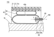
連通路63は、図5Aに示すように、第1拡張部材41の外部に位置する連通路63a(以下、単に「拡張部材40の外部の連通路63a」と称する)と、第1拡張部材41の内側に位置する連通路63b(以下、単に「拡張部材40の内空の連通路63b」と称する)と、を備えている。拡張部材40の外部の連通路63aの長さL1は、拡張部材40の内空の連通路63bの長さL2よりも短い。そのため、フィルム状弁部材60の拡張部材40から露出している部分の長手方向Yに沿う長さは、比較的短い。そのため、図5Cに示すように、フィルム状弁部材60は、周辺で行われる医療行為を阻害せず、また、患者の手首Wに接触し難く、患者の不快感を低減できる。 As shown in FIG. 5A, the communication passage 63 includes a communication passage 63a located outside the first expansion member 41 (hereinafter, simply referred to as “a communication passage 63a outside the expansion member 40”) and the first expansion member 41. It is provided with a communication passage 63b (hereinafter, simply referred to as "the communication passage 63b in the air of the expansion member 40") located inside the above. The length L1 of the communication passage 63a outside the expansion member 40 is shorter than the length L2 of the communication passage 63b in the air inside the expansion member 40. Therefore, the length of the portion of the film-shaped valve member 60 exposed from the expansion member 40 along the longitudinal direction Y is relatively short. Therefore, as shown in FIG. 5C, the film-shaped valve member 60 does not interfere with the medical practice performed in the surrounding area, and it is difficult for the patient to come into contact with the wrist W, so that the patient's discomfort can be reduced.

フィルム状弁部材60は、本実施形態では、図3に示すように、長手方向Yに伸びている2つの縁部のうち、先端側Y1の領域に、2枚のフィルム部材61、62を接合した接合部60c、60dを備え、基端側Y2の領域に、2枚のフィルム部材61、62が接合されていない非接合部60e、60fを備えている。そのため、2枚のフィルム部材61、62の基端側Y2の部分を、互いに離反する方向に変形させ、基端側Y2の開口部60bを開くことができる。そのため、注入部材70は、フィルム状弁部材60の基端側Y2の開口部60bから、容易に挿入される。なお、フィルム状弁部材60は、非接合部60e、60fを備えず、長手方向Yに伸びている縁部が全長に渡って接合されていてもよい。2枚のフィルム部材61、62の長手方向Yの縁部が全長に渡って接合されている場合、フィルム状弁部材60は、基端側Y2の開口部60bが突出部41bの基端側Y2の縁部と重なるように、その全てが、第1拡張部材41内に配置されていてもよい。すなわち、拡張部材40の外部の連通路63aの長さL1は、0であってもよい。 In the present embodiment, as shown in FIG. 3, the film-shaped valve member 60 has two film members 61 and 62 joined to the region of the tip end side Y1 of the two edges extending in the longitudinal direction Y. The bonded portions 60c and 60d are provided, and the non-bonded portions 60e and 60f to which the two film members 61 and 62 are not bonded are provided in the region of the proximal end side Y2. Therefore, the portions of the two film members 61 and 62 on the proximal end side Y2 can be deformed in a direction away from each other to open the opening 60b on the proximal end side Y2. Therefore, the injection member 70 is easily inserted from the opening 60b of the base end side Y2 of the film-shaped valve member 60. The film-shaped valve member 60 may not be provided with the non-joined portions 60e and 60f, and the edge portions extending in the longitudinal direction Y may be joined over the entire length. When the edges of the two film members 61 and 62 in the longitudinal direction Y are joined over the entire length, in the film-shaped valve member 60, the opening 60b of the proximal end side Y2 is the proximal end side Y2 of the protruding portion 41b. All of them may be arranged in the first expansion member 41 so as to overlap with the edge portion of the first expansion member 41. That is, the length L1 of the external passage 63a of the expansion member 40 may be 0.

フィルム部材61、62としては、特に限定されないが、例えば、塩化ビニル、ポリエチレン、ポリスチレン、エチレン-酢酸ビニル共重合体等の可撓性のプラスチックシートを用いることができる。 The film members 61 and 62 are not particularly limited, and for example, flexible plastic sheets such as vinyl chloride, polyethylene, polystyrene, and ethylene-vinyl acetate copolymer can be used.

(注入部材)
注入部材70は、図1に示すように、フィルム状弁部材60の連通路63に配置されるチューブ71と、チューブ71の基端側Y2の部分に取り付けられるとともに、シリンジS(「流体供給源」に相当)を連結可能な中空のコネクタ72と、を備えている。以下、注入部材70について説明する。なお、注入部材70は、注入部材70が止血器具10から抜去された状態で、コネクタ72側を「基端側」と称し、その反対側(チューブ71の端部のうち、チューブ71のコネクタに取り付けられていない側)を「先端側」と称する。
(Injection member)
As shown in FIG. 1, the injection member 70 is attached to the tube 71 arranged in the communication passage 63 of the film-shaped valve member 60 and the portion of the proximal end side Y2 of the tube 71, and is attached to the syringe S (“fluid supply source”). It is provided with a hollow connector 72 to which (corresponding to) can be connected. Hereinafter, the injection member 70 will be described. In the injection member 70, with the injection member 70 removed from the hemostatic device 10, the connector 72 side is referred to as the "base end side", and the opposite side (of the end portions of the tube 71, the connector of the tube 71). The side that is not attached) is referred to as the "tip side".

まず、チューブ71について説明する。 First, the tube 71 will be described.

チューブ71は、図3に示すように、略一定の外径を備える円筒状の本体部71aと、本体部71aの先端に連なるとともに、先端側Y1に向かって先細る筒状のテーパ部71bを備えている。このように、チューブ71は、テーパ部71bを備えているため、フィルム状弁部材60に容易に挿入できる。なお、チューブ71は、テーパ部71bを備えず、その全長に渡って略一定の外径を備えていてもよい。 As shown in FIG. 3, the tube 71 has a cylindrical main body portion 71a having a substantially constant outer diameter, and a tubular tapered portion 71b that is connected to the tip of the main body portion 71a and that tapers toward the tip end side Y1. I have. As described above, since the tube 71 is provided with the tapered portion 71b, it can be easily inserted into the film-shaped valve member 60. The tube 71 may not have the tapered portion 71b and may have a substantially constant outer diameter over the entire length thereof.

本体部71aの外径R1は、連通路63に配置可能な長さである限り特に限定されない。ただし、チューブ71とフィルム状弁部材60との間の隙間から、拡張部材40内の気体が外部に漏れるのを抑制する観点から、本体部71aの外径R1は、図7に示すように、フィルム状弁部材60の連通路63を形成している部分を略円形に変形させた場合の、フィルム状弁部材60の内表面の放射方向の長さR2と略同一の長さであることあることが好ましい。 The outer diameter R1 of the main body portion 71a is not particularly limited as long as it has a length that can be arranged in the continuous passage 63. However, from the viewpoint of suppressing the gas in the expansion member 40 from leaking to the outside from the gap between the tube 71 and the film-shaped valve member 60, the outer diameter R1 of the main body portion 71a is as shown in FIG. When the portion forming the communication passage 63 of the film-shaped valve member 60 is deformed into a substantially circular shape, the length may be substantially the same as the radial length R2 of the inner surface of the film-shaped valve member 60. Is preferable.

チューブ71は、図1に示すように、拡張部材40が未拡張の状態で、連通路63に配置されている。すなわち、止血器具10を術者に提供する段階で、チューブ71は、連通路63に配置されている。そのため、術者は、止血器具10の使用を開始する際に、連通路63にチューブ71を配置する(フィルム状弁部材60にチューブ71を挿入する)作業を行う必要がない。そのため、止血器具10は、術者の作業負担を軽減することができる。 As shown in FIG. 1, the tube 71 is arranged in the communication passage 63 in a state where the expansion member 40 is not expanded. That is, at the stage of providing the hemostatic device 10 to the operator, the tube 71 is arranged in the communication passage 63. Therefore, the surgeon does not need to perform the work of arranging the tube 71 in the communication passage 63 (inserting the tube 71 into the film-shaped valve member 60) when starting to use the hemostatic device 10. Therefore, the hemostatic device 10 can reduce the work load of the operator.

チューブ71は、図5Aに示すように、その先端が、連通路63の先端(先端側Y1の開口部60a)よりも基端側Y2の位置に配置された状態で、固定部71cによって、フィルム状弁部材60に固定されている。これにより、図5Bに示すように、拡張部材40が拡張し、かつ、術者がシリンジSによる気体の注入を停止した時点で、フィルム状弁部材60の先端側Y1の部分は、拡張部材40の内圧Tによって、拡張部材40の内空の連通路63bを閉じる方向に変形する。そのため、術者は、拡張部材40に気体を注入する際、連通路63におけるチューブ71の先端の位置を調整する必要がない。また、チューブ71の先端がフィルム状弁部材60の先端よりも先端側Y1に突出して(チューブ71の先端が先端側Y1の開口部60aから突出して)フィルム状弁部材60とチューブ71との間の隙間から拡張部材40内の気体が外部に漏れるのを、防止できる。 As shown in FIG. 5A, the tube 71 is formed by the fixing portion 71c in a state where the tip thereof is arranged at the position of the proximal end side Y2 with respect to the distal end of the communication passage 63 (the opening 60a of the distal end side Y1). It is fixed to the valve member 60. As a result, as shown in FIG. 5B, when the expansion member 40 expands and the operator stops the injection of gas by the syringe S, the portion of the film-shaped valve member 60 on the distal end side Y1 becomes the expansion member 40. The internal pressure T of the expansion member 40 deforms the expansion member 40 in the direction of closing the communication passage 63b in the air. Therefore, the operator does not need to adjust the position of the tip of the tube 71 in the communication passage 63 when injecting gas into the expansion member 40. Further, the tip of the tube 71 protrudes toward the tip side Y1 from the tip of the film-shaped valve member 60 (the tip of the tube 71 protrudes from the opening 60a of the tip side Y1) between the film-shaped valve member 60 and the tube 71. It is possible to prevent the gas in the expansion member 40 from leaking to the outside through the gap between the two.

固定部71cは、術者が注入部材70を基端側Y2に引く動作に伴って、注入部材70とフィルム状弁部材の固定状態を解除する。固定部71cの構成は、特に限定されないが、例えば、チューブ71とフィルム状弁部材60を接着や融着等した接合部によって構成してもよいし、チューブ71およびフィルム状弁部材60に設けられた機械的な連結部によって構成してもよい。なお、チューブ71は、フィルム状弁部材60に固定されている必要はなく、術者が、止血器具10の使用を開始する際に、フィルム状弁部材60にチューブ71を挿入してもよい。また、チューブ71をフィルム状弁部材60に固定する場合、チューブ71の先端の位置は、特に限定されない。例えば、チューブ71の先端は、フィルム状弁部材60の先端よりも先端側Y1に配置されていてもよい。 The fixing portion 71c releases the fixed state of the injection member 70 and the film-shaped valve member as the operator pulls the injection member 70 toward the proximal end side Y2. The configuration of the fixing portion 71c is not particularly limited, but may be configured by, for example, a joint portion in which the tube 71 and the film-shaped valve member 60 are bonded or fused, or may be provided on the tube 71 and the film-shaped valve member 60. It may be configured by a mechanical connecting portion. The tube 71 does not have to be fixed to the film-shaped valve member 60, and the operator may insert the tube 71 into the film-shaped valve member 60 when the operator starts using the hemostatic device 10. Further, when the tube 71 is fixed to the film-shaped valve member 60, the position of the tip of the tube 71 is not particularly limited. For example, the tip of the tube 71 may be arranged on the tip side Y1 of the tip of the film-shaped valve member 60.

次に、コネクタ72について説明する。 Next, the connector 72 will be described.

コネクタ72は、図4に示すように、シリンジSの先端部に連結される。コネクタ72をシリンジSの先端部に連結する方法は特に限定されないが、コネクタ72の内径とシリンジSの先端部の外径を略同一の長さに設定し、コネクタ72をシリンジSの先端部に嵌合させる方法、コネクタ72の内周面に雌ネジを設け、シリンジSの先端部の外周面に雄ネジを設け、コネクタ72をシリンジSの先端部に螺合させる方法、等を用いることができる。なお、コネクタ72は、シリンジSの先端部に対して着脱自在であることが好ましい。また、止血器具10と組み合わせて使用する流体供給源は、シリンジSである必要はなく、例えば、カフであってもよい。 As shown in FIG. 4, the connector 72 is connected to the tip end portion of the syringe S. The method of connecting the connector 72 to the tip of the syringe S is not particularly limited, but the inner diameter of the connector 72 and the outer diameter of the tip of the syringe S are set to substantially the same length, and the connector 72 is attached to the tip of the syringe S. A method of fitting, a method of providing a female screw on the inner peripheral surface of the connector 72, a male screw on the outer peripheral surface of the tip of the syringe S, and a method of screwing the connector 72 to the tip of the syringe S can be used. can. The connector 72 is preferably detachable from the tip of the syringe S. Further, the fluid supply source used in combination with the hemostatic device 10 does not have to be a syringe S, and may be, for example, a cuff.

(使用方法)
次に、本実施形態に係る止血器具10の使用例について説明する。
(how to use)
Next, an example of using the hemostatic device 10 according to the present embodiment will be described.

止血器具10を手首Wに装着する前は、図2に示すように、拡張部材40は、拡張していない状態となっている。図1に示すように、この際、注入部材70は、連通路63に配置されている。そのため、術者は、止血器具10の使用を開始する際に、注入部材70をフィルム状弁部材60に挿入する作業を行う必要がない。そのため、止血器具10は、術者の作業負担を軽減できる。 Before the hemostatic device 10 is attached to the wrist W, the expansion member 40 is in a non-expanded state as shown in FIG. As shown in FIG. 1, at this time, the injection member 70 is arranged in the communication passage 63. Therefore, the surgeon does not need to insert the injection member 70 into the film-shaped valve member 60 when starting to use the hemostatic device 10. Therefore, the hemostatic device 10 can reduce the work load of the operator.

図4に示すように、右手の手首Wの橈骨動脈Rに穿刺を行う場合、穿刺部位Pは、親指側へ片寄った位置にある。通常、穿刺部位Pにはイントロデューサーシース(図示省略)が留置されている。このイントロデューサーシースが留置されたままの状態の手首Wに帯体21を巻き付け、拡張部材40に設けられたマーカー50が穿刺部位P上に重なるように拡張部材40および帯体21を位置合わせして、面ファスナーの雄側31および雌側32を接触させて接合し、帯体21を手首Wに装着する。 As shown in FIG. 4, when puncturing the radial artery R of the wrist W of the right hand, the puncture site P is located at a position offset to the thumb side. Normally, an introducer sheath (not shown) is indwelled at the puncture site P. The band 21 is wrapped around the wrist W in which the introducer sheath is indwelled, and the expansion member 40 and the band 21 are aligned so that the marker 50 provided on the expansion member 40 overlaps the puncture site P. Then, the male side 31 and the female side 32 of the hook-and-loop fastener are brought into contact with each other and joined, and the band 21 is attached to the wrist W.

この際、止血器具10は、注入部材70が、橈骨動脈Rの血流の下流側(掌側)に向くように、手首Wに対して装着される。これにより、手首Wよりも上流側での手技や、上流側に位置する器具(例えば、血圧計等)に干渉することなしに、注入部材70およびシリンジSの操作が可能となる。また、止血器具10を、注入部材70が下流側に向くように右手の手首Wに装着することで、第1拡張部材41は、手首Wの親指側へ片寄って位置する橈骨動脈Rに位置する。なお、動脈の場合、血管の上流側とは、血管の心臓に近づく方向をいう。また、血管の下流側とは、血管の心臓から遠ざかる方向をいう。なお、止血器具10は、左手の手首の橈骨動脈に穿刺を行う場合に使用してもよい。この場合、注入部材70は、橈骨動脈の血流の上流側に向くように、左手の手首に対して装着される。 At this time, the hemostatic device 10 is attached to the wrist W so that the injection member 70 faces the downstream side (palm side) of the blood flow of the radial artery R. This makes it possible to operate the injection member 70 and the syringe S without interfering with the procedure on the upstream side of the wrist W or the device located on the upstream side (for example, a sphygmomanometer or the like). Further, by attaching the hemostatic device 10 to the wrist W of the right hand so that the injection member 70 faces the downstream side, the first expansion member 41 is located in the radial artery R located offset to the thumb side of the wrist W. .. In the case of an artery, the upstream side of the blood vessel means the direction of the blood vessel approaching the heart. Further, the downstream side of the blood vessel means a direction away from the heart of the blood vessel. The hemostatic device 10 may be used when puncturing the radial artery of the wrist of the left hand. In this case, the injection member 70 is attached to the wrist of the left hand so as to face the upstream side of the blood flow in the radial artery.

次に、術者は、注入部材70のコネクタ72にシリンジSを連結する。なお、術者は、シリンジSは、止血器具10を手首Wに装着する前に、注入部材70のコネクタ72に連結してもよい。 Next, the operator connects the syringe S to the connector 72 of the injection member 70. The surgeon may connect the syringe S to the connector 72 of the injection member 70 before attaching the hemostatic device 10 to the wrist W.

次に、術者は、図5Aに示すように、シリンジSの押し子を押して、気体を拡張部材40内に注入し、拡張部材40を拡張させる。術者は、拡張部材40を、穿刺部位Pからの出血を防止可能な程度に拡張させた後、穿刺部位Pからイントロデューサーシースを抜去する。 Next, as shown in FIG. 5A, the operator pushes the pusher of the syringe S to inject gas into the expansion member 40 and expand the expansion member 40. The operator expands the expansion member 40 to the extent that bleeding from the puncture site P can be prevented, and then removes the introducer sheath from the puncture site P.

次に、術者は、シリンジSの押し子を押して、さらに拡張部材40に気体を注入し、穿刺部位Pを圧迫止血可能な程度に、拡張部材40を拡張する。その結果、図5Bに示すように、フィルム状弁部材60は、拡張部材40の内圧Tによって、拡張部材40の内空の連通路63bを閉じる方向に変形する(本実施形態では、2枚のフィルム部材61、62の先端側Y1の部分が密着する)。なお、術者は、気体の注入量を調整することによって、症例に応じて、拡張部材40の拡張度合、すなわち、穿刺部位Pに作用する圧迫力F1の大きさを容易に調整することができる。例えば、術者は、仮に拡張部材40に気体を注入しすぎて拡張部材40が過拡張した場合は、シリンジSを用いて拡張部材40内から余剰な気体を排出すればよい。 Next, the operator pushes the pusher of the syringe S, further injects gas into the expansion member 40, and expands the expansion member 40 to the extent that the puncture site P can be compressed to stop bleeding. As a result, as shown in FIG. 5B, the film-shaped valve member 60 is deformed in the direction of closing the air passage 63b in the expansion member 40 due to the internal pressure T of the expansion member 40 (in the present embodiment, two sheets). The portion of the film members 61, 62 on the tip side Y1 is in close contact with each other). By adjusting the gas injection amount, the surgeon can easily adjust the degree of expansion of the expansion member 40, that is, the magnitude of the compression force F1 acting on the puncture site P, depending on the case. .. For example, if the operator injects too much gas into the expansion member 40 and the expansion member 40 is over-expanded, the operator may use the syringe S to discharge the excess gas from the inside of the expansion member 40.

次に、術者は、図5Cに示すように、注入部材70をフィルム状弁部材60から抜去する。フィルム状弁部材60は、拡張部材40の内空の連通路63bを閉じる方向に変形しているため、拡張部材40の拡張状態を維持できる。このように、注入部材70は、フィルム状弁部材60から抜去されるため、注入部材70は、周辺で行われる医療行為を阻害せず、また、患者の手首Wに触れないため、患者の不快感を軽減できる。また、フィルム状弁部材60は、拡張部材40の外部の連通路63aが、拡張部材40の内空の連通路63bよりも短く構成されている。そのため、フィルム状弁部材60は、周辺で行われる医療行為を阻害せず、また、患者の手首Wに触れ難く、患者の不快感を低減できる。また、術者は注入部材70を抜去するだけでよいため、術者の作業負担は増加しない。 Next, the operator removes the injection member 70 from the film-shaped valve member 60 as shown in FIG. 5C. Since the film-shaped valve member 60 is deformed in the direction of closing the communication passage 63b in the inner space of the expansion member 40, the expanded state of the expansion member 40 can be maintained. In this way, since the injection member 70 is removed from the film-shaped valve member 60, the injection member 70 does not interfere with the medical practice performed in the vicinity and does not touch the wrist W of the patient, so that the patient is not able to do so. Pleasure can be reduced. Further, in the film-shaped valve member 60, the communication passage 63a outside the expansion member 40 is shorter than the communication passage 63b in the inner space of the expansion member 40. Therefore, the film-shaped valve member 60 does not interfere with the medical practice performed in the surrounding area, and it is difficult for the patient's wrist W to be touched, so that the patient's discomfort can be reduced. Further, since the operator only has to remove the injection member 70, the work load of the operator does not increase.

次に、術者は、段階的に、シリンジSが連結された注入部材70をフィルム状弁部材60に挿入し、拡張部材40内の気体を外部に排出する(減圧作業)。これによって、例えば、拡張した拡張部材40が、長時間にわたって穿刺部位Pおよびその周辺の血管や神経を圧迫し続けて、患者がしびれや痛みを感じたり、血管が閉塞したりするのを防止できる。 Next, the operator stepwise inserts the injection member 70 to which the syringe S is connected into the film-shaped valve member 60, and discharges the gas in the expansion member 40 to the outside (decompression work). Thereby, for example, the dilated expansion member 40 can continue to press the blood vessels and nerves in and around the puncture site P for a long period of time to prevent the patient from feeling numbness, pain, or obstruction of the blood vessels. ..

なお、仮に、止血が十分に行われていない場合、術者は、シリンジSが連結された注入部材70をフィルム状弁部材60に挿入し、拡張部材40に気体を注入して、拡張部材40の内圧を上昇させてもよい。 If hemostasis is not sufficiently performed, the surgeon inserts the injection member 70 to which the syringe S is connected into the film-shaped valve member 60, injects gas into the expansion member 40, and injects gas into the expansion member 40. The internal pressure of the syringe may be increased.

所定の時間が経過して、穿刺部位Pの止血が完了したら、術者は、止血器具10を患者の手首Wから取り外す。止血器具10は、面ファスナーの雄側31および雌側32を剥がすことによって手首Wから取り外される。 After the predetermined time has elapsed and the hemostatic of the puncture site P is completed, the operator removes the hemostatic device 10 from the patient's wrist W. The hemostatic device 10 is removed from the wrist W by peeling off the male side 31 and the female side 32 of the hook-and-loop fastener.

以上のように、止血器具10は、手首Wの穿刺部位Pに巻きつけるための帯体21と、帯体21を手首Wに巻きつけた状態で固定する固定部材30と、帯体21が手首Wに巻き付けられた状態で、帯体21の内周面側に配置される拡張部材40と、拡張部材40に配置され、拡張部材40の内空41a、42aと外部とを連通する連通路63を備えたフィルム状弁部材60と、連通路63を介して拡張部材40の内空41a、42aに気体を導入可能な注入部材70と、を備えている。拡張部材40の外部の連通路63aは、拡張部材40の内空の連通路63bよりも短く形成されている。拡張部材40が拡張され、かつ、注入部材70がフィルム状弁部材60から抜去された状態で、フィルム状弁部材60は、拡張部材40の内圧Tにより、拡張部材40の内空の連通路63bを閉じる方向に変形する。 As described above, the hemostatic device 10 includes a band 21 for wrapping the band 21 around the puncture site P of the wrist W, a fixing member 30 for fixing the band 21 in a state of being wrapped around the wrist W, and the band 21 for the wrist. An expansion member 40 arranged on the inner peripheral surface side of the band 21 in a state of being wound around W, and a communication passage 63 arranged on the expansion member 40 and communicating the inner spaces 41a and 42a of the expansion member 40 with the outside. A film-shaped valve member 60 is provided, and an injection member 70 capable of introducing gas into the inner spaces 41a and 42a of the expansion member 40 via the communication passage 63. The communication passage 63a outside the expansion member 40 is formed shorter than the communication passage 63b in the air inside the expansion member 40. With the expansion member 40 expanded and the injection member 70 removed from the film-shaped valve member 60, the film-shaped valve member 60 has a continuous passage 63b in the air of the expansion member 40 due to the internal pressure T of the expansion member 40. Transforms in the closing direction.

上記のように構成した止血器具10によれば、フィルム状弁部材60は、拡張部材40が拡張され、かつ、注入部材70がフィルム状弁部材60から抜去された状態で、拡張部材40の内圧Tによって、拡張部材40の内空の連通路63bを閉じる方向に変形する。そのため、注入部材70がフィルム状弁部材60から抜去された状態で、フィルム状弁部材60は、拡張部材40内の気体が外部へ漏れるのを抑制し、拡張部材40は、拡張状態を維持できる。このように、注入部材70は、フィルム状弁部材60から抜去されるため、周辺で行われる医療行為を阻害せず、また、患者の肢体に触れないため、患者の不快感を低減できる。また、フィルム状弁部材60は、拡張部材40の外部の連通路63aが、拡張部材40の内空の連通路63bよりも短くなるように構成されている。そのため、フィルム状弁部材60は、拡張部材40の外部に露出している部分が比較的短い。そのため、フィルム状弁部材60は、周辺で行われる医療行為を阻害せず、また、患者の肢体に触れ難く、患者の不快感を低減できる。このように、止血器具10は、術者が注入部材70をフィルム状弁部材60から抜去するという簡便な作業により、術者の作業負担を増加させることなく、周辺で行われる医療行為の邪魔にならならず、かつ、患者の不快感を低減することができる。 According to the hemostatic device 10 configured as described above, the film-shaped valve member 60 has the internal pressure of the expansion member 40 in a state where the expansion member 40 is expanded and the injection member 70 is removed from the film-shaped valve member 60. By T, the expansion member 40 is deformed in the direction of closing the communication passage 63b in the inner sky. Therefore, in a state where the injection member 70 is removed from the film-shaped valve member 60, the film-shaped valve member 60 suppresses the gas in the expansion member 40 from leaking to the outside, and the expansion member 40 can maintain the expanded state. .. As described above, since the injection member 70 is removed from the film-shaped valve member 60, it does not interfere with the medical practice performed in the vicinity and does not touch the limbs of the patient, so that the discomfort of the patient can be reduced. Further, the film-shaped valve member 60 is configured such that the communication passage 63a outside the expansion member 40 is shorter than the communication passage 63b in the inner space of the expansion member 40. Therefore, the film-shaped valve member 60 has a relatively short portion exposed to the outside of the expansion member 40. Therefore, the film-shaped valve member 60 does not interfere with the medical practice performed in the surrounding area, is difficult to touch the limbs of the patient, and can reduce the discomfort of the patient. As described above, the hemostatic device 10 interferes with the medical practice performed in the surrounding area without increasing the work load of the operator by the simple operation that the operator removes the injection member 70 from the film-shaped valve member 60. In addition, the discomfort of the patient can be reduced.

また、注入部材70は、拡張部材40が未拡張の状態で、連通路63に配置されている。すなわち、止血器具10を術者に提供する段階で、注入部材70は、連通路63に配置されている。そのため、術者は、止血器具10の使用開始時に、連通路63に注入部材70を配置する作業を行う必要がない。そのため、止血器具10は、術者の作業負担を軽減できる。 Further, the injection member 70 is arranged in the communication passage 63 in a state where the expansion member 40 is not expanded. That is, at the stage of providing the hemostatic device 10 to the operator, the injection member 70 is arranged in the communication passage 63. Therefore, the surgeon does not need to perform the work of arranging the injection member 70 in the communication passage 63 at the start of using the hemostatic device 10. Therefore, the hemostatic device 10 can reduce the work load of the operator.

また、注入部材70の先端が、連通路63の先端よりも基端側Y2の位置に配置された状態で、注入部材70は、フィルム状弁部材60に固定されている。そのため、拡張部材40の拡張が完了し、術者が、シリンジSによる気体の注入を停止した時点で、拡張部材40の内圧Tによって、フィルム状弁部材60の先端側Y1の部分は、拡張部材40の内空の連通路63bを閉じる方向に変形する。そのため、術者が拡張部材40に気体を注入する際、注入部材70の先端が、フィルム状弁部材60の先端よりも先端側に突出し、フィルム状弁部材60と注入部材70の間の隙間から拡張部材40内の気体が外部に漏れるのを、防止できる。 Further, the injection member 70 is fixed to the film-shaped valve member 60 in a state where the tip of the injection member 70 is arranged at the position of the proximal end side Y2 with respect to the tip of the communication passage 63. Therefore, when the expansion of the expansion member 40 is completed and the operator stops the injection of gas by the syringe S, the internal pressure T of the expansion member 40 causes the portion of the film-shaped valve member 60 on the distal end side Y1 to be the expansion member. It is deformed in the direction of closing the communication passage 63b in the inner sky of 40. Therefore, when the operator injects gas into the expansion member 40, the tip of the injection member 70 protrudes toward the tip side of the tip of the film-shaped valve member 60, and the tip of the injection member 70 protrudes from the gap between the film-shaped valve member 60 and the injection member 70. It is possible to prevent the gas in the expansion member 40 from leaking to the outside.

また、注入部材70は、その基端側Y2の部分に、注入部材70に気体を供給するシリンジSを連結可能なコネクタ72を備える。そのため、注入部材70は、シリンジSに容易に連結できる。 Further, the injection member 70 includes a connector 72 to which a syringe S for supplying gas to the injection member 70 can be connected to a portion of Y2 on the proximal end side thereof. Therefore, the injection member 70 can be easily connected to the syringe S.

また、注入部材70は、その先端側Y1の部分に、注入部材70の先端側に向かって先細るテーパ部71bを備える。そのため、注入部材70は、連通路63に容易に配置することができる。 Further, the injection member 70 is provided with a tapered portion 71b that tapers toward the tip end side of the injection member 70 in the portion of the tip end side Y1. Therefore, the injection member 70 can be easily arranged in the communication passage 63.

(変形例1)
図8Aおよび図8Bは、変形例1に係る止血器具110を示す図である。以下、前述した実施形態と同様の構成には同一の符号を付し、その説明を省略する。
(Modification 1)
8A and 8B are views showing the hemostatic device 110 according to the first modification. Hereinafter, the same reference numerals will be given to the same configurations as those of the above-described embodiments, and the description thereof will be omitted.

変形例1に係る止血器具110は、拡張部材40の内圧Tにより、フィルム状弁部材60が拡張部材40の内空の連通路63bを閉じる方向に変形した際に、拡張部材40の内空と外部とを連通して、拡張部材40内の気体を外部に徐々に排出する減圧機構180を備える点において、上記実施形態に係る止血器具と相違する。 The hemostatic device 110 according to the first modification is formed with the inner space of the expansion member 40 when the film-shaped valve member 60 is deformed in the direction of closing the communication passage 63b in the inner space of the expansion member 40 due to the internal pressure T of the expansion member 40. It differs from the hemostatic device according to the above embodiment in that it is provided with a decompression mechanism 180 that communicates with the outside and gradually discharges the gas in the expansion member 40 to the outside.

減圧機構180は、連通路63の先端から基端に向かって伸びている連続気泡型の発泡体によって構成している。そのため、フィルム状弁部材60が拡張部材40の内空の連通路63bを閉じる方向に変形した際、減圧機構180の連続気泡(空隙)を介して、拡張部材40内の気体が、外部に徐々に排出される(図中、破線の矢印で気体の流れを示す)。これにより、術者が、減圧作業を行わなくても、自動的に拡張部材40内の気体が外部に排出されるため、止血器具110は、術者の作業負担をより一層軽減できる。 The decompression mechanism 180 is composed of an open cell type foam extending from the tip end of the communication passage 63 toward the base end. Therefore, when the film-shaped valve member 60 is deformed in the direction of closing the communication passage 63b in the inner space of the expansion member 40, the gas in the expansion member 40 gradually moves to the outside through the open cells (voids) of the decompression mechanism 180. (In the figure, the dashed arrow indicates the gas flow). As a result, the gas in the expansion member 40 is automatically discharged to the outside even if the operator does not perform the decompression operation, so that the hemostatic device 110 can further reduce the work load of the operator.

減圧機構180は、フィルム状弁部材60を構成する2枚のフィルム部材61、62の一方に接合されている。 The pressure reducing mechanism 180 is joined to one of the two film members 61 and 62 constituting the film-shaped valve member 60.

減圧機構180の構成材料は、連続気泡型の発泡体である限り特に限定されないが、例えば、連続気泡型のポリウレタンフォーム、ポリスチレンフォーム、ポリオレフィンフォーム等を用いることができる。 The constituent material of the depressurizing mechanism 180 is not particularly limited as long as it is an open cell type foam, and for example, open cell type polyurethane foam, polystyrene foam, polyolefin foam and the like can be used.

このように、上記変形例1に係る止血器具110は、フィルム状弁部材60が拡張部材40の内圧Tにより、拡張部材40の内空に位置する連通路63bを閉じる方向に変形した際に、拡張部材40の内空と外部とを連通して、拡張部材40内の気体を徐々に外部に排出する減圧機構180をさらに備える。これにより、術者が、減圧作業を行わなくても、自動的に拡張部材40内の気体が外部に排出されるため、止血器具110は、術者の作業負担をより一層軽減できる。 As described above, the hemostatic device 110 according to the first modification is deformed in the direction of closing the communication passage 63b located in the inner space of the expansion member 40 due to the internal pressure T of the expansion member 40. Further, a decompression mechanism 180 is further provided, in which the inside air of the expansion member 40 and the outside are communicated with each other and the gas in the expansion member 40 is gradually discharged to the outside. As a result, the gas in the expansion member 40 is automatically discharged to the outside even if the operator does not perform the decompression operation, so that the hemostatic device 110 can further reduce the work load of the operator.

また、減圧機構180は、連通路63に配置される連続気泡型の発泡部材を備える。そのため、発泡部材の連続気泡を介して、拡張部材40内の気体を外部に徐々に排出できる。 Further, the decompression mechanism 180 includes an open cell type foaming member arranged in the communication passage 63. Therefore, the gas in the expansion member 40 can be gradually discharged to the outside through the open cells of the foaming member.

(変形例2)
図9Aおよび図9Bは、変形例2に係る止血器具210を示す図である。以下、前述した実施形態と同様の構成には同一の符号を付し、その説明を省略する。
(Modification 2)
9A and 9B are views showing the hemostatic device 210 according to the second modification. Hereinafter, the same reference numerals will be given to the same configurations as those of the above-described embodiments, and the description thereof will be omitted.

変形例2に係る止血器具210は、減圧機構280の構成において、変形例1の止血器具110の減圧機構180と相違する。 The hemostatic device 210 according to the second modification is different from the decompression mechanism 180 of the hemostatic device 110 of the first modification in the configuration of the decompression mechanism 280.

減圧機構280は、フィルム状弁部材60を構成する2枚のフィルム部材61、62のそれぞれの内面に設けた溝部281、282によって構成している。溝部281、282は、フィルム部材61、62の先端から基端に向かって伸びている。なお、減圧機構280は、少なくとも1つの溝部を備えていればよく、例えば、溝部は、1つであってもよいし、3つ以上であってもよい。 The decompression mechanism 280 is composed of groove portions 281 and 282 provided on the inner surfaces of the two film members 61 and 62 constituting the film-shaped valve member 60, respectively. The groove portions 281 and 282 extend from the tip ends of the film members 61 and 62 toward the base end. The decompression mechanism 280 may include at least one groove, and may have, for example, one groove or three or more grooves.

術者は、図9Bに示すように、拡張部材40を拡張させた後、注入部材70をフィルム状弁部材60から抜去する。これによって、フィルム状弁部材60は、拡張部材40の内圧Tによって、連通路63を閉じる方向に変形する。拡張部材40内の気体は、溝部281、282を介して、拡張部材40の外部に徐々に排出される。術者が、減圧作業を行わなくても、自動的に拡張部材40内の気体が外部に排出されるため、止血器具210は、術者の作業負担をより一層軽減できる。 As shown in FIG. 9B, the operator expands the expansion member 40 and then removes the injection member 70 from the film-shaped valve member 60. As a result, the film-shaped valve member 60 is deformed in the direction of closing the communication passage 63 due to the internal pressure T of the expansion member 40. The gas in the expansion member 40 is gradually discharged to the outside of the expansion member 40 through the grooves 281 and 282. Since the gas in the expansion member 40 is automatically discharged to the outside even if the operator does not perform the decompression operation, the hemostatic device 210 can further reduce the work load of the operator.

このように、上記変形例2に係る止血器具210では、減圧機構280は、フィルム状弁部材60の内面において、連通路63に沿って形成された溝部281、282を備える。そのため、溝部281、282を介して、拡張部材40内の気体を徐々に排出できる。 As described above, in the hemostatic device 210 according to the second modification, the pressure reducing mechanism 280 includes grooves 281 and 282 formed along the communication passage 63 on the inner surface of the film-shaped valve member 60. Therefore, the gas in the expansion member 40 can be gradually discharged through the grooves 281 and 282.

以上、実施形態および変形例を通じて本発明に係る止血器具を説明したが、本発明は説明した各構成のみに限定されるものでなく、特許請求の範囲の記載に基づいて適宜変更することが可能である。 Although the hemostatic device according to the present invention has been described above through embodiments and modifications, the present invention is not limited to each of the described configurations and can be appropriately modified based on the description of the scope of claims. Is.

例えば、止血器具を構成する各部は、同様の機能を発揮し得る任意の構成のものと置換することができる。また、任意の構成物が付加されていてもよい。 For example, each part constituting the hemostatic device can be replaced with an arbitrary configuration capable of exerting a similar function. Further, any component may be added.

また、本発明は、手首に装着して使用する止血器具に限らず、脚等に装着して使用する止血器具にも適用することができる。 Further, the present invention can be applied not only to a hemostatic device worn on a wrist and used, but also to a hemostatic device worn on a leg or the like.

また、フィルム状弁部材は、第1拡張部材ではなく、第2拡張部材に配置されていてもよい。 Further, the film-shaped valve member may be arranged on the second expansion member instead of the first expansion member.

また、拡張部材は、第2拡張部材を備えなくてもよい。また、拡張部材は、第2拡張部材の代わりに、拡張せずに第1拡張部材を押圧する押圧部材を備えていてもよい。 Further, the expansion member does not have to include the second expansion member. Further, the expansion member may include a pressing member that presses the first expansion member without expanding, instead of the second expansion member.

10、110、210 止血器具、
21 帯体、
30 固定部材、
40 拡張部材、
60 フィルム状弁部材、
63 連通路、
63a 拡張部材の外部の連通路、
63b 拡張部材の内空の連通路、
70 注入部材、
71b テーパ部、
71c 固定部、
72 コネクタ、
180、280 減圧機構、
281、282 溝部、
P 穿刺部位(止血すべき部位)、
T 拡張部材の内圧、
W 手首(肢体)。
10, 110, 210 Hemostasis device,
21 obi,
30 Fixing member,
40 expansion member,
60 film-shaped valve member,
63 consecutive passages,
63a External passageway of the expansion member,
63b An air passage in the expansion member,
70 injection member,
71b taper part,
71c fixed part,
72 connectors,
180, 280 decompression mechanism,
281, 282 groove,
P Puncture site (site to stop bleeding),
Internal pressure of T expansion member,
W Wrist (limb).

Claims (6)

肢体の止血すべき部位に巻きつけるための帯体と、
前記帯体を前記肢体に巻きつけた状態で固定する固定部材と、
前記帯体が前記肢体に巻き付けられた状態で、前記帯体の内周面側に配置される拡張部材と、
前記拡張部材に配置され、前記拡張部材の内空と外部とを連通する連通路を備えたフィルム状弁部材と、
前記連通路を介して前記拡張部材の前記内空に流体を導入可能な注入部材と、
前記注入部材の先端が前記連通路の先端よりも基端側の位置に配置された状態で、前記注入部材を前記フィルム状弁部材に固定する固定部と、を備え、
前記拡張部材は、平面視において、周縁部の一部が外方に向かって突出した突出部を有する2枚のシート材を重ねて、前記2枚のシート材の周縁部同士を接合した袋体で構成され、
前記拡張部材の前記外部の前記連通路は、前記拡張部材の前記内空の前記連通路よりも短く形成されており、
前記拡張部材が拡張され、かつ、前記注入部材が前記フィルム状弁部材から抜去された状態で、前記フィルム状弁部材は、前記拡張部材の内圧により、前記拡張部材の前記内空に位置する前記連通路を閉じる方向に変形可能に構成され、
前記注入部材は、前記拡張部材が未拡張の状態では、前記連通路に配置され、
前記固定部は、前記フィルム状弁部材の外部側に位置し、前記注入部材と前記フィルム状弁部材とを接合する接合部であり、使用者が前記注入部材を引く動作に伴って前記注入部材と前記フィルム状弁部材の固定状態を解除可能に構成され、
前記突出部は、前記フィルム状弁部材の外表面に気密に接合される、止血器具。
A band to wrap around the limb where hemostasis should be,
A fixing member that fixes the band in a state of being wrapped around the limb, and
With the band wrapped around the limb, an expansion member arranged on the inner peripheral surface side of the band, and
A film-shaped valve member arranged in the expansion member and provided with a communication passage that communicates the inside air and the outside of the expansion member.
An injection member capable of introducing a fluid into the inner space of the expansion member via the communication passage, and an injection member.
A fixing portion for fixing the injection member to the film-shaped valve member in a state where the tip of the injection member is arranged at a position closer to the proximal end side than the tip of the communication passage is provided.
In a plan view, the expansion member is a bag body in which two sheet materials having a protruding portion in which a part of the peripheral edge portion protrudes outward are stacked and the peripheral edges of the two sheet materials are joined to each other. Consists of
The outer passageway of the expansion member is formed shorter than the inner passageway of the expansion member.
With the expansion member expanded and the injection member removed from the film-shaped valve member, the film-shaped valve member is located in the inner space of the expansion member due to the internal pressure of the expansion member. It is configured to be deformable in the direction of closing the passage,
The injection member is arranged in the communication passage when the expansion member is not expanded.
The fixing portion is a joint portion located on the outer side of the film-shaped valve member and joins the injection member and the film-shaped valve member, and the injection member is accompanied by an operation of the user pulling the injection member. And the film-shaped valve member can be released from the fixed state.
The protruding portion is a hemostatic device that is airtightly bonded to the outer surface of the film-shaped valve member .
前記注入部材は、その基端側の部分に、前記注入部材に流体を供給する流体供給源を連結可能なコネクタを備える、請求項に記載の止血器具。 The hemostatic device according to claim 1 , wherein the injection member includes a connector at a portion on the proximal end side thereof to which a fluid supply source for supplying a fluid to the injection member can be connected. 前記注入部材は、その先端側の部分に、前記注入部材の先端側に向かって先細るテーパ部を備える、請求項1または2に記載の止血器具。 The hemostatic device according to claim 1 or 2 , wherein the injection member is provided with a tapered portion that tapers toward the tip end side of the injection member. 前記フィルム状弁部材が、前記拡張部材の内圧により、前記拡張部材の前記内空に位置する前記連通路を閉じる方向に変形した際に、前記拡張部材の前記内空と前記外部とを連通して、前記拡張部材内の前記流体を徐々に前記外部に排出する減圧機構をさらに備える、請求項1~のいずれか1項に記載の止血器具。 When the film-shaped valve member is deformed in the direction of closing the communication passage located in the inner space of the expansion member due to the internal pressure of the expansion member, the inner space of the expansion member and the outside of the expansion member are communicated with each other. The hemostatic device according to any one of claims 1 to 3 , further comprising a decompression mechanism for gradually discharging the fluid in the expansion member to the outside. 前記減圧機構は、前記連通路に配置される連続気泡型の発泡体を備える、請求項に記載の止血器具。 The hemostatic device according to claim 4 , wherein the decompression mechanism includes an open-cell foam type foam arranged in the communication passage. 前記減圧機構は、前記フィルム状弁部材の内面において、前記連通路に沿って形成された溝部を備える、請求項に記載の止血器具。 The hemostatic device according to claim 4 , wherein the decompression mechanism includes a groove formed along the communication passage on the inner surface of the film-shaped valve member.
JP2017186775A 2017-09-27 2017-09-27 Hemostasis device Active JP7018281B2 (en)

Priority Applications (1)

Application Number Priority Date Filing Date Title
JP2017186775A JP7018281B2 (en) 2017-09-27 2017-09-27 Hemostasis device

Applications Claiming Priority (1)

Application Number Priority Date Filing Date Title
JP2017186775A JP7018281B2 (en) 2017-09-27 2017-09-27 Hemostasis device

Publications (2)

Publication Number Publication Date
JP2019058498A JP2019058498A (en) 2019-04-18
JP7018281B2 true JP7018281B2 (en) 2022-02-10

Family

ID=66176931

Family Applications (1)

Application Number Title Priority Date Filing Date
JP2017186775A Active JP7018281B2 (en) 2017-09-27 2017-09-27 Hemostasis device

Country Status (1)

Country Link
JP (1) JP7018281B2 (en)

Families Citing this family (5)

* Cited by examiner, † Cited by third party
Publication number Priority date Publication date Assignee Title
JP7066642B2 (en) 2016-07-18 2022-05-13 メリット・メディカル・システムズ・インコーポレイテッド Inflatable radial artery compression device
JP7458319B2 (en) 2017-11-03 2024-03-29 メリット・メディカル・システムズ・インコーポレイテッド Hemostatic devices and methods of use
EP3773257A4 (en) 2018-04-11 2021-12-22 Merit Medical Systems, Inc. Inflatable compression device
USD911516S1 (en) 2018-06-19 2021-02-23 Merit Medical Systems, Inc. Hemostasis device
CN110236921B (en) * 2019-06-19 2021-07-30 浙江大学医学院附属妇产科医院 Helimrick first aid machine

Citations (5)

* Cited by examiner, † Cited by third party
Publication number Priority date Publication date Assignee Title
JP2000515773A (en) 1995-07-10 2000-11-28 ヴィーダケア インターナショナル インコーポレイテッド Wound closure hemostasis device
JP2004359320A (en) 2003-06-06 2004-12-24 Topack:Kk Tubular bag and method for using it
JP2005218461A (en) 2004-02-03 2005-08-18 Dairin Kk Set of air infusion pump and medical appliance with air inlet
JP2005318998A (en) 2004-05-07 2005-11-17 Terumo Corp Hemostatic device
JP2017000260A (en) 2015-06-05 2017-01-05 テルモ株式会社 Hemostatic device

Family Cites Families (2)

* Cited by examiner, † Cited by third party
Publication number Priority date Publication date Assignee Title
JPS5248293A (en) * 1975-10-16 1977-04-16 Nippon Medical Supply Hemostatc band
JPH07100142A (en) * 1993-10-04 1995-04-18 Sumitomo Rubber Ind Ltd Tourniquet and pump for charging and discharging fluid

Patent Citations (5)

* Cited by examiner, † Cited by third party
Publication number Priority date Publication date Assignee Title
JP2000515773A (en) 1995-07-10 2000-11-28 ヴィーダケア インターナショナル インコーポレイテッド Wound closure hemostasis device
JP2004359320A (en) 2003-06-06 2004-12-24 Topack:Kk Tubular bag and method for using it
JP2005218461A (en) 2004-02-03 2005-08-18 Dairin Kk Set of air infusion pump and medical appliance with air inlet
JP2005318998A (en) 2004-05-07 2005-11-17 Terumo Corp Hemostatic device
JP2017000260A (en) 2015-06-05 2017-01-05 テルモ株式会社 Hemostatic device

Also Published As

Publication number Publication date
JP2019058498A (en) 2019-04-18

Similar Documents

Publication Publication Date Title
JP7018281B2 (en) Hemostasis device
JP6936223B2 (en) Hemostatic device
JP6885941B2 (en) Hemostatic device
JP6893206B2 (en) Hemostatic device
JP6783083B2 (en) Hemostatic device
JP6740232B2 (en) Hemostatic device
JP7041056B2 (en) Hemostasis device
US20200367907A1 (en) Hemostatic device
JP6959219B2 (en) Hemostatic device
JP6725343B2 (en) Hemostatic device
JP6730137B2 (en) Hemostatic device
JP6859346B2 (en) Hemostatic device
JP6859345B2 (en) Hemostatic device
JP6573310B2 (en) Hemostatic device
JP6667392B2 (en) Hemostatic device
WO2020067164A1 (en) Hemostatic instrument
WO2019208714A1 (en) Hemostatic instrument

Legal Events

Date Code Title Description
A621 Written request for application examination

Free format text: JAPANESE INTERMEDIATE CODE: A621

Effective date: 20200610

A977 Report on retrieval

Free format text: JAPANESE INTERMEDIATE CODE: A971007

Effective date: 20210422

A131 Notification of reasons for refusal

Free format text: JAPANESE INTERMEDIATE CODE: A131

Effective date: 20210427

A601 Written request for extension of time

Free format text: JAPANESE INTERMEDIATE CODE: A601

Effective date: 20210622

A521 Request for written amendment filed

Free format text: JAPANESE INTERMEDIATE CODE: A523

Effective date: 20210820

TRDD Decision of grant or rejection written
A01 Written decision to grant a patent or to grant a registration (utility model)

Free format text: JAPANESE INTERMEDIATE CODE: A01

Effective date: 20220104

A61 First payment of annual fees (during grant procedure)

Free format text: JAPANESE INTERMEDIATE CODE: A61

Effective date: 20220131

R150 Certificate of patent or registration of utility model

Ref document number: 7018281

Country of ref document: JP

Free format text: JAPANESE INTERMEDIATE CODE: R150