EP3483906B1 - Spulenvorrichtung - Google Patents
Spulenvorrichtung Download PDFInfo
- Publication number
- EP3483906B1 EP3483906B1 EP17823938.0A EP17823938A EP3483906B1 EP 3483906 B1 EP3483906 B1 EP 3483906B1 EP 17823938 A EP17823938 A EP 17823938A EP 3483906 B1 EP3483906 B1 EP 3483906B1
- Authority
- EP
- European Patent Office
- Prior art keywords
- cover
- base
- fixing member
- coil device
- coil
- Prior art date
- Legal status (The legal status is an assumption and is not a legal conclusion. Google has not performed a legal analysis and makes no representation as to the accuracy of the status listed.)
- Active
Links
Images








Classifications
-
- H—ELECTRICITY
- H01—ELECTRIC ELEMENTS
- H01F—MAGNETS; INDUCTANCES; TRANSFORMERS; SELECTION OF MATERIALS FOR THEIR MAGNETIC PROPERTIES
- H01F27/00—Details of transformers or inductances, in general
- H01F27/02—Casings
-
- B—PERFORMING OPERATIONS; TRANSPORTING
- B60—VEHICLES IN GENERAL
- B60L—PROPULSION OF ELECTRICALLY-PROPELLED VEHICLES; SUPPLYING ELECTRIC POWER FOR AUXILIARY EQUIPMENT OF ELECTRICALLY-PROPELLED VEHICLES; ELECTRODYNAMIC BRAKE SYSTEMS FOR VEHICLES IN GENERAL; MAGNETIC SUSPENSION OR LEVITATION FOR VEHICLES; MONITORING OPERATING VARIABLES OF ELECTRICALLY-PROPELLED VEHICLES; ELECTRIC SAFETY DEVICES FOR ELECTRICALLY-PROPELLED VEHICLES
- B60L53/00—Methods of charging batteries, specially adapted for electric vehicles; Charging stations or on-board charging equipment therefor; Exchange of energy storage elements in electric vehicles
- B60L53/10—Methods of charging batteries, specially adapted for electric vehicles; Charging stations or on-board charging equipment therefor; Exchange of energy storage elements in electric vehicles characterised by the energy transfer between the charging station and the vehicle
- B60L53/12—Inductive energy transfer
-
- B—PERFORMING OPERATIONS; TRANSPORTING
- B60—VEHICLES IN GENERAL
- B60L—PROPULSION OF ELECTRICALLY-PROPELLED VEHICLES; SUPPLYING ELECTRIC POWER FOR AUXILIARY EQUIPMENT OF ELECTRICALLY-PROPELLED VEHICLES; ELECTRODYNAMIC BRAKE SYSTEMS FOR VEHICLES IN GENERAL; MAGNETIC SUSPENSION OR LEVITATION FOR VEHICLES; MONITORING OPERATING VARIABLES OF ELECTRICALLY-PROPELLED VEHICLES; ELECTRIC SAFETY DEVICES FOR ELECTRICALLY-PROPELLED VEHICLES
- B60L53/00—Methods of charging batteries, specially adapted for electric vehicles; Charging stations or on-board charging equipment therefor; Exchange of energy storage elements in electric vehicles
- B60L53/30—Constructional details of charging stations
-
- H—ELECTRICITY
- H01—ELECTRIC ELEMENTS
- H01F—MAGNETS; INDUCTANCES; TRANSFORMERS; SELECTION OF MATERIALS FOR THEIR MAGNETIC PROPERTIES
- H01F27/00—Details of transformers or inductances, in general
- H01F27/28—Coils; Windings; Conductive connections
-
- H—ELECTRICITY
- H01—ELECTRIC ELEMENTS
- H01F—MAGNETS; INDUCTANCES; TRANSFORMERS; SELECTION OF MATERIALS FOR THEIR MAGNETIC PROPERTIES
- H01F38/00—Adaptations of transformers or inductances for specific applications or functions
- H01F38/14—Inductive couplings
-
- H—ELECTRICITY
- H02—GENERATION; CONVERSION OR DISTRIBUTION OF ELECTRIC POWER
- H02J—ELECTRIC POWER NETWORKS; CIRCUIT ARRANGEMENTS OR SYSTEMS FOR SUPPLYING OR DISTRIBUTING ELECTRIC POWER; SYSTEMS FOR STORING ELECTRIC ENERGY
- H02J7/00—Circuit arrangements for charging or discharging batteries or for supplying loads from batteries
-
- H—ELECTRICITY
- H01—ELECTRIC ELEMENTS
- H01F—MAGNETS; INDUCTANCES; TRANSFORMERS; SELECTION OF MATERIALS FOR THEIR MAGNETIC PROPERTIES
- H01F27/00—Details of transformers or inductances, in general
- H01F27/34—Special means for preventing or reducing unwanted electric or magnetic effects, e.g. no-load losses, reactive currents, harmonics, oscillations, leakage fields
- H01F27/36—Electric or magnetic shields or screens
- H01F27/366—Electric or magnetic shields or screens made of ferromagnetic material
-
- H—ELECTRICITY
- H02—GENERATION; CONVERSION OR DISTRIBUTION OF ELECTRIC POWER
- H02J—ELECTRIC POWER NETWORKS; CIRCUIT ARRANGEMENTS OR SYSTEMS FOR SUPPLYING OR DISTRIBUTING ELECTRIC POWER; SYSTEMS FOR STORING ELECTRIC ENERGY
- H02J2105/00—Networks for supplying or distributing electric power characterised by their spatial reach or by the load
- H02J2105/30—Networks for supplying or distributing electric power characterised by their spatial reach or by the load the load networks being external to vehicles, i.e. exchanging power with vehicles
- H02J2105/33—Networks for supplying or distributing electric power characterised by their spatial reach or by the load the load networks being external to vehicles, i.e. exchanging power with vehicles exchanging power with road vehicles
- H02J2105/37—Networks for supplying or distributing electric power characterised by their spatial reach or by the load the load networks being external to vehicles, i.e. exchanging power with vehicles exchanging power with road vehicles exchanging power with electric vehicles [EV] or with hybrid electric vehicles [HEV]
-
- H—ELECTRICITY
- H02—GENERATION; CONVERSION OR DISTRIBUTION OF ELECTRIC POWER
- H02J—ELECTRIC POWER NETWORKS; CIRCUIT ARRANGEMENTS OR SYSTEMS FOR SUPPLYING OR DISTRIBUTING ELECTRIC POWER; SYSTEMS FOR STORING ELECTRIC ENERGY
- H02J50/00—Circuit arrangements or systems for wireless supply or distribution of electric power
- H02J50/10—Circuit arrangements or systems for wireless supply or distribution of electric power using inductive coupling
-
- H—ELECTRICITY
- H02—GENERATION; CONVERSION OR DISTRIBUTION OF ELECTRIC POWER
- H02J—ELECTRIC POWER NETWORKS; CIRCUIT ARRANGEMENTS OR SYSTEMS FOR SUPPLYING OR DISTRIBUTING ELECTRIC POWER; SYSTEMS FOR STORING ELECTRIC ENERGY
- H02J50/00—Circuit arrangements or systems for wireless supply or distribution of electric power
- H02J50/10—Circuit arrangements or systems for wireless supply or distribution of electric power using inductive coupling
- H02J50/12—Circuit arrangements or systems for wireless supply or distribution of electric power using inductive coupling of the resonant type
-
- H—ELECTRICITY
- H02—GENERATION; CONVERSION OR DISTRIBUTION OF ELECTRIC POWER
- H02J—ELECTRIC POWER NETWORKS; CIRCUIT ARRANGEMENTS OR SYSTEMS FOR SUPPLYING OR DISTRIBUTING ELECTRIC POWER; SYSTEMS FOR STORING ELECTRIC ENERGY
- H02J7/00—Circuit arrangements for charging or discharging batteries or for supplying loads from batteries
- H02J7/02—Circuit arrangements for charging or discharging batteries or for supplying loads from batteries for charging batteries from AC mains by converters
Definitions
- the present disclosure relates to a coil device configured to be used in a wireless power transfer system.
- a coil device provided with a coil portion including a coil and a housing including a base and a cover and accommodating the coil portion in an internal space formed by the base and the cover is known as a coil device used in a wireless power transfer system (see, for example, Patent Literature 1).
- the cover is provided with a spacer that has a rectangular parallelepiped shape and is capable of abutting against the base, and the cover is supported by the base via the spacer.
- JP H073125 U discloses a coil device including at a housing provided by a base and a cover. The housing accommodates a coil. A fixing member attaches the cover to the base.
- Patent Literature 1 Japanese Unexamined Patent Publication No. 2008-120239
- the cover may be deformed once an interior part such as the coil is pulled in the gravity direction and the load of the interior part acts on the cover. Desirable in this regard is transmission of the load that the cover receives from the interior part to the base.
- load concentration may arise in the place in the cover where the spacer is provided. In this case, for example, a shape needs to be devised and a material needs to be selected for cover strength enhancement in the place. Desirable as a result is suppressed load concentration in the cover.
- the present disclosure describes to provide a coil device capable of suppressing load concentration in a cover.
- a coil device configured to be used in a wireless power transfer system is defined in independent claim 1.
- load concentration in the cover can be suppressed.
- a coil device according to an aspect of the present disclosure is defined in the independent claim.
- the fixing member fixing the cover to the base includes the first fixing portion disposed along at least the cover on the first outer periphery of the housing.
- the fixing member is in linear or planar contact with the cover.
- the fixing member may have a belt shape.
- the fixing member is in planar contact with the cover, and thus the load in the portion of contact between the fixing member and the cover is easily dispersed.
- a width of the fixing member in a middle portion of the housing facing the first surface and the second surface of the coil portion may be smaller than the width of the fixing member in a side surface portion of the housing.
- the fixing member covers a wide range of the side surface portion of the housing, and thus the cover can be reliably fixed to the base.
- the first outer periphery may pass through a middle portion of the base and a middle portion of the cover.
- the fixing member is disposed to pass through at least the middle portion of the base and the middle portion of the cover on the first outer periphery of the housing. Accordingly, a load acting on the cover is easily transmitted to the base.
- the fixing member may be disposed over the entire circumference of the first outer periphery and include a joining portion that joins the fixing member with each other.
- the fixing member is disposed over the entire circumference of the first outer periphery by the joining portion that joins the fixing member with each other, and thus parts for joining the fixing member with each other can be omitted,
- the fixing member includes an intermediate portion along a surface of the cover facing the second surface, both end portions along a surface of the base facing the first surface, and connecting portions interconnecting the intermediate portion and each of the both end portions, and the both end portions may include hooking portions that can be hooked on the base.
- the cover can be easily fixed to the base simply by the hooking portion being hooked on the base.
- the fixing member may further include a second fixing portion extending along a second outer periphery of the housing surrounding the base and the cover and crossing the first outer periphery, and disposed along at least the cover.
- the cover is fixed to the base by the second fixing portion as well as the first fixing portion. Accordingly, the cover can be reliably fixed to the base.
- the fixing member may include an inner fixing portion disposed to interconnect the middle portion of the base on the first outer periphery and the middle portion of the cover on the first outer periphery. In this case, a load acting on the middle portion of the cover is easily transmitted to the middle portion of the base via the inner fixing portion.
- the housing may include a groove portion where the fixing member is disposed. In this case, a misalignment of the fixing member from the housing can be suppressed.
- the cover may be box-shaped.
- a load acting on the cover is dispersed in the box-shaped cover as a whole and transmitted to the base via the fixing portion. Accordingly, load concentration in the cover can be suppressed even if, for example, the load of the coil portion acts on the cover.
- the wireless power transfer system 1 is a system for charging a battery mounted in a vehicle V such as an electric car and a hybrid car or directly supplying power to a drive source such as an electric motor.
- the vehicle V includes configurations required for traveling such as an electric motor, a steering wheel, and a brake although these configurations are not illustrated in FIG. 1 .
- the wireless power transfer system 1 includes a power transmitter 2 installed below a road surface G and a power receiver 3 disposed on the vehicle V side.
- the power transmitter 2 includes a power source portion 4 and a power transmission coil device 5 connected to the power source portion 4.
- the power receiver 3 includes a power reception coil device (coil device) 6, a power reception circuit 7, and a charging circuit 8.
- the power transmitter 2 wirelessly transmits power (power for charging a battery 9) to the power receiver 3 of the vehicle V when the vehicle V traveling on the ground is stationary at a predetermined position (position where an electromagnetic coupling circuit is formed).
- the power reception coil device 6 receives the power (AC power) wirelessly supplied from the power transmission coil device 5 on the power transmission side.
- the power transmission coil device 5 is installed on the road surface G.
- the power source portion 4 includes a rectifier circuit 4a, a power transmission circuit 4b, and a control unit 4c.
- the power source portion 4 is connected to an external power source 4d.
- the external power source 4d is a power source supplying power required for generating the power that should be transmitted to the vehicle V.
- the external power source 4d is a power source supplying single-phase AC power such as a commercial AC power source.
- the rectifier circuit 4a is a circuit rectifying the AC power supplied from the external power source 4d and converting the AC power into DC power.
- the rectifier circuit 4a may include a power factor correction [PFC] function and a buck-boost function.
- the power transmission circuit 4b wirelessly supplies the power supplied from the rectifier circuit 4a to the vehicle V via the electromagnetic coupling circuit formed by the power transmission coil device 5 and the power reception coil device 6.
- the power transmission circuit 4b is provided with, for example, an inverter circuit.
- the power transmission circuit 4b converts the DC power from the rectifier circuit 4a into AC power (high-frequency power) higher in frequency than the AC power of the external power source 4d and gives the AC power to the power transmission coil device 5.
- the power transmission circuit 4b can be provided with a capacitor constituting a power transmission side resonance circuit along with a coil 12 (refer to FIG. 2 ) included in the power transmission coil device 5.
- the control unit 4c is an electronic control unit including, for example, a central processing unit [CPU], a read only memory [ROM], a random access memory [RAM], and the like.
- the control unit 4c controls power supply from the power transmission coil device 5 to the power reception coil device 6.
- the control unit 4c controls each circuit of the power source portion 4 (such as the rectifier circuit 4a and the power transmission circuit 4b) such that the magnitude of the power supplied from the power transmission coil device 5 to the power reception coil device 6 is changed.
- the electromagnetic coupling circuit is formed by the power transmission coil device 5 and the power reception coil device 6 being positioned close to each other and the coil 12 included in the power transmission coil device 5 and a coil 12 included in the power reception coil device 6 being positioned close to each other.
- the electromagnetic coupling circuit means a circuit in which wireless power transfer from the coil 12 on the power transmission side to the coil 12 on the power reception side is performed with the coils 12 and 12 electromagnetically coupled.
- the electromagnetic coupling circuit may be a circuit performing the power feeding by an "electromagnetic induction method" or a circuit performing the power feeding by a "magnetic resonance method".
- the power reception circuit 7 converts the AC power from the power reception coil device 6 into DC power and outputs the DC power to the charging circuit 8.
- the power reception circuit 7 can be provided with a capacitor constituting a power reception side resonance circuit along with the coil 12 on the power reception side.
- the charging circuit 8 has an input terminal connected to the output terminal of the power reception circuit 7 and an output terminal connected to the input terminal of the battery 9.
- the charging circuit 8 converts the power (DC power) from the power reception circuit 7 into desired power and supplies the power to the battery 9.
- the battery 9 is a rechargeable battery (for example, a secondary battery such as a lithium ion battery and a nickel hydrogen battery) mounted in the vehicle V.
- the battery 9 supplies power to an electric traveling motor (not illustrated) or the like.
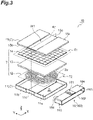
- the power transmission coil device 5 and the power reception coil device 6 according to the first embodiment will be described below with reference to FIGS. 2 to 5B .
- the power transmission coil device 5 and the power reception coil device 6 are disposed at a predetermined distance from each other to face each other in the up-down direction.
- the power transmission coil device 5 is disposed to protrude upward from the road surface G.
- the power reception coil device 6 is attached to, for example, the lower surface of a chassis B of the vehicle V.
- the power transmission coil device 5 and the power reception coil device 6 have, for example, a flat frustum shape or a rectangular parallelepiped shape.
- the power transmission coil device 5 may also be embedded in the road surface G without protruding from the road surface G.
- the power transmission coil device 5 and the power reception coil device 6 are the coil devices 10 that have the same configuration. Accordingly, the power reception coil device 6 will be described as the coil device 10 and the same description will be omitted with regard to the power transmission coil device 5 in some cases.
- the coil device 10 is provided with a housing C including a cover 11 and a base 15 and a belt-shaped fixing member 16 fixing the cover 11 to the base 15.
- the housing C accommodates a coil portion T in an accommodating space (internal space) S formed by the cover 11 and the base 15 when the cover 11is fixed to the base 15.
- the coil portion T is a flat interior part including at least the coil 12 and including a first surface T1 and a second surface T2.
- the coil portion T includes the coil 12, a holding member 13, and a ferrite portion 14.
- the coil 12, the holding member 13, and the ferrite portion 14 are disposed in sequence from the cover 11 to the base 15 (from the second surface T2 to the first surface T1) in the accommodating space S.
- One or both of the holding member 13 and the ferrite portion 14 may be omitted in the coil portion T.
- the cover 11 is a box body disposed on the side of the second surface T2 of the coil portion T and protecting the coil 12, the holding member 13, and the ferrite portion 14.
- the cover 11 may have, for example, a flat rectangular parallelepiped shape including a bottom portion 11a and a side portion (side surface portion of the housing) 11b.
- the bottom portion 11a faces the second surface T2 of the coil portion T.
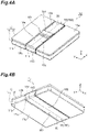
- the middle portion of the bottom portion 11a is a middle portion M2 (refer to FIG. 4B ) of the cover 11 and is the middle portion of the housing C facing the first surface T1 and the second surface T2 of the coil portion T.
- the cover 11 is formed of a non-magnetic and insulating material such as glass fiber reinforced plastic (GFRP).
- the cover 11 includes a groove portion 11c where the fixing member 16 is disposed.
- the groove portion 11c is a recessed portion continuously formed with a predetermined width and a predetermined depth in the bottom portion 11a and the side portion 11b (refer to FIGS. 4A and 4B ).
- the groove portion 11c is formed to pass through the middle portion M2 of the cover 11 along the X direction.
- the groove portion 11c is formed to extend along the Z direction from both X-direction end portions of the groove portion 11c in the bottom portion 11a.
- the predetermined width of the groove portion 11c can be set in accordance with the width of the fixing member 16.
- the predetermined depth of the groove portion 11c can be set in accordance with the thickness of the fixing member 16.
- the predetermined width of the groove portion 11c can be equal to the width of the fixing member 16.
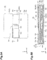
- the predetermined depth of the groove portion 11c can be equal to the thickness of the fixing member 16 (refer to FIG. 5B ).
- the coil 12 is formed by a conductive wire 12a wound in a substantially rectangular spiral shape in the same plane and generates an induced current.
- the coil 12 is a so-called circular coil.
- the circular coil is a coil in which the conductive wire 12a is wound in a planar spiral shape.
- the planar spiral shape is a shape in which the conductive wire is wound from the outside to the inside or from the inside to the outside such that the winding axis is surrounded.
- the conductive wire 12a may be wound in a planar spiral shape in the coil 12, and the coil 12 may have one layer or multiple layers.
- the coil 12 may have various shapes, such as rectangular, circular, and oblong, when seen from the winding axis direction.
- Used as an example of the conductive wire 12a is a Ritz wire in which a plurality of conductor wires insulated from each other are twisted together.
- the conductive wire 12a may be a single wire of copper or aluminum or a bus bar or the like.
- the holding member 13 is a flat plate-shaped member (so-called bobbin) for holding the coil 12.
- the coil 12 may be fitted in a groove portion formed in the holding member 13.
- a material with electrical insulation properties such as silicone and polyphenylene sulfide resin is used as the material of the holding member 13.
- the ferrite portion 14 is, for example, a rectangular flat plate-shaped ferrite core.
- the ferrite portion 14 is a magnetic body and sets the direction of and concentrates magnetic lines of force generated from the coil 12.
- the ferrite portion 14 may be substantially identical to the holding member 13 in shape and size in, for example, a plan view. Any shape and size can be set for the ferrite portion 14 insofar as the ferrite portion 14 fits in the accommodating space that is surrounded by the cover 11 and the base 15.
- the planar shape of the ferrite portion 14 is not limited to a square shape and any shape can be set as the planar shape of the ferrite portion 14.
- the base 15 is a plate-shaped member disposed on the side of the first surface T1 of the coil portion T so that the rigidity of the coil device 10 as a whole is ensured and leakage flux to the outside is shielded.
- the base 15 may also be, for example, a flat plate including a plate portion 15a and a side portion (side surface portion of the housing) 15b.
- the plate portion 15a faces the first surface T1 of the coil portion T.
- the middle portion of the plate portion 15a is a middle portion M1 of the base 15 and is the middle portion of the housing C facing the first surface T1 and the second surface T2 of the coil portion T.
- the base 15 may be composed of, for example, one plate material or a plurality of combined plate materials.
- the shapes of the base 15 in the X direction and the Y direction are, as an example, identical to the shapes of the cover 11 in the X direction and the Y direction (refer to FIGS. 3 , 4A and 4B ).
- the base 15 is non-magnetic and electrically conductive and is formed of a high-rigidity material (such as aluminum and copper).
- the base 15 includes a groove portion 15c where the fixing member 16 is disposed.
- the groove portion 15c is a recessed portion continuously formed with a predetermined width and a predetermined depth in the plate portion 15a and the side portion 15b (refer to FIGS. 4A and 4B ).
- the groove portion 15c is formed to pass through the middle portion M1 of the base 15 along the X direction.
- the groove portion 15c is formed to extend along the Z direction from both X-direction end portions of the groove portion 15c in the plate portion 15a.
- the predetermined width of the groove portion 15c can be set in accordance with the width of the fixing member 16.
- the predetermined depth of the groove portion 15c can be set in accordance with the thickness of the fixing member 16.
- the predetermined width of the groove portion 15c can be equal to the width of the fixing member 16.
- the predetermined depth of the groove portion 15c can be approximately twice the thickness of the fixing member 16 in the plate portion 15a.
- the predetermined depth of the groove portion 15c can be equal to the thickness of the fixing member 16 in the side portion 15b (refer to FIG. 5B ).
- the base 15 has rigidity to the extent that a misalignment of the cover 11 with respect to the base 15 or deformation of the cover 11 can be suppressed when a load acting on the cover 11 is transmitted to the base 15 by the fixing member 16.
- the load acting on the cover 11 include a load for supporting interior parts such as the coil portion T and a load directly acting on the cover 11 from the outside of the coil device 10. In a case where the coil device 10 is attached to the vehicle V such that the cover 11 is on the vertically lower side, for example, the cover 11 being deformed to hang vertically downward can be suppressed.
- the fixing member 16 fixes the cover 11 to the base 15 and transmits a load acting on the cover 11 to the base 15.
- the fixing member 16 includes a first fixing portion 160 disposed at least along the cover 11 on a first outer periphery R1 of the housing C.
- the first outer periphery R1 is an outer periphery of the housing C surrounding the housing C by using the Y direction as an axis and passing through the middle portion M2 of the cover 11 and the middle portion M1 of the base 15.
- the first outer periphery R1 is not particularly limited insofar as the first outer periphery R1 is an outer periphery of the housing C surrounding the cover 11 and the base 15.
- the fixing member 16 is disposed over the entire circumference of the first outer periphery R1.
- the fixing member 16 includes an intermediate portion 162 disposed along the bottom portion 11a of the cover 11, a connecting portion 163 disposed along the side portion 11b of the cover 11 and the side portion 15b of the base 15, and both end portions 164 disposed along the plate portion 15a of the base 15.
- the fixing member 16 is in planar contact with the cover 11 in the intermediate portion 162 and the connecting portion 163.
- the intermediate portion 162 and the connecting portion 163 disperse a load in the places of contact with the cover 11.
- the both end portions 164 transmit a load transmitted from the cover 11 to the base 15 in the places of contact of the intermediate portion 162 and the connecting portion 163 with the cover 11.
- the fixing member 16 is annularly formed by, for example, both longitudinal-direction end portions of an elongated belt-shaped member that has a predetermined width being superposed on and joined to each other in a joining portion 161.
- the fixing member 16 may be configured to practically function as an elongated belt-shaped member that has a predetermined width by a plurality of linear members such as string materials, wires, and wire rods being apposed.
- the material of the fixing member 16 is not particularly limited insofar as the material is electrically non-conductive.
- the material of the fixing member 16 may be an elastic body such as cloth, resin, rubber, and an elastomer, may be GFRP or the like, or can be selected from various materials.
- the fixing member 16 may be directly fixed to the base 15 by, for example, an adhesive (not illustrated), a bolt (not illustrated), or a hook (not illustrated).
- the fixing member 16 may be modified in the form of a fixing member 16X.
- the fixing member 16X is annularly formed by both end portions 164X divided in the middle portion M1 of the base 15 being fixed via a holding tool 165 instead of the joining portion 161 and the both end portions 164 of the fixing member 16.
- the intermediate portion 162 and the connecting portion 163 disperse a load in the places of contact with the cover 11.
- the both end portions 164X transmit a load transmitted from the cover 11 to the base 15 in the places of contact of the intermediate portion 162 and the connecting portion 163 with the cover 11.
- a coil device 10A according to a second embodiment will be described with reference to FIGS. 7 and 8C .
- the coil device 10A differs from the coil device 10 in that the coil device 10A is provided with a base 15A including recessed portions 15d instead of the base 15 and a fixing member 16A including hooking portions 166 that can be hooked on the recessed portions 15d instead of the fixing member 16.
- the base 15A includes the recessed portions 15d respectively disposed in both X-direction end portions of the groove portion 15c of the plate portion 15a.
- the recessed portion 15d is a fixing groove extending in the Y direction and is recessed to, for example, have a hat-shaped section when seen perpendicularly to the Y direction.
- the fixing member 16A includes the intermediate portion 162 along the bottom portion 11a including the surface of the cover 11 facing the second surface T2, the connecting portions 163 extending along the side portions 15b of the base 15 from the intermediate portion 162, and both end portions 164A disposed along the plate portion 15a of the base 15 from the connecting portions 163.
- the both end portions 164A include the hooking portions 166 disposed at positions corresponding to the recessed portions 15d of the base 15A.
- the hooking portion 166 is a projecting rib protruding downward and extending in the Y direction. Accordingly, the hooking portion 166 can be hooked on the recessed portion 15d of the base 15A.
- the hooking portions 166 of the both end portions 164A are caught by and hooked on the recessed portions 15d of the base 15 once, for example, the fixing member 16A is pushed in from the cover 11 side with respect to the cover 11 and the base 15A with the coil portion T accommodated in the accommodating space S.
- an X-direction movement of the both end portions 164A is regulated, and thus a load transmitted from the cover 11 is transmitted to the base 15A and the cover 11 is fixed to the base 15A.
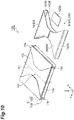
- a coil device 10B according to a third embodiment will be described with reference to FIGS. 9 and 10 .
- the coil device 10B differs from the coil device 10 in that the coil device 10B is provided with a cover 11B including the groove portion 11c partially expanded in width instead of the cover 11, a base 15B including the groove portion 15c partially expanded in width instead of the base 15, and a fixing member 16B partially expanded in width instead of the fixing member 16.
- the width of the fixing member 16B in the middle portions M1 and M2 of the housing C facing the first surface T1 and the second surface T2 of the coil portion T is smaller than the width of the fixing member 16B in the side portion 11b and the side portion 15b (side surface portions of the housing C).
- the width of the fixing member 16B is the dimension of the fixing member 16B in a direction crossing the extension direction of the first outer periphery R1.
- the width of an intermediate portion 162B along the cover 11B increases from the middle portion M2 of the cover 11B toward the side portion 11b.
- the intermediate portion 162B has a minimum width in the middle portion M2 of the cover 11B.
- the width of both end portions 164B along the base 15B increases from the middle portion M1 of the base 15B toward the side portions 15b.
- the both end portions 164B have a minimum width in the middle portion M1 of the base 15B.
- a connecting portion 163B covers almost the whole of the side portion 11b and the side portion 15b.
- the fixing member 16B is annularly formed by joining in a joining portion 161B.
- the widths of the groove portion 11c of the cover 11B and the groove portion 15c of the base 15B are set in accordance with the width of the fixing member 16B. In other words, the width of the groove portion 11c in the middle portion M2 of the cover 11B increases toward the side portion 11b of the cover 11B. The width of the groove portion 15c in the middle portion M1 of the base 15B increases toward the side portion 15b of the base 15B.
- the fixing member 16B as described above is in planar contact with the cover 11B in the intermediate portion 162B and the connecting portion 163B.
- the intermediate portion 162B and the connecting portion 163B disperse a load in the places of contact with the cover 11B.
- the both end portions 164B transmit a load transmitted from the cover 11B to the base 15B in the places of contact of the intermediate portion 162B and the connecting portion 163B with the cover 11B.
- the fixing member 16B may be modified in the form of a fixing member 16BX.
- both end portions 164BX divided in the middle portion M1 of the base 15B are fixed via a holding tool 165B.
- the intermediate portion 162B and the connecting portion 163B disperse a load in the places of contact with the cover 11B.
- the both end portions 164BX transmit a load transmitted from the cover 11B to the base 15B in the places of contact of the intermediate portion 162B and the connecting portion 163B with the cover 11B.
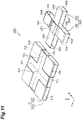
- a coil device 10C according to the third embodiment will be described with reference to FIGS. 11 , 12A and 12B .
- the coil device 10C differs from the coil device 10 in that the coil device 10C is provided with a cover 11C further including the groove portion 11c along a second outer periphery R2 instead of the cover 11, a base 15C further including the groove portion 15c along the second outer periphery R2 instead of the base 15, and a fixing member 16C further including a second fixing portion 260 disposed along the second outer periphery R2 instead of the fixing member 16.
- the fixing member 16C includes the first fixing portion 160 and the second fixing portion 260 surrounding the cover 11C and the base 15C, extending along the second outer periphery R2 of the housing C crossing the first outer periphery R1, and disposed along at least the cover 11C.
- the second outer periphery R2 can be an outer periphery of the housing C surrounding the housing C by using the X direction as an axis and passing through the middle portion M2 of the cover 11C and the middle portion M1 of the base 15C. In other words, the second outer periphery R2 can be orthogonal to the first outer periphery R1.
- the first fixing portion 160 of the fixing member 16C is similar in configuration to the first fixing portion 160 of the fixing member 16.
- the second fixing portion 260 is disposed over the entire circumference of the second outer periphery R2.
- the second fixing portion 260 includes an intermediate portion 262 disposed along the bottom portion 11a of the cover 11C, connecting portions 263 disposed along the side portion 11b of the cover 11C and the side portion 15b of the base 15C, and both end portions 264 disposed along the plate portion 15a of the base 15C.
- the cover 11C includes the groove portions 11c where the first fixing portion 160 and the second fixing portion 260 of the fixing member 16C are disposed.
- the groove portions 11c can be formed to pass through the middle portion M2 of the cover 11C along the X direction and the Y direction in the bottom portion 11a.
- the groove portions 11c are respectively formed to extend along the Z direction from both X-direction end portions and both Y-direction end portions of the groove portions 11c in the bottom portion 11a.
- the base 15C includes the groove portions 15c where the first fixing portion 160 and the second fixing portion 260 of the fixing member 16C are disposed.
- the groove portions 15c can be formed to pass through the middle portion M1 of the base 15C along the X direction and the Y direction in the plate portion 15a.
- the groove portions 15c are respectively formed to extend along the Z direction from both X-direction end portions and both Y-direction end portions of the groove portions 15c in the plate portion 15a.
- the first fixing portion 160 is annularly formed by, for example, an elongated belt-shaped member that has a predetermined width being joined to each other in the joining portion 161 where both longitudinal-direction end portions of the first fixing portion 160 are superposed on each other.
- the second fixing portion 260 is annularly formed by, for example, an elongated belt-shaped member that has a predetermined width being joined to each other in a joining portion 261 where both longitudinal-direction end portions of the second fixing portion 260 are superposed on each other.
- the first fixing portion 160 and the second fixing portion 260 may be formed integrally or separately.
- the fixing member 16C as described above is in planar contact with the cover 11C in the intermediate portion 162, the intermediate portion 262, the connecting portion 163, and the connecting portion 263.
- the intermediate portion 162, the connecting portion 163, the intermediate portion 262, and the connecting portion 263 disperse a load in the places of contact with the cover 11C.
- the both end portions 164 and the both end portions 264 transmit a load transmitted from the cover 11C to the base 15C in the places of contact with the cover 11C.
- the fixing member 16C may be modified in the form of a fixing member 16CX.
- the both end portions 164X and both end portions 264X divided in the middle portion M1 of the base 15C are fixed via a holding tool 165CX.
- the intermediate portion 162B and the connecting portion 163B disperse a load in the places of contact with the cover 11C.
- the both end portions 164X and the both end portions 264X transmit a load transmitted from the cover 11C to the base 15C in the places of contact of the intermediate portion 162, the connecting portion 163, the intermediate portion 262, and the connecting portion 263 with the cover 11C.
- the fixing member 16C may further include a fixing portion disposed along at least the cover 11C on an outer periphery of the housing C surrounding the housing C by using a direction other than the X direction and the Y direction as an axis.
- the fixing . member 16C may be directly fixed to the base 15C by, for example, an adhesive (not illustrated), a bolt (not illustrated), or a hook (not illustrated).
- the hooking portions 166 of the both end portions 164 and the both end portions 264 may be caught by and hooked on the recessed portions 15d of the base 15C by, for example, the hooking portions 166 being respectively disposed in the both end portions 164 and the both end portions 264 and the recessed portions 15d being respectively disposed at positions in the base 15C corresponding to the hooking portions 166.
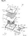
- a coil device 10D according to a fourth embodiment will be described with reference to FIGS. 14 to 16 .
- the coil device 10D differs from the coil device 10B in that the coil device 10D is provided with a cover 11D including a through hole 11h instead of the cover 11B, a holding member 13D including a through hole 13h instead of the holding member 13, a ferrite portion 14D including a through hole 14h instead of the ferrite portion 14, a base 15D including a through hole 15h instead of the base 15B, and a fixing member 16D including a pair of first fixing portions 160D instead of the fixing member 16B.
- the fixing member 16D includes the pair of first fixing portions 160D disposed across the through holes 11h, 13h, 14h, and 15h and fixing the cover 11D to the base 15D.
- the first fixing portion 160D is shaped by, for example, the fixing member 16B being divided into two in the X direction near the middle in the X direction and a pair of inner fixing portions 167 being disposed in the divided places.
- the through hole 11h into which the pair of inner fixing portions 167 can be inserted is formed in the middle portion M2 of the cover 11D.
- the through hole 13h into which the pair of inner fixing portions 167 can be inserted is formed in the middle portion of the holding member 13D.
- the through hole 14h into which the pair of inner fixing portions 167 can be inserted is formed in the middle portion of the ferrite portion 14D.
- the through hole 15h into which the pair of inner fixing portions 167 can be inserted is formed in the middle portion M1 of the base 15D.
- the pair of inner fixing portions 167 inserted into the through holes 11h, 13h, 14h, and 15h interconnect the middle portion M2 of the cover 11D and the middle portion Ml of the base 15D on the first outer periphery R1.
- the through holes 11h, 13h, 14h, and 15h are, for example, long holes that are long in one direction along the XY plane (Y direction in the present embodiment).
- Each of the pair of first fixing portions 160D is annularly formed by, for example, joining in a pair of joining portions 161D as is the case with the joining portion 161.
- the pair of first fixing portions 160D are disposed symmetrically to each other across the through holes 11h and 15h on the first outer periphery R1 in a state where the pair of inner fixing portions 167 are inserted into the through holes 11h, 13h, 14h, and 15h. Accordingly, the pair of first fixing portions 160D as a whole are disposed practically over the entire circumference of the first outer periphery R1.
- the fixing member 16D may be directly fixed to the base 15D by, for example, an adhesive (not illustrated), a bolt (not illustrated), or a hook (not illustrated).
- the fixing member 16D as described above is in planar contact with the cover 11D in a pair of intermediate portions 162D and a pair of connecting portions 163D.
- the pair of intermediate portions 162D and the pair of connecting portions 163D disperse a load in the places of contact with the cover 11D.
- a pair of both end portions 164D transmit a load transmitted from the cover 11D to the base 15D in the places of contact with the cover 11D.
- the pair of inner fixing portions 167 transmit a load transmitted from the middle portion M2 of the cover 11D to the middle portion M1 of the base 15D by interconnecting the middle portion M2 of the cover 11D and the middle portion M1 of the base 15D. As a result, the tightening strength of the fixing member 16D is further dispersed.
- the fixing member 16D may be modified in the form of a fixing member 16DX including a pair of first fixing portions 160DX.
- first fixing portions 160DX both end portions 164DX divided near the middle portion M1 of the base 15D are fixed via a holding tool 165D.
- the pair of intermediate portions 162D and the pair of connecting portions 163D disperse a load in the places of contact with the cover 1 ID.
- the pair of both end portions 164DX transmit a load transmitted from the cover 11D to the base 15D in the places of contact with the cover 11D.
- the pair of inner fixing portions 167 transmit a load transmitted from the middle portion M2 of the cover 11D to the middle portion M1 of the base 15D by interconnecting the middle portion M2 of the cover 11D and the middle portion M1 of the base 15D.
- a coil device 10E according to a fifth embodiment will be described with reference to FIGS. 17 , 18A and 18B .
- the coil device 10E differs from the coil device 10 in that the coil device 10E is provided with a cover 11E where fixing portions 16E are integrally formed instead of the cover 11 and the fixing member 16 and a base 15E from which the groove portion 15c is omitted instead of the base 15.
- the cover 11E has a box shape and includes a bottom surface 11m and side surfaces 11p, 11r, 11s, and 11t.
- the cover 11E includes the four fixing portions 16E disposed to extend from respective sides 11u of the side surfaces 11p, 11r, 11s, and 11t.
- the fixing portions 16E fix the cover 11E to the base 15E by being fixed on the plate portion 15a of the base 15E.
- the cover 11E ensures the rigidity of the coil device 10E as a whole.
- the cover 11E is formed of a high-rigidity, non-magnetic, and electrically non-conductive material (such as high-strength polyethylene terephthalate (PET) resin and silicone rubber).
- PET polyethylene terephthalate
- the cover 11E has rigidity to the extent that a misalignment of the cover 11E with respect to the base 15E or deformation of the cover 11E can be suppressed when a load acting on the cover 11E is transmitted to the base 15E by the fixing portion 16E.
- Examples of the load acting on the cover 11E include a load for supporting interior parts such as the coil portion T and a load directly acting on the cover 11E from the outside of the coil device 10E. In a case where the coil device 10E is attached to the vehicle V such that the cover 11E is on the vertically lower side, for example, the cover 11E being deformed to hang vertically downward can be suppressed.
- the fixing portions 16E are fixed on the plate portion 15a of the flat plate-shaped base 15E including the surface of the base 15E opposite to the coil portion T.
- the shape of each of the fixing portions 16E is, for example, similar to the triangle that is obtained by the bottom surface 11m being divided into four equal parts by a pair of diagonal lines. This triangle includes a pair of side portions 16a and a top portion 16b.
- the side portions 16a are capable of extending along the side portions 16a of the adjacent fixing portions 16E such that the gap between the side portions 16a of the adjacent fixing portions 16E widens toward the top portions 16b of the fixing portions 16E.
- the top portions 16b are capable of being disposed at a predetermined distance from the top portions 16b of the adjacent fixing portions 16E.
- the shape of the fixing portion 16E is not limited thereto, and the fixing portion 16E may have any shape insofar as the fixing portion 16E can be fixed on the plate portion 15a.
- the accommodating space S is formed by the fixing portion 16E of the cover 11E being disposed along the plate portion 15a of the base 15E.
- the cover 11E accommodates the coil portion T such that the coil portion T as a whole is enclosed along with the base 15E.
- the fixing portion 16E has a strength retention function for the coil device 10E and a function as an exterior cover. Accordingly, the cover 11E and the base 15E are the housing C accommodating the coil portion T in the accommodating space S formed by the cover 11E and the base 15E.
- the cover 11E is fixed to the base 15E by the fixing portion 16E as described above being fixed on the plate portion 15a of the base 15E.
- a load acting on the cover 1 IE is dispersed in the box-shaped cover 11E as a whole and transmitted to the base 15E via the fixing portion 16E.
- the fixing member 16 to 16D fixing the cover 11 to 11D to the base 15 to 15D includes the first fixing portion 160 disposed along at least the cover 11 to lID on the first outer periphery R1 of the housing C.
- This fixing member 16 to 16D is in linear or planar contact with the cover 11 to 11D.
- the fixing member 16 to 16D has a belt shape. As a result, the fixing member 16 to 16D is in planar contact with the cover 11 to 11D, and thus the load in the portion of contact between the fixing member 16 to 16D and the cover 11 to 11D is easily dispersed.
- the width of the fixing member 16B and 16D in the middle portions Ml and M2 of the housing C facing the first surface T1 and the second surface T2 of the coil portion T is smaller than the width of the fixing member 16B and 16D in the side portion 11b and the side portion 15b as the side surface portions of the housing C.
- the fixing member 16B and 16D covers a wide range of the side portion 11b and the side portion 15b of the housing C, and thus the cover 11B and 11D can be reliably fixed to the base 15B and 15D.
- the first outer periphery R1 passes through the middle portion M1 of the base 15 to 15D and the middle portion M2 of the cover 11 to 11D.
- the fixing member 16 to 16D is disposed to pass through at least one of the middle portion M1 of the base 15 to 15D and the middle portion M2 of the cover 11 to 11D on the first outer periphery R1 of the housing C. Accordingly, a load acting on the cover 11 to 11D is easily transmitted to the base 15 to 15D.
- the fixing member 16 and 16B to 16D is disposed over the entire circumference of the first outer periphery R1 and includes the joining portion 161, 161B, 261, and 161D for joining the fixing member 16 and 16B to 16D, respectively, with each other.
- the fixing member 16 and 16B to 16D is disposed over the entire circumference of the first outer periphery R1 by the joining portion 161, 161B, 261, and 161D that join the fixing member 16 and 16B to 16D, respectively, with each other, and thus parts for joining the fixing member 16 and 16B to 16D, respectively, with each other can be omitted.
- the fixing member 16A includes the intermediate portion 162 along the bottom portion 11a of the cover 11 facing the second surface T2, the both end portions 164A along the plate portion 15a of the base 15 facing the first surface T1, and the connecting portions 163 interconnecting the intermediate portion 162 and the both end portions 164A, and the both end portions 164 of the fixing member 16A include the hooking portions 166 that can be hooked on the recessed portions 15d of the base 15A.
- the cover 11 can be easily fixed to the base 15A simply by the hooking portion 166 being hooked on the recessed portion 15d of the base 15A.
- the fixing member 16C further includes the second fixing portion 260 surrounding the cover 11C and the base 15C, extending along the second outer periphery R2 of the housing C crossing the first outer periphery R1, and disposed along at least the cover 11C.
- the cover 11C is fixed to the base 15C by the second fixing portion 260 as well as the first fixing portion 160. Accordingly, the cover 11C can be reliably fixed to the base 15C.
- the first fixing portion 160 includes the inner fixing portion 167 disposed to interconnect the middle portion M1 of the base 15D on the first outer periphery R1 and the middle portion M2 of the cover 11D on the first outer periphery R1. As a result, a load acting on the middle portion M2 of the cover 11D is easily transmitted to the middle portion M1 of the base 15D via the inner fixing portion 167.
- the housing C includes the groove portions 11c and 15c where the fixing member 16 to 16D is disposed. As a result, a misalignment of the fixing member 16 to 16D from the housing C can be suppressed.
- the cover 11E is fixed to the base 15E by the fixing portions 16E of the cover 11E being fixed on the plate portion 15a including the surface of the base 15E that is on the side opposite to the coil portion T.
- a load acting on the cover 11E is dispersed in the box-shaped cover 11E as a whole and transmitted to the base 15E via the fixing portion 16E. Accordingly, load concentration in the cover 11E can be suppressed even if, for example, the load of the coil portion T acts on the cover 11E.
- the fixing member 16 is a belt-shaped member in the above-described embodiments
- the fixing member 16 may be, for example, a wire rod instead.
- the fixing member 16 is in linear contact with the cover 11, and thus the load in the portion of contact between the fixing member 16 and the cover 11 is easily dispersed.
- the fixing member 16 may be configured by, for example, a plurality of wire rods being apposed in a direction crossing the first outer periphery R1. Also in this case, the fixing member 16 is practically in planar contact with the cover 11, and thus the load in the portion of contact between the fixing member 16 and the cover 11 is easily dispersed.
- the coil 12 is a so-called circular coil.
- the coil 12 may be a solenoid-type coil in which the conductive wire 12a is wound around the axis.
- the coil device 10 has been described based on the power reception coil device 6 attached to the vehicle V as an example.
- the coil device 10 can also be adopted for the power transmission coil device 5 installed on the road surface G.
- the fixing member 16 is capable of suppressing a misalignment of the cover 11 with respect to the base 15 attributable to a load acting on the coil device 10. Examples of the load in this case include a load at a time when a tire of the vehicle V is in contact with the cover 11 of the power transmission coil device 5 (coil device 10) before or after stopping of the vehicle V traveling on the ground at a predetermined position.
- the present invention is not limited to this aspect.
- the coil device 10 according to the present disclosure is also applicable to a coil device used in a wireless power transfer system for charging a battery of a movable object other than the vehicle such as an underwater vehicle.
Landscapes
- Engineering & Computer Science (AREA)
- Power Engineering (AREA)
- Transportation (AREA)
- Mechanical Engineering (AREA)
- Computer Networks & Wireless Communication (AREA)
- Electric Propulsion And Braking For Vehicles (AREA)
- Housings And Mounting Of Transformers (AREA)
- Charge And Discharge Circuits For Batteries Or The Like (AREA)
- Coils Or Transformers For Communication (AREA)
- Current-Collector Devices For Electrically Propelled Vehicles (AREA)
Claims (8)
- Spulenvorrichtung (10, 10A, 10B, 10C, 10D, 10E), die zum Einsatz in einem drahtlosen Energieübertragungssystem ausgeführt ist, wobei sie umfasst:einen Spulenabschnitt (T), der wenigstens eine Spule (12) enthält, die aus einem leitenden Draht (12a) besteht;ein Gehäuse (C), das eine plattenförmige Basis (15, 15A, 15B, 15C, 15D, 15E), die an einer Seite einer ersten Fläche (T1) des Spulenabschnitts (T) angeordnet ist, sowie eine Abdeckung (11, 11B, 11C, 11D, 11E) enthält, die an einer Seite einer dem Spulenabschnitt (T) gegenüberliegenden zweiten Fläche (T2) angeordnet ist und den Spulenabschnitt (T) in einem Innenraum (S) aufnimmt, der durch die Basis (15, 15A, 15B, 15C, 15D, 15E) und die Abdeckung (11) gebildet wird, wobei die erste Fläche (T1) und die zweite Fläche (T2) parallel zu einer horizontalen Ebene sind, die sich in einer X- und Y-Richtung erstreckt; sowieein Befestigungselement (16, 16A, 16B, 16C, 16D, 16X, 16BX, 16CX, 16DX), das die Abdeckung (11, 11B, 11C, 11D, 11E) an der Basis (15, 15A, 15B, 15C, 15D, 15E) befestigt,wobei das Befestigungselement (16, 16A, 16B, 16C, 16D, 16X, 16BX, 16CX, 16DX) gegenüberliegende Endabschnitte (164, 164A, 164B, 164D, 164X, 164BX, 164DX, 264, 264X) aufweist, das Befestigungselement einen ersten Befestigungsabschnitt (161, 161B, 161D), der wenigstens entlang der Abdeckung (11, 11B, 11C, 11D, 11E, 11) an einem ersten Außenumfang (R1) des Gehäuses (C) angeordnet ist, der die Basis (15, 15A, 15B, 15C, 15D, 15E) und die Abdeckung (11, 11B, 11C, 11D, 11E) umschließt,die Spulenvorrichtung (10, 10A, 10B, 10C, 10D, 10E) so ausgeführt ist, dass sie so an einem Fahrzeug (V) angebracht wird, dass, in einer vertikalen Z-Richtung des Fahrzeugs gesehen, sich die Abdeckung (11) an einer unteren Seite befindet und sich die Basis an einer oberen Seite an das Fahrzeug angrenzend befindet,das Befestigungselement (16, 16A, 16B, 16C, 16D, 16X, 16BX, 16CX, 16DX) einen Zwischenabschnitt (162, 162B, 162D, 262), der entlang eines Bodenabschnitts (11a) der Abdeckung (11) angeordnet ist, wobei der Bodenabschnitt der zweiten Fläche T2 des Spulenabschnitts zugewandt ist, einen Verbindungsabschnitt (163, 163B, 163D, 263), der sich in der Z-Richtung erstreckt und entlang eines Seitenabschnitts (11b) der Abdeckung (11) sowie eines Seitenabschnitts (15b) der Basis (15) angeordnet ist und beide Endabschnitte (164, 164A, 164B, 164D, 164X, 164BX, 164DX, 264, 264X) enthält, die entlang eines Plattenabschnitts (15a) der Basis (15) angeordnet sind,wobei der erste Außenumfang (R1) ein Außenumfang ist, der das Gehäuse (C) in der Y-Richtung als einer Achse zum Umschließen umschließt,der Außenumfang durch einen mittleren Abschnitt (M2) der Abdeckung (11) sowie einen mittleren Abschnitt (M1) der Basis (15) hindurch verläuft, und der mittlere Abschnitt (M1) der Abdeckung sowie der mittlere Abschnitt (M2) der Basis der ersten Fläche (T1) und der zweiten Fläche (T2) zugewandt sind, unddas Befestigungselement (16, 16A, 16B, 16C, 16D, 16X, 16BX, 16CX, 16DX) in dem Zwischenabschnitt (162, 162B, 162D, 262) und in dem Verbindungsabschnitt (163, 163B, 163D, 263) in flächigem Kontakt mit der Abdeckung (11) ist.
- Spulenvorrichtung nach Anspruch 1, wobei das Befestigungselement (16, 16A, 16B, 16C, 16D, 16X, 16BX, 16CX, 16DX) eine Bandform hat.
- Spulenvorrichtung nach Anspruch 2, wobei eine Breite des Befestigungselementes (16B, 16D, 16BX, 16DX) in einem mittleren Abschnitt des Gehäuses (C), der der ersten Fläche (T1) und der zweiten Fläche (T) des Spulenabschnitts (T) zugewandt ist, kleiner ist als die Breite des Befestigungselementes (16B, 16D, 16BX, 16DX) in einem Seitenflächenabschnitt des Gehäuses (C).
- Spulenvorrichtung nach einem der Ansprüche 1 bis 3, wobei das Befestigungselement (16, 16B, 16C, 16D) über einen gesamten Umfang des ersten Außenumfangs (R1) angeordnet ist und einen verbindenden Abschnitt (161, 161B, 161D) enthält, der das Befestigungselement (16, 16B, 16C, 16D) verbindet.
- Spulenvorrichtung nach einem der Ansprüche 1 bis 3, wobei
die beiden Endabschnitte (164, 164A, 164B, 164D, 164X, 164BX, 164DX) Einhakabschnitte (166) enthalten, die an der Basis (15, 15A, 15B, 15C, 15D, 15E) eingehakt werden können. - Spulenvorrichtung nach einem der Ansprüche 1 bis 5, wobei das Befestigungselement (16C) des Weiteren einen zweiten Befestigungsabschnitt (260) enthält, der sich entlang eines zweiten Außenumfangs (R2) des Gehäuses (C) erstreckt, der die Basis (15C) und die Abdeckung (11C) umschließt und den ersten Außenumfang (R1) kreuzt, und wenigstens entlang der Abdeckung (11C) angeordnet ist.
- Spulenvorrichtung nach Anspruch 1, wobei das Befestigungselement (16D) einen inneren Befestigungsabschnitt (167) aufweist, der so angeordnet ist, dass er den mittleren Abschnitt (M1) der Basis (11D) an dem ersten Außenumfang (R1) und den mittleren Abschnitt (M2) der Abdeckung (15D) an dem ersten Außenumfang (R1) miteinander verbindet.
- Spulenvorrichtung nach einem der Ansprüche 1 bis 7, wobei das Gehäuse (C) einen Nutabschnitt (11c) enthält, in dem das Befestigungselement (16, 16A, 16B, 16C, 16D, 16X, 16BX, 16CX, 16DX) angeordnet ist.
Applications Claiming Priority (2)
| Application Number | Priority Date | Filing Date | Title |
|---|---|---|---|
| JP2016135128A JP6589759B2 (ja) | 2016-07-07 | 2016-07-07 | コイル装置 |
| PCT/JP2017/021526 WO2018008331A1 (ja) | 2016-07-07 | 2017-06-09 | コイル装置 |
Publications (3)
| Publication Number | Publication Date |
|---|---|
| EP3483906A1 EP3483906A1 (de) | 2019-05-15 |
| EP3483906A4 EP3483906A4 (de) | 2020-01-22 |
| EP3483906B1 true EP3483906B1 (de) | 2022-08-10 |
Family
ID=60912593
Family Applications (1)
| Application Number | Title | Priority Date | Filing Date |
|---|---|---|---|
| EP17823938.0A Active EP3483906B1 (de) | 2016-07-07 | 2017-06-09 | Spulenvorrichtung |
Country Status (5)
| Country | Link |
|---|---|
| US (1) | US11211189B2 (de) |
| EP (1) | EP3483906B1 (de) |
| JP (1) | JP6589759B2 (de) |
| CN (1) | CN109074954B (de) |
| WO (1) | WO2018008331A1 (de) |
Families Citing this family (7)
| Publication number | Priority date | Publication date | Assignee | Title |
|---|---|---|---|---|
| FR3092283B1 (fr) * | 2019-01-31 | 2021-01-15 | Psa Automobiles Sa | Véhicule à motorisation électrique équipé d’un dispositif de recharge par induction comprenant une pluralité de bobines d’induction dans un bac de protection à déformation programmée |
| DE102019212151A1 (de) * | 2019-08-13 | 2021-02-18 | Mahle International Gmbh | Energieübertrager für eine berührungslose Energieübertragung und Traktionsakkumulator-Ladesystem |
| JP7398670B2 (ja) * | 2020-03-23 | 2023-12-15 | パナソニックIpマネジメント株式会社 | 表示制御装置、表示制御方法、及び、車両 |
| DE102020209282A1 (de) * | 2020-07-23 | 2022-01-27 | Mahle International Gmbh | Induktionsbaugruppe einer induktiven Ladevorrichtung |
| JP7698509B2 (ja) * | 2021-08-06 | 2025-06-25 | 株式会社大林組 | 舗装構造及び、舗装方法 |
| JP2023157786A (ja) * | 2022-04-15 | 2023-10-26 | 新電元工業株式会社 | コイルユニット |
| US12606035B2 (en) * | 2022-12-06 | 2026-04-21 | Volkswagen Aktiengesellschaft | Devices, systems, and methods for wireless vehicle charging |
Citations (1)
| Publication number | Priority date | Publication date | Assignee | Title |
|---|---|---|---|---|
| WO2014179320A1 (en) * | 2013-05-01 | 2014-11-06 | Qualcomm Incorporated | Vehicle charging pad having reduced thickness |
Family Cites Families (20)
| Publication number | Priority date | Publication date | Assignee | Title |
|---|---|---|---|---|
| JPS5115053Y2 (de) * | 1971-06-22 | 1976-04-21 | ||
| JPS5115053A (ja) | 1974-07-22 | 1976-02-06 | Teijin Ltd | Tokirihanashisochi |
| JPS5544342Y2 (de) * | 1975-02-20 | 1980-10-17 | ||
| JPH073125U (ja) * | 1993-06-08 | 1995-01-17 | トップ電子株式会社 | コモンモードチョークコイル部品およびemiノイズフィルタ |
| JPH118142A (ja) * | 1997-06-18 | 1999-01-12 | Tokin Corp | 電子部品 |
| JP4356844B2 (ja) | 2006-10-05 | 2009-11-04 | 昭和飛行機工業株式会社 | 非接触給電装置 |
| JP4209437B2 (ja) | 2006-11-10 | 2009-01-14 | 三菱重工業株式会社 | 移動体の非接触給電装置及びその保護装置 |
| US20090230163A1 (en) * | 2008-03-13 | 2009-09-17 | Chi-Tsai Chang | Adhesive tape dispenser |
| KR101040662B1 (ko) | 2009-04-06 | 2011-06-13 | 한국과학기술원 | 전기자동차용 초박형 급전장치와 집전장치 |
| JP5240786B2 (ja) | 2009-08-25 | 2013-07-17 | 国立大学法人埼玉大学 | 非接触給電装置 |
| JP5562797B2 (ja) * | 2010-10-18 | 2014-07-30 | 昭和飛行機工業株式会社 | 非接触給電装置の1次コイル配設構造 |
| US20120218068A1 (en) | 2011-02-28 | 2012-08-30 | Equos Research Co., Ltd. | Antenna |
| CN204117820U (zh) * | 2011-03-09 | 2015-01-21 | 松下电器产业株式会社 | 非接触充电模块、非接触充电器以及电子设备 |
| JP5244250B1 (ja) | 2012-03-28 | 2013-07-24 | パナソニック株式会社 | 給電装置 |
| JP2014075899A (ja) | 2012-10-04 | 2014-04-24 | Nissan Motor Co Ltd | 非接触給電装置 |
| JP6417713B2 (ja) | 2014-05-22 | 2018-11-07 | 株式会社Ihi | コイル装置 |
| JP6131915B2 (ja) | 2014-06-11 | 2017-05-24 | トヨタ自動車株式会社 | 送電装置および受電装置 |
| JP2016010171A (ja) | 2014-06-20 | 2016-01-18 | 矢崎総業株式会社 | 非接触給電装置における受電側ユニット |
| JP6371130B2 (ja) * | 2014-06-20 | 2018-08-08 | 矢崎総業株式会社 | コイルユニット |
| JP6485080B2 (ja) | 2015-02-02 | 2019-03-20 | 株式会社Ihi | コイル装置の取付構造およびコイル装置 |
-
2016
- 2016-07-07 JP JP2016135128A patent/JP6589759B2/ja active Active
-
2017
- 2017-06-09 CN CN201780024668.1A patent/CN109074954B/zh active Active
- 2017-06-09 WO PCT/JP2017/021526 patent/WO2018008331A1/ja not_active Ceased
- 2017-06-09 US US16/313,922 patent/US11211189B2/en active Active
- 2017-06-09 EP EP17823938.0A patent/EP3483906B1/de active Active
Patent Citations (1)
| Publication number | Priority date | Publication date | Assignee | Title |
|---|---|---|---|---|
| WO2014179320A1 (en) * | 2013-05-01 | 2014-11-06 | Qualcomm Incorporated | Vehicle charging pad having reduced thickness |
Also Published As
| Publication number | Publication date |
|---|---|
| WO2018008331A1 (ja) | 2018-01-11 |
| JP6589759B2 (ja) | 2019-10-16 |
| US11211189B2 (en) | 2021-12-28 |
| CN109074954B (zh) | 2020-07-24 |
| US20190252105A1 (en) | 2019-08-15 |
| CN109074954A (zh) | 2018-12-21 |
| EP3483906A1 (de) | 2019-05-15 |
| JP2018006672A (ja) | 2018-01-11 |
| EP3483906A4 (de) | 2020-01-22 |
Similar Documents
| Publication | Publication Date | Title |
|---|---|---|
| EP3483906B1 (de) | Spulenvorrichtung | |
| US10960770B2 (en) | Vehicle | |
| JP6743432B2 (ja) | コイル装置 | |
| JP6369493B2 (ja) | 給電コイルユニット、ワイヤレス給電装置およびワイヤレス電力伝送装置 | |
| JP5293851B2 (ja) | コイルユニット及び非接触給電システム | |
| US9787138B2 (en) | Power reception device and power transmission device | |
| JP5846302B2 (ja) | 車両 | |
| US20150137590A1 (en) | Power reception device, power transmission device, and vehicle | |
| EP2849314A1 (de) | Für berührungslosen stromempfang konfiguriertes fahrzeug | |
| US20170063155A1 (en) | Power Supply Device | |
| JP6370558B2 (ja) | コイルユニット及びそれを有する給電システム | |
| EP2860841A1 (de) | Stromempfangende Vorrichtung und Stromversorgungsvorrichtung | |
| US10332677B2 (en) | Power reception device and power transmission device | |
| WO2014156014A1 (ja) | 非接触充電装置 | |
| US11001156B2 (en) | Charging device having an induction coil stitched to a surface of a cross-laid structure | |
| JP2017212302A (ja) | コイル装置、非接触給電装置、及び非接触受電装置 | |
| JP6301675B2 (ja) | コイルユニット及びそれを有する給電システム | |
| KR20150070831A (ko) | 차량의 무선충전 송신 모듈 |
Legal Events
| Date | Code | Title | Description |
|---|---|---|---|
| STAA | Information on the status of an ep patent application or granted ep patent |
Free format text: STATUS: THE INTERNATIONAL PUBLICATION HAS BEEN MADE |
|
| PUAI | Public reference made under article 153(3) epc to a published international application that has entered the european phase |
Free format text: ORIGINAL CODE: 0009012 |
|
| STAA | Information on the status of an ep patent application or granted ep patent |
Free format text: STATUS: REQUEST FOR EXAMINATION WAS MADE |
|
| 17P | Request for examination filed |
Effective date: 20190205 |
|
| AK | Designated contracting states |
Kind code of ref document: A1 Designated state(s): AL AT BE BG CH CY CZ DE DK EE ES FI FR GB GR HR HU IE IS IT LI LT LU LV MC MK MT NL NO PL PT RO RS SE SI SK SM TR |
|
| AX | Request for extension of the european patent |
Extension state: BA ME |
|
| DAV | Request for validation of the european patent (deleted) | ||
| DAX | Request for extension of the european patent (deleted) | ||
| A4 | Supplementary search report drawn up and despatched |
Effective date: 20191220 |
|
| RIC1 | Information provided on ipc code assigned before grant |
Ipc: H01F 27/02 20060101ALI20191216BHEP Ipc: H01F 38/14 20060101AFI20191216BHEP Ipc: H02J 7/00 20060101ALI20191216BHEP Ipc: H02J 50/10 20160101ALI20191216BHEP |
|
| STAA | Information on the status of an ep patent application or granted ep patent |
Free format text: STATUS: EXAMINATION IS IN PROGRESS |
|
| 17Q | First examination report despatched |
Effective date: 20200915 |
|
| GRAP | Despatch of communication of intention to grant a patent |
Free format text: ORIGINAL CODE: EPIDOSNIGR1 |
|
| STAA | Information on the status of an ep patent application or granted ep patent |
Free format text: STATUS: GRANT OF PATENT IS INTENDED |
|
| INTG | Intention to grant announced |
Effective date: 20220419 |
|
| GRAS | Grant fee paid |
Free format text: ORIGINAL CODE: EPIDOSNIGR3 |
|
| GRAA | (expected) grant |
Free format text: ORIGINAL CODE: 0009210 |
|
| STAA | Information on the status of an ep patent application or granted ep patent |
Free format text: STATUS: THE PATENT HAS BEEN GRANTED |
|
| AK | Designated contracting states |
Kind code of ref document: B1 Designated state(s): AL AT BE BG CH CY CZ DE DK EE ES FI FR GB GR HR HU IE IS IT LI LT LU LV MC MK MT NL NO PL PT RO RS SE SI SK SM TR |
|
| REG | Reference to a national code |
Ref country code: AT Ref legal event code: REF Ref document number: 1511163 Country of ref document: AT Kind code of ref document: T Effective date: 20220815 Ref country code: CH Ref legal event code: EP |
|
| REG | Reference to a national code |
Ref country code: IE Ref legal event code: FG4D |
|
| REG | Reference to a national code |
Ref country code: DE Ref legal event code: R096 Ref document number: 602017060564 Country of ref document: DE |
|
| REG | Reference to a national code |
Ref country code: NL Ref legal event code: MP Effective date: 20220810 |
|
| REG | Reference to a national code |
Ref country code: LT Ref legal event code: MG9D |
|
| PG25 | Lapsed in a contracting state [announced via postgrant information from national office to epo] |
Ref country code: SE Free format text: LAPSE BECAUSE OF FAILURE TO SUBMIT A TRANSLATION OF THE DESCRIPTION OR TO PAY THE FEE WITHIN THE PRESCRIBED TIME-LIMIT Effective date: 20220810 Ref country code: RS Free format text: LAPSE BECAUSE OF FAILURE TO SUBMIT A TRANSLATION OF THE DESCRIPTION OR TO PAY THE FEE WITHIN THE PRESCRIBED TIME-LIMIT Effective date: 20220810 Ref country code: PT Free format text: LAPSE BECAUSE OF FAILURE TO SUBMIT A TRANSLATION OF THE DESCRIPTION OR TO PAY THE FEE WITHIN THE PRESCRIBED TIME-LIMIT Effective date: 20221212 Ref country code: NO Free format text: LAPSE BECAUSE OF FAILURE TO SUBMIT A TRANSLATION OF THE DESCRIPTION OR TO PAY THE FEE WITHIN THE PRESCRIBED TIME-LIMIT Effective date: 20221110 Ref country code: NL Free format text: LAPSE BECAUSE OF FAILURE TO SUBMIT A TRANSLATION OF THE DESCRIPTION OR TO PAY THE FEE WITHIN THE PRESCRIBED TIME-LIMIT Effective date: 20220810 Ref country code: LV Free format text: LAPSE BECAUSE OF FAILURE TO SUBMIT A TRANSLATION OF THE DESCRIPTION OR TO PAY THE FEE WITHIN THE PRESCRIBED TIME-LIMIT Effective date: 20220810 Ref country code: LT Free format text: LAPSE BECAUSE OF FAILURE TO SUBMIT A TRANSLATION OF THE DESCRIPTION OR TO PAY THE FEE WITHIN THE PRESCRIBED TIME-LIMIT Effective date: 20220810 Ref country code: FI Free format text: LAPSE BECAUSE OF FAILURE TO SUBMIT A TRANSLATION OF THE DESCRIPTION OR TO PAY THE FEE WITHIN THE PRESCRIBED TIME-LIMIT Effective date: 20220810 |
|
| REG | Reference to a national code |
Ref country code: AT Ref legal event code: MK05 Ref document number: 1511163 Country of ref document: AT Kind code of ref document: T Effective date: 20220810 |
|
| PG25 | Lapsed in a contracting state [announced via postgrant information from national office to epo] |
Ref country code: PL Free format text: LAPSE BECAUSE OF FAILURE TO SUBMIT A TRANSLATION OF THE DESCRIPTION OR TO PAY THE FEE WITHIN THE PRESCRIBED TIME-LIMIT Effective date: 20220810 Ref country code: IS Free format text: LAPSE BECAUSE OF FAILURE TO SUBMIT A TRANSLATION OF THE DESCRIPTION OR TO PAY THE FEE WITHIN THE PRESCRIBED TIME-LIMIT Effective date: 20221210 Ref country code: HR Free format text: LAPSE BECAUSE OF FAILURE TO SUBMIT A TRANSLATION OF THE DESCRIPTION OR TO PAY THE FEE WITHIN THE PRESCRIBED TIME-LIMIT Effective date: 20220810 Ref country code: GR Free format text: LAPSE BECAUSE OF FAILURE TO SUBMIT A TRANSLATION OF THE DESCRIPTION OR TO PAY THE FEE WITHIN THE PRESCRIBED TIME-LIMIT Effective date: 20221111 |
|
| PG25 | Lapsed in a contracting state [announced via postgrant information from national office to epo] |
Ref country code: SM Free format text: LAPSE BECAUSE OF FAILURE TO SUBMIT A TRANSLATION OF THE DESCRIPTION OR TO PAY THE FEE WITHIN THE PRESCRIBED TIME-LIMIT Effective date: 20220810 Ref country code: RO Free format text: LAPSE BECAUSE OF FAILURE TO SUBMIT A TRANSLATION OF THE DESCRIPTION OR TO PAY THE FEE WITHIN THE PRESCRIBED TIME-LIMIT Effective date: 20220810 Ref country code: ES Free format text: LAPSE BECAUSE OF FAILURE TO SUBMIT A TRANSLATION OF THE DESCRIPTION OR TO PAY THE FEE WITHIN THE PRESCRIBED TIME-LIMIT Effective date: 20220810 Ref country code: DK Free format text: LAPSE BECAUSE OF FAILURE TO SUBMIT A TRANSLATION OF THE DESCRIPTION OR TO PAY THE FEE WITHIN THE PRESCRIBED TIME-LIMIT Effective date: 20220810 Ref country code: CZ Free format text: LAPSE BECAUSE OF FAILURE TO SUBMIT A TRANSLATION OF THE DESCRIPTION OR TO PAY THE FEE WITHIN THE PRESCRIBED TIME-LIMIT Effective date: 20220810 Ref country code: AT Free format text: LAPSE BECAUSE OF FAILURE TO SUBMIT A TRANSLATION OF THE DESCRIPTION OR TO PAY THE FEE WITHIN THE PRESCRIBED TIME-LIMIT Effective date: 20220810 |
|
| REG | Reference to a national code |
Ref country code: DE Ref legal event code: R097 Ref document number: 602017060564 Country of ref document: DE |
|
| PG25 | Lapsed in a contracting state [announced via postgrant information from national office to epo] |
Ref country code: SK Free format text: LAPSE BECAUSE OF FAILURE TO SUBMIT A TRANSLATION OF THE DESCRIPTION OR TO PAY THE FEE WITHIN THE PRESCRIBED TIME-LIMIT Effective date: 20220810 Ref country code: EE Free format text: LAPSE BECAUSE OF FAILURE TO SUBMIT A TRANSLATION OF THE DESCRIPTION OR TO PAY THE FEE WITHIN THE PRESCRIBED TIME-LIMIT Effective date: 20220810 |
|
| PLBE | No opposition filed within time limit |
Free format text: ORIGINAL CODE: 0009261 |
|
| STAA | Information on the status of an ep patent application or granted ep patent |
Free format text: STATUS: NO OPPOSITION FILED WITHIN TIME LIMIT |
|
| PG25 | Lapsed in a contracting state [announced via postgrant information from national office to epo] |
Ref country code: AL Free format text: LAPSE BECAUSE OF FAILURE TO SUBMIT A TRANSLATION OF THE DESCRIPTION OR TO PAY THE FEE WITHIN THE PRESCRIBED TIME-LIMIT Effective date: 20220810 |
|
| 26N | No opposition filed |
Effective date: 20230511 |
|
| PG25 | Lapsed in a contracting state [announced via postgrant information from national office to epo] |
Ref country code: SI Free format text: LAPSE BECAUSE OF FAILURE TO SUBMIT A TRANSLATION OF THE DESCRIPTION OR TO PAY THE FEE WITHIN THE PRESCRIBED TIME-LIMIT Effective date: 20220810 |
|
| PG25 | Lapsed in a contracting state [announced via postgrant information from national office to epo] |
Ref country code: MC Free format text: LAPSE BECAUSE OF FAILURE TO SUBMIT A TRANSLATION OF THE DESCRIPTION OR TO PAY THE FEE WITHIN THE PRESCRIBED TIME-LIMIT Effective date: 20220810 |
|
| PG25 | Lapsed in a contracting state [announced via postgrant information from national office to epo] |
Ref country code: MC Free format text: LAPSE BECAUSE OF FAILURE TO SUBMIT A TRANSLATION OF THE DESCRIPTION OR TO PAY THE FEE WITHIN THE PRESCRIBED TIME-LIMIT Effective date: 20220810 |
|
| REG | Reference to a national code |
Ref country code: CH Ref legal event code: PL |
|
| REG | Reference to a national code |
Ref country code: BE Ref legal event code: MM Effective date: 20230630 |
|
| GBPC | Gb: european patent ceased through non-payment of renewal fee |
Effective date: 20230609 |
|
| PG25 | Lapsed in a contracting state [announced via postgrant information from national office to epo] |
Ref country code: LU Free format text: LAPSE BECAUSE OF NON-PAYMENT OF DUE FEES Effective date: 20230609 |
|
| REG | Reference to a national code |
Ref country code: IE Ref legal event code: MM4A |
|
| PG25 | Lapsed in a contracting state [announced via postgrant information from national office to epo] |
Ref country code: LU Free format text: LAPSE BECAUSE OF NON-PAYMENT OF DUE FEES Effective date: 20230609 |
|
| PG25 | Lapsed in a contracting state [announced via postgrant information from national office to epo] |
Ref country code: IE Free format text: LAPSE BECAUSE OF NON-PAYMENT OF DUE FEES Effective date: 20230609 |
|
| PG25 | Lapsed in a contracting state [announced via postgrant information from national office to epo] |
Ref country code: IE Free format text: LAPSE BECAUSE OF NON-PAYMENT OF DUE FEES Effective date: 20230609 Ref country code: CH Free format text: LAPSE BECAUSE OF NON-PAYMENT OF DUE FEES Effective date: 20230630 Ref country code: GB Free format text: LAPSE BECAUSE OF NON-PAYMENT OF DUE FEES Effective date: 20230609 |
|
| PG25 | Lapsed in a contracting state [announced via postgrant information from national office to epo] |
Ref country code: IT Free format text: LAPSE BECAUSE OF FAILURE TO SUBMIT A TRANSLATION OF THE DESCRIPTION OR TO PAY THE FEE WITHIN THE PRESCRIBED TIME-LIMIT Effective date: 20220810 Ref country code: FR Free format text: LAPSE BECAUSE OF NON-PAYMENT OF DUE FEES Effective date: 20230630 Ref country code: BE Free format text: LAPSE BECAUSE OF NON-PAYMENT OF DUE FEES Effective date: 20230630 |
|
| PG25 | Lapsed in a contracting state [announced via postgrant information from national office to epo] |
Ref country code: BG Free format text: LAPSE BECAUSE OF FAILURE TO SUBMIT A TRANSLATION OF THE DESCRIPTION OR TO PAY THE FEE WITHIN THE PRESCRIBED TIME-LIMIT Effective date: 20220810 |
|
| PG25 | Lapsed in a contracting state [announced via postgrant information from national office to epo] |
Ref country code: BG Free format text: LAPSE BECAUSE OF FAILURE TO SUBMIT A TRANSLATION OF THE DESCRIPTION OR TO PAY THE FEE WITHIN THE PRESCRIBED TIME-LIMIT Effective date: 20220810 |
|
| PGFP | Annual fee paid to national office [announced via postgrant information from national office to epo] |
Ref country code: DE Payment date: 20250520 Year of fee payment: 9 |
|
| PG25 | Lapsed in a contracting state [announced via postgrant information from national office to epo] |
Ref country code: CY Free format text: LAPSE BECAUSE OF FAILURE TO SUBMIT A TRANSLATION OF THE DESCRIPTION OR TO PAY THE FEE WITHIN THE PRESCRIBED TIME-LIMIT; INVALID AB INITIO Effective date: 20170609 |
|
| PG25 | Lapsed in a contracting state [announced via postgrant information from national office to epo] |
Ref country code: HU Free format text: LAPSE BECAUSE OF FAILURE TO SUBMIT A TRANSLATION OF THE DESCRIPTION OR TO PAY THE FEE WITHIN THE PRESCRIBED TIME-LIMIT; INVALID AB INITIO Effective date: 20170609 |
|
| PG25 | Lapsed in a contracting state [announced via postgrant information from national office to epo] |
Ref country code: TR Free format text: LAPSE BECAUSE OF FAILURE TO SUBMIT A TRANSLATION OF THE DESCRIPTION OR TO PAY THE FEE WITHIN THE PRESCRIBED TIME-LIMIT Effective date: 20220810 |