EP3483893A1 - Methods of selecting surgical implants and related devices - Google Patents
Methods of selecting surgical implants and related devices Download PDFInfo
- Publication number
- EP3483893A1 EP3483893A1 EP18205252.2A EP18205252A EP3483893A1 EP 3483893 A1 EP3483893 A1 EP 3483893A1 EP 18205252 A EP18205252 A EP 18205252A EP 3483893 A1 EP3483893 A1 EP 3483893A1
- Authority
- EP
- European Patent Office
- Prior art keywords
- dimensional parameters
- anatomical surface
- medical implants
- providing
- digital image
- Prior art date
- Legal status (The legal status is an assumption and is not a legal conclusion. Google has not performed a legal analysis and makes no representation as to the accuracy of the status listed.)
- Pending
Links
Images


Classifications
-
- A—HUMAN NECESSITIES
- A61—MEDICAL OR VETERINARY SCIENCE; HYGIENE
- A61B—DIAGNOSIS; SURGERY; IDENTIFICATION
- A61B5/00—Measuring for diagnostic purposes; Identification of persons
- A61B5/103—Detecting, measuring or recording devices for testing the shape, pattern, colour, size or movement of the body or parts thereof, for diagnostic purposes
- A61B5/107—Measuring physical dimensions, e.g. size of the entire body or parts thereof
-
- G—PHYSICS
- G16—INFORMATION AND COMMUNICATION TECHNOLOGY [ICT] SPECIALLY ADAPTED FOR SPECIFIC APPLICATION FIELDS
- G16H—HEALTHCARE INFORMATICS, i.e. INFORMATION AND COMMUNICATION TECHNOLOGY [ICT] SPECIALLY ADAPTED FOR THE HANDLING OR PROCESSING OF MEDICAL OR HEALTHCARE DATA
- G16H30/00—ICT specially adapted for the handling or processing of medical images
-
- A—HUMAN NECESSITIES
- A61—MEDICAL OR VETERINARY SCIENCE; HYGIENE
- A61B—DIAGNOSIS; SURGERY; IDENTIFICATION
- A61B17/00—Surgical instruments, devices or methods, e.g. tourniquets
- A61B17/56—Surgical instruments or methods for treatment of bones or joints; Devices specially adapted therefor
- A61B17/58—Surgical instruments or methods for treatment of bones or joints; Devices specially adapted therefor for osteosynthesis, e.g. bone plates, screws, setting implements or the like
- A61B17/68—Internal fixation devices, including fasteners and spinal fixators, even if a part thereof projects from the skin
- A61B17/80—Cortical plates, i.e. bone plates; Instruments for holding or positioning cortical plates, or for compressing bones attached to cortical plates
-
- A—HUMAN NECESSITIES
- A61—MEDICAL OR VETERINARY SCIENCE; HYGIENE
- A61B—DIAGNOSIS; SURGERY; IDENTIFICATION
- A61B34/00—Computer-aided surgery; Manipulators or robots specially adapted for use in surgery
- A61B34/25—User interfaces for surgical systems
-
- A—HUMAN NECESSITIES
- A61—MEDICAL OR VETERINARY SCIENCE; HYGIENE
- A61B—DIAGNOSIS; SURGERY; IDENTIFICATION
- A61B17/00—Surgical instruments, devices or methods, e.g. tourniquets
- A61B17/56—Surgical instruments or methods for treatment of bones or joints; Devices specially adapted therefor
- A61B2017/568—Surgical instruments or methods for treatment of bones or joints; Devices specially adapted therefor produced with shape and dimensions specific for an individual patient
-
- A—HUMAN NECESSITIES
- A61—MEDICAL OR VETERINARY SCIENCE; HYGIENE
- A61B—DIAGNOSIS; SURGERY; IDENTIFICATION
- A61B34/00—Computer-aided surgery; Manipulators or robots specially adapted for use in surgery
- A61B34/10—Computer-aided planning, simulation or modelling of surgical operations
- A61B2034/108—Computer aided selection or customisation of medical implants or cutting guides
-
- A—HUMAN NECESSITIES
- A61—MEDICAL OR VETERINARY SCIENCE; HYGIENE
- A61F—FILTERS IMPLANTABLE INTO BLOOD VESSELS; PROSTHESES; DEVICES PROVIDING PATENCY TO, OR PREVENTING COLLAPSING OF, TUBULAR STRUCTURES OF THE BODY, e.g. STENTS; ORTHOPAEDIC, NURSING OR CONTRACEPTIVE DEVICES; FOMENTATION; TREATMENT OR PROTECTION OF EYES OR EARS; BANDAGES, DRESSINGS OR ABSORBENT PADS; FIRST-AID KITS
- A61F2250/00—Special features of prostheses classified in groups A61F2/00 - A61F2/26 or A61F2/82 or A61F9/00 or A61F11/00 or subgroups thereof
- A61F2250/0058—Additional features; Implant or prostheses properties not otherwise provided for
- A61F2250/006—Additional features; Implant or prostheses properties not otherwise provided for modular
- A61F2250/0064—Sets comprising a plurality of prosthetic parts of different sizes
-
- A—HUMAN NECESSITIES
- A61—MEDICAL OR VETERINARY SCIENCE; HYGIENE
- A61F—FILTERS IMPLANTABLE INTO BLOOD VESSELS; PROSTHESES; DEVICES PROVIDING PATENCY TO, OR PREVENTING COLLAPSING OF, TUBULAR STRUCTURES OF THE BODY, e.g. STENTS; ORTHOPAEDIC, NURSING OR CONTRACEPTIVE DEVICES; FOMENTATION; TREATMENT OR PROTECTION OF EYES OR EARS; BANDAGES, DRESSINGS OR ABSORBENT PADS; FIRST-AID KITS
- A61F2250/00—Special features of prostheses classified in groups A61F2/00 - A61F2/26 or A61F2/82 or A61F9/00 or A61F11/00 or subgroups thereof
- A61F2250/0058—Additional features; Implant or prostheses properties not otherwise provided for
- A61F2250/0078—Gender-specific, e.g. different for male and female patients
Definitions
- the present disclosure relates to medical procedures and, more particular, to medical implants and related methods, devices, and computer program products.
- An orthopedic implant (such as a bone plate) may be used, for example, to support a damaged bone.
- the implant may be fabricated from stainless steel and/or titanium alloys, and a plurality of screw holes through the implant may allow fixation to the bone using bone screws. The surgeon may thus expose the damaged bone and screw the implant to the bone.
- an implant for a particular bone may be manufactured in different sizes and/or shapes.
- the unique anatomy and injury pattern of each individual patient may thus require selection of a properly sized and contoured implant from a set of many available sizes and contours for the same type of implant. Positive treatment outcomes may correlate with well-fitting implants.
- the surgeon may select from a number of implant sizes/shapes during surgery to fit the bone being repaired.
- the selection of a particular implant may involve the surgeon visually inspecting the exposed bone surface during surgery and selecting one or more of the implants based on the visual inspection. Selecting a best-fitting implant from among many implants may thus be a time-consuming and imprecise process for the surgeon, thereby increasing a time required to perform the surgery.
- the surgeon may try to fit multiple implants to the bone before selecting the final implant resulting in waste due to contamination of implants that are tried but not used.
- Some embodiments of the present disclosure are directed to methods to identify a medical implant from a plurality of medical implants to be fixed to an anatomical surface.
- Dimensional parameters for each of the plurality of medical implants may be provided, and dimensional parameters corresponding to the anatomical surface may be provided.
- the dimensional parameters for each of the plurality of medical implants may be compared with the dimensional parameters corresponding to the anatomical surface, and one of the medical implants may be selected from the plurality of medical implants based on comparing the dimensional parameters for each of the plurality of medical implants with the dimensional parameters corresponding to the anatomical surface.
- An identification of the medical implant selected from the plurality of medical implants may be provided through a user interface. Related devices and computer program products are also discussed.
- Figure 1 is a block diagram illustrating elements of selection device 100 configured to provide assistance in the selection of a medical implant (e.g., an orthopedic implant, such as a bone plate) according to some embodiments of inventive concepts.
- selection device 100 may include user interface 101, processor 103, memory 105, camera 107, and/or wired/wireless interface 109, and processor 103 may be coupled with each of user interface 101, memory 105, camera 107, and/or wired/wireless interface 109.
- Selection device 100 of Figure 1 may be implemented using a smartphone, a tablet computer, a laptop computer, a desktop computer, a dedicated computing device, etc., configured to perform operations to select an medical implant according to embodiments herein.
- Selection device 100 may be a smartphone, tablet computer, laptop computer, or desktop computer running an app/software configured to perform operations discussed herein. According to some other embodiments, selection device 100 may be provided in/as a head mounted device worn by the surgeon. According to still other embodiments, selection device 100 may be integrated with other operating room equipment.
- operations of the selection device 100 of Figure 1 may be performed by processor 103, user interface 101, wired/wireless interface 109, and/or camera 107.
- processor 103 may accept data regarding the implant surface through camera 107 and/or wired/wireless interface 109, select one of a plurality of implants, and provide an identification of the selected implant through user interface 101.
- modules may be stored in memory 105, and these modules may provide instructions so that when instructions of a module are executed by processor 103, processor 103 performs respective operations (e.g., operations discussed below with respect to Figure 17 ).
- processor circuit 103 may be defined to include memory so that a separate memory is not required.
- camera 107 may be used to capture images, where the images are used by processor 103 to provide/generate dimensional parameters corresponding to an anatomical surface (e.g., a bone surface) to which the implant (e.g., an orthopedic implant such as a bone plate) is to be fixed.
- images or other data may be captured outside selection device 100 and received by processor 103 through wired/wireless interface 109, or dimensional parameters corresponding to the anatomical surface may be generated outside selection device 100 and received by processor 103 through wired/wireless interface 109, such that camera 107 may be omitted.
- Wired/wireless interface 109 may include a wired interface (e.g., a Universal Serial Bus or USB port), a short range wireless interface (e.g., a BlueTooth transceiver, a WiFi transceiver, etc.), and/or a long range wireless interface (e.g., a cellular radio telephone transceiver).
- a wired interface e.g., a Universal Serial Bus or USB port
- a short range wireless interface e.g., a BlueTooth transceiver, a WiFi transceiver, etc.
- a long range wireless interface e.g., a cellular radio telephone transceiver
- user interface 101 may include one or more of a plurality of input/output devices.
- keypad 101a one or more buttons 101b, touch screen 101c, and/or microphone 101e may be provided to accept user input
- touch screen 101c and/or speaker 101d may provide user output (e.g., an identification of a selected medical input).
- a conventional display non-touch screen
- Camera 107 may be operated responsive to user input through keypad 101a, button(s) 101b, touch screen 101c, and/or microphone 101e.
- methods, devices, and/or computer program products may be provided to log the unique morphology of an intended implant site (e.g., bone surface) intraoperatively and to apply best-fit algorithms to assist selection of a most suitable implant.
- an intended implant site e.g., bone surface
- best-fit algorithms to assist selection of a most suitable implant.
- a best-fitting anatomically contoured bone plate may be selected from a plurality of bone plates according to some embodiments.
- a surgeon may use selection device 100 with the following operations of templating, imaging, and image analysis to select a particular implant from a plurality of implants of varying sizes and shapes/contours. While selection of a clavicle plate is discussed by way of example in the following embodiments, embodiments of inventive concepts may be applied for other medical/orthopedic implants and/or bone plates.
- the surgeon may first surgically expose the site of intended plate fixation (e.g., a surface of clavicle 201), and then the surgeon may shape a malleable template to fit a 3-dimensional contour of the intended implant site.
- a desired length of malleable template material 203a may be broken off (by hand) to represent a desired length of the implant, and the surgeon may shape the resulting malleable template 203b to fit a 3-dimensional contour of the exposed implant site as shown in Figure 2B .
- the resulting shaped template 203b is shown in the two (substantially orthogonal) views of Figures 3A and 3B .
- the template 203b may have lengthwise segments 205 with lengths equal to the spacing between implant screw holes of the implant.
- the template material 203a may preferentially break at notches 207 between these segments, and each segment 205 may be marked with lines 209 perpendicular with respect to a trajectory of the segment.
- These lines 209 contrast with the template itself to facilitate image recognition.
- Lines 209 (or other markings) may be provided on only one of the two primary faces of the template to ensure reading of a proper orientation of the template (and not an inverted orientation).
- lines 209 may be provided on a face away from the bone to reduce obstruction of lines 209 due to blood or other material resulting from contact with the exposed bone.
- lines 209 may be provided on a face adjacent to the bone so that the marked face of the template more closely matches the contour of the bone.
- one end of template 203b may have a larger segment 211 to indicate/represent a specific end of the implant.
- the larger segment 211 of Figure 4A may represent a metaphyseal region 411 of bone plate 401 of Figure 4B .
- This larger segment 211 of template 203b may alternatively be broken off if not wanted.
- lines 209 may be provided on template 203b to correspond to screw holes 409 of bone plate 401.
- template 203b may be placed in imaging cradle 501 with sides 503 and 505 that are 90 degrees perpendicular (orthogonal) as shown in Figure 5 .
- These perpendicular surfaces 503 and 505 may have horizontal and/or vertical reference lines or other markings to facilitate image analysis by providing information about scaling and orientation of template 203b.
- imaging cradle 501 With its V-shaped trough, imaging cradle 501 may enable complimentary imaging of template 203b at orthogonal angles, as shown in Figure 6 .
- the orthogonal images of template 203b may be captured with camera 107 of selection device 100 of Figure 1 from positions 100a and 100b as shown in Figure 6 .
- selection device 100 may be implemented using a smart phone, a tablet computer, or other similar device with on-board software.
- the orthogonal images may be captured by a camera or other imaging device outside selection device 100, and the orthogonal images (or data relating thereto) may be provided through wired/wireless interface 109 of selection device 100 to processor 103.
- Center position and/or focal distance may be calibrated using aligning markers 511a-b, 515a-b, and 519a-b on image cradle 501.
- the angle of 90 degree projection images may be assisted using gyroscopic and/or accelerometer feedback that may be commonly available in smart phone devices used as selection device 100.
- selection device 100 including camera 107 may be held in positions 100a and 100b to take the respective images of Figures 7A and 7B .
- desired orientations of the orthogonal images may be provided.
- one camera 107 from selection device 100 (or one camera outside of selection device 100) may be used to take the orthogonal images of Figures 7A and 7B from positions 100a and 100b.
- separate cameras may be mounted (permanently or detachably) in positions 100a and 100b to take the images of Figures 7A and 7B without requiring manual alignment.
- An image capture device may include imaging cradle 501 and two cameras that are mounted in positions 100a and 100b to capture the images of Figures 7A and 7B , and the resulting images (or data such as dimensional parameters relating thereto) may be provided to selection device 100 through wired/wireless interface 109.
- Figure 8A shows a view of imaging cradle 501 taken from camera position 101b with alignment markers 515a-b and 519a-b.
- Figure 8B shows alignment of markers 515a and 519
- Figure 8C shows alignment of markers 515b and 519b as will occur when the camera is properly aligned at position 101b.
- the image can be taken with assurance that the camera is properly positioned.
- processor 103 may reject the image and generate a request (provided through a screen/display and/or speaker of user interface 101) for the user to retake the image.
- processor 103 may use such visual misalignment from markers 515a, 519a, 515b, and/or 519b to adjust the image and/or data derived therefrom.
- a mirror 521 (or multiple) may be added to image cradle 501 to enable two (or more) projection angles to be captured by camera 107 of selection device 100 with one image from one angle.
- Mirror 521 may be a non-reversing mirror. Position and distance may again be calibrated with markers on the cradle as discussed above with respect to Figures 8A-C .
- Use of mirror 521 may allow the orthogonal images of template 203b to be captured in one photo instead of two.
- the one image may include both a direct image of template 203b corresponding to the image of Figure 7B and a reflection 203b' of template 203b corresponding to the image of Figure 7A .
- camera 107 of selection device 100 may be used in Figure 9 , or a separate camera may be used with the image or data relating thereto being provided to processor 103 through wired/wireless interface 109. According to some other embodiments, a separate camera may be mounted with respect to cradle 501 to maintain a desired alignment.
- a head-mounted camera worn by the surgeon may be used to capture the shape of template 203b.
- a tracking system associated with such a head-mounted camera may provide a pose/orientation of the head-mounted camera relative to the imaging cradle 501 or holder for the implant and can provide/ensure that frames for analysis are captured at 90° or any desired angle for analysis.
- the surgeon could place visual markers (such as reflective fiducial markers) at the anatomical site (e.g., on the exposed bone surface).
- Reflective fiducial markers could be tracked stereophotogrammetrically using tracking cameras, and their locations detected in 3D (3-dimensional) space. These 3D surface points could be analyzed similarly to template points and used by processor 103 to select the appropriate implant.
- surgical ink may be used wherein the surgical ink has a property/properties that cause it to selectively adhere to bone and not to surrounding soft tissue.
- Such ink could be detectable using visual tracking or could be radio-opaque, detectable using x-rays.
- Photos or radiographs of the bone with adhered ink could be processed by processor 103 to detect the bone surface contours. Selected points along the contours could be analyzed by processor 103 similarly to template points to select an appropriate implant.
- fitting operations discussed below may be used by processor 101.
- Image analysis may then be performed by processor 103 using the images of Figures 7A and 7B , or using the combined image resulting from Figure 9 (or using other images or related data).
- a software application on the device e.g., an Android app, an iOS app, etc.
- processor 103 may map lines 209 to 3D space.
- Figure 10A illustrates an example of processor 103 autodetecting lines 209 from the image of template 203b in Figure 7A
- Figure 10B illustrates an example of processor 103 autodetecting lines 209 from the image of template 203b in Figure 7B .
- Processor 103 may then fit a spline through the midpoint of each line 209 as shown in Figures 11A and 11B .
- processor 103 may then generate prompts for questions relevant to the surgical procedure, such as anatomical placement (e.g., superior vs anterior).
- Processor 103 may provide the prompts/questions visually through a touch screen or other display of user interface 101 and/or audibly through a speaker of user interface 101.
- processor 103 may follow a best-fit algorithm to match the spline that is associated with template 203b or other method of surface geometry detection with a library or lookup table of splines corresponding to sizes/curvatures of implants available for the procedure.
- processor 103 may then provide a recommendation to the user (e.g., surgeon) regarding the implant with the best-fitting spline.
- the recommendation may include an identification of the selected implant (e.g., a part number), a quantitative closeness of fit (e.g., 0% to 100%), and/or next-best alternatives.
- processor 103 may also suggest where to bend the implant for a better fit, such as between two specific screw holes.
- Processor 103 could provide (on a display such as touch screen 101c or an external monitor) a graphic of the selected plate overlaid on a graphic of the template with arrows indicating where and how much to bend the plate to achieve a better fit.
- the recommendation(s) may be provided visually through a touch screen or other display of user interface 101 and/or audibly through a speaker of user interface 101.
- Another embodiment may use the bending template to define and apply all necessary bending to a straight plate. That is, the curvature defined by the template and read from the optical or other sensing algorithm would then be applied to a straight plate either manually or automatically.
- the processor 103 could provide (on a display such as touch screen 101c or an external monitor) a graphic of the desired curvature with arrows indicating locations and magnitudes of necessary bends. Processor 103 could also show an actual size "blueprint" of the plate in its final form that could be printed or shown actual size on a monitor.
- the system could also assist the surgeon or technician in determining whether starting from a straight plate is a better decision than starting from a pre-bent plate and further bending the plate or back-bending it.
- the surgeon or technician could periodically hold the plate up to the template to check whether the desired curvature was achieved.
- Such an on-screen template might be a better visual guide for the surgeon than the physical template that was laid on bone because it may have thickness, hole spacing and general appearance more similar to the actual plate than the template itself.
- processor 103 could electronically feed information on the locations and magnitudes of bends through wired/wireless interface to an automatic bending device.
- the bending device would activate a bending mechanism that could include computer-controlled rollers, clamps, and/or actuators that would apply the desired bending to the straight plate so that it best matches the template.
- selection device 101 and/or methods thereof may thus automate implant selection during surgery.
- Using such automation may reduce human error, for example, due to a surgeon overlooking and/or misjudging a best-fitting implant, and using such automation may provide quantitative evaluation to augment subjective human judgment.
- each implant that is tried but not used may be thereafter unusable due to contamination from contact to the implant site.
- Virtual fitting of implants according to methods/devices herein may spare unused implants from unnecessary contamination at the surgical site, thereby reducing waste.
- assisted implant selection using methods/devices herein may also reduce the time of the procedure, thereby reducing time that the patient is under anesthesia, benefitting both the surgical team and patient. By improving initial selection of the implant, bending of implants to fit the patient's anatomy may be reduced. Because excessive bending of an implant may weaken the implant, a reduction in bending may reduce a risk of implant failure.
- Methods, devices, and computer program products discussed herein may thus provide a combination of speed of selection and initial accuracy of fit that is not attainable using manual selection. Such speed and accuracy can reduce the time required for surgery, reduce the time that a patient is subject to anesthesia, improve a fit of the implant, and improve the ultimate patient outcome. Moreover, by providing coordinates incrementally for both the template and for the available implants, an efficiency of the comparisons may be improved thereby improving an efficiency of operations of processor 103 to improve a computer-related technology.
- clavicle plate also referred to as an implant selection software may be provided using a Windows-based interface or a smartphone/tablet app.
- Image processing may include detecting curvature of template 203b (also referred to as a plate surrogate) in 2 planes and extracting the 3D shape parameters for comparison to a database of implant shapes/sizes.
- VTK, Qt, Open-CV and other open-source options may be used by processor 103 to detect colors and contours from photo images.
- a Structured Query Language SQL database may be used to store a library of information regarding shapes, dimensions, etc., regarding the available implants.
- Such a database may be stored in memory 105 of selection device 100, or the database may be stored external to selection device 100 with processor 103 accessing information from the database through wired/wireless interface 109.
- processor 103 may automatically process and reorient the images using alignment marks, because orientations of the images from different cameras (of different types) cannot be guaranteed and because there may be uncertainty due to variations in how the user holds the device while taking the photo(s).
- Alignment marks according to some embodiments are discussed above with respect to Figures 6 , 8A-C, and 9 . According to some other embodiments, alignment may be provided using marks illustrated in Figure 12 .
- alignment marks G1 and G2 and alignment marks Y3 and Y4 may be used for one image of template 203b, and alignment marks Y1 and Y2 and alignment marks R1 and R2 may be used for another image of template 203b.
- These different colored alignment marks may be used to specify left-right-up-down, and these markings may be autodetected by processor 103 using Open-CV color masking operations.
- the alignment marks of Figure 12 may also be used to distinguish a series of shots from one another to reduce/prevent accidental loading of duplicate shots instead of a valid pair.
- one side of image cradle 501 may display yellow and green alignment marks (half circles that form circular dots when properly aligned), and the other side of image cradle 501 may display yellow and red alignment marks (half circles that form circular dots when properly aligned).
- lines may extend from the intersection of the two sides 503 and 505, for example, to provide scale.
- half circles at the intersection of the sides may be spaced apart by 178 mm
- half circles at the top of cradle 501 e.g., G1 and Y3
- half circles at the top of cradle 501 may have a smaller diameter than half circles at the intersection of sides (e.g., Y2 and R2) because the half circles at the intersection of sides (e.g., Y2 and R2) will be further from the camera when alignment is performed and the image is taken.
- Alignment using this arrangement of alignment half circles may facilitate/force the user to take photos from a distance of about 35 cm from template 203b. Having this focal distance as a known value while inter-dot distance is also known may allow scaling of pixels to millimeters. Additionally, the known spacing of vertical blue lines may be 1.0 cm to provide a secondary check of the scaling. This information can be used to determine a length of template 203b.
- Figures 14A and 14B provide the resulting orthogonal images of template 203b taken using image cradle 501 with the alignment markers of Figure 12 .
- processor 103 may join the segment locations together and fit the segment locations with a spline.
- Processor 103 may calculate and render splines, for example, using VTK.
- Figures 15A, 15B, and 15C are screenshots showing a spline of 10 points joined together with a cylinder. According to some embodiments, it may be possible to grab each white spherical handle with a left mouse click and drag to adjust its position. It may also be possible to change the perspective view by clicking and dragging on the screen anywhere other than handle locations.
- processor 103 may adjust handle positions to modify a fit factor and also possibly the selection of best-fitting plate. Accordingly, it may be a useful feature to enable the user (surgeon) to proactively explore possibilities for plates/implants. For example, if the user makes the end of the plate a little more curvy, processor 103 may suggest a different plate.
- processor 103 may render images on a display of user interface 101 as flat strips joined by spheres instead of cylinders to represent actual plates. Moreover, processor 103 may only allow the user to move handles laterally on the display while keeping the longitudinal spacing between handles constant to facilitate easier comparison of the spline with a database of implant splines. Processor 103 may also use a data structure for passing spline points to code that compares the spline points to stored splines in a database.
- FIG. 16A and 16B different layouts may be provided for the database of implants.
- Processor 103 may then evaluate x,y values of the template at fixed increments of z and compare these x,y values against x,y values stored in the database for the different available implants.
- the z increment should be fine enough to capture the curvature of the plate without having to store an excessive number of values. For example, 5 mm increments may be used. Since plates may have different lengths (in addition to different curves/contours), the number of entries evaluated and compared may depend on the desired plate length. Table 1 below shows an example for a 50 mm plate.
- processor 103 may query the database and measure the average vector distance from the measured 9 incremental points (i.e., points 2-10) relative to each the corresponding points stored in database entries for plates with matching length (or close to the same length).
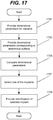
- selection device 100 to identify a medical implant (e.g., a bone plate) from a plurality of medical implants will now be discussed with reference to the flow chart of Figure 17 .
- a medical implant e.g., a bone plate
- processor 103 may provide dimensional parameters for each of the plurality of medical implants.
- Providing the dimensional parameters for each of the plurality of medical implants may include providing access to a stored database of the dimensional parameters that define a shape/dimensions for each of the respective medical implants of the plurality of medical implants.
- the stored database may be provided in memory 105 of selection device 100, or the stored database may be provided outside of selection device 100 with processor 103 accessing the stored database through wired/wireless interface 109.
- the stored database may include a table of points for each available implant as discussed above with respect to Table 1, such that dimensional parameters for each of the plurality of medical implants include coordinate values (e.g., x and y coordinate values) corresponding to increments along each of the medical implants (e.g., along the z-axis).
- coordinate values e.g., x and y coordinate values
- processor 103 may provide dimensional parameters corresponding to an anatomical surface (e.g., a surface of a bone) to which the implant is to be fixed.
- the dimensional parameters corresponding to the anatomical surface may include a table of points as discussed above with respect to Table 1, such that dimensional parameters corresponding to the anatomical surface include coordinate values (e.g., x and y coordinate values) corresponding to increments along the anatomical surface (e.g., along the z-axis).
- the dimensional parameters corresponding to the anatomical surface may be provided based on digital image data including first and second digital images that are different.
- the digital image data may be taken from a template representing the anatomical surface, or the digital image data is taken from the anatomical surface (directly).
- Selection device 100 may include camera 107 that captures digital images to be processed by processor 103 to generate the dimensional parameters.
- images may be captured outside of selection device 100, received by processor 103 through wired/wireless interface 109, and processed by processor 103 to generate the dimensional parameters.
- images may be captured outside selection device 100, the images may be processed outside of selection device 100 to generate the dimensional parameters, and the dimensional parameters may be received by processor 103 through wired/wireless interface 109.
- processor 103 may compare the dimensional parameters for each of the plurality of medical implants with the dimensional parameters corresponding to the anatomical surface. For example, processor 103 may compare coordinate values (e.g., x-y coordinate values taken at increments along a z-axis) corresponding to the plurality of medical implants with coordinate values (e.g., x-y coordinate values taken at increments along a z-axis) corresponding to the anatomical surface. For such a comparison, processor 103 may determine differences between the coordinate values corresponding to the anatomical surface and respective ones of the coordinate values corresponding to each of the plurality of medical implants.
- coordinate values e.g., x-y coordinate values taken at increments along a z-axis
- processor 103 may determine differences between the coordinate values corresponding to the anatomical surface and respective ones of the coordinate values corresponding to each of the plurality of medical implants.
- processor 103 may select one of the medical implants from the plurality of medical implants based on comparing the dimensional parameters for each of the plurality of medical implants with the dimensional parameters corresponding to the anatomical surface.
- Processor 103 may select the one of the medical implants having a least average difference between the coordinate values corresponding to the anatomical surface and the coordinate values corresponding to the one of the medical implants that is selected.
- processor 103 may provide an identification of the medical implant selected from the plurality of medical implants through user interface 101.
- the identification of the selected medical implant may be provided visually through a display (e.g., touch screen 101c) of user interface 101 and/or audibly through speaker 101d of user interface 101.
- the identification may include a name, a part number, a size, etc.
- processor 101 may provide additional information (visually or audibly), such as a recommended location to bend the selected implant.
- the dimensional parameters corresponding to the anatomical surface may be provided at block 1703 based on digital image data including first and second digital images that are different, with the first and second digital images being taken from template 203b representing the anatomical surface as shown, for example, in Figures 14A and 14B .
- the first and second digital images may be taken of template 203b in image cradle 501 that includes first alignment markers (Y1, Y2, R1, and R2) for the first digital image and second alignment markers (Y3, Y4, G1, and G2) for the second digital image as discussed above, for example, with respect to Figures 12, 13 , 14A, and 14B .
- processor 103 may provide the dimensional parameters corresponding to the anatomical surface at block 1703 responsive to verifying alignment of the first digital image of Figure 14A based on the first alignment markers (Y1, Y2, R1, and R2) and responsive to verifying alignment of the second digital image of Figure 14B based on the second alignment markers (Y3, Y4, G1, and G2).
- first and second digital images of Figures 14A and 14B may be taken of template 203b in cradle 501 that includes first alignment markers (Y1, Y2, R1, and R2) for the first digital image and second alignment markers (Y3, Y4, G1, and G2) for the second digital image.
- processor 103 may use alignment markers for a digital image to determine alignment/misalignment of the image and either accept an image that is aligned, or reject an image that is misaligned and request that the user (surgeon) retake the rejected image.
- Processor 103 may provide the dimensional parameters corresponding to the anatomical surface at block 1703 using the following operations.
- a first version of the first digital image of Figure 14A may be captured through camera 107 including template 203b in cradle 501 with first alignment markers (Y1, Y2, R1, and R2).
- processor 103 may provide an instruction to retake the first digital image of Figure 14A through the user interface 101 (e.g., a visual instruction through a display and/or an audible instruction through a speaker).
- a second version of the first digital image of Figure 14A may be captured through camera 107 including template 203b in cradle 501 with the first alignment markers.
- the second digital image of Figure 14B may be captured through camera 107 including template 203b in cradle 501 with the second alignment markers.
- processor 103 may provide the dimensional parameters corresponding to the anatomical surface based on the second version of the first digital image and the second digital image. Either image may be rejected any number of times until each image is captured with proper alignment.
- first and second digital images of Figures 14A and 14B may be taken of template 203b in cradle 501 that includes first alignment markers (Y1, Y2, R1, and R2) for the first digital image and second alignment markers (Y3, Y4, G1, and G2) for the second digital image.
- Processor 103 may provide the dimensional parameters corresponding to the anatomical surface based on the at least one of the first alignment markers and/or the second alignment markers.
- Processor 103 may use an alignment/misalignment of the alignment markers to determine a camera distance from cradle/template 501/203b, a camera angle relative to cradle/template 501/203b, and/or other information that may be used to determine dimensional parameters corresponding to the anatomical surface.
- processor 103 may the dimensional parameters corresponding to the anatomical surface based on digital image data including first and second digital images that are different, wherein the first and second digital images are taken from the anatomical surface (directly). Such images may be taken either before or during the operation, and the digital image data may include at least one of x-ray image data, computed tomography image data, ultrasound image data, magnetic resonance image data, and/or photographic image data.
- providing dimensional parameters corresponding to the anatomical surface at block 1703 may include providing a curve (e.g., a spline) to represent a shape of the anatomical surface, and selecting at block 1707 may include selecting the one of the medical implants to match the shape of the anatomical surface based on the curve.
- a curve e.g., a spline
- aspects of the present disclosure may be illustrated and described herein in any of a number of patentable classes or contexts including any new and useful process, machine, manufacture, or composition of matter, or any new and useful improvement thereof. Accordingly, aspects of the present disclosure may be implemented in entirely hardware, entirely software (including firmware, resident software, micro-code, etc.) or combining software and hardware implementation that may all generally be referred to herein as a "circuit,” “module,” “component,” or “system.” Furthermore, aspects of the present disclosure may take the form of a computer program product comprising one or more computer readable media having computer readable program code embodied thereon.
- the computer readable media may be a computer readable signal medium or a computer readable storage medium.
- a computer readable storage medium may be, for example, but not limited to, an electronic, magnetic, optical, electromagnetic, or semiconductor system, apparatus, or device, or any suitable combination of the foregoing.
- a computer readable storage medium may be any tangible medium that can contain, or store a program for use by or in connection with an instruction execution system, apparatus, or device.
- a computer readable signal medium may include a propagated data signal with computer readable program code embodied therein, for example, in baseband or as part of a carrier wave. Such a propagated signal may take any of a variety of forms, including, but not limited to, electro-magnetic, optical, or any suitable combination thereof.
- a computer readable signal medium may be any computer readable medium that is not a computer readable storage medium and that can communicate, propagate, or transport a program for use by or in connection with an instruction execution system, apparatus, or device.
- Program code embodied on a computer readable signal medium may be transmitted using any appropriate medium, including but not limited to wireless, wireline, optical fiber cable, RF, etc., or any suitable combination of the foregoing.
- Computer program code for carrying out operations for aspects of the present disclosure may be written in any combination of one or more programming languages, including an object oriented programming language such as Java, Scala, Smalltalk, Eiffel, JADE, Emerald, C++, C#, VB.NET, Python or the like, conventional procedural programming languages, such as the "C" programming language, Visual Basic, Fortran 2003, Perl, COBOL 2002, PHP, ABAP, dynamic programming languages such as Python, Ruby and Groovy, or other programming languages.
- the program code may execute entirely on the user's computer, partly on the user's computer, as a stand-alone software package, partly on the user's computer and partly on a remote computer or entirely on the remote computer or server.
- the remote computer may be connected to the user's computer through any type of network, including a local area network (LAN) or a wide area network (WAN), or the connection may be made to an external computer (for example, through the Internet using an Internet Service Provider) or in a cloud computing environment or offered as a service such as a Software as a Service (SaaS).
- LAN local area network
- WAN wide area network
- SaaS Software as a Service
- These computer program instructions may also be stored in a computer readable medium that when executed can direct a computer processor, other programmable data processing apparatus, or other devices to function in a particular manner, such that the instructions when stored in the computer readable medium produce an article of manufacture including instructions which when executed, cause a computer processor to implement the function/act specified in the flowchart and/or block diagram block or blocks.
- the computer program instructions may also be loaded onto a computer processor, other programmable instruction execution apparatus, or other devices to cause a series of operational steps to be performed on the computer, other programmable apparatuses or other devices to produce a computer implemented process such that the instructions which execute on the computer processor or other programmable apparatus provide processes for implementing the functions/acts specified in the flowchart and/or block diagram block or blocks.
- each block in the flowchart or block diagrams may represent a module, segment, or portion of code, which comprises one or more executable instructions for implementing the specified logical function(s).
- the functions noted in the block may occur out of the order noted in the figures. For example, two blocks shown in succession may, in fact, be executed substantially concurrently, or the blocks may sometimes be executed in the reverse order, depending upon the functionality involved.
- the invention could be inter alia defined by the follwongs examples:
Abstract
Description
- The present disclosure relates to medical procedures and, more particular, to medical implants and related methods, devices, and computer program products.
- An orthopedic implant (such as a bone plate) may be used, for example, to support a damaged bone. The implant may be fabricated from stainless steel and/or titanium alloys, and a plurality of screw holes through the implant may allow fixation to the bone using bone screws. The surgeon may thus expose the damaged bone and screw the implant to the bone.
- To facilitate variations in bone sizes and/or shapes, an implant for a particular bone may be manufactured in different sizes and/or shapes. The unique anatomy and injury pattern of each individual patient may thus require selection of a properly sized and contoured implant from a set of many available sizes and contours for the same type of implant. Positive treatment outcomes may correlate with well-fitting implants.
- Accordingly, the surgeon may select from a number of implant sizes/shapes during surgery to fit the bone being repaired. The selection of a particular implant may involve the surgeon visually inspecting the exposed bone surface during surgery and selecting one or more of the implants based on the visual inspection. Selecting a best-fitting implant from among many implants may thus be a time-consuming and imprecise process for the surgeon, thereby increasing a time required to perform the surgery. Moreover, the surgeon may try to fit multiple implants to the bone before selecting the final implant resulting in waste due to contamination of implants that are tried but not used.
- Accordingly, there continues to exist demand for improved methods of selecting orthopedic implants.
- Some embodiments of the present disclosure are directed to methods to identify a medical implant from a plurality of medical implants to be fixed to an anatomical surface. Dimensional parameters for each of the plurality of medical implants may be provided, and dimensional parameters corresponding to the anatomical surface may be provided. The dimensional parameters for each of the plurality of medical implants may be compared with the dimensional parameters corresponding to the anatomical surface, and one of the medical implants may be selected from the plurality of medical implants based on comparing the dimensional parameters for each of the plurality of medical implants with the dimensional parameters corresponding to the anatomical surface. An identification of the medical implant selected from the plurality of medical implants may be provided through a user interface. Related devices and computer program products are also discussed.
- Other systems, methods, and computer program products according to embodiments of the inventive subject matter will be or become apparent to one with skill in the art upon review of the following drawings and detailed description. It is intended that all such additional systems, methods, and computer program products be included within this description, be within the scope of the present inventive subject matter, and be protected by the accompanying claims. Moreover, it is intended that all embodiments disclosed herein can be implemented separately or combined in any way and/or combination.
- Other features of embodiments will be more readily understood from the following detailed description of specific embodiments thereof when read in conjunction with the accompanying drawings, in which:
-
Figure 1 is a block diagram illustrating a selection device according to some embodiments of inventive concepts; -
Figures 2A illustrates a template material andFigure 2B illustrates a template on a bone according to some embodiments of inventive concepts; -
Figures 3A and 3B illustrate orthogonal views of the template ofFigure 2B according to some embodiments of inventive concepts; -
Figures 4A illustrates a template andFigure 4B illustrates a corresponding bone plate according to some embodiments of inventive concepts; -
Figure 5 illustrates an image cradle according to some embodiments of inventive concepts; -
Figure 6 is a diagram illustrating an image cradle using two camera positions according to some embodiments of inventive concepts; -
Figures 7A and 7B illustrate orthogonal images of a template taken using the image cradle ofFigure 6 according to some embodiments of inventive concepts; -
Figures 8A, 8B, and 8C illustrate an image cradle and alignment markings thereof according to some embodiments of inventive concepts; -
Figure 9 is a diagram illustrating an image cradle with a mirror according to some embodiments of inventive concepts; -
Figures 10A and 10B illustrate lines generated using autodetection from different images of a template according to some embodiments of inventive concepts; -
Figures 11A and 11B illustrate a fitting of splines using lines ofFigures 10A and 10B according to some embodiments of inventive concepts; -
Figure 12 illustrates a template in an image cradle including alignment markers according to some embodiments of inventive concepts; -
Figure 13 illustrates different spacings of alignment markings from the image cradle ofFigure 12 according to some embodiments of inventive concepts; -
Figures 14A and 14B illustrate orthogonal images of a template in an image cradle using alignment markers ofFigures 12 and 13 according to some embodiments of inventive concepts; -
Figures 15A, 15B, and 15C are screenshots illustrating renderings of a spline according to some embodiments of inventive concepts; -
Figures 16A and 16B illustrate transformations of a template oriented on a z-axis according to some embodiments of inventive concepts; and -
Figure 17 is a flow chart illustrating operations of a selection device according to some embodiments of inventive concepts. - In the following detailed description, numerous specific details are set forth in order to provide a thorough understanding of embodiments of the present disclosure. However, it will be understood by those skilled in the art that the present invention may be practiced without these specific details. In other instances, well-known methods, procedures, components and circuits have not been described in detail so as not to obscure the present invention. It is intended that all embodiments disclosed herein can be implemented separately or combined in any way and/or combination.
-
Figure 1 is a block diagram illustrating elements ofselection device 100 configured to provide assistance in the selection of a medical implant (e.g., an orthopedic implant, such as a bone plate) according to some embodiments of inventive concepts. As shown,selection device 100 may includeuser interface 101,processor 103,memory 105,camera 107, and/or wired/wireless interface 109, andprocessor 103 may be coupled with each ofuser interface 101,memory 105,camera 107, and/or wired/wireless interface 109.Selection device 100 ofFigure 1 , for example, may be implemented using a smartphone, a tablet computer, a laptop computer, a desktop computer, a dedicated computing device, etc., configured to perform operations to select an medical implant according to embodiments herein.Selection device 100, for example, may be a smartphone, tablet computer, laptop computer, or desktop computer running an app/software configured to perform operations discussed herein. According to some other embodiments,selection device 100 may be provided in/as a head mounted device worn by the surgeon. According to still other embodiments,selection device 100 may be integrated with other operating room equipment. - As discussed herein, operations of the
selection device 100 ofFigure 1 may be performed byprocessor 103,user interface 101, wired/wireless interface 109, and/orcamera 107. For example,processor 103 may accept data regarding the implant surface throughcamera 107 and/or wired/wireless interface 109, select one of a plurality of implants, and provide an identification of the selected implant throughuser interface 101. Moreover, modules may be stored inmemory 105, and these modules may provide instructions so that when instructions of a module are executed byprocessor 103,processor 103 performs respective operations (e.g., operations discussed below with respect toFigure 17 ). According to other embodiments,processor circuit 103 may be defined to include memory so that a separate memory is not required. - According to some embodiments,
camera 107 may be used to capture images, where the images are used byprocessor 103 to provide/generate dimensional parameters corresponding to an anatomical surface (e.g., a bone surface) to which the implant (e.g., an orthopedic implant such as a bone plate) is to be fixed. According to some other embodiments, images or other data may be captured outsideselection device 100 and received byprocessor 103 through wired/wireless interface 109, or dimensional parameters corresponding to the anatomical surface may be generated outsideselection device 100 and received byprocessor 103 through wired/wireless interface 109, such thatcamera 107 may be omitted. Wired/wireless interface 109, for example, may include a wired interface (e.g., a Universal Serial Bus or USB port), a short range wireless interface (e.g., a BlueTooth transceiver, a WiFi transceiver, etc.), and/or a long range wireless interface (e.g., a cellular radio telephone transceiver). - As shown,
user interface 101 may include one or more of a plurality of input/output devices. For example,keypad 101a, one ormore buttons 101b,touch screen 101c, and/or microphone 101e may be provided to accept user input, andtouch screen 101c and/orspeaker 101d may provide user output (e.g., an identification of a selected medical input). According to some other embodiments, a conventional display (non-touch screen) may be used to provide user output withkeypad 101a and/or button(s) 101b being used to accept user input.Camera 107, for example, may be operated responsive to user input throughkeypad 101a, button(s) 101b,touch screen 101c, and/or microphone 101e. - According to some embodiments of inventive concepts, methods, devices, and/or computer program products may be provided to log the unique morphology of an intended implant site (e.g., bone surface) intraoperatively and to apply best-fit algorithms to assist selection of a most suitable implant. For example, a best-fitting anatomically contoured bone plate may be selected from a plurality of bone plates according to some embodiments.
- As discussed below with respect to
Figures 2-11 , a surgeon may useselection device 100 with the following operations of templating, imaging, and image analysis to select a particular implant from a plurality of implants of varying sizes and shapes/contours. While selection of a clavicle plate is discussed by way of example in the following embodiments, embodiments of inventive concepts may be applied for other medical/orthopedic implants and/or bone plates. - The surgeon may first surgically expose the site of intended plate fixation (e.g., a surface of clavicle 201), and then the surgeon may shape a malleable template to fit a 3-dimensional contour of the intended implant site. As shown in
Figures 2A and 2B , a desired length ofmalleable template material 203a may be broken off (by hand) to represent a desired length of the implant, and the surgeon may shape the resultingmalleable template 203b to fit a 3-dimensional contour of the exposed implant site as shown inFigure 2B . The resulting shapedtemplate 203b is shown in the two (substantially orthogonal) views ofFigures 3A and 3B . - As shown in
Figures 3A and 3B , thetemplate 203b may havelengthwise segments 205 with lengths equal to the spacing between implant screw holes of the implant. Thetemplate material 203a may preferentially break atnotches 207 between these segments, and eachsegment 205 may be marked withlines 209 perpendicular with respect to a trajectory of the segment. Theselines 209 contrast with the template itself to facilitate image recognition. Lines 209 (or other markings) may be provided on only one of the two primary faces of the template to ensure reading of a proper orientation of the template (and not an inverted orientation). According to some embodiments,lines 209 may be provided on a face away from the bone to reduce obstruction oflines 209 due to blood or other material resulting from contact with the exposed bone. According to some other embodiments,lines 209 may be provided on a face adjacent to the bone so that the marked face of the template more closely matches the contour of the bone. - As shown in
Figure 4A , one end oftemplate 203b may have alarger segment 211 to indicate/represent a specific end of the implant. For example, thelarger segment 211 ofFigure 4A may represent ametaphyseal region 411 ofbone plate 401 ofFigure 4B . Thislarger segment 211 oftemplate 203b may alternatively be broken off if not wanted. In addition,lines 209 may be provided ontemplate 203b to correspond to screwholes 409 ofbone plate 401. - After shaping
template 203b based on the contour and length of the implant site as shown inFigure 2B ,template 203b may be placed inimaging cradle 501 withsides Figure 5 . Theseperpendicular surfaces template 203b. With its V-shaped trough,imaging cradle 501 may enable complimentary imaging oftemplate 203b at orthogonal angles, as shown inFigure 6 . - The orthogonal images of
template 203b may be captured withcamera 107 ofselection device 100 ofFigure 1 frompositions Figure 6 . As discussed above,selection device 100 may be implemented using a smart phone, a tablet computer, or other similar device with on-board software. According to some other embodiments, the orthogonal images may be captured by a camera or other imaging device outsideselection device 100, and the orthogonal images (or data relating thereto) may be provided through wired/wireless interface 109 ofselection device 100 toprocessor 103. Center position and/or focal distance may be calibrated using aligningmarkers 511a-b, 515a-b, and 519a-b onimage cradle 501. The angle of 90 degree projection images may be assisted using gyroscopic and/or accelerometer feedback that may be commonly available in smart phone devices used asselection device 100. - As shown in
Figure 6 ,selection device 100 includingcamera 107 may be held inpositions Figures 7A and 7B . By aligningmarkers markers position 100a and by aligningmarkers markers position 100b, desired orientations of the orthogonal images may be provided. As discussed above, onecamera 107 from selection device 100 (or one camera outside of selection device 100) may be used to take the orthogonal images ofFigures 7A and 7B frompositions positions Figures 7A and 7B without requiring manual alignment. An image capture device, for example, may includeimaging cradle 501 and two cameras that are mounted inpositions Figures 7A and 7B , and the resulting images (or data such as dimensional parameters relating thereto) may be provided toselection device 100 through wired/wireless interface 109. -
Figure 8A shows a view ofimaging cradle 501 taken fromcamera position 101b withalignment markers 515a-b and 519a-b.Figure 8B shows alignment ofmarkers 515a and 519, andFigure 8C shows alignment ofmarkers position 101b. Once the alignment ofFigures 8B and 8C has been achieved, the image can be taken with assurance that the camera is properly positioned. If either ofmarkers markers processor 103 may reject the image and generate a request (provided through a screen/display and/or speaker of user interface 101) for the user to retake the image. According to some embodiments,processor 103 may use such visual misalignment frommarkers - As shown in
Figure 9 , a mirror 521 (or multiple) may be added toimage cradle 501 to enable two (or more) projection angles to be captured bycamera 107 ofselection device 100 with one image from one angle.Mirror 521 may be a non-reversing mirror. Position and distance may again be calibrated with markers on the cradle as discussed above with respect toFigures 8A-C . Use ofmirror 521 may allow the orthogonal images oftemplate 203b to be captured in one photo instead of two. Here, the one image may include both a direct image oftemplate 203b corresponding to the image ofFigure 7B and areflection 203b' oftemplate 203b corresponding to the image ofFigure 7A . As discussed above,camera 107 ofselection device 100 may be used inFigure 9 , or a separate camera may be used with the image or data relating thereto being provided toprocessor 103 through wired/wireless interface 109. According to some other embodiments, a separate camera may be mounted with respect to cradle 501 to maintain a desired alignment. - In addition to a camera in a hand-held device, a head-mounted camera worn by the surgeon may be used to capture the shape of
template 203b. A tracking system associated with such a head-mounted camera may provide a pose/orientation of the head-mounted camera relative to theimaging cradle 501 or holder for the implant and can provide/ensure that frames for analysis are captured at 90° or any desired angle for analysis. - In addition to or instead of a deformable template, the surgeon could place visual markers (such as reflective fiducial markers) at the anatomical site (e.g., on the exposed bone surface). Reflective fiducial markers could be tracked stereophotogrammetrically using tracking cameras, and their locations detected in 3D (3-dimensional) space. These 3D surface points could be analyzed similarly to template points and used by
processor 103 to select the appropriate implant. - According to some other embodiments, surgical ink may be used wherein the surgical ink has a property/properties that cause it to selectively adhere to bone and not to surrounding soft tissue. Such ink could be detectable using visual tracking or could be radio-opaque, detectable using x-rays. Photos or radiographs of the bone with adhered ink could be processed by
processor 103 to detect the bone surface contours. Selected points along the contours could be analyzed byprocessor 103 similarly to template points to select an appropriate implant. - Regardless of the method used to determine points on the surface of the bone where the implant is intended to rest, fitting operations discussed below may be used by
processor 101. - Image analysis may then be performed by
processor 103 using the images ofFigures 7A and 7B , or using the combined image resulting fromFigure 9 (or using other images or related data). In embodiments using a smartphone to implementselection device 100, a software application on the device (e.g., an Android app, an iOS app, etc.) may use operations to auto-detect thelines 209 on each segment oftemplate 203b, in each projection (e.g., in the images ofFigures 7A and 7B ). By correspondinglines 209 with projections,processor 103 may maplines 209 to 3D space.Figure 10A illustrates an example ofprocessor 103autodetecting lines 209 from the image oftemplate 203b inFigure 7A , andFigure 10B illustrates an example ofprocessor 103autodetecting lines 209 from the image oftemplate 203b inFigure 7B .Processor 103 may then fit a spline through the midpoint of eachline 209 as shown inFigures 11A and 11B . - Using the app,
processor 103 may then generate prompts for questions relevant to the surgical procedure, such as anatomical placement (e.g., superior vs anterior).Processor 103, for example, may provide the prompts/questions visually through a touch screen or other display ofuser interface 101 and/or audibly through a speaker ofuser interface 101. Using the app,processor 103 may follow a best-fit algorithm to match the spline that is associated withtemplate 203b or other method of surface geometry detection with a library or lookup table of splines corresponding to sizes/curvatures of implants available for the procedure. Using the app,processor 103 may then provide a recommendation to the user (e.g., surgeon) regarding the implant with the best-fitting spline. The recommendation may include an identification of the selected implant (e.g., a part number), a quantitative closeness of fit (e.g., 0% to 100%), and/or next-best alternatives. Using the app,processor 103 may also suggest where to bend the implant for a better fit, such as between two specific screw holes.Processor 103 could provide (on a display such astouch screen 101c or an external monitor) a graphic of the selected plate overlaid on a graphic of the template with arrows indicating where and how much to bend the plate to achieve a better fit. The recommendation(s) may be provided visually through a touch screen or other display ofuser interface 101 and/or audibly through a speaker ofuser interface 101. - Another embodiment may use the bending template to define and apply all necessary bending to a straight plate. That is, the curvature defined by the template and read from the optical or other sensing algorithm would then be applied to a straight plate either manually or automatically.
- If using the system to apply bending to a straight plate through a manual process, the
processor 103 could provide (on a display such astouch screen 101c or an external monitor) a graphic of the desired curvature with arrows indicating locations and magnitudes of necessary bends.Processor 103 could also show an actual size "blueprint" of the plate in its final form that could be printed or shown actual size on a monitor. The system could also assist the surgeon or technician in determining whether starting from a straight plate is a better decision than starting from a pre-bent plate and further bending the plate or back-bending it. During manual bending, the surgeon or technician could periodically hold the plate up to the template to check whether the desired curvature was achieved. Such an on-screen template might be a better visual guide for the surgeon than the physical template that was laid on bone because it may have thickness, hole spacing and general appearance more similar to the actual plate than the template itself. - If using the system to apply bending to a straight plate through an automatic process,
processor 103 could electronically feed information on the locations and magnitudes of bends through wired/wireless interface to an automatic bending device. The bending device would activate a bending mechanism that could include computer-controlled rollers, clamps, and/or actuators that would apply the desired bending to the straight plate so that it best matches the template. - Use of
selection device 101 and/or methods thereof may thus automate implant selection during surgery. Using such automation may reduce human error, for example, due to a surgeon overlooking and/or misjudging a best-fitting implant, and using such automation may provide quantitative evaluation to augment subjective human judgment. - Moreover, it may be difficult for a surgeon to visually assess relative fits of different implants sitting in a case, and it may be impractical to try all of them. For example, each implant that is tried but not used may be thereafter unusable due to contamination from contact to the implant site. Virtual fitting of implants according to methods/devices herein may spare unused implants from unnecessary contamination at the surgical site, thereby reducing waste. Moreover, assisted implant selection using methods/devices herein may also reduce the time of the procedure, thereby reducing time that the patient is under anesthesia, benefitting both the surgical team and patient. By improving initial selection of the implant, bending of implants to fit the patient's anatomy may be reduced. Because excessive bending of an implant may weaken the implant, a reduction in bending may reduce a risk of implant failure.
- Methods, devices, and computer program products discussed herein may thus provide a combination of speed of selection and initial accuracy of fit that is not attainable using manual selection. Such speed and accuracy can reduce the time required for surgery, reduce the time that a patient is subject to anesthesia, improve a fit of the implant, and improve the ultimate patient outcome. Moreover, by providing coordinates incrementally for both the template and for the available implants, an efficiency of the comparisons may be improved thereby improving an efficiency of operations of
processor 103 to improve a computer-related technology. - According to some embodiments, clavicle plate (also referred to as an implant) selection software may be provided using a Windows-based interface or a smartphone/tablet app. Image processing may include detecting curvature of
template 203b (also referred to as a plate surrogate) in 2 planes and extracting the 3D shape parameters for comparison to a database of implant shapes/sizes. VTK, Qt, Open-CV and other open-source options may be used byprocessor 103 to detect colors and contours from photo images. Moreover, a Structured Query Language SQL database may be used to store a library of information regarding shapes, dimensions, etc., regarding the available implants. Such a database may be stored inmemory 105 ofselection device 100, or the database may be stored external toselection device 100 withprocessor 103 accessing information from the database through wired/wireless interface 109. - Upon receiving images of
Figures 7A and 7B , for example,processor 103 may automatically process and reorient the images using alignment marks, because orientations of the images from different cameras (of different types) cannot be guaranteed and because there may be uncertainty due to variations in how the user holds the device while taking the photo(s). Alignment marks according to some embodiments are discussed above with respect toFigures 6 ,8A-C, and 9 . According to some other embodiments, alignment may be provided using marks illustrated inFigure 12 . - As shown in
Figure 12 , alignment marks G1 and G2 and alignment marks Y3 and Y4 may be used for one image oftemplate 203b, and alignment marks Y1 and Y2 and alignment marks R1 and R2 may be used for another image oftemplate 203b. These different colored alignment marks may be used to specify left-right-up-down, and these markings may be autodetected byprocessor 103 using Open-CV color masking operations. The alignment marks ofFigure 12 may also be used to distinguish a series of shots from one another to reduce/prevent accidental loading of duplicate shots instead of a valid pair. To distinguish the shots, one side ofimage cradle 501 may display yellow and green alignment marks (half circles that form circular dots when properly aligned), and the other side ofimage cradle 501 may display yellow and red alignment marks (half circles that form circular dots when properly aligned). As further shown inFigure 12 , lines may extend from the intersection of the twosides - As shown in the view of
Figure 13 , half circles at the intersection of the sides (e.g., Y2 and R2 may be spaced apart by 178 mm, and half circles at the top of cradle 501 (e.g., G1 and Y3) may be spaced apart by 136mm. Moreover, half circles at the top of cradle 501 (e.g., G1 and Y3) may have a smaller diameter than half circles at the intersection of sides (e.g., Y2 and R2) because the half circles at the intersection of sides (e.g., Y2 and R2) will be further from the camera when alignment is performed and the image is taken. Alignment using this arrangement of alignment half circles may facilitate/force the user to take photos from a distance of about 35 cm fromtemplate 203b. Having this focal distance as a known value while inter-dot distance is also known may allow scaling of pixels to millimeters. Additionally, the known spacing of vertical blue lines may be 1.0 cm to provide a secondary check of the scaling. This information can be used to determine a length oftemplate 203b.Figures 14A and 14B provide the resulting orthogonal images oftemplate 203b taken usingimage cradle 501 with the alignment markers ofFigure 12 . - After
processor 103 has processed the images ofFigures 14A and 14B to identify segment locations,processor 103 may join the segment locations together and fit the segment locations with a spline.Processor 103 may calculate and render splines, for example, using VTK.Figures 15A, 15B, and 15C are screenshots showing a spline of 10 points joined together with a cylinder. According to some embodiments, it may be possible to grab each white spherical handle with a left mouse click and drag to adjust its position. It may also be possible to change the perspective view by clicking and dragging on the screen anywhere other than handle locations. In the app,processor 103 may adjust handle positions to modify a fit factor and also possibly the selection of best-fitting plate. Accordingly, it may be a useful feature to enable the user (surgeon) to proactively explore possibilities for plates/implants. For example, if the user makes the end of the plate a little more curvy,processor 103 may suggest a different plate. - According to additional embodiments,
processor 103 may render images on a display ofuser interface 101 as flat strips joined by spheres instead of cylinders to represent actual plates. Moreover,processor 103 may only allow the user to move handles laterally on the display while keeping the longitudinal spacing between handles constant to facilitate easier comparison of the spline with a database of implant splines.Processor 103 may also use a data structure for passing spline points to code that compares the spline points to stored splines in a database. - Moreover, different layouts may be provided for the database of implants. One configuration may orient the found plate shape from
template 203b such that the starting end is at (xs,ys,zs)=(0,0,0) and the opposite end is at (xf,yf,zf)=(0,0,zf) as shown inFigures 16A and 16B . That is,processor 103 may spatially transform the shape to orient it along the z axis. Then,processor 103 may rotate the shape to place it with the flat surface of the plate parallel to the xz plane and perpendicular to the yz plane, with dorsal direction toward +y and ventral direction toward -y. This configuration is shown inFigures 16A and 16B . -
Processor 103 may then evaluate x,y values of the template at fixed increments of z and compare these x,y values against x,y values stored in the database for the different available implants. The z increment should be fine enough to capture the curvature of the plate without having to store an excessive number of values. For example, 5 mm increments may be used. Since plates may have different lengths (in addition to different curves/contours), the number of entries evaluated and compared may depend on the desired plate length. Table 1 below shows an example for a 50 mm plate. In this example,processor 103 may query the database and measure the average vector distance from the measured 9 incremental points (i.e., points 2-10) relative to each the corresponding points stored in database entries for plates with matching length (or close to the same length). The smallest mean would be the best matching plate. This mean value would also provide a gauge of goodness of fit.Table 1 - Measured data for template/implants. Point X Y Z 1 0 0 0 2 X2 Y2 5 3 X3 Y3 10 4 X4 Y4 15 5 X5 Y5 20 6 X6 Y6 25 7 X7 Y7 30 8 X8 Y8 35 9 X9 Y9 40 10 X10 Y10 45 11 0 0 50 - Operations of
selection device 100 to identify a medical implant (e.g., a bone plate) from a plurality of medical implants will now be discussed with reference to the flow chart ofFigure 17 . - At
block 1701,processor 103 may provide dimensional parameters for each of the plurality of medical implants. Providing the dimensional parameters for each of the plurality of medical implants may include providing access to a stored database of the dimensional parameters that define a shape/dimensions for each of the respective medical implants of the plurality of medical implants. The stored database may be provided inmemory 105 ofselection device 100, or the stored database may be provided outside ofselection device 100 withprocessor 103 accessing the stored database through wired/wireless interface 109. The stored database, for example, may include a table of points for each available implant as discussed above with respect to Table 1, such that dimensional parameters for each of the plurality of medical implants include coordinate values (e.g., x and y coordinate values) corresponding to increments along each of the medical implants (e.g., along the z-axis). - At
block 1703,processor 103 may provide dimensional parameters corresponding to an anatomical surface (e.g., a surface of a bone) to which the implant is to be fixed. The dimensional parameters corresponding to the anatomical surface, for example, may include a table of points as discussed above with respect to Table 1, such that dimensional parameters corresponding to the anatomical surface include coordinate values (e.g., x and y coordinate values) corresponding to increments along the anatomical surface (e.g., along the z-axis). The dimensional parameters corresponding to the anatomical surface may be provided based on digital image data including first and second digital images that are different. Moreover, the digital image data may be taken from a template representing the anatomical surface, or the digital image data is taken from the anatomical surface (directly).Selection device 100, for example, may includecamera 107 that captures digital images to be processed byprocessor 103 to generate the dimensional parameters. According to some other embodiments, images may be captured outside ofselection device 100, received byprocessor 103 through wired/wireless interface 109, and processed byprocessor 103 to generate the dimensional parameters. According to still other embodiments, images may be captured outsideselection device 100, the images may be processed outside ofselection device 100 to generate the dimensional parameters, and the dimensional parameters may be received byprocessor 103 through wired/wireless interface 109. - At
block 1705,processor 103 may compare the dimensional parameters for each of the plurality of medical implants with the dimensional parameters corresponding to the anatomical surface. For example,processor 103 may compare coordinate values (e.g., x-y coordinate values taken at increments along a z-axis) corresponding to the plurality of medical implants with coordinate values (e.g., x-y coordinate values taken at increments along a z-axis) corresponding to the anatomical surface. For such a comparison,processor 103 may determine differences between the coordinate values corresponding to the anatomical surface and respective ones of the coordinate values corresponding to each of the plurality of medical implants. - At
block 1707,processor 103 may select one of the medical implants from the plurality of medical implants based on comparing the dimensional parameters for each of the plurality of medical implants with the dimensional parameters corresponding to the anatomical surface.Processor 103, for example, may select the one of the medical implants having a least average difference between the coordinate values corresponding to the anatomical surface and the coordinate values corresponding to the one of the medical implants that is selected. - At
block 1709,processor 103 may provide an identification of the medical implant selected from the plurality of medical implants throughuser interface 101. The identification of the selected medical implant, for example, may be provided visually through a display (e.g.,touch screen 101c) ofuser interface 101 and/or audibly throughspeaker 101d ofuser interface 101. The identification may include a name, a part number, a size, etc. In addition,processor 101 may provide additional information (visually or audibly), such as a recommended location to bend the selected implant. - As discussed above according to some embodiments, the dimensional parameters corresponding to the anatomical surface may be provided at
block 1703 based on digital image data including first and second digital images that are different, with the first and second digital images being taken fromtemplate 203b representing the anatomical surface as shown, for example, inFigures 14A and 14B . - The first and second digital images, for example, may be taken of
template 203b inimage cradle 501 that includes first alignment markers (Y1, Y2, R1, and R2) for the first digital image and second alignment markers (Y3, Y4, G1, and G2) for the second digital image as discussed above, for example, with respect toFigures 12, 13 ,14A, and 14B . Based on the images ofFigures 14A and 14B ,processor 103 may provide the dimensional parameters corresponding to the anatomical surface atblock 1703 responsive to verifying alignment of the first digital image ofFigure 14A based on the first alignment markers (Y1, Y2, R1, and R2) and responsive to verifying alignment of the second digital image ofFigure 14B based on the second alignment markers (Y3, Y4, G1, and G2). - As discussed above, the first and second digital images of
Figures 14A and 14B may be taken oftemplate 203b incradle 501 that includes first alignment markers (Y1, Y2, R1, and R2) for the first digital image and second alignment markers (Y3, Y4, G1, and G2) for the second digital image. Atblock 1703,processor 103 may use alignment markers for a digital image to determine alignment/misalignment of the image and either accept an image that is aligned, or reject an image that is misaligned and request that the user (surgeon) retake the rejected image.Processor 103, for example, may provide the dimensional parameters corresponding to the anatomical surface atblock 1703 using the following operations. Responsive to first user input, a first version of the first digital image ofFigure 14A may be captured throughcamera 107 includingtemplate 203b incradle 501 with first alignment markers (Y1, Y2, R1, and R2). Responsive to detecting misalignment of the first alignment markers in the first version of the first digital image ofFigure 14A ,processor 103 may provide an instruction to retake the first digital image ofFigure 14A through the user interface 101 (e.g., a visual instruction through a display and/or an audible instruction through a speaker). Responsive to second user input after providing the instruction, a second version of the first digital image ofFigure 14A may be captured throughcamera 107 includingtemplate 203b incradle 501 with the first alignment markers. Responsive to third user input, the second digital image ofFigure 14B may be captured throughcamera 107 includingtemplate 203b incradle 501 with the second alignment markers. Responsive to the second version of the first digital image ofFigure 14A being aligned based on alignment markers (Y1, Y2, R1, and R2) and the second digital image ofFigure 14B being aligned based on alignment markers (Y3, Y4, G1, and G2),processor 103 may provide the dimensional parameters corresponding to the anatomical surface based on the second version of the first digital image and the second digital image. Either image may be rejected any number of times until each image is captured with proper alignment. - As discussed above, the first and second digital images of
Figures 14A and 14B may be taken oftemplate 203b incradle 501 that includes first alignment markers (Y1, Y2, R1, and R2) for the first digital image and second alignment markers (Y3, Y4, G1, and G2) for the second digital image.Processor 103 may provide the dimensional parameters corresponding to the anatomical surface based on the at least one of the first alignment markers and/or the second alignment markers.Processor 103, for example, may use an alignment/misalignment of the alignment markers to determine a camera distance from cradle/template 501/203b, a camera angle relative to cradle/template 501/203b, and/or other information that may be used to determine dimensional parameters corresponding to the anatomical surface. - According to some other embodiments,
processor 103 may the dimensional parameters corresponding to the anatomical surface based on digital image data including first and second digital images that are different, wherein the first and second digital images are taken from the anatomical surface (directly). Such images may be taken either before or during the operation, and the digital image data may include at least one of x-ray image data, computed tomography image data, ultrasound image data, magnetic resonance image data, and/or photographic image data. - According to some embodiments, providing dimensional parameters corresponding to the anatomical surface at
block 1703 may include providing a curve (e.g., a spline) to represent a shape of the anatomical surface, and selecting atblock 1707 may include selecting the one of the medical implants to match the shape of the anatomical surface based on the curve. - Further Definitions and Embodiments are discussed below.
- In the above-description of various embodiments of the present disclosure, aspects of the present disclosure may be illustrated and described herein in any of a number of patentable classes or contexts including any new and useful process, machine, manufacture, or composition of matter, or any new and useful improvement thereof. Accordingly, aspects of the present disclosure may be implemented in entirely hardware, entirely software (including firmware, resident software, micro-code, etc.) or combining software and hardware implementation that may all generally be referred to herein as a "circuit," "module," "component," or "system." Furthermore, aspects of the present disclosure may take the form of a computer program product comprising one or more computer readable media having computer readable program code embodied thereon.
- Any combination of one or more computer readable media may be used. The computer readable media may be a computer readable signal medium or a computer readable storage medium. A computer readable storage medium may be, for example, but not limited to, an electronic, magnetic, optical, electromagnetic, or semiconductor system, apparatus, or device, or any suitable combination of the foregoing. More specific examples (a non-exhaustive list) of the computer readable storage medium would include the following: a portable computer diskette, a hard disk, a random access memory (RAM), a read-only memory (ROM), an erasable programmable read-only memory (EPROM or Flash memory), an appropriate optical fiber with a repeater, a portable compact disc read-only memory (CD-ROM), an optical storage device, a magnetic storage device, or any suitable combination of the foregoing. In the context of this document, a computer readable storage medium may be any tangible medium that can contain, or store a program for use by or in connection with an instruction execution system, apparatus, or device.
- A computer readable signal medium may include a propagated data signal with computer readable program code embodied therein, for example, in baseband or as part of a carrier wave. Such a propagated signal may take any of a variety of forms, including, but not limited to, electro-magnetic, optical, or any suitable combination thereof. A computer readable signal medium may be any computer readable medium that is not a computer readable storage medium and that can communicate, propagate, or transport a program for use by or in connection with an instruction execution system, apparatus, or device. Program code embodied on a computer readable signal medium may be transmitted using any appropriate medium, including but not limited to wireless, wireline, optical fiber cable, RF, etc., or any suitable combination of the foregoing.
- Computer program code for carrying out operations for aspects of the present disclosure may be written in any combination of one or more programming languages, including an object oriented programming language such as Java, Scala, Smalltalk, Eiffel, JADE, Emerald, C++, C#, VB.NET, Python or the like, conventional procedural programming languages, such as the "C" programming language, Visual Basic, Fortran 2003, Perl, COBOL 2002, PHP, ABAP, dynamic programming languages such as Python, Ruby and Groovy, or other programming languages. The program code may execute entirely on the user's computer, partly on the user's computer, as a stand-alone software package, partly on the user's computer and partly on a remote computer or entirely on the remote computer or server. In the latter scenario, the remote computer may be connected to the user's computer through any type of network, including a local area network (LAN) or a wide area network (WAN), or the connection may be made to an external computer (for example, through the Internet using an Internet Service Provider) or in a cloud computing environment or offered as a service such as a Software as a Service (SaaS).
- Aspects of the present disclosure are described herein with reference to flowchart illustrations and/or block diagrams of methods, apparatus (systems), and computer program products according to embodiments of the disclosure. It will be understood that each block of the flowchart illustrations and/or block diagrams, and combinations of blocks in the flowchart illustrations and/or block diagrams, can be implemented by computer program instructions. These computer program instructions may be provided to a processor of a general purpose computer, special purpose computer, or other programmable data processing apparatus to produce a machine, such that the instructions, which execute via the processor of the computer or other programmable instruction execution apparatus, create a mechanism for implementing the functions/acts specified in the flowchart and/or block diagram block or blocks.
- These computer program instructions may also be stored in a computer readable medium that when executed can direct a computer processor, other programmable data processing apparatus, or other devices to function in a particular manner, such that the instructions when stored in the computer readable medium produce an article of manufacture including instructions which when executed, cause a computer processor to implement the function/act specified in the flowchart and/or block diagram block or blocks. The computer program instructions may also be loaded onto a computer processor, other programmable instruction execution apparatus, or other devices to cause a series of operational steps to be performed on the computer, other programmable apparatuses or other devices to produce a computer implemented process such that the instructions which execute on the computer processor or other programmable apparatus provide processes for implementing the functions/acts specified in the flowchart and/or block diagram block or blocks.
- It is to be understood that the terminology used herein is for the purpose of describing particular embodiments only and is not intended to be limiting of the invention. Unless otherwise defined, all terms (including technical and scientific terms) used herein have the same meaning as commonly understood by one of ordinary skill in the art to which this disclosure belongs. It will be further understood that terms, such as those defined in commonly used dictionaries, should be interpreted as having a meaning that is consistent with their meaning in the context of this specification and the relevant art and will not be interpreted in an idealized or overly formal sense unless expressly so defined herein.
- When an element is referred to as being "connected", "coupled", "responsive", or variants thereof to another element, it can be directly connected, coupled, or responsive to the other element or intervening elements may be present. In contrast, when an element is referred to as being "directly connected", "directly coupled", "directly responsive", or variants thereof to another element, there are no intervening elements present. Like numbers refer to like elements throughout. Furthermore, "coupled", "connected", "responsive", or variants thereof as used herein may include wirelessly coupled, connected, or responsive. As used herein, the singular forms "a", "an" and "the" are intended to include the plural forms as well, unless the context clearly indicates otherwise. Well-known functions or constructions may not be described in detail for brevity and/or clarity. The term "and/or" includes any and all combinations of one or more of the associated listed items.
- It will be understood that although the terms first, second, third, etc. may be used herein to describe various elements/operations, these elements/operations should not be limited by these terms. These terms are only used to distinguish one element/operation from another element/operation. Thus a first element/operation in some embodiments could be termed a second element/operation in other embodiments without departing from the teachings of present inventive concepts. The same reference numerals or the same reference designators denote the same or similar elements throughout the specification.
- The flowchart and block diagrams in the figures illustrate the architecture, functionality, and operation of possible implementations of systems, methods, and computer program products according to various aspects of the present disclosure. In this regard, each block in the flowchart or block diagrams may represent a module, segment, or portion of code, which comprises one or more executable instructions for implementing the specified logical function(s). It should also be noted that, in some alternative implementations, the functions noted in the block may occur out of the order noted in the figures. For example, two blocks shown in succession may, in fact, be executed substantially concurrently, or the blocks may sometimes be executed in the reverse order, depending upon the functionality involved. It will also be noted that each block of the block diagrams and/or flowchart illustration, and combinations of blocks in the block diagrams and/or flowchart illustration, can be implemented by special purpose hardware-based systems that perform the specified functions or acts, or combinations of special purpose hardware and computer instructions.
- The terminology used herein is for the purpose of describing particular aspects only and is not intended to be limiting of the disclosure. As used herein, the singular forms "a", "an" and "the" are intended to include the plural forms as well, unless the context clearly indicates otherwise. It will be further understood that the terms "comprise", "comprising", "comprises", "include", "including", "includes", "have", "has", "having", or variants thereof are open-ended, and include one or more stated features, integers, elements, steps, components or functions but do not preclude the presence or addition of one or more other features, integers, elements, steps, components, functions or groups thereof. As used herein, the term "and/or" includes any and all combinations of one or more of the associated listed items. Like reference numbers signify like elements throughout the description of the figures.
- The corresponding structures, materials, acts, and equivalents of any means or step plus function elements in the claims below are intended to include any disclosed structure, material, or act for performing the function in combination with other claimed elements as specifically claimed. The description of the present disclosure has been presented for purposes of illustration and description, but is not intended to be exhaustive or limited to the disclosure in the form disclosed. Many modifications and variations will be apparent to those of ordinary skill in the art without departing from the scope and spirit of the disclosure. The aspects of the disclosure herein were chosen and described in order to best explain principles of the disclosure and practical applications, and to enable others of ordinary skill in the art to understand the disclosure with various modifications as are suited to the particular use contemplated.
- Many variations and modifications can be made to the embodiments without substantially departing from the principles of the present inventive concepts. All such variations and modifications are intended to be included herein within the scope of present inventive concepts. Accordingly, the above disclosed subject matter is to be considered illustrative, and not restrictive, and the examples of embodiments are intended to cover all such modifications, enhancements, and other embodiments, which fall within the spirit and scope of present inventive concepts. Thus, to the maximum extent allowed by law, the scope of present inventive concepts are to be determined by the broadest permissible interpretation of the present disclosure including the following claims and their equivalents, and shall not be restricted or limited by the foregoing detailed description.
- The invention could be inter alia defined by the follwongs examples:
- 1. A method of a selection device identifying a medical implant from a plurality of medical implants to be fixed to an anatomical surface, the method comprising: providing dimensional parameters for each of the plurality of medical implants; providing dimensional parameters corresponding to the anatomical surface; comparing, by a processor of the selection device, the dimensional parameters for each of the plurality of medical implants with the dimensional parameters corresponding to the anatomical surface; selecting, by the processor of the selection device, one of the medical implants from the plurality of medical implants based on comparing the dimensional parameters for each of the plurality of medical implants with the dimensional parameters corresponding to the anatomical surface; and providing, by the processor of the selectin device, an identification of the medical implant selected from the plurality of medical implants through a user interface.
- 2. The method of Example 1, wherein providing the dimensional parameters for each of the plurality of medical implants comprises providing access to a stored database of the dimensional parameters that define a shape for each of the respective medical implants of the plurality of medical implants.
- 3. The method of Example 2, wherein providing dimensional parameters corresponding to the anatomical surface comprises providing a curve to represent a shape of the anatomical surface, and wherein selecting comprises selecting the one of the medical implants to match the shape of the anatomical surface based on the curve.
- 4. The method of Example 1, wherein the dimensional parameters for each of the plurality of medical implants include coordinate values corresponding to increments along each of the medical implants, wherein providing the dimensional parameters corresponding to the anatomical surface comprises providing coordinate values corresponding to increments along the anatomical surface, and wherein comparing comprises comparing the coordinate values corresponding to the plurality of medical implants with the coordinate values corresponding to the anatomical surface.
- 5. The method of Example 4, wherein comparing comprises determining differences between the coordinate values corresponding to the anatomical surface and respective ones of the coordinate values corresponding to each of the plurality of medical implants, and wherein selecting comprises selecting the one of the medical implants having a least average difference between the coordinate values corresponding to the anatomical surface and the coordinate values corresponding to the one of the medical implants that is selected.
- 6. The method of Example 1, wherein providing the dimensional parameters corresponding to the anatomical surface comprises providing the dimensional parameters corresponding to the anatomical surface based on digital image data including first and second digital images that are different.
- 7. The method of Example 6, wherein the digital image data is taken from a template representing the anatomical surface.
- 8. The method of Example 7, wherein the first and second digital images are taken of the template in a cradle that includes first alignment markers for the first digital image and second alignment markers for the second digital image, and wherein providing the dimensional parameters corresponding to the anatomical surface comprises providing the dimensional parameters corresponding to the anatomical surface based on the first and second digital images responsive to verifying alignment of the first digital image based on the first alignment markers and responsive to verifying alignment of the second digital image based on the second alignment markers.
- 9. The method of Example 7, wherein the first and second images are taken of the template in a cradle including first alignment markers for the first digital image and second alignment markers for the second digital image, wherein providing the dimensional parameters corresponding to the anatomical surface comprises: responsive to first user input, capturing a first version of the first digital image including the template in the cradle with the first alignment markers, responsive to misalignment of the first alignment markers in the first version of the first digital image, providing an instruction to retake the first digital image through the user interface, responsive to second user input after providing the instruction, capturing a second version of the first digital image including the template in the cradle with the first alignment markers, responsive to third user input, capturing the second digital image including the template in the cradle with the second alignment markers, and providing the dimensional parameters corresponding to the anatomical surface based on the second version of the first digital image and the second digital image.
- 10. The method of Example 7, wherein the first and second digital images are taken of the template in a cradle that includes first alignment markers for the first digital image and second alignment markers for the second digital image, and wherein providing the dimensional parameters corresponding to the anatomical surface comprises providing the dimensional parameters corresponding to the anatomical surface based on the at least one of the first alignment markers and/or the second alignment markers.
- 11. The method of Example 6, wherein the digital image data is taken from the anatomical surface.
- 12. The method of Example 11, wherein the digital image data comprises at least one of x-ray image data, computed tomography image data, ultrasound image data, magnetic resonance image data, and/or photographic image data.
- 13. The method of Example 1, wherein the anatomical surface is a surface of a bone.
- 14. A device configured to identify a medical implant from a plurality of medical implants to be fixed to an anatomical surface, the device comprising: a processor; a memory coupled with the processor and comprising computer readable program code embodied in the memory that when executed by the processor causes the processor to perform operations comprising: providing dimensional parameters for each of the plurality of medical implants, providing dimensional parameters corresponding to the anatomical surface, comparing the dimensional parameters for each of the plurality of medical implants with the dimensional parameters corresponding to the anatomical surface; selecting one of the medical implants from the plurality of medical implants based on comparing the dimensional parameters for each of the plurality of medical implants with the dimensional parameters corresponding to the anatomical surface; and providing an identification of the medical implant selected from the plurality of medical implants.
- 15. The device of Example 14, further comprising: a user interface coupled with the processor, wherein providing the identification comprises providing the identification as at least one of a visual output through a display of the user interface and/or an audio output through a speaker of the user interface.
- 16. The device of Example 14, further comprising: a camera coupled with the processor, wherein providing the dimensional parameters corresponding to the anatomical surface comprises providing the dimensional parameters corresponding to the anatomical surface based on digital image data including first and second digital images received at the processor through the camera, and wherein the first and second digital images are different.
- 17. A computer program product, comprising: a tangible computer readable storage medium comprising computer readable program code embodied in the medium that when executed by a processor causes the processor to perform operations comprising: providing dimensional parameters for each of a plurality of medical implants; providing dimensional parameters corresponding to an anatomical surface; comparing the dimensional parameters for each of the plurality of medical implants with the dimensional parameters corresponding to the anatomical surface; selecting one of the medical implants from the plurality of medical implants based on comparing the dimensional parameters for each of the plurality of medical implants with the dimensional parameters corresponding to the anatomical surface; and providing an identification of the medical implant selected from the plurality of medical implants through a user interface.
Claims (15)
- A method of a selection device identifying a medical implant from a plurality of medical implants to be fixed to an anatomical surface, the method comprising:- providing dimensional parameters for each of the plurality of medical implants;- providing dimensional parameters corresponding to the anatomical surface;- comparing, by a processor of the selection device, the dimensional parameters for each of the plurality of medical implants with the dimensional parameters corresponding to the anatomical surface;- selecting, by the processor of the selection device, one of the medical implants from the plurality of medical implants based on comparing the dimensional parameters for each of the plurality of medical implants with the dimensional parameters corresponding to the anatomical surface; and- providing, by the processor of the selectin device, an identification of the medical implant selected from the plurality of medical implants through a user interface.
- The method of Claim 1, wherein providing the dimensional parameters for each of the plurality of medical implants comprises providing access to a stored database of the dimensional parameters that define a shape for each of the respective medical implants of the plurality of medical implants.
- The method of Claim 2, wherein providing dimensional parameters corresponding to the anatomical surface comprises providing a curve to represent a shape of the anatomical surface, and wherein selecting comprises selecting the one of the medical implants to match the shape of the anatomical surface based on the curve.
- The method of Claim 1, wherein the dimensional parameters for each of the plurality of medical implants include coordinate values corresponding to increments along each of the medical implants, wherein providing the dimensional parameters corresponding to the anatomical surface comprises providing coordinate values corresponding to increments along the anatomical surface, and wherein comparing comprises comparing the coordinate values corresponding to the plurality of medical implants with the coordinate values corresponding to the anatomical surface.
- The method of Claim 4, wherein comparing comprises determining differences between the coordinate values corresponding to the anatomical surface and respective ones of the coordinate values corresponding to each of the plurality of medical implants, and wherein selecting comprises selecting the one of the medical implants having a least average difference between the coordinate values corresponding to the anatomical surface and the coordinate values corresponding to the one of the medical implants that is selected.
- The method of Claim 1, wherein providing the dimensional parameters corresponding to the anatomical surface comprises providing the dimensional parameters corresponding to the anatomical surface based on digital image data including first and second digital images that are different.
- The method of Claim 6, wherein the digital image data is taken from a template representing the anatomical surface.
- The method of Claim 7, wherein the first and second digital images are taken of the template in a cradle that includes first alignment markers for the first digital image and second alignment markers for the second digital image, and wherein providing the dimensional parameters corresponding to the anatomical surface comprises providing the dimensional parameters corresponding to the anatomical surface based on the first and second digital images responsive to verifying alignment of the first digital image based on the first alignment markers and responsive to verifying alignment of the second digital image based on the second alignment markers.
- The method of Claim 7, wherein the first and second images are taken of the template in a cradle including first alignment markers for the first digital image and second alignment markers for the second digital image, wherein providing the dimensional parameters corresponding to the anatomical surface comprises:- responsive to first user input, capturing a first version of the first digital image including the template in the cradle with the first alignment markers,- responsive to misalignment of the first alignment markers in the first version of the first digital image, providing an instruction to retake the first digital image through the user interface,- responsive to second user input after providing the instruction, capturing a second version of the first digital image including the template in the cradle with the first alignment markers,- responsive to third user input, capturing the second digital image including the template in the cradle with the second alignment markers, and- providing the dimensional parameters corresponding to the anatomical surface based on the second version of the first digital image and the second digital image.
- The method of Claim 7, wherein the first and second digital images are taken of the template in a cradle that includes first alignment markers for the first digital image and second alignment markers for the second digital image, and wherein providing the dimensional parameters corresponding to the anatomical surface comprises providing the dimensional parameters corresponding to the anatomical surface based on the at least one of the first alignment markers and/or the second alignment markers.
- The method of Claim 6, wherein the digital image data is taken from the anatomical surface.
- The method of Claim 11, wherein the digital image data comprises at least one of x-ray image data, computed tomography image data, ultrasound image data, magnetic resonance image data, and/or photographic image data.
- The method of Claim 1, wherein the anatomical surface is a surface of a bone.
- A device configured to identify a medical implant from a plurality of medical implants to be fixed to an anatomical surface, the device comprising:- a processor;- a memory coupled with the processor and comprising computer readable program code embodied in the memory that when executed by the processor causes the processor to perform operations comprising:- providing dimensional parameters for each of the plurality of medical implants,- providing dimensional parameters corresponding to the anatomical surface,- comparing the dimensional parameters for each of the plurality of medical implants with the dimensional parameters corresponding to the anatomical surface;- selecting one of the medical implants from the plurality of medical implants based on comparing the dimensional parameters for each of the plurality of medical implants with the dimensional parameters corresponding to the anatomical surface; and- providing an identification of the medical implant selected from the plurality of medical implants.
- The device of Claim 14, further comprising: a user interface coupled with the processor, wherein providing the identification comprises providing the identification as at least one of a visual output through a display of the user interface and/or an audio output through a speaker of the user interface.
Applications Claiming Priority (1)
| Application Number | Priority Date | Filing Date | Title |
|---|---|---|---|
| US15/809,110 US11134862B2 (en) | 2017-11-10 | 2017-11-10 | Methods of selecting surgical implants and related devices |
Publications (1)
| Publication Number | Publication Date |
|---|---|
| EP3483893A1 true EP3483893A1 (en) | 2019-05-15 |
Family
ID=64267703
Family Applications (1)
| Application Number | Title | Priority Date | Filing Date |
|---|---|---|---|
| EP18205252.2A Pending EP3483893A1 (en) | 2017-11-10 | 2018-11-08 | Methods of selecting surgical implants and related devices |
Country Status (4)
| Country | Link |
|---|---|
| US (3) | US11134862B2 (en) |
| EP (1) | EP3483893A1 (en) |
| JP (1) | JP7175718B2 (en) |
| CN (1) | CN109767822B (en) |
Families Citing this family (2)
| Publication number | Priority date | Publication date | Assignee | Title |
|---|---|---|---|---|
| US11207111B2 (en) * | 2019-11-04 | 2021-12-28 | DePuy Synthes Products, Inc. | Clavicle segmental plate system |
| US11593931B2 (en) | 2020-06-09 | 2023-02-28 | Howmedica Osteonics Corp. | Surgical kit inspection systems and methods for inspecting surgical kits having parts of different types |
Citations (2)
| Publication number | Priority date | Publication date | Assignee | Title |
|---|---|---|---|---|
| EP1571581A1 (en) * | 2003-01-30 | 2005-09-07 | Surgical Navigation Technologies, Inc. | Method and apparatus for preplanning a surgical procedure |
| US20150088293A1 (en) * | 2011-06-06 | 2015-03-26 | Biomet Manufacturing, Llc | Pre-Operative Planning And Manufacturing Method For Orthopedic Procedure |
Family Cites Families (560)
| Publication number | Priority date | Publication date | Assignee | Title |
|---|---|---|---|---|
| DE2614083B2 (en) | 1976-04-01 | 1979-02-08 | Siemens Ag, 1000 Berlin Und 8000 Muenchen | X-ray film device for the production of transverse slice images |
| US4898674A (en) | 1988-03-24 | 1990-02-06 | Texaco Inc. | Solvent dewaxing process |
| US5354314A (en) | 1988-12-23 | 1994-10-11 | Medical Instrumentation And Diagnostics Corporation | Three-dimensional beam localization apparatus and microscope for stereotactic diagnoses or surgery mounted on robotic type arm |
| US5246010A (en) | 1990-12-11 | 1993-09-21 | Biotrine Corporation | Method and apparatus for exhalation analysis |
| US5417210A (en) | 1992-05-27 | 1995-05-23 | International Business Machines Corporation | System and method for augmentation of endoscopic surgery |
| US6963792B1 (en) | 1992-01-21 | 2005-11-08 | Sri International | Surgical method |
| US5631973A (en) | 1994-05-05 | 1997-05-20 | Sri International | Method for telemanipulation with telepresence |
| US5657429A (en) | 1992-08-10 | 1997-08-12 | Computer Motion, Inc. | Automated endoscope system optimal positioning |
| US5397323A (en) | 1992-10-30 | 1995-03-14 | International Business Machines Corporation | Remote center-of-motion robot for surgery |
| DE69417229T2 (en) | 1993-05-14 | 1999-07-08 | Stanford Res Inst Int | SURGERY DEVICE |
| JP3378401B2 (en) | 1994-08-30 | 2003-02-17 | 株式会社日立メディコ | X-ray equipment |
| US6646541B1 (en) | 1996-06-24 | 2003-11-11 | Computer Motion, Inc. | General purpose distributed operating room control system |
| ATE320226T1 (en) | 1994-10-07 | 2006-04-15 | Univ St Louis | SURGICAL NAVIGATION ARRANGEMENT INCLUDING REFERENCE AND LOCATION SYSTEMS |
| US6978166B2 (en) | 1994-10-07 | 2005-12-20 | Saint Louis University | System for use in displaying images of a body part |
| US5882206A (en) | 1995-03-29 | 1999-03-16 | Gillio; Robert G. | Virtual surgery system |
| US5887121A (en) | 1995-04-21 | 1999-03-23 | International Business Machines Corporation | Method of constrained Cartesian control of robotic mechanisms with active and passive joints |
| US6122541A (en) | 1995-05-04 | 2000-09-19 | Radionics, Inc. | Head band for frameless stereotactic registration |
| US5649956A (en) | 1995-06-07 | 1997-07-22 | Sri International | System and method for releasably holding a surgical instrument |
| US5825982A (en) | 1995-09-15 | 1998-10-20 | Wright; James | Head cursor control interface for an automated endoscope system for optimal positioning |
| US5772594A (en) | 1995-10-17 | 1998-06-30 | Barrick; Earl F. | Fluoroscopic image guided orthopaedic surgery system with intraoperative registration |
| US5855583A (en) | 1996-02-20 | 1999-01-05 | Computer Motion, Inc. | Method and apparatus for performing minimally invasive cardiac procedures |
| SG64340A1 (en) | 1996-02-27 | 1999-04-27 | Inst Of Systems Science Nation | Curved surgical instruments and methods of mapping a curved path for stereotactic surgery |
| US6167145A (en) | 1996-03-29 | 2000-12-26 | Surgical Navigation Technologies, Inc. | Bone navigation system |
| US5792135A (en) | 1996-05-20 | 1998-08-11 | Intuitive Surgical, Inc. | Articulated surgical instrument for performing minimally invasive surgery with enhanced dexterity and sensitivity |
| US6167296A (en) | 1996-06-28 | 2000-12-26 | The Board Of Trustees Of The Leland Stanford Junior University | Method for volumetric image navigation |
| US7302288B1 (en) | 1996-11-25 | 2007-11-27 | Z-Kat, Inc. | Tool position indicator |
| US8529582B2 (en) | 1996-12-12 | 2013-09-10 | Intuitive Surgical Operations, Inc. | Instrument interface of a robotic surgical system |
| US7727244B2 (en) | 1997-11-21 | 2010-06-01 | Intuitive Surgical Operation, Inc. | Sterile surgical drape |
| US6205411B1 (en) | 1997-02-21 | 2001-03-20 | Carnegie Mellon University | Computer-assisted surgery planner and intra-operative guidance system |
| US6012216A (en) | 1997-04-30 | 2000-01-11 | Ethicon, Inc. | Stand alone swage apparatus |
| US5820559A (en) | 1997-03-20 | 1998-10-13 | Ng; Wan Sing | Computerized boundary estimation in medical images |
| US5911449A (en) | 1997-04-30 | 1999-06-15 | Ethicon, Inc. | Semi-automated needle feed method and apparatus |
| US6231565B1 (en) | 1997-06-18 | 2001-05-15 | United States Surgical Corporation | Robotic arm DLUs for performing surgical tasks |
| EP2362283B1 (en) | 1997-09-19 | 2015-11-25 | Massachusetts Institute Of Technology | Robotic apparatus |
| US6226548B1 (en) | 1997-09-24 | 2001-05-01 | Surgical Navigation Technologies, Inc. | Percutaneous registration apparatus and method for use in computer-assisted surgical navigation |
| US5951475A (en) | 1997-09-25 | 1999-09-14 | International Business Machines Corporation | Methods and apparatus for registering CT-scan data to multiple fluoroscopic images |
| US5987960A (en) | 1997-09-26 | 1999-11-23 | Picker International, Inc. | Tool calibrator |
| US6157853A (en) | 1997-11-12 | 2000-12-05 | Stereotaxis, Inc. | Method and apparatus using shaped field of repositionable magnet to guide implant |
| US6212419B1 (en) | 1997-11-12 | 2001-04-03 | Walter M. Blume | Method and apparatus using shaped field of repositionable magnet to guide implant |
| US6031888A (en) | 1997-11-26 | 2000-02-29 | Picker International, Inc. | Fluoro-assist feature for a diagnostic imaging device |
| US6165170A (en) | 1998-01-29 | 2000-12-26 | International Business Machines Corporation | Laser dermablator and dermablation |
| US6949106B2 (en) | 1998-02-24 | 2005-09-27 | Endovia Medical, Inc. | Surgical instrument |
| FR2779339B1 (en) | 1998-06-09 | 2000-10-13 | Integrated Surgical Systems Sa | MATCHING METHOD AND APPARATUS FOR ROBOTIC SURGERY, AND MATCHING DEVICE COMPRISING APPLICATION |
| US6477400B1 (en) | 1998-08-20 | 2002-11-05 | Sofamor Danek Holdings, Inc. | Fluoroscopic image guided orthopaedic surgery system with intraoperative registration |
| DE19839825C1 (en) | 1998-09-01 | 1999-10-07 | Siemens Ag | Diagnostic X=ray device |
| US6033415A (en) | 1998-09-14 | 2000-03-07 | Integrated Surgical Systems | System and method for performing image directed robotic orthopaedic procedures without a fiducial reference system |
| DE19842798C1 (en) | 1998-09-18 | 2000-05-04 | Howmedica Leibinger Gmbh & Co | Calibration device |
| US6340363B1 (en) | 1998-10-09 | 2002-01-22 | Surgical Navigation Technologies, Inc. | Image guided vertebral distractor and method for tracking the position of vertebrae |
| US6659939B2 (en) | 1998-11-20 | 2003-12-09 | Intuitive Surgical, Inc. | Cooperative minimally invasive telesurgical system |
| US8527094B2 (en) | 1998-11-20 | 2013-09-03 | Intuitive Surgical Operations, Inc. | Multi-user medical robotic system for collaboration or training in minimally invasive surgical procedures |
| US6325808B1 (en) | 1998-12-08 | 2001-12-04 | Advanced Realtime Control Systems, Inc. | Robotic system, docking station, and surgical tool for collaborative control in minimally invasive surgery |
| US7125403B2 (en) | 1998-12-08 | 2006-10-24 | Intuitive Surgical | In vivo accessories for minimally invasive robotic surgery |
| US6322567B1 (en) | 1998-12-14 | 2001-11-27 | Integrated Surgical Systems, Inc. | Bone motion tracking system |
| US6451027B1 (en) | 1998-12-16 | 2002-09-17 | Intuitive Surgical, Inc. | Devices and methods for moving an image capture device in telesurgical systems |
| US7016457B1 (en) | 1998-12-31 | 2006-03-21 | General Electric Company | Multimode imaging system for generating high quality images |
| DE19905974A1 (en) | 1999-02-12 | 2000-09-07 | Siemens Ag | Computer tomography scanning method using multi-line detector |
| US6560354B1 (en) | 1999-02-16 | 2003-05-06 | University Of Rochester | Apparatus and method for registration of images to physical space using a weighted combination of points and surfaces |
| US6144875A (en) | 1999-03-16 | 2000-11-07 | Accuray Incorporated | Apparatus and method for compensating for respiratory and patient motion during treatment |
| US6501981B1 (en) | 1999-03-16 | 2002-12-31 | Accuray, Inc. | Apparatus and method for compensating for respiratory and patient motions during treatment |
| US6778850B1 (en) | 1999-03-16 | 2004-08-17 | Accuray, Inc. | Frameless radiosurgery treatment system and method |
| US6470207B1 (en) | 1999-03-23 | 2002-10-22 | Surgical Navigation Technologies, Inc. | Navigational guidance via computer-assisted fluoroscopic imaging |
| JP2000271110A (en) | 1999-03-26 | 2000-10-03 | Hitachi Medical Corp | Medical x-ray system |
| US6424885B1 (en) | 1999-04-07 | 2002-07-23 | Intuitive Surgical, Inc. | Camera referenced control in a minimally invasive surgical apparatus |
| US6594552B1 (en) | 1999-04-07 | 2003-07-15 | Intuitive Surgical, Inc. | Grip strength with tactile feedback for robotic surgery |
| US6565554B1 (en) | 1999-04-07 | 2003-05-20 | Intuitive Surgical, Inc. | Friction compensation in a minimally invasive surgical apparatus |
| US6301495B1 (en) | 1999-04-27 | 2001-10-09 | International Business Machines Corporation | System and method for intra-operative, image-based, interactive verification of a pre-operative surgical plan |
| DE19927953A1 (en) | 1999-06-18 | 2001-01-11 | Siemens Ag | X=ray diagnostic apparatus |
| US6314311B1 (en) | 1999-07-28 | 2001-11-06 | Picker International, Inc. | Movable mirror laser registration system |
| US6788018B1 (en) | 1999-08-03 | 2004-09-07 | Intuitive Surgical, Inc. | Ceiling and floor mounted surgical robot set-up arms |
| US8004229B2 (en) | 2005-05-19 | 2011-08-23 | Intuitive Surgical Operations, Inc. | Software center and highly configurable robotic systems for surgery and other uses |
| US8271130B2 (en) | 2009-03-09 | 2012-09-18 | Intuitive Surgical Operations, Inc. | Master controller having redundant degrees of freedom and added forces to create internal motion |
| US7594912B2 (en) | 2004-09-30 | 2009-09-29 | Intuitive Surgical, Inc. | Offset remote center manipulator for robotic surgery |
| US6312435B1 (en) | 1999-10-08 | 2001-11-06 | Intuitive Surgical, Inc. | Surgical instrument with extended reach for use in minimally invasive surgery |
| US8644907B2 (en) | 1999-10-28 | 2014-02-04 | Medtronic Navigaton, Inc. | Method and apparatus for surgical navigation |
| US6499488B1 (en) | 1999-10-28 | 2002-12-31 | Winchester Development Associates | Surgical sensor |
| US8239001B2 (en) | 2003-10-17 | 2012-08-07 | Medtronic Navigation, Inc. | Method and apparatus for surgical navigation |
| US6235038B1 (en) | 1999-10-28 | 2001-05-22 | Medtronic Surgical Navigation Technologies | System for translation of electromagnetic and optical localization systems |
| US7366562B2 (en) | 2003-10-17 | 2008-04-29 | Medtronic Navigation, Inc. | Method and apparatus for surgical navigation |
| US6379302B1 (en) | 1999-10-28 | 2002-04-30 | Surgical Navigation Technologies Inc. | Navigation information overlay onto ultrasound imagery |
| AU4311901A (en) | 1999-12-10 | 2001-06-18 | Michael I. Miller | Method and apparatus for cross modality image registration |
| US7635390B1 (en) | 2000-01-14 | 2009-12-22 | Marctec, Llc | Joint replacement component having a modular articulating surface |
| US6377011B1 (en) | 2000-01-26 | 2002-04-23 | Massachusetts Institute Of Technology | Force feedback user interface for minimally invasive surgical simulator and teleoperator and other similar apparatus |
| AU2001233019A1 (en) | 2000-01-28 | 2001-08-07 | Intersense, Inc. | Self-referenced tracking |
| US6725080B2 (en) | 2000-03-01 | 2004-04-20 | Surgical Navigation Technologies, Inc. | Multiple cannula image guided tool for image guided procedures |
| WO2001067979A1 (en) | 2000-03-15 | 2001-09-20 | Orthosoft Inc. | Automatic calibration system for computer-aided surgical instruments |
| US6772026B2 (en) * | 2000-04-05 | 2004-08-03 | Therics, Inc. | System and method for rapidly customizing design, manufacture and/or selection of biomedical devices |
| US6535756B1 (en) | 2000-04-07 | 2003-03-18 | Surgical Navigation Technologies, Inc. | Trajectory storage apparatus and method for surgical navigation system |
| US6856826B2 (en) | 2000-04-28 | 2005-02-15 | Ge Medical Systems Global Technology Company, Llc | Fluoroscopic tracking and visualization system |
| US6484049B1 (en) | 2000-04-28 | 2002-11-19 | Ge Medical Systems Global Technology Company, Llc | Fluoroscopic tracking and visualization system |
| US6856827B2 (en) | 2000-04-28 | 2005-02-15 | Ge Medical Systems Global Technology Company, Llc | Fluoroscopic tracking and visualization system |
| US6614453B1 (en) | 2000-05-05 | 2003-09-02 | Koninklijke Philips Electronics, N.V. | Method and apparatus for medical image display for surgical tool planning and navigation in clinical environments |
| US6645196B1 (en) | 2000-06-16 | 2003-11-11 | Intuitive Surgical, Inc. | Guided tool change |
| US6782287B2 (en) | 2000-06-27 | 2004-08-24 | The Board Of Trustees Of The Leland Stanford Junior University | Method and apparatus for tracking a medical instrument based on image registration |
| US6837892B2 (en) | 2000-07-24 | 2005-01-04 | Mazor Surgical Technologies Ltd. | Miniature bone-mounted surgical robot |
| US6902560B1 (en) | 2000-07-27 | 2005-06-07 | Intuitive Surgical, Inc. | Roll-pitch-roll surgical tool |
| DE10037491A1 (en) | 2000-08-01 | 2002-02-14 | Stryker Leibinger Gmbh & Co Kg | Process for three-dimensional visualization of structures inside the body |
| US6823207B1 (en) | 2000-08-26 | 2004-11-23 | Ge Medical Systems Global Technology Company, Llc | Integrated fluoroscopic surgical navigation and imaging workstation with command protocol |
| WO2002035454A1 (en) | 2000-09-25 | 2002-05-02 | Z-Kat, Inc. | Fluoroscopic registration artifact with optical and/or magnetic markers |
| AU2002215822A1 (en) | 2000-10-23 | 2002-05-06 | Deutsches Krebsforschungszentrum Stiftung Des Offentlichen Rechts | Method, device and navigation aid for navigation during medical interventions |
| US6718194B2 (en) | 2000-11-17 | 2004-04-06 | Ge Medical Systems Global Technology Company, Llc | Computer assisted intramedullary rod surgery system with enhanced features |
| US6666579B2 (en) | 2000-12-28 | 2003-12-23 | Ge Medical Systems Global Technology Company, Llc | Method and apparatus for obtaining and displaying computed tomography images using a fluoroscopy imaging system |
| US6840938B1 (en) | 2000-12-29 | 2005-01-11 | Intuitive Surgical, Inc. | Bipolar cauterizing instrument |
| EP1364183B1 (en) | 2001-01-30 | 2013-11-06 | Mako Surgical Corp. | Tool calibrator and tracker system |
| US7220262B1 (en) | 2001-03-16 | 2007-05-22 | Sdgi Holdings, Inc. | Spinal fixation system and related methods |
| FR2822674B1 (en) | 2001-04-03 | 2003-06-27 | Scient X | STABILIZED INTERSOMATIC MELTING SYSTEM FOR VERTEBERS |
| US8046057B2 (en) | 2001-04-11 | 2011-10-25 | Clarke Dana S | Tissue structure identification in advance of instrument |
| US6994708B2 (en) | 2001-04-19 | 2006-02-07 | Intuitive Surgical | Robotic tool with monopolar electro-surgical scissors |
| US8398634B2 (en) | 2002-04-18 | 2013-03-19 | Intuitive Surgical Operations, Inc. | Wristed robotic surgical tool for pluggable end-effectors |
| US6783524B2 (en) | 2001-04-19 | 2004-08-31 | Intuitive Surgical, Inc. | Robotic surgical tool with ultrasound cauterizing and cutting instrument |
| US7824401B2 (en) | 2004-10-08 | 2010-11-02 | Intuitive Surgical Operations, Inc. | Robotic tool with wristed monopolar electrosurgical end effectors |
| US6636757B1 (en) | 2001-06-04 | 2003-10-21 | Surgical Navigation Technologies, Inc. | Method and apparatus for electromagnetic navigation of a surgical probe near a metal object |
| US7607440B2 (en) | 2001-06-07 | 2009-10-27 | Intuitive Surgical, Inc. | Methods and apparatus for surgical planning |
| CA2486520A1 (en) | 2001-06-13 | 2002-12-19 | Volume Interactions Pte. Ltd. | Guide systems for interacting with a subject, and methods therefor |
| US6584339B2 (en) | 2001-06-27 | 2003-06-24 | Vanderbilt University | Method and apparatus for collecting and processing physical space data for use while performing image-guided surgery |
| US7063705B2 (en) | 2001-06-29 | 2006-06-20 | Sdgi Holdings, Inc. | Fluoroscopic locator and registration device |
| CA2451824C (en) | 2001-06-29 | 2015-02-24 | Intuitive Surgical, Inc. | Platform link wrist mechanism |
| US20040243147A1 (en) | 2001-07-03 | 2004-12-02 | Lipow Kenneth I. | Surgical robot and robotic controller |
| ITMI20011759A1 (en) | 2001-08-09 | 2003-02-09 | Nuovo Pignone Spa | SCRAPER DEVICE FOR PISTON ROD OF ALTERNATIVE COMPRESSORS |
| US7708741B1 (en) | 2001-08-28 | 2010-05-04 | Marctec, Llc | Method of preparing bones for knee replacement surgery |
| US6728599B2 (en) | 2001-09-07 | 2004-04-27 | Computer Motion, Inc. | Modularity system for computer assisted surgery |
| US6587750B2 (en) | 2001-09-25 | 2003-07-01 | Intuitive Surgical, Inc. | Removable infinite roll master grip handle and touch sensor for robotic surgery |
| US6619840B2 (en) | 2001-10-15 | 2003-09-16 | Koninklijke Philips Electronics N.V. | Interventional volume scanner |
| US6839612B2 (en) | 2001-12-07 | 2005-01-04 | Institute Surgical, Inc. | Microwrist system for surgical procedures |
| US6947786B2 (en) | 2002-02-28 | 2005-09-20 | Surgical Navigation Technologies, Inc. | Method and apparatus for perspective inversion |
| US8996169B2 (en) | 2011-12-29 | 2015-03-31 | Mako Surgical Corp. | Neural monitor-based dynamic haptics |
| JP2005527800A (en) | 2002-03-19 | 2005-09-15 | ブレークアウェイ・イメージング・エルエルシー | System and method for imaging large field objects |
| AU2003224882A1 (en) | 2002-04-05 | 2003-10-27 | The Trustees Of Columbia University In The City Of New York | Robotic scrub nurse |
| US7099428B2 (en) | 2002-06-25 | 2006-08-29 | The Regents Of The University Of Michigan | High spatial resolution X-ray computed tomography (CT) system |
| US7248914B2 (en) | 2002-06-28 | 2007-07-24 | Stereotaxis, Inc. | Method of navigating medical devices in the presence of radiopaque material |
| US7630752B2 (en) | 2002-08-06 | 2009-12-08 | Stereotaxis, Inc. | Remote control of medical devices using a virtual device interface |
| WO2004015369A2 (en) | 2002-08-09 | 2004-02-19 | Intersense, Inc. | Motion tracking system and method |
| US7231063B2 (en) | 2002-08-09 | 2007-06-12 | Intersense, Inc. | Fiducial detection system |
| AU2003257309A1 (en) | 2002-08-13 | 2004-02-25 | Microbotics Corporation | Microsurgical robot system |
| US6892090B2 (en) | 2002-08-19 | 2005-05-10 | Surgical Navigation Technologies, Inc. | Method and apparatus for virtual endoscopy |
| US7331967B2 (en) | 2002-09-09 | 2008-02-19 | Hansen Medical, Inc. | Surgical instrument coupling mechanism |
| ES2204322B1 (en) | 2002-10-01 | 2005-07-16 | Consejo Sup. De Invest. Cientificas | FUNCTIONAL BROWSER. |
| JP3821435B2 (en) | 2002-10-18 | 2006-09-13 | 松下電器産業株式会社 | Ultrasonic probe |
| US7318827B2 (en) | 2002-12-02 | 2008-01-15 | Aesculap Ag & Co. Kg | Osteotomy procedure |
| US7319897B2 (en) | 2002-12-02 | 2008-01-15 | Aesculap Ag & Co. Kg | Localization device display method and apparatus |
| US8814793B2 (en) | 2002-12-03 | 2014-08-26 | Neorad As | Respiration monitor |
| US7386365B2 (en) | 2004-05-04 | 2008-06-10 | Intuitive Surgical, Inc. | Tool grip calibration for robotic surgery |
| US7945021B2 (en) | 2002-12-18 | 2011-05-17 | Varian Medical Systems, Inc. | Multi-mode cone beam CT radiotherapy simulator and treatment machine with a flat panel imager |
| US7505809B2 (en) | 2003-01-13 | 2009-03-17 | Mediguide Ltd. | Method and system for registering a first image with a second image relative to the body of a patient |
| US7660623B2 (en) | 2003-01-30 | 2010-02-09 | Medtronic Navigation, Inc. | Six degree of freedom alignment display for medical procedures |
| US6988009B2 (en) | 2003-02-04 | 2006-01-17 | Zimmer Technology, Inc. | Implant registration device for surgical navigation system |
| WO2004069040A2 (en) | 2003-02-04 | 2004-08-19 | Z-Kat, Inc. | Method and apparatus for computer assistance with intramedullary nail procedure |
| US7083615B2 (en) | 2003-02-24 | 2006-08-01 | Intuitive Surgical Inc | Surgical tool having electrocautery energy supply conductor with inhibited current leakage |
| JP4163991B2 (en) | 2003-04-30 | 2008-10-08 | 株式会社モリタ製作所 | X-ray CT imaging apparatus and imaging method |
| US9060770B2 (en) | 2003-05-20 | 2015-06-23 | Ethicon Endo-Surgery, Inc. | Robotically-driven surgical instrument with E-beam driver |
| US7194120B2 (en) | 2003-05-29 | 2007-03-20 | Board Of Regents, The University Of Texas System | Methods and systems for image-guided placement of implants |
| US7171257B2 (en) | 2003-06-11 | 2007-01-30 | Accuray Incorporated | Apparatus and method for radiosurgery |
| US9002518B2 (en) | 2003-06-30 | 2015-04-07 | Intuitive Surgical Operations, Inc. | Maximum torque driving of robotic surgical tools in robotic surgical systems |
| US7960935B2 (en) | 2003-07-08 | 2011-06-14 | The Board Of Regents Of The University Of Nebraska | Robotic devices with agent delivery components and related methods |
| US7042184B2 (en) | 2003-07-08 | 2006-05-09 | Board Of Regents Of The University Of Nebraska | Microrobot for surgical applications |
| DE602004024682D1 (en) | 2003-07-15 | 2010-01-28 | Koninkl Philips Electronics Nv | UNG |
| US7313430B2 (en) | 2003-08-28 | 2007-12-25 | Medtronic Navigation, Inc. | Method and apparatus for performing stereotactic surgery |
| US7835778B2 (en) | 2003-10-16 | 2010-11-16 | Medtronic Navigation, Inc. | Method and apparatus for surgical navigation of a multiple piece construct for implantation |
| US7840253B2 (en) | 2003-10-17 | 2010-11-23 | Medtronic Navigation, Inc. | Method and apparatus for surgical navigation |
| US20050171558A1 (en) | 2003-10-17 | 2005-08-04 | Abovitz Rony A. | Neurosurgery targeting and delivery system for brain structures |
| US20050096502A1 (en) | 2003-10-29 | 2005-05-05 | Khalili Theodore M. | Robotic surgical device |
| US9393039B2 (en) | 2003-12-17 | 2016-07-19 | Brainlab Ag | Universal instrument or instrument set for computer guided surgery |
| US7466303B2 (en) | 2004-02-10 | 2008-12-16 | Sunnybrook Health Sciences Center | Device and process for manipulating real and virtual objects in three-dimensional space |
| WO2005086062A2 (en) | 2004-03-05 | 2005-09-15 | Depuy International Limited | Registration methods and apparatus |
| US7850642B2 (en) | 2004-03-05 | 2010-12-14 | Hansen Medical, Inc. | Methods using a robotic catheter system |
| WO2005087125A2 (en) | 2004-03-10 | 2005-09-22 | Depuy International Ltd | Orthopaedic operating systems, methods, implants and instruments |
| US7657298B2 (en) | 2004-03-11 | 2010-02-02 | Stryker Leibinger Gmbh & Co. Kg | System, device, and method for determining a position of an object |
| US8475495B2 (en) | 2004-04-08 | 2013-07-02 | Globus Medical | Polyaxial screw |
| WO2005112563A2 (en) | 2004-04-13 | 2005-12-01 | The University Of Georgia Research Foundation, Inc. | Virtual surgical system and methods |
| KR100617974B1 (en) | 2004-04-22 | 2006-08-31 | 한국과학기술원 | Command-following laparoscopic system |
| US7567834B2 (en) | 2004-05-03 | 2009-07-28 | Medtronic Navigation, Inc. | Method and apparatus for implantation between two vertebral bodies |
| US7379790B2 (en) | 2004-05-04 | 2008-05-27 | Intuitive Surgical, Inc. | Tool memory-based software upgrades for robotic surgery |
| US8528565B2 (en) | 2004-05-28 | 2013-09-10 | St. Jude Medical, Atrial Fibrillation Division, Inc. | Robotic surgical system and method for automated therapy delivery |
| US7974674B2 (en) | 2004-05-28 | 2011-07-05 | St. Jude Medical, Atrial Fibrillation Division, Inc. | Robotic surgical system and method for surface modeling |
| FR2871363B1 (en) | 2004-06-15 | 2006-09-01 | Medtech Sa | ROBOTIZED GUIDING DEVICE FOR SURGICAL TOOL |
| JP2006000594A (en) | 2004-06-18 | 2006-01-05 | Kyoto Iryo Gijutsu Kaihatsu Kk | Bioimplant selection system |
| US7327865B2 (en) | 2004-06-30 | 2008-02-05 | Accuray, Inc. | Fiducial-less tracking with non-rigid image registration |
| ITMI20041448A1 (en) | 2004-07-20 | 2004-10-20 | Milano Politecnico | APPARATUS FOR THE MERGER AND NAVIGATION OF ECOGRAPHIC AND VOLUMETRIC IMAGES OF A PATIENT USING A COMBINATION OF ACTIVE AND PASSIVE OPTICAL MARKERS FOR THE LOCALIZATION OF ECHOGRAPHIC PROBES AND SURGICAL INSTRUMENTS COMPARED TO THE PATIENT |
| US7440793B2 (en) | 2004-07-22 | 2008-10-21 | Sunita Chauhan | Apparatus and method for removing abnormal tissue |
| US7979157B2 (en) | 2004-07-23 | 2011-07-12 | Mcmaster University | Multi-purpose robotic operating system and method |
| GB2422759B (en) | 2004-08-05 | 2008-07-16 | Elekta Ab | Rotatable X-ray scan apparatus with cone beam offset |
| US7702379B2 (en) | 2004-08-25 | 2010-04-20 | General Electric Company | System and method for hybrid tracking in surgical navigation |
| US7555331B2 (en) | 2004-08-26 | 2009-06-30 | Stereotaxis, Inc. | Method for surgical navigation utilizing scale-invariant registration between a navigation system and a localization system |
| DE102004042489B4 (en) | 2004-08-31 | 2012-03-29 | Siemens Ag | Medical examination or treatment facility with associated method |
| CA2581009C (en) | 2004-09-15 | 2011-10-04 | Synthes (U.S.A.) | Calibrating device |
| EP1799107A1 (en) | 2004-10-06 | 2007-06-27 | Philips Intellectual Property & Standards GmbH | Computed tomography method |
| US7831294B2 (en) | 2004-10-07 | 2010-11-09 | Stereotaxis, Inc. | System and method of surgical imagining with anatomical overlay for navigation of surgical devices |
| US7983733B2 (en) | 2004-10-26 | 2011-07-19 | Stereotaxis, Inc. | Surgical navigation using a three-dimensional user interface |
| US7623274B1 (en) | 2004-12-22 | 2009-11-24 | Google Inc. | Three-dimensional calibration using orientation and position sensitive calibration pattern |
| US7062006B1 (en) | 2005-01-19 | 2006-06-13 | The Board Of Trustees Of The Leland Stanford Junior University | Computed tomography with increased field of view |
| US7763015B2 (en) | 2005-01-24 | 2010-07-27 | Intuitive Surgical Operations, Inc. | Modular manipulator support for robotic surgery |
| US7837674B2 (en) | 2005-01-24 | 2010-11-23 | Intuitive Surgical Operations, Inc. | Compact counter balance for robotic surgical systems |
| US20060184396A1 (en) | 2005-01-28 | 2006-08-17 | Dennis Charles L | System and method for surgical navigation |
| US7231014B2 (en) | 2005-02-14 | 2007-06-12 | Varian Medical Systems Technologies, Inc. | Multiple mode flat panel X-ray imaging system |
| JP4976370B2 (en) | 2005-03-07 | 2012-07-18 | パチェコ,ヘクター,オー. | Improved system and method for entering a vertebral body for posterior bay formation, vertebral formation, vertebral body biopsy, or screw placement |
| US8496647B2 (en) | 2007-12-18 | 2013-07-30 | Intuitive Surgical Operations, Inc. | Ribbed force sensor |
| US8375808B2 (en) | 2005-12-30 | 2013-02-19 | Intuitive Surgical Operations, Inc. | Force sensing for surgical instruments |
| WO2006102756A1 (en) | 2005-03-30 | 2006-10-05 | University Western Ontario | Anisotropic hydrogels |
| US7720523B2 (en) | 2005-04-20 | 2010-05-18 | General Electric Company | System and method for managing power deactivation within a medical imaging system |
| US8208988B2 (en) | 2005-05-13 | 2012-06-26 | General Electric Company | System and method for controlling a medical imaging device |
| US8398541B2 (en) | 2006-06-06 | 2013-03-19 | Intuitive Surgical Operations, Inc. | Interactive user interfaces for robotic minimally invasive surgical systems |
| ATE540634T1 (en) | 2005-06-06 | 2012-01-15 | Intuitive Surgical Operations | LAPAROSCOPIC ULTRASONIC ROBOT SYSTEM FOR SURGICAL PURPOSES |
| JP2007000406A (en) | 2005-06-24 | 2007-01-11 | Ge Medical Systems Global Technology Co Llc | X-ray ct method and x-ray ct apparatus |
| US7840256B2 (en) | 2005-06-27 | 2010-11-23 | Biomet Manufacturing Corporation | Image guided tracking array and method |
| US20070005002A1 (en) | 2005-06-30 | 2007-01-04 | Intuitive Surgical Inc. | Robotic surgical instruments for irrigation, aspiration, and blowing |
| US20070038059A1 (en) | 2005-07-07 | 2007-02-15 | Garrett Sheffer | Implant and instrument morphing |
| US20080302950A1 (en) | 2005-08-11 | 2008-12-11 | The Brigham And Women's Hospital, Inc. | System and Method for Performing Single Photon Emission Computed Tomography (Spect) with a Focal-Length Cone-Beam Collimation |
| US7787699B2 (en) | 2005-08-17 | 2010-08-31 | General Electric Company | Real-time integration and recording of surgical image data |
| US8800838B2 (en) | 2005-08-31 | 2014-08-12 | Ethicon Endo-Surgery, Inc. | Robotically-controlled cable-based surgical end effectors |
| US7643862B2 (en) | 2005-09-15 | 2010-01-05 | Biomet Manufacturing Corporation | Virtual mouse for use in surgical navigation |
| US20070073133A1 (en) | 2005-09-15 | 2007-03-29 | Schoenefeld Ryan J | Virtual mouse for use in surgical navigation |
| US7835784B2 (en) | 2005-09-21 | 2010-11-16 | Medtronic Navigation, Inc. | Method and apparatus for positioning a reference frame |
| US8079950B2 (en) | 2005-09-29 | 2011-12-20 | Intuitive Surgical Operations, Inc. | Autofocus and/or autoscaling in telesurgery |
| EP1946243A2 (en) | 2005-10-04 | 2008-07-23 | Intersense, Inc. | Tracking objects with markers |
| US20090216113A1 (en) | 2005-11-17 | 2009-08-27 | Eric Meier | Apparatus and Methods for Using an Electromagnetic Transponder in Orthopedic Procedures |
| US7711406B2 (en) | 2005-11-23 | 2010-05-04 | General Electric Company | System and method for detection of electromagnetic radiation by amorphous silicon x-ray detector for metal detection in x-ray imaging |
| EP1795142B1 (en) | 2005-11-24 | 2008-06-11 | BrainLAB AG | Medical tracking system using a gamma camera |
| US8182470B2 (en) | 2005-12-20 | 2012-05-22 | Intuitive Surgical Operations, Inc. | Telescoping insertion axis of a robotic surgical system |
| US7689320B2 (en) | 2005-12-20 | 2010-03-30 | Intuitive Surgical Operations, Inc. | Robotic surgical system with joint motion controller adapted to reduce instrument tip vibrations |
| US8672922B2 (en) | 2005-12-20 | 2014-03-18 | Intuitive Surgical Operations, Inc. | Wireless communication in a robotic surgical system |
| WO2007075844A1 (en) | 2005-12-20 | 2007-07-05 | Intuitive Surgical, Inc. | Telescoping insertion axis of a robotic surgical system |
| US7819859B2 (en) | 2005-12-20 | 2010-10-26 | Intuitive Surgical Operations, Inc. | Control system for reducing internally generated frictional and inertial resistance to manual positioning of a surgical manipulator |
| US7762825B2 (en) | 2005-12-20 | 2010-07-27 | Intuitive Surgical Operations, Inc. | Electro-mechanical interfaces to mount robotic surgical arms |
| US8054752B2 (en) | 2005-12-22 | 2011-11-08 | Intuitive Surgical Operations, Inc. | Synchronous data communication |
| ES2292327B1 (en) | 2005-12-26 | 2009-04-01 | Consejo Superior Investigaciones Cientificas | MINI CAMERA GAMMA AUTONOMA AND WITH LOCATION SYSTEM, FOR INTRACHIRURGICAL USE. |
| US7907166B2 (en) | 2005-12-30 | 2011-03-15 | Intuitive Surgical Operations, Inc. | Stereo telestration for robotic surgery |
| US7930065B2 (en) | 2005-12-30 | 2011-04-19 | Intuitive Surgical Operations, Inc. | Robotic surgery system including position sensors using fiber bragg gratings |
| JP5152993B2 (en) | 2005-12-30 | 2013-02-27 | インテュイティブ サージカル インコーポレイテッド | Modular force sensor |
| US7533892B2 (en) | 2006-01-05 | 2009-05-19 | Intuitive Surgical, Inc. | Steering system for heavy mobile medical equipment |
| KR100731052B1 (en) | 2006-01-23 | 2007-06-22 | 한양대학교 산학협력단 | Bi-planar fluoroscopy guided robot system for a minimally invasive surgical |
| US8142420B2 (en) | 2006-01-25 | 2012-03-27 | Intuitive Surgical Operations Inc. | Robotic arm with five-bar spherical linkage |
| US8162926B2 (en) | 2006-01-25 | 2012-04-24 | Intuitive Surgical Operations Inc. | Robotic arm with five-bar spherical linkage |
| US20110290856A1 (en) | 2006-01-31 | 2011-12-01 | Ethicon Endo-Surgery, Inc. | Robotically-controlled surgical instrument with force-feedback capabilities |
| US7845537B2 (en) | 2006-01-31 | 2010-12-07 | Ethicon Endo-Surgery, Inc. | Surgical instrument having recording capabilities |
| EP1815950A1 (en) | 2006-02-03 | 2007-08-08 | The European Atomic Energy Community (EURATOM), represented by the European Commission | Robotic surgical system for performing minimally invasive medical procedures |
| CN105030297A (en) * | 2006-02-06 | 2015-11-11 | 康复米斯公司 | Patient selectable joint arthroplasty devices and surgical tools |
| US8219178B2 (en) | 2007-02-16 | 2012-07-10 | Catholic Healthcare West | Method and system for performing invasive medical procedures using a surgical robot |
| US8219177B2 (en) | 2006-02-16 | 2012-07-10 | Catholic Healthcare West | Method and system for performing invasive medical procedures using a surgical robot |
| US8526688B2 (en) | 2006-03-09 | 2013-09-03 | General Electric Company | Methods and systems for registration of surgical navigation data and image data |
| US8208708B2 (en) | 2006-03-30 | 2012-06-26 | Koninklijke Philips Electronics N.V. | Targeting method, targeting device, computer readable medium and program element |
| US20070233238A1 (en) | 2006-03-31 | 2007-10-04 | Medtronic Vascular, Inc. | Devices for Imaging and Navigation During Minimally Invasive Non-Bypass Cardiac Procedures |
| CN101466313B (en) | 2006-04-14 | 2012-11-14 | 威廉博蒙特医院 | Scanning slot cone-beam computed tomography and scanning focus spot cone-beam computed tomography |
| US8112292B2 (en) | 2006-04-21 | 2012-02-07 | Medtronic Navigation, Inc. | Method and apparatus for optimizing a therapy |
| US8021310B2 (en) | 2006-04-21 | 2011-09-20 | Nellcor Puritan Bennett Llc | Work of breathing display for a ventilation system |
| US7940999B2 (en) | 2006-04-24 | 2011-05-10 | Siemens Medical Solutions Usa, Inc. | System and method for learning-based 2D/3D rigid registration for image-guided surgery using Jensen-Shannon divergence |
| WO2007131561A2 (en) | 2006-05-16 | 2007-11-22 | Surgiceye Gmbh | Method and device for 3d acquisition, 3d visualization and computer guided surgery using nuclear probes |
| US20080004523A1 (en) | 2006-06-29 | 2008-01-03 | General Electric Company | Surgical tool guide |
| DE102006032127B4 (en) | 2006-07-05 | 2008-04-30 | Aesculap Ag & Co. Kg | Calibration method and calibration device for a surgical referencing unit |
| US20080013809A1 (en) | 2006-07-14 | 2008-01-17 | Bracco Imaging, Spa | Methods and apparatuses for registration in image guided surgery |
| EP1886640B1 (en) | 2006-08-08 | 2009-11-18 | BrainLAB AG | Planning method and system for adjusting a free-shaped bone implant |
| US7945012B2 (en) | 2006-08-17 | 2011-05-17 | Koninklijke Philips Electronics N.V. | Computed tomography image acquisition |
| DE102006041033B4 (en) | 2006-09-01 | 2017-01-19 | Siemens Healthcare Gmbh | Method for reconstructing a three-dimensional image volume |
| US8231610B2 (en) | 2006-09-06 | 2012-07-31 | National Cancer Center | Robotic surgical system for laparoscopic surgery |
| US20080082109A1 (en) | 2006-09-08 | 2008-04-03 | Hansen Medical, Inc. | Robotic surgical system with forward-oriented field of view guide instrument navigation |
| US8150497B2 (en) | 2006-09-08 | 2012-04-03 | Medtronic, Inc. | System for navigating a planned procedure within a body |
| US8150498B2 (en) | 2006-09-08 | 2012-04-03 | Medtronic, Inc. | System for identification of anatomical landmarks |
| US8532741B2 (en) | 2006-09-08 | 2013-09-10 | Medtronic, Inc. | Method and apparatus to optimize electrode placement for neurological stimulation |
| US8248413B2 (en) | 2006-09-18 | 2012-08-21 | Stryker Corporation | Visual navigation system for endoscopic surgery |
| EP2074383B1 (en) | 2006-09-25 | 2016-05-11 | Mazor Robotics Ltd. | C-arm computerized tomography |
| US8660635B2 (en) | 2006-09-29 | 2014-02-25 | Medtronic, Inc. | Method and apparatus for optimizing a computer assisted surgical procedure |
| US8052688B2 (en) | 2006-10-06 | 2011-11-08 | Wolf Ii Erich | Electromagnetic apparatus and method for nerve localization during spinal surgery |
| US20080144906A1 (en) | 2006-10-09 | 2008-06-19 | General Electric Company | System and method for video capture for fluoroscopy and navigation |
| US20080109012A1 (en) | 2006-11-03 | 2008-05-08 | General Electric Company | System, method and apparatus for tableside remote connections of medical instruments and systems using wireless communications |
| US8551114B2 (en) | 2006-11-06 | 2013-10-08 | Human Robotics S.A. De C.V. | Robotic surgical device |
| US20080108912A1 (en) | 2006-11-07 | 2008-05-08 | General Electric Company | System and method for measurement of clinical parameters of the knee for use during knee replacement surgery |
| US20080108991A1 (en) | 2006-11-08 | 2008-05-08 | General Electric Company | Method and apparatus for performing pedicle screw fusion surgery |
| US8682413B2 (en) | 2006-11-15 | 2014-03-25 | General Electric Company | Systems and methods for automated tracker-driven image selection |
| CA2670261A1 (en) | 2006-11-16 | 2008-05-29 | Vanderbilt University | Apparatus and methods of compensating for organ deformation, registration of internal structures to images, and applications of same |
| US7935130B2 (en) | 2006-11-16 | 2011-05-03 | Intuitive Surgical Operations, Inc. | Two-piece end-effectors for robotic surgical tools |
| US8727618B2 (en) | 2006-11-22 | 2014-05-20 | Siemens Aktiengesellschaft | Robotic device and method for trauma patient diagnosis and therapy |
| US7835557B2 (en) | 2006-11-28 | 2010-11-16 | Medtronic Navigation, Inc. | System and method for detecting status of imaging device |
| US8320991B2 (en) | 2006-12-01 | 2012-11-27 | Medtronic Navigation Inc. | Portable electromagnetic navigation system |
| US7683331B2 (en) | 2006-12-08 | 2010-03-23 | Rush University Medical Center | Single photon emission computed tomography (SPECT) system for cardiac imaging |
| US7683332B2 (en) | 2006-12-08 | 2010-03-23 | Rush University Medical Center | Integrated single photon emission computed tomography (SPECT)/transmission computed tomography (TCT) system for cardiac imaging |
| US8556807B2 (en) | 2006-12-21 | 2013-10-15 | Intuitive Surgical Operations, Inc. | Hermetically sealed distal sensor endoscope |
| DE102006061178A1 (en) | 2006-12-22 | 2008-06-26 | Siemens Ag | Medical system for carrying out and monitoring a minimal invasive intrusion, especially for treating electro-physiological diseases, has X-ray equipment and a control/evaluation unit |
| US20080177203A1 (en) | 2006-12-22 | 2008-07-24 | General Electric Company | Surgical navigation planning system and method for placement of percutaneous instrumentation and implants |
| US20080161680A1 (en) | 2006-12-29 | 2008-07-03 | General Electric Company | System and method for surgical navigation of motion preservation prosthesis |
| US9220573B2 (en) | 2007-01-02 | 2015-12-29 | Medtronic Navigation, Inc. | System and method for tracking positions of uniform marker geometries |
| US8684253B2 (en) | 2007-01-10 | 2014-04-01 | Ethicon Endo-Surgery, Inc. | Surgical instrument with wireless communication between a control unit of a robotic system and remote sensor |
| US8374673B2 (en) | 2007-01-25 | 2013-02-12 | Warsaw Orthopedic, Inc. | Integrated surgical navigational and neuromonitoring system having automated surgical assistance and control |
| CA2677239C (en) | 2007-02-01 | 2016-06-21 | Interactive Neuroscience Center, Llc | Surgical navigation system for guiding an access member |
| US8146874B2 (en) | 2007-02-02 | 2012-04-03 | Hansen Medical, Inc. | Mounting support assembly for suspending a medical instrument driver above an operating table |
| US8600478B2 (en) | 2007-02-19 | 2013-12-03 | Medtronic Navigation, Inc. | Automatic identification of instruments used with a surgical navigation system |
| US8233963B2 (en) | 2007-02-19 | 2012-07-31 | Medtronic Navigation, Inc. | Automatic identification of tracked surgical devices using an electromagnetic localization system |
| DE102007009017B3 (en) | 2007-02-23 | 2008-09-25 | Siemens Ag | Arrangement for supporting a percutaneous procedure |
| US10039613B2 (en) | 2007-03-01 | 2018-08-07 | Surgical Navigation Technologies, Inc. | Method for localizing an imaging device with a surgical navigation system |
| US8098914B2 (en) | 2007-03-05 | 2012-01-17 | Siemens Aktiengesellschaft | Registration of CT volumes with fluoroscopic images |
| US20080228068A1 (en) | 2007-03-13 | 2008-09-18 | Viswanathan Raju R | Automated Surgical Navigation with Electro-Anatomical and Pre-Operative Image Data |
| US8821511B2 (en) | 2007-03-15 | 2014-09-02 | General Electric Company | Instrument guide for use with a surgical navigation system |
| US20080235052A1 (en) | 2007-03-19 | 2008-09-25 | General Electric Company | System and method for sharing medical information between image-guided surgery systems |
| US8150494B2 (en) | 2007-03-29 | 2012-04-03 | Medtronic Navigation, Inc. | Apparatus for registering a physical space to image space |
| US7879045B2 (en) | 2007-04-10 | 2011-02-01 | Medtronic, Inc. | System for guiding instruments having different sizes |
| US8560118B2 (en) | 2007-04-16 | 2013-10-15 | Neuroarm Surgical Ltd. | Methods, devices, and systems for non-mechanically restricting and/or programming movement of a tool of a manipulator along a single axis |
| US8738181B2 (en) | 2007-04-16 | 2014-05-27 | Alexander Greer | Methods, devices, and systems for automated movements involving medical robots |
| US8311611B2 (en) | 2007-04-24 | 2012-11-13 | Medtronic, Inc. | Method for performing multiple registrations in a navigated procedure |
| US8010177B2 (en) | 2007-04-24 | 2011-08-30 | Medtronic, Inc. | Intraoperative image registration |
| US20090012509A1 (en) | 2007-04-24 | 2009-01-08 | Medtronic, Inc. | Navigated Soft Tissue Penetrating Laser System |
| US8108025B2 (en) | 2007-04-24 | 2012-01-31 | Medtronic, Inc. | Flexible array for use in navigated surgery |
| US8301226B2 (en) | 2007-04-24 | 2012-10-30 | Medtronic, Inc. | Method and apparatus for performing a navigated procedure |
| US8062364B1 (en) | 2007-04-27 | 2011-11-22 | Knee Creations, Llc | Osteoarthritis treatment and device |
| DE102007022122B4 (en) | 2007-05-11 | 2019-07-11 | Deutsches Zentrum für Luft- und Raumfahrt e.V. | Gripping device for a surgery robot arrangement |
| US8057397B2 (en) | 2007-05-16 | 2011-11-15 | General Electric Company | Navigation and imaging system sychronized with respiratory and/or cardiac activity |
| US20080287771A1 (en) | 2007-05-17 | 2008-11-20 | General Electric Company | Surgical navigation system with electrostatic shield |
| US8934961B2 (en) | 2007-05-18 | 2015-01-13 | Biomet Manufacturing, Llc | Trackable diagnostic scope apparatus and methods of use |
| US20080300478A1 (en) | 2007-05-30 | 2008-12-04 | General Electric Company | System and method for displaying real-time state of imaged anatomy during a surgical procedure |
| US20080300477A1 (en) | 2007-05-30 | 2008-12-04 | General Electric Company | System and method for correction of automated image registration |
| US9096033B2 (en) | 2007-06-13 | 2015-08-04 | Intuitive Surgical Operations, Inc. | Surgical system instrument sterile adapter |
| US9468412B2 (en) | 2007-06-22 | 2016-10-18 | General Electric Company | System and method for accuracy verification for image based surgical navigation |
| WO2009014917A2 (en) | 2007-07-12 | 2009-01-29 | Board Of Regents Of The University Of Nebraska | Methods and systems of actuation in robotic devices |
| US7834484B2 (en) | 2007-07-16 | 2010-11-16 | Tyco Healthcare Group Lp | Connection cable and method for activating a voltage-controlled generator |
| JP2009045428A (en) | 2007-07-25 | 2009-03-05 | Terumo Corp | Operating mechanism, medical manipulator and surgical robot system |
| US8100950B2 (en) | 2007-07-27 | 2012-01-24 | The Cleveland Clinic Foundation | Oblique lumbar interbody fusion |
| US8035685B2 (en) | 2007-07-30 | 2011-10-11 | General Electric Company | Systems and methods for communicating video data between a mobile imaging system and a fixed monitor system |
| US8328818B1 (en) | 2007-08-31 | 2012-12-11 | Globus Medical, Inc. | Devices and methods for treating bone |
| CA2737938C (en) | 2007-09-19 | 2016-09-13 | Walter A. Roberts | Direct visualization robotic intra-operative radiation therapy applicator device |
| US20090080737A1 (en) | 2007-09-25 | 2009-03-26 | General Electric Company | System and Method for Use of Fluoroscope and Computed Tomography Registration for Sinuplasty Navigation |
| US9050120B2 (en) | 2007-09-30 | 2015-06-09 | Intuitive Surgical Operations, Inc. | Apparatus and method of user interface with alternate tool mode for robotic surgical tools |
| US9522046B2 (en) | 2010-08-23 | 2016-12-20 | Gip | Robotic surgery system |
| EP2217147B1 (en) | 2007-11-06 | 2012-06-27 | Koninklijke Philips Electronics N.V. | Nuclear medicine spect-ct machine with integrated asymmetric flat panel cone-beam ct and spect system |
| DE102007055203A1 (en) | 2007-11-19 | 2009-05-20 | Kuka Roboter Gmbh | A robotic device, medical workstation and method for registering an object |
| US8561473B2 (en) | 2007-12-18 | 2013-10-22 | Intuitive Surgical Operations, Inc. | Force sensor temperature compensation |
| US20100274120A1 (en) | 2007-12-21 | 2010-10-28 | Koninklijke Philips Electronics N.V. | Synchronous interventional scanner |
| US8400094B2 (en) | 2007-12-21 | 2013-03-19 | Intuitive Surgical Operations, Inc. | Robotic surgical system with patient support |
| US10070903B2 (en) * | 2008-01-09 | 2018-09-11 | Stryker European Holdings I, Llc | Stereotactic computer assisted surgery method and system |
| US8864798B2 (en) | 2008-01-18 | 2014-10-21 | Globus Medical, Inc. | Transverse connector |
| KR20100120183A (en) | 2008-01-30 | 2010-11-12 | 더 트러스티이스 오브 콜롬비아 유니버시티 인 더 시티 오브 뉴욕 | Systems, devices, and methods for robot-assisted micro-surgical stenting |
| US20090198121A1 (en) | 2008-02-01 | 2009-08-06 | Martin Hoheisel | Method and apparatus for coordinating contrast agent injection and image acquisition in c-arm computed tomography |
| US8573465B2 (en) | 2008-02-14 | 2013-11-05 | Ethicon Endo-Surgery, Inc. | Robotically-controlled surgical end effector system with rotary actuated closure systems |
| US8696458B2 (en) | 2008-02-15 | 2014-04-15 | Thales Visionix, Inc. | Motion tracking system and method using camera and non-camera sensors |
| US7925653B2 (en) | 2008-02-27 | 2011-04-12 | General Electric Company | Method and system for accessing a group of objects in an electronic document |
| US20090228019A1 (en) | 2008-03-10 | 2009-09-10 | Yosef Gross | Robotic surgical system |
| US8282653B2 (en) | 2008-03-24 | 2012-10-09 | Board Of Regents Of The University Of Nebraska | System and methods for controlling surgical tool elements |
| ES2569501T3 (en) | 2008-03-28 | 2016-05-11 | Telefonaktiebolaget Lm Ericsson (Publ) | Identification of a manipulated or defective base station during a handover |
| US8808164B2 (en) | 2008-03-28 | 2014-08-19 | Intuitive Surgical Operations, Inc. | Controlling a robotic surgical tool with a display monitor |
| US7843158B2 (en) | 2008-03-31 | 2010-11-30 | Intuitive Surgical Operations, Inc. | Medical robotic system adapted to inhibit motions resulting in excessive end effector forces |
| US8333755B2 (en) | 2008-03-31 | 2012-12-18 | Intuitive Surgical Operations, Inc. | Coupler to transfer controller motion from a robotic manipulator to an attached instrument |
| US7886743B2 (en) | 2008-03-31 | 2011-02-15 | Intuitive Surgical Operations, Inc. | Sterile drape interface for robotic surgical instrument |
| US9002076B2 (en) | 2008-04-15 | 2015-04-07 | Medtronic, Inc. | Method and apparatus for optimal trajectory planning |
| US9345875B2 (en) | 2008-04-17 | 2016-05-24 | Medtronic, Inc. | Method and apparatus for cannula fixation for an array insertion tube set |
| US8169468B2 (en) | 2008-04-26 | 2012-05-01 | Intuitive Surgical Operations, Inc. | Augmented stereoscopic visualization for a surgical robot |
| WO2009134367A1 (en) | 2008-04-30 | 2009-11-05 | Nanosys, Inc. | Non-fouling surfaces for reflective spheres |
| US9579161B2 (en) | 2008-05-06 | 2017-02-28 | Medtronic Navigation, Inc. | Method and apparatus for tracking a patient |
| US20110022229A1 (en) | 2008-06-09 | 2011-01-27 | Bae Sang Jang | Master interface and driving method of surgical robot |
| TW201004607A (en) | 2008-07-25 | 2010-02-01 | Been-Der Yang | Image guided navigation system and method thereof |
| US8054184B2 (en) | 2008-07-31 | 2011-11-08 | Intuitive Surgical Operations, Inc. | Identification of surgical instrument attached to surgical robot |
| US8771170B2 (en) | 2008-08-01 | 2014-07-08 | Microaccess, Inc. | Methods and apparatus for transesophageal microaccess surgery |
| JP2010035984A (en) | 2008-08-08 | 2010-02-18 | Canon Inc | X-ray imaging apparatus |
| ES2608820T3 (en) | 2008-08-15 | 2017-04-17 | Stryker European Holdings I, Llc | System and method of visualization of the inside of a body |
| WO2010022088A1 (en) | 2008-08-18 | 2010-02-25 | Encision, Inc. | Enhanced control systems including flexible shielding and support systems for electrosurgical applications |
| DE102008041813B4 (en) | 2008-09-04 | 2013-06-20 | Carl Zeiss Microscopy Gmbh | Method for the depth analysis of an organic sample |
| US7900524B2 (en) | 2008-09-09 | 2011-03-08 | Intersense, Inc. | Monitoring tools |
| US8165658B2 (en) | 2008-09-26 | 2012-04-24 | Medtronic, Inc. | Method and apparatus for positioning a guide relative to a base |
| US8073335B2 (en) | 2008-09-30 | 2011-12-06 | Intuitive Surgical Operations, Inc. | Operator input device for a robotic surgical system |
| WO2010041193A2 (en) | 2008-10-10 | 2010-04-15 | Koninklijke Philips Electronics N.V. | Method and apparatus to improve ct image acquisition using a displaced geometry |
| KR100944412B1 (en) | 2008-10-13 | 2010-02-25 | (주)미래컴퍼니 | Surgical slave robot |
| US8781630B2 (en) | 2008-10-14 | 2014-07-15 | University Of Florida Research Foundation, Inc. | Imaging platform to provide integrated navigation capabilities for surgical guidance |
| JP5762962B2 (en) | 2008-10-20 | 2015-08-12 | ザ・ジョンズ・ホプキンス・ユニバーシティ | Environmental characteristic estimation and image display |
| EP2455038B1 (en) | 2008-10-21 | 2015-04-01 | Brainlab AG | Integration of surgical instrument and display device for supporting image led surgery |
| US8784385B2 (en) | 2008-10-31 | 2014-07-22 | The Invention Science Fund I, Llc | Frozen piercing implements and methods for piercing a substrate |
| KR101075363B1 (en) | 2008-10-31 | 2011-10-19 | 정창욱 | Surgical Robot System Having Tool for Minimally Invasive Surgery |
| US9033958B2 (en) | 2008-11-11 | 2015-05-19 | Perception Raisonnement Action En Medecine | Surgical robotic system |
| TWI435705B (en) | 2008-11-20 | 2014-05-01 | Been Der Yang | Surgical position device and image guided navigation system using the same |
| US8787520B2 (en) | 2008-11-27 | 2014-07-22 | Hitachi Medical Corporation | Radiation imaging device |
| US8483800B2 (en) | 2008-11-29 | 2013-07-09 | General Electric Company | Surgical navigation enabled imaging table environment |
| EP2381858B1 (en) | 2008-12-01 | 2018-11-07 | Mazor Robotics Ltd. | Robot guided oblique spinal stabilization |
| ES2341079B1 (en) | 2008-12-11 | 2011-07-13 | Fundacio Clinic Per A La Recerca Biomedica | EQUIPMENT FOR IMPROVED VISION BY INFRARED VASCULAR STRUCTURES, APPLICABLE TO ASSIST PHYTOSCOPIC, LAPAROSCOPIC AND ENDOSCOPIC INTERVENTIONS AND SIGNAL TREATMENT PROCESS TO IMPROVE SUCH VISION. |
| US8021393B2 (en) | 2008-12-12 | 2011-09-20 | Globus Medical, Inc. | Lateral spinous process spacer with deployable wings |
| US8374723B2 (en) | 2008-12-31 | 2013-02-12 | Intuitive Surgical Operations, Inc. | Obtaining force information in a minimally invasive surgical procedure |
| US8184880B2 (en) | 2008-12-31 | 2012-05-22 | Intuitive Surgical Operations, Inc. | Robust sparse image matching for robotic surgery |
| US8594841B2 (en) | 2008-12-31 | 2013-11-26 | Intuitive Surgical Operations, Inc. | Visual force feedback in a minimally invasive surgical procedure |
| US8830224B2 (en) | 2008-12-31 | 2014-09-09 | Intuitive Surgical Operations, Inc. | Efficient 3-D telestration for local robotic proctoring |
| US20110286573A1 (en) | 2009-01-21 | 2011-11-24 | Koninklijke Philips Electronics N.V. | Method and apparatus for large field of view imaging and detection and compensation of motion artifacts |
| EP2381877B1 (en) | 2009-01-29 | 2018-02-28 | Imactis | Method and device for navigation of a surgical tool |
| KR101038417B1 (en) | 2009-02-11 | 2011-06-01 | 주식회사 이턴 | Surgical robot system and control method thereof |
| CA2753488C (en) * | 2009-02-25 | 2014-04-29 | Mohamed Rashwan Mahfouz | Customized orthopaedic implants and related methods |
| US8418073B2 (en) | 2009-03-09 | 2013-04-09 | Intuitive Surgical Operations, Inc. | User interfaces for electrosurgical tools in robotic surgical systems |
| US8918207B2 (en) | 2009-03-09 | 2014-12-23 | Intuitive Surgical Operations, Inc. | Operator input device for a robotic surgical system |
| US9737235B2 (en) | 2009-03-09 | 2017-08-22 | Medtronic Navigation, Inc. | System and method for image-guided navigation |
| US8120301B2 (en) | 2009-03-09 | 2012-02-21 | Intuitive Surgical Operations, Inc. | Ergonomic surgeon control console in robotic surgical systems |
| US20120053597A1 (en) | 2009-03-10 | 2012-03-01 | Mcmaster University | Mobile robotic surgical system |
| US8335552B2 (en) | 2009-03-20 | 2012-12-18 | Medtronic, Inc. | Method and apparatus for instrument placement |
| CN102341046B (en) | 2009-03-24 | 2015-12-16 | 伊顿株式会社 | Utilize surgical robot system and the control method thereof of augmented reality |
| US20100249571A1 (en) | 2009-03-31 | 2010-09-30 | General Electric Company | Surgical navigation system with wireless magnetoresistance tracking sensors |
| US8882803B2 (en) | 2009-04-01 | 2014-11-11 | Globus Medical, Inc. | Orthopedic clamp and extension rod |
| US20100280363A1 (en) | 2009-04-24 | 2010-11-04 | Medtronic, Inc. | Electromagnetic Navigation of Medical Instruments for Cardiothoracic Surgery |
| EP2432372B1 (en) | 2009-05-18 | 2018-12-26 | Teleflex Medical Incorporated | Devices for performing minimally invasive surgery |
| ES2388029B1 (en) | 2009-05-22 | 2013-08-13 | Universitat Politècnica De Catalunya | ROBOTIC SYSTEM FOR LAPAROSCOPIC SURGERY. |
| CN101897593B (en) | 2009-05-26 | 2014-08-13 | 清华大学 | Computer chromatography imaging device and method |
| WO2010141839A2 (en) | 2009-06-04 | 2010-12-09 | Virginia Tech Intellectual Properties, Inc. | Multi-parameter x-ray computed tomography |
| WO2011013164A1 (en) | 2009-07-27 | 2011-02-03 | 株式会社島津製作所 | Radiographic apparatus |
| RU2550542C2 (en) | 2009-08-06 | 2015-05-10 | Конинклейке Филипс Электроникс Н.В. | Method and device for shaping computer tomographic images using geometries with offset detector |
| WO2011021192A1 (en) | 2009-08-17 | 2011-02-24 | Mazor Surgical Technologies Ltd. | Device for improving the accuracy of manual operations |
| US9844414B2 (en) | 2009-08-31 | 2017-12-19 | Gregory S. Fischer | System and method for robotic surgical intervention in a magnetic resonance imager |
| EP2298223A1 (en) | 2009-09-21 | 2011-03-23 | Stryker Leibinger GmbH & Co. KG | Technique for registering image data of an object |
| US8465476B2 (en) | 2009-09-23 | 2013-06-18 | Intuitive Surgical Operations, Inc. | Cannula mounting fixture |
| US9044269B2 (en) | 2009-09-30 | 2015-06-02 | Brainlab Ag | Two-part medical tracking marker |
| NL1037348C2 (en) | 2009-10-02 | 2011-04-05 | Univ Eindhoven Tech | Surgical robot, instrument manipulator, combination of an operating table and a surgical robot, and master-slave operating system. |
| US8062375B2 (en) | 2009-10-15 | 2011-11-22 | Globus Medical, Inc. | Expandable fusion device and method of installation thereof |
| US8556979B2 (en) | 2009-10-15 | 2013-10-15 | Globus Medical, Inc. | Expandable fusion device and method of installation thereof |
| US8685098B2 (en) | 2010-06-25 | 2014-04-01 | Globus Medical, Inc. | Expandable fusion device and method of installation thereof |
| US8679183B2 (en) | 2010-06-25 | 2014-03-25 | Globus Medical | Expandable fusion device and method of installation thereof |
| JP2013508103A (en) | 2009-10-28 | 2013-03-07 | イムリス インク. | Automatic registration of images for image guided surgery |
| USD631966S1 (en) | 2009-11-10 | 2011-02-01 | Globus Medical, Inc. | Basilar invagination implant |
| US8521331B2 (en) | 2009-11-13 | 2013-08-27 | Intuitive Surgical Operations, Inc. | Patient-side surgeon interface for a minimally invasive, teleoperated surgical instrument |
| US20110137152A1 (en) | 2009-12-03 | 2011-06-09 | General Electric Company | System and method for cooling components of a surgical navigation system |
| US8277509B2 (en) | 2009-12-07 | 2012-10-02 | Globus Medical, Inc. | Transforaminal prosthetic spinal disc apparatus |
| US9750465B2 (en) | 2009-12-10 | 2017-09-05 | Koninklijke Philips N.V. | Scanning system for differential phase contrast imaging |
| US8694075B2 (en) | 2009-12-21 | 2014-04-08 | General Electric Company | Intra-operative registration for navigated surgical procedures |
| US8353963B2 (en) | 2010-01-12 | 2013-01-15 | Globus Medical | Expandable spacer and method for use thereof |
| US9381045B2 (en) | 2010-01-13 | 2016-07-05 | Jcbd, Llc | Sacroiliac joint implant and sacroiliac joint instrument for fusing a sacroiliac joint |
| CN102711650B (en) | 2010-01-13 | 2015-04-01 | 皇家飞利浦电子股份有限公司 | Image integration based registration and navigation for endoscopic surgery |
| EP2524289B1 (en) | 2010-01-14 | 2016-12-07 | Brainlab AG | Controlling and/or operating a medical device by means of a light pointer |
| US9039769B2 (en) | 2010-03-17 | 2015-05-26 | Globus Medical, Inc. | Intervertebral nucleus and annulus implants and method of use thereof |
| US20140330288A1 (en) | 2010-03-25 | 2014-11-06 | Precision Automation And Robotics India Ltd. | Articulating Arm for a Robotic Surgical Instrument System |
| US20110238080A1 (en) | 2010-03-25 | 2011-09-29 | Date Ranjit | Robotic Surgical Instrument System |
| IT1401669B1 (en) | 2010-04-07 | 2013-08-02 | Sofar Spa | ROBOTIC SURGERY SYSTEM WITH PERFECT CONTROL. |
| US8870880B2 (en) | 2010-04-12 | 2014-10-28 | Globus Medical, Inc. | Angling inserter tool for expandable vertebral implant |
| IT1399603B1 (en) | 2010-04-26 | 2013-04-26 | Scuola Superiore Di Studi Universitari E Di Perfez | ROBOTIC SYSTEM FOR MINIMUM INVASIVE SURGERY INTERVENTIONS |
| US8717430B2 (en) | 2010-04-26 | 2014-05-06 | Medtronic Navigation, Inc. | System and method for radio-frequency imaging, registration, and localization |
| WO2011134083A1 (en) | 2010-04-28 | 2011-11-03 | Ryerson University | System and methods for intraoperative guidance feedback |
| EP2566392A4 (en) | 2010-05-04 | 2015-07-15 | Pathfinder Therapeutics Inc | System and method for abdominal surface matching using pseudo-features |
| US8738115B2 (en) | 2010-05-11 | 2014-05-27 | Siemens Aktiengesellschaft | Method and apparatus for selective internal radiation therapy planning and implementation |
| DE102010020284A1 (en) | 2010-05-12 | 2011-11-17 | Siemens Aktiengesellschaft | Determination of 3D positions and orientations of surgical objects from 2D X-ray images |
| US8883210B1 (en) | 2010-05-14 | 2014-11-11 | Musculoskeletal Transplant Foundation | Tissue-derived tissuegenic implants, and methods of fabricating and using same |
| US8603077B2 (en) | 2010-05-14 | 2013-12-10 | Intuitive Surgical Operations, Inc. | Force transmission for robotic surgical instrument |
| KR101181569B1 (en) | 2010-05-25 | 2012-09-10 | 정창욱 | Surgical robot system capable of implementing both of single port surgery mode and multi-port surgery mode and method for controlling same |
| US20110295370A1 (en) | 2010-06-01 | 2011-12-01 | Sean Suh | Spinal Implants and Methods of Use Thereof |
| DE102010026674B4 (en) | 2010-07-09 | 2012-09-27 | Siemens Aktiengesellschaft | Imaging device and radiotherapy device |
| US8675939B2 (en) | 2010-07-13 | 2014-03-18 | Stryker Leibinger Gmbh & Co. Kg | Registration of anatomical data sets |
| WO2012007036A1 (en) | 2010-07-14 | 2012-01-19 | Brainlab Ag | Method and system for determining an imaging direction and calibration of an imaging apparatus |
| US20120035507A1 (en) | 2010-07-22 | 2012-02-09 | Ivan George | Device and method for measuring anatomic geometries |
| US8740882B2 (en) | 2010-07-30 | 2014-06-03 | Lg Electronics Inc. | Medical robotic system and method of controlling the same |
| KR101147936B1 (en) | 2010-08-16 | 2012-05-23 | 한국과학기술연구원 | Method for manup Patient-specific bone plate using 3D bone simulation technology |
| US20130303887A1 (en) | 2010-08-20 | 2013-11-14 | Veran Medical Technologies, Inc. | Apparatus and method for four dimensional soft tissue navigation |
| JP2012045278A (en) | 2010-08-30 | 2012-03-08 | Fujifilm Corp | X-ray imaging apparatus and x-ray imaging method |
| US8764448B2 (en) | 2010-09-01 | 2014-07-01 | Agency For Science, Technology And Research | Robotic device for use in image-guided robot assisted surgical training |
| KR20120030174A (en) | 2010-09-17 | 2012-03-28 | 삼성전자주식회사 | Surgery robot system and surgery apparatus and method for providing tactile feedback |
| EP2431003B1 (en) | 2010-09-21 | 2018-03-21 | Medizinische Universität Innsbruck | Registration device, system, kit and method for a patient registration |
| US8679125B2 (en) | 2010-09-22 | 2014-03-25 | Biomet Manufacturing, Llc | Robotic guided femoral head reshaping |
| US8657809B2 (en) | 2010-09-29 | 2014-02-25 | Stryker Leibinger Gmbh & Co., Kg | Surgical navigation system |
| US8526700B2 (en) | 2010-10-06 | 2013-09-03 | Robert E. Isaacs | Imaging system and method for surgical and interventional medical procedures |
| US8718346B2 (en) | 2011-10-05 | 2014-05-06 | Saferay Spine Llc | Imaging system and method for use in surgical and interventional medical procedures |
| US9913693B2 (en) | 2010-10-29 | 2018-03-13 | Medtronic, Inc. | Error correction techniques in surgical navigation |
| EP3150113A1 (en) | 2010-12-13 | 2017-04-05 | Ortho Kinematics, Inc. | Methods, systems and devices for clinical data reporting and surgical navigation |
| US8876866B2 (en) | 2010-12-13 | 2014-11-04 | Globus Medical, Inc. | Spinous process fusion devices and methods thereof |
| WO2012088321A1 (en) | 2010-12-22 | 2012-06-28 | Viewray Incorporated | System and method for image guidance during medical procedures |
| WO2012095755A1 (en) | 2011-01-13 | 2012-07-19 | Koninklijke Philips Electronics N.V. | Intraoperative camera calibration for endoscopic surgery |
| KR101181613B1 (en) | 2011-02-21 | 2012-09-10 | 윤상진 | Surgical robot system for performing surgery based on displacement information determined by user designation and control method therefor |
| US20120226145A1 (en) | 2011-03-03 | 2012-09-06 | National University Of Singapore | Transcutaneous robot-assisted ablation-device insertion navigation system |
| US9026247B2 (en) | 2011-03-30 | 2015-05-05 | University of Washington through its Center for Communication | Motion and video capture for tracking and evaluating robotic surgery and associated systems and methods |
| WO2012131660A1 (en) | 2011-04-01 | 2012-10-04 | Ecole Polytechnique Federale De Lausanne (Epfl) | Robotic system for spinal and other surgeries |
| US20150213633A1 (en) | 2011-04-06 | 2015-07-30 | The Trustees Of Columbia University In The City Of New York | System, method and computer-accessible medium for providing a panoramic cone beam computed tomography (cbct) |
| US20120256092A1 (en) | 2011-04-06 | 2012-10-11 | General Electric Company | Ct system for use in multi-modality imaging system |
| WO2012149548A2 (en) | 2011-04-29 | 2012-11-01 | The Johns Hopkins University | System and method for tracking and navigation |
| US9072535B2 (en) | 2011-05-27 | 2015-07-07 | Ethicon Endo-Surgery, Inc. | Surgical stapling instruments with rotatable staple deployment arrangements |
| JPWO2012169642A1 (en) | 2011-06-06 | 2015-02-23 | 希 松本 | Registration template manufacturing method |
| US8498744B2 (en) | 2011-06-30 | 2013-07-30 | Mako Surgical Corporation | Surgical robotic systems with manual and haptic and/or active control modes |
| JP6106169B2 (en) | 2011-07-11 | 2017-03-29 | ボード オブ リージェンツ オブ ザ ユニバーシティ オブ ネブラスカ | Surgical robot system |
| US8818105B2 (en) | 2011-07-14 | 2014-08-26 | Accuray Incorporated | Image registration for image-guided surgery |
| KR20130015146A (en) | 2011-08-02 | 2013-02-13 | 삼성전자주식회사 | Method and apparatus for processing medical image, robotic surgery system using image guidance |
| US10866783B2 (en) | 2011-08-21 | 2020-12-15 | Transenterix Europe S.A.R.L. | Vocally activated surgical control system |
| US9427330B2 (en) | 2011-09-06 | 2016-08-30 | Globus Medical, Inc. | Spinal plate |
| US8864833B2 (en) | 2011-09-30 | 2014-10-21 | Globus Medical, Inc. | Expandable fusion device and method of installation thereof |
| US9060794B2 (en) | 2011-10-18 | 2015-06-23 | Mako Surgical Corp. | System and method for robotic surgery |
| US8894688B2 (en) | 2011-10-27 | 2014-11-25 | Globus Medical Inc. | Adjustable rod devices and methods of using the same |
| DE102011054910B4 (en) | 2011-10-28 | 2013-10-10 | Ovesco Endoscopy Ag | Magnetic end effector and means for guiding and positioning same |
| CA3041707C (en) | 2011-11-15 | 2021-04-06 | Manickam UMASUTHAN | Method of real-time tracking of moving/flexible surfaces |
| FR2983059B1 (en) | 2011-11-30 | 2014-11-28 | Medtech | ROBOTIC-ASSISTED METHOD OF POSITIONING A SURGICAL INSTRUMENT IN RELATION TO THE BODY OF A PATIENT AND DEVICE FOR CARRYING OUT SAID METHOD |
| WO2013084221A1 (en) | 2011-12-05 | 2013-06-13 | Mazor Robotics Ltd. | Active bed mount for surgical robot |
| KR101901580B1 (en) | 2011-12-23 | 2018-09-28 | 삼성전자주식회사 | Surgical robot and control method thereof |
| FR2985167A1 (en) | 2011-12-30 | 2013-07-05 | Medtech | ROBOTISE MEDICAL METHOD FOR MONITORING PATIENT BREATHING AND CORRECTION OF ROBOTIC TRAJECTORY. |
| CN106923903B (en) | 2011-12-30 | 2020-09-29 | 玛口外科股份有限公司 | System for image-based robotic surgery |
| US9265583B2 (en) | 2011-12-30 | 2016-02-23 | Mako Surgical Corp. | Method for image-based robotic surgery |
| KR20130080909A (en) | 2012-01-06 | 2013-07-16 | 삼성전자주식회사 | Surgical robot and method for controlling the same |
| US9138297B2 (en) | 2012-02-02 | 2015-09-22 | Intuitive Surgical Operations, Inc. | Systems and methods for controlling a robotic surgical system |
| EP4056111A3 (en) | 2012-02-22 | 2022-12-07 | Veran Medical Technologies, Inc. | Systems, methods, and devices for four dimensional soft tissue navigation |
| US11207132B2 (en) | 2012-03-12 | 2021-12-28 | Nuvasive, Inc. | Systems and methods for performing spinal surgery |
| US8855822B2 (en) | 2012-03-23 | 2014-10-07 | Innovative Surgical Solutions, Llc | Robotic surgical system with mechanomyography feedback |
| KR101946000B1 (en) | 2012-03-28 | 2019-02-08 | 삼성전자주식회사 | Robot system and Control Method thereof for surgery |
| US8888821B2 (en) | 2012-04-05 | 2014-11-18 | Warsaw Orthopedic, Inc. | Spinal implant measuring system and method |
| JP6338570B2 (en) | 2012-04-16 | 2018-06-06 | ニューロロジカ・コーポレーション | Imaging system with fixedly mounted reference markers |
| US20130272488A1 (en) | 2012-04-16 | 2013-10-17 | Neurologica Corp. | Wireless imaging system |
| US10383765B2 (en) | 2012-04-24 | 2019-08-20 | Auris Health, Inc. | Apparatus and method for a global coordinate system for use in robotic surgery |
| US20140142591A1 (en) | 2012-04-24 | 2014-05-22 | Auris Surgical Robotics, Inc. | Method, apparatus and a system for robotic assisted surgery |
| WO2013166098A1 (en) | 2012-05-01 | 2013-11-07 | The Johns Hopkins University | Improved method and apparatus for robotically assisted cochlear implant surgery |
| WO2013163800A2 (en) | 2012-05-02 | 2013-11-07 | 医百科技股份有限公司 | Oral surgery auxiliary guidance method |
| US9125556B2 (en) | 2012-05-14 | 2015-09-08 | Mazor Robotics Ltd. | Robotic guided endoscope |
| EP2849650A4 (en) | 2012-05-18 | 2016-01-20 | Carestream Health Inc | Cone beam computed tomography volumetric imaging system |
| KR20130132109A (en) | 2012-05-25 | 2013-12-04 | 삼성전자주식회사 | Supporting device and surgical robot system adopting the same |
| CN104334110B (en) | 2012-06-01 | 2017-10-03 | 直观外科手术操作公司 | Avoid manipulator arm using kernel to collide with patient |
| EP3620128B1 (en) | 2012-06-01 | 2022-07-27 | Intuitive Surgical Operations, Inc. | Multi-port surgical robotic system architecture |
| US9010214B2 (en) | 2012-06-22 | 2015-04-21 | Board Of Regents Of The University Of Nebraska | Local control robotic surgical devices and related methods |
| US20130345757A1 (en) | 2012-06-22 | 2013-12-26 | Shawn D. Stad | Image Guided Intra-Operative Contouring Aid |
| US9226751B2 (en) | 2012-06-28 | 2016-01-05 | Ethicon Endo-Surgery, Inc. | Surgical instrument system including replaceable end effectors |
| US8880223B2 (en) | 2012-07-16 | 2014-11-04 | Florida Institute for Human & Maching Cognition | Anthro-centric multisensory interface for sensory augmentation of telesurgery |
| US20140031664A1 (en) | 2012-07-30 | 2014-01-30 | Mako Surgical Corp. | Radiographic imaging device |
| KR101997566B1 (en) | 2012-08-07 | 2019-07-08 | 삼성전자주식회사 | Surgical robot system and control method thereof |
| JP2015526171A (en) | 2012-08-08 | 2015-09-10 | ボード オブ リージェンツ オブ ザ ユニバーシティ オブ ネブラスカ | Robotic surgical device, system and related methods |
| US9770305B2 (en) | 2012-08-08 | 2017-09-26 | Board Of Regents Of The University Of Nebraska | Robotic surgical devices, systems, and related methods |
| US10110785B2 (en) | 2012-08-10 | 2018-10-23 | Karl Storz Imaging, Inc. | Deployable imaging system equipped with solid state imager |
| CN108524001B (en) | 2012-08-15 | 2021-06-29 | 直观外科手术操作公司 | System for cancelling joint motion by utilizing null space |
| CA2893369A1 (en) | 2012-08-24 | 2014-02-27 | University Of Houston | Robotic device and systems for image-guided and robot-assisted surgery |
| US20140080086A1 (en) | 2012-09-20 | 2014-03-20 | Roger Chen | Image Navigation Integrated Dental Implant System |
| US8892259B2 (en) | 2012-09-26 | 2014-11-18 | Innovative Surgical Solutions, LLC. | Robotic surgical system with mechanomyography feedback |
| US9757160B2 (en) | 2012-09-28 | 2017-09-12 | Globus Medical, Inc. | Device and method for treatment of spinal deformity |
| KR102038632B1 (en) | 2012-11-06 | 2019-10-30 | 삼성전자주식회사 | surgical instrument, supporting device, and surgical robot system adopting the same |
| WO2014078425A1 (en) | 2012-11-14 | 2014-05-22 | Intuitive Surgical Operations, Inc. | Smart drapes for collision avoidance |
| KR102079945B1 (en) | 2012-11-22 | 2020-02-21 | 삼성전자주식회사 | Surgical robot and method for controlling the surgical robot |
| US9008752B2 (en) | 2012-12-14 | 2015-04-14 | Medtronic, Inc. | Method to determine distribution of a material by an infused magnetic resonance image contrast agent |
| US9393361B2 (en) | 2012-12-14 | 2016-07-19 | Medtronic, Inc. | Method to determine a material distribution |
| DE102013004459A1 (en) | 2012-12-20 | 2014-06-26 | avateramedical GmBH | Holding and positioning device of a surgical instrument and / or an endoscope for minimally invasive surgery and a robotic surgical system |
| DE102012025101A1 (en) | 2012-12-20 | 2014-06-26 | avateramedical GmBH | Active positioning device of a surgical instrument and a surgical robotic system comprising it |
| US9001962B2 (en) | 2012-12-20 | 2015-04-07 | Triple Ring Technologies, Inc. | Method and apparatus for multiple X-ray imaging applications |
| US9002437B2 (en) | 2012-12-27 | 2015-04-07 | General Electric Company | Method and system for position orientation correction in navigation |
| WO2014106262A1 (en) | 2012-12-31 | 2014-07-03 | Mako Surgical Corp. | System for image-based robotic surgery |
| KR20140090374A (en) | 2013-01-08 | 2014-07-17 | 삼성전자주식회사 | Single port surgical robot and control method thereof |
| CN103969269B (en) | 2013-01-31 | 2018-09-18 | Ge医疗系统环球技术有限公司 | Method and apparatus for geometric calibration CT scanner |
| US20140221819A1 (en) | 2013-02-01 | 2014-08-07 | David SARMENT | Apparatus, system and method for surgical navigation |
| US9788903B2 (en) | 2013-02-04 | 2017-10-17 | Children's National Medical Center | Hybrid control surgical robotic system |
| KR20140102465A (en) | 2013-02-14 | 2014-08-22 | 삼성전자주식회사 | Surgical robot and method for controlling the same |
| KR102117270B1 (en) | 2013-03-06 | 2020-06-01 | 삼성전자주식회사 | Surgical robot system and method for controlling the same |
| KR20140110685A (en) | 2013-03-08 | 2014-09-17 | 삼성전자주식회사 | Method for controlling of single port surgical robot |
| KR20140110620A (en) | 2013-03-08 | 2014-09-17 | 삼성전자주식회사 | surgical robot system and operating method thereof |
| US9314308B2 (en) | 2013-03-13 | 2016-04-19 | Ethicon Endo-Surgery, Llc | Robotic ultrasonic surgical device with articulating end effector |
| KR102119534B1 (en) | 2013-03-13 | 2020-06-05 | 삼성전자주식회사 | Surgical robot and method for controlling the same |
| KR20140112207A (en) | 2013-03-13 | 2014-09-23 | 삼성전자주식회사 | Augmented reality imaging display system and surgical robot system comprising the same |
| WO2014160086A2 (en) | 2013-03-14 | 2014-10-02 | Board Of Regents Of The University Of Nebraska | Methods, systems, and devices relating to robotic surgical devices, end effectors, and controllers |
| WO2014144220A1 (en) | 2013-03-15 | 2014-09-18 | Board Of Regents Of The University Of Nebraska | Robotic surgical devices, systems, and related methdos |
| US9629595B2 (en) | 2013-03-15 | 2017-04-25 | Hansen Medical, Inc. | Systems and methods for localizing, tracking and/or controlling medical instruments |
| KR102117273B1 (en) | 2013-03-21 | 2020-06-01 | 삼성전자주식회사 | Surgical robot system and method for controlling the same |
| KR20140121581A (en) | 2013-04-08 | 2014-10-16 | 삼성전자주식회사 | Surgical robot system |
| KR20140123122A (en) | 2013-04-10 | 2014-10-22 | 삼성전자주식회사 | Surgical Robot and controlling method of thereof |
| US9414859B2 (en) | 2013-04-19 | 2016-08-16 | Warsaw Orthopedic, Inc. | Surgical rod measuring system and method |
| US8964934B2 (en) | 2013-04-25 | 2015-02-24 | Moshe Ein-Gal | Cone beam CT scanning |
| KR20140129702A (en) | 2013-04-30 | 2014-11-07 | 삼성전자주식회사 | Surgical robot system and method for controlling the same |
| US20140364720A1 (en) | 2013-06-10 | 2014-12-11 | General Electric Company | Systems and methods for interactive magnetic resonance imaging |
| DE102013012397B4 (en) | 2013-07-26 | 2018-05-24 | Rg Mechatronics Gmbh | Surgical robot system |
| US10786283B2 (en) | 2013-08-01 | 2020-09-29 | Musc Foundation For Research Development | Skeletal bone fixation mechanism |
| US20150085970A1 (en) | 2013-09-23 | 2015-03-26 | General Electric Company | Systems and methods for hybrid scanning |
| JP6581973B2 (en) | 2013-10-07 | 2019-09-25 | テクニオン リサーチ アンド ディベロップメント ファンデーション リミテッド | System for needle insertion and steering |
| JP6456936B2 (en) | 2013-10-09 | 2019-01-23 | ニューヴェイジヴ,インコーポレイテッド | Surgical spine correction |
| US9848922B2 (en) | 2013-10-09 | 2017-12-26 | Nuvasive, Inc. | Systems and methods for performing spine surgery |
| ITBO20130599A1 (en) | 2013-10-31 | 2015-05-01 | Cefla Coop | METHOD AND APPARATUS TO INCREASE THE FIELD OF VIEW IN A COMPUTERIZED TOMOGRAPHIC ACQUISITION WITH CONE-BEAM TECHNIQUE |
| US20150146847A1 (en) | 2013-11-26 | 2015-05-28 | General Electric Company | Systems and methods for providing an x-ray imaging system with nearly continuous zooming capability |
| JP7150413B2 (en) | 2014-03-17 | 2022-10-11 | インテュイティブ サージカル オペレーションズ, インコーポレイテッド | System and method for separating clutch operation in articulated arms |
| EP3157425A4 (en) | 2014-06-17 | 2017-11-15 | Nuvasive, Inc. | Systems and methods for planning, performing, and assessing spinal correction during surgery |
| CN107106071B (en) | 2014-07-10 | 2021-09-07 | 穆罕默德·R·马赫福兹 | Bone reconstruction and orthopedic implant |
| WO2016044574A1 (en) | 2014-09-17 | 2016-03-24 | Intuitive Surgical Operations, Inc. | Systems and methods for utilizing augmented jacobian to control manipulator joint movement |
| US10631907B2 (en) | 2014-12-04 | 2020-04-28 | Mazor Robotics Ltd. | Shaper for vertebral fixation rods |
| US20160166329A1 (en) | 2014-12-15 | 2016-06-16 | General Electric Company | Tomographic imaging for interventional tool guidance |
| EP3878392A1 (en) | 2015-04-15 | 2021-09-15 | Mobius Imaging LLC | Integrated medical imaging and surgical robotic system |
| US10180404B2 (en) | 2015-04-30 | 2019-01-15 | Shimadzu Corporation | X-ray analysis device |
| US20170143284A1 (en) | 2015-11-25 | 2017-05-25 | Carestream Health, Inc. | Method to detect a retained surgical object |
| US10070939B2 (en) | 2015-12-04 | 2018-09-11 | Zaki G. Ibrahim | Methods for performing minimally invasive transforaminal lumbar interbody fusion using guidance |
| AU2017210124B2 (en) | 2016-01-22 | 2021-05-20 | Nuvasive, Inc. | Systems and methods for facilitating spine surgery |
| US10842453B2 (en) | 2016-02-03 | 2020-11-24 | Globus Medical, Inc. | Portable medical imaging system |
| US10448910B2 (en) | 2016-02-03 | 2019-10-22 | Globus Medical, Inc. | Portable medical imaging system |
| US11058378B2 (en) | 2016-02-03 | 2021-07-13 | Globus Medical, Inc. | Portable medical imaging system |
| US9962133B2 (en) | 2016-03-09 | 2018-05-08 | Medtronic Navigation, Inc. | Transformable imaging system |
| US9931025B1 (en) | 2016-09-30 | 2018-04-03 | Auris Surgical Robotics, Inc. | Automated calibration of endoscopes with pull wires |
-
2017
- 2017-11-10 US US15/809,110 patent/US11134862B2/en active Active
-
2018
- 2018-11-08 EP EP18205252.2A patent/EP3483893A1/en active Pending
- 2018-11-09 JP JP2018211181A patent/JP7175718B2/en active Active
- 2018-11-12 CN CN201811338958.6A patent/CN109767822B/en active Active
-
2021
- 2021-08-31 US US17/462,111 patent/US11786144B2/en active Active
-
2023
- 2023-10-17 US US18/488,182 patent/US20240049985A1/en active Pending
Patent Citations (2)
| Publication number | Priority date | Publication date | Assignee | Title |
|---|---|---|---|---|
| EP1571581A1 (en) * | 2003-01-30 | 2005-09-07 | Surgical Navigation Technologies, Inc. | Method and apparatus for preplanning a surgical procedure |
| US20150088293A1 (en) * | 2011-06-06 | 2015-03-26 | Biomet Manufacturing, Llc | Pre-Operative Planning And Manufacturing Method For Orthopedic Procedure |
Also Published As
| Publication number | Publication date |
|---|---|
| US20240049985A1 (en) | 2024-02-15 |
| US11786144B2 (en) | 2023-10-17 |
| US11134862B2 (en) | 2021-10-05 |
| CN109767822A (en) | 2019-05-17 |
| CN109767822B (en) | 2023-12-12 |
| JP7175718B2 (en) | 2022-11-21 |
| JP2019088782A (en) | 2019-06-13 |
| US20210386322A1 (en) | 2021-12-16 |
| US20190142304A1 (en) | 2019-05-16 |
Similar Documents
| Publication | Publication Date | Title |
|---|---|---|
| US20240049985A1 (en) | Methods of selecting surgical implants and related devices | |
| US20210077194A1 (en) | Orthopedic Fixation Control And Manipulation | |
| US10716530B2 (en) | Method and system of automated X-ray positioning and collimation control on hand and foot scan | |
| CN102883671B (en) | Use orthopedics's fixation of image analysing computer | |
| US10123840B2 (en) | System and method for medical device placement in bone | |
| CA2782743C (en) | Method and apparatus for measuring spinal characteristics of a patient | |
| WO2021164614A1 (en) | Computer-aided method and apparatus for fracture reduction, and electronic device | |
| KR101617773B1 (en) | Method and apparatus for monitoring position of radiation treatment system | |
| US9980783B2 (en) | Bone repositioning based on an automated assignment | |
| CN113768625B (en) | Mechanical arm configuration determining method, device and equipment of surgical robot system | |
| US11259771B2 (en) | Determining a target position of an X-ray device | |
| CN112113502B (en) | Fracture block positioning method and device | |
| US20210322112A1 (en) | System and method for aligning an imaging device | |
| US20230263500A1 (en) | Determining a configuration of a medical x-ray imaging system for detecting a marker device | |
| CN117576023A (en) | Spliced image verification method and device and X-ray photographing system | |
| JP2006149438A (en) | Irradiation position collation system | |
| Magaraggia et al. | Design and evaluation of a portable intra-operative unified-planning-and-guidance framework applied to distal radius fracture surgery | |
| CN109907833A (en) | Label in medical imaging is described | |
| JP2019088769A (en) | X-ray image photographing device | |
| US11893737B2 (en) | Hinge detection for orthopedic fixation | |
| US20230252681A1 (en) | Method of medical calibration | |
| CN111110348B (en) | Positioning method, positioning device, positioning system and computer readable storage medium | |
| WO2023192180A1 (en) | Devices, systems and methods for precise human head positioning |
Legal Events
| Date | Code | Title | Description |
|---|---|---|---|
| PUAI | Public reference made under article 153(3) epc to a published international application that has entered the european phase |
Free format text: ORIGINAL CODE: 0009012 |
|
| STAA | Information on the status of an ep patent application or granted ep patent |
Free format text: STATUS: REQUEST FOR EXAMINATION WAS MADE |
|
| 17P | Request for examination filed |
Effective date: 20181108 |
|
| AK | Designated contracting states |
Kind code of ref document: A1 Designated state(s): AL AT BE BG CH CY CZ DE DK EE ES FI FR GB GR HR HU IE IS IT LI LT LU LV MC MK MT NL NO PL PT RO RS SE SI SK SM TR |
|
| AX | Request for extension of the european patent |
Extension state: BA ME |
|
| REG | Reference to a national code |
Ref country code: HK Ref legal event code: DE Ref document number: 40008086 Country of ref document: HK |
|
| STAA | Information on the status of an ep patent application or granted ep patent |
Free format text: STATUS: EXAMINATION IS IN PROGRESS |
|
| 17Q | First examination report despatched |
Effective date: 20220518 |