CN108524001B - System for cancelling joint motion by utilizing null space - Google Patents
System for cancelling joint motion by utilizing null space Download PDFInfo
- Publication number
- CN108524001B CN108524001B CN201810171182.7A CN201810171182A CN108524001B CN 108524001 B CN108524001 B CN 108524001B CN 201810171182 A CN201810171182 A CN 201810171182A CN 108524001 B CN108524001 B CN 108524001B
- Authority
- CN
- China
- Prior art keywords
- movement
- joints
- joint
- end effector
- manipulator
- Prior art date
- Legal status (The legal status is an assumption and is not a legal conclusion. Google has not performed a legal analysis and makes no representation as to the accuracy of the status listed.)
- Active
Links
Images


Classifications
-
- A—HUMAN NECESSITIES
- A61—MEDICAL OR VETERINARY SCIENCE; HYGIENE
- A61B—DIAGNOSIS; SURGERY; IDENTIFICATION
- A61B34/00—Computer-aided surgery; Manipulators or robots specially adapted for use in surgery
- A61B34/30—Surgical robots
-
- A—HUMAN NECESSITIES
- A61—MEDICAL OR VETERINARY SCIENCE; HYGIENE
- A61B—DIAGNOSIS; SURGERY; IDENTIFICATION
- A61B34/00—Computer-aided surgery; Manipulators or robots specially adapted for use in surgery
- A61B34/30—Surgical robots
- A61B34/35—Surgical robots for telesurgery
-
- A—HUMAN NECESSITIES
- A61—MEDICAL OR VETERINARY SCIENCE; HYGIENE
- A61B—DIAGNOSIS; SURGERY; IDENTIFICATION
- A61B34/00—Computer-aided surgery; Manipulators or robots specially adapted for use in surgery
- A61B34/30—Surgical robots
- A61B34/37—Master-slave robots
-
- B—PERFORMING OPERATIONS; TRANSPORTING
- B25—HAND TOOLS; PORTABLE POWER-DRIVEN TOOLS; MANIPULATORS
- B25J—MANIPULATORS; CHAMBERS PROVIDED WITH MANIPULATION DEVICES
- B25J9/00—Programme-controlled manipulators
- B25J9/16—Programme controls
- B25J9/1628—Programme controls characterised by the control loop
- B25J9/1643—Programme controls characterised by the control loop redundant control
-
- A—HUMAN NECESSITIES
- A61—MEDICAL OR VETERINARY SCIENCE; HYGIENE
- A61B—DIAGNOSIS; SURGERY; IDENTIFICATION
- A61B34/00—Computer-aided surgery; Manipulators or robots specially adapted for use in surgery
- A61B34/30—Surgical robots
- A61B2034/305—Details of wrist mechanisms at distal ends of robotic arms
- A61B2034/306—Wrists with multiple vertebrae
-
- A—HUMAN NECESSITIES
- A61—MEDICAL OR VETERINARY SCIENCE; HYGIENE
- A61B—DIAGNOSIS; SURGERY; IDENTIFICATION
- A61B34/00—Computer-aided surgery; Manipulators or robots specially adapted for use in surgery
- A61B34/30—Surgical robots
- A61B34/32—Surgical robots operating autonomously
-
- B—PERFORMING OPERATIONS; TRANSPORTING
- B25—HAND TOOLS; PORTABLE POWER-DRIVEN TOOLS; MANIPULATORS
- B25J—MANIPULATORS; CHAMBERS PROVIDED WITH MANIPULATION DEVICES
- B25J9/00—Programme-controlled manipulators
- B25J9/16—Programme controls
- B25J9/1602—Programme controls characterised by the control system, structure, architecture
- B25J9/1607—Calculation of inertia, jacobian matrixes and inverses
-
- G—PHYSICS
- G05—CONTROLLING; REGULATING
- G05B—CONTROL OR REGULATING SYSTEMS IN GENERAL; FUNCTIONAL ELEMENTS OF SUCH SYSTEMS; MONITORING OR TESTING ARRANGEMENTS FOR SUCH SYSTEMS OR ELEMENTS
- G05B2219/00—Program-control systems
- G05B2219/30—Nc systems
- G05B2219/40—Robotics, robotics mapping to robotics vision
- G05B2219/40362—Elbow high or low, avoid obstacle collision with redundancy control
-
- G—PHYSICS
- G05—CONTROLLING; REGULATING
- G05B—CONTROL OR REGULATING SYSTEMS IN GENERAL; FUNCTIONAL ELEMENTS OF SUCH SYSTEMS; MONITORING OR TESTING ARRANGEMENTS FOR SUCH SYSTEMS OR ELEMENTS
- G05B2219/00—Program-control systems
- G05B2219/30—Nc systems
- G05B2219/40—Robotics, robotics mapping to robotics vision
- G05B2219/40365—Configuration control, select other tasks by configuration of link positions
-
- G—PHYSICS
- G05—CONTROLLING; REGULATING
- G05B—CONTROL OR REGULATING SYSTEMS IN GENERAL; FUNCTIONAL ELEMENTS OF SUCH SYSTEMS; MONITORING OR TESTING ARRANGEMENTS FOR SUCH SYSTEMS OR ELEMENTS
- G05B2219/00—Program-control systems
- G05B2219/30—Nc systems
- G05B2219/40—Robotics, robotics mapping to robotics vision
- G05B2219/40367—Redundant manipulator
Abstract
The invention relates to a system for canceling joint motion using null space. Devices, systems, and methods for cancelling movement of one or more joints of a telesurgical manipulator to effect a manipulation movement of an end effector. The method includes calculating movement of the joints within the null-vertical space to effect the desired movement of the end effector while calculating movement of the one or more locking joints within the null-space to cancel movement of the locking joints within the null-vertical space. The method further includes calculating movement of the one or more joints to implement an auxiliary movement or a reconfiguration movement that may include movement of the one or more locking joints. The auxiliary and reconfiguration movements may be covered by a manipulation movement of the joint to allow movement of the locked joint to effect the auxiliary movement or reconfiguration movement, while movement of the locked joint to effect the manipulation is cancelled. Various configurations of devices and systems utilizing these methods are provided herein.
Description
The application is a divisional application of Chinese patent application 201380053744.3(PCT/US2013/055082) with the application date of 2013, 08 and 15, and the invention is named as a system for canceling joint movement by utilizing null space.
CROSS-REFERENCE TO RELATED APPLICATIONS
A official application entitled "Systems and Methods for Cancellation of Joint Motion Using the Null-Space" (attorney docket number ISRG03750PROV US) entitled U.S. provisional patent application No. 61/683,638, filed 2012, 8, 15, and claiming priority hereto, the entire disclosure of which is incorporated herein by reference.
The present application relates generally to the following commonly owned applications: U.S. application No. 12/494,695 entitled "Control of Medical System aborting mechanical Compounds", filed 30.6.2009; U.S. application No. 12/406,004 entitled "Master Controller living reduce details of free and Added Forces to Create Internal Motion", filed on 17.3.2009; U.S. application No. 11/133,423 entitled "Software Center and high Configurable magnetic Systems for Surgery and Other Uses", filed on 19.5.2005 (U.S. Pat. No. 8,004,229); U.S. application No. 10/957,077 entitled "Offset Remote Center For Robotic Surgery" filed on 30.9.2004 (U.S. patent No. 7,594,912); and U.S. application No. 09/398,507 entitled "Master Having Redundant details of Freedom," filed on 17.9.1999 (U.S. Pat. No. 6,714,839); U.S. provisional application No. 61/654,755 entitled "Manipula Arm-to-Patient colloid use a Null-Space", filed on 1/6/2012; and U.S. provisional application No. 61/654,773 entitled "System and Methods for creating interactions Between devices in a Null-Space", filed on 1/6/2012, the disclosure of which is incorporated herein by reference in its entirety.
Technical Field
The present application relates to systems and methods for utilizing null space to cancel joint motion.
Background
The present invention generally provides improved surgical and/or robotic devices, systems, and methods.
Minimally invasive medical techniques aim to reduce the amount of tissue damage during diagnosis or surgery, thereby reducing patient recovery time, discomfort and harmful side effects. Millions of "open" or traditional surgeries are performed annually in the united states; many of these procedures can potentially be performed in a minimally invasive manner. However, due to limitations in surgical instruments and techniques and the additional surgical training required to master them, only a relatively small number of surgeries currently utilize minimally invasive techniques.
Minimally invasive telesurgery (telesurgical) systems for use in surgery are being developed to improve the dexterity of surgeons and to allow surgeons to perform surgery on patients from remote locations. Telesurgery is a general term for such surgical systems: in this surgical system, rather than directly holding and moving the instruments by hand, the surgeon utilizes some form of remote control, such as a robotic control device or the like, to manipulate the surgical instrument movement. In such telesurgical systems, the surgeon is provided with an image of the surgical site at a remote location. While viewing the three-dimensional image, typically of the surgical site, on a suitable viewer or display, the surgeon performs the surgical procedure on the patient by manipulating master input devices, which in turn control the motion of the robotic instruments. Robotic surgical instruments may be inserted through small minimally invasive surgical apertures to treat tissue at a surgical site within a patient, typically a wound with open surgical access. These robotic systems may move the working end of the surgical instrument with sufficient dexterity to perform fairly complex surgical tasks, typically by pivoting the shaft of the instrument at the minimally invasive aperture, sliding the shaft axially through the aperture, rotating the shaft within the aperture, and/or the like.
Automated control devices for telesurgery typically receive input information from two master controllers (corresponding to each hand of the surgeon) and may include two or more robotic arms or manipulators. The mapping of the hand movements into images of the robotic instruments displayed by the image capture device may help provide the surgeon with precise control over the instruments associated with each hand. In many surgical robotic systems, one or more additional robotic manipulator arms are included for moving an endoscope or other image capture device, additional surgical instruments, and the like.
Various structural arrangements may be utilized to support surgical instruments at a surgical site during robotic surgery. Driven linkages or "slave" devices are commonly referred to as robotic surgical manipulators, and example linkage arrangements for use as robotic surgical manipulators during minimally invasive robotic surgery are described in U.S. Pat. nos. 6,758,843, 6,246,200, and 5,800,423, the entire disclosures of which are incorporated herein by reference. These linkages typically utilize a parallelogram arrangement to hold an instrument having a shaft. This manipulator structure may constrain movement of the instrument such that the instrument shaft pivots about a remote center located in a spherical rotation within a space along the length of the rigid shaft. By aligning this center of rotation with the incision point at the internal surgical site (e.g., with a trocar or cannula at the abdominal wall during laparoscopic surgery), the end effector of the surgical instrument is safely positioned by moving the proximal end of the shaft using the manipulator linkage, without imposing potentially dangerous forces on the abdominal wall. Alternative manipulator structures are described, for example, in U.S. patent nos. 6,702,805, 6,676,669, 5,855,583, 5,808,665, 5,445,166 and 5,184,601, the entire disclosures of which are incorporated herein by reference.
While new robotic surgical systems and devices have proven to be efficient and advantageous, further improvements are still desired. For example, the manipulator arm may include additional redundant joints to provide increased movement or configuration under certain conditions. However, when moving surgical instruments within a minimally invasive surgical site, these joints may exhibit a large amount of movement outside the patient's body, often more than is necessary or desirable, particularly when pivoting the instruments through a large angular range about a minimally invasive aperture. Alternative manipulator structures have been proposed that utilize software control of a highly configurable kinematic manipulator joint set to constrain pivotal movement to the insertion site while preventing inadvertent manipulator/manipulator contact outside the patient's body (or the like). These highly configurable "software centric" surgical manipulator systems may provide significant advantages, but may also face challenges. Specifically, a mechanically constrained remote center linkage may have safety advantages under some conditions. Furthermore, the wide range of configurations of the numerous joints typically included in these manipulators may result in manipulators that are difficult to manually assemble into the configuration desired for a particular surgical procedure. Nonetheless, as the range of surgery performed with telesurgical systems continues to expand, there is an increasing need to expand the available configurations and range of motion of instruments within a patient. Unfortunately, these two challenges may increase the challenges associated with off-body motion of the manipulator, and may also increase the importance of avoiding unnecessary movement of the manipulator arm for certain tasks.
For these and other reasons, it would be advantageous to provide improved devices, systems, and methods for surgical, robotic surgical, and other robotic applications. It would be particularly beneficial if these improved techniques provided the ability to limit the amount of movement of the manipulator arm during certain tasks. Furthermore, it would be desirable to provide these improvements while increasing the range of instrument motion for at least some tasks, without significantly increasing the size, mechanical complexity, or cost of these systems, while maintaining or improving their dexterity.
Disclosure of Invention
The present invention generally provides improved robotic and/or surgical devices, systems, and methods. In various embodiments, the present invention will utilize a highly configurable surgical robotic manipulator. For example, the manipulators may have more degrees of freedom of movement within the surgical workspace than the associated surgical end effectors have. A robotic surgical system according to the present invention generally includes a manipulator arm supporting a robotic surgical instrument and a processor calculating coordinated joint movements for manipulating an instrument end effector. Robotic manipulator joints supporting end effectors allow the manipulator to move through a range of different configurations for a given end effector position and/or a given pivot point location. The manipulator may include additional redundant joints to allow various types of movement, such as reconfiguration movement or auxiliary movement in response to user commands, particularly anti-collision movement. The present invention allows for the elimination of movement of one or more joints of a non-moving subset of manipulator arm joints (also referred to as a "locked" joint set) to perform a first task, such as a desired end effector movement, while allowing movement of one or more joints of the non-moving subset to be used for another task, such as a reconfiguration movement or an auxiliary movement. It is noted that a non-moving subset (or locked set) of joints need not be mechanically "locked" to restrict movement, but can be effectively locked by utilizing the methods described herein to provide the "non-moving" or "locked" nature of the joints. The terms "locked" and "non-moving" (e.g., "non-moving subset" or "locked set" of joints) are used interchangeably throughout.
Typically, commanded movement of the manipulator arm effecting movement of the distal end effector utilizes movement of all of the joints of the manipulator arm. While the reconfiguration movement may utilize the same joints as those used in the manipulation of the end effector, it may be desirable for one or more of the manipulator arm joints to remain locked while performing certain types of movement, such as commanded manipulation movement of the end effector. Furthermore, it may be advantageous to allow movement of one or more "locked" or "non-moving" joints to perform certain other tasks, such as reconfiguration or various autonomous algorithm-based auxiliary tasks, such as collision avoidance movement of a manipulator arm. In some embodiments, the system calculates a cancellation movement of a plurality of joints to cancel movement of one or more joints of a "locked set" or "non-moving subset" of joints, which is undesirable for performing certain tasks. In some aspects, the system allows for motion cancellation of the desired joint, at least for some commanded movements, and may allow the locking joint to move in some other movements by overlaying the other movements on the joint cancellation movement.
In some embodiments, the system operator inputs a reconfiguration command using the user input device and drives one or more joints of the manipulator within the null-space until the manipulator is reconfigured as desired. In some embodiments, the system implements a collision avoidance movement to avoid patient surfaces or obstacles such as adjacent manipulator arms. The system may utilize the motion cancellation scheme described above for multiple joints to cancel movement of one or more joints of the manipulator arm lock joint set relative to a particular type of movement, such as commanded end effector manipulation movement, while allowing movement of one or more joints relative to one or more of the various other types of movement described herein.
In certain aspects of the present invention, a redundant degrees of freedom (RDOF) surgical robotic system with manipulation input is provided. The RDOF surgical robotic system includes a manipulator assembly, one or more user input devices, and a processor having a controller. The manipulator arm of the assembly has a plurality of joints that provide sufficient degrees of freedom that allow a range of joint states for a given end effector state. The system calculates velocities of the plurality of joints within the null space in response to receiving a reconfiguration command input by the user. The joints are driven according to the reconfiguration command and the calculated movement so as to maintain a desired end effector state. The system, in response to receiving a manipulation command to move the end effector with a desired movement, calculates an end effector displacing movement of the joint by calculating a joint velocity within a null-perpendicular-space of the Jacobian (null-perpendicular-space) perpendicular to the null-space, and drives the joint according to the calculated movement to achieve the desired end effector movement. To provide increased range of motion for the various other types of movements described above, the system may include a proximal-most rotational joint and/or a distal rotational joint connecting the instrument to a proximal portion of the manipulator arm. If the user desires that one or both of these joints not be driven, moved, or effectively "locked" to implement end effector manipulation, the system may detect the movements calculated for those joints to implement commanded end effector manipulation and calculate a cancellation movement that opposes the calculated movements, such that when driven according to the combined end effector displacing and cancellation movements, the manipulator arm provides the desired end effector manipulation without driving the locked joint(s) to implement the manipulating movement.
In another aspect of the invention, the manipulator is configured to move such that the intermediate portion of the instrument shaft pivots about the remote center. Between the manipulator and the instrument, there are a plurality of drive joints that provide sufficient degrees of freedom to allow a range of joint states for end effector position as the intermediate portion of the instrument shaft passes through the access site. A processor having a controller connects the input device to the manipulator. The processor, in response to the reconfiguration command, determines movement of the one or more joints to effect the desired reconfiguration such that the intermediate portion of the instrument is within the access site and maintains a desired remote center position about which the shaft pivots during the desired movement of the end effector. In various embodiments, the system calculates an end effector displacing movement of the joint in response to receiving a manipulation command to effect a desired end effector movement, including calculating a velocity of the joint within a zero-vertical space of a jacobian perpendicular to the zero-space, and driving the joint in accordance with the calculated movement to effect the desired end effector movement, wherein the instrument shaft pivots about the remote center.
In certain aspects, the joints from the first set of joints of the manipulator are rotational joints connecting the manipulator arm to the base. The desired end effector state may include a desired end effector position, velocity, or acceleration. Typically, the manipulation command and the reconfiguration command are separate inputs that may be received on different input devices from different users. However, in some embodiments, these different inputs are received from the same user. In some embodiments, the end effector manipulation command is received from an input device of a first user, such as a surgeon entering a command on a surgical console master input, and the reconfiguration command is received from an input device of a second user on a different input device, such as a physician's assistant entering a reconfiguration command on a patient side cart input device. In some embodiments, the end effector manipulation command and the reconfiguration command are received by the same user from an input device at the surgical console. In other embodiments, the end effector manipulation command and the reconfiguration command are received by the same user from an input device at the patient side cart.
In certain aspects, a proximal portion of the manipulator arm is connected to the base such that the proximal portion is prevented from moving relative to the base while the joint is driven. In some embodiments, the proximal portion is connected to the base by a joint such that the proximal portion of the manipulator arm is movable relative to the base while the joint is driven. The joints connecting the proximal portion of the manipulator to the base may be revolute joints supporting the manipulator arm such that joint movement of the revolute joints causes one or more joints of the manipulator arm to pivot about a pivotal axis of the revolute joints. In various embodiments, the pivot axis of the revolute joint extends from the joint through a remote center about which the instrument shaft of the end effector pivots. In certain aspects, the rotational movement pivots one or more joints of the manipulator arm about a cone that tapers distally and is oriented toward the distal end effector, which is typically at or near the remote center. In this regard, the cone about which the manipulator arm pivots corresponds to a cone-shaped cavity within the range of motion of the tool tip, where movement of the tool may be impossible or impeded, as described in detail below.
In another aspect, the joints connecting the proximal portion of the manipulator to the base are movable relative to the base along a path, such as an arcuate or substantially circular path, such that movement of the joints along the path pivots one or more joints of the manipulator arm about an axis extending through a distal portion of the manipulator arm proximate the instrument, such as through a remote center about which the instrument shaft pivots. In some embodiments, the manipulator includes a revolute joint connecting a proximal portion of the manipulator to the base, the revolute joint being movable relative to the base along a path that may be linear, arcuate, or substantially circular.
In yet another aspect of the present invention, a surgical robotic manipulator is provided having a proximal revolute joint and a distal parallelogram linkage, the pivotal axis of the revolute joint substantially intersecting the axis of the end effector instrument shaft, if feasible, preferably at or near the remote center. The system further includes a processor having a controller connecting the input device to the manipulator arm and configured to calculate a plurality of joint movements in response to the user input command. The system may further include an input device for receiving a reconfiguration command to move a first set of joints of the plurality of joints with a desired reconfiguration movement while maintaining the end effector in a desired state.
A further understanding of the nature and advantages of the present invention will become apparent by reference to the remaining portions of the specification and drawings.
Drawings
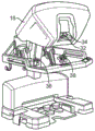
Fig. 1A is a top view of a robotic surgical system having an operating table with a plurality of robotic manipulators for robotically moving a surgical instrument having a surgical end effector at an internal surgical site within a patient, according to an embodiment of the present invention.
FIG. 1B graphically illustrates the robotic surgical system of FIG. 1A.
Fig. 2 is a perspective view illustrating a master surgeon console or workstation for inputting surgical procedure commands into the surgical system of fig. 1A, the console including a processor for generating manipulator command signals in response to the input commands.
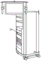
Fig. 3 is a perspective view of the electronics cart of fig. 1A.
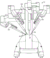
Fig. 4 is a perspective view of a patient side cart having four manipulator arms.
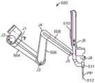
FIGS. 5A-5D show an example manipulator arm.
6A-6B show example manipulator arms in a front pitch configuration and a back pitch configuration, respectively.
Fig. 6C shows a graphical representation of the range of motion of the tip of an example manipulator arm surgical instrument tool, including a cone of rest (cone of rest) or cone-shaped tool entry restriction in each of the pitch and pitch configurations.
Fig. 7A shows an example manipulator arm having a proximal rotational joint that rotates the manipulator arm about an axis of the proximal rotational joint.
Fig. 7B shows an example manipulator arm having a proximal rotational joint that rotates the manipulator arm about an axis of the proximal rotational joint, and associated ranges of motion and cone dead space, the movement of the proximal rotational joint may be used to mitigate the depicted cone dead space.
Fig. 8 shows an example manipulator arm with a revolute joint near the distal instrument holder.
Fig. 9 shows an example manipulator arm with a rotational joint near the distal instrument holder that rotates or twists the instrument holder about the joint axis.
Fig. 10A-10C show sequential views of an example manipulator arm with a rotating joint near the distal instrument holder as the joint moves through its range of motion.
11A-11B show rotational cross-sectional views of an example manipulator arm with a distal rotational joint when the angular displacement of the joint is 0 and 90, respectively.
Fig. 12A-12D show an example manipulator arm having a proximal joint that translates the proximal joint supporting the manipulator arm about the path of the joint.
Fig. 13A-13C show an exemplary manipulator arm having proximal joints that translate the proximal joints supporting the manipulator arm about a path of the joints.
14A-14B graphically illustrate a relationship between an example manipulator assembly Jacobian null space and a null vertical space.
Fig. 14C graphically depicts the joint space of a "locked" joint relative to other joints.
15A-15B illustrate movement of the manipulator according to an example reconfiguration movement concurrent with an end effector displacing movement in which a proximal-most joint is locked out of the end effector displacing movement.
16A-16B are simplified block diagrams illustrating methods according to many embodiments.
Detailed Description
The present invention generally provides improved surgical and robotic devices, systems, and methods. The present invention is particularly advantageous for use with surgical robotic systems in which a plurality of surgical tools or instruments are mounted on and moved by an associated plurality of robotic manipulators during a surgical procedure. Robotic systems will typically include telerobotic, telesurgical, and/or telepresence systems that include a processor configured as a master-slave controller. By providing a robotic system that uses a processor suitably configured to move a manipulator assembly having an articulated linkage with a relatively large degree of freedom, the motion of the linkage may be adjusted to work through a minimally invasive access site. The large degree of freedom allows the system operator or an assistant to reconfigure the linkages of the manipulator assembly while maintaining the end effector state desired, optionally in preparation for surgery, and/or while other users manipulate the end effector during a surgical procedure.
The robotic manipulator assemblies described herein typically include a robotic manipulator and a tool mounted thereon (in surgical applications the tool typically comprises a surgical instrument), although the term "robotic assembly" also includes manipulators on which no tool is mounted. The term "tool" includes general or industrial robotic tools and specialized robotic surgical instruments, wherein these latter structures typically include end effectors adapted for tissue manipulation, tissue processing, tissue imaging, or the like. The tool/manipulator interface is typically a quick-disconnect tool holder or coupler, allowing the tool to be quickly removed and replaced with a replacement tool. The manipulator assembly typically has a base that is secured within an appropriate space during at least a portion of the robotic surgical procedure, and may include many degrees of freedom between the base and the end effector of the tool. Actuation of the end effector (e.g., opening or closing jaws of a clamping device, energizing an electrosurgical pedal (paddle), or the like) is generally independent of and external to these manipulator assembly degrees of freedom.
In various embodiments, the end effector moves within the workspace with between two and six degrees of freedom. As used herein, the term "orientation" includes both position and direction. Thus, a change in the position of an end effector (for example) may involve translation of the end effector from a first position to a second position, rotation of the end effector from a first orientation to a second orientation, or a combination of both. When used in minimally invasive robotic surgery, movement of the manipulator assembly may be controlled by a processor of the system such that the shaft or intermediate portion of the tool or instrument is constrained to move safely through a minimally invasive surgical access site or other aperture. Such movement may include, for example, axial insertion of the shaft into the surgical workspace through the aperture site, rotation of the shaft about its axis, and pivotal movement of the shaft about a pivot point adjacent the access site.
Many of the example manipulator assemblies described herein have degrees of freedom greater than that required to position and move an end effector within a surgical site. For example, a surgical end effector positionable at an internal surgical site through a minimally invasive aperture in six degrees of freedom may have nine degrees of freedom (six end effector degrees of freedom-three for position, three for orientation-plus three degrees of freedom to accommodate access site constraints) in some embodiments, but may have ten or more degrees of freedom. A highly configurable manipulator assembly having more degrees of freedom than are required for a given end effector position may be described as having or providing sufficient degrees of freedom to allow a range of joint states for end effector position within a workspace. For example, for a given end effector position, the manipulator assembly may occupy (and be driven between) any of a range of selectable manipulator linkage positions. Similarly, for a given end effector velocity vector, the manipulator assembly may have a range of different joint movement velocities for various joints of the manipulator assembly within the jacobian null-space.
The present invention provides a robotic linkage structure that is particularly well suited for surgical (and other) applications where a wide range of motion is desired, and for which limited dedicated volumes are available due to the presence of other robotic linkages, surgical personnel and equipment, and the like. The large range of motion and reduced bulk required for each robotic linkage may also provide greater flexibility between the location of the robotic support structure and the surgical or other work space, facilitating and expediting assembly.
The term "state" of a joint or the like generally refers herein to a control variable associated with the joint. For example, the state of an angular joint may refer to the angle that the joint defines within its range of motion, and/or to the angular velocity of the joint. Similarly, the state of an axial or translational (translational) joint may refer to the axial orientation of the joint, and/or to its axial velocity. Although many of the controllers described herein include velocity controllers, they also typically have some directional control characteristics. Alternative embodiments may rely primarily or entirely on position controllers, acceleration controllers, and the like. Many aspects of control systems that may be used with these devices are more fully described in U.S. patent No. 6,699,177, the entire disclosure of which is incorporated herein by reference. Thus, the calculations of joint movement and end effector movement described herein may be implemented using a position control algorithm, a velocity control algorithm, or a combination of both, and/or the like, so long as the movement is based on the associated calculations.
In various embodiments, the tool of the example manipulator arm pivots about a pivot point adjacent to the minimally invasive aperture. The system may utilize a hardware remote center, such as the remote center kinematics described in U.S. patent 6,786,896, the entire contents of which are incorporated herein in their entirety. These systems may also utilize a double parallelogram linkage that constrains the movement of the linkage such that the instrument shaft supported by the manipulator pivots about a remote center point. Alternative mechanically constrained remote center linkage systems are known and/or may be developed in the future. Unexpectedly, work in connection with the present invention has shown that remote center linkage systems benefit from highly configurable motion configurations. In particular, when the surgical robotic system has a linkage that allows pivotal motion about two axes intersecting at or near a minimally invasive surgical access site, the spherical pivotal motion may encompass the full range of motion desired within the patient, but may still suffer from avoidable deficiencies (e.g., being poorly constrained, being prone to arm-to-arm or arm-to-patient contact outside the patient, and/or the like). First, adding one or more additional degrees of freedom that are also mechanically constrained to pivotal movement at or near the access site appears to provide little or no increase in range of motion. Nonetheless, this joint may provide significant advantages by having the overall system configured or driven into a collision-preventing posture by further extending the range of motion of other surgical procedures, and the like. In other embodiments, the system may utilize software to implement a remote center, as described in U.S. patent application No. 8,004,229, the entire contents of which are incorporated herein by reference. In a system with a software remote center, the processor calculates the movement of the joint so as to pivot the middle portion of the instrument shaft about the calculated pivot point rather than the pivot point defined by the mechanical constraint. With the ability to calculate software pivot points, different modes characterized by system compliance or stiffness can be selectively implemented. More specifically, different system modes within a range of pivot points/centers (e.g., movable pivot points, passive pivot points, fixed/rigid pivot points, soft pivot points) may be implemented as desired.
Despite the many advantages of robotic surgical systems having multiple highly configurable manipulators, manual positioning of the links can be challenging and complex due to the large number of joints and links between the manipulator and the instrument. Even when balancing the manipulator structure to avoid gravitational effects, attempting to align each joint in a suitable arrangement or reconfigure the manipulator as desired may be difficult, time consuming, and may involve a great deal of training and/or skill. These challenges may be greater when the links of the manipulator are unbalanced around the joints, so that positioning such a highly configurable structure in a suitable configuration before or during surgery may be difficult due to the manipulator arm length and the passive and flexible design in many surgical systems.
These problems may be addressed by allowing a user, such as a physician's assistant, to quickly and easily reconfigure the manipulator arm, optionally even during end effector movement during a surgical procedure, while maintaining a desired end effector state. One or more additional joints may be included in the manipulator arm to increase the range of motion and configuration of the manipulator arm to enhance this performance. While providing additional joints may provide increased range of motion for certain tasks, the large number of redundant joints in a manipulator arm may cause various movements of the arm to be overly complex for other tasks, such that the movements may be unpredictable or the amount of overall movement causes various other clinical problems. It may further be useful to eliminate movement of one or more joints that are undesirable for a first task (referred to herein as "locking" joints or "locking joint sets") while allowing movement of the locking joint sets for various other tasks that may be performed simultaneously with the first task. Locking certain joints without actually physically constraining movement of the locked joints is advantageous because movement of the locked joints may be desirable to perform other tasks or movements. In various embodiments, the present invention further allows for the cancellation of the desired motion of one or more joints in a non-moving subset (or locked set) of joints, while still allowing the movement of the locked set of joints for various other movements, such as autonomous algorithm-based movements or commanded reconfiguration movements.
In certain aspects, commanded end effector movement within the surgical space is effected by driving one or more joints of the manipulator in accordance with coordinated end effector displacing movements of the joints calculated by the processor within the vertical null-space of the kinematic jacobian. Depending on the coordinated movements of the joints calculated within the null-space of the jacobian, various other tasks such as reconfiguration movements or auxiliary tasks such as collision avoidance movements may be performed by driving one or more joints of the manipulator while maintaining the desired end effector state, typically simultaneously with the end effector displacing movement.
In some embodiments, the calculated movements associated with various other tasks, such as avoidance movements based on autonomous algorithms, may override the cancellation movement so that the "locked joint" may still be moved to perform various other tasks. Examples of such Avoidance movements are described in U.S. provisional application No. 61/654,755 entitled "Manipula Arm-to-Patient precision estimation Using a Null-Space," filed on day 1, 2012 and U.S. provisional application No. 61/654,773 entitled "System and Methods for estimating similarities Using the Manipula Arm a Null-Space," filed on day 1, 2012, the disclosure of which is incorporated herein by reference in its entirety. However, the calculated movement covers the cancellation movement of the "locked" joint and is not limited to autonomous movement, and may include various other movements, such as commanded reconfiguration movements or various auxiliary movements.
Embodiments of the present invention may include a user input configured to take advantage of the degrees of freedom of the manipulator structure. Rather than manually reconfiguring the manipulator, the input facilitates use of the drive joints of the motion linkage to reconfigure the manipulator structure in response to an incoming reconfiguration command by the user. In various embodiments, user input for receiving reconfiguration commands is incorporated into and/or disposed proximate to the manipulator arm. In other embodiments, the input includes a centralized input device that facilitates reconfiguration of one or more joints, such as a set of buttons on a patient side cart or joystick. The input device for receiving reconfiguration commands may be separate from the input for receiving manipulation commands to effect movement of the end effector. The controller of the surgical system may include a processor having readable memory having recorded thereon joint controller programming instructions or code that allow the processor to drive the appropriate joint commands recorded thereon for driving the joints so as to allow the controller to implement the desired reconfiguration in response to entry of the reconfiguration command. However, it should be understood that the present invention may be used with manipulator arms with or without reconfiguration features.
In the following description, various embodiments of the present invention will be described. For purposes of explanation, specific configurations and details are set forth in order to provide a thorough understanding of the embodiments. However, it will also be apparent to one skilled in the art that the present invention may be practiced without the specific details. Furthermore, well-known features may be omitted or simplified in order not to obscure the described embodiments.
Referring now to the drawings, in which like reference numerals refer to like components throughout the several views, FIG. 1A is a top view example of a Minimally Invasive Robotic Surgery (MIRS) system 10 according to many embodiments, the system 10 being used to perform minimally invasive diagnostic or surgical procedures on a patient 12, the patient 12 lying on an operating table 14. The system may include a surgeon console 16 for use by a surgeon 18 during a surgical procedure. One or more assistants 20 may also participate in the process. The MIRS system 10 may further include a patient side cart 22 (surgical robot) and an electronics cart 24. The patient side cart 22 may manipulate at least one removably attachable tool assembly 26 (hereinafter referred to simply as a "tool") through a minimally invasive incision in the patient 12 while the surgeon 18 views the surgical site through the console 16. Images of the surgical site may be obtained through an endoscope 28, such as a stereo endoscope, and the endoscope 28 may be manipulated by the patient side cart 22 to orient the endoscope 28. The electronics cart 24 may be used to process images of the surgical site for subsequent display to the surgeon 18 through the surgeon console 16. The number of surgical tools 26 used at one time will generally depend on such factors as the diagnostic or surgical procedure and the space constraints within the operating room. If it is necessary to change one or more of the tools 26 used during the procedure, the assistant 20 may remove the tool 26 from the patient side cart 22 and replace it with another tool 26 from a tray 30 in the operating room.
FIG. 1B graphically illustrates a robotic surgical system 50 (e.g., the MIRS system 10 of FIG. 1A). As discussed above, a surgeon console 52 (such as surgeon console 16 in fig. 1A) may be used by a surgeon to control a patient side cart (surgical robot) 54 (such as patient side cart 22 in fig. 1A) during a minimally invasive procedure. The patient side cart 54 may capture images of the surgical procedure site using an imaging device, such as a stereoscopic endoscope, and output the captured images to an electronics cart 56 (such as electronics cart 24 in fig. 1A). As discussed above, the electronics cart 56 may process the captured image in a variety of ways prior to any subsequent display. For example, the electronics cart 56 may overlay the captured images with a virtual control interface prior to displaying the combined images to the surgeon via the surgeon console 52. The patient side cart 54 may output the captured images for processing outside of the electronics cart 56. For example, the patient side cart 54 may output the captured images to the processor 58, and the processor 58 may be used to process the captured images. The images may also be processed by a combination of the electronics cart 56 and the processor 58, and the electronics cart 56 and the processor 58 may be connected together to process the captured images collectively, sequentially, and/or in combinations thereof. One or more separate displays 60 may also be coupled to the processor 58 and/or the electronics cart 56 for locally and/or remotely displaying images, such as images of the surgical procedure site or other related images.
Fig. 2 is a perspective view of the surgeon's console 16. The surgeon console 16 includes a left eye display 32 and a right eye display 34 for presenting the surgeon 18 with coordinated (coordinated) stereoscopic views of the surgical site that achieve a sense of depth. The console 16 further includes one or more input controls 36, which in turn cause the patient side cart 22 (shown in fig. 1A) to maneuver one or more tools. The input control device 36 may provide the same degrees of freedom as its associated tool 26 (shown in fig. 1A) in order to provide the surgeon with a telepresence or feel that the input control device 36 is integral with the tool 26 so that the surgeon has a strong sense of directly controlling the tool 26. To this end, position, force and tactile feedback sensors (not shown) may be utilized to transmit position, force and tactile sensations from the tool 26 back to the surgeon's hand through the input control device 36.
The surgeon's console 16 is typically located in the same room as the patient so that the surgeon can directly monitor the procedure, participate in person if necessary, and speak directly to the assistant, rather than via telephone or other communication medium. However, the surgeon may be in a different room, a completely different building, or other remote location from the patient that allows for the telesurgical procedure.
Fig. 3 is a perspective view of the electronics cart 24. The electronics cart 24 may be connected to the endoscope 28 and may include a processor to process the captured images for subsequent display to the surgeon, such as on a surgeon console or other suitable display located locally and/or remotely. For example, where a stereoscopic endoscope is used, the electronics cart 24 may process the captured images in order to present a coordinated stereoscopic image of the surgical site to the surgeon. Such coordination may include correction between the opposing images and may include adjusting the stereoscopic working distance of the stereoscopic endoscope. As another example, image processing may include using previously determined camera calibration parameters to compensate for imaging errors of the image capture device, such as optical aberrations.
Fig. 4 shows a patient side cart 22 having a plurality of manipulator arms, each supporting a surgical instrument or tool 26 at a distal end of the manipulator arm. The illustrated plurality of patient side carts 22 includes four manipulator arms 100 that may be used to support a surgical tool 26 or an imaging device 28, such as a stereoscopic endoscope for capturing images of a surgical procedure site. The steering is provided by a robotic manipulator arm 100 having a number of robotic joints. The imaging device 28 and the surgical tool 26 may be positioned and manipulated through an incision in the patient such that the kinematic remote center remains at the incision in order to minimize the size of the incision. When the image of the surgical site is positioned within the field of view of the imaging device 28, it may include an image of the distal end of the surgical instrument or tool 26.
With respect to the surgical tool 26, a plurality of different types of selectable robotic surgical tools or instruments and different end effectors may be utilized, with at least some of the manipulator's instruments being removed and replaced during the surgical procedure. Several of these end effectors, including DeBakey forceps, micro-forceps, Potts scissors, and clip appliers, include first and second end effector elements that pivot relative to each other to define pairs of end effector jaws. Other end effectors, including scalpels and electrocautery probes, have a single end effector element. For instruments having end effector jaws, the jaws are typically actuated by squeezing a grasping member of the handle. For example, a single end effector instrument may also be actuated by grasping a grasping member to energize an electrocautery probe.
The elongate shaft of the instrument 26 allows the end effector and the distal end of the shaft to be inserted distally through a minimally invasive aperture into a surgical work site, typically through the abdominal wall or the like. The surgical work site may be insufflated, and movement of the end effector within the patient is typically effected at least in part by pivoting the instrument 26 about an axis through a minimally invasive aperture. In other words, manipulator 100 will move the proximal housing of the instrument outside of the patient such that the shaft extends through a minimally invasive aperture location in order to help provide the desired end effector movement. Thus, manipulator 100 typically undergoes significant movement outside of patient P during the surgical procedure.
An example manipulator arm in accordance with many embodiments of the present invention can be understood with reference to fig. 5A-13C. As noted above, the manipulator arm typically supports a proximal instrument or surgical tool and effects movement of the instrument relative to the base. As several different instruments with different end effectors may be sequentially mounted on each manipulator during a procedure (typically with the aid of a surgical assistant), the proximal instrument holder optionally allows for rapid removal and replacement of the mounted instrument or tool. As can be appreciated with reference to fig. 4, the manipulator is proximally mounted to the base of the patient side cart. In various embodiments, the manipulator arm includes a plurality of linkages and associated joints extending between the base and the proximal instrument holder. In certain aspects, an example manipulator includes a plurality of joints with redundant degrees of freedom such that the joints of the manipulator arm may be driven into a series of different configurations for a given end effector position. This is true for any embodiment of the manipulator arm disclosed herein.
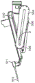
In certain embodiments as shown, for example, in fig. 5A, the exemplary manipulator arm includes a proximal revolute joint J1 that rotates about a first joint axis, such that the manipulator arm distal to the joint rotates about the joint axis. In some embodiments, rotary joint J1 is mounted directly to the base, while in other embodiments, joint J1 may be mounted to one or more movable linkages or joints. The combination of manipulator joints has redundant degrees of freedom such that the joints of the manipulator arm may be driven into a series of different configurations for a given end effector position. For example, the manipulator arms of fig. 5A-5D may be moved into different configurations while a distal component 511 (e.g., a tool 512 or a cannula through which an instrument shaft extends) supported within the instrument holder 510 remains in a particular state and may include a given end effector position or velocity. In various embodiments, distal part 511 is a cannula through which tool shaft 512 extends, while instrument holder 510 is a carriage (shown as a brick-like structure that translates over a round bar (spar)) to which an instrument is connected before extending through cannula 511 into a patient through a minimally invasive aperture.
Describing the joint rotation axes of the individual links of manipulator arm 500 of fig. 5A-5D and the connecting links illustrated in fig. 5A-5D, first link 504 extends distally from pivot joint J2, which pivots about its joint axis, and is connected to swivel joint J1, which rotates about its joint axis. As shown in fig. 5A, many of the remaining portions of the joint may be identified by their associated axes of rotation. For example, as shown, the distal end of the first link 504 is connected to the proximal end of the second link 506 at a pivot joint J3 that pivots about its pivot axis, while the proximal end of the third link 508 is connected to the distal end of the second link 506 at a pivot joint J4 that pivots about its axis. The distal end of the third link 508 is connected to the instrument holder 510 at pivot joint J5. In various embodiments, the pivot axes of each of joints J2, J3, J4, and J5 are substantially parallel, the linkages appear "stacked" when positioned immediately adjacent to each other, as shown in fig. 5D, to provide a reduced manipulator arm width w and increased patient clearance (clearance) during manipulation of the manipulator assembly. In various embodiments, the instrument holder further comprises additional joints, such as a translation joint J6, that facilitates axial movement of the instrument 512 through the minimally invasive aperture and connection of the instrument holder to a cannula through which the instrument is slidably inserted.
The distal member or cannula 511 through which the tool 512 extends may include additional degrees of freedom distal to the instrument holder 510. Actuation of the instrument degrees of freedom is typically driven by motors of the manipulator, and alternative embodiments may separate the instrument from the supporting manipulator structure at the quickly detachable instrument holder/instrument interface, such that one or more joints shown here as being on the instrument are instead on the interface, or vice versa. In some embodiments, cannula 511 includes a rotational joint (not shown) near or proximal to the tool tip insertion point or pivot point PP, which is typically disposed at a minimally invasive orifice site. The distal wrist joint of the instrument allows pivotal movement of the end effector of the surgical tool 512 about the instrument joint axis of one or more joints at the instrument wrist joint. The angle between the end effector jaw elements may be controlled independently of the end effector position and orientation.
The range of motion of the exemplary manipulator assembly may be understood by reference to fig. 6A-6C. During a surgical procedure, due to the need to access specific patient tissues within the surgical workspace, the exemplary manipulator arm may be manipulated into a front-pitch configuration as shown in fig. 6A or a back-pitch configuration as shown in fig. 6B. A typical manipulator assembly includes an end effector that can pitch forward and back at least ± 60 degrees about an axis, preferably about ± 75 degrees, and can also deviate from ± 80 degrees about the axis. While this aspect allows for increased maneuverability of the end effector with the assembly, configurations may also exist in which end effector movement may be limited, particularly when the manipulator arm is in a fully forward-pitched or fully back-pitched configuration as shown in fig. 6A and 6B. In one embodiment, the outer pitch and outer yaw joints of the manipulator arm have ranges of motion (ROM) of (+/-75 degrees) and (+/-300 degrees), respectively, and in some embodiments the ROM for the outer pitch can be increased to provide a ROM greater than (+/-90 degrees), in which case the "cone dead space" can be made to disappear completely, although the inner sphere normally associated with insertion limitations will remain. It is to be understood that various embodiments may be configured with increased or decreased ROM, the foregoing ROMs being provided for purposes of illustration, and that the invention is not otherwise limited to the ROMs described herein.
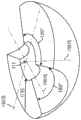
Fig. 6C graphically illustrates the overall range of motion and workspace of the exemplary manipulator tool tip of fig. 5A-5B. Although the workspace is shown as a hemisphere, it may also be represented as a sphere depending on the range of motion and configuration of one or more rotational joints of the manipulator, such as joint J1. As shown, the hemisphere in fig. 6C contains a central, small spherical cavity and two conical cavities. A cavity represents an area where tool tip movement may not be possible due to mechanical constraints or difficult to implement due to extremely high joint speeds that make movement of the end effector difficult or slow. For these reasons, the conical cavity is referred to as the "cone's dead space". In some embodiments, the manipulator arm may reach a pole (singularity) at a point within the cone. Since movement of the manipulator within or near the cone's dead space may be impaired, it may be difficult to move the manipulator arm away from the cone's dead space without manually moving one or more links of the manipulator to reconfigure the links and joints as desired, which often requires alternative modes of operation and delays the surgical procedure.
In various embodiments, movement of the instrument shaft into or near these conical portions typically occurs when the angle between the distal linkages within the manipulator is relatively small. This configuration can be avoided by reconfiguring the manipulator to increase the angle between the linkages (so that the linkages move into a more perpendicular orientation relative to each other). For example, in the configuration shown in fig. 6A and 6B, as the angle (angle a) between the distal-most link and the instrument holder becomes relatively small, movement of the manipulator may become more difficult. According to the range of joint movement among the remaining joints in various embodiments, as the angle between certain linkages is reduced, movement of the manipulator may be prevented and, in some cases, the manipulator arm may no longer be redundant. Manipulator configurations in which the instrument shaft is near these conical portions or in which the angle between the linkages is relatively low are referred to as "ill-conditioned," such that the maneuverability and dexterity of the manipulator arm is limited. It may be desirable for the manipulator to be "well-conditioned" in order to maintain dexterity and range of movement. In certain aspects, the present invention allows a user to avoid movement of the instrument shaft proximate the conical portion described above by simply entering a command to reconfigure the manipulator as desired, even during movement of the end effector during a surgical procedure. This is particularly useful if the manipulator becomes "ill-conditioned" for whatever reason.
While the embodiments of the manipulator described above may be used in the present invention, some embodiments may include additional joints, which may also be used to improve the dexterity and state of the manipulator arm. For example, an exemplary manipulator may include a revolute joint and/or linkage proximal to joint J1, which may be used to rotate the manipulator arm of fig. 5A, and its associated cone deadband, about the axis of the revolute joint, so as to reduce or eliminate the cone deadband. In another embodiment, the exemplary manipulator may further include a distal pivot joint that pivots the instrument holder about an axis substantially perpendicular to joint J5 to offset the tool tip to further reduce the cone dead space and increase the range of motion of the surgical tool. In another embodiment, a proximal joint of the manipulator arm, such as J1, may be movably mounted to the base to move or shift the cone deadband and improve the range of motion of the manipulator tool tip as desired. The use and advantages of these additional joints can be understood by reference to fig. 7A-13C, which illustrate examples of these joints that can be used independently of each other or in combination with each other in any of the exemplary manipulator arms described herein.
Fig. 7A-7B illustrate an additional redundant joint used with an exemplary manipulator arm, the first joint, connecting a proximal portion of the manipulator arm to the base. The first joint is a proximal rotary joint JtWhich makes the manipulator arm surround the joint JtThe joint axis of (a) is rotated. Proximal rotation JtInvolving the joint JtFrom proximal rotation JtLink 501 offset by a predetermined distance or angle. The link 501 may be a curved linkage as shown in fig. 7A, or a linear or angled linkage as shown in fig. 7B. As shown in the embodiment of FIG. 7A, joint JtMay be aligned with the remote center RC or insertion point of the tool tip. In various embodiments, joint J, as with each rotational joint axis of the manipulator armtPasses through the remote center to resist movement at the body wall and thus can be moved during surgery. Joint JtIs connected to the proximal portion of the arm so that it can be used to change the orientation and direction of the back of the arm. In general, redundant axes such as this allow the instrument tip to follow the surgeon's commands while avoiding collisions with other arms or patient anatomy. In some aspects of the present invention, the first and second electrodes are,proximal rotation JtOnly for changing the mounting angle of the manipulator relative to the ground. This angle is important in order to 1) avoid collisions with external patient anatomy and 2) reach anatomy within the patient. In various embodiments, the proximal revolute joint J is connected totThe angle a between the proximal link manipulator and the proximal rotation axis of (a) is about 15 degrees.
FIG. 7B illustrates proximal revolute joint J in an exemplary manipulator armtAnd the relationship between its associated joint axis and cone envelope. Proximal revolute joint JtMay pass through the cone envelope or may be completely outside the cone envelope. By rotating the manipulator arm about the proximal side JtThe cone dead space can be reduced (in the joint J)tThe axis passes through the cone's quiet space) or may be effectively eliminated (in embodiments where the proximal revolute joint axis extends completely outside the cone's quiet space). The distance and angle of link 501 determine joint JtThe orientation of the axis relative to the cone's dead space.
Fig. 8 illustrates another type of redundant joint used with an exemplary manipulator arm, which is a distal revolute joint J7 that connects the instrument holder 510 to the distal link of the manipulator arm 508. The distal revolute joint J7 allows the system to twist the instrument holder 510 about a joint axis that, in various embodiments, passes through a remote center or insertion point. Ideally, the revolute joint is located distally on the arm and is therefore particularly suited to moving the direction of the insertion axis. The addition of this redundant axis allows the manipulator to adopt multiple orientations for any single instrument tip orientation. In general, redundant axes such as this allow the instrument tip to follow the surgeon's commands while avoiding collisions with other arms or patient anatomy. Since the distal revolute joint J7 has the ability to move the insertion axis closer to the off-axis, it can increase the arm back pitch range of motion. The relationship between the axis of the distal revolute joint J7, the offset axis of J1, and the tool tip insertion axis is shown in fig. 9. Fig. 10A-10C show the sequential movement of J7 and how it shifts the insertion axis of the tool tip from side to side.
Another advantage of the distal revolute joint J7 is that it can reduce the patient clearance cone, which is the swept volume of the distal portion of the manipulator arm proximal to the insertion point that will space the patient apart to avoid collisions between the patient and the instrument holder or distal linkage of the manipulator arm. Fig. 11A illustrates the patient clearance cone of the proximal portion of the manipulator arm when the angular displacement of the distal rotary joint is maintained at 0 °. Fig. 11B illustrates a patient clearance cone reduced by the proximal portion of the manipulator arm when the distal revolute joint is shown having an angular displacement of 90 ° about its axis. Thus, during a surgical procedure with minimal patient clearance near the insertion point, the use of joint J7 according to the present invention may provide additional clearance while maintaining a remote center position or end effector orientation as desired.
Fig. 12A-13C illustrate another type of redundant joint used with an exemplary manipulator arm, a proximal joint, that translates or rotates the manipulator arm about an axis. In various embodiments, the proximal translatable joint articulates a proximal joint of the manipulator, such as joint J1 or JtThe translation along the path to reduce or eliminate the cone dead space by shifting or rotating the range of motion of the manipulator arm, thereby providing better condition and improved maneuverability of the manipulator arm. The translatable joint may comprise a circular path, such as joint J in FIGS. 12A-12DH1As shown, or may include a semi-circular or arcuate path, such as shown in fig. 13A-13C. Typically, the joint rotates the manipulator arm about an axis of the translatable joint that intersects the remote center RC about which the shaft of the tool 512 extending through the cannula 511 pivots. In the embodiment shown in FIGS. 12A-12D, JH1Is a vertical axis, and in the embodiment shown in fig. 13A-13C, JH2Is horizontal.
In certain embodiments, manipulator arm 500 may include a parallelogram configuration of any or all of the proximal or distal rotational joints, proximal translatable joints, and distal linkages. The use of any or all of these features provides additional redundant degrees of freedom and facilitates reconfiguration to provide a more "conditioned" manipulator assembly by increasing the angle between the linkages, thereby improving the dexterity and motion of the manipulator in accordance with the present invention. The increased flexibility of the exemplary manipulator may also be used to optimize the kinematics of the manipulator linkage in order to avoid joint limitations, extremes, and the like.
In some embodiments, joint movement of the manipulator is controlled by a controller driving one or more joints with motors of the system, the joints being driven according to coordinated joint movement calculated by a processor of the controller. Mathematically, the controller may perform calculations for at least some joint commands using vectors and/or matrices, some of which may have elements corresponding to joint configuration or velocity. The range of selectable joint configurations available to the processor may be conceptualized as joint space. The joint space may for example have as many dimensions as there are degrees of freedom of the manipulator, and a particular configuration of the manipulator may represent a particular point within the joint space, each coordinate corresponding to a joint state of the associated manipulator joint.
In an exemplary embodiment, the system includes a controller in which the commanded orientation and velocity of the components within a workspace, referred to herein as its Cartesian coordinate space (referred to herein as Cartesian space), are input. The component may be any component on or off the manipulator that can serve as a control frame that is articulated using control inputs. One example of a manipulator component used in many of the examples described herein is a tool tip. Another example of a part on the manipulator is a physical part that is not on the tool tip but is part of the manipulator, such as a pin or a painted pattern. One example of a component that is off the manipulator is a reference point in empty space that is precisely a distance and angle from the tool tip. Another example of a component that is disengaged from the manipulator is the target tissue, the orientation of which relative to the manipulator can be established. In all of these cases, the end effector is associated with an imaginary control frame that is to be articulated using the control inputs. However, hereinafter, "end effector" and "tool tip" are used synonymously. While there is typically no closed form relationship that maps a desired cartesian space end effector orientation to a corresponding joint space orientation, there is typically a closed form relationship between cartesian space end effector and joint space velocity. The kinematic jacobian is a matrix of partial derivatives of cartesian spatial orientation elements of the end effector relative to joint spatial orientation elements. In this manner, the kinematic jacobian captures the kinematic relationship between the end effector and the joint. In other words, the kinematic jacobian captures the effect of joint motion on the end effector. The kinematic jacobian (J) may be used to map joint-space velocity (dq/dt) to cartesian space end effector velocity (dx/dt) using the following relationship:
dx/dt=J dq/dt
thus, even when there is no closed form mapping between input and output orientations, the velocity mapping can be iteratively used in, for example, a jacobian-based controller to perform manipulator movements from commanded user inputs, although a variety of implementations are available. While many embodiments include a jacobian-based controller, some implementations may utilize a variety of controllers that may be configured to enter the jacobian of a manipulator arm to provide any of the features described herein.
One such implementation is described in the following simplified terms. The commanded joint orientation is used to calculate the jacobian (J). During each time step (Δ t), the Cartesian space velocity (dx/dt) is calculated to perform the desired movement (dx)Expectation ofDt) and the accumulated (build up) deviation (Δ x) from the desired cartesian spatial orientation. Then, pseudo-inverse of Jacobian (J) is used#) The Cartesian spatial velocities are converted to joint spatial velocities (dq/dt). The resulting joint space commanded velocity is then integrated to produce a joint space commanded orientation (q). These relationships are listed below:
dxdt=dxexpectation of/dt+KΔx (1)
dq/dt=J#dx/dt (2)
qi=qi-1+dq/dtΔt (3)
The pseudo-inverse of jacobian (J) directly maps the desired tool tip motion (and in some cases, the remote center of pivot tool motion) into the joint velocity space. A manipulator is said to be redundant if it is used that has more useful joint axes than the tool tip degrees of freedom (up to six), (and when the remote centre of tool motion is in use, the manipulator should have an additional three joint axes for the three degrees of freedom associated with the remote centre position). The jacobian of the redundant manipulator contains a "null space" having at least one dimension. In this case, the "null space" of the jacobian (n (j)) is the space of joint velocities that momentarily does not achieve tool tip motion (and pivot point position does not move when using a remote center); and "zero motion" is a combination, trajectory or course of joint orientations that also does not produce instantaneous movement of the tool tip and/or the remote center location. Incorporating or injecting the calculated null-space velocity into the control system of the manipulator to implement the desired reconfiguration of the manipulator (including any reconfiguration described herein) changes equation (2) above to the following:
dq/dt=dqis perpendicular to/dt+dqZero/dt (4)
dqIs perpendicular to/dt=J#dx/dt (5)
dq zero/dt ═ 1-J#J)z=VnVn Tz=Vnα (6)
The joint velocity according to equation (4) has two components: the first is a zero vertical spatial component, the "purest" joint velocity (shortest vector length) that produces the desired tool tip motion (and the desired remote center motion when using the remote center), and the second is a zero spatial component. Equations (2) and (5) show that the same equation is obtained without the null spatial component. Equation (6) starts on the left with the conventional form of the null-space component and on the far right shows the form used in the exemplary system, where (Vn) is the orthogonal basis vector set of null-space and (α) is the coefficient that blends these basis vectors. In some embodiments, α is determined by controlling a parameter, variable or setting, such as by using a knob or other control means, to shape or control motion within the null space as desired. Using equations (4) and (5) above, the following equations may be calculated to obtain a null-space coefficient that may be used to drive the joint to cancel the "lock" movement of the joint:
dq/dt=dqis perpendicular to/dt+Vnα (7)
The joint velocity in zero vertical space generated from the pseudo-inverse of the self-jacobian (see equations (4) and (5)) is opposed by the zero space velocity of the selected joint only for reaching the zero space dimension. If a "non-moving" or "locked" joint is considered, the component of the vector in equation (7) that is uniquely related becomes:
dqlocking in/dt=0=dqVertical (locking)/dt+Vn (Lock)α (8)
The relevant components of the locked joint (equation (8)) can then be solved according to a number of possible schemes to obtain the zero space coefficients needed to implement joint motion cancellation. One way is by calling p in the following equationContrary (.)The least norm least squares solution given by the pseudo-inverse of (a):
α=pinverse direction(Vn (Lock)dqVertical (locking)/dt (9)
An alternative approach is to use a weighted pseudo-inverse rather than an unweighted pseudo-inverse. This approach also provides for the desired cancellation of the motion of the joint, however in some cases there may be drawbacks associated with this approach. For example, it may mean that no null-space algorithm is used or in order to use the null-space basis vectors for other algorithms, both weighted and unweighted pseudo-inverses need to be computed in the same kernel iteration to remain valid. While there are various other ways to address these deficiencies, these methods may unnecessarily complicate the calculated movement to obtain the resulting movement allowed by the method outlined in the equation above.
Fig. 14A graphically illustrates a relationship between a null space of the jacobian and a null vertical space of the jacobian for an exemplary manipulator arm. FIG. 14A shows a two-dimensional schematic showing the view taken horizontallyNull space of axes (N (J)), and null vertical space along vertical axes (N)⊥(J) Two axes perpendicular to each other). Oblique vector Representing zero-space velocity vectors
 And zero perpendicular spatial velocity vector
 And the sum, which represents equation (4) above.
FIG. 14B graphically illustrates the relationship between null space and zero motion manifold within a four-dimensional joint space, shown as a "zero motion manifold". Each arrow (q1, q2, q3, and q4) represents a major joint axis. The closed curve represents a zero motion manifold, which is a set of joint space orientations that instantaneously achieve the same end effector orientation. For a given point a on the curve, the null-space is parallel to the zero-motion manifold tangent ρ + a at point a, since the null-space is the joint velocity space that does not instantaneously produce end effector movement.
Fig. 14C graphically illustrates the relationship between a "locked out" joint and the remaining joints in the joint space. The schematic shows that the multi-dimensional joint space is represented by a horizontal axis representing a "non-mobile" or "locked" joint (q) provided with motion cancellation, and a vertical axis and an internal/external axisi) The vertical axis and the inner/outer axis represent other joints (q) allowing movementj). Each axis may represent one or more joints. As noted above, motion cancellation may be applicable to certain types of movements, such as end effector displacing movements that effect commanded end effector manipulation, and the present schematic does not address movements of "non-moving" or "locked" joints that may be generated in response to various other types of movements, such as collision avoidance movements. In FIG. 14C, q [ k ]]Representing the current joint position in the multi-dimensional joint space. Oblique arrow pointing to upper left Is a zero-vertical vector that is the pseudo-inverse solution of the jacobian and lies within the zero-vertical space. The non-vertical vector extends to the center of the ellipse n (j), which represents the sum of the non-vertical vector and the set of all null-space vectors. Dotted vertical plane (q)i) Represents a hyperplane, which is a set of all joint configurations, locking the joint at the current q k]The value is obtained. Oblique arrow pointing to upper right
 Is a null space vector. Notably, the two oblique amounts are perpendicular to each other (the null-perpendicular-space is perpendicular to the null-space). As shown, when the sum of these two vectors (top to end) combined results in a joint orientation with no motion in the horizontal direction that represents joint movement. Thus, by combining the vectors as described above, the desired joint is effectively "locked in". Oblique line { qSolution (II)Denotes the intersection of the ellipse and the vertical hyperplane (the line extending in the three-dimensional joint space). Thus, { qSolution (II)Represents the set of all joint configurations that (i) are within non-perpendicular vectors and null-space movements and (ii) do not result in joint movements that are desired to be locked. Thus, { qSolution (II)The set of disarticulation configurations for which the desired joint is locked. Each of the ellipses shown in fig. 14C corresponds to a ellipse represented by
 Represented hyperplane in the joint space, here
 Is a vector in null space in joint velocity space. The two ellipses are composed of
 Separated and perpendicular thereto, and perpendicular to the hyperplane (q)i) Indicating the configuration of the joints when the locked joints are at their locked values. Point q [ k ]]Represents a time step [ k ]]And the resulting q is represented by q [ k +1 ]]It is represented by the time step [ k +1 ]]As represented by the equation shown in fig. 14C. In short, q[k+1]Is equal to q [ k ]]Plus joint movement, q [ k +1 ], associated with both null and null-perpendicular spaces]At a value called { qSolution (II)Within the solution space of.
Fig. 15A-15B schematically illustrate an example manipulator 500 before and after movement of the manipulator arm according to a reconfiguration movement that is concurrent with an end effector displacing movement in which the joint J is engagedtIs locked. In response to an end effector manipulation command entered by a user, the processor calculates a joint JtThe end effector of the joint of (a) is moved in a zero vertical space of the jacobian. The processor then calculates the cancellation movement of one or more joints in null-space such that the locked joint JtThe cancellation movement in the null space cancels the joint movement so that the joint at which the lock is cancelled is driven according to the calculated end effector shift movement and the joint at which the movement is cancelled (J)t) The movement is performed while the desired steering movement is being performed. Simultaneously with the end effector displacing movement, the manipulator arm is driven according to a reconfiguration movement calculated in response to a user command to reconfigure the manipulator arm. In determining the reconfiguration movement, the computing joint comprises a locked joint JtMovement within the jacobian null-space such that the reconfiguration movement provides a desired manipulator arm reconfiguration while maintaining end effector state. As shown in the example of FIGS. 15A-15B, the reconfiguration movement of the arm includes joint JtSo that even when the joint J is movedtLocked joints may move when performing movements related to another task, such as commanded reconfiguration of a manipulator arm, while locked out of end effector displacing movement.
In some embodiments, the system may be configured such that the velocity of the joint within the null-space is scaled according to the joint position and/or configuration, or any number of conditions. For example, a user may desire to drive the proximal-most joint design at a higher speed than the more distal joint in the manipulator arm during the reconfiguration movement. In addition, the system may be configured to maintain the orientation or state of any of the manipulator arm joints as desired.
In certain aspects, the system may receive reconfiguration commands from a system user in any number of ways. In some embodiments, the manipulator comprises an input device for receiving a reconfiguration command from a user. The input device may include one or more buttons or mechanisms for actuating one or more joints (or alternatively for moving one or more links) as desired. The input device may be provided on the Manipulator arm, typically at a location corresponding to a joint actuated in response to activation of the device, as described in U.S. provisional application No. 61/654,764 entitled "command Reconfiguration of a Surgical Manipulator Using the Null-Space," filed on 1/6/2012, the entire contents of which are incorporated herein for all purposes. Alternatively, the system may include an input device having a set of buttons or mechanisms, each corresponding to a joint or linkage of the manipulator arm. This embodiment allows the user to reconfigure the arm from a centralized location. Alternatively, the input device may comprise a joystick operable to drive one or more joints and effect reconfiguration as desired. It should be understood that the input device may include any number of variations.
Fig. 16A-16B illustrate a method of reconfiguring a robotic surgical system manipulator assembly according to many embodiments of the present invention. Fig. 16A shows a simplified diagram of the necessary modules required to execute a conventional algorithm to control the patient side cart articulation status, which is related to the equations discussed above. According to the method of FIG. 16A, the system: calculating the positive motion of the manipulator arm; then dx/dt is calculated using equation (1) and dq is calculated using equation (5)Is perpendicular toDt, then calculated using equation (6) can depend on dqIs perpendicular toDq from z of/dt and jacobianZeroAnd/dt. Then, from the calculated dqIs perpendicular toDt and dqZeroAnd/dt, the system calculates dq/dt and q using equations (4) and (3), respectively, to provide movement, whereby the controller can implement the desired manipulator reconfiguration while maintaining the desired end effector state (and/or remote center position).
FIG. 16B shows a block diagram of an example implementation of a system. Sound boxIn response to a steering command commanding a desired tool tip state, a processor of the system determines a tool tip velocity and a joint state from which dq is calculatedIs perpendicular toAnd/dt. If any joint is designated as "non-moving" or "locked," the system calculates dq for the designated jointIs perpendicular toDt such that when combined dqIs perpendicular toDt component and dqZeroThe/dt component causes the locked joint to not move. Optionally, the user may change the reconfiguration command to reconfigure the manipulator arm, if desired. In response to receiving a reconfiguration command from the user, the processor may utilize the determined tool tip and joint velocity (or calculated dq)Is perpendicular toDt) to calculate dqZeroAfter which the system adds the velocity for all joints to the calculated dq/dt in order to drive the joint(s) of the system and implement the desired end effector movement (or state) in which movement of the "non-moving" or "locked" joints is cancelled and reconfiguration of the manipulator arm, which may include movement of the locked joints.
Although the example embodiments have been described in some detail for purposes of clarity of understanding and by way of example, various modifications, improvements and changes will be apparent to those skilled in the art. Accordingly, the scope of the invention is to be limited only by the following claims.
Claims (4)
1. A system for cancelling joint motion, the system comprising:
a manipulator arm, the manipulator arm comprising: a proximal portion connected to a base, including a distal portion of an end effector, and a plurality of joints between the distal portion and the base, the plurality of joints providing sufficient degrees of freedom to allow a range of different states of the plurality of joints for a given state of the distal portion; and
an input device; and
a processor having a controller, the processor coupled to the manipulator arm and the input device, the processor configured to perform operations comprising:
receiving a command from the input device to move the end effector of the manipulator arm in an end effector shift;
designating one or more non-moving joints of the plurality of joints;
determining end effector displacing movement of the plurality of joints to effect the end effector displacing by calculating joint velocities within a zero vertical space of a Jacobian for the plurality of joints;
determining a cancellation movement of the plurality of joints by calculating joint velocities of the plurality of joints within a null-space of the Jacobian, the null-space being orthogonal to the null-perpendicular space, and the cancellation movement providing joint movement cancellation of each of the one or more non-moving joints when the cancellation movement is combined with the end effector displacing movement; and is
Driving the plurality of joints to effect the end effector displacement by combining the end effector displacing movement and the cancelling movement.
2. The system of claim 1, wherein the processor is further configured to perform operations comprising:
determining an auxiliary movement of a first joint set of the plurality of joints, the first joint set selected from the one or more non-moving joints of the plurality of joints, and the auxiliary movement determined within the null-space; and is
Driving the plurality of joints by combining the auxiliary movement with the end effector displacing movement and the cancelling movement to achieve a target of the auxiliary movement, the target of the auxiliary movement including a desired pose, a desired configuration, or collision avoidance of the manipulator arm.
3. A memory device comprising instructions that, when executed by one or more processors with a controller, cause the one or more processors to perform operations comprising:
receiving a command from an input device to move an end effector of a manipulator arm in an end effector shift, the manipulator arm comprising: a proximal portion connected to a base, including a distal portion of the end effector, and a plurality of joints between the distal portion and the base, the plurality of joints providing sufficient degrees of freedom to allow a range of different states of the plurality of joints for a given state of the distal portion;
designating one or more non-moving joints of the plurality of joints;
determining the end effector displacing movement of the plurality of joints to achieve the end effector displacing movement by calculating joint velocities of end effector displacing movement within a zero vertical space of a Jacobian for the plurality of joints;
determining a cancellation movement of the plurality of joints by calculating joint velocities for the cancellation movement of the plurality of joints within a null-space of the Jacobian, the null-space being orthogonal to the null-perpendicular space, and the cancellation movement providing joint movement cancellation for each of the one or more non-moving joints when the cancellation movement is combined with the end effector displacing movement; and is
Driving the plurality of joints to effect the end effector displacement by combining the end effector displacing movement and the cancelling movement.
4. The memory device of claim 3, wherein the memory device further comprises instructions that, when executed by the one or more processors, cause the one or more processors to perform operations comprising:
determining an auxiliary movement of a first joint set of the plurality of joints, the first joint set selected from the one or more non-moving joints of the plurality of joints, and the auxiliary movement being within the null-space; and is
Driving the plurality of joints by combining the auxiliary movement with the end effector displacing movement and the cancelling movement to achieve a target of the auxiliary movement, the target of the auxiliary movement including a desired pose, a desired configuration, or collision avoidance of the manipulator arm.
Applications Claiming Priority (3)
| Application Number | Priority Date | Filing Date | Title |
|---|---|---|---|
| US201261683638P | 2012-08-15 | 2012-08-15 | |
| US61/683,638 | 2012-08-15 | ||
| CN201380053744.3A CN104717935B (en) | 2012-08-15 | 2013-08-15 | Cancel the system of joint motions using kernel |
Related Parent Applications (1)
| Application Number | Title | Priority Date | Filing Date |
|---|---|---|---|
| CN201380053744.3A Division CN104717935B (en) | 2012-08-15 | 2013-08-15 | Cancel the system of joint motions using kernel |
Publications (2)
| Publication Number | Publication Date |
|---|---|
| CN108524001A CN108524001A (en) | 2018-09-14 |
| CN108524001B true CN108524001B (en) | 2021-06-29 |
Family
ID=50100577
Family Applications (2)
| Application Number | Title | Priority Date | Filing Date |
|---|---|---|---|
| CN201380053744.3A Active CN104717935B (en) | 2012-08-15 | 2013-08-15 | Cancel the system of joint motions using kernel |
| CN201810171182.7A Active CN108524001B (en) | 2012-08-15 | 2013-08-15 | System for cancelling joint motion by utilizing null space |
Family Applications Before (1)
| Application Number | Title | Priority Date | Filing Date |
|---|---|---|---|
| CN201380053744.3A Active CN104717935B (en) | 2012-08-15 | 2013-08-15 | Cancel the system of joint motions using kernel |
Country Status (6)
| Country | Link |
|---|---|
| US (2) | US9107683B2 (en) |
| EP (1) | EP2884937B1 (en) |
| JP (2) | JP6220877B2 (en) |
| KR (1) | KR102109594B1 (en) |
| CN (2) | CN104717935B (en) |
| WO (1) | WO2014028703A1 (en) |
Families Citing this family (155)
| Publication number | Priority date | Publication date | Assignee | Title |
|---|---|---|---|---|
| US9415510B2 (en) | 1999-09-17 | 2016-08-16 | Intuitive Surgical Operations, Inc. | System and methods for positioning a manipulator arm by clutching within a null-perpendicular space concurrent with null-space movement |
| US10653497B2 (en) | 2006-02-16 | 2020-05-19 | Globus Medical, Inc. | Surgical tool systems and methods |
| US10893912B2 (en) | 2006-02-16 | 2021-01-19 | Globus Medical Inc. | Surgical tool systems and methods |
| US10357184B2 (en) | 2012-06-21 | 2019-07-23 | Globus Medical, Inc. | Surgical tool systems and method |
| US9119655B2 (en) | 2012-08-03 | 2015-09-01 | Stryker Corporation | Surgical manipulator capable of controlling a surgical instrument in multiple modes |
| WO2012131660A1 (en) | 2011-04-01 | 2012-10-04 | Ecole Polytechnique Federale De Lausanne (Epfl) | Robotic system for spinal and other surgeries |
| KR102222959B1 (en) | 2012-06-01 | 2021-03-05 | 인튜어티브 서지컬 오퍼레이션즈 인코포레이티드 | Surgical instrument manipulator aspects |
| WO2013181507A1 (en) * | 2012-06-01 | 2013-12-05 | Intuitive Surgical Operations, Inc. | Systems and methods for commanded reconfiguration of a surgical manipulator using the null-space |
| US11864839B2 (en) | 2012-06-21 | 2024-01-09 | Globus Medical Inc. | Methods of adjusting a virtual implant and related surgical navigation systems |
| US10136954B2 (en) | 2012-06-21 | 2018-11-27 | Globus Medical, Inc. | Surgical tool systems and method |
| US11395706B2 (en) | 2012-06-21 | 2022-07-26 | Globus Medical Inc. | Surgical robot platform |
| US11793570B2 (en) | 2012-06-21 | 2023-10-24 | Globus Medical Inc. | Surgical robotic automation with tracking markers |
| US11253327B2 (en) | 2012-06-21 | 2022-02-22 | Globus Medical, Inc. | Systems and methods for automatically changing an end-effector on a surgical robot |
| US10624710B2 (en) | 2012-06-21 | 2020-04-21 | Globus Medical, Inc. | System and method for measuring depth of instrumentation |
| US11399900B2 (en) | 2012-06-21 | 2022-08-02 | Globus Medical, Inc. | Robotic systems providing co-registration using natural fiducials and related methods |
| US10646280B2 (en) | 2012-06-21 | 2020-05-12 | Globus Medical, Inc. | System and method for surgical tool insertion using multiaxis force and moment feedback |
| US10231791B2 (en) | 2012-06-21 | 2019-03-19 | Globus Medical, Inc. | Infrared signal based position recognition system for use with a robot-assisted surgery |
| US11857266B2 (en) | 2012-06-21 | 2024-01-02 | Globus Medical, Inc. | System for a surveillance marker in robotic-assisted surgery |
| US11607149B2 (en) | 2012-06-21 | 2023-03-21 | Globus Medical Inc. | Surgical tool systems and method |
| US11896446B2 (en) | 2012-06-21 | 2024-02-13 | Globus Medical, Inc | Surgical robotic automation with tracking markers |
| US10758315B2 (en) | 2012-06-21 | 2020-09-01 | Globus Medical Inc. | Method and system for improving 2D-3D registration convergence |
| US11786324B2 (en) | 2012-06-21 | 2023-10-17 | Globus Medical, Inc. | Surgical robotic automation with tracking markers |
| US10874466B2 (en) | 2012-06-21 | 2020-12-29 | Globus Medical, Inc. | System and method for surgical tool insertion using multiaxis force and moment feedback |
| US11317971B2 (en) | 2012-06-21 | 2022-05-03 | Globus Medical, Inc. | Systems and methods related to robotic guidance in surgery |
| US10799298B2 (en) | 2012-06-21 | 2020-10-13 | Globus Medical Inc. | Robotic fluoroscopic navigation |
| US10350013B2 (en) | 2012-06-21 | 2019-07-16 | Globus Medical, Inc. | Surgical tool systems and methods |
| US11298196B2 (en) | 2012-06-21 | 2022-04-12 | Globus Medical Inc. | Surgical robotic automation with tracking markers and controlled tool advancement |
| US11589771B2 (en) | 2012-06-21 | 2023-02-28 | Globus Medical Inc. | Method for recording probe movement and determining an extent of matter removed |
| US11116576B2 (en) | 2012-06-21 | 2021-09-14 | Globus Medical Inc. | Dynamic reference arrays and methods of use |
| US11864745B2 (en) | 2012-06-21 | 2024-01-09 | Globus Medical, Inc. | Surgical robotic system with retractor |
| US10842461B2 (en) | 2012-06-21 | 2020-11-24 | Globus Medical, Inc. | Systems and methods of checking registrations for surgical systems |
| US11045267B2 (en) | 2012-06-21 | 2021-06-29 | Globus Medical, Inc. | Surgical robotic automation with tracking markers |
| JP2015528713A (en) | 2012-06-21 | 2015-10-01 | グローバス メディカル インコーポレイティッド | Surgical robot platform |
| US11857149B2 (en) | 2012-06-21 | 2024-01-02 | Globus Medical, Inc. | Surgical robotic systems with target trajectory deviation monitoring and related methods |
| US9226796B2 (en) | 2012-08-03 | 2016-01-05 | Stryker Corporation | Method for detecting a disturbance as an energy applicator of a surgical instrument traverses a cutting path |
| CN104736092B (en) | 2012-08-03 | 2017-07-21 | 史赛克公司 | Systems and methods for robotic surgery |
| WO2014028703A1 (en) * | 2012-08-15 | 2014-02-20 | Intuitive Surgical Operations, Inc. | Systems and methods for cancellation of joint motion using the null-space |
| EP2969404B1 (en) * | 2013-03-15 | 2021-08-11 | Intuitive Surgical Operations, Inc. | Systems for using the null space to emphasize anipulator joint motion anisotropically |
| CA2905968A1 (en) | 2013-03-15 | 2014-09-25 | Sri International | Hyperdexterous surgical system |
| CN105050526B (en) | 2013-03-15 | 2018-06-01 | 直观外科手术操作公司 | Using kernel with the system and method at the convenient edge into cartesian coordinate space |
| US9283048B2 (en) | 2013-10-04 | 2016-03-15 | KB Medical SA | Apparatus and systems for precise guidance of surgical tools |
| EP3094272B1 (en) | 2014-01-15 | 2021-04-21 | KB Medical SA | Notched apparatus for guidance of an insertable instrument along an axis during spinal surgery |
| WO2015121311A1 (en) | 2014-02-11 | 2015-08-20 | KB Medical SA | Sterile handle for controlling a robotic surgical system from a sterile field |
| EP3120979A4 (en) * | 2014-03-14 | 2017-11-08 | Sony Corporation | Robot arm device, robot arm control method and program |
| EP3119333B1 (en) * | 2014-03-17 | 2021-05-05 | Intuitive Surgical Operations, Inc. | System for aligning with a reference target |
| EP3119319B1 (en) * | 2014-03-17 | 2020-07-15 | Intuitive Surgical Operations, Inc. | Tele-operative surgical systems and methods of control at joint limits using inverse kinematics |
| EP3134022B1 (en) | 2014-04-24 | 2018-01-10 | KB Medical SA | Surgical instrument holder for use with a robotic surgical system |
| US10828120B2 (en) | 2014-06-19 | 2020-11-10 | Kb Medical, Sa | Systems and methods for performing minimally invasive surgery |
| WO2016008880A1 (en) | 2014-07-14 | 2016-01-21 | KB Medical SA | Anti-skid surgical instrument for use in preparing holes in bone tissue |
| US10765438B2 (en) | 2014-07-14 | 2020-09-08 | KB Medical SA | Anti-skid surgical instrument for use in preparing holes in bone tissue |
| CN107072728B (en) | 2014-10-27 | 2020-07-17 | 直观外科手术操作公司 | System and method for monitoring control points during reactive motion |
| KR102617042B1 (en) | 2014-10-27 | 2023-12-27 | 인튜어티브 서지컬 오퍼레이션즈 인코포레이티드 | System and method for registering to a surgical table |
| CN110584789B (en) | 2014-10-27 | 2022-09-20 | 直观外科手术操作公司 | System and method for instrument interference compensation |
| US10624807B2 (en) | 2014-10-27 | 2020-04-21 | Intuitive Surgical Operations, Inc. | System and method for integrated surgical table icons |
| US10405944B2 (en) | 2014-10-27 | 2019-09-10 | Intuitive Surgical Operations, Inc. | Medical device with active brake release control |
| JP6676061B2 (en) * | 2014-10-27 | 2020-04-08 | インテュイティブ サージカル オペレーションズ, インコーポレイテッド | System and method for integrated operating table motion |
| EP3212149A4 (en) | 2014-10-27 | 2018-05-30 | Intuitive Surgical Operations, Inc. | System and method for integrated surgical table |
| US11103316B2 (en) | 2014-12-02 | 2021-08-31 | Globus Medical Inc. | Robot assisted volume removal during surgery |
| US10013808B2 (en) | 2015-02-03 | 2018-07-03 | Globus Medical, Inc. | Surgeon head-mounted display apparatuses |
| WO2016131903A1 (en) | 2015-02-18 | 2016-08-25 | KB Medical SA | Systems and methods for performing minimally invasive spinal surgery with a robotic surgical system using a percutaneous technique |
| EP3294184B1 (en) | 2015-05-11 | 2023-07-12 | Covidien LP | Coupling instrument drive unit and robotic surgical instrument |
| WO2016205452A1 (en) | 2015-06-19 | 2016-12-22 | Covidien Lp | Controlling robotic surgical instruments with bidirectional coupling |
| US10646298B2 (en) | 2015-07-31 | 2020-05-12 | Globus Medical, Inc. | Robot arm and methods of use |
| US10058394B2 (en) | 2015-07-31 | 2018-08-28 | Globus Medical, Inc. | Robot arm and methods of use |
| US10080615B2 (en) | 2015-08-12 | 2018-09-25 | Globus Medical, Inc. | Devices and methods for temporary mounting of parts to bone |
| EP3344179B1 (en) | 2015-08-31 | 2021-06-30 | KB Medical SA | Robotic surgical systems |
| WO2017041159A1 (en) * | 2015-09-11 | 2017-03-16 | Synaptive Medical (Barbados) Inc. | End effector joystick for a positioning device |
| US10034716B2 (en) | 2015-09-14 | 2018-07-31 | Globus Medical, Inc. | Surgical robotic systems and methods thereof |
| US9771092B2 (en) | 2015-10-13 | 2017-09-26 | Globus Medical, Inc. | Stabilizer wheel assembly and methods of use |
| JP6157786B1 (en) * | 2016-01-22 | 2017-07-05 | オリンパス株式会社 | Medical manipulator system |
| US10448910B2 (en) | 2016-02-03 | 2019-10-22 | Globus Medical, Inc. | Portable medical imaging system |
| US10117632B2 (en) | 2016-02-03 | 2018-11-06 | Globus Medical, Inc. | Portable medical imaging system with beam scanning collimator |
| US11883217B2 (en) | 2016-02-03 | 2024-01-30 | Globus Medical, Inc. | Portable medical imaging system and method |
| US10842453B2 (en) | 2016-02-03 | 2020-11-24 | Globus Medical, Inc. | Portable medical imaging system |
| US11058378B2 (en) | 2016-02-03 | 2021-07-13 | Globus Medical, Inc. | Portable medical imaging system |
| WO2017146890A1 (en) | 2016-02-26 | 2017-08-31 | Intuitive Surgical Operations, Inc. | System and method for collision avoidance using virtual boundaries |
| US10866119B2 (en) | 2016-03-14 | 2020-12-15 | Globus Medical, Inc. | Metal detector for detecting insertion of a surgical device into a hollow tube |
| JP7022709B2 (en) | 2016-07-01 | 2022-02-18 | インテュイティブ サージカル オペレーションズ, インコーポレイテッド | Computer-aided medical system and method |
| US10111719B2 (en) * | 2016-08-16 | 2018-10-30 | Ethicon Llc | Control of the rate of actuation of tool mechanism based on inherent parameters |
| US10647007B2 (en) | 2016-09-16 | 2020-05-12 | Verb Surgical Inc. | Capacitor sensor including two plates having both conductive and non conductive regions |
| EP3513095B1 (en) | 2016-09-16 | 2021-10-20 | Verb Surgical Inc. | Belt termination and tensioning in a pulley arrangement for a robotic arm |
| KR102257827B1 (en) * | 2016-09-16 | 2021-05-31 | 버브 서지컬 인크. | Robot arm |
| US11039893B2 (en) | 2016-10-21 | 2021-06-22 | Globus Medical, Inc. | Robotic surgical systems |
| US11173003B2 (en) | 2017-01-10 | 2021-11-16 | Intuitive Surgical Operations, Inc. | Systems and methods for using a robotic medical system |
| JP2018114280A (en) | 2017-01-18 | 2018-07-26 | ケービー メディカル エスアー | Universal instrument guide for robotic surgical system, surgical instrument system, and method of using them |
| EP3351202B1 (en) | 2017-01-18 | 2021-09-08 | KB Medical SA | Universal instrument guide for robotic surgical systems |
| JP7233841B2 (en) | 2017-01-18 | 2023-03-07 | ケービー メディカル エスアー | Robotic Navigation for Robotic Surgical Systems |
| US11071594B2 (en) | 2017-03-16 | 2021-07-27 | KB Medical SA | Robotic navigation of robotic surgical systems |
| GB2562291B (en) * | 2017-05-11 | 2023-02-01 | Freehand 2010 Ltd | A tool holder and system |
| WO2018216204A1 (en) * | 2017-05-26 | 2018-11-29 | オリンパス株式会社 | Master-slave manipulator and method for controlling same |
| US10675094B2 (en) | 2017-07-21 | 2020-06-09 | Globus Medical Inc. | Robot surgical platform |
| JP7013766B2 (en) * | 2017-09-22 | 2022-02-01 | セイコーエプソン株式会社 | Robot control device, robot system, and control method |
| CN107510507A (en) * | 2017-09-26 | 2017-12-26 | 广西南宁栩兮科技有限公司 | A kind of surgical Aided Machine arm |
| CN107811710B (en) * | 2017-10-31 | 2019-09-17 | 微创(上海)医疗机器人有限公司 | Operation aided positioning system |
| US11612306B2 (en) * | 2017-11-01 | 2023-03-28 | Sony Corporation | Surgical arm system and surgical arm control system |
| US11382666B2 (en) | 2017-11-09 | 2022-07-12 | Globus Medical Inc. | Methods providing bend plans for surgical rods and related controllers and computer program products |
| US11794338B2 (en) | 2017-11-09 | 2023-10-24 | Globus Medical Inc. | Robotic rod benders and related mechanical and motor housings |
| US10898252B2 (en) | 2017-11-09 | 2021-01-26 | Globus Medical, Inc. | Surgical robotic systems for bending surgical rods, and related methods and devices |
| US11134862B2 (en) | 2017-11-10 | 2021-10-05 | Globus Medical, Inc. | Methods of selecting surgical implants and related devices |
| US10919149B2 (en) * | 2017-11-24 | 2021-02-16 | Denso Wave Incorporated | Controller for robot and inverse transforming method for robot |
| US11154369B2 (en) | 2018-01-24 | 2021-10-26 | Think Surgical, Inc. | Environmental mapping for robotic assisted surgery |
| US20190254753A1 (en) | 2018-02-19 | 2019-08-22 | Globus Medical, Inc. | Augmented reality navigation systems for use with robotic surgical systems and methods of their use |
| US10573023B2 (en) | 2018-04-09 | 2020-02-25 | Globus Medical, Inc. | Predictive visualization of medical imaging scanner component movement |
| US11337742B2 (en) | 2018-11-05 | 2022-05-24 | Globus Medical Inc | Compliant orthopedic driver |
| US11278360B2 (en) | 2018-11-16 | 2022-03-22 | Globus Medical, Inc. | End-effectors for surgical robotic systems having sealed optical components |
| US11744655B2 (en) | 2018-12-04 | 2023-09-05 | Globus Medical, Inc. | Drill guide fixtures, cranial insertion fixtures, and related methods and robotic systems |
| US11602402B2 (en) | 2018-12-04 | 2023-03-14 | Globus Medical, Inc. | Drill guide fixtures, cranial insertion fixtures, and related methods and robotic systems |
| WO2020172394A1 (en) | 2019-02-22 | 2020-08-27 | Auris Health, Inc. | Surgical platform with motorized arms for adjustable arm supports |
| US11918313B2 (en) | 2019-03-15 | 2024-03-05 | Globus Medical Inc. | Active end effectors for surgical robots |
| US11571265B2 (en) | 2019-03-22 | 2023-02-07 | Globus Medical Inc. | System for neuronavigation registration and robotic trajectory guidance, robotic surgery, and related methods and devices |
| US20200297357A1 (en) | 2019-03-22 | 2020-09-24 | Globus Medical, Inc. | System for neuronavigation registration and robotic trajectory guidance, robotic surgery, and related methods and devices |
| US11806084B2 (en) | 2019-03-22 | 2023-11-07 | Globus Medical, Inc. | System for neuronavigation registration and robotic trajectory guidance, and related methods and devices |
| US11317978B2 (en) | 2019-03-22 | 2022-05-03 | Globus Medical, Inc. | System for neuronavigation registration and robotic trajectory guidance, robotic surgery, and related methods and devices |
| US11382549B2 (en) | 2019-03-22 | 2022-07-12 | Globus Medical, Inc. | System for neuronavigation registration and robotic trajectory guidance, and related methods and devices |
| US11419616B2 (en) | 2019-03-22 | 2022-08-23 | Globus Medical, Inc. | System for neuronavigation registration and robotic trajectory guidance, robotic surgery, and related methods and devices |
| US11045179B2 (en) | 2019-05-20 | 2021-06-29 | Global Medical Inc | Robot-mounted retractor system |
| US11628023B2 (en) | 2019-07-10 | 2023-04-18 | Globus Medical, Inc. | Robotic navigational system for interbody implants |
| US11235459B2 (en) * | 2019-08-15 | 2022-02-01 | Intrinsic Innovation Llc | Inverse kinematic solver for wrist offset robots |
| US11571171B2 (en) | 2019-09-24 | 2023-02-07 | Globus Medical, Inc. | Compound curve cable chain |
| US11426178B2 (en) | 2019-09-27 | 2022-08-30 | Globus Medical Inc. | Systems and methods for navigating a pin guide driver |
| US11890066B2 (en) | 2019-09-30 | 2024-02-06 | Globus Medical, Inc | Surgical robot with passive end effector |
| US11864857B2 (en) | 2019-09-27 | 2024-01-09 | Globus Medical, Inc. | Surgical robot with passive end effector |
| US11510684B2 (en) | 2019-10-14 | 2022-11-29 | Globus Medical, Inc. | Rotary motion passive end effector for surgical robots in orthopedic surgeries |
| RU2753118C2 (en) * | 2020-01-09 | 2021-08-11 | Федеральное государственное автономное образовательное учреждение высшего образования "Севастопольский государственный университет" | Robotic system for holding and moving surgical instrument during laparoscopic operations |
| US11464581B2 (en) | 2020-01-28 | 2022-10-11 | Globus Medical, Inc. | Pose measurement chaining for extended reality surgical navigation in visible and near infrared spectrums |
| US11382699B2 (en) | 2020-02-10 | 2022-07-12 | Globus Medical Inc. | Extended reality visualization of optical tool tracking volume for computer assisted navigation in surgery |
| US11207150B2 (en) | 2020-02-19 | 2021-12-28 | Globus Medical, Inc. | Displaying a virtual model of a planned instrument attachment to ensure correct selection of physical instrument attachment |
| GB2592378B (en) * | 2020-02-25 | 2024-04-03 | Cmr Surgical Ltd | Controlling movement of a surgical robot arm |
| US11253216B2 (en) | 2020-04-28 | 2022-02-22 | Globus Medical Inc. | Fixtures for fluoroscopic imaging systems and related navigation systems and methods |
| US11510750B2 (en) | 2020-05-08 | 2022-11-29 | Globus Medical, Inc. | Leveraging two-dimensional digital imaging and communication in medicine imagery in three-dimensional extended reality applications |
| US11153555B1 (en) | 2020-05-08 | 2021-10-19 | Globus Medical Inc. | Extended reality headset camera system for computer assisted navigation in surgery |
| US11382700B2 (en) | 2020-05-08 | 2022-07-12 | Globus Medical Inc. | Extended reality headset tool tracking and control |
| US11317973B2 (en) | 2020-06-09 | 2022-05-03 | Globus Medical, Inc. | Camera tracking bar for computer assisted navigation during surgery |
| US11382713B2 (en) | 2020-06-16 | 2022-07-12 | Globus Medical, Inc. | Navigated surgical system with eye to XR headset display calibration |
| CN113855243B (en) * | 2020-06-30 | 2024-01-23 | 北京术锐机器人股份有限公司 | Telecentric motion mechanism and surgical robot system |
| US11877807B2 (en) | 2020-07-10 | 2024-01-23 | Globus Medical, Inc | Instruments for navigated orthopedic surgeries |
| US11793588B2 (en) | 2020-07-23 | 2023-10-24 | Globus Medical, Inc. | Sterile draping of robotic arms |
| US11737831B2 (en) | 2020-09-02 | 2023-08-29 | Globus Medical Inc. | Surgical object tracking template generation for computer assisted navigation during surgical procedure |
| US11523785B2 (en) | 2020-09-24 | 2022-12-13 | Globus Medical, Inc. | Increased cone beam computed tomography volume length without requiring stitching or longitudinal C-arm movement |
| US11911112B2 (en) | 2020-10-27 | 2024-02-27 | Globus Medical, Inc. | Robotic navigational system |
| US11941814B2 (en) | 2020-11-04 | 2024-03-26 | Globus Medical Inc. | Auto segmentation using 2-D images taken during 3-D imaging spin |
| US11717350B2 (en) | 2020-11-24 | 2023-08-08 | Globus Medical Inc. | Methods for robotic assistance and navigation in spinal surgery and related systems |
| CN112716608B (en) * | 2021-01-20 | 2022-06-24 | 山东威高手术机器人有限公司 | Master-slave tracking control method for minimally invasive surgery robot |
| CN113040915A (en) * | 2021-03-12 | 2021-06-29 | 杭州柳叶刀机器人有限公司 | Robot safety boundary control device and method, electronic device and storage medium |
| US11857273B2 (en) | 2021-07-06 | 2024-01-02 | Globus Medical, Inc. | Ultrasonic robotic surgical navigation |
| CN114869478A (en) * | 2021-07-09 | 2022-08-09 | 武汉联影智融医疗科技有限公司 | End tool motion guiding method and system and surgical robot |
| US11439444B1 (en) | 2021-07-22 | 2022-09-13 | Globus Medical, Inc. | Screw tower and rod reduction tool |
| CN113894791B (en) * | 2021-11-05 | 2023-05-12 | 佛山非夕机器人科技有限公司 | Kinematic calibration method and calibration system for multi-degree-of-freedom robot |
| CN114129266A (en) * | 2021-11-11 | 2022-03-04 | 深圳市精锋医疗科技股份有限公司 | Method, robot arm, device, robot, and medium for maintaining RC point constant |
| US11918304B2 (en) | 2021-12-20 | 2024-03-05 | Globus Medical, Inc | Flat panel registration fixture and method of using same |
| CN114469355A (en) * | 2021-12-29 | 2022-05-13 | 深圳市精锋医疗科技股份有限公司 | Mechanical arm, slave operation equipment, surgical robot and method for keeping RC point unchanged |
| CN114347005B (en) * | 2022-03-18 | 2022-07-15 | 中国科学技术大学 | Rope traction parallel robot continuous reconstruction planning method capable of avoiding obstacles |
| CN115024826B (en) * | 2022-08-11 | 2022-11-08 | 科弛医疗科技(北京)有限公司 | Control method for robot arm structure and control method for surgical robot |
| CN115674207B (en) * | 2022-12-14 | 2023-03-14 | 杭州景业智能科技股份有限公司 | Mechanical arm joint coupling error compensation method, device, equipment and storage medium |
| CN117621005B (en) * | 2024-01-25 | 2024-04-09 | 北京东方昊为工业装备有限公司 | Mechanical arm based on automatic aerial working robot |
Citations (6)
| Publication number | Priority date | Publication date | Assignee | Title |
|---|---|---|---|---|
| US5737500A (en) * | 1992-03-11 | 1998-04-07 | California Institute Of Technology | Mobile dexterous siren degree of freedom robot arm with real-time control system |
| US6317651B1 (en) * | 1999-03-26 | 2001-11-13 | Kuka Development Laboratories, Inc. | Trajectory generation system |
| US6368332B1 (en) * | 1999-03-08 | 2002-04-09 | Septimiu Edmund Salcudean | Motion tracking platform for relative motion cancellation for surgery |
| US6786896B1 (en) * | 1997-09-19 | 2004-09-07 | Massachusetts Institute Of Technology | Robotic apparatus |
| WO2007076119A2 (en) * | 2005-12-22 | 2007-07-05 | Honda Motor Co., Ltd. | Reconstruction, retargetting, tracking, and estimation of pose of articulated systems |
| CN101227870A (en) * | 2005-05-19 | 2008-07-23 | 直观外科手术公司 | Software center and highly configurable robotic systems for surgery and other uses |
Family Cites Families (26)
| Publication number | Priority date | Publication date | Assignee | Title |
|---|---|---|---|---|
| US5279309A (en) | 1991-06-13 | 1994-01-18 | International Business Machines Corporation | Signaling device and method for monitoring positions in a surgical operation |
| US5184601A (en) | 1991-08-05 | 1993-02-09 | Putman John M | Endoscope stabilizer |
| ATE238140T1 (en) | 1992-01-21 | 2003-05-15 | Stanford Res Inst Int | SURGICAL SYSTEM |
| JP3331674B2 (en) * | 1993-05-07 | 2002-10-07 | 株式会社安川電機 | Elbow rotation method for 7-axis articulated robot manipulator |
| US6699177B1 (en) | 1996-02-20 | 2004-03-02 | Computer Motion, Inc. | Method and apparatus for performing minimally invasive surgical procedures |
| US5855583A (en) | 1996-02-20 | 1999-01-05 | Computer Motion, Inc. | Method and apparatus for performing minimally invasive cardiac procedures |
| JP2000296485A (en) * | 1999-04-15 | 2000-10-24 | Minolta Co Ltd | Micromanipulator |
| US9510911B2 (en) | 1999-09-17 | 2016-12-06 | Intuitive Surgical Operations, Inc. | System and methods for managing multiple null-space objectives and SLI behaviors |
| US9415510B2 (en) | 1999-09-17 | 2016-08-16 | Intuitive Surgical Operations, Inc. | System and methods for positioning a manipulator arm by clutching within a null-perpendicular space concurrent with null-space movement |
| US9517106B2 (en) | 1999-09-17 | 2016-12-13 | Intuitive Surgical Operations, Inc. | Systems and methods for commanded reconfiguration of a surgical manipulator using the null-space |
| US7594912B2 (en) | 2004-09-30 | 2009-09-29 | Intuitive Surgical, Inc. | Offset remote center manipulator for robotic surgery |
| US6702805B1 (en) | 1999-11-12 | 2004-03-09 | Microdexterity Systems, Inc. | Manipulator |
| WO2002062199A2 (en) | 2001-01-16 | 2002-08-15 | Microdexterity Systems, Inc. | Surgical manipulator |
| JP2004094399A (en) | 2002-08-29 | 2004-03-25 | Mitsubishi Heavy Ind Ltd | Control process for multi-joint manipulator and its control program as well as its control system |
| US7763015B2 (en) * | 2005-01-24 | 2010-07-27 | Intuitive Surgical Operations, Inc. | Modular manipulator support for robotic surgery |
| US8170718B2 (en) * | 2008-12-18 | 2012-05-01 | GM Global Technology Operations LLC | Multiple priority operational space impedance control |
| KR101145243B1 (en) | 2010-03-31 | 2012-05-24 | 한국과학기술연구원 | Restriction space calculation method using position sensors of multi degrees-of-freedom manipulator |
| WO2013078529A1 (en) | 2011-11-30 | 2013-06-06 | Titan Medical Inc. | Apparatus and method for supporting a robotic arm |
| WO2013181516A1 (en) | 2012-06-01 | 2013-12-05 | Intuitive Surgical Operations, Inc. | Systems and methods for avoiding collisions between manipulator arms using a null-space |
| WO2013181507A1 (en) | 2012-06-01 | 2013-12-05 | Intuitive Surgical Operations, Inc. | Systems and methods for commanded reconfiguration of a surgical manipulator using the null-space |
| KR102145236B1 (en) | 2012-06-01 | 2020-08-18 | 인튜어티브 서지컬 오퍼레이션즈 인코포레이티드 | Manipulator arm-to-patient collision avoidance using a null-space |
| WO2014028703A1 (en) | 2012-08-15 | 2014-02-20 | Intuitive Surgical Operations, Inc. | Systems and methods for cancellation of joint motion using the null-space |
| EP4115839A1 (en) | 2013-03-15 | 2023-01-11 | Intuitive Surgical Operations, Inc. | System for managing multiple null-space objectives and sli behaviors |
| EP2969404B1 (en) | 2013-03-15 | 2021-08-11 | Intuitive Surgical Operations, Inc. | Systems for using the null space to emphasize anipulator joint motion anisotropically |
| CN105050526B (en) | 2013-03-15 | 2018-06-01 | 直观外科手术操作公司 | Using kernel with the system and method at the convenient edge into cartesian coordinate space |
| WO2014146113A1 (en) | 2013-03-15 | 2014-09-18 | Intuitive Surgical Operations, Inc. | Systems and methods for tracking a path using the null-space |
-
2013
- 2013-08-15 WO PCT/US2013/055082 patent/WO2014028703A1/en active Application Filing
- 2013-08-15 CN CN201380053744.3A patent/CN104717935B/en active Active
- 2013-08-15 JP JP2015527627A patent/JP6220877B2/en active Active
- 2013-08-15 KR KR1020157006478A patent/KR102109594B1/en active IP Right Grant
- 2013-08-15 EP EP13829979.7A patent/EP2884937B1/en active Active
- 2013-08-15 CN CN201810171182.7A patent/CN108524001B/en active Active
- 2013-08-15 US US13/967,606 patent/US9107683B2/en active Active
-
2015
- 2015-07-17 US US14/802,866 patent/US9675421B2/en active Active
-
2017
- 2017-10-02 JP JP2017192491A patent/JP6475804B2/en active Active
Patent Citations (6)
| Publication number | Priority date | Publication date | Assignee | Title |
|---|---|---|---|---|
| US5737500A (en) * | 1992-03-11 | 1998-04-07 | California Institute Of Technology | Mobile dexterous siren degree of freedom robot arm with real-time control system |
| US6786896B1 (en) * | 1997-09-19 | 2004-09-07 | Massachusetts Institute Of Technology | Robotic apparatus |
| US6368332B1 (en) * | 1999-03-08 | 2002-04-09 | Septimiu Edmund Salcudean | Motion tracking platform for relative motion cancellation for surgery |
| US6317651B1 (en) * | 1999-03-26 | 2001-11-13 | Kuka Development Laboratories, Inc. | Trajectory generation system |
| CN101227870A (en) * | 2005-05-19 | 2008-07-23 | 直观外科手术公司 | Software center and highly configurable robotic systems for surgery and other uses |
| WO2007076119A2 (en) * | 2005-12-22 | 2007-07-05 | Honda Motor Co., Ltd. | Reconstruction, retargetting, tracking, and estimation of pose of articulated systems |
Also Published As
| Publication number | Publication date |
|---|---|
| CN108524001A (en) | 2018-09-14 |
| EP2884937A1 (en) | 2015-06-24 |
| JP6475804B2 (en) | 2019-02-27 |
| JP2018020169A (en) | 2018-02-08 |
| KR102109594B1 (en) | 2020-05-12 |
| US9675421B2 (en) | 2017-06-13 |
| US20140052155A1 (en) | 2014-02-20 |
| WO2014028703A1 (en) | 2014-02-20 |
| CN104717935A (en) | 2015-06-17 |
| US9107683B2 (en) | 2015-08-18 |
| US20160045270A1 (en) | 2016-02-18 |
| JP6220877B2 (en) | 2017-10-25 |
| EP2884937B1 (en) | 2022-10-05 |
| KR20150043455A (en) | 2015-04-22 |
| CN104717935B (en) | 2018-04-06 |
| EP2884937A4 (en) | 2016-04-13 |
| JP2015531624A (en) | 2015-11-05 |
Similar Documents
| Publication | Publication Date | Title |
|---|---|---|
| CN108524001B (en) | System for cancelling joint motion by utilizing null space | |
| JP7434246B2 (en) | System and method for positioning a manipulator arm by clutching in zero orthogonal space simultaneously with zero space movement | |
| US10682191B2 (en) | Systems and methods for commanded reconfiguration of a surgical manipulator using the null-space | |
| US10071479B2 (en) | Systems and methods for tracking a path using the null-space | |
| US9949801B2 (en) | Systems and methods for commanded reconfiguration of a surgical manipulator using the null-space | |
| CN110772323B (en) | System and method for controlling manipulator joint movement using an augmented Jacobian matrix | |
| US20170258534A1 (en) | Systems and methods for avoiding collisions between manipulator arms using a null-space | |
| US20170296277A1 (en) | Manipulator arm-to-patient collision avoidance using a null-space | |
| JP2016514493A (en) | System and method for facilitating access to edge of Cartesian coordinate space using zero space |
Legal Events
| Date | Code | Title | Description |
|---|---|---|---|
| PB01 | Publication | ||
| PB01 | Publication | ||
| SE01 | Entry into force of request for substantive examination | ||
| SE01 | Entry into force of request for substantive examination | ||
| GR01 | Patent grant | ||
| GR01 | Patent grant |