EP3483515B1 - Entfeuchtungssystem - Google Patents
Entfeuchtungssystem Download PDFInfo
- Publication number
- EP3483515B1 EP3483515B1 EP16907952.2A EP16907952A EP3483515B1 EP 3483515 B1 EP3483515 B1 EP 3483515B1 EP 16907952 A EP16907952 A EP 16907952A EP 3483515 B1 EP3483515 B1 EP 3483515B1
- Authority
- EP
- European Patent Office
- Prior art keywords
- air
- dehumidification
- airflow channel
- condenser
- evaporator
- Prior art date
- Legal status (The legal status is an assumption and is not a legal conclusion. Google has not performed a legal analysis and makes no representation as to the accuracy of the status listed.)
- Active
Links
Images



Classifications
-
- F—MECHANICAL ENGINEERING; LIGHTING; HEATING; WEAPONS; BLASTING
- F24—HEATING; RANGES; VENTILATING
- F24F—AIR-CONDITIONING; AIR-HUMIDIFICATION; VENTILATION; USE OF AIR CURRENTS FOR SCREENING
- F24F3/00—Air-conditioning systems in which conditioned primary air is supplied from one or more central stations to distributing units in the rooms or spaces where it may receive secondary treatment; Apparatus specially designed for such systems
- F24F3/12—Air-conditioning systems in which conditioned primary air is supplied from one or more central stations to distributing units in the rooms or spaces where it may receive secondary treatment; Apparatus specially designed for such systems characterised by the treatment of the air otherwise than by heating and cooling
- F24F3/14—Air-conditioning systems in which conditioned primary air is supplied from one or more central stations to distributing units in the rooms or spaces where it may receive secondary treatment; Apparatus specially designed for such systems characterised by the treatment of the air otherwise than by heating and cooling by humidification; by dehumidification
-
- F—MECHANICAL ENGINEERING; LIGHTING; HEATING; WEAPONS; BLASTING
- F24—HEATING; RANGES; VENTILATING
- F24F—AIR-CONDITIONING; AIR-HUMIDIFICATION; VENTILATION; USE OF AIR CURRENTS FOR SCREENING
- F24F11/00—Control or safety arrangements
- F24F11/30—Control or safety arrangements for purposes related to the operation of the system, e.g. for safety or monitoring
- F24F11/41—Defrosting; Preventing freezing
-
- F—MECHANICAL ENGINEERING; LIGHTING; HEATING; WEAPONS; BLASTING
- F24—HEATING; RANGES; VENTILATING
- F24F—AIR-CONDITIONING; AIR-HUMIDIFICATION; VENTILATION; USE OF AIR CURRENTS FOR SCREENING
- F24F3/00—Air-conditioning systems in which conditioned primary air is supplied from one or more central stations to distributing units in the rooms or spaces where it may receive secondary treatment; Apparatus specially designed for such systems
- F24F3/001—Air-conditioning systems in which conditioned primary air is supplied from one or more central stations to distributing units in the rooms or spaces where it may receive secondary treatment; Apparatus specially designed for such systems in which the air treatment in the central station takes place by means of a heat-pump or by means of a reversible cycle
-
- F—MECHANICAL ENGINEERING; LIGHTING; HEATING; WEAPONS; BLASTING
- F24—HEATING; RANGES; VENTILATING
- F24F—AIR-CONDITIONING; AIR-HUMIDIFICATION; VENTILATION; USE OF AIR CURRENTS FOR SCREENING
- F24F2203/00—Devices or apparatus used for air treatment
- F24F2203/10—Rotary wheel
-
- F—MECHANICAL ENGINEERING; LIGHTING; HEATING; WEAPONS; BLASTING
- F24—HEATING; RANGES; VENTILATING
- F24F—AIR-CONDITIONING; AIR-HUMIDIFICATION; VENTILATION; USE OF AIR CURRENTS FOR SCREENING
- F24F2203/00—Devices or apparatus used for air treatment
- F24F2203/10—Rotary wheel
- F24F2203/1008—Rotary wheel comprising a by-pass channel
-
- F—MECHANICAL ENGINEERING; LIGHTING; HEATING; WEAPONS; BLASTING
- F24—HEATING; RANGES; VENTILATING
- F24F—AIR-CONDITIONING; AIR-HUMIDIFICATION; VENTILATION; USE OF AIR CURRENTS FOR SCREENING
- F24F2203/00—Devices or apparatus used for air treatment
- F24F2203/10—Rotary wheel
- F24F2203/1016—Rotary wheel combined with another type of cooling principle, e.g. compression cycle
-
- F—MECHANICAL ENGINEERING; LIGHTING; HEATING; WEAPONS; BLASTING
- F24—HEATING; RANGES; VENTILATING
- F24F—AIR-CONDITIONING; AIR-HUMIDIFICATION; VENTILATION; USE OF AIR CURRENTS FOR SCREENING
- F24F2203/00—Devices or apparatus used for air treatment
- F24F2203/10—Rotary wheel
- F24F2203/1056—Rotary wheel comprising a reheater
Definitions
- the present invention generally relates to the field of dehumidification of air, and more particularly to a dehumidifier system.
- Dehumidification devices that have been commonly used heretofore are rotary wheel dehumidifiers and compressor dehumidifiers.
- the compressor dehumidifier comprises, as major components thereof, a compressor, an evaporator, a condenser, a capillary tube, copper tubes connected among these components, and an air blower system.
- the compressor dehumidifier makes use of phase change of a refrigerant to lower the temperature of surrounding air to dew point for formation of condensate water.
- the surrounding temperature is relatively low (less than 15-16 degrees Celsius)
- the temperature of the evaporator might become lower than 0 degree Celsius. Under this condition, the surrounding air, when entering the evaporator, gets frosting directly.
- the frost formed on the evaporator becomes thicker and thicker so that it becomes necessary for the dehumidifier to start an automatic defrosting operation.
- a commonly adopted defrosting operation is to shut down the compressor and the compressor would only be re-started after the frost turns into water.
- there would be more idle time of the compressor dehumidifier that is spent in defrosting since no dehumidification is carried out during the idle time, the amount of moisture that the compressor dehumidifier may remove from air is only a small fraction of that in a standard environment condition (26.7° and 60%).
- US 2012/085112 A1 and US 5 816 065 A Prior art patent documents are known, such as US 2012/085112 A1 and US 5 816 065 A .
- Both US 2012/085112 A1 and US 5 816 065 A provide a dehumidification system that includes a heat-pump sub-system and an air-conditioning sub-system that are set up in a split arrangement including outdoor heat dissipating and indoor air conditioning, and separate and independent airflow channels are required. This makes it impossible to have the sub-system integrated in a compact arrangement.
- An objective of the present invention is to provide a dehumidifier system, which aims to overcome the issue of low operation efficiency of a compressor dehumidifier caused by reduced dehumidification performance in a low temperature environment and frosting on an evaporator.
- the first airflow channel further comprises a part of airflow channel that is in communication with the condenser, wherein the air inlet opening, the second heat exchange passage, the evaporator, the condenser, the air blower, and the air outlet opening are arranged to communicate in sequence with each other.
- the first airflow channel may further comprise a part of airflow channel that is in communication with the dehumidification roller, wherein the air inlet opening, the second heat exchange passage, the evaporator, the condenser, the dehumidification roller, the air blower, and the air outlet opening are arranged to communicate is sequence with each other.
- the heat exchanger, the evaporator, the condenser, and the dehumidification roller are arranged side by side in an interior of the main enclosure and the evaporator has an exit facing the condenser and the condenser has an exit facing the dehumidification roller.
- a compressor based dehumidification assembly and a rotary wheel based humidification assembly are combined with each other.
- the rotary wheel based humidification assembly comprises a heat exchanger that generates, through heat exchange, air of a relatively high temperature.
- the compressor based dehumidification assembly comprises an evaporator, which is susceptible to frosting in an operation in a low temperature. With an arrangement of a first airflow channel to guide air from the heat exchanger to the evaporator, the temperature of air entering the evaporator is increased so that the evaporator does not readily get frosting in the operation thereof and thus dehumidification capability of the compressor based dehumidification assembly can be improved for operation in a low temperature.
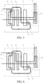
- a dehumidifier system comprises a main enclosure 10 that has an air inlet opening 11 and an air outlet opening 12 and also comprises, arranged in an interior of the main enclosure 10 a compressor based dehumidification assembly, a rotary wheel based humidification assembly, and an air blower 40 that causes air to flow through the compressor based dehumidification assembly and the rotary wheel based humidification assembly to be discharged out of the main enclosure 10.
- the compressor based dehumidification assembly comprises an evaporator 21, a condenser 22, a compressor 23, and a throttle element.
- the rotary wheel based humidification assembly comprises a dehumidification roller 31, a regeneration air blower 32, a heating element 33 and a heat exchanger 34 that includes a first heat exchange passage (not shown in the drawings) and a second heat exchange passage (not shown in the drawings) that are not in communication with each other.
- the evaporator 21, the condenser 22, the compressor 23, and the throttle element are arranged, in a circulative and communicating configuration, to form a heat pump circulation.
- the first heat exchange passage, the regeneration air blower 32, the heating element 33, and the dehumidification roller 31 are arranged, in a circulative and communicating configuration, to form a regeneration circulation airflow channel A.
- the air inlet opening 11, the second heat exchange passage, the evaporator 21, the air blower 40, and the air outlet opening 12 are arranged, in a circulative and communicating configuration, to form a first airflow channel B.
- a surrounding temperature is low temperature (less than 15°C)
- a temperature of the evaporator 21 readily becomes lower than or approaching 0° and the evaporator 21 gets frosting in an interior structure thereof.
- Combining the rotary wheel based humidification assembly as an additive means with the compressor based dehumidification assembly would allow air in the first airflow channel B to first undergo heat exchange with the heat exchanger 34.
- the air that enters the first heat exchange passage of the heat exchanger 34 has a temperature and humidity that are higher than a temperature and humidity of air entering the second heat exchange passage and an absolute temperature of the first heat exchange passage is higher than an absolute temperature of the second heat exchange passage.
- the air of the first airflow channel B passing through the heat exchanger 34 would cause the air in the first heat exchange passage to reach a temperature condition of dew point and thus turn into condensate water on an inside surface of the first heat exchange passage.
- the air of the first heat exchange passage is also increased in temperature (becoming higher than the original 15°C) due to exchange heat with the heat exchanger 34 so that with the increase of temperature of the first airflow channel B, the evaporator 21 would not get frosting due to the temperature of the air moving therein. This would resolve the issue of frosting that might occur in the compressor based dehumidification assembly due to a low temperature.
- the compressor based dehumidification assembly can now continuously operate in a low temperature and an idle operation for the purpose of defrosting can be prevented. Compared to the prior art, the capability of dehumidification is increased and the efficiency of dehumidification is improved.
- the compressor based dehumidification assembly and the rotary wheel based humidification assembly are combined with each other so that air having a high temperature is generated due to heat exchange with the heat exchanger 34 of the rotary wheel based humidification assembly, while although the evaporator 21 of the compressor based dehumidification assembly readily gets frosting in air of a low temperature, the arrangement of the first airflow channel B brings air from the heat exchanger 34 to the evaporator 21 to increase the temperature of air that enters the evaporator 21 thereby making the evaporator 21 not so easy to get frosting and thus effectively improving the dehumidification capacity of the compressor based dehumidification assembly in the low temperature.
- the rotary wheel based humidification assembly In a high temperature, the rotary wheel based humidification assembly has a low dehumidification efficiency and the rotary wheel based humidification assembly could be shut down to allow the compressor based dehumidification assembly to operate alone in order to improve the overall dehumidification efficiency of the entire system of this invention.
- the instant embodiment is shown in FIG. 1 .
- the instant embodiment comprises a first airflow channel B that is made up of the air inlet opening 11, the second heat exchange passage, the evaporator 21, the air blower 40 and the air outlet opening 12 arranged in communication with each other and a second airflow channel C made up of the air inlet opening 11, the condenser 22, the dehumidification roller 31, the air blower 40, and the air outlet opening 12 arranged in communication with each other.
- Air of the second airflow channel C enters the condenser 22 and undergoes heat exchange with the condenser 22 to bring away heat from the condenser 22.
- the air of the second airflow channel C after leaving the condenser 22, enters the dehumidification roller 31 and subjected to dehumidification by the dehumidification roller 31 to be discharged by the air blower 40 through the air outlet opening 12.
- the heat exchanger 34, the evaporator 21, the condenser 22, and the dehumidification roller 31 are arranged side by side, in a parallel arrangement, inside the main enclosure 10 with an exit of the evaporator 21 facing the condenser 22 and an air exit of the condenser 22 facing the dehumidification roller 31.
- Air of the first airflow channel B moves straightforward from the air inlet opening toward the evaporator 21, and is directly guided, after passing through the evaporator 21, toward the air outlet opening, while air of the second airflow channel C, after passing through the condenser, is directly towards the air blower 40.
- Such arrangements of the first airflow channel B and the second airflow channel C feature shortened lengths and reduced bends.
- the above-described arrangement of the four components is advantageous for shortening the lengths of the first airflow channel B and the second airflow channel C and reducing bends of these channels so that the internal arrangement of the main enclosure 10 is made neat and is easy for setting up the airflow channels.
- the air blower 40 is arranged at an outer side of the dehumidification roller 31.
- the main enclosure 10 is configured with an upper chamber and a lower chamber.
- the heat exchanger 34, the evaporator 21, the condenser 22, and the dehumidification roller 31 are arranged in the upper chamber of the main enclosure 10.
- the instant embodiment further comprises a water accumulation tank 60 for collecting and holding therein condensate water from the heat exchanger 34 and the evaporator 21.
- the compressor 23 and the water accumulation tank 60 are arranged in the lower chamber, and the water accumulation tank 60 is located under the heat exchanger 34 and the evaporator 21.
- first airflow channel B air that enters the second heat exchange passage of the heat exchanger 34 undergoes heat exchange with high-temperature and high-humidity air in the first heat exchange passage and causes the air in the first heat exchange passage to carry out first condensation and dewing of the instant embodiment.
- the air of the first airflow channel B after having been increased in temperature in the second heat exchange passage, subsequently enters the evaporator 21 to carry out second condensation and dewing of the instant embodiment, and is then discharged, through the air blower 40 and the air outlet opening 12, to outside of the main enclosure 10.
- the first airflow channel B functions to cause condensation and dewing of the high-temperature and high-humidity air of the circulation airflow channel A, allowing for normal circulation inside the circulation airflow channel A, while air of its own is subjected to condensation and dewing in the evaporator 21 to transfer heat to the evaporator 21 to maintain normal operation of the heat pump circulation of the compressor based dehumidification assembly.
- the first airflow channel B functions as a channel for heating the evaporator 21 and for moisture removing and water condensing and since it undergoes one round of water condensation, it would reduce humidity of air of the dehumidification roller 31 if allowed to pass through the dehumidification roller 31 so as to lower the dehumidification efficiency of the dehumidification roller 31, whereby a preferred way is to let it discharged to the outside directly, while the dehumidification roller 31 can be used to filter air having higher humidity to improve the dehumidification efficiency thereof.
- the dehumidification roller 31 is operable to absorb moisture from air located therein and the dehumidification roller 31 is kept in continuous rotation as being driven by a rotary electrical machine (not shown in the drawings) and continuously absorb moisture, wherein a portion of the dehumidification roller 31 that has absorbed therein moisture is rotated to a position corresponding to and facing the heating element 33.
- the regeneration air blower 32 draws dry air into the heating element 33 and the heating element 33 heats up the air, which then enters the portion of the dehumidification roller 31 corresponding to and facing the heating element 33 so that the heated, and thus high-temperature, dry air is allowed to dry the dehumidification roller 31, the air of the regeneration circulation airflow channel A, after passing the dehumidification roller 31, is turned into high-temperature and high-humidity air, which then enters the first heat exchange passage of the heat exchanger 34 to undergo heat exchange with air in the second heat exchange passage so that the air in the first heat exchange passage undergoes condensation and dewing. After passing through the heat exchanger 34, the air in the regeneration circulation airflow channel A is turned into dry air again for re-entry into the regeneration air blower 32 for the next circulation cycle.
- the instant embodiment combines the two dehumidification assemblies so as to possess the dehumidification capabilities of the two dehumidification assemblies and also eliminate the deficiency of the compressor based dehumidification assembly for operation in a low temperature to make the compressor based dehumidification assembly not ready to frost in the low temperature thereby effectively improving the dehumidification capability the dehumidifier system in a low temperature.
- the airflow channels of this embodiment have a simple and overall compact arrangement.
- a difference of the instant embodiment is that, as shown in FIG. 2 , a second airflow channel C made up of the air inlet opening 11, the condenser 22, the air blower 40, and the air outlet opening 12 that are arranged in communication with each other and a third airflow channel D made up of the air inlet opening 11, the dehumidification roller 31, the air blower 40, and the air outlet opening 12 that are arranged in communication with each other are included.
- the second airflow channel of EMBODIMENT 1 is replaced with the second airflow channel C and the third airflow channel D of this embodiment.
- air of the second airflow channel C enters from the air inlet opening 11, moves through the condenser 22 to exchange heat with the condenser 22 so as to dissipate heat from and thus cool down the condenser 22, and then discharges to the outside through the air blower 40 and the air outlet opening 12.
- High-humidity air of the third airflow channel D is drawn, through the air inlet opening 11, into the dehumidification roller 31 with moisture thereof being absorbed by the dehumidification roller 31 and then discharged to the outside through the air blower 40 and the air outlet opening 12.
- an additional airflow channel is included, yet in the instant embodiment, high-temperature air of the condenser 22 is directly charged to the outside so that the high-temperature air is prevented from heating the dehumidification roller 31 to thereby avoid lowering the dehumidification efficiency of the dehumidification roller 31.
- the dehumidification roller 31 demonstrates even higher dehumidification efficiency.
- the first airflow channel B further comprises a part of airflow channel that is connected to the condenser 22 and thus, in an overall arrangement, the air inlet opening 11, the second heat exchange passage, the evaporator 21, the condenser 22, the air blower 40, and the air outlet opening 12 are set in communication with each other in such a sequence.
- Air of the first airflow channel B moves, in sequence, through the air inlet opening 11, the second heat exchange passage, the evaporator 21, the condenser 22, the air blower 40, and the air outlet opening 12.
- the condenser 22 is included in the second airflow channel C, while in the instant embodiment, the condenser 22 is included in the first airflow channel B, wherein high-temperature air generated after passing through the condenser 22 is directly discharged outside the main enclosure 10 to prevent entry into the dehumidification roller 31 so as to help increase the dehumidification efficiency of the dehumidification roller 31.
- the instant embodiment also comprises a second airflow channel C, wherein the air inlet opening 11, the dehumidification roller 31, the air blower 40, and the air outlet opening 12 are arranged in communication with each other to form the second airflow channel C.
- Air entering the second airflow channel C is directly guided into the dehumidification roller 31, and air that passes through the dehumidification roller 31 is normal-temperature and high-humidity air and has not been heated by the condenser 22.
- air that passes through the dehumidification roller 31 may be of the same humidity, but the temperature is lower so that in the instant embodiment, the dehumidification roller 31 shows higher dehumidification efficiency.
- the first airflow channel B further comprises an airflow channel in communication with the condenser 22 and the dehumidification roller 31 and, specifically, the air inlet opening 11, the second heat exchange passage, the evaporator 21, the condenser 22, the dehumidification roller 31, the air blower 40, and the air outlet opening 12 are arranged in communication with each other in such a sequence.
- the above basic configuration of the instant embodiment provides a structural arrangement of the simplest airflow channel and the simplest main enclosure 10.
- air of the first airflow channel B moves, in sequence, through the heat exchanger 34, the evaporator 21, the condenser 22, and the dehumidification roller 31. Since air has to move through all the components, the overall air resistance is relatively large.
- the main enclosure 10 is provided therein with airflow channels for replenishment of air to allow air external of the main enclosure 10 to directly enter the evaporator 21, or to directly enter the condenser 22, or to directly enter the dehumidification roller 31, so as to increase airflow channels for intake of air, allowing a part of the external air to detour round the heat exchanger 34 for direct entry into the evaporator 21, or to simultaneously detour round the heat exchanger 34 and the evaporator 21 for direct entry into the condenser 22, or to simultaneously detour round the heat exchanger 34, the evaporator 21, and the condenser 22 for direct entry into the dehumidification roller 31.
- Such airflow channels may be provided in various alternative ways and examples are to selectively add three airflow channels for replenishment of air, which could respectively be a second airflow channel C, a third airflow channel D, and a fourth airflow channel E.
- the air inlet opening 11, the evaporator 21, the condenser 22, the dehumidification roller 31, the air blower 40, and the air outlet opening 12 are selectively set in communication with each other to form the second airflow channel C; the air inlet opening 11, the condenser 22, the dehumidification roller 31, the air blower 40, and the air outlet opening 12 are selectively in communication with each other to form the third airflow channel D; and the air inlet opening 11, the dehumidification roller 31, the air blower 40, and the air outlet opening 12 are selectively set in communication with each other to form the fourth airflow channel E.
- the first alternative way of embodiment includes adding only the second airflow channel C, wherein specifically, air flows along the second airflow channel C to move, in sequence, through the air inlet opening 11, the evaporator 21, the condenser 22, the dehumidification roller 31, the air blower 40, and the air outlet opening 12.
- High-humidity air of the second airflow channel C makes direct entry into the evaporator 21, and thus, two airflows enter the evaporator 21 together.
- the second alternative way of embodiment includes adding only the third airflow channel D, wherein specifically, air flows along the third airflow channel D to move, in sequence, through the air inlet opening 11, the condenser 22, the dehumidification roller 31, the air blower 40, and the air outlet opening 12. Since air of the first airflow channel B moves through all the components, the overall air resistance is relatively large and this makes it harder for air to reach the condenser 22 and thus, head dissipation of the condenser 22 becomes difficult. Air in the third airflow channel D may make direct entry into the condenser 22 to exchange heat with the condenser 22 to improve heat exchange with the condenser 22 and also increase the total humidity of air passing the dehumidification roller 31.
- the third alternative way of embodiment includes adding the second airflow channel C, the third airflow channel D, and the fourth airflow channel E, and thus, as compared to the above two alternative ways, air flow through the evaporator 21, the condenser 22, and the dehumidification roller 31 is increased, wherein among the three components, the dehumidification roller 31 receives the largest amount of increase of air so that the dehumidification roller 31 demonstrate a high dehumidification efficiency. Further, the air flow through the condenser 22 is larger than that of the evaporator 21 so as to provide higher heat dissipation efficiency.
- Simultaneously adding the three airflow channels allows for selectively and individually setting up the air flows of the three airflow channels so that air flow could be set at a large value for components showing insufficiency of air flow, while airflow cross-sectional area of an airflow channel that passes through a component where the demand for air flow is small can be properly reduced.
- a control valve 50 could be provided for controlling the air flow level or state of closing/opening of the second airflow channel C, the third airflow channel D, or the fourth airflow channel E.
- the instant embodiment further comprises an electric control module (not shown in the drawings) for controlling the operation of the compressor based dehumidification assembly, the rotary wheel based humidification assembly, and each individual control valve 50.
- the electric control module functions to control opening and closing of the control valve 50 and an opening angle thereof and may respond to demand of functionality as instructed and input by a user to control opening time, closing time, and opening angle adjusting time of each individual control valve 50. Additional operation may be available for control starting time and shutdown time of the compressor based dehumidification assembly and the rotary wheel based humidification assembly.
- control valves 50 in the third alternative way to respectively associated with the second airflow channel C, the third airflow channel D, the fourth airflow channel E. As shown in FIG. 8 , the three control valves 50 respectively control the second airflow channel C, the third airflow channel D, the fourth airflow channel E.
- the heat exchanger 34, the evaporator 21, the condenser 22, the dehumidification roller 31 are arranged side by side in the interior of the main enclosure 10 such that a gap is provided between the heat exchanger 34 and the evaporator 21 and forms a part of the second airflow channel C and the control valve 50 associated with the second airflow channel C is set up at an entry site of the gap to control air flow through the gap be.
- a gap is provided between the heat exchanger 34 and the condenser 22 and forms a part of the third airflow channel D and the control valve 50 associated with the third airflow channel D is set up at an entry site of the gap to control air flow through the gap between the evaporator 21 and the condenser 22.
- a gap is provided between the condenser 22 and the dehumidification roller 31 and forms a part of the fourth airflow channel E and the control valve 50 associated with the fourth airflow channel E is set up at an entry site of the gap to control air flow through the gap between the condenser 22 and the dehumidification roller 31.
- each individual control valve 50 By using the electric control module to control each individual control valve 50 to open or close, it is possible to individually open any one of the second airflow channel C, the third airflow channel D, and the fourth airflow channel E, such as individually opening the control valve 50 associated with the second airflow channel C to allow direct entry of air into the evaporator 21, or individually opening the control valve 50 associated with the fourth airflow channel E to allow direct entry of air into the dehumidification roller 31.
- any two of the control valves 50 can be combined or an operation of simultaneously opening all the control valves 50 can be made.
- the electric control module may adjust the opening angle of the control valve 50 to achieve control of air flow through each of the gaps, meaning controlling the air flow through each of the second airflow channel C, the third airflow channel D, and the fourth airflow channel E so that in use, it is possible to control the control valves 50 according to different operation environments or different user requirements for opening and closing or opening to a desired angle to allow the compressor based dehumidification assembly and the rotary wheel based humidification assembly to achieve the greatest performance thereof.
- the seventh example includes the arrangement of the control valve(s) 50 and the electric control module so that the electric control module is operable to control the opening and closing of each of the control valves 50 to achieve all the functions available for the basic configuration and the alternative seven embodiments and thus the addition of the control valve(s) 50 and the electric control module provide diversified functionality of this invention.
- control module of the present invention may make adjustment of the operation conditions of the two sets of dehumidification assembly and the control status of the three control valves so that the present invention can be used in a clothing drying mode.
- the rotary wheel based humidification assembly comprises a heating element 33 and the compressor based dehumidification assembly comprises a condenser 22.
- the two components are components that release heat.
- air when passing through the heat exchanger 34, generates an effect of temperature increasing and causes temperature drop when subsequently passes through the evaporator 21 of the system associated with the compressor 23, with a portion of moisture being condensed on the evaporator 21, and then causes temperature increase again in subsequent pass through the condenser 22, and finally causes temperature increase further again in passing through the dehumidification roller 31 with a part of moisture being further absorbed by the dehumidification roller 31.
- Air fed out of the system would have an increased temperature and a reduced level of humidity, as compared to surrounding air, providing hot dry air that is best suit for drying clothing.
- the system of the present invention due to combination of the compressor based dehumidification assembly and the rotary wheel based humidification assembly, is operable in a clothing drying process by selectively activating one of the dehumidification assemblies or both, with the electric control module, in response to the temperature and humidity of a clothing drying environment, plus message concerning the amount of clothing and the size of the clothing drying environment supplied and input by a user in order to achieve the most efficient result of clothing drying, such as the time period for drying clothing being the shortest or the clothing drying operation being carried out in a most energy-saving manner.
- the water content of the clothing is the greatest just before the dehumidifier is activated.
- a dry hot airflow having the highest available temperature applied to blow toward the clothing would quickly evaporate and remove the water.
- the electric control module may be operated to shut down one of the dehumidification assemblies to reduce energy consumption in order to increase the clothing drying efficiency ratio. Since the clothing drying efficiency of individual ones of the two dehumidification assemblies may be different according to the temperature and humidity of the clothing drying environment, electrical control operation may be such that a determination may be made to activate one of the devices according to result of researches conducted in laboratories.
- the electric control module may make a combined determination according to the clothing drying process and temperature and humidity of the environment and may be operated to simultaneously activate the two dehumidification assemblies or activate/deactivate one of the dehumidification assemblies to achieve the highest clothing drying efficiency (g/kW.h).
Landscapes
- Engineering & Computer Science (AREA)
- Chemical & Material Sciences (AREA)
- Combustion & Propulsion (AREA)
- Mechanical Engineering (AREA)
- General Engineering & Computer Science (AREA)
- Drying Of Gases (AREA)
Claims (4)
- Entfeuchtungssystem, das ein Hauptgehäuse (10) umfasst, das eine Lufteinlassöffnung (11) und eine Luftauslassöffnung (12) aufweist,
das eine Entfeuchtungsanordnung auf Kompressorbasis, eine Befeuchtungsanordnung auf Drehradbasis und ein Luftgebläse (40) umfasst, die im Inneren des Hauptgehäuses (10) angeordnet sind,wobei die Entfeuchtungsanordnung auf Kompressorbasis einen Verdampfer (21), einen Kondensator (22), einen Kompressor (23) und ein Drosselelement umfasst;wobei die Befeuchtungsanordnung auf Drehradbasis eine Entfeuchtungsrolle (31), ein Regenerationsluftgebläse (32), ein Heizelement (33) und einen Wärmetauscher (34) umfasst, der einen ersten Wärmetauschdurchgang und einen zweiten Wärmetauschdurchgang enthält, die nicht in Verbindung miteinander stehen;wobei der erste Wärmetauschdurchgang, das Regenerationsluftgebläse (32), das Heizelement (33) und die Entfeuchtungsrolle (31) in einer zirkulierenden und kommunizierenden Konfiguration angeordnet sind, um einen Regenerationszirkulationsluftstromkanal (A) zu bilden, in dem sich Luft in einer geschlossenen Schleife bewegt, während sie von dem Regenerationsluftgebläse (32) durch das Heizelement (33) und die Entfeuchtungsrolle (31) angetrieben wird, um weiter durch den ersten Wärmetauschdurchgang des Wärmetauschers (34) zu strömen, um zu dem Regenerationsluftgebläse (32) zurückzukehren; undwobei die Lufteinlassöffnung (11), der zweite Wärmetauschdurchgang, der Verdampfer (21), das Luftgebläse (40) und die Luftauslassöffnung (12) in einer zirkulierenden und kommunizierenden Konfiguration angeordnet sind, um einen ersten Luftstromkanal (B) zu bilden, in dem sich Luft in einer offenen Schleife bewegt, indem sie sich zuerst von der Lufteinlassöffnung (11) durch den zweiten Wärmetauschdurchgang des Wärmetauschers (34) und den Verdampfer (21) bewegt, um durch das Luftgebläse (40) angetrieben zu werden, um durch die Luftauslassöffnung (12) auszuströmen, undwobei ein zweiter Luftstromkanal (C) aus der Lufteinlassöffnung (11), dem Kondensator (22), der Entfeuchtungsrolle (31), dem Luftgebläse (40) und der Luftauslassöffnung (12) gebildet wird, die angeordnet sind, um miteinander zu kommunizieren. - Entfeuchtungssystem nach Anspruch 1, gekennzeichnet dadurch, dass der erste Luftstromkanal (B) ferner einen Teil des Luftstromkanals umfasst, der in Verbindung mit dem Kondensator (22) steht, wobei die Lufteinlassöffnung (11), der zweite Wärmetauschdurchgang, der Verdampfer (21), der Kondensator (22), das Luftgebläse (40) und die Luftauslassöffnung (12) angeordnet sind, um nacheinander miteinander zu kommunizieren.
- Entfeuchtungssystem nach Anspruch 2, gekennzeichnet dadurch, dass der erste Luftstromkanal (B) ferner einen Teil des Luftstromkanals umfasst, der in Verbindung mit der Entfeuchtungsrolle (31) steht, wobei die Lufteinlassöffnung (11), der zweite Wärmetauschdurchgang, der Verdampfer (21), der Kondensator (22), die Entfeuchtungsrolle (31), das Luftgebläse (40) und die Luftauslassöffnung (12) angeordnet sind, um nacheinander miteinander zu kommunizieren.
- Entfeuchtungssystem nach einem der Ansprüche 1-3, gekennzeichnet dadurch, dass der Wärmetauscher (34), der Verdampfer (21), der Kondensator (22) und die Entfeuchtungsrolle (31) nebeneinander im Inneren des Hauptgehäuses (10) angeordnet sind und der Verdampfer (21) einen Ausgang aufweist, der dem Kondensator (22) zugewandt ist, und der Kondensator (22) einen Ausgang aufweist, der der Entfeuchtungsrolle (31) zugewandt ist.
Applications Claiming Priority (2)
| Application Number | Priority Date | Filing Date | Title |
|---|---|---|---|
| CN201620720950.6U CN205957367U (zh) | 2016-07-08 | 2016-07-08 | 除湿机系统 |
| PCT/CN2016/090908 WO2018006448A1 (zh) | 2016-07-08 | 2016-07-21 | 除湿机系统 |
Publications (3)
| Publication Number | Publication Date |
|---|---|
| EP3483515A1 EP3483515A1 (de) | 2019-05-15 |
| EP3483515A4 EP3483515A4 (de) | 2020-03-11 |
| EP3483515B1 true EP3483515B1 (de) | 2023-09-06 |
Family
ID=57970368
Family Applications (1)
| Application Number | Title | Priority Date | Filing Date |
|---|---|---|---|
| EP16907952.2A Active EP3483515B1 (de) | 2016-07-08 | 2016-07-21 | Entfeuchtungssystem |
Country Status (3)
| Country | Link |
|---|---|
| EP (1) | EP3483515B1 (de) |
| CN (1) | CN205957367U (de) |
| WO (1) | WO2018006448A1 (de) |
Families Citing this family (8)
| Publication number | Priority date | Publication date | Assignee | Title |
|---|---|---|---|---|
| CN106949572B (zh) * | 2017-03-10 | 2022-09-23 | 江苏苏净集团有限公司 | 一种融霜除湿机及转轮式除湿机融霜方法 |
| CN107560016B (zh) * | 2017-09-27 | 2023-12-12 | 珠海格力电器股份有限公司 | 除湿系统及具有该除湿系统的除湿机 |
| CN110006111B (zh) * | 2019-04-23 | 2024-06-21 | 中国建筑科学研究院有限公司 | 环境控制一体机 |
| CN112594801A (zh) * | 2020-12-16 | 2021-04-02 | 广州奥斯德科技有限公司 | 节能热泵式转轮除湿机组 |
| CN114570160A (zh) * | 2022-03-03 | 2022-06-03 | 杭州瑞亚电气有限公司 | 一种单风机精滤转轮除湿机 |
| CN114811766A (zh) * | 2022-05-05 | 2022-07-29 | 安徽正刚新能源科技有限公司 | 一种复叠式过冷跨临界二氧化碳冷热联供转轮除湿装置 |
| CN116558260B (zh) * | 2023-04-03 | 2025-06-24 | 广东益康生环保设备有限公司 | 一种多级回热除湿的热泵分区干燥系统 |
| CN120332839B (zh) * | 2025-05-30 | 2026-01-16 | 杭州工言节能科技有限公司 | 一种吸尘式新风系统及其控制方法 |
Family Cites Families (8)
| Publication number | Priority date | Publication date | Assignee | Title |
|---|---|---|---|---|
| US3483649A (en) * | 1968-10-29 | 1969-12-16 | Us Interior | Electrical trawl net system |
| US5816065A (en) * | 1996-01-12 | 1998-10-06 | Ebara Corporation | Desiccant assisted air conditioning system |
| US5732562A (en) * | 1996-08-13 | 1998-03-31 | Moratalla; Jose M. | Method and apparatus for regenerating desiccants in a closed cycle |
| US9885486B2 (en) * | 2010-08-27 | 2018-02-06 | Nortek Air Solutions Canada, Inc. | Heat pump humidifier and dehumidifier system and method |
| CN202040908U (zh) * | 2011-03-23 | 2011-11-16 | 广东申菱空调设备有限公司 | 冷凝热回收式复合型除湿机 |
| CN102384539B (zh) * | 2011-11-11 | 2013-08-21 | 江苏大学 | 一种空气源热泵与转轮除湿组合的复合空调系统 |
| CN105276710A (zh) * | 2014-07-25 | 2016-01-27 | 江苏豪森维尔科技有限公司 | 一种热回收式转轮除湿机组 |
| CN105465914A (zh) * | 2014-09-11 | 2016-04-06 | 南京五洲制冷集团有限公司 | 一种低温再生复合式转轮除湿机组 |
-
2016
- 2016-07-08 CN CN201620720950.6U patent/CN205957367U/zh active Active
- 2016-07-21 EP EP16907952.2A patent/EP3483515B1/de active Active
- 2016-07-21 WO PCT/CN2016/090908 patent/WO2018006448A1/zh not_active Ceased
Also Published As
| Publication number | Publication date |
|---|---|
| EP3483515A4 (de) | 2020-03-11 |
| EP3483515A1 (de) | 2019-05-15 |
| CN205957367U (zh) | 2017-02-15 |
| WO2018006448A1 (zh) | 2018-01-11 |
Similar Documents
| Publication | Publication Date | Title |
|---|---|---|
| EP3483515B1 (de) | Entfeuchtungssystem | |
| CN107490283B (zh) | 可快速升温的热回收型调温热泵干燥装置及其运行方法 | |
| CN104233735B (zh) | 一种热泵干衣机及干衣方法 | |
| CN103774398B (zh) | 具有根据驱动模式变化的膨胀阀的衣物处理设备 | |
| JP5098346B2 (ja) | 換気空調装置 | |
| CN106480682B (zh) | 一种高效的直排式热泵干衣机 | |
| CN108955219A (zh) | 热泵烘干系统 | |
| KR101363864B1 (ko) | 에너지절감형 특수 공기조화기 | |
| CN205077292U (zh) | 干衣机 | |
| JP2008116145A (ja) | ヒートポンプ式除湿空調機 | |
| CN110763005B (zh) | 一种热泵型双流体除湿升温干燥机及干燥室 | |
| US10612184B2 (en) | Hydronic drying machine | |
| CN106255858A (zh) | 混合热泵设备 | |
| CN111692779A (zh) | 一种用于海苔烘干的湿冷双效回收型高效热泵机组 | |
| CN111076302A (zh) | 新风空调室内机、新风空调器及其控制方法 | |
| KR101422197B1 (ko) | 고정밀 습도제어형 말단재열 공기조화기 | |
| KR102246320B1 (ko) | 공기 조화 시스템 | |
| EP3133352B1 (de) | Entfeuchtungs- und kühlvorrichtung | |
| CN108168225B (zh) | 一种分流型热泵干燥系统 | |
| CN201867023U (zh) | 新型高温烘干机 | |
| KR102920400B1 (ko) | 공기 조화기 | |
| CN102538299B (zh) | 热泵式可调温湿度机组 | |
| CN207050339U (zh) | 一种空气源一体式烘干抽湿机及系统 | |
| CN224162947U (zh) | 一种闭式烘干系统及闭式烘干机组 | |
| CN216281895U (zh) | 新风设备 |
Legal Events
| Date | Code | Title | Description |
|---|---|---|---|
| STAA | Information on the status of an ep patent application or granted ep patent |
Free format text: STATUS: THE INTERNATIONAL PUBLICATION HAS BEEN MADE |
|
| PUAI | Public reference made under article 153(3) epc to a published international application that has entered the european phase |
Free format text: ORIGINAL CODE: 0009012 |
|
| STAA | Information on the status of an ep patent application or granted ep patent |
Free format text: STATUS: REQUEST FOR EXAMINATION WAS MADE |
|
| 17P | Request for examination filed |
Effective date: 20180124 |
|
| AK | Designated contracting states |
Kind code of ref document: A1 Designated state(s): AL AT BE BG CH CY CZ DE DK EE ES FI FR GB GR HR HU IE IS IT LI LT LU LV MC MK MT NL NO PL PT RO RS SE SI SK SM TR |
|
| AX | Request for extension of the european patent |
Extension state: BA ME |
|
| DAV | Request for validation of the european patent (deleted) | ||
| DAX | Request for extension of the european patent (deleted) | ||
| A4 | Supplementary search report drawn up and despatched |
Effective date: 20200210 |
|
| RIC1 | Information provided on ipc code assigned before grant |
Ipc: F24F 3/00 20060101ALI20200204BHEP Ipc: F24F 3/14 20060101AFI20200204BHEP Ipc: F24F 11/41 20180101ALI20200204BHEP Ipc: F24F 13/30 20060101ALI20200204BHEP |
|
| STAA | Information on the status of an ep patent application or granted ep patent |
Free format text: STATUS: EXAMINATION IS IN PROGRESS |
|
| 17Q | First examination report despatched |
Effective date: 20211223 |
|
| GRAP | Despatch of communication of intention to grant a patent |
Free format text: ORIGINAL CODE: EPIDOSNIGR1 |
|
| STAA | Information on the status of an ep patent application or granted ep patent |
Free format text: STATUS: GRANT OF PATENT IS INTENDED |
|
| RIC1 | Information provided on ipc code assigned before grant |
Ipc: F24F 3/00 20060101ALI20230317BHEP Ipc: F24F 11/41 20180101ALI20230317BHEP Ipc: F24F 13/30 20060101ALI20230317BHEP Ipc: F24F 3/14 20060101AFI20230317BHEP |
|
| INTG | Intention to grant announced |
Effective date: 20230405 |
|
| GRAS | Grant fee paid |
Free format text: ORIGINAL CODE: EPIDOSNIGR3 |
|
| GRAA | (expected) grant |
Free format text: ORIGINAL CODE: 0009210 |
|
| STAA | Information on the status of an ep patent application or granted ep patent |
Free format text: STATUS: THE PATENT HAS BEEN GRANTED |
|
| AK | Designated contracting states |
Kind code of ref document: B1 Designated state(s): AL AT BE BG CH CY CZ DE DK EE ES FI FR GB GR HR HU IE IS IT LI LT LU LV MC MK MT NL NO PL PT RO RS SE SI SK SM TR |
|
| REG | Reference to a national code |
Ref country code: GB Ref legal event code: FG4D |
|
| REG | Reference to a national code |
Ref country code: CH Ref legal event code: EP |
|
| REG | Reference to a national code |
Ref country code: IE Ref legal event code: FG4D |
|
| REG | Reference to a national code |
Ref country code: DE Ref legal event code: R096 Ref document number: 602016082667 Country of ref document: DE |
|
| REG | Reference to a national code |
Ref country code: LT Ref legal event code: MG9D |
|
| REG | Reference to a national code |
Ref country code: NL Ref legal event code: MP Effective date: 20230906 |
|
| PG25 | Lapsed in a contracting state [announced via postgrant information from national office to epo] |
Ref country code: GR Free format text: LAPSE BECAUSE OF FAILURE TO SUBMIT A TRANSLATION OF THE DESCRIPTION OR TO PAY THE FEE WITHIN THE PRESCRIBED TIME-LIMIT Effective date: 20231207 |
|
| PG25 | Lapsed in a contracting state [announced via postgrant information from national office to epo] |
Ref country code: SE Free format text: LAPSE BECAUSE OF FAILURE TO SUBMIT A TRANSLATION OF THE DESCRIPTION OR TO PAY THE FEE WITHIN THE PRESCRIBED TIME-LIMIT Effective date: 20230906 Ref country code: RS Free format text: LAPSE BECAUSE OF FAILURE TO SUBMIT A TRANSLATION OF THE DESCRIPTION OR TO PAY THE FEE WITHIN THE PRESCRIBED TIME-LIMIT Effective date: 20230906 Ref country code: NO Free format text: LAPSE BECAUSE OF FAILURE TO SUBMIT A TRANSLATION OF THE DESCRIPTION OR TO PAY THE FEE WITHIN THE PRESCRIBED TIME-LIMIT Effective date: 20231206 Ref country code: LV Free format text: LAPSE BECAUSE OF FAILURE TO SUBMIT A TRANSLATION OF THE DESCRIPTION OR TO PAY THE FEE WITHIN THE PRESCRIBED TIME-LIMIT Effective date: 20230906 Ref country code: LT Free format text: LAPSE BECAUSE OF FAILURE TO SUBMIT A TRANSLATION OF THE DESCRIPTION OR TO PAY THE FEE WITHIN THE PRESCRIBED TIME-LIMIT Effective date: 20230906 Ref country code: HR Free format text: LAPSE BECAUSE OF FAILURE TO SUBMIT A TRANSLATION OF THE DESCRIPTION OR TO PAY THE FEE WITHIN THE PRESCRIBED TIME-LIMIT Effective date: 20230906 Ref country code: GR Free format text: LAPSE BECAUSE OF FAILURE TO SUBMIT A TRANSLATION OF THE DESCRIPTION OR TO PAY THE FEE WITHIN THE PRESCRIBED TIME-LIMIT Effective date: 20231207 Ref country code: FI Free format text: LAPSE BECAUSE OF FAILURE TO SUBMIT A TRANSLATION OF THE DESCRIPTION OR TO PAY THE FEE WITHIN THE PRESCRIBED TIME-LIMIT Effective date: 20230906 |
|
| REG | Reference to a national code |
Ref country code: AT Ref legal event code: MK05 Ref document number: 1609007 Country of ref document: AT Kind code of ref document: T Effective date: 20230906 |
|
| PG25 | Lapsed in a contracting state [announced via postgrant information from national office to epo] |
Ref country code: NL Free format text: LAPSE BECAUSE OF FAILURE TO SUBMIT A TRANSLATION OF THE DESCRIPTION OR TO PAY THE FEE WITHIN THE PRESCRIBED TIME-LIMIT Effective date: 20230906 |
|
| PG25 | Lapsed in a contracting state [announced via postgrant information from national office to epo] |
Ref country code: IS Free format text: LAPSE BECAUSE OF FAILURE TO SUBMIT A TRANSLATION OF THE DESCRIPTION OR TO PAY THE FEE WITHIN THE PRESCRIBED TIME-LIMIT Effective date: 20240106 |
|
| PG25 | Lapsed in a contracting state [announced via postgrant information from national office to epo] |
Ref country code: AT Free format text: LAPSE BECAUSE OF FAILURE TO SUBMIT A TRANSLATION OF THE DESCRIPTION OR TO PAY THE FEE WITHIN THE PRESCRIBED TIME-LIMIT Effective date: 20230906 |
|
| PG25 | Lapsed in a contracting state [announced via postgrant information from national office to epo] |
Ref country code: ES Free format text: LAPSE BECAUSE OF FAILURE TO SUBMIT A TRANSLATION OF THE DESCRIPTION OR TO PAY THE FEE WITHIN THE PRESCRIBED TIME-LIMIT Effective date: 20230906 |
|
| PG25 | Lapsed in a contracting state [announced via postgrant information from national office to epo] |
Ref country code: SM Free format text: LAPSE BECAUSE OF FAILURE TO SUBMIT A TRANSLATION OF THE DESCRIPTION OR TO PAY THE FEE WITHIN THE PRESCRIBED TIME-LIMIT Effective date: 20230906 Ref country code: RO Free format text: LAPSE BECAUSE OF FAILURE TO SUBMIT A TRANSLATION OF THE DESCRIPTION OR TO PAY THE FEE WITHIN THE PRESCRIBED TIME-LIMIT Effective date: 20230906 Ref country code: IS Free format text: LAPSE BECAUSE OF FAILURE TO SUBMIT A TRANSLATION OF THE DESCRIPTION OR TO PAY THE FEE WITHIN THE PRESCRIBED TIME-LIMIT Effective date: 20240106 Ref country code: ES Free format text: LAPSE BECAUSE OF FAILURE TO SUBMIT A TRANSLATION OF THE DESCRIPTION OR TO PAY THE FEE WITHIN THE PRESCRIBED TIME-LIMIT Effective date: 20230906 Ref country code: EE Free format text: LAPSE BECAUSE OF FAILURE TO SUBMIT A TRANSLATION OF THE DESCRIPTION OR TO PAY THE FEE WITHIN THE PRESCRIBED TIME-LIMIT Effective date: 20230906 Ref country code: CZ Free format text: LAPSE BECAUSE OF FAILURE TO SUBMIT A TRANSLATION OF THE DESCRIPTION OR TO PAY THE FEE WITHIN THE PRESCRIBED TIME-LIMIT Effective date: 20230906 Ref country code: AT Free format text: LAPSE BECAUSE OF FAILURE TO SUBMIT A TRANSLATION OF THE DESCRIPTION OR TO PAY THE FEE WITHIN THE PRESCRIBED TIME-LIMIT Effective date: 20230906 Ref country code: PT Free format text: LAPSE BECAUSE OF FAILURE TO SUBMIT A TRANSLATION OF THE DESCRIPTION OR TO PAY THE FEE WITHIN THE PRESCRIBED TIME-LIMIT Effective date: 20240108 Ref country code: SK Free format text: LAPSE BECAUSE OF FAILURE TO SUBMIT A TRANSLATION OF THE DESCRIPTION OR TO PAY THE FEE WITHIN THE PRESCRIBED TIME-LIMIT Effective date: 20230906 |
|
| PG25 | Lapsed in a contracting state [announced via postgrant information from national office to epo] |
Ref country code: PL Free format text: LAPSE BECAUSE OF FAILURE TO SUBMIT A TRANSLATION OF THE DESCRIPTION OR TO PAY THE FEE WITHIN THE PRESCRIBED TIME-LIMIT Effective date: 20230906 Ref country code: IT Free format text: LAPSE BECAUSE OF FAILURE TO SUBMIT A TRANSLATION OF THE DESCRIPTION OR TO PAY THE FEE WITHIN THE PRESCRIBED TIME-LIMIT Effective date: 20230906 |
|
| REG | Reference to a national code |
Ref country code: DE Ref legal event code: R097 Ref document number: 602016082667 Country of ref document: DE |
|
| PG25 | Lapsed in a contracting state [announced via postgrant information from national office to epo] |
Ref country code: DK Free format text: LAPSE BECAUSE OF FAILURE TO SUBMIT A TRANSLATION OF THE DESCRIPTION OR TO PAY THE FEE WITHIN THE PRESCRIBED TIME-LIMIT Effective date: 20230906 |
|
| PLBE | No opposition filed within time limit |
Free format text: ORIGINAL CODE: 0009261 |
|
| STAA | Information on the status of an ep patent application or granted ep patent |
Free format text: STATUS: NO OPPOSITION FILED WITHIN TIME LIMIT |
|
| PG25 | Lapsed in a contracting state [announced via postgrant information from national office to epo] |
Ref country code: DK Free format text: LAPSE BECAUSE OF FAILURE TO SUBMIT A TRANSLATION OF THE DESCRIPTION OR TO PAY THE FEE WITHIN THE PRESCRIBED TIME-LIMIT Effective date: 20230906 Ref country code: SI Free format text: LAPSE BECAUSE OF FAILURE TO SUBMIT A TRANSLATION OF THE DESCRIPTION OR TO PAY THE FEE WITHIN THE PRESCRIBED TIME-LIMIT Effective date: 20230906 |
|
| 26N | No opposition filed |
Effective date: 20240607 |
|
| PG25 | Lapsed in a contracting state [announced via postgrant information from national office to epo] |
Ref country code: BG Free format text: LAPSE BECAUSE OF FAILURE TO SUBMIT A TRANSLATION OF THE DESCRIPTION OR TO PAY THE FEE WITHIN THE PRESCRIBED TIME-LIMIT Effective date: 20230906 |
|
| PG25 | Lapsed in a contracting state [announced via postgrant information from national office to epo] |
Ref country code: BG Free format text: LAPSE BECAUSE OF FAILURE TO SUBMIT A TRANSLATION OF THE DESCRIPTION OR TO PAY THE FEE WITHIN THE PRESCRIBED TIME-LIMIT Effective date: 20230906 |
|
| REG | Reference to a national code |
Ref country code: DE Ref legal event code: R119 Ref document number: 602016082667 Country of ref document: DE |
|
| PG25 | Lapsed in a contracting state [announced via postgrant information from national office to epo] |
Ref country code: MC Free format text: LAPSE BECAUSE OF FAILURE TO SUBMIT A TRANSLATION OF THE DESCRIPTION OR TO PAY THE FEE WITHIN THE PRESCRIBED TIME-LIMIT Effective date: 20230906 |
|
| REG | Reference to a national code |
Ref country code: CH Ref legal event code: PL |
|
| PG25 | Lapsed in a contracting state [announced via postgrant information from national office to epo] |
Ref country code: LU Free format text: LAPSE BECAUSE OF NON-PAYMENT OF DUE FEES Effective date: 20240721 |
|
| PG25 | Lapsed in a contracting state [announced via postgrant information from national office to epo] |
Ref country code: LU Free format text: LAPSE BECAUSE OF NON-PAYMENT OF DUE FEES Effective date: 20240721 |
|
| PG25 | Lapsed in a contracting state [announced via postgrant information from national office to epo] |
Ref country code: DE Free format text: LAPSE BECAUSE OF NON-PAYMENT OF DUE FEES Effective date: 20250201 |
|
| PG25 | Lapsed in a contracting state [announced via postgrant information from national office to epo] |
Ref country code: CH Free format text: LAPSE BECAUSE OF NON-PAYMENT OF DUE FEES Effective date: 20240731 Ref country code: BE Free format text: LAPSE BECAUSE OF NON-PAYMENT OF DUE FEES Effective date: 20240731 |
|
| PG25 | Lapsed in a contracting state [announced via postgrant information from national office to epo] |
Ref country code: FR Free format text: LAPSE BECAUSE OF NON-PAYMENT OF DUE FEES Effective date: 20240731 |
|
| REG | Reference to a national code |
Ref country code: BE Ref legal event code: MM Effective date: 20240731 |
|
| PG25 | Lapsed in a contracting state [announced via postgrant information from national office to epo] |
Ref country code: IE Free format text: LAPSE BECAUSE OF NON-PAYMENT OF DUE FEES Effective date: 20240721 |
|
| PGFP | Annual fee paid to national office [announced via postgrant information from national office to epo] |
Ref country code: GB Payment date: 20250716 Year of fee payment: 10 |
|
| PG25 | Lapsed in a contracting state [announced via postgrant information from national office to epo] |
Ref country code: CY Free format text: LAPSE BECAUSE OF FAILURE TO SUBMIT A TRANSLATION OF THE DESCRIPTION OR TO PAY THE FEE WITHIN THE PRESCRIBED TIME-LIMIT; INVALID AB INITIO Effective date: 20160721 |
|
| PG25 | Lapsed in a contracting state [announced via postgrant information from national office to epo] |
Ref country code: HU Free format text: LAPSE BECAUSE OF FAILURE TO SUBMIT A TRANSLATION OF THE DESCRIPTION OR TO PAY THE FEE WITHIN THE PRESCRIBED TIME-LIMIT; INVALID AB INITIO Effective date: 20160721 |