EP3483032B1 - System und verfahren zum schutz der kommunikation zwischen einer balise und einem geführten fahrzeug vor übersprechen - Google Patents
System und verfahren zum schutz der kommunikation zwischen einer balise und einem geführten fahrzeug vor übersprechen Download PDFInfo
- Publication number
- EP3483032B1 EP3483032B1 EP17290146.4A EP17290146A EP3483032B1 EP 3483032 B1 EP3483032 B1 EP 3483032B1 EP 17290146 A EP17290146 A EP 17290146A EP 3483032 B1 EP3483032 B1 EP 3483032B1
- Authority
- EP
- European Patent Office
- Prior art keywords
- signal
- board device
- test
- receiver
- test signal
- Prior art date
- Legal status (The legal status is an assumption and is not a legal conclusion. Google has not performed a legal analysis and makes no representation as to the accuracy of the status listed.)
- Active
Links
Images

Classifications
-
- B—PERFORMING OPERATIONS; TRANSPORTING
- B61—RAILWAYS
- B61L—GUIDING RAILWAY TRAFFIC; ENSURING THE SAFETY OF RAILWAY TRAFFIC
- B61L15/00—Indicators provided on the vehicle or train for signalling purposes
- B61L15/0018—Communication with or on the vehicle or train
- B61L15/0027—Radio-based, e.g. using GSM-R
-
- B—PERFORMING OPERATIONS; TRANSPORTING
- B61—RAILWAYS
- B61L—GUIDING RAILWAY TRAFFIC; ENSURING THE SAFETY OF RAILWAY TRAFFIC
- B61L3/00—Devices along the route for controlling devices on the vehicle or train, e.g. to release brake or to operate a warning signal
- B61L3/02—Devices along the route for controlling devices on the vehicle or train, e.g. to release brake or to operate a warning signal at selected places along the route, e.g. intermittent control simultaneous mechanical and electrical control
- B61L3/08—Devices along the route for controlling devices on the vehicle or train, e.g. to release brake or to operate a warning signal at selected places along the route, e.g. intermittent control simultaneous mechanical and electrical control controlling electrically
- B61L3/12—Devices along the route for controlling devices on the vehicle or train, e.g. to release brake or to operate a warning signal at selected places along the route, e.g. intermittent control simultaneous mechanical and electrical control controlling electrically using magnetic or electrostatic induction; using radio waves
- B61L3/121—Devices along the route for controlling devices on the vehicle or train, e.g. to release brake or to operate a warning signal at selected places along the route, e.g. intermittent control simultaneous mechanical and electrical control controlling electrically using magnetic or electrostatic induction; using radio waves using magnetic induction
-
- B—PERFORMING OPERATIONS; TRANSPORTING
- B61—RAILWAYS
- B61L—GUIDING RAILWAY TRAFFIC; ENSURING THE SAFETY OF RAILWAY TRAFFIC
- B61L3/00—Devices along the route for controlling devices on the vehicle or train, e.g. to release brake or to operate a warning signal
- B61L3/02—Devices along the route for controlling devices on the vehicle or train, e.g. to release brake or to operate a warning signal at selected places along the route, e.g. intermittent control simultaneous mechanical and electrical control
- B61L3/08—Devices along the route for controlling devices on the vehicle or train, e.g. to release brake or to operate a warning signal at selected places along the route, e.g. intermittent control simultaneous mechanical and electrical control controlling electrically
- B61L3/12—Devices along the route for controlling devices on the vehicle or train, e.g. to release brake or to operate a warning signal at selected places along the route, e.g. intermittent control simultaneous mechanical and electrical control controlling electrically using magnetic or electrostatic induction; using radio waves
-
- H—ELECTRICITY
- H04—ELECTRIC COMMUNICATION TECHNIQUE
- H04B—TRANSMISSION
- H04B1/00—Details of transmission systems, not covered by a single one of groups H04B3/00 - H04B13/00; Details of transmission systems not characterised by the medium used for transmission
- H04B1/06—Receivers
- H04B1/10—Means associated with receiver for limiting or suppressing noise or interference
-
- H—ELECTRICITY
- H04—ELECTRIC COMMUNICATION TECHNIQUE
- H04B—TRANSMISSION
- H04B7/00—Radio transmission systems, i.e. using radiation field
- H04B7/02—Diversity systems; Multi-antenna system, i.e. transmission or reception using multiple antennas
- H04B7/04—Diversity systems; Multi-antenna system, i.e. transmission or reception using multiple antennas using two or more spaced independent antennas
- H04B7/08—Diversity systems; Multi-antenna system, i.e. transmission or reception using multiple antennas using two or more spaced independent antennas at the receiving station
-
- B—PERFORMING OPERATIONS; TRANSPORTING
- B61—RAILWAYS
- B61L—GUIDING RAILWAY TRAFFIC; ENSURING THE SAFETY OF RAILWAY TRAFFIC
- B61L15/00—Indicators provided on the vehicle or train for signalling purposes
- B61L15/0081—On-board diagnosis or maintenance
-
- B—PERFORMING OPERATIONS; TRANSPORTING
- B61—RAILWAYS
- B61L—GUIDING RAILWAY TRAFFIC; ENSURING THE SAFETY OF RAILWAY TRAFFIC
- B61L3/00—Devices along the route for controlling devices on the vehicle or train, e.g. to release brake or to operate a warning signal
- B61L3/02—Devices along the route for controlling devices on the vehicle or train, e.g. to release brake or to operate a warning signal at selected places along the route, e.g. intermittent control simultaneous mechanical and electrical control
- B61L3/08—Devices along the route for controlling devices on the vehicle or train, e.g. to release brake or to operate a warning signal at selected places along the route, e.g. intermittent control simultaneous mechanical and electrical control controlling electrically
- B61L3/12—Devices along the route for controlling devices on the vehicle or train, e.g. to release brake or to operate a warning signal at selected places along the route, e.g. intermittent control simultaneous mechanical and electrical control controlling electrically using magnetic or electrostatic induction; using radio waves
- B61L3/121—Devices along the route for controlling devices on the vehicle or train, e.g. to release brake or to operate a warning signal at selected places along the route, e.g. intermittent control simultaneous mechanical and electrical control controlling electrically using magnetic or electrostatic induction; using radio waves using magnetic induction
- B61L2003/123—French standard for inductive train protection, called "Contrôle de vitesse par balises" [KVB]
-
- B—PERFORMING OPERATIONS; TRANSPORTING
- B61—RAILWAYS
- B61L—GUIDING RAILWAY TRAFFIC; ENSURING THE SAFETY OF RAILWAY TRAFFIC
- B61L27/00—Central railway traffic control systems; Trackside control; Communication systems specially adapted therefor
- B61L27/60—Testing or simulation
-
- B—PERFORMING OPERATIONS; TRANSPORTING
- B61—RAILWAYS
- B61L—GUIDING RAILWAY TRAFFIC; ENSURING THE SAFETY OF RAILWAY TRAFFIC
- B61L27/00—Central railway traffic control systems; Trackside control; Communication systems specially adapted therefor
- B61L27/70—Details of trackside communication
Definitions
- the present invention concerns a system and a method for protecting a communication between a balise and a guided vehicle on-board device from cross-talk, wherein balises are installed at points along a route followed by the guided vehicle.
- the present invention is related to the problematic of cross-talk that may occur when an on-board device of a guided vehicle receives a signal (said signal being typically a "telegram") from a balise mounted on a track of a railway network that is followed by the guided vehicle.
- Cross-talk refers to an undesired effect in the on-board device created by the reception by said on-board device of an additional signal (also called hereafter “cross-talk signal”) apart from the signal received from the balise it is reading, i.e. said telegram.
- cross-talk signal there is cross-talk when a telegram is read from a balise that should not be read, like a balise on another track.
- the cross-talk signal might be received by an on-board device while no signal is expected, leading for instance to an incorrect localization of the guided vehicle.
- balises also called beacons
- said balise is an Eurobalise, i.e. a balise which complies with the European Train Control System, and is installed between rails of a railway followed by the guided vehicle.
- “Guided vehicle” refers to public transport means such as buses, trolleybuses, streetcars, subways, trains or train units, etc., as well as load transporting means such as, for example, overhead traveling cranes, for which safety is a very important factor and which are guided along a route or railway for instance by at least one rail, in particular by two rails between which balises are placed.
- the document GB 2 027 244 A discloses a cross-talk limitation by orientation of the emitted fields and thus limiting the side band dispersion.
- An objective of the present invention is to propose a new system and method for protecting from cross-talk a communication between a balise and a guided vehicle on-board device, which are simple, efficient, and whose failure might be easily and cost efficiently detected.
- the present invention proposes to incorporate into a reception signal outputted by an antenna of a receiver of the on-board device a test signal acting as a noise to limit the sensitivity of the on-board device as disclosed in the objects of independent claims 1 and 9.
- a test signal acting as a noise to limit the sensitivity of the on-board device as disclosed in the objects of independent claims 1 and 9.
- the present invention proposes notably an on-board device for reading a telegram of a balise installed at a point along a route followed by a guided vehicle in which said on-board device is designed to be installed, said on-board device comprising:
- the present invention concerns also a method for protecting from cross-talk an on-board device configured for reading telegrams of balises installed at points along a route followed by a guided vehicle in which said on-board device is installed, the method comprising the following steps:
- the test signal is a known signal whose characteristics are known and stored within the on-board device in order to enable the latter to extract the test signal from the reception signal for test and verification purposes.
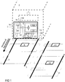
- FIG. 1 shows an on-board device 1 according to the invention mounted on-board a guided vehicle 2 which is configured to follow a route defined by a pair of rails 3.
- a balise 4 is installed on the route or rail track followed by the guided vehicle 2, for example between the rails 3.
- the rail track may comprise several balises 4 forming a system of balises 4, each balise being configured to exchange information with the guided vehicle 2 when the latter passes at proximity, for instance above/over, said balise 4.
- the balise 4 and the on-board device 1 exchange information by means of electromagnetic signals transmitted from the balise 4, respectively on-board device 1, to the on-board device 1, respectively balise 4.
- undesired cross-talk signal might be received from another balise 41 installed on an adjacent route defined by another pair of rails 31 in proximity of the balise 4 or any other component which might generate an electromagnetic field from a signal sent by the on-board device 1 and capable of interfering with the signal received by the on-board device 1 from the balise 4.
- a cross-talk signal emitted by another balise 42 installed on said adjacent route might be received by the on-board device 1 while no balise is installed on the route followed by said guided vehicle 2.
- the on-board device 1 comprises preferentially an emitter 11, a receiver 12, a processing unit 14 and a test component 13.
- the emitter 11 is for instance configured for remotely powering the balise 4 by means of radiant energy, and/or for transmitting an initialization signal to the balise, and/or for storing data within the balise 4.
- the balise is configured for sending an electromagnetic signal, i.e. the so-called telegram, comprising encoded information to the receiver 12 of the on-board device.
- the balise might be a self-powered balise.
- the balise may send an electromagnetic signal to the receiver when the latter is detected, or may send said electromagnetic signal to the receiver in response to its powering by the emitter 11.
- An antenna of the receiver 12 is configured for receiving the electromagnetic signal of the balise and outputting, from its interaction with said electromagnetic signal, a reception signal S1 that is sent to the processing unit 14 in order to determine the information provided by the balise 4.
- Said reception signal S1 is the signal outputted by the antenna of the receiver 12 when said antenna induces a current from its interaction with electromagnetic radiations. If the electromagnetic radiation comes from a balise installed on the route of the guided vehicle, then the reception signal S1 comprises information transmitted by the balise for said guided vehicle.
- said reception signal may comprise information or data that might be wrongly interpreted by the processing unit 14, leading for instance to a wrong positioning of the guided vehicle with respect to the railway network.
- a Frequency-Shift Keying (FSK) technique for transmitting the telegram to the receiver 12.
- FSK Frequency-Shift Keying
- digital information provided by the balise to the receiver 12 is transmitted by means of said telegram through discrete frequencies that encode information: typically in case of binary FSK, a pair of discrete frequencies (see for instance the frequencies F1 and F2 in Figure 3 ) is used for encoding binary information in the form of a succession of 0 and 1 (e.g. one frequency encoding "0" and the other frequency encoding "1").
- This is a known technique which does not need further detailed explanations.
- the reception signal S1 outputted by the antenna of the receiver 12 and resulting from the reception of the telegram is a function of said discrete frequencies, said reception signal S1 being then processed by a FSK demodulator 141 of the processing unit 14 in order to determine the information encoded in the telegram.
- the on-board device 1 further comprises a test component 13 configured for adding to or incorporating into the reception signal S1 which is outputted by the antenna of the receiver 12 in function of the electromagnetic radiation received by the receiver antenna, a test signal S2, for instance added in series 134 to an output of the antenna of the receiver 12 or directly transmitted in the form of a test electromagnetic signal to the receiver antenna so that the reception signal S1 induced in the receiver antenna by electromagnetic radiation comprises said test signal S2.
- the test signal S2 is the signal outputted by the test component 13 and incorporated or added to the reception signal outputted by the antenna of the receiver.
- test signal might refer to different kind of physical signals depending on the stage at which said wording is used: for instance it can refer to output current flowing through an output wire of the test component, and/or to said electromagnetic test signal radiated by the test antenna 133 of the test component 13, said electromagnetic test signal being created for instance by said output current flowing through the output wire of the test component, and/or to the part of the reception signal either coming from current induced by the electromagnetic test signal or from output current directly added to an output of the receiver antenna by the test component. Therefore, the physical nature of the test signal can change depending on the context wherein it is cited. Nevertheless, in each case, the purpose of the test signal S2 is the same, i.e.
- the test signal S2 outputted by the test component 13 is designed for spreading in the whole reception bandwidth of the receiver 12.
- the test signal S2 is a DSSS signal added to the reception signal S1.
- the DSSS signal is created by the test component 13 from a test message 132 modulated by a pseudorandom sequence of bits known by and stored within a memory of the processing unit 14.
- the test message 132 is also stored in a memory of the processing unit 14.
- Said pseudorandom sequence consists in particular in a radio pulse (also called "chip") whose duration is shorter compared to the duration of the test message.
- the chip sequence 131 is multiplied by the test message 132 in order to create the test signal S2.
- the test signal S2 is then centered inside the receiver bandwidth, for instance by modulating a carrier frequency.
- a Differential Phase Shift Keying DPSK
- Said test signal S2 is then added to the reception signal S1.
- the test component 13 comprises a test antenna 133 for emitting a test electromagnetic signal for incorporating or adding the test signal S2 to the reception signal S1, wherein the test electromagnetic signal is configured for being received or picked up by the receiver antenna.
- the test signal S2 is outputted by the test component 13 and directly added to, or incorporated into, the reception signal S1, so that the latter comprises the test signal S2 before being processed by the processing unit 14.
- the processing unit 14 further comprises a test signal demodulator 142 capable of demodulating the reception signal S1 in order to ensure that the on-board device 1 is working properly.
- the test signal demodulator 142 is configured for comparing the test message 132 stored in the memory of the processing unit 14 with the test message 132 extracted from the reception signal S1, wherein a divergence between the stored test message and the extracted test message might be interpreted as a failure of the on-board device 1.
- the test component comprises a modulator, such as a DPSK modulator, for modulating the test signal S2 and providing the latter to the test antenna 133.
- a modulator such as a DPSK modulator
- other techniques for modulating the test signal S2 might be used in order to create a test signal S2 whose frequencies spread within the whole reception bandwidth of the receiver.
- Figure 2 illustrates a schematic view of the steps of the claimed method, comprising
- a variation of amplitude of the test signal S2 is preferentially automatically detected by the processing unit 14 by measuring a correlation between peaks of the chip sequence and peaks of amplitude of the test signal S2 as extracted by the demodulator 142, i.e. as obtained from the demodulation of the reception signal S1 (the extracted test signal will be called hereafter "extracted test signal").
- the chip sequence is used by the processing unit 14 for testing the extracted test signal S2.
- the processing unit 14 uses the chip sequence for generating an autocorrelation function with the extracted test signal S2, wherein said autocorrelation function typically exhibits sharp peaks.
- the autocorrelation function provides a correlation signal wherein a low value correlation signal is obtained when the chip sequence is time shifted in regards to the received test signal, and a high value correlation signal is obtained when the chip sequence and the received test signal are correlated.
- the high value of the correlation signal is proportional to the number of chips and amplitude of the chips.
- the processing unit 14 is preferentially configured for detecting a change of the amplitude of the test signal S2 from changes in values of the correlation signal obtained from said autocorrelation function, wherein a change of the amplitude of the test signal S2 outputted by the test component 13 is automatically detected as a change of the correlation signal value measured by the processing unit 14.
- the processing unit 14 is configured for automatically signaling a failure of the on-board device 1 if the value of the correlation signal is below a predefined threshold, which might be stored in a memory of the processing unit 14.
- a change of the amplitude of the test signal S2 is detected from a change of the amplitude of the correlation signal (i.e. for instance a change of the amplitude value of correlation peaks of the correlation signal).
- the correlation signal might be in particular continuously measured over time by the processing unit 14 in order to continuously check the correct working of the on-board device 1.
- Figure 3 shows a schematic representation of the FSK spectrum of the reception signal S1 outputted by the antenna of the receiver 12 after reception of the electromagnetic signal emitted by the balise and the spread spectrum of the test signal S2 which is added to said reception signal in order to ensure that cross-talk signal cannot be demodulated from the reception signal S1 when the latter comprises the test signal S2.
Landscapes
- Engineering & Computer Science (AREA)
- Mechanical Engineering (AREA)
- Computer Networks & Wireless Communication (AREA)
- Signal Processing (AREA)
- Monitoring And Testing Of Transmission In General (AREA)
- Mobile Radio Communication Systems (AREA)
Claims (13)
- Bordvorrichtung (1) zum Auslesen eines Telegramms einer Balise (4), die an einer Stelle entlang einer Strecke installiert ist, auf der ein spurgebundenes Fahrzeug (2) entlangfährt, in dem die Bordvorrichtung (1) installiert werden soll, wobei die Bordvorrichtung (1) Folgendes umfasst:- einen Empfänger (12), der eine Antenne umfasst, die in der Lage ist, das von der Balise (4) übertragene Telegramm zu erfassen, und so konfiguriert ist, dass sie ein Empfangssignal (S1) für eine Verarbeitungseinheit (14) liefert,- wobei die Verarbeitungseinheit (14) so konfiguriert ist, dass sie das Empfangssignal (S1) verarbeitet, um das von der Balise (4) gesendete Telegramm auszulesen,und dadurch gekennzeichnet, dass sie eine Prüfkomponente (13) umfasst, die so konfiguriert ist, dass sie vor dessen Verarbeiten durch die Verarbeitungseinheit (14) ein Prüfsignal (S2) zu dem Empfangssignal (S1) hinzufügt, wobei das Prüfsignal so konfiguriert ist, dass es als Rauschen zum Einschränken einer Empfindlichkeit des Empfängers (12) dient.
- Bordvorrichtung (1) nach Anspruch 1, wobei das Prüfsignal in die Antenne des Empfängers (12) eingespeist wird.
- Bordvorrichtung (1) nach Anspruch 1 oder 2, wobei zum Erzeugen des Prüfsignals (S2) eine Direct-Sequence-Spread-Spectrum-Technik (DSSS-Technik) verwendet wird.
- Bordvorrichtung (1) nach einem der Ansprüche 1 bis 3, wobei die Verarbeitungseinheit (14) einen Prüfsignaldemodulator (142) und/oder einen Korrelator umfasst, der so konfiguriert ist, dass er verifiziert, dass das Empfangssignal (S1) das Prüfsignal (S2) umfasst.
- Bordvorrichtung (1) nach Anspruch 4, wobei der Demodulator so konfiguriert ist, dass er durch Messen einer Amplitude von Korrelationsspitzen eine Änderung der Empfindlichkeit des Empfängers erkennt.
- Bordvorrichtung (1) nach einem der Ansprüche 1 bis 5, wobei das Prüfsignal (S2) durch Modulieren einer der Bordvorrichtung bekannten pseudozufälligen Abfolge (131) von Bits mit einer Prüfnachricht (132) realisiert wird.
- Bordvorrichtung (1) nach Anspruch 6, wobei ein ordnungsgemäßes Funktionieren der Bordvorrichtung durch Demodulation des Empfangssignals (S1) mithilfe des Prüfsignaldemodulators (142) ermittelt wird.
- Spurgebundenes Fahrzeug (2) mit der Bordvorrichtung (1) nach einem der Ansprüche 1 bis 7.
- Verfahren zum Schützen einer Bordvorrichtung (1) vor Übersprechen, die zum Auslesen eines Telegramms einer Balise (4) konfiguriert ist, welche an einer Stelle entlang einer Strecke installiert ist, auf der ein spurgebundenes Fahrzeug (2) entlangfährt, in dem die Bordvorrichtung (1) installiert ist, wobei das Verfahren folgende Schritte umfasst:- Empfangen von elektromagnetischer Strahlung mithilfe einer Antenne eines Empfängers (12) der Bordvorrichtung,- Ausgeben eines Empfangssignals (S1) mithilfe des Empfängers (12) als Reaktion auf das Empfangen der elektromagnetischen Strahlung,- Empfangen und Verarbeiten des Empfangssignals (S1) mithilfe einer Verarbeitungseinheit (14), um Informationen zu ermitteln, die in der elektromagnetischen Strahlung enthalten sind,wobei das erfindungsgemäße Verfahren dadurch gekennzeichnet ist, dass es Folgendes umfasst:- Hinzufügen eines Prüfsignals (S2) zu dem Empfangssignal (S1) vor dessen Verarbeiten durch die Verarbeitungseinheit (14), wobei das Prüfsignal (S2) so konfiguriert ist, dass es zum Einschränken einer Empfindlichkeit des Empfängers (12) als Rauschen dient.
- Verfahren nach Anspruch 9, wobei die elektromagnetische Strahlung ein elektromagnetisches Prüfsignal umfasst, das zum Induzieren des Prüfsignals (S2) in der Antenne des Empfängers (12) von einer Prüfantenne (133) einer Prüfkomponente (13) der Bordvorrichtung (1) ausgestrahlt wird.
- Verfahren nach Anspruch 9 oder 10, wobei zum Erzeugen des Prüfsignals (S2) eine Direct-Sequence-Spread-Spectrum-Technik (DSSS-Technik) verwendet wird.
- Verfahren nach einem der Ansprüche 9 bis 11, wobei das Prüfsignal (S2) durch Modulieren einer der Bordvorrichtung (1) bekannten pseudozufälligen Abfolge (131) von Bits mit einer Prüfnachricht (132) gewonnen wird.
- Verfahren nach einem der Ansprüche 9 bis 12, das das Ermitteln eines ordnungsgemäßen Funktionierens der Bordvorrichtung (1) durch Demodulation des Empfangssignals (S1) mithilfe eines Prüfsignaldemodulators (142) umfasst.
Priority Applications (6)
| Application Number | Priority Date | Filing Date | Title |
|---|---|---|---|
| EP17290146.4A EP3483032B1 (de) | 2017-11-09 | 2017-11-09 | System und verfahren zum schutz der kommunikation zwischen einer balise und einem geführten fahrzeug vor übersprechen |
| HUE17290146A HUE050120T2 (hu) | 2017-11-09 | 2017-11-09 | Rendszer és eljárás egy balíz és egy vezetett jármû közötti kommunikáció áthallás elleni védelmére |
| ES17290146T ES2813562T3 (es) | 2017-11-09 | 2017-11-09 | Sistema y procedimiento para proteger una comunicación entre una baliza y un vehículo guiado contra la diafonía |
| BR112020009042-5A BR112020009042B1 (pt) | 2017-11-09 | 2018-10-04 | Dispositivo a bordo para a leitura de um telegrama de um farol eletrônico, veículo guiado e método para proteger contra diafonia um dispositivo a bordo configurado para ler um telegrama de um farol eletrônico |
| US16/763,025 US11479279B2 (en) | 2017-11-09 | 2018-10-04 | System and method for protecting a communication between a balise and a guided vehicle from cross-talk |
| PCT/EP2018/077013 WO2019091673A1 (en) | 2017-11-09 | 2018-10-04 | System and method for protecting a communication between a balise and a guided vehicle from cross-talk |
Applications Claiming Priority (1)
| Application Number | Priority Date | Filing Date | Title |
|---|---|---|---|
| EP17290146.4A EP3483032B1 (de) | 2017-11-09 | 2017-11-09 | System und verfahren zum schutz der kommunikation zwischen einer balise und einem geführten fahrzeug vor übersprechen |
Publications (2)
| Publication Number | Publication Date |
|---|---|
| EP3483032A1 EP3483032A1 (de) | 2019-05-15 |
| EP3483032B1 true EP3483032B1 (de) | 2020-05-27 |
Family
ID=60452562
Family Applications (1)
| Application Number | Title | Priority Date | Filing Date |
|---|---|---|---|
| EP17290146.4A Active EP3483032B1 (de) | 2017-11-09 | 2017-11-09 | System und verfahren zum schutz der kommunikation zwischen einer balise und einem geführten fahrzeug vor übersprechen |
Country Status (5)
| Country | Link |
|---|---|
| US (1) | US11479279B2 (de) |
| EP (1) | EP3483032B1 (de) |
| ES (1) | ES2813562T3 (de) |
| HU (1) | HUE050120T2 (de) |
| WO (1) | WO2019091673A1 (de) |
Families Citing this family (5)
| Publication number | Priority date | Publication date | Assignee | Title |
|---|---|---|---|---|
| CN112389506A (zh) * | 2019-08-14 | 2021-02-23 | 比亚迪股份有限公司 | 列车信号系统及其联动方法 |
| CN111422219B (zh) * | 2020-04-30 | 2022-02-18 | 北京和利时系统工程有限公司 | 一种主瓣报文识别方法及装置 |
| CN113517937B (zh) * | 2021-07-15 | 2023-10-24 | 北京铁路信号有限公司 | 一种测试方法及系统 |
| CN114441884B (zh) * | 2022-01-14 | 2025-01-24 | 北京联合大学 | 一种应答器周围异常电磁干扰的检测系统及方法 |
| CN116208258A (zh) * | 2023-02-28 | 2023-06-02 | 中铁检验认证中心有限公司 | 一种应答器传输系统自适应定位方法及装置 |
Family Cites Families (6)
| Publication number | Priority date | Publication date | Assignee | Title |
|---|---|---|---|---|
| FR2434069A1 (fr) * | 1978-07-27 | 1980-03-21 | Silec Liaisons Elec | Dispositif de signalisation pour vehicules guides |
| US9425854B2 (en) * | 2012-06-18 | 2016-08-23 | Alstom Transport Technologies | Spread spectrum signals in vehicle network systems |
| DE102013220868A1 (de) * | 2013-10-15 | 2015-04-30 | Siemens Aktiengesellschaft | Eurobalisenfahrzeugeinrichtung und Verfahren zum Betreiben einer Eurobalisenfahrzeugeinrichtung |
| US9606224B2 (en) * | 2014-01-14 | 2017-03-28 | Alstom Transport Technologies | Systems and methods for vehicle position detection |
| DE102014212516A1 (de) * | 2014-06-27 | 2015-12-31 | Siemens Aktiengesellschaft | Überprüfung der Authentizität einer Balise |
| DE102016217190A1 (de) * | 2016-09-09 | 2018-03-15 | Siemens Aktiengesellschaft | Verfahren zum Übermitteln einer Information von einer streckenseitigen Einrichtung zu einem Fahrzeug sowie Einrichtungen zum Durchführen eines solchen Verfahrens |
-
2017
- 2017-11-09 EP EP17290146.4A patent/EP3483032B1/de active Active
- 2017-11-09 HU HUE17290146A patent/HUE050120T2/hu unknown
- 2017-11-09 ES ES17290146T patent/ES2813562T3/es active Active
-
2018
- 2018-10-04 WO PCT/EP2018/077013 patent/WO2019091673A1/en not_active Ceased
- 2018-10-04 US US16/763,025 patent/US11479279B2/en active Active
Non-Patent Citations (1)
| Title |
|---|
| None * |
Also Published As
| Publication number | Publication date |
|---|---|
| US20200385035A1 (en) | 2020-12-10 |
| US11479279B2 (en) | 2022-10-25 |
| EP3483032A1 (de) | 2019-05-15 |
| HUE050120T2 (hu) | 2020-11-30 |
| WO2019091673A1 (en) | 2019-05-16 |
| BR112020009042A2 (pt) | 2020-11-03 |
| ES2813562T3 (es) | 2021-03-24 |
Similar Documents
| Publication | Publication Date | Title |
|---|---|---|
| US11479279B2 (en) | System and method for protecting a communication between a balise and a guided vehicle from cross-talk | |
| EP3172107B1 (de) | System und verfahren zur lokalisierung des mittelpunktes von mit balisen ausgestatteten geführten fahrzeugrouten | |
| US20120326916A1 (en) | Location of a Transponder Center Point | |
| US9608742B2 (en) | Methods and systems for signal fingerprinting | |
| CN106585667A (zh) | 一种用于车载信标天线故障检测的系统与方法 | |
| AU2015224435B2 (en) | Device for confirming the integrity of a coupling of a rail vehicle and associated rail vehicle | |
| JP2002048862A (ja) | 移動体進行方向検知装置 | |
| KR101431285B1 (ko) | Bpsk 변조 코딩을 이용하여 철도 트랙 회로들을 탐지하는 시스템 및 방법 | |
| EP2985629B1 (de) | System und Verfahren zur Detektion und Ortung des Mittelpunkts von entlang geführter Fahrzeugrouten installierten Baken | |
| AU2021232733B2 (en) | Vehicle-based device for receiving information from a track-based transmission device | |
| EP2328790B1 (de) | Verfahren und vorrichtung zur bestimmung des belegungszustandes eines gleichstrom-gleisstromkreises einer eisenbahnstrecke | |
| BR112020009042B1 (pt) | Dispositivo a bordo para a leitura de um telegrama de um farol eletrônico, veículo guiado e método para proteger contra diafonia um dispositivo a bordo configurado para ler um telegrama de um farol eletrônico | |
| EP2022697A1 (de) | System zur Kommunikation zwischen Fahrzeugen, insbesondere Schienenfahrzeugen, und Streckeneinrichtungen | |
| JP4785938B2 (ja) | 地上・車上間情報伝送装置及び地上・車上間情報伝送方法 | |
| KR102088471B1 (ko) | 열차 제어 장치 | |
| JP3544517B2 (ja) | 列車位置検知装置 | |
| CN110958968A (zh) | 用于确定行驶方向和/或位置的方法、线路侧的装置和用于车辆的装置 | |
| JP2007196858A (ja) | スキャニング式ディジタル列車検知装置 | |
| HK1236485B (zh) | 用於对被引导车辆路线所配备的信标的中心进行定位的系统和方法 | |
| HK1236485A1 (en) | System and method for locating the center of a beacon equipping guided vehicle routes | |
| HK1189555A (en) | Methods and systems for signal fingerprinting | |
| HK1189555B (en) | Methods and systems for signal fingerprinting |
Legal Events
| Date | Code | Title | Description |
|---|---|---|---|
| PUAI | Public reference made under article 153(3) epc to a published international application that has entered the european phase |
Free format text: ORIGINAL CODE: 0009012 |
|
| STAA | Information on the status of an ep patent application or granted ep patent |
Free format text: STATUS: THE APPLICATION HAS BEEN PUBLISHED |
|
| AK | Designated contracting states |
Kind code of ref document: A1 Designated state(s): AL AT BE BG CH CY CZ DE DK EE ES FI FR GB GR HR HU IE IS IT LI LT LU LV MC MK MT NL NO PL PT RO RS SE SI SK SM TR |
|
| AX | Request for extension of the european patent |
Extension state: BA ME |
|
| STAA | Information on the status of an ep patent application or granted ep patent |
Free format text: STATUS: REQUEST FOR EXAMINATION WAS MADE |
|
| RAP1 | Party data changed (applicant data changed or rights of an application transferred) |
Owner name: SIEMENS MOBILITY S.A.S. |
|
| 17P | Request for examination filed |
Effective date: 20190919 |
|
| RBV | Designated contracting states (corrected) |
Designated state(s): AL AT BE BG CH CY CZ DE DK EE ES FI FR GB GR HR HU IE IS IT LI LT LU LV MC MK MT NL NO PL PT RO RS SE SI SK SM TR |
|
| GRAP | Despatch of communication of intention to grant a patent |
Free format text: ORIGINAL CODE: EPIDOSNIGR1 |
|
| STAA | Information on the status of an ep patent application or granted ep patent |
Free format text: STATUS: GRANT OF PATENT IS INTENDED |
|
| INTG | Intention to grant announced |
Effective date: 20200220 |
|
| GRAS | Grant fee paid |
Free format text: ORIGINAL CODE: EPIDOSNIGR3 |
|
| GRAA | (expected) grant |
Free format text: ORIGINAL CODE: 0009210 |
|
| STAA | Information on the status of an ep patent application or granted ep patent |
Free format text: STATUS: THE PATENT HAS BEEN GRANTED |
|
| AK | Designated contracting states |
Kind code of ref document: B1 Designated state(s): AL AT BE BG CH CY CZ DE DK EE ES FI FR GB GR HR HU IE IS IT LI LT LU LV MC MK MT NL NO PL PT RO RS SE SI SK SM TR |
|
| REG | Reference to a national code |
Ref country code: GB Ref legal event code: FG4D |
|
| REG | Reference to a national code |
Ref country code: CH Ref legal event code: EP |
|
| REG | Reference to a national code |
Ref country code: AT Ref legal event code: REF Ref document number: 1274270 Country of ref document: AT Kind code of ref document: T Effective date: 20200615 |
|
| REG | Reference to a national code |
Ref country code: DE Ref legal event code: R096 Ref document number: 602017017249 Country of ref document: DE |
|
| REG | Reference to a national code |
Ref country code: FI Ref legal event code: FGE |
|
| REG | Reference to a national code |
Ref country code: LT Ref legal event code: MG4D |
|
| PG25 | Lapsed in a contracting state [announced via postgrant information from national office to epo] |
Ref country code: LT Free format text: LAPSE BECAUSE OF FAILURE TO SUBMIT A TRANSLATION OF THE DESCRIPTION OR TO PAY THE FEE WITHIN THE PRESCRIBED TIME-LIMIT Effective date: 20200527 Ref country code: PT Free format text: LAPSE BECAUSE OF FAILURE TO SUBMIT A TRANSLATION OF THE DESCRIPTION OR TO PAY THE FEE WITHIN THE PRESCRIBED TIME-LIMIT Effective date: 20200928 Ref country code: SE Free format text: LAPSE BECAUSE OF FAILURE TO SUBMIT A TRANSLATION OF THE DESCRIPTION OR TO PAY THE FEE WITHIN THE PRESCRIBED TIME-LIMIT Effective date: 20200527 Ref country code: IS Free format text: LAPSE BECAUSE OF FAILURE TO SUBMIT A TRANSLATION OF THE DESCRIPTION OR TO PAY THE FEE WITHIN THE PRESCRIBED TIME-LIMIT Effective date: 20200927 Ref country code: NO Free format text: LAPSE BECAUSE OF FAILURE TO SUBMIT A TRANSLATION OF THE DESCRIPTION OR TO PAY THE FEE WITHIN THE PRESCRIBED TIME-LIMIT Effective date: 20200827 Ref country code: GR Free format text: LAPSE BECAUSE OF FAILURE TO SUBMIT A TRANSLATION OF THE DESCRIPTION OR TO PAY THE FEE WITHIN THE PRESCRIBED TIME-LIMIT Effective date: 20200828 |
|
| REG | Reference to a national code |
Ref country code: NL Ref legal event code: MP Effective date: 20200527 |
|
| PG25 | Lapsed in a contracting state [announced via postgrant information from national office to epo] |
Ref country code: HR Free format text: LAPSE BECAUSE OF FAILURE TO SUBMIT A TRANSLATION OF THE DESCRIPTION OR TO PAY THE FEE WITHIN THE PRESCRIBED TIME-LIMIT Effective date: 20200527 Ref country code: RS Free format text: LAPSE BECAUSE OF FAILURE TO SUBMIT A TRANSLATION OF THE DESCRIPTION OR TO PAY THE FEE WITHIN THE PRESCRIBED TIME-LIMIT Effective date: 20200527 Ref country code: BG Free format text: LAPSE BECAUSE OF FAILURE TO SUBMIT A TRANSLATION OF THE DESCRIPTION OR TO PAY THE FEE WITHIN THE PRESCRIBED TIME-LIMIT Effective date: 20200827 Ref country code: LV Free format text: LAPSE BECAUSE OF FAILURE TO SUBMIT A TRANSLATION OF THE DESCRIPTION OR TO PAY THE FEE WITHIN THE PRESCRIBED TIME-LIMIT Effective date: 20200527 |
|
| REG | Reference to a national code |
Ref country code: HU Ref legal event code: AG4A Ref document number: E050120 Country of ref document: HU |
|
| REG | Reference to a national code |
Ref country code: AT Ref legal event code: MK05 Ref document number: 1274270 Country of ref document: AT Kind code of ref document: T Effective date: 20200527 |
|
| PG25 | Lapsed in a contracting state [announced via postgrant information from national office to epo] |
Ref country code: AL Free format text: LAPSE BECAUSE OF FAILURE TO SUBMIT A TRANSLATION OF THE DESCRIPTION OR TO PAY THE FEE WITHIN THE PRESCRIBED TIME-LIMIT Effective date: 20200527 Ref country code: NL Free format text: LAPSE BECAUSE OF FAILURE TO SUBMIT A TRANSLATION OF THE DESCRIPTION OR TO PAY THE FEE WITHIN THE PRESCRIBED TIME-LIMIT Effective date: 20200527 |
|
| PG25 | Lapsed in a contracting state [announced via postgrant information from national office to epo] |
Ref country code: IT Free format text: LAPSE BECAUSE OF FAILURE TO SUBMIT A TRANSLATION OF THE DESCRIPTION OR TO PAY THE FEE WITHIN THE PRESCRIBED TIME-LIMIT Effective date: 20200527 Ref country code: CZ Free format text: LAPSE BECAUSE OF FAILURE TO SUBMIT A TRANSLATION OF THE DESCRIPTION OR TO PAY THE FEE WITHIN THE PRESCRIBED TIME-LIMIT Effective date: 20200527 Ref country code: RO Free format text: LAPSE BECAUSE OF FAILURE TO SUBMIT A TRANSLATION OF THE DESCRIPTION OR TO PAY THE FEE WITHIN THE PRESCRIBED TIME-LIMIT Effective date: 20200527 Ref country code: EE Free format text: LAPSE BECAUSE OF FAILURE TO SUBMIT A TRANSLATION OF THE DESCRIPTION OR TO PAY THE FEE WITHIN THE PRESCRIBED TIME-LIMIT Effective date: 20200527 Ref country code: SM Free format text: LAPSE BECAUSE OF FAILURE TO SUBMIT A TRANSLATION OF THE DESCRIPTION OR TO PAY THE FEE WITHIN THE PRESCRIBED TIME-LIMIT Effective date: 20200527 Ref country code: AT Free format text: LAPSE BECAUSE OF FAILURE TO SUBMIT A TRANSLATION OF THE DESCRIPTION OR TO PAY THE FEE WITHIN THE PRESCRIBED TIME-LIMIT Effective date: 20200527 Ref country code: DK Free format text: LAPSE BECAUSE OF FAILURE TO SUBMIT A TRANSLATION OF THE DESCRIPTION OR TO PAY THE FEE WITHIN THE PRESCRIBED TIME-LIMIT Effective date: 20200527 |
|
| PG25 | Lapsed in a contracting state [announced via postgrant information from national office to epo] |
Ref country code: SK Free format text: LAPSE BECAUSE OF FAILURE TO SUBMIT A TRANSLATION OF THE DESCRIPTION OR TO PAY THE FEE WITHIN THE PRESCRIBED TIME-LIMIT Effective date: 20200527 Ref country code: PL Free format text: LAPSE BECAUSE OF FAILURE TO SUBMIT A TRANSLATION OF THE DESCRIPTION OR TO PAY THE FEE WITHIN THE PRESCRIBED TIME-LIMIT Effective date: 20200527 |
|
| REG | Reference to a national code |
Ref country code: DE Ref legal event code: R097 Ref document number: 602017017249 Country of ref document: DE |
|
| REG | Reference to a national code |
Ref country code: ES Ref legal event code: FG2A Ref document number: 2813562 Country of ref document: ES Kind code of ref document: T3 Effective date: 20210324 |
|
| PLBE | No opposition filed within time limit |
Free format text: ORIGINAL CODE: 0009261 |
|
| STAA | Information on the status of an ep patent application or granted ep patent |
Free format text: STATUS: NO OPPOSITION FILED WITHIN TIME LIMIT |
|
| REG | Reference to a national code |
Ref country code: CH Ref legal event code: NV Representative=s name: SIEMENS SCHWEIZ AG, CH |
|
| 26N | No opposition filed |
Effective date: 20210302 |
|
| PG25 | Lapsed in a contracting state [announced via postgrant information from national office to epo] |
Ref country code: SI Free format text: LAPSE BECAUSE OF FAILURE TO SUBMIT A TRANSLATION OF THE DESCRIPTION OR TO PAY THE FEE WITHIN THE PRESCRIBED TIME-LIMIT Effective date: 20200527 |
|
| REG | Reference to a national code |
Ref country code: DE Ref legal event code: R119 Ref document number: 602017017249 Country of ref document: DE |
|
| PG25 | Lapsed in a contracting state [announced via postgrant information from national office to epo] |
Ref country code: MC Free format text: LAPSE BECAUSE OF FAILURE TO SUBMIT A TRANSLATION OF THE DESCRIPTION OR TO PAY THE FEE WITHIN THE PRESCRIBED TIME-LIMIT Effective date: 20200527 |
|
| REG | Reference to a national code |
Ref country code: CH Ref legal event code: PL |
|
| PG25 | Lapsed in a contracting state [announced via postgrant information from national office to epo] |
Ref country code: LU Free format text: LAPSE BECAUSE OF NON-PAYMENT OF DUE FEES Effective date: 20201109 |
|
| REG | Reference to a national code |
Ref country code: BE Ref legal event code: MM Effective date: 20201130 |
|
| PG25 | Lapsed in a contracting state [announced via postgrant information from national office to epo] |
Ref country code: CH Free format text: LAPSE BECAUSE OF NON-PAYMENT OF DUE FEES Effective date: 20201130 Ref country code: LI Free format text: LAPSE BECAUSE OF NON-PAYMENT OF DUE FEES Effective date: 20201130 |
|
| PG25 | Lapsed in a contracting state [announced via postgrant information from national office to epo] |
Ref country code: IE Free format text: LAPSE BECAUSE OF NON-PAYMENT OF DUE FEES Effective date: 20201109 |
|
| PG25 | Lapsed in a contracting state [announced via postgrant information from national office to epo] |
Ref country code: DE Free format text: LAPSE BECAUSE OF NON-PAYMENT OF DUE FEES Effective date: 20210601 |
|
| PG25 | Lapsed in a contracting state [announced via postgrant information from national office to epo] |
Ref country code: TR Free format text: LAPSE BECAUSE OF FAILURE TO SUBMIT A TRANSLATION OF THE DESCRIPTION OR TO PAY THE FEE WITHIN THE PRESCRIBED TIME-LIMIT Effective date: 20200527 Ref country code: MT Free format text: LAPSE BECAUSE OF FAILURE TO SUBMIT A TRANSLATION OF THE DESCRIPTION OR TO PAY THE FEE WITHIN THE PRESCRIBED TIME-LIMIT Effective date: 20200527 Ref country code: CY Free format text: LAPSE BECAUSE OF FAILURE TO SUBMIT A TRANSLATION OF THE DESCRIPTION OR TO PAY THE FEE WITHIN THE PRESCRIBED TIME-LIMIT Effective date: 20200527 |
|
| PG25 | Lapsed in a contracting state [announced via postgrant information from national office to epo] |
Ref country code: MK Free format text: LAPSE BECAUSE OF FAILURE TO SUBMIT A TRANSLATION OF THE DESCRIPTION OR TO PAY THE FEE WITHIN THE PRESCRIBED TIME-LIMIT Effective date: 20200527 |
|
| GBPC | Gb: european patent ceased through non-payment of renewal fee |
Effective date: 20211109 |
|
| PG25 | Lapsed in a contracting state [announced via postgrant information from national office to epo] |
Ref country code: BE Free format text: LAPSE BECAUSE OF NON-PAYMENT OF DUE FEES Effective date: 20201130 |
|
| PG25 | Lapsed in a contracting state [announced via postgrant information from national office to epo] |
Ref country code: GB Free format text: LAPSE BECAUSE OF NON-PAYMENT OF DUE FEES Effective date: 20211109 |
|
| PGFP | Annual fee paid to national office [announced via postgrant information from national office to epo] |
Ref country code: FI Payment date: 20251125 Year of fee payment: 9 |
|
| PGFP | Annual fee paid to national office [announced via postgrant information from national office to epo] |
Ref country code: FR Payment date: 20251114 Year of fee payment: 9 |
|
| PGFP | Annual fee paid to national office [announced via postgrant information from national office to epo] |
Ref country code: HU Payment date: 20260123 Year of fee payment: 9 |
|
| PGFP | Annual fee paid to national office [announced via postgrant information from national office to epo] |
Ref country code: ES Payment date: 20260220 Year of fee payment: 9 |