EP3483032B1 - System and method for protecting a communication between a balise and a guided vehicle from cross-talk - Google Patents
System and method for protecting a communication between a balise and a guided vehicle from cross-talk Download PDFInfo
- Publication number
- EP3483032B1 EP3483032B1 EP17290146.4A EP17290146A EP3483032B1 EP 3483032 B1 EP3483032 B1 EP 3483032B1 EP 17290146 A EP17290146 A EP 17290146A EP 3483032 B1 EP3483032 B1 EP 3483032B1
- Authority
- EP
- European Patent Office
- Prior art keywords
- signal
- board device
- test
- receiver
- test signal
- Prior art date
- Legal status (The legal status is an assumption and is not a legal conclusion. Google has not performed a legal analysis and makes no representation as to the accuracy of the status listed.)
- Active
Links
- 238000000034 method Methods 0.000 title claims description 24
- 238000004891 communication Methods 0.000 title description 4
- 238000012360 testing method Methods 0.000 claims description 142
- 238000012545 processing Methods 0.000 claims description 44
- 230000005670 electromagnetic radiation Effects 0.000 claims description 25
- 230000035945 sensitivity Effects 0.000 claims description 12
- 230000008859 change Effects 0.000 claims description 9
- 230000004044 response Effects 0.000 claims description 6
- 238000001228 spectrum Methods 0.000 claims description 6
- 230000001939 inductive effect Effects 0.000 claims description 3
- 230000006870 function Effects 0.000 description 5
- 238000005311 autocorrelation function Methods 0.000 description 4
- 230000007480 spreading Effects 0.000 description 3
- 230000008878 coupling Effects 0.000 description 2
- 238000010168 coupling process Methods 0.000 description 2
- 238000005859 coupling reaction Methods 0.000 description 2
- 230000000694 effects Effects 0.000 description 2
- 230000003993 interaction Effects 0.000 description 2
- 230000002596 correlated effect Effects 0.000 description 1
- 230000000875 corresponding effect Effects 0.000 description 1
- 230000001419 dependent effect Effects 0.000 description 1
- 239000006185 dispersion Substances 0.000 description 1
- 230000005672 electromagnetic field Effects 0.000 description 1
- 238000000605 extraction Methods 0.000 description 1
- 230000002452 interceptive effect Effects 0.000 description 1
- 230000004807 localization Effects 0.000 description 1
- 230000010363 phase shift Effects 0.000 description 1
- 230000011664 signaling Effects 0.000 description 1
- 238000012795 verification Methods 0.000 description 1
Images

Classifications
-
- B—PERFORMING OPERATIONS; TRANSPORTING
- B61—RAILWAYS
- B61L—GUIDING RAILWAY TRAFFIC; ENSURING THE SAFETY OF RAILWAY TRAFFIC
- B61L15/00—Indicators provided on the vehicle or train for signalling purposes
- B61L15/0018—Communication with or on the vehicle or train
- B61L15/0027—Radio-based, e.g. using GSM-R
-
- B—PERFORMING OPERATIONS; TRANSPORTING
- B61—RAILWAYS
- B61L—GUIDING RAILWAY TRAFFIC; ENSURING THE SAFETY OF RAILWAY TRAFFIC
- B61L3/00—Devices along the route for controlling devices on the vehicle or train, e.g. to release brake or to operate a warning signal
- B61L3/02—Devices along the route for controlling devices on the vehicle or train, e.g. to release brake or to operate a warning signal at selected places along the route, e.g. intermittent control simultaneous mechanical and electrical control
- B61L3/08—Devices along the route for controlling devices on the vehicle or train, e.g. to release brake or to operate a warning signal at selected places along the route, e.g. intermittent control simultaneous mechanical and electrical control controlling electrically
- B61L3/12—Devices along the route for controlling devices on the vehicle or train, e.g. to release brake or to operate a warning signal at selected places along the route, e.g. intermittent control simultaneous mechanical and electrical control controlling electrically using magnetic or electrostatic induction; using radio waves
- B61L3/121—Devices along the route for controlling devices on the vehicle or train, e.g. to release brake or to operate a warning signal at selected places along the route, e.g. intermittent control simultaneous mechanical and electrical control controlling electrically using magnetic or electrostatic induction; using radio waves using magnetic induction
-
- B—PERFORMING OPERATIONS; TRANSPORTING
- B61—RAILWAYS
- B61L—GUIDING RAILWAY TRAFFIC; ENSURING THE SAFETY OF RAILWAY TRAFFIC
- B61L3/00—Devices along the route for controlling devices on the vehicle or train, e.g. to release brake or to operate a warning signal
- B61L3/02—Devices along the route for controlling devices on the vehicle or train, e.g. to release brake or to operate a warning signal at selected places along the route, e.g. intermittent control simultaneous mechanical and electrical control
- B61L3/08—Devices along the route for controlling devices on the vehicle or train, e.g. to release brake or to operate a warning signal at selected places along the route, e.g. intermittent control simultaneous mechanical and electrical control controlling electrically
- B61L3/12—Devices along the route for controlling devices on the vehicle or train, e.g. to release brake or to operate a warning signal at selected places along the route, e.g. intermittent control simultaneous mechanical and electrical control controlling electrically using magnetic or electrostatic induction; using radio waves
-
- H—ELECTRICITY
- H04—ELECTRIC COMMUNICATION TECHNIQUE
- H04B—TRANSMISSION
- H04B1/00—Details of transmission systems, not covered by a single one of groups H04B3/00 - H04B13/00; Details of transmission systems not characterised by the medium used for transmission
- H04B1/06—Receivers
- H04B1/10—Means associated with receiver for limiting or suppressing noise or interference
-
- H—ELECTRICITY
- H04—ELECTRIC COMMUNICATION TECHNIQUE
- H04B—TRANSMISSION
- H04B7/00—Radio transmission systems, i.e. using radiation field
- H04B7/02—Diversity systems; Multi-antenna system, i.e. transmission or reception using multiple antennas
- H04B7/04—Diversity systems; Multi-antenna system, i.e. transmission or reception using multiple antennas using two or more spaced independent antennas
- H04B7/08—Diversity systems; Multi-antenna system, i.e. transmission or reception using multiple antennas using two or more spaced independent antennas at the receiving station
-
- B—PERFORMING OPERATIONS; TRANSPORTING
- B61—RAILWAYS
- B61L—GUIDING RAILWAY TRAFFIC; ENSURING THE SAFETY OF RAILWAY TRAFFIC
- B61L15/00—Indicators provided on the vehicle or train for signalling purposes
- B61L15/0081—On-board diagnosis or maintenance
-
- B—PERFORMING OPERATIONS; TRANSPORTING
- B61—RAILWAYS
- B61L—GUIDING RAILWAY TRAFFIC; ENSURING THE SAFETY OF RAILWAY TRAFFIC
- B61L3/00—Devices along the route for controlling devices on the vehicle or train, e.g. to release brake or to operate a warning signal
- B61L3/02—Devices along the route for controlling devices on the vehicle or train, e.g. to release brake or to operate a warning signal at selected places along the route, e.g. intermittent control simultaneous mechanical and electrical control
- B61L3/08—Devices along the route for controlling devices on the vehicle or train, e.g. to release brake or to operate a warning signal at selected places along the route, e.g. intermittent control simultaneous mechanical and electrical control controlling electrically
- B61L3/12—Devices along the route for controlling devices on the vehicle or train, e.g. to release brake or to operate a warning signal at selected places along the route, e.g. intermittent control simultaneous mechanical and electrical control controlling electrically using magnetic or electrostatic induction; using radio waves
- B61L3/121—Devices along the route for controlling devices on the vehicle or train, e.g. to release brake or to operate a warning signal at selected places along the route, e.g. intermittent control simultaneous mechanical and electrical control controlling electrically using magnetic or electrostatic induction; using radio waves using magnetic induction
- B61L2003/123—French standard for inductive train protection, called "Contrôle de vitesse par balises" [KVB]
-
- B—PERFORMING OPERATIONS; TRANSPORTING
- B61—RAILWAYS
- B61L—GUIDING RAILWAY TRAFFIC; ENSURING THE SAFETY OF RAILWAY TRAFFIC
- B61L27/00—Central railway traffic control systems; Trackside control; Communication systems specially adapted therefor
- B61L27/60—Testing or simulation
-
- B—PERFORMING OPERATIONS; TRANSPORTING
- B61—RAILWAYS
- B61L—GUIDING RAILWAY TRAFFIC; ENSURING THE SAFETY OF RAILWAY TRAFFIC
- B61L27/00—Central railway traffic control systems; Trackside control; Communication systems specially adapted therefor
- B61L27/70—Details of trackside communication
Definitions
- the present invention concerns a system and a method for protecting a communication between a balise and a guided vehicle on-board device from cross-talk, wherein balises are installed at points along a route followed by the guided vehicle.
- the present invention is related to the problematic of cross-talk that may occur when an on-board device of a guided vehicle receives a signal (said signal being typically a "telegram") from a balise mounted on a track of a railway network that is followed by the guided vehicle.
- Cross-talk refers to an undesired effect in the on-board device created by the reception by said on-board device of an additional signal (also called hereafter “cross-talk signal”) apart from the signal received from the balise it is reading, i.e. said telegram.
- cross-talk signal there is cross-talk when a telegram is read from a balise that should not be read, like a balise on another track.
- the cross-talk signal might be received by an on-board device while no signal is expected, leading for instance to an incorrect localization of the guided vehicle.
- balises also called beacons
- said balise is an Eurobalise, i.e. a balise which complies with the European Train Control System, and is installed between rails of a railway followed by the guided vehicle.
- “Guided vehicle” refers to public transport means such as buses, trolleybuses, streetcars, subways, trains or train units, etc., as well as load transporting means such as, for example, overhead traveling cranes, for which safety is a very important factor and which are guided along a route or railway for instance by at least one rail, in particular by two rails between which balises are placed.
- the document GB 2 027 244 A discloses a cross-talk limitation by orientation of the emitted fields and thus limiting the side band dispersion.
- An objective of the present invention is to propose a new system and method for protecting from cross-talk a communication between a balise and a guided vehicle on-board device, which are simple, efficient, and whose failure might be easily and cost efficiently detected.
- the present invention proposes to incorporate into a reception signal outputted by an antenna of a receiver of the on-board device a test signal acting as a noise to limit the sensitivity of the on-board device as disclosed in the objects of independent claims 1 and 9.
- a test signal acting as a noise to limit the sensitivity of the on-board device as disclosed in the objects of independent claims 1 and 9.
- the present invention proposes notably an on-board device for reading a telegram of a balise installed at a point along a route followed by a guided vehicle in which said on-board device is designed to be installed, said on-board device comprising:
- the present invention concerns also a method for protecting from cross-talk an on-board device configured for reading telegrams of balises installed at points along a route followed by a guided vehicle in which said on-board device is installed, the method comprising the following steps:
- the test signal is a known signal whose characteristics are known and stored within the on-board device in order to enable the latter to extract the test signal from the reception signal for test and verification purposes.
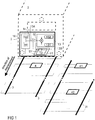
- FIG. 1 shows an on-board device 1 according to the invention mounted on-board a guided vehicle 2 which is configured to follow a route defined by a pair of rails 3.
- a balise 4 is installed on the route or rail track followed by the guided vehicle 2, for example between the rails 3.
- the rail track may comprise several balises 4 forming a system of balises 4, each balise being configured to exchange information with the guided vehicle 2 when the latter passes at proximity, for instance above/over, said balise 4.
- the balise 4 and the on-board device 1 exchange information by means of electromagnetic signals transmitted from the balise 4, respectively on-board device 1, to the on-board device 1, respectively balise 4.
- undesired cross-talk signal might be received from another balise 41 installed on an adjacent route defined by another pair of rails 31 in proximity of the balise 4 or any other component which might generate an electromagnetic field from a signal sent by the on-board device 1 and capable of interfering with the signal received by the on-board device 1 from the balise 4.
- a cross-talk signal emitted by another balise 42 installed on said adjacent route might be received by the on-board device 1 while no balise is installed on the route followed by said guided vehicle 2.
- the on-board device 1 comprises preferentially an emitter 11, a receiver 12, a processing unit 14 and a test component 13.
- the emitter 11 is for instance configured for remotely powering the balise 4 by means of radiant energy, and/or for transmitting an initialization signal to the balise, and/or for storing data within the balise 4.
- the balise is configured for sending an electromagnetic signal, i.e. the so-called telegram, comprising encoded information to the receiver 12 of the on-board device.
- the balise might be a self-powered balise.
- the balise may send an electromagnetic signal to the receiver when the latter is detected, or may send said electromagnetic signal to the receiver in response to its powering by the emitter 11.
- An antenna of the receiver 12 is configured for receiving the electromagnetic signal of the balise and outputting, from its interaction with said electromagnetic signal, a reception signal S1 that is sent to the processing unit 14 in order to determine the information provided by the balise 4.
- Said reception signal S1 is the signal outputted by the antenna of the receiver 12 when said antenna induces a current from its interaction with electromagnetic radiations. If the electromagnetic radiation comes from a balise installed on the route of the guided vehicle, then the reception signal S1 comprises information transmitted by the balise for said guided vehicle.
- said reception signal may comprise information or data that might be wrongly interpreted by the processing unit 14, leading for instance to a wrong positioning of the guided vehicle with respect to the railway network.
- a Frequency-Shift Keying (FSK) technique for transmitting the telegram to the receiver 12.
- FSK Frequency-Shift Keying
- digital information provided by the balise to the receiver 12 is transmitted by means of said telegram through discrete frequencies that encode information: typically in case of binary FSK, a pair of discrete frequencies (see for instance the frequencies F1 and F2 in Figure 3 ) is used for encoding binary information in the form of a succession of 0 and 1 (e.g. one frequency encoding "0" and the other frequency encoding "1").
- This is a known technique which does not need further detailed explanations.
- the reception signal S1 outputted by the antenna of the receiver 12 and resulting from the reception of the telegram is a function of said discrete frequencies, said reception signal S1 being then processed by a FSK demodulator 141 of the processing unit 14 in order to determine the information encoded in the telegram.
- the on-board device 1 further comprises a test component 13 configured for adding to or incorporating into the reception signal S1 which is outputted by the antenna of the receiver 12 in function of the electromagnetic radiation received by the receiver antenna, a test signal S2, for instance added in series 134 to an output of the antenna of the receiver 12 or directly transmitted in the form of a test electromagnetic signal to the receiver antenna so that the reception signal S1 induced in the receiver antenna by electromagnetic radiation comprises said test signal S2.
- the test signal S2 is the signal outputted by the test component 13 and incorporated or added to the reception signal outputted by the antenna of the receiver.
- test signal might refer to different kind of physical signals depending on the stage at which said wording is used: for instance it can refer to output current flowing through an output wire of the test component, and/or to said electromagnetic test signal radiated by the test antenna 133 of the test component 13, said electromagnetic test signal being created for instance by said output current flowing through the output wire of the test component, and/or to the part of the reception signal either coming from current induced by the electromagnetic test signal or from output current directly added to an output of the receiver antenna by the test component. Therefore, the physical nature of the test signal can change depending on the context wherein it is cited. Nevertheless, in each case, the purpose of the test signal S2 is the same, i.e.
- the test signal S2 outputted by the test component 13 is designed for spreading in the whole reception bandwidth of the receiver 12.
- the test signal S2 is a DSSS signal added to the reception signal S1.
- the DSSS signal is created by the test component 13 from a test message 132 modulated by a pseudorandom sequence of bits known by and stored within a memory of the processing unit 14.
- the test message 132 is also stored in a memory of the processing unit 14.
- Said pseudorandom sequence consists in particular in a radio pulse (also called "chip") whose duration is shorter compared to the duration of the test message.
- the chip sequence 131 is multiplied by the test message 132 in order to create the test signal S2.
- the test signal S2 is then centered inside the receiver bandwidth, for instance by modulating a carrier frequency.
- a Differential Phase Shift Keying DPSK
- Said test signal S2 is then added to the reception signal S1.
- the test component 13 comprises a test antenna 133 for emitting a test electromagnetic signal for incorporating or adding the test signal S2 to the reception signal S1, wherein the test electromagnetic signal is configured for being received or picked up by the receiver antenna.
- the test signal S2 is outputted by the test component 13 and directly added to, or incorporated into, the reception signal S1, so that the latter comprises the test signal S2 before being processed by the processing unit 14.
- the processing unit 14 further comprises a test signal demodulator 142 capable of demodulating the reception signal S1 in order to ensure that the on-board device 1 is working properly.
- the test signal demodulator 142 is configured for comparing the test message 132 stored in the memory of the processing unit 14 with the test message 132 extracted from the reception signal S1, wherein a divergence between the stored test message and the extracted test message might be interpreted as a failure of the on-board device 1.
- the test component comprises a modulator, such as a DPSK modulator, for modulating the test signal S2 and providing the latter to the test antenna 133.
- a modulator such as a DPSK modulator
- other techniques for modulating the test signal S2 might be used in order to create a test signal S2 whose frequencies spread within the whole reception bandwidth of the receiver.
- Figure 2 illustrates a schematic view of the steps of the claimed method, comprising
- a variation of amplitude of the test signal S2 is preferentially automatically detected by the processing unit 14 by measuring a correlation between peaks of the chip sequence and peaks of amplitude of the test signal S2 as extracted by the demodulator 142, i.e. as obtained from the demodulation of the reception signal S1 (the extracted test signal will be called hereafter "extracted test signal").
- the chip sequence is used by the processing unit 14 for testing the extracted test signal S2.
- the processing unit 14 uses the chip sequence for generating an autocorrelation function with the extracted test signal S2, wherein said autocorrelation function typically exhibits sharp peaks.
- the autocorrelation function provides a correlation signal wherein a low value correlation signal is obtained when the chip sequence is time shifted in regards to the received test signal, and a high value correlation signal is obtained when the chip sequence and the received test signal are correlated.
- the high value of the correlation signal is proportional to the number of chips and amplitude of the chips.
- the processing unit 14 is preferentially configured for detecting a change of the amplitude of the test signal S2 from changes in values of the correlation signal obtained from said autocorrelation function, wherein a change of the amplitude of the test signal S2 outputted by the test component 13 is automatically detected as a change of the correlation signal value measured by the processing unit 14.
- the processing unit 14 is configured for automatically signaling a failure of the on-board device 1 if the value of the correlation signal is below a predefined threshold, which might be stored in a memory of the processing unit 14.
- a change of the amplitude of the test signal S2 is detected from a change of the amplitude of the correlation signal (i.e. for instance a change of the amplitude value of correlation peaks of the correlation signal).
- the correlation signal might be in particular continuously measured over time by the processing unit 14 in order to continuously check the correct working of the on-board device 1.
- Figure 3 shows a schematic representation of the FSK spectrum of the reception signal S1 outputted by the antenna of the receiver 12 after reception of the electromagnetic signal emitted by the balise and the spread spectrum of the test signal S2 which is added to said reception signal in order to ensure that cross-talk signal cannot be demodulated from the reception signal S1 when the latter comprises the test signal S2.
Landscapes
- Engineering & Computer Science (AREA)
- Mechanical Engineering (AREA)
- Computer Networks & Wireless Communication (AREA)
- Signal Processing (AREA)
- Monitoring And Testing Of Transmission In General (AREA)
- Mobile Radio Communication Systems (AREA)
Description
- The present invention concerns a system and a method for protecting a communication between a balise and a guided vehicle on-board device from cross-talk, wherein balises are installed at points along a route followed by the guided vehicle.
- The present invention is related to the problematic of cross-talk that may occur when an on-board device of a guided vehicle receives a signal (said signal being typically a "telegram") from a balise mounted on a track of a railway network that is followed by the guided vehicle. Cross-talk refers to an undesired effect in the on-board device created by the reception by said on-board device of an additional signal (also called hereafter "cross-talk signal") apart from the signal received from the balise it is reading, i.e. said telegram. Typically, there is cross-talk when a telegram is read from a balise that should not be read, like a balise on another track. The cross-talk signal might be received by an on-board device while no signal is expected, leading for instance to an incorrect localization of the guided vehicle.
- From a general point of view the present invention deals with balises (also called beacons) installed on a route or track followed by the guided vehicle and which are configured for exchanging data with the guided vehicle by means of an electromagnetic signal when the guided vehicle passes near, for example above/over, the balise. In particular, said balise is an Eurobalise, i.e. a balise which complies with the European Train Control System, and is installed between rails of a railway followed by the guided vehicle. "Guided vehicle" according to the present invention refers to public transport means such as buses, trolleybuses, streetcars, subways, trains or train units, etc., as well as load transporting means such as, for example, overhead traveling cranes, for which safety is a very important factor and which are guided along a route or railway for instance by at least one rail, in particular by two rails between which balises are placed.
- In order to solve this problematic of cross-talk, it has been proposed to measure the amplitude of the signal received by the on-board device, and to cut the signal if it becomes under a given threshold. Unfortunately, such a solution requires to regularly check the gain of the on-board device in order to ensure that it did not change, or to use an on-board device comprising redundant independent receiving units for the reading of balise signals. Additionally, this solution requires the threshold being safety guaranteed, which is a complex task.
- The
document GB 2 027 244 A - An objective of the present invention is to propose a new system and method for protecting from cross-talk a communication between a balise and a guided vehicle on-board device, which are simple, efficient, and whose failure might be easily and cost efficiently detected.
- For achieving said objective, the present invention proposes to incorporate into a reception signal outputted by an antenna of a receiver of the on-board device a test signal acting as a noise to limit the sensitivity of the on-board device as disclosed in the objects of
independent claims 1 and 9. Other advantages of the invention are presented in the dependent claims. - The present invention proposes notably an on-board device for reading a telegram of a balise installed at a point along a route followed by a guided vehicle in which said on-board device is designed to be installed, said on-board device comprising:
- optionally an emitter configured for remotely powering the balise, in particular by means of radiant energy. Said emitter comprising for example an antenna comprising an emitting loop for radiating energy, in particular radio frequency energy, the balise being then powered by said radiated energy and able to transmit, in return, an electromagnetic signal that is the so-called telegram;
- a receiver comprising an antenna, the receiver being configured for outputting a reception signal in function of an electromagnetic radiation picked up or received by the antenna. Typically, the antenna of the receiver is configured for picking up the telegram transmitted by the balise, for instance in response to its powering by the emitter, and for delivering the reception signal to a processing unit. In this case, the electromagnetic radiation picked up by the receiver antenna comprises the electromagnetic signal sent by the balise, i.e. said telegram. In particular, the telegram is produced by a transmitting loop of the balise and transmitted by the latter to the receiver through an air gap separating the receiver antenna from the balise transmitting loop. The reception signal results from current induced by the electromagnetic radiation in each receiving loop of the antenna of the receiver, said current providing a measure of the amplitude of the electromagnetic radiation received by the antenna. When said electromagnetic radiation comprises only the electromagnetic signal emitted by the balise, then the amplitude of the electromagnetic signal is typically a function of the position of the receiver antenna compared to the position of the balise;
- a processing unit capable of processing the reception signal outputted by the receiver antenna notably in order to read said telegram, i.e. determine information comprised within the electromagnetic radiation picked up by the antenna;
the on-board device according to the invention being characterized in that it comprises - a test component configured for adding to or incorporating into the reception signal and before its processing by the processing unit a test signal, preferentially a Direct Sequence Spread Spectrum (DSSS) signal, said test signal being configured for acting as a noise for limiting a sensitivity of the receiver. Preferentially, said test component comprises a test antenna configured for transmitting the test signal through the antenna of the receiver of the on-board device. The adding of the test signal to the reception signal makes it impossible to demodulate a cross-talk signal that would be received by the receiver because said test signal is configured for being spread into the whole reception bandwidth of the receiver, and therefore protects the on-board device from any cross-talk undesired effects. Preferentially, the test signal amplitude is limited to a predefined value in order to limit a signal to noise ratio for the reception signal. The test signal according to the invention typically acts as a white noise inside the receiver bandwidth as it is spread in said bandwidth.
- The present invention concerns also a method for protecting from cross-talk an on-board device configured for reading telegrams of balises installed at points along a route followed by a guided vehicle in which said on-board device is installed, the method comprising the following steps:
- optionally remotely powering the balise by means of an emitter of the on-board device, or sending an initialization signal to the balise;
- optionally sending an electromagnetic signal (the so-called telegram) to a receiver of the on-board device, wherein said electromagnetic signal is produced by the balise, for instance in response to its powering by the emitter, or in response to a reception by the balise of the initialization signal sent by the emitter;
- picking up an electromagnetic radiation by means of an antenna of the receiver of the on-board device and outputting a reception signal in function of the picked up electromagnetic radiation to a processing unit, wherein said electromagnetic radiation may comprise the electromagnetic signal emitted by the balise;
- receiving and processing the reception signal by means of the processing unit in order to determine information comprised within said electromagnetic radiation;
the method according to the invention being characterized in that it comprises - adding to or incorporating into the reception signal and before its processing by the processing unit a test signal, preferentially said Direct Sequence Spread Spectrum (DSSS) signal, said test signal acting as a noise for limiting a sensitivity of the receiver, wherein said test signal is configured for spreading over the whole reception bandwidth of the receiver. Preferentially, the test signal is incorporated into the reception signal by emitting a test electromagnetic signal by a test antenna of a test component of the on-board device, said test electromagnetic signal being configured for being directly received or picked up by the receiver antenna.
- According to the present invention, the test signal is a known signal whose characteristics are known and stored within the on-board device in order to enable the latter to extract the test signal from the reception signal for test and verification purposes.
- Further aspects of the present invention will be better understood through the following drawings, wherein like numerals are used for like and corresponding parts:
- Figure 1
- schematic representation of a preferred embodiment of a system according to the invention mounted on board a guided vehicle.
- Figure 2
- schematic representation of a preferred embodiment of the method according to the invention.
- Figure 3
- schematic representations of the DSSS signal and reception signal processed by the processing unit according to the invention.
-
Figure 1 shows an on-board device 1 according to the invention mounted on-board a guidedvehicle 2 which is configured to follow a route defined by a pair ofrails 3. Abalise 4 is installed on the route or rail track followed by the guidedvehicle 2, for example between therails 3. The rail track may compriseseveral balises 4 forming a system ofbalises 4, each balise being configured to exchange information with the guidedvehicle 2 when the latter passes at proximity, for instance above/over, saidbalise 4. Thebalise 4 and the on-board device 1 exchange information by means of electromagnetic signals transmitted from thebalise 4, respectively on-board device 1, to the on-board device 1, respectively balise 4. During communication between thebalise 4 and the on-board device 1 undesired cross-talk signal might be received from anotherbalise 41 installed on an adjacent route defined by another pair ofrails 31 in proximity of thebalise 4 or any other component which might generate an electromagnetic field from a signal sent by the on-board device 1 and capable of interfering with the signal received by the on-board device 1 from thebalise 4. For instance, a cross-talk signal emitted by anotherbalise 42 installed on said adjacent route might be received by the on-board device 1 while no balise is installed on the route followed by said guidedvehicle 2. - The on-
board device 1 according to the invention comprises preferentially anemitter 11, areceiver 12, aprocessing unit 14 and atest component 13. Theemitter 11 is for instance configured for remotely powering thebalise 4 by means of radiant energy, and/or for transmitting an initialization signal to the balise, and/or for storing data within thebalise 4. The balise is configured for sending an electromagnetic signal, i.e. the so-called telegram, comprising encoded information to thereceiver 12 of the on-board device. The balise might be a self-powered balise. The balise may send an electromagnetic signal to the receiver when the latter is detected, or may send said electromagnetic signal to the receiver in response to its powering by theemitter 11. An antenna of thereceiver 12 is configured for receiving the electromagnetic signal of the balise and outputting, from its interaction with said electromagnetic signal, a reception signal S1 that is sent to theprocessing unit 14 in order to determine the information provided by thebalise 4. Said reception signal S1 is the signal outputted by the antenna of thereceiver 12 when said antenna induces a current from its interaction with electromagnetic radiations. If the electromagnetic radiation comes from a balise installed on the route of the guided vehicle, then the reception signal S1 comprises information transmitted by the balise for said guided vehicle. If said electromagnetic radiation comes from another object which is either an object located on the track of the guided vehicle but different from a balise while capable of emitting electromagnetic radiation or a balise located on an adjacent route, likebalise 42, then said reception signal may comprise information or data that might be wrongly interpreted by theprocessing unit 14, leading for instance to a wrong positioning of the guided vehicle with respect to the railway network. -
Balises 4 typically use a Frequency-Shift Keying (FSK) technique for transmitting the telegram to thereceiver 12. According to said FSK technique, digital information provided by the balise to thereceiver 12 is transmitted by means of said telegram through discrete frequencies that encode information: typically in case of binary FSK, a pair of discrete frequencies (see for instance the frequencies F1 and F2 inFigure 3 ) is used for encoding binary information in the form of a succession of 0 and 1 (e.g. one frequency encoding "0" and the other frequency encoding "1"). This is a known technique which does not need further detailed explanations. The reception signal S1 outputted by the antenna of thereceiver 12 and resulting from the reception of the telegram is a function of said discrete frequencies, said reception signal S1 being then processed by aFSK demodulator 141 of theprocessing unit 14 in order to determine the information encoded in the telegram. - The on-
board device 1 according to the invention further comprises atest component 13 configured for adding to or incorporating into the reception signal S1 which is outputted by the antenna of thereceiver 12 in function of the electromagnetic radiation received by the receiver antenna, a test signal S2, for instance added inseries 134 to an output of the antenna of thereceiver 12 or directly transmitted in the form of a test electromagnetic signal to the receiver antenna so that the reception signal S1 induced in the receiver antenna by electromagnetic radiation comprises said test signal S2. According to the present invention, the test signal S2 is the signal outputted by thetest component 13 and incorporated or added to the reception signal outputted by the antenna of the receiver. According to the present invention, the wording "test signal" might refer to different kind of physical signals depending on the stage at which said wording is used: for instance it can refer to output current flowing through an output wire of the test component, and/or to said electromagnetic test signal radiated by thetest antenna 133 of thetest component 13, said electromagnetic test signal being created for instance by said output current flowing through the output wire of the test component, and/or to the part of the reception signal either coming from current induced by the electromagnetic test signal or from output current directly added to an output of the receiver antenna by the test component. Therefore, the physical nature of the test signal can change depending on the context wherein it is cited. Nevertheless, in each case, the purpose of the test signal S2 is the same, i.e. it is a signal configured for acting as a noise in the whole reception bandwidth of thereceiver 12 so as to limit the sensitivity of the on-board device 1. The test signal S2 outputted by thetest component 13 is designed for spreading in the whole reception bandwidth of thereceiver 12. Preferentially, the test signal S2 is a DSSS signal added to the reception signal S1. In particular, the DSSS signal is created by thetest component 13 from atest message 132 modulated by a pseudorandom sequence of bits known by and stored within a memory of theprocessing unit 14. Preferentially, thetest message 132 is also stored in a memory of theprocessing unit 14. Said pseudorandom sequence consists in particular in a radio pulse (also called "chip") whose duration is shorter compared to the duration of the test message. Thechip sequence 131 is multiplied by thetest message 132 in order to create the test signal S2. Preferentially and if necessary, the test signal S2 is then centered inside the receiver bandwidth, for instance by modulating a carrier frequency. For this purpose of "translating" or shifting the test signal frequency into the bandwidth of the receiver antenna so that it becomes centered within the receiver bandwidth frequency, a Differential Phase Shift Keying (DPSK) might be used for modulating the test signal S2. Said test signal S2 is then added to the reception signal S1. According to a first preferred embodiment, thetest component 13 comprises atest antenna 133 for emitting a test electromagnetic signal for incorporating or adding the test signal S2 to the reception signal S1, wherein the test electromagnetic signal is configured for being received or picked up by the receiver antenna. According to another preferred embodiment, the test signal S2 is outputted by thetest component 13 and directly added to, or incorporated into, the reception signal S1, so that the latter comprises the test signal S2 before being processed by theprocessing unit 14. - Preferentially, the
processing unit 14 further comprises atest signal demodulator 142 capable of demodulating the reception signal S1 in order to ensure that the on-board device 1 is working properly. For instance, thetest signal demodulator 142 is configured for comparing thetest message 132 stored in the memory of theprocessing unit 14 with thetest message 132 extracted from the reception signal S1, wherein a divergence between the stored test message and the extracted test message might be interpreted as a failure of the on-board device 1. - Preferentially, the test component comprises a modulator, such as a DPSK modulator, for modulating the test signal S2 and providing the latter to the
test antenna 133. Apart from the DPSK technique, other techniques for modulating the test signal S2 might be used in order to create a test signal S2 whose frequencies spread within the whole reception bandwidth of the receiver. -
Figure 2 illustrates a schematic view of the steps of the claimed method, comprising - optionally, remotely powering 81 the
balise 4 by means of anemitter 11 of the on-board device 1; - optionally, sending 82, by the
balise 4, for instance in response to its powering by theemitter 11, an electromagnetic signal to thereceiver 12 of the on-board device 1, wherein said electromagnetic signal is preferentially a FSK signal encoding information transmitted by thebalise 4; - outputting or generating 83 a test signal S2 by a
test component 13, wherein said test signal S2 acts as a noise for limiting a sensitivity of thereceiver 12, wherein said test signal S2 is configured for spreading over the whole reception bandwidth of thereceiver 12, and wherein said test signal S2 preferentially encodes atest message 132; - adding 84 said test signal S2 to (or incorporating said test signal S2 into) a reception signal S1 outputted by an antenna of the
receiver 12 of the on-board device 1, wherein said adding takes place before the processing of the reception signal S1 by aprocessing unit 14. Preferentially, the test signal S2 is added directly at the output of the receiver antenna or into the antenna. Indeed, according to a preferred embodiment, the test signal S2 is added to the reception signal S1 by means of inductive coupling with the receiver antenna. For instance, thetest component 13 comprises atest antenna 133 for sending a test electromagnetic signal to thereceiver 12 in order to incorporate said test signal S2 to the reception signal S1 outputted by the receiver antenna through inductive coupling. In that case, the test signal S2 is induced directly into the antenna of the receiver by the test electromagnetic signal emitted by thetest antenna 133 and outputted by thetest component 13. The test electromagnetic signal is in particular configured for being picked up by the receiver antenna. Indeed, the antenna of thereceiver 12 is configured for picking up an electromagnetic radiation which comprises the test electromagnetic signal embedding the test signal S2 and optionally the electromagnetic signal emitted by the balise and embedding said telegram, said picking up of electromagnetic radiation resulting in an output of the reception signal S1 induced by the electromagnetic radiation received by the antenna. In that case, the test electromagnetic signal acts as a noise for limiting the sensitivity of thereceiver 12, spreads over the whole reception bandwidth of thereceiver 12, and preferentially encodes thetest message 132. According to another embodiment, the test signal S2 is a current signal directly added, for instance added in series, to the reception signal S1 outputted by the antenna of thereceiver 12, so that the reception signal S1 comprises the test signal S2 before its processing by theprocessing unit 14; - processing 85 by means of the
processing unit 14 the reception signal S1 in order to determine information comprised within the electromagnetic radiation picked up by the receiver antenna, said electromagnetic radiation comprising for instance information sent by thebalise 4 and; - optionally, testing if the on-
board device 1 is working properly from an extraction of the test message from the reception signal S1. - In particular, in order to test the correct working of the on-
board device 1, a variation of amplitude of the test signal S2 is preferentially automatically detected by theprocessing unit 14 by measuring a correlation between peaks of the chip sequence and peaks of amplitude of the test signal S2 as extracted by thedemodulator 142, i.e. as obtained from the demodulation of the reception signal S1 (the extracted test signal will be called hereafter "extracted test signal"). Typically, the chip sequence is used by theprocessing unit 14 for testing the extracted test signal S2. In particular, theprocessing unit 14 uses the chip sequence for generating an autocorrelation function with the extracted test signal S2, wherein said autocorrelation function typically exhibits sharp peaks. In that case, the autocorrelation function provides a correlation signal wherein a low value correlation signal is obtained when the chip sequence is time shifted in regards to the received test signal, and a high value correlation signal is obtained when the chip sequence and the received test signal are correlated. In particular, the high value of the correlation signal is proportional to the number of chips and amplitude of the chips. Theprocessing unit 14 is preferentially configured for detecting a change of the amplitude of the test signal S2 from changes in values of the correlation signal obtained from said autocorrelation function, wherein a change of the amplitude of the test signal S2 outputted by thetest component 13 is automatically detected as a change of the correlation signal value measured by theprocessing unit 14. Preferentially, theprocessing unit 14 is configured for automatically signaling a failure of the on-board device 1 if the value of the correlation signal is below a predefined threshold, which might be stored in a memory of theprocessing unit 14. Typically, a change of the amplitude of the test signal S2 is detected from a change of the amplitude of the correlation signal (i.e. for instance a change of the amplitude value of correlation peaks of the correlation signal). The correlation signal might be in particular continuously measured over time by theprocessing unit 14 in order to continuously check the correct working of the on-board device 1. - Finally,
Figure 3 shows a schematic representation of the FSK spectrum of the reception signal S1 outputted by the antenna of thereceiver 12 after reception of the electromagnetic signal emitted by the balise and the spread spectrum of the test signal S2 which is added to said reception signal in order to ensure that cross-talk signal cannot be demodulated from the reception signal S1 when the latter comprises the test signal S2. - To conclude, the present invention presents the following advantages compared to existing techniques:
- the test signal added to the reception signal can be automatically adjusted by the test component for ensuring an upper limit of the sensitivity of the receiver, by defining for instance a value for a signal to noise ratio that is very difficult to realize using known techniques, such a value being typically 2.4dB. Indeed, FSK demodulation is not possible under a given signal to noise ratio, and therefore injecting in the reception signal a noise, specifically a white noise, of a given and known energy by means of the test signal enables to guarantee a maximal sensitivity of the receiver;
- the test signal acts as a noise added to the reception signal to limit the signal to noise ratio.
- the test message might be used to test a correct working of the on-board device;
- the proposed solution is an intrinsic limitation of the receiver sensitivity which does not require to double any part of the receiver;
- offline tests of the on-board device, which might be performed at each initialization of the on-board device before the guided vehicle is moving on a track equipped with balises and for determining the threshold level of its receiver, can be strongly reduced or even suppressed, since a level of correlation peak gives directly an image of the receiver gain.
Claims (13)
- On-board device (1) for reading a telegram of a balise (4) installed at a point along a route followed by a guided vehicle (2) in which said on-board device (1) is designed to be installed, said on-board device (1) comprising:- a receiver (12) comprising an antenna capable of picking up the telegram transmitted by the balise (4) and configured for delivering a reception signal (S1) to a processing unit (14);- the processing unit (14) configured for processing the reception signal (S1) in order to read the telegram sent by the balise (4);
and being characterized in that it comprises a test component (13) configured for adding to the reception signal (S1) and before its processing by the processing unit (14) a test signal (S2), said test signal being configured for acting as a noise for limiting a sensitivity of the receiver (12). - On-board device (1) according to claim 1, wherein the test signal is added into the antenna of the receiver (12) .
- On-board device (1) according to claim 1 or 2, wherein a Direct Sequence Spread Spectrum (DSSS) technique is used for creating the test signal (S2).
- On-board device (1) according to one of the claims 1-3, wherein the processing unit (14) comprises a test signal demodulator (142) and/or a correlator configured for verifying that the reception signal (S1) comprises the test signal (S2).
- On-board device (1) according to claim 4, wherein the demodulator is configured for detecting a change of the sensitivity of the receiver by measuring an amplitude of correlation peaks.
- On-board device (1) according to one of the claim 1-5, wherein the test signal (S2) is realized by modulating a pseudorandom sequence (131) of bits known by the on-board device by a test message (132).
- On-board device (1) according to claim 6, wherein a correct working of the on-board device is determined through demodulation of the reception signal (S1) by means of the test signal demodulator (142).
- Guided vehicle (2) comprising the on-board device (1) according to one of the claims 1-7.
- Method for protecting from cross-talk an on-board device (1) configured for reading a telegram of a balise (4) installed at a point along a route followed by a guided vehicle (2) in which said on-board device (1) is installed, the method comprising the following steps:- receiving an electromagnetic radiation by means of an antenna of a receiver (12) of the on-board device;- outputting, by means of said receiver (12), a reception signal (S1) in response to the reception of said electromagnetic radiation;- receiving and processing the reception signal (S1) by means of a processing unit (14) in order to determine information comprised within said electromagnetic radiation;
the method according to the invention being characterized in that it comprises- adding to the reception signal (S1) and before its processing by the processing unit (14) a test signal (S2), wherein said test signal (S2) is configured for acting as a noise for limiting a sensitivity of the receiver (12). - Method according to claim 9, wherein the electromagnetic radiation comprises an electromagnetic test signal emitted by a test antenna (133) of a test component (13) of the on-board device (1) for inducing said test signal (S2) in the antenna of the receiver (12).
- Method according to claim 9 or 10, wherein a Direct Sequence Spread Spectrum (DSSS) technique is used for creating the test signal (S2).
- Method according to one of the claims 9-11, wherein the test signal (S2) is obtained by modulating, by a test message (132), a pseudorandom sequence (131) of bits known by the on-board device (1).
- Method according to one of the claims 9-12, comprising determining a correct working of the on-board device (1) via demodulation of the reception signal (S1) by means of a test signal demodulator (142).
Priority Applications (6)
| Application Number | Priority Date | Filing Date | Title |
|---|---|---|---|
| HUE17290146A HUE050120T2 (en) | 2017-11-09 | 2017-11-09 | System and method for protecting a communication between a balise and a guided vehicle from cross-talk |
| EP17290146.4A EP3483032B1 (en) | 2017-11-09 | 2017-11-09 | System and method for protecting a communication between a balise and a guided vehicle from cross-talk |
| ES17290146T ES2813562T3 (en) | 2017-11-09 | 2017-11-09 | System and procedure to protect a communication between a beacon and a guided vehicle against crosstalk |
| BR112020009042-5A BR112020009042B1 (en) | 2017-11-09 | 2018-10-04 | ON-BOARD DEVICE FOR READING A TELEGRAM FROM AN ELECTRONIC HEADLIGHT, GUIDED VEHICLE AND METHOD FOR PROTECTING AGAINST CROSSWORD AN ON-BOARD DEVICE CONFIGURED TO READ A TELEGRAM FROM AN ELECTRONIC HEADLIGHT |
| US16/763,025 US11479279B2 (en) | 2017-11-09 | 2018-10-04 | System and method for protecting a communication between a balise and a guided vehicle from cross-talk |
| PCT/EP2018/077013 WO2019091673A1 (en) | 2017-11-09 | 2018-10-04 | System and method for protecting a communication between a balise and a guided vehicle from cross-talk |
Applications Claiming Priority (1)
| Application Number | Priority Date | Filing Date | Title |
|---|---|---|---|
| EP17290146.4A EP3483032B1 (en) | 2017-11-09 | 2017-11-09 | System and method for protecting a communication between a balise and a guided vehicle from cross-talk |
Publications (2)
| Publication Number | Publication Date |
|---|---|
| EP3483032A1 EP3483032A1 (en) | 2019-05-15 |
| EP3483032B1 true EP3483032B1 (en) | 2020-05-27 |
Family
ID=60452562
Family Applications (1)
| Application Number | Title | Priority Date | Filing Date |
|---|---|---|---|
| EP17290146.4A Active EP3483032B1 (en) | 2017-11-09 | 2017-11-09 | System and method for protecting a communication between a balise and a guided vehicle from cross-talk |
Country Status (5)
| Country | Link |
|---|---|
| US (1) | US11479279B2 (en) |
| EP (1) | EP3483032B1 (en) |
| ES (1) | ES2813562T3 (en) |
| HU (1) | HUE050120T2 (en) |
| WO (1) | WO2019091673A1 (en) |
Families Citing this family (3)
| Publication number | Priority date | Publication date | Assignee | Title |
|---|---|---|---|---|
| CN112389506A (en) * | 2019-08-14 | 2021-02-23 | 比亚迪股份有限公司 | Train signal system and linkage method thereof |
| CN111422219B (en) * | 2020-04-30 | 2022-02-18 | 北京和利时系统工程有限公司 | Main lobe message identification method and device |
| CN113517937B (en) * | 2021-07-15 | 2023-10-24 | 北京铁路信号有限公司 | Test method and system |
Family Cites Families (6)
| Publication number | Priority date | Publication date | Assignee | Title |
|---|---|---|---|---|
| FR2434069A1 (en) * | 1978-07-27 | 1980-03-21 | Silec Liaisons Elec | SIGNALING DEVICE FOR GUIDED VEHICLES |
| US9425854B2 (en) * | 2012-06-18 | 2016-08-23 | Alstom Transport Technologies | Spread spectrum signals in vehicle network systems |
| DE102013220868A1 (en) * | 2013-10-15 | 2015-04-30 | Siemens Aktiengesellschaft | Eurobalise vehicle device and method of operating a Eurobalier vehicle device |
| US9606224B2 (en) * | 2014-01-14 | 2017-03-28 | Alstom Transport Technologies | Systems and methods for vehicle position detection |
| DE102014212516A1 (en) * | 2014-06-27 | 2015-12-31 | Siemens Aktiengesellschaft | Checking the authenticity of a balise |
| DE102016217190A1 (en) * | 2016-09-09 | 2018-03-15 | Siemens Aktiengesellschaft | A method of communicating information from a trackside device to a vehicle and means for performing such a method |
-
2017
- 2017-11-09 ES ES17290146T patent/ES2813562T3/en active Active
- 2017-11-09 HU HUE17290146A patent/HUE050120T2/en unknown
- 2017-11-09 EP EP17290146.4A patent/EP3483032B1/en active Active
-
2018
- 2018-10-04 WO PCT/EP2018/077013 patent/WO2019091673A1/en active Application Filing
- 2018-10-04 US US16/763,025 patent/US11479279B2/en active Active
Non-Patent Citations (1)
| Title |
|---|
| None * |
Also Published As
| Publication number | Publication date |
|---|---|
| US20200385035A1 (en) | 2020-12-10 |
| EP3483032A1 (en) | 2019-05-15 |
| HUE050120T2 (en) | 2020-11-30 |
| US11479279B2 (en) | 2022-10-25 |
| BR112020009042A2 (en) | 2020-11-03 |
| ES2813562T3 (en) | 2021-03-24 |
| WO2019091673A1 (en) | 2019-05-16 |
Similar Documents
| Publication | Publication Date | Title |
|---|---|---|
| US11479279B2 (en) | System and method for protecting a communication between a balise and a guided vehicle from cross-talk | |
| EP2676860B1 (en) | Methods and Systems for Signal Fingerprinting | |
| CN106585667B (en) | A kind of System and method for for vehicle-mounted beacon antenna fault detection | |
| KR20140044830A (en) | Location of a transponder center point | |
| WO2016012106A1 (en) | System and method for locating the center of a beacon equipping guided vehicle routes | |
| AU2015224435B2 (en) | Device for confirming the integrity of a coupling of a rail vehicle and associated rail vehicle | |
| US20140124628A1 (en) | Railway circuit for sending signalling information along a railway line to a vehicle travelling along the railway line | |
| JP2002048862A (en) | Detecting device for movement direction of moving body | |
| AU2021232733B2 (en) | Vehicle-based device for receiving information from a track-based transmission device | |
| KR101431285B1 (en) | Detection system and method for railway track circuits using bpsk modulated coding | |
| EP2985629B1 (en) | System and method for detecting and locating the center of beacons installed along guided vehicle routes | |
| EP2328790B1 (en) | Method and apparatus for determining the occupation state of the circuit of a direct current track circuit in a railway line | |
| BR112020009042B1 (en) | ON-BOARD DEVICE FOR READING A TELEGRAM FROM AN ELECTRONIC HEADLIGHT, GUIDED VEHICLE AND METHOD FOR PROTECTING AGAINST CROSSWORD AN ON-BOARD DEVICE CONFIGURED TO READ A TELEGRAM FROM AN ELECTRONIC HEADLIGHT | |
| EP2022697A1 (en) | Communication system for vehicles particularly railway vehicles or the like and stationary units | |
| KR102088471B1 (en) | Train control device | |
| JP4785938B2 (en) | Ground / vehicle information transmission apparatus and ground / vehicle information transmission method | |
| JP2007196858A (en) | Scanning type digital train detecting device | |
| JP3544517B2 (en) | Train position detection device | |
| JP2012081906A (en) | Automatic train control device | |
| JP2011088556A (en) | Information transmission device between ground and vehicle |
Legal Events
| Date | Code | Title | Description |
|---|---|---|---|
| PUAI | Public reference made under article 153(3) epc to a published international application that has entered the european phase |
Free format text: ORIGINAL CODE: 0009012 |
|
| STAA | Information on the status of an ep patent application or granted ep patent |
Free format text: STATUS: THE APPLICATION HAS BEEN PUBLISHED |
|
| AK | Designated contracting states |
Kind code of ref document: A1 Designated state(s): AL AT BE BG CH CY CZ DE DK EE ES FI FR GB GR HR HU IE IS IT LI LT LU LV MC MK MT NL NO PL PT RO RS SE SI SK SM TR |
|
| AX | Request for extension of the european patent |
Extension state: BA ME |
|
| STAA | Information on the status of an ep patent application or granted ep patent |
Free format text: STATUS: REQUEST FOR EXAMINATION WAS MADE |
|
| RAP1 | Party data changed (applicant data changed or rights of an application transferred) |
Owner name: SIEMENS MOBILITY S.A.S. |
|
| 17P | Request for examination filed |
Effective date: 20190919 |
|
| RBV | Designated contracting states (corrected) |
Designated state(s): AL AT BE BG CH CY CZ DE DK EE ES FI FR GB GR HR HU IE IS IT LI LT LU LV MC MK MT NL NO PL PT RO RS SE SI SK SM TR |
|
| GRAP | Despatch of communication of intention to grant a patent |
Free format text: ORIGINAL CODE: EPIDOSNIGR1 |
|
| STAA | Information on the status of an ep patent application or granted ep patent |
Free format text: STATUS: GRANT OF PATENT IS INTENDED |
|
| INTG | Intention to grant announced |
Effective date: 20200220 |
|
| GRAS | Grant fee paid |
Free format text: ORIGINAL CODE: EPIDOSNIGR3 |
|
| GRAA | (expected) grant |
Free format text: ORIGINAL CODE: 0009210 |
|
| STAA | Information on the status of an ep patent application or granted ep patent |
Free format text: STATUS: THE PATENT HAS BEEN GRANTED |
|
| AK | Designated contracting states |
Kind code of ref document: B1 Designated state(s): AL AT BE BG CH CY CZ DE DK EE ES FI FR GB GR HR HU IE IS IT LI LT LU LV MC MK MT NL NO PL PT RO RS SE SI SK SM TR |
|
| REG | Reference to a national code |
Ref country code: GB Ref legal event code: FG4D |
|
| REG | Reference to a national code |
Ref country code: CH Ref legal event code: EP |
|
| REG | Reference to a national code |
Ref country code: AT Ref legal event code: REF Ref document number: 1274270 Country of ref document: AT Kind code of ref document: T Effective date: 20200615 |
|
| REG | Reference to a national code |
Ref country code: DE Ref legal event code: R096 Ref document number: 602017017249 Country of ref document: DE |
|
| REG | Reference to a national code |
Ref country code: FI Ref legal event code: FGE |
|
| REG | Reference to a national code |
Ref country code: LT Ref legal event code: MG4D |
|
| PG25 | Lapsed in a contracting state [announced via postgrant information from national office to epo] |
Ref country code: LT Free format text: LAPSE BECAUSE OF FAILURE TO SUBMIT A TRANSLATION OF THE DESCRIPTION OR TO PAY THE FEE WITHIN THE PRESCRIBED TIME-LIMIT Effective date: 20200527 Ref country code: PT Free format text: LAPSE BECAUSE OF FAILURE TO SUBMIT A TRANSLATION OF THE DESCRIPTION OR TO PAY THE FEE WITHIN THE PRESCRIBED TIME-LIMIT Effective date: 20200928 Ref country code: SE Free format text: LAPSE BECAUSE OF FAILURE TO SUBMIT A TRANSLATION OF THE DESCRIPTION OR TO PAY THE FEE WITHIN THE PRESCRIBED TIME-LIMIT Effective date: 20200527 Ref country code: IS Free format text: LAPSE BECAUSE OF FAILURE TO SUBMIT A TRANSLATION OF THE DESCRIPTION OR TO PAY THE FEE WITHIN THE PRESCRIBED TIME-LIMIT Effective date: 20200927 Ref country code: NO Free format text: LAPSE BECAUSE OF FAILURE TO SUBMIT A TRANSLATION OF THE DESCRIPTION OR TO PAY THE FEE WITHIN THE PRESCRIBED TIME-LIMIT Effective date: 20200827 Ref country code: GR Free format text: LAPSE BECAUSE OF FAILURE TO SUBMIT A TRANSLATION OF THE DESCRIPTION OR TO PAY THE FEE WITHIN THE PRESCRIBED TIME-LIMIT Effective date: 20200828 |
|
| REG | Reference to a national code |
Ref country code: NL Ref legal event code: MP Effective date: 20200527 |
|
| PG25 | Lapsed in a contracting state [announced via postgrant information from national office to epo] |
Ref country code: HR Free format text: LAPSE BECAUSE OF FAILURE TO SUBMIT A TRANSLATION OF THE DESCRIPTION OR TO PAY THE FEE WITHIN THE PRESCRIBED TIME-LIMIT Effective date: 20200527 Ref country code: RS Free format text: LAPSE BECAUSE OF FAILURE TO SUBMIT A TRANSLATION OF THE DESCRIPTION OR TO PAY THE FEE WITHIN THE PRESCRIBED TIME-LIMIT Effective date: 20200527 Ref country code: BG Free format text: LAPSE BECAUSE OF FAILURE TO SUBMIT A TRANSLATION OF THE DESCRIPTION OR TO PAY THE FEE WITHIN THE PRESCRIBED TIME-LIMIT Effective date: 20200827 Ref country code: LV Free format text: LAPSE BECAUSE OF FAILURE TO SUBMIT A TRANSLATION OF THE DESCRIPTION OR TO PAY THE FEE WITHIN THE PRESCRIBED TIME-LIMIT Effective date: 20200527 |
|
| REG | Reference to a national code |
Ref country code: HU Ref legal event code: AG4A Ref document number: E050120 Country of ref document: HU |
|
| REG | Reference to a national code |
Ref country code: AT Ref legal event code: MK05 Ref document number: 1274270 Country of ref document: AT Kind code of ref document: T Effective date: 20200527 |
|
| PG25 | Lapsed in a contracting state [announced via postgrant information from national office to epo] |
Ref country code: AL Free format text: LAPSE BECAUSE OF FAILURE TO SUBMIT A TRANSLATION OF THE DESCRIPTION OR TO PAY THE FEE WITHIN THE PRESCRIBED TIME-LIMIT Effective date: 20200527 Ref country code: NL Free format text: LAPSE BECAUSE OF FAILURE TO SUBMIT A TRANSLATION OF THE DESCRIPTION OR TO PAY THE FEE WITHIN THE PRESCRIBED TIME-LIMIT Effective date: 20200527 |
|
| PG25 | Lapsed in a contracting state [announced via postgrant information from national office to epo] |
Ref country code: IT Free format text: LAPSE BECAUSE OF FAILURE TO SUBMIT A TRANSLATION OF THE DESCRIPTION OR TO PAY THE FEE WITHIN THE PRESCRIBED TIME-LIMIT Effective date: 20200527 Ref country code: CZ Free format text: LAPSE BECAUSE OF FAILURE TO SUBMIT A TRANSLATION OF THE DESCRIPTION OR TO PAY THE FEE WITHIN THE PRESCRIBED TIME-LIMIT Effective date: 20200527 Ref country code: RO Free format text: LAPSE BECAUSE OF FAILURE TO SUBMIT A TRANSLATION OF THE DESCRIPTION OR TO PAY THE FEE WITHIN THE PRESCRIBED TIME-LIMIT Effective date: 20200527 Ref country code: EE Free format text: LAPSE BECAUSE OF FAILURE TO SUBMIT A TRANSLATION OF THE DESCRIPTION OR TO PAY THE FEE WITHIN THE PRESCRIBED TIME-LIMIT Effective date: 20200527 Ref country code: SM Free format text: LAPSE BECAUSE OF FAILURE TO SUBMIT A TRANSLATION OF THE DESCRIPTION OR TO PAY THE FEE WITHIN THE PRESCRIBED TIME-LIMIT Effective date: 20200527 Ref country code: AT Free format text: LAPSE BECAUSE OF FAILURE TO SUBMIT A TRANSLATION OF THE DESCRIPTION OR TO PAY THE FEE WITHIN THE PRESCRIBED TIME-LIMIT Effective date: 20200527 Ref country code: DK Free format text: LAPSE BECAUSE OF FAILURE TO SUBMIT A TRANSLATION OF THE DESCRIPTION OR TO PAY THE FEE WITHIN THE PRESCRIBED TIME-LIMIT Effective date: 20200527 |
|
| PG25 | Lapsed in a contracting state [announced via postgrant information from national office to epo] |
Ref country code: SK Free format text: LAPSE BECAUSE OF FAILURE TO SUBMIT A TRANSLATION OF THE DESCRIPTION OR TO PAY THE FEE WITHIN THE PRESCRIBED TIME-LIMIT Effective date: 20200527 Ref country code: PL Free format text: LAPSE BECAUSE OF FAILURE TO SUBMIT A TRANSLATION OF THE DESCRIPTION OR TO PAY THE FEE WITHIN THE PRESCRIBED TIME-LIMIT Effective date: 20200527 |
|
| REG | Reference to a national code |
Ref country code: DE Ref legal event code: R097 Ref document number: 602017017249 Country of ref document: DE |
|
| REG | Reference to a national code |
Ref country code: ES Ref legal event code: FG2A Ref document number: 2813562 Country of ref document: ES Kind code of ref document: T3 Effective date: 20210324 |
|
| PLBE | No opposition filed within time limit |
Free format text: ORIGINAL CODE: 0009261 |
|
| STAA | Information on the status of an ep patent application or granted ep patent |
Free format text: STATUS: NO OPPOSITION FILED WITHIN TIME LIMIT |
|
| REG | Reference to a national code |
Ref country code: CH Ref legal event code: NV Representative=s name: SIEMENS SCHWEIZ AG, CH |
|
| 26N | No opposition filed |
Effective date: 20210302 |
|
| PG25 | Lapsed in a contracting state [announced via postgrant information from national office to epo] |
Ref country code: SI Free format text: LAPSE BECAUSE OF FAILURE TO SUBMIT A TRANSLATION OF THE DESCRIPTION OR TO PAY THE FEE WITHIN THE PRESCRIBED TIME-LIMIT Effective date: 20200527 |
|
| REG | Reference to a national code |
Ref country code: DE Ref legal event code: R119 Ref document number: 602017017249 Country of ref document: DE |
|
| PG25 | Lapsed in a contracting state [announced via postgrant information from national office to epo] |
Ref country code: MC Free format text: LAPSE BECAUSE OF FAILURE TO SUBMIT A TRANSLATION OF THE DESCRIPTION OR TO PAY THE FEE WITHIN THE PRESCRIBED TIME-LIMIT Effective date: 20200527 |
|
| REG | Reference to a national code |
Ref country code: CH Ref legal event code: PL |
|
| PG25 | Lapsed in a contracting state [announced via postgrant information from national office to epo] |
Ref country code: LU Free format text: LAPSE BECAUSE OF NON-PAYMENT OF DUE FEES Effective date: 20201109 |
|
| REG | Reference to a national code |
Ref country code: BE Ref legal event code: MM Effective date: 20201130 |
|
| PG25 | Lapsed in a contracting state [announced via postgrant information from national office to epo] |
Ref country code: CH Free format text: LAPSE BECAUSE OF NON-PAYMENT OF DUE FEES Effective date: 20201130 Ref country code: LI Free format text: LAPSE BECAUSE OF NON-PAYMENT OF DUE FEES Effective date: 20201130 |
|
| PG25 | Lapsed in a contracting state [announced via postgrant information from national office to epo] |
Ref country code: IE Free format text: LAPSE BECAUSE OF NON-PAYMENT OF DUE FEES Effective date: 20201109 |
|
| PG25 | Lapsed in a contracting state [announced via postgrant information from national office to epo] |
Ref country code: DE Free format text: LAPSE BECAUSE OF NON-PAYMENT OF DUE FEES Effective date: 20210601 |
|
| PG25 | Lapsed in a contracting state [announced via postgrant information from national office to epo] |
Ref country code: TR Free format text: LAPSE BECAUSE OF FAILURE TO SUBMIT A TRANSLATION OF THE DESCRIPTION OR TO PAY THE FEE WITHIN THE PRESCRIBED TIME-LIMIT Effective date: 20200527 Ref country code: MT Free format text: LAPSE BECAUSE OF FAILURE TO SUBMIT A TRANSLATION OF THE DESCRIPTION OR TO PAY THE FEE WITHIN THE PRESCRIBED TIME-LIMIT Effective date: 20200527 Ref country code: CY Free format text: LAPSE BECAUSE OF FAILURE TO SUBMIT A TRANSLATION OF THE DESCRIPTION OR TO PAY THE FEE WITHIN THE PRESCRIBED TIME-LIMIT Effective date: 20200527 |
|
| PG25 | Lapsed in a contracting state [announced via postgrant information from national office to epo] |
Ref country code: MK Free format text: LAPSE BECAUSE OF FAILURE TO SUBMIT A TRANSLATION OF THE DESCRIPTION OR TO PAY THE FEE WITHIN THE PRESCRIBED TIME-LIMIT Effective date: 20200527 |
|
| GBPC | Gb: european patent ceased through non-payment of renewal fee |
Effective date: 20211109 |
|
| PG25 | Lapsed in a contracting state [announced via postgrant information from national office to epo] |
Ref country code: BE Free format text: LAPSE BECAUSE OF NON-PAYMENT OF DUE FEES Effective date: 20201130 |
|
| PG25 | Lapsed in a contracting state [announced via postgrant information from national office to epo] |
Ref country code: GB Free format text: LAPSE BECAUSE OF NON-PAYMENT OF DUE FEES Effective date: 20211109 |
|
| PGFP | Annual fee paid to national office [announced via postgrant information from national office to epo] |
Ref country code: FR Payment date: 20231114 Year of fee payment: 7 Ref country code: FI Payment date: 20231121 Year of fee payment: 7 |
|
| PGFP | Annual fee paid to national office [announced via postgrant information from national office to epo] |
Ref country code: ES Payment date: 20240221 Year of fee payment: 7 |
|
| PGFP | Annual fee paid to national office [announced via postgrant information from national office to epo] |
Ref country code: HU Payment date: 20240123 Year of fee payment: 7 |