EP3482480B1 - Befestigungsanordnung eines elektromotors und sitz - Google Patents
Befestigungsanordnung eines elektromotors und sitz Download PDFInfo
- Publication number
- EP3482480B1 EP3482480B1 EP17735524.5A EP17735524A EP3482480B1 EP 3482480 B1 EP3482480 B1 EP 3482480B1 EP 17735524 A EP17735524 A EP 17735524A EP 3482480 B1 EP3482480 B1 EP 3482480B1
- Authority
- EP
- European Patent Office
- Prior art keywords
- motor
- electric motor
- locking element
- seat
- fixing element
- Prior art date
- Legal status (The legal status is an assumption and is not a legal conclusion. Google has not performed a legal analysis and makes no representation as to the accuracy of the status listed.)
- Active
Links
Images




Classifications
-
- H—ELECTRICITY
- H02—GENERATION; CONVERSION OR DISTRIBUTION OF ELECTRIC POWER
- H02K—DYNAMO-ELECTRIC MACHINES
- H02K5/00—Casings; Enclosures; Supports
- H02K5/26—Means for adjusting casings relative to their supports
-
- B—PERFORMING OPERATIONS; TRANSPORTING
- B60—VEHICLES IN GENERAL
- B60N—SEATS SPECIALLY ADAPTED FOR VEHICLES; VEHICLE PASSENGER ACCOMMODATION NOT OTHERWISE PROVIDED FOR
- B60N2/00—Seats specially adapted for vehicles; Arrangement or mounting of seats in vehicles
- B60N2/02—Seats specially adapted for vehicles; Arrangement or mounting of seats in vehicles the seat or part thereof being movable, e.g. adjustable
- B60N2/0224—Non-manual adjustments, e.g. with electrical operation
- B60N2/02246—Electric motors therefor
-
- B—PERFORMING OPERATIONS; TRANSPORTING
- B60—VEHICLES IN GENERAL
- B60N—SEATS SPECIALLY ADAPTED FOR VEHICLES; VEHICLE PASSENGER ACCOMMODATION NOT OTHERWISE PROVIDED FOR
- B60N2/00—Seats specially adapted for vehicles; Arrangement or mounting of seats in vehicles
- B60N2/02—Seats specially adapted for vehicles; Arrangement or mounting of seats in vehicles the seat or part thereof being movable, e.g. adjustable
- B60N2/0224—Non-manual adjustments, e.g. with electrical operation
- B60N2/02246—Electric motors therefor
- B60N2/02258—Electric motors therefor characterised by the mounting of the electric motor for adjusting the seat
-
- B—PERFORMING OPERATIONS; TRANSPORTING
- B60—VEHICLES IN GENERAL
- B60N—SEATS SPECIALLY ADAPTED FOR VEHICLES; VEHICLE PASSENGER ACCOMMODATION NOT OTHERWISE PROVIDED FOR
- B60N2/00—Seats specially adapted for vehicles; Arrangement or mounting of seats in vehicles
- B60N2/02—Seats specially adapted for vehicles; Arrangement or mounting of seats in vehicles the seat or part thereof being movable, e.g. adjustable
- B60N2/04—Seats specially adapted for vehicles; Arrangement or mounting of seats in vehicles the seat or part thereof being movable, e.g. adjustable the whole seat being movable
- B60N2/06—Seats specially adapted for vehicles; Arrangement or mounting of seats in vehicles the seat or part thereof being movable, e.g. adjustable the whole seat being movable slidable
- B60N2/067—Seats specially adapted for vehicles; Arrangement or mounting of seats in vehicles the seat or part thereof being movable, e.g. adjustable the whole seat being movable slidable by linear actuators, e.g. linear screw mechanisms
Definitions
- the invention relates to an electric motor with a fastening arrangement, in particular for fastening the electric motor to a seat.
- the invention further relates to a seat with such an electric motor.
- Seats are adjustable in length, height and inclination.
- the position of the seat can be adjusted manually, for example using a lever and/or a handle, or electrically using an electric motor, which can be actuated via a control element.
- the electric motor can be attached to the seat using a specific attachment arrangement.
- the fastening arrangement for fixing the electric motor includes fastening tabs on the electric motor, which correspond to fastening pins on the seat.
- An adjustable motor mount which has two interlocking base plates and two upwardly curved brackets which can be arranged on axially projecting, end-side bell hub sections of a motor.
- the interlocking base plates are slidably disposed relative to one another and can be axially adjusted to accommodate motors with different axial lengths.
- GB 2 033 672 A discloses an electrical machine with a housing which has a housing shell and a bearing plate attached to at least one end of the housing shell.
- the housing also has a swivel arm, which is part of the housing shell, and a stiffening arm, which is a component of the end shield.
- the electrical machine further comprises a stator arranged in the housing shell and a rotor mounted in the end shield.
- US 2001/048058 A1 discloses a motor-driven adjustment device for a vehicle seat.
- the adjusting device comprises a motor with a housing which has two protruding end pieces and a support to which the housing of the motor is attached.
- the two end pieces of the housing are accommodated in viscoelastic sleeves, which are each arranged elastically in holders, the holders being designed to support the housing against rotation.
- Other vehicle seats with an electric motor adjustment mechanism are, for example, in FR 2 883 810 A1 and US 2013/015313 A1 disclosed.
- the invention is based on the object of specifying an improved electric motor compared to the prior art with a fastening arrangement, in particular for fastening the electric motor to a seat, and an improved seat with such an electric motor.
- the object is achieved according to the invention with the features specified in claim 1.
- the object is achieved according to the invention with the features specified in claim 7.
- An electric motor according to the invention with a fastening arrangement in particular for fastening the electric motor to a seat, comprises at least one motor fixing element and at least one motor locking element, which are each arranged on the electric motor.
- the at least one motor fixing element is designed such that the electric motor can be moved into a rotational position, in particular pre-positioned or pre-fixed.
- the at least one motor locking element is designed in such a way that the electric motor can be locked in a set rotational position, the motor locking element being designed such that the electric motor can be immovably fixed in the axial direction and can be secured against rotation by means of a torque lock, the at least one motor locking element having a polygonal profile , wherein the outer profile of the motor locking element has a plurality of surfaces evenly distributed over the circumference, which form the shape of a polygon, the motor fixing element extending in the axial direction outwards from the motor locking element and the motor fixing element enabling a plug connection of the electric motor and the outer profile of the motor locking element Torque lock forms.
- the at least one motor fixing element and the motor locking element are arranged on an end face of the electric motor.
- the at least one motor fixing element and the motor locking element are arranged coaxially to one another.
- the motor fixing element and the motor locking element are arranged coaxially to a motor axis of the electric motor, the motor fixing element being surrounded by the motor locking element in the radial direction outwards and being arranged coaxially therewith.
- the motor locking element and the at least one motor fixing element can, for example, be arranged axially offset from one another.
- the motor fixing element extends in the axial direction outwards from the motor locking element. The motor fixing element thus enables a plug connection of the electric motor and the motor locking element enables a torque lock of the electric motor.
- the motor locking element is preferably designed in such a way that the electric motor is fixed in an immovable manner in the axial direction and secured against rotation by means of a torque lock.
- the outer profile of the motor locking element has a plurality of surfaces in the form of a polygon that are evenly distributed over the circumference and thus forms a torque lock.
- the motor fixing element is preferably designed in such a way that the electric motor is fixed in an immovable manner in the axial direction and can be adjusted into one of several rotational positions, in particular in stages.
- the at least one motor locking element is designed as a formation arranged on the front side of the electric motor and projecting axially from a bearing plate of an electric motor housing.
- the motor locking element can be formed in one piece with the end shield.
- the motor locking element can also be designed as a separate component that is connected to the end shield, e.g. B. by means of material connection.
- the end shield forms a front end of the electric motor housing and is therefore to be understood as a type of housing cover, with the end shield either representing a separate component or being formed in one piece with the electric motor housing, for example by means of deep drawing.
- the electric motor housing is usually provided with two bearing shields, so that the electric motor housing is each provided with a bearing shield on the front side.
- the motor locking element has the polygonal profile and can be connected to the corresponding locking component on the seat.
- the polygonal profile has at least four functional surfaces, ideally six or more functional surfaces, so that the polygonal profile can be designed, for example, as an outer hexagonal profile, octagonal profile or decagonal profile.
- the electric motor and thus the electrical connection can be arranged in six different rotational positions relative to the seat, with the rotational positions each being offset from one another at an angle of 60° with respect to a rotation axis of the electric motor are.
- the corresponding locking component is designed as a recess in the seat, which has a polygonal profile, in particular an inner polygonal profile, corresponding to the polygonal profile of the at least one motor locking element.
- the motor locking element can thus be arranged in the locking component in a form-fitting manner, in particular with a precise fit, and in a locking manner due to the polygonal profile. A rotation of the electric motor housing is no longer possible, so that a torque lock of the electric motor is possible without additional fasteners.
- two motor fixing elements are provided, by means of which the electric motor can be fixed to the seat.
- the electric motor can be fixed to the seat by means of a motor fixing element arranged on an output side of the electric motor via a positive and frictional connection, in particular via a clamp connection.
- the corresponding fixing component includes, for example, a clamping opening.
- the electric motor can be fixed to the seat via a positive connection.
- the seat includes a corresponding recess in which the motor fixing element can be arranged in a form-fitting manner.
- the motor locking element and the motor fixing element are thus arranged at a common front end of the electric motor, but are arranged on different cutting planes through a rotation axis of the electric motor.
- the motor fixing elements are each guided axially outwards by means of a bearing plate projecting bearing journal of the electric motor is formed, the bearing journals each being arranged coaxially to the axis of rotation of the electric motor.
- the invention further relates to a seat with an electric motor and a fastening arrangement according to the previous description, wherein the fastening arrangement comprises at least one motor fixing element and at least one motor locking element, the at least one motor fixing element being designed such that the electric motor can be moved into a rotational position, and the at least one Motor locking element is designed such that the electric motor can be locked in a set rotational position, wherein the motor locking element is designed such that the electric motor is fixed non-displaceably in the axial direction and secured against rotation by means of a torque lock, wherein the at least one motor locking element has a polygonal profile, wherein the Outer profile of the motor locking element has several surfaces evenly distributed over the circumference, which form the shape of a polygon.
- the fastening arrangement comprises at least one motor fixing element and at least one motor locking element, the at least one motor fixing element being designed such that the electric motor can be moved into a rotational position, and the at least one Motor locking element is designed such that the electric motor can be locked in a set rotational position
- the fastening arrangement comprises at least one fixing component corresponding to the motor fixing element and at least one locking component corresponding to the motor locking element, wherein the fixing component and the locking component are each arranged on the seat, and wherein the electric motor is controlled by means of the at least one motor locking element and the at least one corresponding locking component with respect to a rotational position of the Electric motor can be flexibly arranged relative to the seat and locked in the set rotation position.
- the electric motor can be fixed to the seat via a positive or frictional connection by means of a motor fixing element arranged on an output side of the electric motor.
- the electric motor can also be fixed to the seat via a positive connection by means of a motor fixing element arranged on another output side of the electric motor.
- the fastening arrangement is particularly suitable for a longitudinal adjuster of a seat, wherein according to an exemplary embodiment the at least one fixing component and the at least one locking component are arranged on a support element of a longitudinal adjuster unit of the seat.
- Figure 1 shows a top view of a support element 1 of a longitudinal adjuster unit L (see Figure 15 ) one in Figure 16 shown seat S, for example a vehicle seat, with an electric motor 2 and a fastening arrangement B for the electric motor 2 according to the prior art.
- Figure 2 shows a perspective detail with the support element 1 and the electric motor 2 and the fastening arrangement B according to the prior art.
- Figure 3 shows a perspective detail with the support element 1 and the electric motor 2 according to Figures 1 and 2 in the disconnected state.
- the carrier element 1 is made, for example, of plastic and has a seat part, in particular with an upper rail 3 connected to the seat part (see Figure 15 ), connected, by means of which the seat part is mounted along a lower rail 5 (see.) attached to a vehicle floor Figure 15 ) can be moved longitudinally.
- an electric motor 2 is assigned to both upper rails 3 of the seat S, which drives the upper rails 3 and can be moved longitudinally relative to the lower rail 5.
- Gears can be provided in a known manner to transmit motor drive movements of the electric motor 2 to the upper rails 3.
- Two shafts 4.1, 4.2 are shown as an example, which are connected to the electric motor 2 and to a spindle (not shown), the spindles being connected to the upper rails 3. That is, the electric motor 2 transmits torque via rotatable shafts 4.1, 4.2 to gear units (not shown in detail) arranged in the upper rails 3. These then transmit the torque via spindles in a movement in a longitudinal direction of the rail.
- the electric motor 2 is, for example, a direct current motor and includes a rotatably mounted rotor (not shown) which rotates about a motor axis M.
- the rotor is surrounded by a stator, also not shown.
- the rotor and the stator are arranged in a common electric motor housing 2.1.
- a front end of the electric motor housing 2.1 is formed by a bearing shield 2.1.1, 2.1.2 in the form of a housing cover, whereby the bearing shields 2.1.1, 2.1.2 can each represent a separate component that is connected to the electric motor housing 2.1.
- one of the end shields 2.1.1, 2.1.2 can be connected in one piece to the electric motor housing 2.1, for example by deep drawing.
- a bearing pin 2.2.1, 2.2.2 is arranged at one front end of the electric motor housing 2.1, which is arranged coaxially to the motor axis M of the rotor.
- the bearing journals 2.2.1, 2.2.2 each protrude axially outwards through the corresponding bearing plate 2.1.1, 2.1.2.
- the electrical connection 2.3 is designed as a plug, which is connected, in particular latched, to an outer circumference of the electric motor housing 2.1.
- the electrical connection 2.3 can be connected by means of certain connection components to an on-board electrical system of a vehicle in which the seat S is arranged.
- the electric motor 2 To arrange and fasten the electric motor 2 in the carrier element 1, it includes two flanges 2.4, each of which is provided with a through opening. Via the flanges 2.4, the electric motor 2 can be connected to connecting elements 1.1, which are arranged in a wall of the carrier element 1 delimiting a receiving opening 1.2.
- the connecting elements 1.1 are, for example, connecting pins that are passed through the through openings of the flanges 2.4 and then fixed.
- the installation position of the electric motor 2 is fixed with respect to its rotational position D relative to the carrier element 1, so that a position of the electrical connection 2.3 relative to the carrier element 1 is also fixed.
- the fastening arrangement B has two motor fixing elements F1, F2 and a motor locking element A, which are arranged on the electric motor 2 and which are located on different cutting planes through the motor axis M of the electric motor 2.
- the motor locking element A is formed in one piece with the end shield 2.1.2 or is connected to it.
- the motor locking element A is designed as a formation A1 and has a polygonal profile P.
- the polygonal profile P is designed as a hexagonal profile which projects axially outwards from the end shield 2.1.2.
- the polygonal profile P can also project radially inwards and/or be designed as an octagonal or decagonal profile.
- the motor fixing elements F1, F2 are formed by the bearing pins 2.2.1, 2.2.2, by means of which the electric motor 2 can be fixed to the support element 1 on both sides.
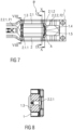
- Figure 7 shows a section with the electric motor 2 according to the description from the Figures 4 to 6 and with the carrier element 1 in a top view in one embodiment.
- the Figures 8 to 10 show sectional views, especially cross sections, through different levels of the in Figure 7 shown section.
- Figure 11 shows a complete view of the electric motor 2 and the support element 1 in top view.
- the electric motor 2 is arranged in the receiving opening 1.2 of the carrier element 1, the receiving opening 1.2 being opposite to the one in the due to the missing flanges 2.4 on the electric motor 2 Figures 1 to 3 shown receiving opening 1.2 is designed with reduced dimensions.
- the electric motor 2 is connected to the carrier element 1 in a frictional and positive manner.
- the fastening arrangement B comprises corresponding fixing components 1.3, 1.4, which are arranged on the support element 1, with one fixing component 1.3 having a clamping opening for the frictional reception of the bearing pin 2.2.1 and the other fixing component 1.4 as an opening for the positive reception of the other bearing pin 2.2. 2 is trained.
- the electric motor 2 in particular the electric motor housing 2.1, is locked in a specific rotational position D relative to the carrier element 1.
- the motor locking element A interacts with a corresponding locking component 1.5, which is in Figure 14 is shown as an example.
- the locking component 1.5 has a polygonal profile 1.5.1 corresponding to the polygonal profile P of the motor locking element A, which is designed as a recess 1.5.1.1.
- the corresponding polygonal profile 1.5.1 can also protrude outwards, with the polygonal profile P of the motor locking element A protruding inwards.
- the locking component 1.5 can thus be formed cost-effectively as a counterpart in the receiving opening 1.2, with no undercuts being necessary in the carrier element 1 during production.
- the carrier element 1 can be produced, for example, using a simple injection molding tool.
- the motor locking element A and the locking component 1.5 thus form a positive, precisely fitting connection in the assembled state of the electric motor 2, with several precisely fitting connections being possible.
- several rotational positions D of the electrical connection 2.3 of the electric motor 2 relative to the carrier element 1 are possible by means of the motor locking element A, with a rotational gradation of the rotational position D of the electrical connection 2.3 in the installed position of the electric motor 2 being a maximum of 60°.
- a finer gradation of less than 60° is preferably possible.
- the electric motor 2 and thus the electrical connection 2.3 can be arranged in six different rotational positions D relative to the carrier element 1, the rotational positions D with respect to the motor axis M of the electric motor 2 each being in are offset from each other at an angle of 60°.
- the motor locking element A forms a precisely fitting connection with the locking component 1.5, the motor locking element A serves in particular as a torque lock to compensate for a supporting torque of the electric motor 2 during a so-called block travel.
- Block travel occurs when the top rail 3 assigned to the electric motor 2 reaches a mechanical stop.
- the electric motor 2 it can be pre-fixed to the carrier element 1 in a first step by means of the motor fixing element F2, with the bearing pin 2.2.2 being arranged in a form-fitting manner in the fixing component 1.4.
- a desired rotational position D of the electric motor 2 is selected relative to the carrier element 1 and the electric motor 2 with the motor locking element A is arranged accordingly in the locking component 1.5.
- the motor fixing element F2 is simultaneously placed in the Fixing component 1.4 arranged.
- This first step shows Figure 12 in a perspective view.
- Figure 14 shows a perspective detail with the support element 1 and the electric motor 2 in the disconnected state, with the locking component 1.5 being shown in more detail.
- Figure 15 shows in perspective the longitudinal adjustment unit L with the support element 1, the electric motor 2 and two upper rails 3 of the seat S.
- Figure 16 shows a seat S with a longitudinal adjustment unit L in a simplified representation.
Landscapes
- Engineering & Computer Science (AREA)
- Aviation & Aerospace Engineering (AREA)
- Transportation (AREA)
- Mechanical Engineering (AREA)
- Power Engineering (AREA)
- Motor Or Generator Frames (AREA)
- Seats For Vehicles (AREA)
Description
- Die Erfindung betrifft einen Elektromotor mit einer Befestigungsanordnung, insbesondere zur Befestigung des Elektromotors an einem Sitz. Die Erfindung betrifft weiterhin einen Sitz mit einem solchen Elektromotor.
- Sitze, insbesondere Fahrzeugsitze, sind längs-, höhen- und neigungsverstellbar. Die Verstellung einer Position des Sitzes kann manuell beispielsweise mittels eines Hebels und/oder eines Griffs oder elektrisch mittels eines Elektromotors erfolgen, welcher über ein Bedienelement betätigbar ist. Mittels einer bestimmten Befestigungsanordnung kann der Elektromotor am Sitz befestigt werden. Beispielsweise umfasst die Befestigungsanordnung zur Fixierung des Elektromotors Befestigungslaschen am Elektromotor, die mit Befestigungsstiften am Sitz korrespondieren.
- Aus
DE 20 2008 005 744 U1 sind ein Elektromotor und ein Bürstenträger bekannt. Der Bürstenträger weist sechs im Wesentlichen röhrenförmige Schraubenöffnungen auf. - In
US 3 983 429 A ist ein eine einstellbare Motorhalterung offenbart, die zwei ineinandergreifende Grundplatten sowie zwei nach oben gebogene Bügel aufweist, die an axial vorstehenden, endseitigen Glockennabenabschnitten eines Motors anordenbar sind. Die ineinandergreifenden Grundplatten sind verschiebbar zueinander angeordnet und können axial eingestellt werden, um Motoren mit unterschiedlichen axialen Längen aufzunehmen. -
GB 2 033 672 A - Des Weiteren ist aus
US 2001/048058 A1 eine motorisch angetriebene Verstellvorrichtung für einen Fahrzeugsitz offenbart. Die Verstellvorrichtung umfasst einen Motor mit einem Gehäuse, welches zwei überstehende Endstücke und eine Auflage aufweist, an der das Gehäuse des Motors befestigt ist. Die beiden Endstücke des Gehäuses sind in viskoelastischen Hülsen aufgenommen, die jeweils elastisch in Halterungen angeordnet sind, wobei die Halterungen zur Abstützung des Gehäuses gegen Rotation ausgebildet sind. Weitere Fahrzeugsitze mit einem elektromotorischen Verstellmechanismus werden beispielsweise inFR 2 883 810 A1 US 2013/015313 A1 offenbart. - Der Erfindung liegt die Aufgabe zu Grunde, einen gegenüber dem Stand der Technik verbesserten Elektromotor mit einer Befestigungsanordnung, insbesondere zur Befestigung des Elektromotors an einem Sitz, sowie einen verbesserten Sitz mit einem solchen Elektromotor anzugeben.
- Hinsichtlich des Elektromotors mit einer Befestigungsanordnung wird die Aufgabe erfindungsgemäß mit den in Anspruch 1 angegebenen Merkmalen gelöst. Hinsichtlich des Sitzes wird die Aufgabe erfindungsgemäß mit den in Anspruch 7 angegebenen Merkmalen gelöst.
- Vorteilhafte Ausgestaltungen der Erfindung sind Gegenstand der Unteransprüche.
- Ein erfindungsgemäßer Elektromotor mit einer Befestigungsanordnung, insbesondere zur Befestigung des Elektromotors an einem Sitz, umfasst mindestens ein Motorfixierelement und mindestens ein Motorarretierelement, die jeweils am Elektromotor angeordnet sind. Das mindestens eine Motorfixierelement ist derart ausgebildet, dass der Elektromotor in eine Drehposition stellbar, insbesondere vorpositionier- oder vorfixierbar, ist. Das mindestens eine Motorarretierelement ist derart ausgebildet, dass der Elektromotor in einer eingestellten Drehposition arretierbar ist, wobei das Motorarretierelement derart ausgebildet ist, dass der Elektromotor in axialer Richtung unverschiebbar festlegbar und mittels einer Drehmomentsperre gegen Verdrehung sicherbar ist, wobei das mindestens eine Motorarretierelement ein Polygonalprofil aufweist, wobei das Außenprofil des Motorarretierelements mehrere über den Umfang gleichmäßig verteilte Flächen aufweist, die die Form eines Polygons bilden, wobei sich das Motorfixierelement in axialer Richtung nach außen ausgehend vom Motorarretierelement erstreckt und wobei das Motorfixierelement eine Steckverbindung des Elektromotors ermöglicht und das Außenprofil des Motorarretierelements die Drehmomentsperre bildet.
- Mittels der derart ausgebildeten Befestigungsanordnung ist eine flexible Anordnung des Elektromotors relativ zum Sitz möglich, wobei gleichzeitig eine Drehmomentsperre mit einem verringerten Bauraumbedarf ermöglicht wird. Dadurch, dass der Elektromotor in verschiedenen Drehpositionen relativ zum Sitz befestigbar ist, kann eine Position eines elektrischen Anschlusses des Elektromotors im Bauraum des Sitzes flexibel gewählt werden. Dies ermöglicht eine Verwendung von Elektromotoren mit einer weitestgehend einheitlichen Position des elektrischen Anschlusses am Umfang des Elektromotors.
- Gemäß einem Ausführungsbeispiel sind das mindestens eine Motorfixierelement und das Motorarretierelement an einer Stirnseite des Elektromotors angeordnet.
- Bevorzugt sind das mindestens eine Motorfixierelement und das Motorarretierelement koaxial zueinander angeordnet. Insbesondere sind das Motorfixierelement und das Motorarretierelement koaxial zu einer Motorachse des Elektromotors angeordnet, wobei das Motorfixierelement vom Motorarretierelement in radialer Richtung nach außen umgeben wird und koaxial zu diesem angeordnet ist.
- Ferner können das Motorarretierelement und das mindestens eine Motorfixierelement beispielsweise axial versetzt zueinander angeordnet sein. Insbesondere erstreckt sich das Motorfixierelement in axialer Richtung nach außen ausgehend vom Motorarretierelement. Das Motorfixierelement ermöglicht somit eine Steckverbindung des Elektromotors und das Motorarretierelement eine Drehmomentsperre des Elektromotors.
- Darüber hinaus ist das Motorarretierelement bevorzugt derart ausgebildet, dass der Elektromotor in axialer Richtung unverschiebbar festgelegt und mittels einer Drehmomentsperre gegen Verdrehung gesichert ist.
- Das Außenprofil des Motorarretierelements weist erfindungsgemäß mehrere über den Umfang gleichmäßig verteilte Flächen in Form eines Polygons auf und bildet damit eine Drehmomentsperre.
- Weiterhin ist das Motorfixierelement bevorzugt derart ausgebildet, dass der Elektromotor in axialer Richtung unverschiebbar festgelegt und in eine von mehreren Drehpositionen, insbesondere gestuft stellbar ist.
- Gemäß einem Ausführungsbeispiel ist das mindestens eine Motorarretierelement als eine stirnseitig am Elektromotor angeordnete und axial von einem Lagerschild eines Elektromotorgehäuses abragende Ausformung ausgebildet. Das Motorarretierelement kann dabei einteilig mit dem Lagerschild ausgebildet sein. Alternativ kann das Motorarretierelement auch als eine separate Komponente ausgebildet sein, die mit dem Lagerschild verbunden ist, z. B. mittels Stoffschluss. Das Lagerschild bildet ein stirnseitiges Ende des Elektromotorgehäuses und ist somit als eine Art Gehäusedeckel zu verstehen, wobei das Lagerschild entweder eine separate Komponente darstellt oder einteilig mit dem Elektromotorgehäuse ausgebildet ist, beispielsweise mittels Tiefziehen. Üblicherweise ist das Elektromotorgehäuse mit zwei Lagerschilden versehen, so dass das Elektromotorgehäuse jeweils stirnseitig mit einem Lagerschild versehen ist.
- Das Motorarretierelement weist erfindungsgemäß das Polygonalprofil auf und ist mit der korrespondierenden Arretierkomponente am Sitz verbindbar. Insbesondere weist das Polygonalprofil mindestens vier Funktionsflächen, idealerweise sechs oder mehr Funktionsflächen auf, so dass das Polygonalprofil beispielsweise als ein äußeres Hexagonalprofil, Oktagonalprofil oder Dekagonalprofil ausgebildet sein kann. Mittels des Polygonalprofils sind mehrere Drehpositionen des Elektromotors und somit eines elektrischen Anschlusses des Elektromotors relativ zum Sitz möglich, wobei eine rotatorische Stufung der Drehposition des elektrischen Anschlusses in Einbaulage des Elektromotors vorzugweise maximal 60° beträgt. D. h., im konkreten Fall eines hexagonalen Profils des Motorarretierelements kann der Elektromotor und damit der elektrische Anschluss in sechs verschiedenen Drehpositionen relativ zum Sitz angeordnet werden, wobei die Drehpositionen in Bezug auf eine Rotationsachse des Elektromotors jeweils in einem Winkel von 60° zueinander versetzt sind.
- Beispielsweise ist die korrespondierende Arretierkomponente als eine Aussparung im Sitz ausgebildet, die ein mit dem Polygonalprofil des mindestens einen Motorarretierelements korrespondierendes Polygonalprofil, insbesondere ein inneres Polygonalprofil, aufweist. Damit ist das Motorarretierelement in der Arretierkomponente formschlüssig, insbesondere passgenau, und aufgrund des Polygonalprofils arretierend anordenbar. Eine Drehung des Elektromotorgehäuses ist damit nicht mehr möglich, so dass eine Drehmomentsperre des Elektromotors ohne zusätzliche Befestigungselemente möglich ist.
- Gemäß einem weiteren Ausführungsbeispiel sind zwei Motorfixierelemente vorgesehen, mittels denen der Elektromotor am Sitz fixierbar ist.
- Beispielsweise ist der Elektromotor mittels eines an einer Abtriebsseite des Elektromotors angeordneten Motorfixierelements über eine form- und reibschlüssige Verbindung, insbesondere über eine Klemmverbindung, am Sitz fixierbar. Die korrespondierende Fixierkomponente umfasst dazu beispielsweise eine Klemmöffnung.
- Mittels des anderen Motorfixierelements, welches auf einer anderen Abtriebsseite des Elektromotors angeordnet ist, ist der Elektromotor über eine formschlüssige Verbindung am Sitz fixierbar. Beispielsweise umfasst der Sitz dazu eine korrespondierende Aussparung, in welcher das Motorfixierelement formschlüssig anordenbar ist. Das Motorarretierelement und das Motorfixierelement sind somit an einem gemeinsamen stirnseitigen Ende des Elektromotors angeordnet, sind jedoch auf verschiedenen Schnittebenen durch eine Rotationsachse des Elektromotors angeordnet.
- Gemäß einem Ausführungsbeispiel sind die Motorfixierelemente jeweils mittels eines durch ein Lagerschild hindurchgeführten, axial nach außen ragenden Lagerzapfens des Elektromotors gebildet, wobei die Lagerzapfen jeweils koaxial zur Rotationsachse des Elektromotors angeordnet sind.
- Die Erfindung betrifft weiterhin einen Sitz mit einem Elektromotor und einer Befestigungsanordnung nach vorheriger Beschreibung, wobei die Befestigungsanordnung mindestens ein Motorfixierelement und mindestens ein Motorarretierelement umfasst, wobei das mindestens eine Motorfixierelement derart ausgebildet ist, dass der Elektromotor in eine Drehposition stellbar ist, und das mindestens eine Motorarretierelement derart ausgebildet ist, dass der Elektromotor in einer eingestellten Drehposition arretierbar ist, wobei das Motorarretierelement derart ausgebildet ist, dass der Elektromotor in axialer Richtung unverschiebbar festgelegt und mittels einer Drehmomentsperre gegen Verdrehung gesichert ist, wobei das mindestens eine Motorarretierelement ein Polygonalprofil aufweist, wobei das Außenprofil des Motorarretierelements mehrere über den Umfang gleichmäßig verteilte Flächen aufweist, die die Form eines Polygons bilden.
- Des Weiteren umfasst die Befestigungsanordnung mindestens eine zum Motorfixierelement korrespondierende Fixierkomponente und mindestens eine zum Motorarretierelement korrespondierende Arretierkomponente, wobei die Fixierkomponente und die Arretierkomponente jeweils am Sitz angeordnet sind, und wobei der Elektromotor mittels des mindestens einen Motorarretierelements und der mindestens einen korrespondierenden Arretierkomponente hinsichtlich einer Drehposition des Elektromotors flexibel relativ zum Sitz anordenbar und in der eingestellten Drehposition arretierbar ist.
- Gemäß einem Ausführungsbeispiel ist der Elektromotor mittels eines an einer Abtriebsseite des Elektromotors angeordneten Motorfixierelements über eine form- oder reibschlüssige Verbindung am Sitz fixierbar.
- Des Weiteren ist der Elektromotor zusätzlich mittels eines an einer anderen Abtriebsseite des Elektromotors angeordneten Motorfixierelements über eine formschlüssige Verbindung am Sitz fixierbar.
- Die Befestigungsanordnung eignet sich insbesondere für einen Längsversteller eines Sitzes, wobei gemäß einem Ausführungsbeispiel die mindestens eine Fixierkomponente und die mindestens eine Arretierkomponente an einem Trägerelement einer Längsverstellereinheit des Sitzes angeordnet sind.
- Ausführungsbeispiele der Erfindung werden anhand von Zeichnungen näher erläutert. Dabei zeigen:
- Figur 1
- schematisch eine Draufsicht auf ein Trägerelement einer Längsverstellereinheit eines Sitzes mit einem Elektromotor im verbundenen Zustand gemäß dem Stand der Technik,
- Figur 2
- schematische eine perspektivische Ansicht eines Ausschnitts mit dem Trägerelement und dem Elektromotor im verbundenen Zustand gemäß dem Stand der Technik,
- Figur 3
- schematisch eine perspektivische Ansicht eines Ausschnitts mit dem Trägerelement und dem Elektromotor gemäß
Figur 1 und 2 im nicht verbundenen Zustand, - Figur 4
- schematisch eine perspektivische Einzelansicht eines Ausführungsbeispiels eines Elektromotors mit einem ein Polygonalprofil aufweisendes Motorarretierelement,
- Figur 5
- schematisch eine Vorderansicht des Elektromotors mit dem Polygonalprofil,
- Figur 6
- schematisch eine weitere perspektivische Einzelansicht des Elektromotors,
- Figur 7
- schematisch eine Draufsicht auf einen Ausschnitt mit einem Trägerelement und dem Elektromotor im verbundenen Zustand,
- Figuren 8 bis 10
- schematisch Schnittdarstellungen des Ausschnitts gemäß
Figur 7 , - Figur 11
- schematisch eine Schnittdarstellung des Trägerelements und des Elektromotors im verbundenen Zustand,
- Figur 12
- schematisch eine perspektivische Ansicht des Trägerelements und des Elektromotors während einer Montage,
- Figur 13
- schematisch eine perspektivische Ansicht des Trägerelements und des Elektromotors nach der Montage,
- Figur 14
- schematisch eine perspektivische Ansicht eines Ausschnitts mit dem Trägerelement und dem Elektromotor im nicht verbundenen Zustand,
- Figur 15
- schematisch eine perspektivische Ansicht einer Längsverstellereinheit mit dem Trägerelement, dem Elektromotor und einer Oberschiene eines Sitzes und
- Figur 16
- schematisch ein Sitz mit einer Längsverstellereinheit.
- Einander entsprechende Teile sind in allen Figuren mit den gleichen Bezugszeichen versehen.
-
Figur 1 zeigt in Draufsicht ein Trägerelement 1 einer Längsverstellereinheit L (sieheFigur 15 ) eines inFigur 16 dargestellten Sitzes S, beispielsweise eines Fahrzeugsitzes, mit einem Elektromotor 2 und eine Befestigungsanordnung B für den Elektromotor 2 gemäß dem Stand der Technik.Figur 2 zeigt perspektivisch einen Ausschnitt mit dem Trägerelement 1 und dem Elektromotor 2 und der Befestigungsanordnung B gemäß dem Stand der Technik.Figur 3 zeigt perspektivisch einen Ausschnitt mit dem Trägerelement 1 und dem Elektromotor 2 gemäßFigur 1 und 2 im nicht verbundenen Zustand. - Das Trägerelement 1 ist beispielsweise aus Kunststoff gefertigt und mit einem Sitzteil, insbesondere mit einer mit dem Sitzteil verbundenen Oberschiene 3 (siehe
Figur 15 ), verbunden, mittels der das Sitzteil entlang einer an einem Fahrzeugboden befestigten Unterschiene 5 (sieheFigur 15 ) längsverschiebbar ist. - Zur Ausführung der Längsbewegung ist beispielsweise beiden Oberschienen 3 des Sitzes S ein Elektromotor 2 zugeordnet, welcher die Oberschienen 3 antreibt und relativ zur Unterschiene 5 längs bewegbar ist. Zur Übertragung motorischer Antriebsbewegungen des Elektromotors 2 auf die Oberschienen 3 können in bekannter Weise Getriebe vorgesehen sein. In den
Figuren 1 bis 3 sind dazu beispielhaft zwei Wellen 4.1, 4.2 dargestellt, die mit dem Elektromotor 2 und mit einer nicht näher dargestellten Spindel verbunden sind, wobei die Spindeln mit den Oberschienen 3 verbunden sind. D. h., der Elektromotor 2 überträgt ein Drehmoment über drehbare Wellen 4.1, 4.2 zu in den Oberschienen 3 angeordneten Getriebeeinheiten (nicht näher dargestellt). Diese übertragen anschließend das Drehmoment über Spindeln in eine Bewegung in eine Schienenlängsrichtung. - Der Elektromotor 2 ist beispielsweise ein Gleichstrommotor und umfasst einen drehbar gelagerten Rotor (nicht näher dargestellt), welcher sich um eine Motorachse M dreht. Der Rotor wird von einem ebenfalls nicht dargestellten Stator umgeben. Der Rotor und der Stator sind in einem gemeinsamen Elektromotorgehäuse 2.1 angeordnet. Ein jeweils stirnseitiges Ende des Elektromotorgehäuses 2.1 wird von einem Lagerschild 2.1.1, 2.1.2 in Form eines Gehäusedeckels gebildet, wobei die Lagerschilde 2.1.1, 2.1.2 jeweils eine separate Komponente darstellen können, die mit dem Elektromotorgehäuses 2.1 verbunden wird. Alternativ kann auch eines der Lagerschilde 2.1.1, 2.1.2 einteilig mit dem Elektromotorgehäuse 2.1 verbunden sein, beispielsweise mittels Tiefziehen. Des Weiteren ist an jeweils einem stirnseitigen Ende des Elektromotorgehäuses 2.1 ein Lagerzapfen 2.2.1, 2.2.2 angeordnet, welcher koaxial zur Motorachse M des Rotors angeordnet ist. Die Lagerzapfen 2.2.1, 2.2.2 ragen jeweils durch das entsprechende Lagerschild 2.1.1, 2.1.2 hindurch axial nach außen.
- Zur elektrischen Energieversorgung des Elektromotors 2 ist dieser mit einem elektrischen Anschluss 2.3 versehen. Der elektrische Anschluss 2.3 ist hierbei als Stecker ausgebildet, welcher mit einem äußeren Umfang des Elektromotorgehäuses 2.1 verbunden, insbesondere verrastet, ist. Der elektrische Anschluss 2.3 ist mittels bestimmter Verbindungskomponenten mit einem Bordnetz eines Fahrzeugs verbindbar, in welchem der Sitz S angeordnet ist.
- Zur Anordnung und Befestigung des Elektromotors 2 im Trägerelement 1 umfasst dieser zwei Flansche 2.4, die jeweils mit einer Durchgangsöffnung versehen sind. Über die Flansche 2.4 kann der Elektromotor 2 mit Verbindungselementen 1.1 verbunden werden, die in einer eine Aufnahmeöffnung 1.2 begrenzenden Wand des Trägerelements 1 angeordnet sind. Die Verbindungselemente 1.1 sind beispielsweise Verbindungsstifte, die durch die Durchgangsöffnungen der Flansche 2.4 hindurch geführt und anschließend fixiert werden.
- Aufgrund der Flansche 2.4, die vom Lagerschild 2.1.2 des stirnseitigen Endes des Elektromotorgehäuses 2.1 radial nach außen abragen, ist ein Durchmesser des Elektromotors 2 in diesem Bereich vergrößert, so dass dazu korrespondierende Abmessungen der Aufnahmeöffnung 1.2 im Trägerelement 1 erforderlich sind.
- Des Weiteren ist die Einbaulage des Elektromotors 2 bezüglich seiner Drehposition D relativ zum Trägerelement 1 fest vorgegeben, so dass eine Lage des elektrischen Anschlusses 2.3 relativ zum Trägerelement 1 ebenfalls fest vorgegeben ist.
- Zur flexiblen Nutzung eines Bauraums für den Elektromotor 2 zumindest hinsichtlich dessen Drehposition D relativ zum Trägerelement 1 wird eine Befestigungsanordnung B' vorgeschlagen, die im Folgenden näher beschrieben wird.
- Dazu zeigen die
Figuren 4 bis 6 jeweils eine Einzelansicht eines Ausführungsbeispiels eines Elektromotors 2. - Die Befestigungsanordnung B' weist zwei Motorfixierelemente F1, F2 und ein Motorarretierelement A auf, welche am Elektromotor 2 angeordnet sind und die sich auf unterschiedlichen Schnittebenen durch die Motorachse M des Elektromotors 2 befinden. Das Motorarretierelement A ist einteilig mit dem Lagerschild 2.1.2 ausgebildet oder mit diesem verbunden. Das Motorarretierelement A ist dabei als eine Ausformung A1 ausgebildet und weist ein Polygonalprofil P auf. Gemäß dem vorliegenden Ausführungsbeispiel ist das Polygonalprofil P als ein Hexagonalprofil ausgebildet, welches axial nach außen vom Lagerschild 2.1.2 abragt. Alternativ kann das Polygonalprofil P auch radial nach innen ragen und/oder als ein Oktagonal- oder Dekagonalprofil ausgebildet sein.
- Die Motorfixierelemente F1, F2 werden von den Lagerzapfen 2.2.1, 2.2.2 gebildet, mittels denen der Elektromotor 2 beidseitig am Trägerelement 1 fixierbar ist.
-
Figur 7 zeigt einen Ausschnitt mit dem Elektromotor 2 gemäß der Beschreibung aus denFiguren 4 bis 6 und mit dem Trägerelement 1 in einem Ausführungsbeispiel in Draufsicht. DieFiguren 8 bis 10 zeigen dazu Schnittdarstellungen, insbesondere Querschnitte, durch verschiedene Ebenen des inFigur 7 gezeigten Ausschnitts.Figur 11 zeigt eine vollständige Ansicht des Elektromotors 2 und des Trägerelements 1 in Draufsicht. - Der Elektromotor 2 ist in der Aufnahmeöffnung 1.2 des Trägerelements 1 angeordnet, wobei die Aufnahmeöffnung 1.2 aufgrund der fehlenden Flansche 2.4 am Elektromotor 2 mit gegenüber der in den
Figuren 1 bis 3 gezeigten Aufnahmeöffnung 1.2 verringerten Abmessungen ausgebildet ist. - Mittels der Motorfixierelemente F1, F2 ist der Elektromotor 2 mit dem Trägerelement 1 reibschlüssig und formschlüssig verbunden. Dazu umfasst die Befestigungsanordnung B' korrespondierende Fixierkomponenten 1.3, 1.4, die am Trägerelement 1 angeordnet sind, wobei eine Fixierkomponente 1.3 eine Klemmöffnung zur reibschlüssigen Aufnahme des Lagerzapfens 2.2.1 aufweist und die andere Fixierkomponente 1.4 als eine Öffnung zur formschlüssigen Aufnahme des anderen Lagerzapfens 2.2.2 ausgebildet ist.
- Mittels des Motorarretierelements A wird der Elektromotor 2, insbesondere das Elektromotorgehäuse 2.1, in einer bestimmten Drehposition D relativ zum Trägerelement 1 arretiert. Das Motorarretierelement A wirkt dabei mit einer korrespondierenden Arretierkomponente 1.5 zusammen, die in
Figur 14 beispielhaft dargestellt ist. Hierbei weist die Arretierkomponente 1.5 ein mit einem zum Polygonalprofil P des Motorarretierelements A korrespondierenden Polygonalprofil 1.5.1 auf, welches als Aussparung 1.5.1.1 ausgebildet ist. Alternativ kann das korrespondierende Polygonalprofil 1.5.1 auch nach außen ragen, wobei das Polygonalprofil P des Motorarretierelements A nach innen ragt. Die Arretierkomponente 1.5 kann somit kosteneffektiv als ein Gegenstück in der Aufnahmeöffnung 1.2 ausgebildet werden, wobei im Trägerelement 1 bei der Herstellung keine Hinterschnitte notwendig sind. Das Trägerelement 1 kann beispielsweise mittels eines einfachen Spritzgusswerkzeugs hergestellt werden. - Das Motorarretierelement A und die Arretierkomponente 1.5 bilden im montierten Zustand des Elektromotors 2 somit eine formschlüssige, passgenaue Verbindung, wobei mehrere passgenaue Verbindungen möglich sind. Daraus resultierend sind mittels des Motorarretierelements A mehrere Drehpositionen D des elektrischen Anschlusses 2.3 des Elektromotors 2 relativ zum Trägerelement 1 möglich, wobei eine rotatorische Stufung der Drehposition D des elektrischen Anschlusses 2.3 in Einbaulage des Elektromotors 2 maximal 60° beträgt. Vorzugsweise ist eine feinere Abstufung mit weniger als 60° möglich. D. h., im konkreten Fall eines Hexagonalprofils des Motorarretierelements A kann der Elektromotor 2 und damit der elektrische Anschluss 2.3 in sechs verschiedenen Drehpositionen D relativ zum Trägerelement 1 angeordnet werden, wobei die Drehpositionen D in Bezug auf die Motorachse M des Elektromotors 2 jeweils in einem Winkel von 60° zueinander versetzt sind.
- Dadurch, dass das Motorarretierelement A mit der Arretierkomponente 1.5 eine passgenaue Verbindung eingeht, dient das Motorarretierelement A insbesondere als eine Drehmomentsperre zur Kompensation eines Abstützmoments des Elektromotors 2 bei einer so genannten Blockfahrt. Eine Blockfahrt tritt hierbei auf, wenn die dem Elektromotor 2 zugeordnete Oberschiene 3 einen mechanischen Anschlag erreicht.
- Zur Montage des Elektromotors 2 kann dieser in einem ersten Schritt mittels des Motorfixierelements F2 am Trägerelement 1 vorfixiert werden, wobei der Lagerzapfen 2.2.2 in der Fixierkomponente 1.4 formschlüssig angeordnet wird. Vor der Vorfixierung des Elektromotors 2 wird eine gewünschte Drehposition D des Elektromotors 2 relativ zum Trägerelement 1 gewählt und der Elektromotor 2 mit dem Motorarretierelement A entsprechend in der Arretierkomponente 1.5 angeordnet. Beim Anordnen des Motorarretierelements A in der Arretierkomponente 1.5 wird gleichzeitig das Motorfixierelement F2 in der Fixierkomponente 1.4 angeordnet. Diesen ersten Schritt zeigt
Figur 12 in einer perspektivischen Darstellung. - In einem zweiten Schritt, welcher perspektivisch in
Figur 13 gezeigt ist, erfolgt eine endgültige Fixierung des Elektromotors 2, wobei der Lagerzapfen 2.2.1 in die Klemmöffnung der Fixierkomponente 1.3 gedrückt wird, so dass das Motorfixierelement F1 und die Fixierkomponente 1.3 reibschlüssig miteinander verbunden sind. -
Figur 14 zeigt perspektivisch einen Ausschnitt mit dem Trägerelement 1 und dem Elektromotor 2 im nicht verbundenen Zustand, wobei die Arretierkomponente 1.5 näher dargestellt ist. -
Figur 15 zeigt perspektivisch die Längsverstellereinheit L mit dem Trägerelement 1, dem Elektromotor 2 und zwei Oberschienen 3 des Sitzes S. -
Figur 16 zeigt einen Sitz S mit einer Längsverstellereinheit L in einer vereinfachten Darstellung. -
- 1
- Trägerelement
- 1.1
- Verbindungselement
- 1.2
- Aufnahmeöffnung
- 1.3, 1.4
- Fixierkomponente
- 1.5
- Arretierkomponente
- 1.5.1
- korrespondierendes Polygonalprofil
- 1.5.1.1
- Aussparung
- 2
- Elektromotor
- 2.1
- Elektromotorgehäuse
- 2.1.1, 2.1.2
- Lagerschild
- 2.2.1, 2.2.2
- Lagerzapfen
- 2.3
- elektrischer Anschluss
- 2.4
- Flansch
- 3
- Oberschiene
- 4.1, 4.2
- Welle
- 5
- Unterschiene
- A
- Motorarretierelement
- A1
- Ausformung
- B, B'
- Befestigungsanordnung
- D
- Drehposition
- F1, F2
- Motorfixierelement
- L
- Längsverstellereinheit
- M
- Motorachse
- P
- Polygonalprofil
- S
- Sitz
Claims (10)
- Elektromotor (2) mit einer Befestigungsanordnung (B'), insbesondere zur Befestigung des Elektromotors (2) an einem Sitz (S), wobei die Befestigungsanordnung (B')- mindestens ein Motorfixierelement (F1, F2) und- mindestens ein Motorarretierelement (A), wobei das mindestens eine Motorfixierelement (F1, F2) und das Motorarretierelement (A) an einer Stirnseite des Elektromotors (2) angeordnet sind, umfasst,wobei das mindestens eine Motorfixierelement (F1, F2) derart ausgebildet ist, dass der Elektromotor (2) in eine Drehposition (D) stellbar ist, und das mindestens eine Motorarretierelement (A) derart ausgebildet ist, dass der Elektromotor (2) in einer eingestellten Drehposition (D) arretierbar ist,wobei das Motorarretierelement (A) derart ausgebildet ist, dass der Elektromotor (2) in axialer Richtung unverschiebbar festlegbar und mittels einer Drehmomentsperre gegen Verdrehung sicherbar ist, wobei das mindestens eine Motorarretierelement (A) ein Polygonalprofil (P) aufweist,wobei das Außenprofil des Motorarretierelements (A) mehrere über den Umfang gleichmäßig verteilte Flächen aufweist, die die Form eines Polygons bilden,wobei sich das Motorfixierelement (F1, F2) in axialer Richtung nach außen ausgehend vom Motorarretierelement (A) erstreckt und wobei das Motorfixierelement (F1, F2) eine Steckverbindung des Elektromotors (2) ermöglicht und das Außenprofil des Motorarretierelements (A) die Drehmomentsperre bildet.
- Elektromotor (2) nach Anspruch 1, wobei das mindestens eine Motorfixierelement (F2) und das Motorarretierelement (A) koaxial zueinander angeordnet sind.
- Elektromotor (2) nach Anspruch 1 oder 2, wobei das Motorfixierelement (F2) derart ausgebildet ist, dass der Elektromotor (2) in axialer Richtung unverschiebbar festgelegt und in eine von mehreren Drehpositionen (D) stellbar ist.
- Elektromotor (2) nach einem der vorhergehenden Ansprüche, wobei das mindestens eine Motorarretierelement (A) als eine stirnseitig am Elektromotor (2) angeordnete und axial von einem Lagerschild (2.1.2) eines Elektromotorgehäuses (2.1) abragende Ausformung (A1) ausgebildet ist.
- Elektromotor (2) nach einem der vorhergehenden Ansprüche, wobei zwei Motorfixierelemente (F1, F2) vorgesehen sind.
- Elektromotor (2) nach einem der vorhergehenden Ansprüche, wobei das oder die Motorfixierelemente (F1, F2) jeweils mittels eines durch ein Lagerschild (2.1.1, 2.1.2) eines Elektromotorgehäuses (2.1) hindurchgeführten, axial nach außen ragenden Lagerzapfens (2.2.1, 2.2.2) gebildet ist bzw. sind.
- Sitz (S) mit einem Elektromotor (2) mit einer Befestigungsanordnung (B') zur Befestigung des Elektromotors (2) am Sitz (S),wobei die Befestigungsanordnung (B')- mindestens ein Motorfixierelement (F1, F2) und- mindestens ein Motorarretierelement (A), umfasst, wobei das mindestens eine Motorfixierelement (F1, F2) und das Motorarretierelement (A) an einer Stirnseite des Elektromotors (2) angeordnet sind,wobei das mindestens eine Motorfixierelement (F1, F2) derart ausgebildet ist, dass der Elektromotor (2) in eine Drehposition (D) stellbar ist, und das mindestens eine Motorarretierelement (A) derart ausgebildet ist, dass der Elektromotor (2) in einer eingestellten Drehposition (D) arretierbar ist,wobei das Motorarretierelement (A) derart ausgebildet ist, dass der Elektromotor (2) in axialer Richtung unverschiebbar festlegbar und mittels einer Drehmomentsperre gegen Verdrehung sicherbar ist, wobei das mindestens eine Motorarretierelement (A) ein Polygonalprofil (P) aufweist, undwobei das Außenprofil des Motorarretierelements (A) mehrere über den Umfang gleichmäßig verteilte Flächen aufweist, die die Form eines Polygons bilden,wobei sich das Motorfixierelement (F1, F2) in axialer Richtung nach außen ausgehend vom Motorarretierelement (A) erstreckt und wobei das Motorfixierelement (F1, F2) eine Steckverbindung des Elektromotors (2) ermöglicht und das Außenprofil des Motorarretierelements (A) die Drehmomentsperre bildet, und wobei die Befestigungsanordnung (B')- mindestens eine zum Motorfixierelement (F1, F2) korrespondierende Fixierkomponente (1.3, 1.4) und- mindestens eine zum Motorarretierelement (A) korrespondierende Arretierkomponente (1.5) umfasst, undwobei die Fixierkomponente (1.3, 1.4) und die Arretierkomponente (1.5) jeweils am Sitz (S) angeordnet sind, undwobei der Elektromotor (2) mittels des mindestens einen Motorarretierelements (A) und der mindestens einen korrespondierenden Arretierkomponente (1.5) hinsichtlich einer Drehposition (D) des Elektromotors (2) flexibel relativ zum Sitz (S) anordenbar und in der eingestellten Drehposition (D) arretierbar ist.
- Sitz (S) nach Anspruch 7, dadurch gekennzeichnet, dass der Elektromotor (2) mittels eines an einer Abtriebsseite des Elektromotors (2) angeordneten Motorfixierelements (F1) über eine form- oder reibschlüssige Verbindung am Sitz (S) fixierbar ist.
- Sitz (S) nach Anspruch 8, dadurch gekennzeichnet, dass der Elektromotor (2) zusätzlich mittels eines an einer anderen Abtriebsseite des Elektromotors (2) angeordneten Motorfixierelements (F2) über eine formschlüssige Verbindung am Sitz (S) fixierbar ist.
- Sitz (S) nach einem der Ansprüche 7 bis 9, dadurch gekennzeichnet, dass die mindestens eine Fixierkomponente (1.3, 1.4) und die mindestens eine Arretierkomponente (1.5) an einem Trägerelement (1) einer Längsverstellereinheit (L) des Sitzes (S) angeordnet sind.
Applications Claiming Priority (3)
| Application Number | Priority Date | Filing Date | Title |
|---|---|---|---|
| DE102016212257 | 2016-07-05 | ||
| DE102016215571.7A DE102016215571B4 (de) | 2016-07-05 | 2016-08-19 | Sitz mit einer Befestigungsanordnung eines Elektromotors |
| PCT/EP2017/066766 WO2018007440A1 (de) | 2016-07-05 | 2017-07-05 | Befestigungsanordnung eines elektromotors und sitz |
Publications (2)
| Publication Number | Publication Date |
|---|---|
| EP3482480A1 EP3482480A1 (de) | 2019-05-15 |
| EP3482480B1 true EP3482480B1 (de) | 2024-02-14 |
Family
ID=60676621
Family Applications (1)
| Application Number | Title | Priority Date | Filing Date |
|---|---|---|---|
| EP17735524.5A Active EP3482480B1 (de) | 2016-07-05 | 2017-07-05 | Befestigungsanordnung eines elektromotors und sitz |
Country Status (5)
| Country | Link |
|---|---|
| US (1) | US10734863B2 (de) |
| EP (1) | EP3482480B1 (de) |
| CN (1) | CN109478824B (de) |
| DE (1) | DE102016215571B4 (de) |
| WO (1) | WO2018007440A1 (de) |
Families Citing this family (2)
| Publication number | Priority date | Publication date | Assignee | Title |
|---|---|---|---|---|
| JP6974224B2 (ja) * | 2018-03-20 | 2021-12-01 | 株式会社Tf−Metal | 電動式シートスライド装置のモータ取付構造 |
| DE102019207072B4 (de) * | 2019-05-15 | 2021-06-24 | Brose Fahrzeugteile SE & Co. Kommanditgesellschaft, Coburg | Motorträger für einen Fahrzeugsitz, Fahrzeugsitz und Montageverfahren |
Family Cites Families (15)
| Publication number | Priority date | Publication date | Assignee | Title |
|---|---|---|---|---|
| US2885142A (en) * | 1956-07-09 | 1959-05-05 | Westinghouse Electric Corp | Air conditioning apparatus |
| US3395594A (en) * | 1966-10-20 | 1968-08-06 | Gen Electric | Power units such as gear motors with improved motor base and adapter assembly |
| US3983429A (en) * | 1975-05-08 | 1976-09-28 | Westinghouse Electric Corporation | Adjustable motor base |
| DE2845667A1 (de) | 1978-10-20 | 1980-05-08 | Bosch Gmbh Robert | Elektrische maschine |
| DE8808854U1 (de) | 1988-07-09 | 1989-11-02 | Heidolph Elektro GmbH & Co KG, 8420 Kelheim | Elektromotor |
| KR0111185Y1 (ko) * | 1993-11-12 | 1998-04-06 | 김광호 | 모터의 고정장치 |
| FR2808483B1 (fr) * | 2000-05-05 | 2003-03-07 | Faurecia Sieges Automobile | Dispositif de reglage motorise pour siege de vehicule |
| FR2883810B1 (fr) * | 2005-04-04 | 2007-06-15 | Faurecia Sieges Automobile | Ensemble de glissieres et siege comportant un tel ensemble de glissieres |
| DE202008005744U1 (de) * | 2008-04-26 | 2009-09-03 | Brose Fahrzeugteile Gmbh & Co. Kommanditgesellschaft, Hallstadt | Elektromotor |
| US8540203B2 (en) * | 2009-12-16 | 2013-09-24 | Keiper Gmbh & Co. Kg | Longitudinal adjuster for a vehicle seat with spindle and spindle holder |
| DE102012100715B4 (de) | 2011-07-16 | 2014-12-11 | Brose Fahrzeugteile Gmbh & Co. Kommanditgesellschaft, Coburg | Verstellsystem für einen mit zwei Schienen verbundenen und mit beiden Schienen verschiebbaren Kraftfahrzeugsitz |
| DE102011052058A1 (de) * | 2011-07-22 | 2013-01-24 | C. Rob. Hammerstein Gmbh & Co. Kg | Haltevorrichtung für einen Verstellantrieb eines Kraftfahrzeugsitzes |
| CN202395629U (zh) | 2011-11-21 | 2012-08-22 | 哈尔滨电机厂有限责任公司 | 隐极同步发电机转轴励磁端锁定结构 |
| CN104802667A (zh) | 2015-04-30 | 2015-07-29 | 湖北中航精机科技有限公司 | 一种汽车滑轨总成及其电机支架 |
| DE102016225835A1 (de) * | 2016-09-21 | 2018-03-22 | Adient Luxembourg Holding S.a.r.l. | Einstellvorrichtung für einen fahrzeugsitz, sowie verfahren zur montage einer einstellvorrichtung |
-
2016
- 2016-08-19 DE DE102016215571.7A patent/DE102016215571B4/de active Active
-
2017
- 2017-07-05 EP EP17735524.5A patent/EP3482480B1/de active Active
- 2017-07-05 CN CN201780041820.7A patent/CN109478824B/zh active Active
- 2017-07-05 WO PCT/EP2017/066766 patent/WO2018007440A1/de not_active Ceased
- 2017-07-05 US US16/315,382 patent/US10734863B2/en active Active
Also Published As
| Publication number | Publication date |
|---|---|
| CN109478824B (zh) | 2021-01-29 |
| US20190260263A1 (en) | 2019-08-22 |
| CN109478824A (zh) | 2019-03-15 |
| WO2018007440A1 (de) | 2018-01-11 |
| DE102016215571A1 (de) | 2018-01-11 |
| DE102016215571B4 (de) | 2025-09-04 |
| US10734863B2 (en) | 2020-08-04 |
| EP3482480A1 (de) | 2019-05-15 |
Similar Documents
| Publication | Publication Date | Title |
|---|---|---|
| EP2726323B1 (de) | Stelleinheit für kraftfahrzeugtechnische anwendungen | |
| EP3482104B1 (de) | Getriebeeinheit, elektrischer getriebemotor und sitz | |
| EP3149356B1 (de) | Rotationsdämpfer | |
| DE102013103892A1 (de) | Antriebseinheit | |
| DE202015102802U1 (de) | Werkzeugspannsystem | |
| DE102009037872A1 (de) | Elektromechanische Lenkung und Verfahren zu deren Herstellung | |
| DE102018110525A1 (de) | Verfahren zur Montage einer Getriebekomponente einer Sitzhöhenverstellung | |
| DE102016206206A1 (de) | Statorlamellenpaket für eine Elektromaschine bzw. Elektromaschine mit einem derartigen Statorlamellenpaket und Verfahren zur Herstellung einer solchen Elektromaschine | |
| DE102016215571B4 (de) | Sitz mit einer Befestigungsanordnung eines Elektromotors | |
| DE102011088258A1 (de) | Getriebe zum Bewegen zweier Fahrzeugteile relativ zueinander | |
| EP2000350B1 (de) | Kraftfahrzeugsitzverstellantrieb | |
| DE102021205499A1 (de) | Antriebsvorrichtung und Statorbaugruppe hierfür | |
| EP2336495A1 (de) | Abgasturbolader | |
| EP4669888A1 (de) | Hohlradträger sowie baugruppe | |
| DE102019114052A1 (de) | Hybridmodul mit einem einen Stator aufnehmenden Gehäuse; sowie Antriebsstrang | |
| DE102007003635B4 (de) | Vorrichtungen zur Verbindung eines ersten Teils mit einem Träger | |
| WO2018103876A1 (de) | Triebkopf und antriebstrangvorrichtung für ein kraftfahrzeug | |
| EP3765244B1 (de) | Gelenk mit multifunktionsprofil für einen manipulator | |
| DE102019201802B4 (de) | Antriebsvorrichtung und Verfahren zur Montage | |
| DE102019122853A1 (de) | Drehmomentübertragungsbestandteil mit ringförmiger Aufnahmerille zur Positionierung einer Ausgleichsmasse; Elektromotor sowie Auswuchtverfahren | |
| DE102018204270A1 (de) | Spindelantrieb und Komfortantrieb mit einem Spindelantrieb | |
| DE202006019194U1 (de) | Getriebeeinheit eines Verstellsystems und Gehäuse einer solchen Getriebeeinheit | |
| DE102008047242A1 (de) | Elektromotorische Antriebseinrichtung für Verstelleinrichtungen in Kraftfahrzeugen | |
| EP4198234A1 (de) | Spannvorrichtung | |
| DE102019121753A1 (de) | Fahrzeugantriebsgerät in Bauweise mit Motor im Rad |
Legal Events
| Date | Code | Title | Description |
|---|---|---|---|
| STAA | Information on the status of an ep patent application or granted ep patent |
Free format text: STATUS: UNKNOWN |
|
| STAA | Information on the status of an ep patent application or granted ep patent |
Free format text: STATUS: THE INTERNATIONAL PUBLICATION HAS BEEN MADE |
|
| PUAI | Public reference made under article 153(3) epc to a published international application that has entered the european phase |
Free format text: ORIGINAL CODE: 0009012 |
|
| STAA | Information on the status of an ep patent application or granted ep patent |
Free format text: STATUS: REQUEST FOR EXAMINATION WAS MADE |
|
| 17P | Request for examination filed |
Effective date: 20190205 |
|
| AK | Designated contracting states |
Kind code of ref document: A1 Designated state(s): AL AT BE BG CH CY CZ DE DK EE ES FI FR GB GR HR HU IE IS IT LI LT LU LV MC MK MT NL NO PL PT RO RS SE SI SK SM TR |
|
| AX | Request for extension of the european patent |
Extension state: BA ME |
|
| DAV | Request for validation of the european patent (deleted) | ||
| DAX | Request for extension of the european patent (deleted) | ||
| STAA | Information on the status of an ep patent application or granted ep patent |
Free format text: STATUS: EXAMINATION IS IN PROGRESS |
|
| 17Q | First examination report despatched |
Effective date: 20200828 |
|
| RAP1 | Party data changed (applicant data changed or rights of an application transferred) |
Owner name: KEIPER SEATING MECHANISMS CO., LTD. |
|
| RIC1 | Information provided on ipc code assigned before grant |
Ipc: B60N 2/06 20060101ALI20230727BHEP Ipc: B60N 2/02 20060101ALI20230727BHEP Ipc: H02K 5/26 20060101AFI20230727BHEP |
|
| GRAP | Despatch of communication of intention to grant a patent |
Free format text: ORIGINAL CODE: EPIDOSNIGR1 |
|
| STAA | Information on the status of an ep patent application or granted ep patent |
Free format text: STATUS: GRANT OF PATENT IS INTENDED |
|
| INTG | Intention to grant announced |
Effective date: 20230901 |
|
| GRAS | Grant fee paid |
Free format text: ORIGINAL CODE: EPIDOSNIGR3 |
|
| GRAA | (expected) grant |
Free format text: ORIGINAL CODE: 0009210 |
|
| STAA | Information on the status of an ep patent application or granted ep patent |
Free format text: STATUS: THE PATENT HAS BEEN GRANTED |
|
| AK | Designated contracting states |
Kind code of ref document: B1 Designated state(s): AL AT BE BG CH CY CZ DE DK EE ES FI FR GB GR HR HU IE IS IT LI LT LU LV MC MK MT NL NO PL PT RO RS SE SI SK SM TR |
|
| REG | Reference to a national code |
Ref country code: GB Ref legal event code: FG4D Free format text: NOT ENGLISH |
|
| REG | Reference to a national code |
Ref country code: CH Ref legal event code: EP |
|
| REG | Reference to a national code |
Ref country code: DE Ref legal event code: R096 Ref document number: 502017015829 Country of ref document: DE |
|
| REG | Reference to a national code |
Ref country code: IE Ref legal event code: FG4D Free format text: LANGUAGE OF EP DOCUMENT: GERMAN |
|
| REG | Reference to a national code |
Ref country code: LT Ref legal event code: MG9D |
|
| REG | Reference to a national code |
Ref country code: NL Ref legal event code: MP Effective date: 20240214 |
|
| PG25 | Lapsed in a contracting state [announced via postgrant information from national office to epo] |
Ref country code: IS Free format text: LAPSE BECAUSE OF FAILURE TO SUBMIT A TRANSLATION OF THE DESCRIPTION OR TO PAY THE FEE WITHIN THE PRESCRIBED TIME-LIMIT Effective date: 20240614 |
|
| PG25 | Lapsed in a contracting state [announced via postgrant information from national office to epo] |
Ref country code: LT Free format text: LAPSE BECAUSE OF FAILURE TO SUBMIT A TRANSLATION OF THE DESCRIPTION OR TO PAY THE FEE WITHIN THE PRESCRIBED TIME-LIMIT Effective date: 20240214 |
|
| PG25 | Lapsed in a contracting state [announced via postgrant information from national office to epo] |
Ref country code: GR Free format text: LAPSE BECAUSE OF FAILURE TO SUBMIT A TRANSLATION OF THE DESCRIPTION OR TO PAY THE FEE WITHIN THE PRESCRIBED TIME-LIMIT Effective date: 20240515 |
|
| PG25 | Lapsed in a contracting state [announced via postgrant information from national office to epo] |
Ref country code: RS Free format text: LAPSE BECAUSE OF FAILURE TO SUBMIT A TRANSLATION OF THE DESCRIPTION OR TO PAY THE FEE WITHIN THE PRESCRIBED TIME-LIMIT Effective date: 20240514 Ref country code: NL Free format text: LAPSE BECAUSE OF FAILURE TO SUBMIT A TRANSLATION OF THE DESCRIPTION OR TO PAY THE FEE WITHIN THE PRESCRIBED TIME-LIMIT Effective date: 20240214 Ref country code: HR Free format text: LAPSE BECAUSE OF FAILURE TO SUBMIT A TRANSLATION OF THE DESCRIPTION OR TO PAY THE FEE WITHIN THE PRESCRIBED TIME-LIMIT Effective date: 20240214 |
|
| PG25 | Lapsed in a contracting state [announced via postgrant information from national office to epo] |
Ref country code: ES Free format text: LAPSE BECAUSE OF FAILURE TO SUBMIT A TRANSLATION OF THE DESCRIPTION OR TO PAY THE FEE WITHIN THE PRESCRIBED TIME-LIMIT Effective date: 20240214 |
|
| PG25 | Lapsed in a contracting state [announced via postgrant information from national office to epo] |
Ref country code: RS Free format text: LAPSE BECAUSE OF FAILURE TO SUBMIT A TRANSLATION OF THE DESCRIPTION OR TO PAY THE FEE WITHIN THE PRESCRIBED TIME-LIMIT Effective date: 20240514 Ref country code: NO Free format text: LAPSE BECAUSE OF FAILURE TO SUBMIT A TRANSLATION OF THE DESCRIPTION OR TO PAY THE FEE WITHIN THE PRESCRIBED TIME-LIMIT Effective date: 20240514 Ref country code: NL Free format text: LAPSE BECAUSE OF FAILURE TO SUBMIT A TRANSLATION OF THE DESCRIPTION OR TO PAY THE FEE WITHIN THE PRESCRIBED TIME-LIMIT Effective date: 20240214 Ref country code: LT Free format text: LAPSE BECAUSE OF FAILURE TO SUBMIT A TRANSLATION OF THE DESCRIPTION OR TO PAY THE FEE WITHIN THE PRESCRIBED TIME-LIMIT Effective date: 20240214 Ref country code: IS Free format text: LAPSE BECAUSE OF FAILURE TO SUBMIT A TRANSLATION OF THE DESCRIPTION OR TO PAY THE FEE WITHIN THE PRESCRIBED TIME-LIMIT Effective date: 20240614 Ref country code: HR Free format text: LAPSE BECAUSE OF FAILURE TO SUBMIT A TRANSLATION OF THE DESCRIPTION OR TO PAY THE FEE WITHIN THE PRESCRIBED TIME-LIMIT Effective date: 20240214 Ref country code: GR Free format text: LAPSE BECAUSE OF FAILURE TO SUBMIT A TRANSLATION OF THE DESCRIPTION OR TO PAY THE FEE WITHIN THE PRESCRIBED TIME-LIMIT Effective date: 20240515 Ref country code: FI Free format text: LAPSE BECAUSE OF FAILURE TO SUBMIT A TRANSLATION OF THE DESCRIPTION OR TO PAY THE FEE WITHIN THE PRESCRIBED TIME-LIMIT Effective date: 20240214 Ref country code: ES Free format text: LAPSE BECAUSE OF FAILURE TO SUBMIT A TRANSLATION OF THE DESCRIPTION OR TO PAY THE FEE WITHIN THE PRESCRIBED TIME-LIMIT Effective date: 20240214 Ref country code: BG Free format text: LAPSE BECAUSE OF FAILURE TO SUBMIT A TRANSLATION OF THE DESCRIPTION OR TO PAY THE FEE WITHIN THE PRESCRIBED TIME-LIMIT Effective date: 20240214 |
|
| PG25 | Lapsed in a contracting state [announced via postgrant information from national office to epo] |
Ref country code: PT Free format text: LAPSE BECAUSE OF FAILURE TO SUBMIT A TRANSLATION OF THE DESCRIPTION OR TO PAY THE FEE WITHIN THE PRESCRIBED TIME-LIMIT Effective date: 20240614 Ref country code: PL Free format text: LAPSE BECAUSE OF FAILURE TO SUBMIT A TRANSLATION OF THE DESCRIPTION OR TO PAY THE FEE WITHIN THE PRESCRIBED TIME-LIMIT Effective date: 20240214 |
|
| PG25 | Lapsed in a contracting state [announced via postgrant information from national office to epo] |
Ref country code: SE Free format text: LAPSE BECAUSE OF FAILURE TO SUBMIT A TRANSLATION OF THE DESCRIPTION OR TO PAY THE FEE WITHIN THE PRESCRIBED TIME-LIMIT Effective date: 20240214 Ref country code: PT Free format text: LAPSE BECAUSE OF FAILURE TO SUBMIT A TRANSLATION OF THE DESCRIPTION OR TO PAY THE FEE WITHIN THE PRESCRIBED TIME-LIMIT Effective date: 20240614 Ref country code: PL Free format text: LAPSE BECAUSE OF FAILURE TO SUBMIT A TRANSLATION OF THE DESCRIPTION OR TO PAY THE FEE WITHIN THE PRESCRIBED TIME-LIMIT Effective date: 20240214 Ref country code: LV Free format text: LAPSE BECAUSE OF FAILURE TO SUBMIT A TRANSLATION OF THE DESCRIPTION OR TO PAY THE FEE WITHIN THE PRESCRIBED TIME-LIMIT Effective date: 20240214 |
|
| PG25 | Lapsed in a contracting state [announced via postgrant information from national office to epo] |
Ref country code: DK Free format text: LAPSE BECAUSE OF FAILURE TO SUBMIT A TRANSLATION OF THE DESCRIPTION OR TO PAY THE FEE WITHIN THE PRESCRIBED TIME-LIMIT Effective date: 20240214 |
|
| PG25 | Lapsed in a contracting state [announced via postgrant information from national office to epo] |
Ref country code: SM Free format text: LAPSE BECAUSE OF FAILURE TO SUBMIT A TRANSLATION OF THE DESCRIPTION OR TO PAY THE FEE WITHIN THE PRESCRIBED TIME-LIMIT Effective date: 20240214 |
|
| PG25 | Lapsed in a contracting state [announced via postgrant information from national office to epo] |
Ref country code: EE Free format text: LAPSE BECAUSE OF FAILURE TO SUBMIT A TRANSLATION OF THE DESCRIPTION OR TO PAY THE FEE WITHIN THE PRESCRIBED TIME-LIMIT Effective date: 20240214 Ref country code: CZ Free format text: LAPSE BECAUSE OF FAILURE TO SUBMIT A TRANSLATION OF THE DESCRIPTION OR TO PAY THE FEE WITHIN THE PRESCRIBED TIME-LIMIT Effective date: 20240214 |
|
| PG25 | Lapsed in a contracting state [announced via postgrant information from national office to epo] |
Ref country code: SK Free format text: LAPSE BECAUSE OF FAILURE TO SUBMIT A TRANSLATION OF THE DESCRIPTION OR TO PAY THE FEE WITHIN THE PRESCRIBED TIME-LIMIT Effective date: 20240214 |
|
| PG25 | Lapsed in a contracting state [announced via postgrant information from national office to epo] |
Ref country code: SM Free format text: LAPSE BECAUSE OF FAILURE TO SUBMIT A TRANSLATION OF THE DESCRIPTION OR TO PAY THE FEE WITHIN THE PRESCRIBED TIME-LIMIT Effective date: 20240214 Ref country code: SK Free format text: LAPSE BECAUSE OF FAILURE TO SUBMIT A TRANSLATION OF THE DESCRIPTION OR TO PAY THE FEE WITHIN THE PRESCRIBED TIME-LIMIT Effective date: 20240214 Ref country code: RO Free format text: LAPSE BECAUSE OF FAILURE TO SUBMIT A TRANSLATION OF THE DESCRIPTION OR TO PAY THE FEE WITHIN THE PRESCRIBED TIME-LIMIT Effective date: 20240214 Ref country code: EE Free format text: LAPSE BECAUSE OF FAILURE TO SUBMIT A TRANSLATION OF THE DESCRIPTION OR TO PAY THE FEE WITHIN THE PRESCRIBED TIME-LIMIT Effective date: 20240214 Ref country code: DK Free format text: LAPSE BECAUSE OF FAILURE TO SUBMIT A TRANSLATION OF THE DESCRIPTION OR TO PAY THE FEE WITHIN THE PRESCRIBED TIME-LIMIT Effective date: 20240214 Ref country code: CZ Free format text: LAPSE BECAUSE OF FAILURE TO SUBMIT A TRANSLATION OF THE DESCRIPTION OR TO PAY THE FEE WITHIN THE PRESCRIBED TIME-LIMIT Effective date: 20240214 |
|
| REG | Reference to a national code |
Ref country code: DE Ref legal event code: R097 Ref document number: 502017015829 Country of ref document: DE |
|
| PG25 | Lapsed in a contracting state [announced via postgrant information from national office to epo] |
Ref country code: IT Free format text: LAPSE BECAUSE OF FAILURE TO SUBMIT A TRANSLATION OF THE DESCRIPTION OR TO PAY THE FEE WITHIN THE PRESCRIBED TIME-LIMIT Effective date: 20240214 |
|
| PLBE | No opposition filed within time limit |
Free format text: ORIGINAL CODE: 0009261 |
|
| STAA | Information on the status of an ep patent application or granted ep patent |
Free format text: STATUS: NO OPPOSITION FILED WITHIN TIME LIMIT |
|
| PG25 | Lapsed in a contracting state [announced via postgrant information from national office to epo] |
Ref country code: IT Free format text: LAPSE BECAUSE OF FAILURE TO SUBMIT A TRANSLATION OF THE DESCRIPTION OR TO PAY THE FEE WITHIN THE PRESCRIBED TIME-LIMIT Effective date: 20240214 |
|
| 26N | No opposition filed |
Effective date: 20241115 |
|
| PG25 | Lapsed in a contracting state [announced via postgrant information from national office to epo] |
Ref country code: MC Free format text: LAPSE BECAUSE OF FAILURE TO SUBMIT A TRANSLATION OF THE DESCRIPTION OR TO PAY THE FEE WITHIN THE PRESCRIBED TIME-LIMIT Effective date: 20240214 |
|
| REG | Reference to a national code |
Ref country code: CH Ref legal event code: PL |
|
| PG25 | Lapsed in a contracting state [announced via postgrant information from national office to epo] |
Ref country code: LU Free format text: LAPSE BECAUSE OF NON-PAYMENT OF DUE FEES Effective date: 20240705 |
|
| GBPC | Gb: european patent ceased through non-payment of renewal fee |
Effective date: 20240705 |
|
| PG25 | Lapsed in a contracting state [announced via postgrant information from national office to epo] |
Ref country code: LU Free format text: LAPSE BECAUSE OF NON-PAYMENT OF DUE FEES Effective date: 20240705 |
|
| PG25 | Lapsed in a contracting state [announced via postgrant information from national office to epo] |
Ref country code: CH Free format text: LAPSE BECAUSE OF NON-PAYMENT OF DUE FEES Effective date: 20240731 Ref country code: SI Free format text: LAPSE BECAUSE OF FAILURE TO SUBMIT A TRANSLATION OF THE DESCRIPTION OR TO PAY THE FEE WITHIN THE PRESCRIBED TIME-LIMIT Effective date: 20240214 Ref country code: BE Free format text: LAPSE BECAUSE OF NON-PAYMENT OF DUE FEES Effective date: 20240731 |
|
| PG25 | Lapsed in a contracting state [announced via postgrant information from national office to epo] |
Ref country code: FR Free format text: LAPSE BECAUSE OF NON-PAYMENT OF DUE FEES Effective date: 20240731 |
|
| PG25 | Lapsed in a contracting state [announced via postgrant information from national office to epo] |
Ref country code: GB Free format text: LAPSE BECAUSE OF NON-PAYMENT OF DUE FEES Effective date: 20240705 |
|
| REG | Reference to a national code |
Ref country code: BE Ref legal event code: MM Effective date: 20240731 |
|
| PG25 | Lapsed in a contracting state [announced via postgrant information from national office to epo] |
Ref country code: IE Free format text: LAPSE BECAUSE OF NON-PAYMENT OF DUE FEES Effective date: 20240705 |
|
| REG | Reference to a national code |
Ref country code: AT Ref legal event code: MM01 Ref document number: 1657907 Country of ref document: AT Kind code of ref document: T Effective date: 20240705 |
|
| PGFP | Annual fee paid to national office [announced via postgrant information from national office to epo] |
Ref country code: DE Payment date: 20250604 Year of fee payment: 9 |
|
| PG25 | Lapsed in a contracting state [announced via postgrant information from national office to epo] |
Ref country code: AT Free format text: LAPSE BECAUSE OF NON-PAYMENT OF DUE FEES Effective date: 20240705 |
|
| PG25 | Lapsed in a contracting state [announced via postgrant information from national office to epo] |
Ref country code: CY Free format text: LAPSE BECAUSE OF FAILURE TO SUBMIT A TRANSLATION OF THE DESCRIPTION OR TO PAY THE FEE WITHIN THE PRESCRIBED TIME-LIMIT; INVALID AB INITIO Effective date: 20170705 |
|
| PG25 | Lapsed in a contracting state [announced via postgrant information from national office to epo] |
Ref country code: HU Free format text: LAPSE BECAUSE OF FAILURE TO SUBMIT A TRANSLATION OF THE DESCRIPTION OR TO PAY THE FEE WITHIN THE PRESCRIBED TIME-LIMIT; INVALID AB INITIO Effective date: 20170705 |