EP3482432B1 - Metall-ion akkumulator mit hohe kapazität, wessen flexibilität für eine hohe gleichförmichkeit dient - Google Patents
Metall-ion akkumulator mit hohe kapazität, wessen flexibilität für eine hohe gleichförmichkeit dient Download PDFInfo
- Publication number
- EP3482432B1 EP3482432B1 EP17740701.2A EP17740701A EP3482432B1 EP 3482432 B1 EP3482432 B1 EP 3482432B1 EP 17740701 A EP17740701 A EP 17740701A EP 3482432 B1 EP3482432 B1 EP 3482432B1
- Authority
- EP
- European Patent Office
- Prior art keywords
- substrate
- accumulator
- electrode
- units
- substrates
- Prior art date
- Legal status (The legal status is an assumption and is not a legal conclusion. Google has not performed a legal analysis and makes no representation as to the accuracy of the status listed.)
- Active
Links
- 229910021645 metal ion Inorganic materials 0.000 title claims description 8
- 239000000758 substrate Substances 0.000 claims description 146
- 229910001416 lithium ion Inorganic materials 0.000 claims description 39
- 238000009459 flexible packaging Methods 0.000 claims description 27
- 239000000463 material Substances 0.000 claims description 24
- 229910052744 lithium Inorganic materials 0.000 claims description 14
- WHXSMMKQMYFTQS-UHFFFAOYSA-N Lithium Chemical compound [Li] WHXSMMKQMYFTQS-UHFFFAOYSA-N 0.000 claims description 13
- 239000003792 electrolyte Substances 0.000 claims description 13
- 239000011149 active material Substances 0.000 claims description 12
- 238000003780 insertion Methods 0.000 claims description 11
- 230000037431 insertion Effects 0.000 claims description 11
- 239000007772 electrode material Substances 0.000 claims description 8
- 230000000638 stimulation Effects 0.000 claims description 2
- HBBGRARXTFLTSG-UHFFFAOYSA-N Lithium ion Chemical compound [Li+] HBBGRARXTFLTSG-UHFFFAOYSA-N 0.000 description 29
- 238000003466 welding Methods 0.000 description 25
- 239000010408 film Substances 0.000 description 19
- -1 polyethylene Polymers 0.000 description 17
- 229920000642 polymer Polymers 0.000 description 15
- 238000007789 sealing Methods 0.000 description 15
- 229910052782 aluminium Inorganic materials 0.000 description 14
- 238000000034 method Methods 0.000 description 12
- XAGFODPZIPBFFR-UHFFFAOYSA-N aluminium Chemical compound [Al] XAGFODPZIPBFFR-UHFFFAOYSA-N 0.000 description 11
- 238000007639 printing Methods 0.000 description 10
- 229910052802 copper Inorganic materials 0.000 description 9
- 239000010949 copper Substances 0.000 description 9
- 238000007650 screen-printing Methods 0.000 description 8
- 229910052710 silicon Inorganic materials 0.000 description 8
- 239000004698 Polyethylene Substances 0.000 description 7
- 230000008901 benefit Effects 0.000 description 7
- 229920000573 polyethylene Polymers 0.000 description 7
- 239000010936 titanium Substances 0.000 description 7
- RYGMFSIKBFXOCR-UHFFFAOYSA-N Copper Chemical compound [Cu] RYGMFSIKBFXOCR-UHFFFAOYSA-N 0.000 description 6
- 239000002131 composite material Substances 0.000 description 6
- 239000010410 layer Substances 0.000 description 6
- 239000000203 mixture Substances 0.000 description 6
- 239000000243 solution Substances 0.000 description 6
- OKTJSMMVPCPJKN-UHFFFAOYSA-N Carbon Chemical compound [C] OKTJSMMVPCPJKN-UHFFFAOYSA-N 0.000 description 5
- PXHVJJICTQNCMI-UHFFFAOYSA-N Nickel Chemical compound [Ni] PXHVJJICTQNCMI-UHFFFAOYSA-N 0.000 description 5
- 229920003171 Poly (ethylene oxide) Polymers 0.000 description 5
- 239000002608 ionic liquid Substances 0.000 description 5
- 230000008569 process Effects 0.000 description 5
- 239000004952 Polyamide Substances 0.000 description 4
- 229910045601 alloy Inorganic materials 0.000 description 4
- 239000000956 alloy Substances 0.000 description 4
- 239000000470 constituent Substances 0.000 description 4
- 229910002804 graphite Inorganic materials 0.000 description 4
- 239000010439 graphite Substances 0.000 description 4
- 229910003002 lithium salt Inorganic materials 0.000 description 4
- 159000000002 lithium salts Chemical class 0.000 description 4
- 229910052748 manganese Inorganic materials 0.000 description 4
- 239000011572 manganese Substances 0.000 description 4
- 238000004519 manufacturing process Methods 0.000 description 4
- 229910052751 metal Inorganic materials 0.000 description 4
- 239000002184 metal Substances 0.000 description 4
- 229910052759 nickel Inorganic materials 0.000 description 4
- 238000004806 packaging method and process Methods 0.000 description 4
- 229920002647 polyamide Polymers 0.000 description 4
- 239000010703 silicon Substances 0.000 description 4
- 229910000679 solder Inorganic materials 0.000 description 4
- OGIDPMRJRNCKJF-UHFFFAOYSA-N titanium oxide Inorganic materials [Ti]=O OGIDPMRJRNCKJF-UHFFFAOYSA-N 0.000 description 4
- 229910010707 LiFePO 4 Inorganic materials 0.000 description 3
- 239000002033 PVDF binder Substances 0.000 description 3
- 239000004743 Polypropylene Substances 0.000 description 3
- 241001080024 Telles Species 0.000 description 3
- 238000005520 cutting process Methods 0.000 description 3
- 238000013461 design Methods 0.000 description 3
- 229910052742 iron Inorganic materials 0.000 description 3
- XEEYBQQBJWHFJM-UHFFFAOYSA-N iron Substances [Fe] XEEYBQQBJWHFJM-UHFFFAOYSA-N 0.000 description 3
- 239000007788 liquid Substances 0.000 description 3
- 229910052749 magnesium Inorganic materials 0.000 description 3
- 229920003229 poly(methyl methacrylate) Polymers 0.000 description 3
- 229920000139 polyethylene terephthalate Polymers 0.000 description 3
- 239000005020 polyethylene terephthalate Substances 0.000 description 3
- 239000004926 polymethyl methacrylate Substances 0.000 description 3
- 229920001155 polypropylene Polymers 0.000 description 3
- 229920002981 polyvinylidene fluoride Polymers 0.000 description 3
- 239000002904 solvent Substances 0.000 description 3
- 229910052725 zinc Inorganic materials 0.000 description 3
- 239000011701 zinc Substances 0.000 description 3
- IJGRMHOSHXDMSA-UHFFFAOYSA-N Atomic nitrogen Chemical compound N#N IJGRMHOSHXDMSA-UHFFFAOYSA-N 0.000 description 2
- 229910013870 LiPF 6 Inorganic materials 0.000 description 2
- 229910010413 TiO 2 Inorganic materials 0.000 description 2
- 230000009471 action Effects 0.000 description 2
- 239000004480 active ingredient Substances 0.000 description 2
- 239000012790 adhesive layer Substances 0.000 description 2
- 150000001450 anions Chemical class 0.000 description 2
- 239000011324 bead Substances 0.000 description 2
- 238000005452 bending Methods 0.000 description 2
- 150000001768 cations Chemical class 0.000 description 2
- 229920002678 cellulose Polymers 0.000 description 2
- 239000001913 cellulose Substances 0.000 description 2
- 229910052729 chemical element Inorganic materials 0.000 description 2
- 229910052804 chromium Inorganic materials 0.000 description 2
- 239000011651 chromium Substances 0.000 description 2
- 239000011248 coating agent Substances 0.000 description 2
- 238000000576 coating method Methods 0.000 description 2
- 238000006073 displacement reaction Methods 0.000 description 2
- 239000011532 electronic conductor Substances 0.000 description 2
- 238000007647 flexography Methods 0.000 description 2
- HCDGVLDPFQMKDK-UHFFFAOYSA-N hexafluoropropylene Chemical compound FC(F)=C(F)C(F)(F)F HCDGVLDPFQMKDK-UHFFFAOYSA-N 0.000 description 2
- 230000002209 hydrophobic effect Effects 0.000 description 2
- 238000009434 installation Methods 0.000 description 2
- 238000010297 mechanical methods and process Methods 0.000 description 2
- 230000005226 mechanical processes and functions Effects 0.000 description 2
- 229910052750 molybdenum Inorganic materials 0.000 description 2
- 229910052758 niobium Inorganic materials 0.000 description 2
- SOQBVABWOPYFQZ-UHFFFAOYSA-N oxygen(2-);titanium(4+) Chemical class [O-2].[O-2].[Ti+4] SOQBVABWOPYFQZ-UHFFFAOYSA-N 0.000 description 2
- 229920005569 poly(vinylidene fluoride-co-hexafluoropropylene) Polymers 0.000 description 2
- 229920006260 polyaryletherketone Polymers 0.000 description 2
- 229920006254 polymer film Polymers 0.000 description 2
- 229920002635 polyurethane Polymers 0.000 description 2
- 239000004814 polyurethane Substances 0.000 description 2
- 239000011118 polyvinyl acetate Substances 0.000 description 2
- 229910052700 potassium Inorganic materials 0.000 description 2
- QQONPFPTGQHPMA-UHFFFAOYSA-N propylene Natural products CC=C QQONPFPTGQHPMA-UHFFFAOYSA-N 0.000 description 2
- 125000004805 propylene group Chemical group [H]C([H])([H])C([H])([*:1])C([H])([H])[*:2] 0.000 description 2
- 239000002994 raw material Substances 0.000 description 2
- 150000003839 salts Chemical class 0.000 description 2
- 229910052708 sodium Inorganic materials 0.000 description 2
- 238000005476 soldering Methods 0.000 description 2
- 239000007921 spray Substances 0.000 description 2
- ITMCEJHCFYSIIV-UHFFFAOYSA-M triflate Chemical compound [O-]S(=O)(=O)C(F)(F)F ITMCEJHCFYSIIV-UHFFFAOYSA-M 0.000 description 2
- 238000004804 winding Methods 0.000 description 2
- 229910052726 zirconium Inorganic materials 0.000 description 2
- 229910000838 Al alloy Inorganic materials 0.000 description 1
- CIWBSHSKHKDKBQ-JLAZNSOCSA-N Ascorbic acid Chemical compound OC[C@H](O)[C@H]1OC(=O)C(O)=C1O CIWBSHSKHKDKBQ-JLAZNSOCSA-N 0.000 description 1
- 229920000049 Carbon (fiber) Polymers 0.000 description 1
- BVKZGUZCCUSVTD-UHFFFAOYSA-L Carbonate Chemical compound [O-]C([O-])=O BVKZGUZCCUSVTD-UHFFFAOYSA-L 0.000 description 1
- 229910015015 LiAsF 6 Inorganic materials 0.000 description 1
- 229910013063 LiBF 4 Inorganic materials 0.000 description 1
- 229910013684 LiClO 4 Inorganic materials 0.000 description 1
- 229910012851 LiCoO 2 Inorganic materials 0.000 description 1
- 229910002992 LiNi0.33Mn0.33Co0.33O2 Inorganic materials 0.000 description 1
- 229910001290 LiPF6 Inorganic materials 0.000 description 1
- JLVVSXFLKOJNIY-UHFFFAOYSA-N Magnesium ion Chemical compound [Mg+2] JLVVSXFLKOJNIY-UHFFFAOYSA-N 0.000 description 1
- PWHULOQIROXLJO-UHFFFAOYSA-N Manganese Chemical compound [Mn] PWHULOQIROXLJO-UHFFFAOYSA-N 0.000 description 1
- FKNQFGJONOIPTF-UHFFFAOYSA-N Sodium cation Chemical compound [Na+] FKNQFGJONOIPTF-UHFFFAOYSA-N 0.000 description 1
- ATJFFYVFTNAWJD-UHFFFAOYSA-N Tin Chemical compound [Sn] ATJFFYVFTNAWJD-UHFFFAOYSA-N 0.000 description 1
- GWEVSGVZZGPLCZ-UHFFFAOYSA-N Titan oxide Chemical compound O=[Ti]=O GWEVSGVZZGPLCZ-UHFFFAOYSA-N 0.000 description 1
- RTAQQCXQSZGOHL-UHFFFAOYSA-N Titanium Chemical compound [Ti] RTAQQCXQSZGOHL-UHFFFAOYSA-N 0.000 description 1
- 239000007983 Tris buffer Substances 0.000 description 1
- XTXRWKRVRITETP-UHFFFAOYSA-N Vinyl acetate Chemical compound CC(=O)OC=C XTXRWKRVRITETP-UHFFFAOYSA-N 0.000 description 1
- 239000004676 acrylonitrile butadiene styrene Substances 0.000 description 1
- 230000004913 activation Effects 0.000 description 1
- 239000000654 additive Substances 0.000 description 1
- 239000000853 adhesive Substances 0.000 description 1
- 238000004026 adhesive bonding Methods 0.000 description 1
- 230000001070 adhesive effect Effects 0.000 description 1
- 239000000443 aerosol Substances 0.000 description 1
- 150000001449 anionic compounds Chemical class 0.000 description 1
- 229910052785 arsenic Inorganic materials 0.000 description 1
- QVGXLLKOCUKJST-UHFFFAOYSA-N atomic oxygen Chemical compound [O] QVGXLLKOCUKJST-UHFFFAOYSA-N 0.000 description 1
- 230000003416 augmentation Effects 0.000 description 1
- 229910052788 barium Inorganic materials 0.000 description 1
- 239000011230 binding agent Substances 0.000 description 1
- 229910052796 boron Inorganic materials 0.000 description 1
- 229910052791 calcium Inorganic materials 0.000 description 1
- 238000003490 calendering Methods 0.000 description 1
- 229910052799 carbon Inorganic materials 0.000 description 1
- 239000006229 carbon black Substances 0.000 description 1
- 239000004917 carbon fiber Substances 0.000 description 1
- 239000003575 carbonaceous material Substances 0.000 description 1
- 150000004649 carbonic acid derivatives Chemical class 0.000 description 1
- 239000000919 ceramic Substances 0.000 description 1
- 238000004891 communication Methods 0.000 description 1
- 150000001875 compounds Chemical class 0.000 description 1
- 239000002482 conductive additive Substances 0.000 description 1
- 239000004020 conductor Substances 0.000 description 1
- 229920001577 copolymer Polymers 0.000 description 1
- 230000001351 cycling effect Effects 0.000 description 1
- 230000007423 decrease Effects 0.000 description 1
- 238000009831 deintercalation Methods 0.000 description 1
- 230000008021 deposition Effects 0.000 description 1
- 238000007599 discharging Methods 0.000 description 1
- 230000005489 elastic deformation Effects 0.000 description 1
- 230000005611 electricity Effects 0.000 description 1
- 239000011888 foil Substances 0.000 description 1
- 239000000499 gel Substances 0.000 description 1
- 229910052732 germanium Inorganic materials 0.000 description 1
- 238000007646 gravure printing Methods 0.000 description 1
- 239000010416 ion conductor Substances 0.000 description 1
- 229920000554 ionomer Polymers 0.000 description 1
- 238000010030 laminating Methods 0.000 description 1
- 229940006487 lithium cation Drugs 0.000 description 1
- 239000011777 magnesium Substances 0.000 description 1
- 229910001425 magnesium ion Inorganic materials 0.000 description 1
- LGRLWUINFJPLSH-UHFFFAOYSA-N methanide Chemical compound [CH3-] LGRLWUINFJPLSH-UHFFFAOYSA-N 0.000 description 1
- 239000000178 monomer Substances 0.000 description 1
- 239000011185 multilayer composite material Substances 0.000 description 1
- 229910052757 nitrogen Inorganic materials 0.000 description 1
- 239000000615 nonconductor Substances 0.000 description 1
- 150000002891 organic anions Chemical class 0.000 description 1
- 239000005486 organic electrolyte Substances 0.000 description 1
- 239000003960 organic solvent Substances 0.000 description 1
- 229910052760 oxygen Inorganic materials 0.000 description 1
- 239000001301 oxygen Substances 0.000 description 1
- 229920006280 packaging film Polymers 0.000 description 1
- 239000012785 packaging film Substances 0.000 description 1
- 229910052698 phosphorus Inorganic materials 0.000 description 1
- 229920005596 polymer binder Polymers 0.000 description 1
- 239000002491 polymer binding agent Substances 0.000 description 1
- 239000002861 polymer material Substances 0.000 description 1
- 229920000098 polyolefin Polymers 0.000 description 1
- 229920002689 polyvinyl acetate Polymers 0.000 description 1
- 238000003672 processing method Methods 0.000 description 1
- 230000005855 radiation Effects 0.000 description 1
- 230000009467 reduction Effects 0.000 description 1
- 230000001105 regulatory effect Effects 0.000 description 1
- 239000000523 sample Substances 0.000 description 1
- 229910001415 sodium ion Inorganic materials 0.000 description 1
- 239000007787 solid Substances 0.000 description 1
- 239000011877 solvent mixture Substances 0.000 description 1
- 229910052596 spinel Inorganic materials 0.000 description 1
- 239000011029 spinel Substances 0.000 description 1
- 239000010935 stainless steel Substances 0.000 description 1
- 229910001220 stainless steel Inorganic materials 0.000 description 1
- 230000003068 static effect Effects 0.000 description 1
- 229910052712 strontium Inorganic materials 0.000 description 1
- 229910052717 sulfur Inorganic materials 0.000 description 1
- 239000010409 thin film Substances 0.000 description 1
- 229910052719 titanium Inorganic materials 0.000 description 1
- 238000002604 ultrasonography Methods 0.000 description 1
- 229910052720 vanadium Inorganic materials 0.000 description 1
- XLYOFNOQVPJJNP-UHFFFAOYSA-N water Substances O XLYOFNOQVPJJNP-UHFFFAOYSA-N 0.000 description 1
- 229910001868 water Inorganic materials 0.000 description 1
Images


Classifications
-
- H—ELECTRICITY
- H01—ELECTRIC ELEMENTS
- H01M—PROCESSES OR MEANS, e.g. BATTERIES, FOR THE DIRECT CONVERSION OF CHEMICAL ENERGY INTO ELECTRICAL ENERGY
- H01M10/00—Secondary cells; Manufacture thereof
- H01M10/05—Accumulators with non-aqueous electrolyte
- H01M10/058—Construction or manufacture
- H01M10/0585—Construction or manufacture of accumulators having only flat construction elements, i.e. flat positive electrodes, flat negative electrodes and flat separators
-
- H—ELECTRICITY
- H01—ELECTRIC ELEMENTS
- H01M—PROCESSES OR MEANS, e.g. BATTERIES, FOR THE DIRECT CONVERSION OF CHEMICAL ENERGY INTO ELECTRICAL ENERGY
- H01M50/00—Constructional details or processes of manufacture of the non-active parts of electrochemical cells other than fuel cells, e.g. hybrid cells
- H01M50/50—Current conducting connections for cells or batteries
- H01M50/531—Electrode connections inside a battery casing
- H01M50/54—Connection of several leads or tabs of plate-like electrode stacks, e.g. electrode pole straps or bridges
-
- H—ELECTRICITY
- H01—ELECTRIC ELEMENTS
- H01M—PROCESSES OR MEANS, e.g. BATTERIES, FOR THE DIRECT CONVERSION OF CHEMICAL ENERGY INTO ELECTRICAL ENERGY
- H01M10/00—Secondary cells; Manufacture thereof
- H01M10/04—Construction or manufacture in general
- H01M10/0436—Small-sized flat cells or batteries for portable equipment
-
- H—ELECTRICITY
- H01—ELECTRIC ELEMENTS
- H01M—PROCESSES OR MEANS, e.g. BATTERIES, FOR THE DIRECT CONVERSION OF CHEMICAL ENERGY INTO ELECTRICAL ENERGY
- H01M10/00—Secondary cells; Manufacture thereof
- H01M10/05—Accumulators with non-aqueous electrolyte
- H01M10/052—Li-accumulators
- H01M10/0525—Rocking-chair batteries, i.e. batteries with lithium insertion or intercalation in both electrodes; Lithium-ion batteries
-
- H—ELECTRICITY
- H01—ELECTRIC ELEMENTS
- H01M—PROCESSES OR MEANS, e.g. BATTERIES, FOR THE DIRECT CONVERSION OF CHEMICAL ENERGY INTO ELECTRICAL ENERGY
- H01M4/00—Electrodes
- H01M4/02—Electrodes composed of, or comprising, active material
- H01M4/13—Electrodes for accumulators with non-aqueous electrolyte, e.g. for lithium-accumulators; Processes of manufacture thereof
-
- H—ELECTRICITY
- H01—ELECTRIC ELEMENTS
- H01M—PROCESSES OR MEANS, e.g. BATTERIES, FOR THE DIRECT CONVERSION OF CHEMICAL ENERGY INTO ELECTRICAL ENERGY
- H01M4/00—Electrodes
- H01M4/02—Electrodes composed of, or comprising, active material
- H01M4/64—Carriers or collectors
- H01M4/70—Carriers or collectors characterised by shape or form
-
- Y—GENERAL TAGGING OF NEW TECHNOLOGICAL DEVELOPMENTS; GENERAL TAGGING OF CROSS-SECTIONAL TECHNOLOGIES SPANNING OVER SEVERAL SECTIONS OF THE IPC; TECHNICAL SUBJECTS COVERED BY FORMER USPC CROSS-REFERENCE ART COLLECTIONS [XRACs] AND DIGESTS
- Y02—TECHNOLOGIES OR APPLICATIONS FOR MITIGATION OR ADAPTATION AGAINST CLIMATE CHANGE
- Y02E—REDUCTION OF GREENHOUSE GAS [GHG] EMISSIONS, RELATED TO ENERGY GENERATION, TRANSMISSION OR DISTRIBUTION
- Y02E60/00—Enabling technologies; Technologies with a potential or indirect contribution to GHG emissions mitigation
- Y02E60/10—Energy storage using batteries
-
- Y—GENERAL TAGGING OF NEW TECHNOLOGICAL DEVELOPMENTS; GENERAL TAGGING OF CROSS-SECTIONAL TECHNOLOGIES SPANNING OVER SEVERAL SECTIONS OF THE IPC; TECHNICAL SUBJECTS COVERED BY FORMER USPC CROSS-REFERENCE ART COLLECTIONS [XRACs] AND DIGESTS
- Y02—TECHNOLOGIES OR APPLICATIONS FOR MITIGATION OR ADAPTATION AGAINST CLIMATE CHANGE
- Y02P—CLIMATE CHANGE MITIGATION TECHNOLOGIES IN THE PRODUCTION OR PROCESSING OF GOODS
- Y02P70/00—Climate change mitigation technologies in the production process for final industrial or consumer products
- Y02P70/50—Manufacturing or production processes characterised by the final manufactured product
Definitions
- the present invention relates to the field of metal-ion electrochemical generators, which operate according to the principle of insertion or deinsertion, or in other words intercalation-deintercalation, of metal ions in at least one electrode.
- It relates more particularly to an electrochemical lithium or lithium-ion accumulator.
- the invention relates to the production of a metal-ion electrochemical accumulator which exhibits both flexibility allowing it great conformability and high capacity.
- Lithium-ion accumulator Although described with reference to a Lithium-ion accumulator, the invention applies to any metal-ion electrochemical accumulator, that is to say also Sodium-ion, Magnesium-ion, Aluminum-ion, etc.
- a lithium-ion battery or accumulator usually comprises at least one electrochemical cell C consisting of an electrolyte component 1, impregnated in a separator making it possible to electrically isolate the electrodes, between a positive electrode or cathode 2 and a negative electrode or anode 3, a current collector 4 connected to the cathode 2, a current collector 5 connected to the anode 3 and finally, a package 6 arranged to contain the electrochemical cell with sealing against water, oxygen and nitrogen, while being crossed by part of the current collectors 4, 5.
- the electrolyte component 1 can be in solid, liquid or gel form.
- the component may comprise a separator made of polymer, ceramic or microporous composite soaked in organic electrolyte (s) or of ionic liquid type which allows the displacement of the lithium ion from the cathode to the 'anode during the charging process and vice versa during the discharging process, which in the latter case generates the current, by displacement of electrons in the external circuit.
- the electrolyte is generally a mixture of organic solvents, for example carbonates to which is added a lithium salt, typically LiPF6.
- the positive electrode or cathode 2 is made of lithium cation insertion materials, such as LiFePO 4 , LiCoO 2 , LiNi 0.33 Mn 0.33 Co 0.33 O 2 .
- the negative electrode or anode 3 is very often made of carbon graphite or of Li 4 TiO 5 O 12 (titanate material), optionally also based on silicon or on a composite formed on the basis of silicon.
- a negative electrode of a lithium-ion battery can be formed from a single alloy, or a mixture of alloys, or a mixture of alloy (s) and other insertion material (s) lithium (graphite, in synthetic or natural form, Li 4 Ti 5 O 12 , TiO 2, etc.), optionally also based on silicon or based on lithium, or based on tin and their alloys or of composite formed from silicon.
- This negative electrode just like the positive electrode, can also contain electronic conductive additives as well as polymer additives which give it mechanical properties and electrochemical performance suitable for the lithium-ion battery application or its method of implementation.
- the current collector 4 connected to the positive electrode is generally made of aluminum.
- the current collector 5 connected to the negative electrode is generally made of copper, nickel-plated copper or aluminum.
- a lithium-ion battery or accumulator can obviously comprise a plurality of electrochemical cells which are stacked one on top of the other.
- a Li-ion battery or accumulator uses a couple of materials at the anode and cathode allowing it to operate at a voltage level high, typically between 3 and 4.1 volts.
- the packaging is then respectively either rigid and in a way constitutes a case and is flexible.
- Rigid packaging are used when the targeted applications are restrictive where a long lifespan is sought, for example with much higher pressures to withstand and a stricter required level of sealing, typically less than 10 -8 mbar.l / s, or in highly constrained environments such as aeronautics or space.
- the constituent material of a Li-ion accumulator case is usually metallic, typically an aluminum alloy or stainless steel or a rigid polymer such as, for example, acrylonitrile butadiene styrene (ABS).
- Flexible packaging is usually made from a multi-layered composite material consisting of a stack of layers of aluminum covered by one or more polymer film (s) laminated by gluing.
- the polymer covering the aluminum is chosen from polyethylene (PE), propylene, polyamide (PA) or can be in the form of an adhesive layer consisting of polyester-polyurethane.
- PE polyethylene
- PA polyamide
- the Showa Denko company markets this type of composite material for use as a battery packaging under the references NADR-0N25 / AL40 / CPP40 or No. ADR-0N25 / AL40 / CPP80.
- a flexible accumulator commonly known in English as “ Thin Film Battery”, is most often made up of a single electrochemical cell.
- the total thickness of the accumulator with its flexible packaging is generally less than 0.6 mm, which allows it to be bent with a radius of curvature between 20 and 30 mm, which depends on the dimensions and the chemistry of the materials. electrodes, and this without altering the performance during operation of the accumulator.
- the bending limit of a stacked accumulator is estimated when it has a thickness between 1.5 and 2 mm.
- a cell stack accumulator can be bent to a relatively large radius of curvature, between 100 and 500 mm. Beyond this, from 2 mm, the accumulator is completely rigid.
- the patent application WO 2013/101316 discloses an architectural solution according to which flexible junction zones are created between different accumulators of the same battery, each accumulator being rigid because it consists of a stack of several electrochemical cells. Reference may be made in particular to figure 3 of this application where the flexible junctions are clearly shown.
- the battery has a high capacity provided by the large number of cells and benefits from a certain flexibility allowing it to conform by virtue of the flexible junction zones.
- the accumulators with stack of cells are interconnected by the connectors and a flexible packaging is common to all the accumulators.
- the patent US5693105 proposes an architecture of an accumulator consisting of several electrochemical cells interconnected by a single polymer separator, which is continuous and by current collectors common to two adjacent cells, which gives the accumulator a certain flexibility in terms of junctions formed by the continuous separator and the current collectors.
- the main drawback of this architecture is the poor seal between the cells. Since the separator is porous or conductor of lithium ions, the electrolyte can navigate between the different cells and thus create ionic bridges. These ionic bridges cause the electrochemical performance to drop.
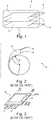
- FIG. 3 We have represented in figure 3 , an accumulator A with a stack of electrochemical cells, the stack being housed in a flexible packaging 6. As shown in this figure 3 , to ensure the tightness of this flexible packaging 6, it is necessary to seal in four sealing strips 60, generally 5 mm in unit width. These bands 60 ultimately form edges. And, when these rims cannot be folded over to the side of the accumulator according to its thickness, which is the case for a stack thickness of less than 5 mm, they constitute a loss of active surface and therefore of surface capacity of the battery. accumulator.
- the substrates on which the active electrode materials are deposited and which each form a current collector of an electrode of the same polarity are connected to each other by welding.
- the welding is performed by ultrasound.
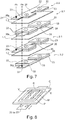
- each positive electrode 2 consists of a substrate made of material electrically conductive 20 supporting on each of these faces 21, 22 the same pattern of active material 23.
- a weld is made on at least one of the sides of the stack between the positive current collectors 20 on the one hand and between those negative 30 on the other hand, by putting them in abutment against each other and thus inserting them between an ultrasonic welding head (probe) Ts and a welding block Bs provided for this purpose.
- probe ultrasonic welding head
- the current collectors 20 or 30 should each protrude from the electrode pattern 23 or 33 by a distance preferably greater than 5 mm. In other words, it is necessary to dedicate to the welding a strip 24 or 34, generally 5 mm in width, on at least one of the sides of the stack of the accumulator A, which therefore also constitutes a loss in surface capacity. .
- US 2015/026970 A1 discloses an electrochemical accumulator packaged in flexible packaging, formed by laminating an anode, a separator and a cathode, each of the electrodes being formed of a conductive substrate having parts of the same section as the active material (placed on either side of the substrate), and other thinner parts, which correspond to the fold lines of the coil of the electrodes.
- CN 104 466 229 A discloses an accumulator comprising several electrode patterns spread over two dimensions to ensure a flexible accumulator.
- the general aim of the invention is to meet this need at least in part.
- the invention relates to an electrochemical accumulator according to claim 1.
- the electrode patterns of the substrate (s) of a given polarity are aligned or else isometric and superimposed with the electrode patterns of the substrate (s) of the opposite polarity, in the direction of stacking.
- an architecture is produced with zones devoid of electrode materials, rigid in themselves and preferably also devoid of separator material.
- the fold lines allow great flexibility of the accumulator by elastic deformation of the flexible packaging, of the current collecting substrates and, where appropriate, of the separator, and this according to several possible configurations from the same basic geometry.
- an accumulator which have both rigid zones and flexible zones.
- the electrode patterns constitute the rigid zones of the accumulator and the flexible zones consist only of the current collecting substrates and of the separator films.
- the number of strips of material required on the one hand for the heat-sealing of the flexible packaging and on the other hand for the welding of the flexible packaging is reduced. substrates same polarity between them.
- the capacity of the accumulator is thus increased, the number of welds is reduced to two and the flexibility conferred on the accumulator is increased.
- the electrode patterns can be of square or rectangular section.
- the areas not supporting the electrode patterns of a current collector substrate are cut out with a shape exactly what is necessary to achieve electrical continuity and to obtain sufficient mechanical resistance to bending. .
- the flexibility of the accumulator is increased.
- these areas without material or free areas are dimensioned to further increase the flexibility of the accumulator and advantageously for some to be able to connect all the substrates supporting electrode patterns of the same polarity by a solder point.
- the substrates support on a main face, at least three isometric and superimposed electrode patterns.
- the substrates support on a main face, four electrode patterns arranged in a square or a rectangle, the first and third substrates being U-shaped in their parts connecting the electrode patterns together while the second and fourth substrates are I-shaped in their parts connecting the electrode patterns together.
- the substrates are of circular section, the electrode patterns of a substrate being of section in a portion of a circle arranged in a circle concentric with that of the substrates.
- the substrates have a section of regular polygon, the electrode patterns of a substrate being of triangular section arranged in a polygon which is homothetic to that of the substrate.
- the substrates are of oblong section, each substrate comprising on at least one of its main faces two electrode patterns each of semi-oblong section arranged facing each other in an oblong section. homothetic to that of the substrate.
- the current collecting substrates are preferably metal strips, with a preferential thickness of between 5 and 50 ⁇ m.
- a strip anode it may advantageously be a copper strip with a thickness of the order of 12 ⁇ m.
- a cathode strip it may advantageously be an aluminum strip with a thickness of the order of 20 ⁇ m.
- the electrode patterns are preferably produced by printing technique, more preferably by screen printing on the current collecting substrates.
- Other printing techniques can be used such as flexography, gravure printing, spray, inkjet, aerosol jet printing ...
- An important advantage of printing techniques is to be able to manufacturing patterns of various sections (square, rectangular, round or more complex) and therefore allows to acquire a certain freedom in the design of the accumulator according to the invention.
- Screen printing may be preferred because it has the advantage of being able to deposit a larger quantity of ink in a single pass, which makes it possible to obtain high grammages and therefore high capacities.
- the production rates are high, compared to the coating which is the conventional process used by battery manufacturers, typically a printing speed of 20 to 25 m / s for screen printing, to be compared to a speed 10 to 15 m / s for coating.
- connections or poles which emerge from the flexible packaging, for the connection of the accumulator to an external circuit can therefore consist either of strips of the current collector substrates itself, preferably of aluminum for the positive electrode and copper for the negative electrode, or metal tabs welded one to the substrates supporting the positive electrode patterns the other to those supporting the negative electrode patterns, preferably also aluminum for the positive electrode and nickel for the negative electrode.
- a thermo-fusible polymer layer preferably chosen from a polyethylene (PE) or a polypropylene (PP), is added between the one or more. flexible packaging films and poles.
- the flexible package preferably consists of a single flexible bag. It can be manufactured from a multilayer composite material consisting of a stack of aluminum layers covered by one or more polymer film (s) laminated by adhesive.
- the polymer covering the aluminum can be chosen from polyethylene (PE), propylene, polyamide (PA) or can be in the form of an adhesive layer consisting of polyester-polyurethane. Showa Denko sells this type of composite materials for use as battery packaging under the references NADR-0N25 / AL40 / CPP40 or No. ADR-0N25 / AL40 / CPP80.
- the flexible bag in accordance with the invention is advantageously based on an aluminized multilayer film, impervious to the electrolyte.
- the accumulator according to the invention can be a Li-ion accumulator, the electrode patterns being made of lithium insertion material.
- the current collecting substrates may be formed by at least one metal foil, preferably of copper or aluminum or metallized on the surface of another metal, for example of aluminum superimposed on copper.
- lithium insertion material electrode is meant here and within the scope of the invention, an electrode pattern comprising at least one lithium insertion material and at least one polymer binder.
- the electrode pattern may additionally comprise an electronic conductor, for example carbon fibers or carbon black.
- lithium insertion material in particular for the positive electrode patterns, is meant here and within the framework of the invention, a material chosen from lithiated oxides comprising manganese of spinel structure, lithiated oxides of lamellar structure and mixtures thereof, lithiated oxides with polyanionic frameworks of formula LiM y (XO z ) n with M representing an element selected from Mn, Fe, Co, Ni, Cu, Mg, Zn, V, Ca, Sr, Ba, Ti, Al, Si, B and Mo, X representing an element chosen from P, Si, Ge, S and As, y, z and n being positive integers.
- M an element selected from Mn, Fe, Co, Ni, Cu, Mg, Zn, V, Ca, Sr, Ba, Ti, Al, Si, B and Mo
- X representing an element chosen from P, Si, Ge, S and As, y, z and n being positive integers.
- lithium insertion material in particular for the negative electrode patterns, also means a material chosen from: titanium oxide, lithiated or not, for example Li 4 Ti 5 O 12 or TiO 2 . More particularly, the material of the negative electrode patterns can be chosen from carbonaceous materials, non-lithiated titanium oxides and their derivatives and lithiated titanium oxides such as Li 4 Ti 5 O 12 and their derivatives and a mixture of those -this.
- lithiumated derivative is meant here and in the context of the invention, compounds of formula Li (4-x1) M x1 Ti 5 O 12 and Li 4 Ti (5-y1) N y1 O 12 , where x1 and y1 are respectively between 0 and 0.2 and M and N are respectively chemical elements chosen from Na, K, Mg, Nb, Al, Ni, Co, Zr, Cr, Mn, Fe, Cu, Zn, Si and Mo.
- non-lithiated derivative is meant here and in the context of the invention, Ti (5-y1) N y1 O 12 , with y1 ranging between 0 and 0.2 and N is a chemical element chosen from Na, K , Mg, Nb, Al, Ni, Co, Zr, Cr, Mn, Fe, Cu, Zn, Si and Mo.
- the anodes are made of graphite and the cathodes of LiFePO 4 .
- separatator is meant here and in the context of the invention, an electrical insulator, an ionic conductor formed by at least one polymer material. Each separator film is cut to the desired pattern by a mechanical process or by laser.
- the polymer is dissolved in a solvent, or in a solvent / non-solvent mixture in the case of a phase inversion process.
- the polymer solution is deposited on the electrode patterns in the form of a thin layer then the solvent is evaporated by passing the electrode through a continuous or static oven.
- the thin layer of the electrolytic component can be porous, dense or gelled in the presence of the electrolyte.
- the thickness of the polymer layer is preferably between 5 and 40 ⁇ m.
- the electrolyte according to the invention can be a liquid formed by a mixture of carbonate and at least one lithium salt.
- lithium salt is preferably meant a salt chosen from LiPF 6 , LiClO 4 , LiBF 4 and LiAsF 6 .
- the electrolyte can comprise one or more ionic liquid, based on lithium ions, namely a salt consisting of lithium cations, complexed with inorganic or organic anions, which has the property of being in the liquid state at ambient temperature.
- An ionic liquid depending on the nature of the anion, can be hydrophilic or hydrophobic.
- ionic liquids mention may be made of ionic liquids based on hydrophobic anions such as trifluoromethanesulfonate (CF 3 SO 3 ), bis (trifluoromethanesulfonate imide [(CF 3 SO 2 ) 2 N] and tris (trifluoromethanesulfonate). methide [(CF 3 SO 2 ) 3 C].
- each electrode pattern on a substrate forming a current collector can be carried out by a usual printing technique such as screen printing, heliography, flexography, spray, etc.
- each negative electrode pattern is larger than the area of each positive electrode pattern. This ensures that all the metal ions of the positive insertion material, such as Li + ions in a lithium accumulator, can migrate towards the negative electrode and thus become inserted into the structure. Besides aligning the positive electrode patterns with those of the negative electrode, it is also possible to increase the area of the negative electrode patterns compared to those of the positive electrode. This may correspond to a strip of active material, added to each side of each negative electrode pattern. An added strip can typically have a width of 1mm.
- the invention thus relates more particularly to the use for electrically supplying a flexible transdermal stimulation electrode, the accumulator being integrated in the envelope of the electrode.
- Another more general use of the accumulator is to supply electric power to any electronic device capable of being deformed so as to be conformed with a location constrained by shapes and / or space.
- RFID RFID type sensors or antennas (standing for “Radio Frequency Identification”) intended to be installed housed in the passenger compartment of a motor vehicle, or in the smallest available corner of the vehicle, for communication. information.
- An accumulator according to the invention is also aimed at the field of flexible electronics with applications such as sensors for smart clothing, flexible type screens, electronic papers, etc. where the final object is subjected to constraints. of repeated deformations.
- the invention is described below with reference to six different embodiments of a flexible Li-ion battery with high capacity obtained by stacking several electrode patterns.
- the Li-ion accumulator comprises a stack of at least a first 20 and at least a second electrically conductive substrate 30 forming a current collector.
- each of the two main faces 21, 22; 31, 32 supports at least two patterns of active electrode material 23; 33.
- the two grounds 23; 33 of each of the faces 21, 22; 31, 32 are distant from each other by defining an area 25; 35 devoid of reasons.
- Each pattern 23; 33 of one of the faces 21; 31 of a substrate 20; 30 is supported in the same zone as a pattern 23; 33 of the other face 22; 32 of the same substrate 20; 30.
- An electrically insulating separator film 1.1 incorporating an electrolyte is arranged in contact with each of the electrode patterns 23; 33 supported by one of the faces of the first 20 and of the second 30 substrate.
- a flexible packaging 6 is arranged to contain the first 20 and the second 30 substrates and the separator film 1, with sealing while being crossed by a first 4 and a second 5 poles of the accumulator respectively connected or constituted by a part of the first 20 or the second substrate.
- the electrode patterns 23 of the first substrate 20 have the same positive polarity and therefore constitute, together with the substrate 20, a first positive electrode 2.1.
- Those 33 of the second substrate 30 are of negative polarity and together with the substrate 30 constitute a first negative electrode 3.1.
- the accumulator according to the invention can comprise at each of the ends of the stack another positive electrode 2.2 and another negative electrode 3.2.
- each of these end electrodes 2.2; 3.2 consists of an electrically conductive substrate forming a current collector each comprising two main faces, one of which 20, 30 supports at least two patterns of active electrode material 23; 33 and the other face is devoid of active material, the two patterns being distant from each other by defining a zone 25; 35 devoid of reasons.
- an additional separator film 1.3 separates the positive end electrode 2.2 from the central negative electrode 3.1 and another additional film 1.2 separates the negative end electrode 3.2 from the central positive electrode 2.1.
- zones 25; 35 devoid of patterns are flexible and thus define the axes or fold lines of the accumulator.
- the negative electrode patterns 33 are aligned with the positive electrode patterns 23.
- each negative electrode pattern 33 is greater than the area of each positive electrode pattern 23.
- the accumulator comprises two output connectors including a positive pole 4 and a negative 5.
- the accumulator architecture according to the invention makes it possible to reduce the number of strips dedicated to the sealing of the flexible packaging and to the welding of the current collectors, which provides a gain in surface capacity and therefore in volume energy density of the accumulator.
- the accumulator A comprises in its central part of the stack a positive electrode 2.1 and a negative electrode 3.1, and at each of the ends of the stack a positive electrode 2.2 and a negative electrode 3.2.
- the central electrodes 2.1; 3.1 include two patterns of active material 23; 33, on each of the faces 21, 22; 31, 32 of the current collectors 20; 30.
- the end electrodes 2.2; 3.2 for their part comprise two patterns of active material 23; 33, on only one of the faces 21; 31 of the current collectors 20; 30.
- the distance D defining a bare zone 25; 35 between the two patterns 23; 33 of the positive electrodes 2.1, 2.2 and of the negative electrodes 3.1, 3.2 of the same face is preferably greater than or equal to 5 mm to leave sufficient space in order to constitute an axis or fold line in this zone 25; 35.
- the cut-out is preferably less than 2/3 the width of the electrode pattern 23; 33 so as not to weaken the electrodes 2.1, 2.2; 3.1, 3.2, that is to say to give them sufficient resistance to tearing.
- the cutting of the substrates 20, 30 makes it possible to produce a weld between them in order to constitute the outputs or poles 4, 5 of the accumulator, at only two points Ps as shown in figure 7 .
- the accumulator according to this example 1 Compared to a battery according to the state of the art, with two accumulators connected in parallel as shown in figure 3 , the accumulator according to this example 1 only requires the installation of five sealing strips 60 instead of eight and a single solder strip 24 instead of two. This therefore provides a gain in surface capacity and therefore in volume energy density for the accumulator according to the invention.
- FIG 8 We illustrated in figure 8 an example of printing by screen printing of the electrode patterns 23 or 33 from a stencil-type printing screen M comprising openings P, produced on a collecting substrate 20 or 30.
- a bead of ink E is deposited directly on the screen M which is supported by a frame C.
- the bead of ink E is then pushed by the doctor blade R at an adjustable speed symbolized by the arrow V.
- the quantity of ink deposited is regulated by the thickness of the printing screen M and by the dimensions of the openings P.
- the pressure applied to the doctor blade R is also adjustable, which makes it possible to more finely adjust the grammage of the electrode.
- the electrode ink E deposited on the current collector 20 or 30 by this screen printing technique is then dried by passing the electrode 2 or 3 through a continuous oven or statically in a ventilated oven.
- the electrodes 2 or 3 are then calendered to a calibrated thickness and / or porosity (s) then cut according to the chosen pattern 23 or 33 by mechanical process or by laser.
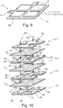
- This example 2 shown in figures 9 to 16 was the subject of a prototype designed to supply electricity to a transdermal electrode for electrostimulation.
- the central positive 2.1 and negative 3.1 electrodes each comprise eight electrode patterns 23; 33, that is to say four per side 21, 22; 31, 32 of current collectors 20; 30.
- the positive 2.2 and negative 3.2 end electrodes each comprise four electrode patterns 23; 33 on only one of the faces 21; 31 of the current collectors 20; 30.
- the accumulator comprises a number of six flexible zones Z2.
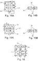
- the positive end electrode 2.2 comprises four electrode patterns 23 interconnected by a single current collector substrate 20.
- the four patterns 23 are located on the same face 21 of the collector.
- the distance e between two adjacent patterns 23 is 9 mm.
- the zone 20s constitutes the welding zone of the positive electrodes 2.1, 2.2.
- the negative end electrode 3.2 comprises four electrode patterns 33 interconnected by a single current collector substrate 30.
- the four patterns 33 are located on the same face 30 of the collector.
- the distance i between two adjacent patterns 23 is 7 mm.
- Zone 30s constitutes the welding zone of the negative electrodes 3.1, 3.2.
- the central positive electrode 2.1 comprises eight electrode patterns 23 interconnected by a single current collector substrate 20.
- Each face 21, 22 of the collector 20 comprises four patterns 23.
- Each of the patterns 23 of a face 21 is in look of a pattern on the other side 22.
- the zone 20s constitutes the welding zone of the positive electrodes 2.1, 2.2.
- the central negative electrode 3.1 comprises eight electrode patterns 33 interconnected by a single current collector substrate 30.
- Each face 31, 32 of the collector 30 comprises four patterns 33.
- Each of the patterns 33 of a face 31 is in look of a pattern on the other side 32.
- the figure 16 represents an insulating separator film 1.1.
- the stacking of the various components of the accumulator is shown in figure 10 . Once the stack has been produced, the positive electrodes 2.1 and 2.2 are welded together according to the weld point produced in the zones 20s, and the positive electrodes 2.1 and 2.2 are welded together according to the weld point produced in the zones 30s.
- Electrode characteristics Electrode type Positive electrode Negative electrode Active ingredient nature LiFePO 4 Graphite % active ingredient 90.5 96 % electronic conductors 5 0 % binder 4.5 4 Accumulator specifications Total surface area excluding connection surfaces (cm 2 ) 29.15 Max thickness (mm) 0.85 Nominal voltage (V) 3.2 Cycling limits (V) 2.6 - 3.7 Surface capacity (mAh / cm 2 ) 3 Expected practical capacity (mAh) 86 Nature of the electrolyte LP10 (LiPF 6 1M in EC / PC / DMC 1/1/3 2% VC)
- the specific capacity of the prototype according to this example 2 was evaluated and is indicated in the form of a curve in figure 17 .
- the accumulator according to this example 2 only requires the installation of six sealing strips 60 instead of 16 and of a sealing strip. solder 24 instead of four. This therefore provides a gain in surface capacity and therefore in volume energy density for the accumulator according to the invention.
- the accumulator A comprises in its central part of the stack a positive electrode 2.1 and a negative electrode 3.1, and at each of the ends of the stack a positive electrode 2.2 and a negative electrode 3.2.
- the central electrodes 2.1; 3.1 include three patterns of active material 23; 33 aligned, on each of the faces 21, 22; 31, 32 of the current collectors 20; 30.
- the end electrodes 2.2; 3.2 for their part include three patterns of active material 23; 33 aligned on only one of the faces 21; 31 of the current collectors 20; 30.
- the accumulator comprises a number of six flexible zones Z2.
- the positive end electrode 2.2 comprises three electrode patterns 23 interconnected by a single current collector substrate 20.
- the three patterns 23 are located on the same face 20 of the collector.
- the zone 20s constitutes the welding zone of the positive electrodes 2.1, 2.2.
- the negative end electrode 3.2 comprises three electrode patterns 33 interconnected by a single current collector substrate 30.
- the three patterns 33 are located on the same face 30 of the collector.
- the central positive electrode 2.1 comprises six electrode patterns 23 interconnected by a single current collector substrate 20.
- Each face 21, 22 of the collector 20 comprises three patterns 23.
- Each of the patterns 23 of a face 21 is in look of a pattern on the other side 22.
- Zone 30s constitutes the welding zone of the negative electrodes 3.1, 3.2.
- the central negative electrode 3.1 comprises six electrode patterns 33 interconnected by a single current collector substrate 30.
- Each face 31, 32 of the collector 30 comprises three patterns 33.
- Each of the patterns 33 of a face 31 is in look of a pattern on the other side 32.
- Zone 30s constitutes the welding zone of the negative electrodes 3.1, 3.2.
- the figure 23 represents an insulating separator film 1.1.
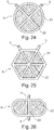
- the accumulator is spherical in shape, with a stack of collecting substrates 20, 30 of circular section and electrode patterns 23; 33 of section in portion of a circle arranged in a circle concentric with that of the substrates.
- the accumulator comprises a number of four zones Z1 occupied by the electrode patterns 23; 33 and which are more rigid than the zones Z2 which are devoid of them and occupied only by the parts of the bare current collectors 25, 35 and the separator 1.
- the accumulator is hexagonal in shape with a stack of collecting substrates 20, 30 of hexagonal section and electrode patterns 23; 33 of triangular section arranged in a hexagon homothetic to that of the substrates 20; 30.
- the accumulator comprises a number of six zones Z1 occupied by the electrode patterns 23; 33 and which are more rigid than the Z2 zones which are devoid of and occupied only by the parts of the bare current collectors 25, 35 and the separator 1.
- the accumulator is oblong in shape with a stack of collecting substrates 20, 30 of oblong section, and two electrode patterns 23; 33 of semi-oblong section arranged facing each other in an oblong section homothetic to that of the substrates 20, 30.
- the accumulator comprises a number of two zones Z1 occupied by the electrode patterns 23; 33 and which are more rigid than the zones Z2 which are devoid of them and occupied only by the parts of bare current collectors 25, 35 and the separator 1.
Claims (10)
- Elektrochemischer Metall-Ionen-Akkumulator (A), umfassend einen Stapel aus den folgenden Elementen:- mindestens ein erstes (20) und mindestens ein zweites (30) elektrisch leitfähiges Substrat, die einen Stromkollektor bilden und jeweils zwei Hauptseiten (21, 22; 31, 32) umfassen, von denen jede mindestens zwei Muster aus Elektrodenaktivmaterial (23; 33) trägt, wobei eine Elektrode (2.1; 3.1) definiert wird, wobei die beiden Muster jeder der Seiten voneinander entfernt sind und dabei einen Bereich (25; 35) ohne Muster definieren, wobei jedes Muster einer Seite eines Substrats in dem gleichen Bereich wie ein Muster der anderen Seite desselben Substrats getragen wird;- mindestens ein elektrisch isolierender Separatorfilm (1.1), der einen Elektrolyten beinhaltet und in Kontakt mit jedem der Elektrodenmuster angeordnet ist, die von der einen der Seiten des ersten und des zweiten Substrats getragen werden;- eine flexible Verpackung (6), die angeordnet ist, um das erste und das zweite Substrat und den Separatorfilm dicht zu enthalten, wobei sie von einem ersten und einem zweiten Pol des Akkumulators durchquert wird, die jeweils durch einen Teil des ersten oder des zweiten Substrats verbunden sind oder daraus bestehen;wobei in dem Akkumulator:- die Elektrodenmuster desselben Substrats die gleiche Polarität haben;- die Elektrodenmuster des zweiten Substrats eine zu denen des ersten Substrats entgegengesetzte Polarität haben;- die Elektrodenmuster des zweiten Substrats mit denen des ersten Substrats in Richtung des Stapels überlagert sind, wobei die Elektrodenmuster des zweiten Substrats isometrisch zu denen des ersten Substrats sind oder die Fläche jedes Musters der negativen Elektrode größer als die Fläche jedes Musters der positiven Elektrode ist;- die Bereiche ohne Muster der Substrate flexibel sind und so Biegelinien des Akkumulators definieren;- die Substrate den gleichen Querschnitt wie die Muster haben in den Bereichen ihrer Seiten, die sie tragen, während sie in den Bereichen ohne Muster einen kleineren Querschnitt haben, wobei die Bereiche ohne Muster Ausschnitte beinhalten, die materiefreie Bereiche zwischen zwei benachbarten Mustern auf derselben Seite eines Substrats erzeugen.
- Akkumulator nach Anspruch 1, umfassend ferner:- zwei Endsubstrate (20, 30) des Stapels, die aus einem dritten und einem vierten elektrisch leitfähigen Substrat bestehen, die einen Stromkollektor bilden und jeweils zwei Hauptseiten umfassen, von denen die eine mindestens zwei Muster aus Elektrodenaktivmaterial trägt und die andere Seite aktivmaterialfrei ist, wobei eine Endelektrode (2.2; 3.2) definiert wird, wobei die beiden Muster voneinander entfernt sind und dabei einen Bereich ohne Muster definieren;- zwei elektrisch isolierende Separatorfilme (1.2, 1.3), von denen der eine in Kontakt mit jedem der Elektrodenmuster, die von der einen der Seiten des ersten Substrats getragen werden, und denen des vierten Substrats angeordnet ist, und der andere in Kontakt mit jedem der Elektrodenmuster, die von der einen der Seiten des zweiten Substrats getragen werden, und denen der ersten Seite des dritten Substrats angeordnet ist;und in dem:- die Elektrodenmuster des dritten Substrats die gleiche Polarität haben wie die des ersten Substrats, während die des vierten Substrats die gleiche Polarität haben wie die des zweiten Substrats;- die Elektrodenmuster des dritten und vierten Substrats mit denen des ersten und des zweiten Substrats in Richtung des Stapels überlagert sind, wobei die Muster der negativen und positiven Elektroden isometrisch sind oder gegebenenfalls die Fläche jedes Musters einer negativen Elektrode größer als die Fläche jedes Musters einer positiven Elektrode ist;- das dritte Substrat an das(die) erste(n) Substrat(e) in mindestens einem Punkt ihrer Bereiche ohne Elektrodenmuster geschweißt ist, während das vierte Substrat an das(die) zweite(n) Substrat(e) in mindestens einem Punkt ihrer Bereiche ohne Elektrodenmuster geschweißt ist.
- Akkumulator nach Anspruch 1 oder 2, wobei die Elektrodenmuster einen quadratischen oder rechteckigen Querschnitt haben.
- Akkumulator nach einem der vorhergehenden Ansprüche, wobei die Substrate auf einer Hauptseite mindestens drei überlagerte Elektrodenmuster tragen, wobei die Muster der negativen und positiven Elektroden isometrisch sind oder gegebenenfalls die Fläche jedes Musters einer negativen Elektrode größer als die Fläche jedes Musters einer positiven Elektrode ist.
- Akkumulator nach einem der Ansprüche 1 bis 3, wobei die Substrate auf einer Hauptseite vier zu einem Quadrat oder Rechteck angeordnete Elektrodenmuster tragen, wobei die ersten und dritten Substrate in ihren die Elektrodenmuster untereinander verbindenden Teilen U-förmig sind, während die ersten und vierten Substrate in ihren die Elektrodenmuster untereinander verbindenden Teilen I-förmig sind.
- Akkumulator nach Anspruch 1 oder 2, wobei die Substrate einen kreisförmigen Querschnitt haben, wobei die Elektrodenmuster eines Substrats den Querschnitt eines Kreisausschnitts haben und gemäß einem Kreis angeordnet sind, der konzentrisch zu dem der Substrate ist.
- Akkumulator nach Anspruch 1 oder 2, wobei die Substrate den Querschnitt eines regelmäßigen Polygons haben, wobei die Elektrodenmuster eines Substrats den Querschnitt eines Dreiecks haben und gemäß einem Polygon angeordnet sind, das homothetisch zu dem des Substrats ist.
- Akkumulator nach Anspruch 1 oder 2, wobei die Substrate von länglichem Querschnitt sind, wobei jedes Substrat auf mindestens einer seiner Hauptseiten zwei Elektrodenmuster mit jeweils halblänglichem Querschnitt umfasst, die einander gegenüber gemäß einem länglichen Querschnitt angeordnet sind, der homothetisch zu dem des Substrats ist.
- Akkumulator nach einem der vorhergehenden Ansprüche, der einen Li-Ionen-Akkumulator darstellt, wobei die Elektrodenmuster aus Lithiumeinlagerungsmaterial sind.
- Verwendung des Akkumulators nach einem der vorhergehenden Ansprüche zur Stromversorgung einer flexiblen Elektrode zur transkutanen Stimulation, wobei der Akkumulator in die Hülle der Elektrode eingearbeitet ist.
Applications Claiming Priority (2)
| Application Number | Priority Date | Filing Date | Title |
|---|---|---|---|
| FR1656537A FR3053842B1 (fr) | 2016-07-07 | 2016-07-07 | Accumulateur electrochimique metal-ion, a capacite elevee et dont la souplesse permet une grande conformabilite |
| PCT/EP2017/067133 WO2018007606A1 (fr) | 2016-07-07 | 2017-07-07 | Accumulateur electrochimique metal-ion, a capacite elevee et dont la souplesse permet une grande conformabilite |
Publications (2)
| Publication Number | Publication Date |
|---|---|
| EP3482432A1 EP3482432A1 (de) | 2019-05-15 |
| EP3482432B1 true EP3482432B1 (de) | 2020-10-14 |
Family
ID=56920795
Family Applications (1)
| Application Number | Title | Priority Date | Filing Date |
|---|---|---|---|
| EP17740701.2A Active EP3482432B1 (de) | 2016-07-07 | 2017-07-07 | Metall-ion akkumulator mit hohe kapazität, wessen flexibilität für eine hohe gleichförmichkeit dient |
Country Status (3)
| Country | Link |
|---|---|
| EP (1) | EP3482432B1 (de) |
| FR (1) | FR3053842B1 (de) |
| WO (1) | WO2018007606A1 (de) |
Families Citing this family (1)
| Publication number | Priority date | Publication date | Assignee | Title |
|---|---|---|---|---|
| CN109786643A (zh) * | 2019-02-01 | 2019-05-21 | 江苏烨晨智能科技有限公司 | 一种电池极片正负极结构 |
Citations (1)
| Publication number | Priority date | Publication date | Assignee | Title |
|---|---|---|---|---|
| CN104466229A (zh) * | 2013-09-25 | 2015-03-25 | 华为技术有限公司 | 一种柔性锂二次电池及其制备方法 |
Family Cites Families (21)
| Publication number | Priority date | Publication date | Assignee | Title |
|---|---|---|---|---|
| JP3397351B2 (ja) | 1992-12-18 | 2003-04-14 | キヤノン株式会社 | 角型あるいはシート型電池及びその製造方法 |
| US5525441A (en) * | 1994-09-13 | 1996-06-11 | Power Conversion, Inc. | Folded electrode configuration for galvanic cells |
| US5776628A (en) * | 1997-06-30 | 1998-07-07 | Wilson Greatbatch Ltd. | Flat-folded, multi-plate electrode assembly |
| GB9900398D0 (en) | 1999-01-08 | 1999-02-24 | Danionics As | Arrangements of electrochemical cells |
| US6528204B1 (en) | 1999-09-22 | 2003-03-04 | Koninklijke Philips Electronics N.V. | Lithium secondary battery comprising individual cells with one another, as well as watches, computers and communication equipment provided with a battery |
| US6294288B1 (en) * | 1999-12-01 | 2001-09-25 | Valence Technology, Inc. | Battery cell having notched layers |
| WO2002033767A1 (en) | 2000-10-13 | 2002-04-25 | Matsushita Electric Industrial Co., Ltd. | Flat square battery |
| US7338733B2 (en) | 2002-04-30 | 2008-03-04 | Sanyo Electric Co., Ltd. | Battery pack |
| US7335448B2 (en) | 2002-05-30 | 2008-02-26 | Matsushita Electric Industrial Co., Ltd. | Lithium ion secondary battery |
| JP2005011660A (ja) * | 2003-06-18 | 2005-01-13 | Nissan Motor Co Ltd | 二次電池用電極及びその製造方法並びにこれを用いた二次電池 |
| JP4324794B2 (ja) | 2004-11-09 | 2009-09-02 | ソニー株式会社 | 負極活物質および二次電池 |
| WO2008023199A1 (en) | 2006-08-24 | 2008-02-28 | Absl Power Solutions Limited | Conformable battery packs |
| JP4251204B2 (ja) | 2006-08-31 | 2009-04-08 | 日産自動車株式会社 | 電池モジュール |
| JP5114036B2 (ja) | 2006-09-08 | 2013-01-09 | Necエナジーデバイス株式会社 | 積層型電池の製造方法 |
| CN102668222A (zh) * | 2009-11-19 | 2012-09-12 | Nec能源元器件株式会社 | 制造锂离子二次电池的方法 |
| FR2955974B1 (fr) | 2010-02-02 | 2012-04-20 | Commissariat Energie Atomique | Accumulateur electrochimique avec emballage comprenant au moins une feuille en polyarylethercetone (paek), feuille et procedes de realisation associes |
| FR2974674B1 (fr) * | 2011-04-26 | 2013-06-28 | Commissariat Energie Atomique | Accumulateur electrochimique li-ion de type bipolaire a capacite augmentee |
| US9343716B2 (en) | 2011-12-29 | 2016-05-17 | Apple Inc. | Flexible battery pack |
| KR101617495B1 (ko) * | 2013-03-04 | 2016-05-03 | 주식회사 엘지화학 | 젤리롤 타입의 전극 조립체 제조방법 및 젤리롤 타입의 폴리머 이차전지 제조방법 |
| WO2015017767A1 (en) | 2013-08-02 | 2015-02-05 | University Of Georgia Research Foundation, Inc. | Cryptosporidium transfection methods and transfected cryptosporidium cells |
| CN103715380B (zh) | 2013-12-30 | 2017-05-17 | 深圳市格瑞普电池有限公司 | 一种柔性穿戴式锂电池 |
-
2016
- 2016-07-07 FR FR1656537A patent/FR3053842B1/fr not_active Expired - Fee Related
-
2017
- 2017-07-07 WO PCT/EP2017/067133 patent/WO2018007606A1/fr unknown
- 2017-07-07 EP EP17740701.2A patent/EP3482432B1/de active Active
Patent Citations (1)
| Publication number | Priority date | Publication date | Assignee | Title |
|---|---|---|---|---|
| CN104466229A (zh) * | 2013-09-25 | 2015-03-25 | 华为技术有限公司 | 一种柔性锂二次电池及其制备方法 |
Also Published As
| Publication number | Publication date |
|---|---|
| EP3482432A1 (de) | 2019-05-15 |
| WO2018007606A1 (fr) | 2018-01-11 |
| FR3053842A1 (fr) | 2018-01-12 |
| FR3053842B1 (fr) | 2020-02-07 |
Similar Documents
| Publication | Publication Date | Title |
|---|---|---|
| EP2583332B1 (de) | Stromabnehmer mit integrierter dichtung sowie zweipolige batterie mit einem derartigen stromabnehmer | |
| EP2702630B1 (de) | Bipolare elektrochemische li-ionenbatterie mit erhöhter kapazität | |
| EP2870655B1 (de) | Stromabnehmer mit integrierter dichtungsvorrichtung, bipolare batterie mit solch einem stromabnehmer | |
| US20130029205A1 (en) | Thin Electrochemical Cell | |
| EP3000141B1 (de) | Bipolare li-ionen-batterie mit verbesserter abdichtung und zugehöriges verfahren zur herstellung | |
| EP3076453B1 (de) | Elektrochemische vorrichtung, wie mikrobatterie oder elektrochromsystem, die mit einer einkapselungsschicht umgeben ist, die eine abdichtfolie und eine klebefolie umfasst, und herstellungsverfahren einer solchen vorrichtung | |
| EP3381073A1 (de) | Zweipolige lithium-ionen-batterie | |
| EP3649694B1 (de) | Verfahren zur herstellung eines elektrochemischen bündels einer metall-ionenbatterie mittels einer gelpolymerelektrolytmembran und zugehörige batterien | |
| EP3311432A1 (de) | Verfahren zur herstellung eines elektrochemischen bündels für eine metall-ionen-batterie mit faltung oder aufwicklung der folienenden um sich selbst | |
| EP2904654B1 (de) | Bipolare batterie mit einem stromkollektor mit eingebauter dichtung und verfahren zur herstellung solch einer batterie | |
| WO2014013373A1 (fr) | Batterie li-ion bipolaire a étanchéité améliorée et procédé de réalisation associé | |
| JP4670275B2 (ja) | バイポーラ電池および組電池 | |
| EP3486971B1 (de) | Poröser stromkollektor mit dichter elektrischer anschlusszunge für dichtes elektrochemisches system | |
| EP3346522B1 (de) | Elektrochemischer akkumulator mit ebenem aufbau, der teilweise durch druckverfahren erzielt wird | |
| EP3482432B1 (de) | Metall-ion akkumulator mit hohe kapazität, wessen flexibilität für eine hohe gleichförmichkeit dient | |
| EP3346538B1 (de) | Elektrochemischer lithium-ionen-akkumulator mit verbesserter dichtigkeit | |
| EP3327819B1 (de) | Metallionen-akkumulator mit einem stapel elektroden, gekennzeichnet durch eine hohe energiedichte und eine hohe kapazität | |
| EP3327818B1 (de) | Metallionen batterie mit einem elektrodenstapel aufweisend hohe kapazität und hohe leistung | |
| EP4175014A1 (de) | Stromabnehmer eines instrumentierungselements eines elektrochemischen systems mit durch wärmeversiegelung eines heissschmelzpolymers an einem elektrisch leitenden band gestützten elektrisch leitenden band. |
Legal Events
| Date | Code | Title | Description |
|---|---|---|---|
| STAA | Information on the status of an ep patent application or granted ep patent |
Free format text: STATUS: UNKNOWN |
|
| STAA | Information on the status of an ep patent application or granted ep patent |
Free format text: STATUS: THE INTERNATIONAL PUBLICATION HAS BEEN MADE |
|
| PUAI | Public reference made under article 153(3) epc to a published international application that has entered the european phase |
Free format text: ORIGINAL CODE: 0009012 |
|
| STAA | Information on the status of an ep patent application or granted ep patent |
Free format text: STATUS: REQUEST FOR EXAMINATION WAS MADE |
|
| 17P | Request for examination filed |
Effective date: 20190103 |
|
| AK | Designated contracting states |
Kind code of ref document: A1 Designated state(s): AL AT BE BG CH CY CZ DE DK EE ES FI FR GB GR HR HU IE IS IT LI LT LU LV MC MK MT NL NO PL PT RO RS SE SI SK SM TR |
|
| AX | Request for extension of the european patent |
Extension state: BA ME |
|
| DAV | Request for validation of the european patent (deleted) | ||
| DAX | Request for extension of the european patent (deleted) | ||
| RIN1 | Information on inventor provided before grant (corrected) |
Inventor name: SALOMON, JEREMIE Inventor name: KARST, NICOLAS Inventor name: PERRAUD, SIMON |
|
| GRAP | Despatch of communication of intention to grant a patent |
Free format text: ORIGINAL CODE: EPIDOSNIGR1 |
|
| STAA | Information on the status of an ep patent application or granted ep patent |
Free format text: STATUS: GRANT OF PATENT IS INTENDED |
|
| INTG | Intention to grant announced |
Effective date: 20200616 |
|
| GRAS | Grant fee paid |
Free format text: ORIGINAL CODE: EPIDOSNIGR3 |
|
| GRAA | (expected) grant |
Free format text: ORIGINAL CODE: 0009210 |
|
| STAA | Information on the status of an ep patent application or granted ep patent |
Free format text: STATUS: THE PATENT HAS BEEN GRANTED |
|
| AK | Designated contracting states |
Kind code of ref document: B1 Designated state(s): AL AT BE BG CH CY CZ DE DK EE ES FI FR GB GR HR HU IE IS IT LI LT LU LV MC MK MT NL NO PL PT RO RS SE SI SK SM TR |
|
| REG | Reference to a national code |
Ref country code: GB Ref legal event code: FG4D Free format text: NOT ENGLISH |
|
| REG | Reference to a national code |
Ref country code: AT Ref legal event code: REF Ref document number: 1324454 Country of ref document: AT Kind code of ref document: T Effective date: 20201015 Ref country code: CH Ref legal event code: EP |
|
| REG | Reference to a national code |
Ref country code: DE Ref legal event code: R096 Ref document number: 602017025484 Country of ref document: DE |
|
| REG | Reference to a national code |
Ref country code: IE Ref legal event code: FG4D Free format text: LANGUAGE OF EP DOCUMENT: FRENCH |
|
| REG | Reference to a national code |
Ref country code: DE Ref legal event code: R079 Ref document number: 602017025484 Country of ref document: DE Free format text: PREVIOUS MAIN CLASS: H01M0002260000 Ipc: H01M0050531000 |
|
| REG | Reference to a national code |
Ref country code: AT Ref legal event code: MK05 Ref document number: 1324454 Country of ref document: AT Kind code of ref document: T Effective date: 20201014 |
|
| REG | Reference to a national code |
Ref country code: NL Ref legal event code: MP Effective date: 20201014 |
|
| PG25 | Lapsed in a contracting state [announced via postgrant information from national office to epo] |
Ref country code: PT Free format text: LAPSE BECAUSE OF FAILURE TO SUBMIT A TRANSLATION OF THE DESCRIPTION OR TO PAY THE FEE WITHIN THE PRESCRIBED TIME-LIMIT Effective date: 20210215 Ref country code: RS Free format text: LAPSE BECAUSE OF FAILURE TO SUBMIT A TRANSLATION OF THE DESCRIPTION OR TO PAY THE FEE WITHIN THE PRESCRIBED TIME-LIMIT Effective date: 20201014 Ref country code: NO Free format text: LAPSE BECAUSE OF FAILURE TO SUBMIT A TRANSLATION OF THE DESCRIPTION OR TO PAY THE FEE WITHIN THE PRESCRIBED TIME-LIMIT Effective date: 20210114 Ref country code: FI Free format text: LAPSE BECAUSE OF FAILURE TO SUBMIT A TRANSLATION OF THE DESCRIPTION OR TO PAY THE FEE WITHIN THE PRESCRIBED TIME-LIMIT Effective date: 20201014 Ref country code: GR Free format text: LAPSE BECAUSE OF FAILURE TO SUBMIT A TRANSLATION OF THE DESCRIPTION OR TO PAY THE FEE WITHIN THE PRESCRIBED TIME-LIMIT Effective date: 20210115 |
|
| REG | Reference to a national code |
Ref country code: LT Ref legal event code: MG4D |
|
| PG25 | Lapsed in a contracting state [announced via postgrant information from national office to epo] |
Ref country code: ES Free format text: LAPSE BECAUSE OF FAILURE TO SUBMIT A TRANSLATION OF THE DESCRIPTION OR TO PAY THE FEE WITHIN THE PRESCRIBED TIME-LIMIT Effective date: 20201014 Ref country code: AT Free format text: LAPSE BECAUSE OF FAILURE TO SUBMIT A TRANSLATION OF THE DESCRIPTION OR TO PAY THE FEE WITHIN THE PRESCRIBED TIME-LIMIT Effective date: 20201014 Ref country code: BG Free format text: LAPSE BECAUSE OF FAILURE TO SUBMIT A TRANSLATION OF THE DESCRIPTION OR TO PAY THE FEE WITHIN THE PRESCRIBED TIME-LIMIT Effective date: 20210114 Ref country code: LV Free format text: LAPSE BECAUSE OF FAILURE TO SUBMIT A TRANSLATION OF THE DESCRIPTION OR TO PAY THE FEE WITHIN THE PRESCRIBED TIME-LIMIT Effective date: 20201014 Ref country code: IS Free format text: LAPSE BECAUSE OF FAILURE TO SUBMIT A TRANSLATION OF THE DESCRIPTION OR TO PAY THE FEE WITHIN THE PRESCRIBED TIME-LIMIT Effective date: 20210214 Ref country code: PL Free format text: LAPSE BECAUSE OF FAILURE TO SUBMIT A TRANSLATION OF THE DESCRIPTION OR TO PAY THE FEE WITHIN THE PRESCRIBED TIME-LIMIT Effective date: 20201014 Ref country code: SE Free format text: LAPSE BECAUSE OF FAILURE TO SUBMIT A TRANSLATION OF THE DESCRIPTION OR TO PAY THE FEE WITHIN THE PRESCRIBED TIME-LIMIT Effective date: 20201014 |
|
| PG25 | Lapsed in a contracting state [announced via postgrant information from national office to epo] |
Ref country code: NL Free format text: LAPSE BECAUSE OF FAILURE TO SUBMIT A TRANSLATION OF THE DESCRIPTION OR TO PAY THE FEE WITHIN THE PRESCRIBED TIME-LIMIT Effective date: 20201014 Ref country code: HR Free format text: LAPSE BECAUSE OF FAILURE TO SUBMIT A TRANSLATION OF THE DESCRIPTION OR TO PAY THE FEE WITHIN THE PRESCRIBED TIME-LIMIT Effective date: 20201014 |
|
| REG | Reference to a national code |
Ref country code: DE Ref legal event code: R097 Ref document number: 602017025484 Country of ref document: DE |
|
| PG25 | Lapsed in a contracting state [announced via postgrant information from national office to epo] |
Ref country code: SM Free format text: LAPSE BECAUSE OF FAILURE TO SUBMIT A TRANSLATION OF THE DESCRIPTION OR TO PAY THE FEE WITHIN THE PRESCRIBED TIME-LIMIT Effective date: 20201014 Ref country code: LT Free format text: LAPSE BECAUSE OF FAILURE TO SUBMIT A TRANSLATION OF THE DESCRIPTION OR TO PAY THE FEE WITHIN THE PRESCRIBED TIME-LIMIT Effective date: 20201014 Ref country code: EE Free format text: LAPSE BECAUSE OF FAILURE TO SUBMIT A TRANSLATION OF THE DESCRIPTION OR TO PAY THE FEE WITHIN THE PRESCRIBED TIME-LIMIT Effective date: 20201014 Ref country code: CZ Free format text: LAPSE BECAUSE OF FAILURE TO SUBMIT A TRANSLATION OF THE DESCRIPTION OR TO PAY THE FEE WITHIN THE PRESCRIBED TIME-LIMIT Effective date: 20201014 Ref country code: RO Free format text: LAPSE BECAUSE OF FAILURE TO SUBMIT A TRANSLATION OF THE DESCRIPTION OR TO PAY THE FEE WITHIN THE PRESCRIBED TIME-LIMIT Effective date: 20201014 Ref country code: SK Free format text: LAPSE BECAUSE OF FAILURE TO SUBMIT A TRANSLATION OF THE DESCRIPTION OR TO PAY THE FEE WITHIN THE PRESCRIBED TIME-LIMIT Effective date: 20201014 |
|
| PLBE | No opposition filed within time limit |
Free format text: ORIGINAL CODE: 0009261 |
|
| STAA | Information on the status of an ep patent application or granted ep patent |
Free format text: STATUS: NO OPPOSITION FILED WITHIN TIME LIMIT |
|
| PG25 | Lapsed in a contracting state [announced via postgrant information from national office to epo] |
Ref country code: DK Free format text: LAPSE BECAUSE OF FAILURE TO SUBMIT A TRANSLATION OF THE DESCRIPTION OR TO PAY THE FEE WITHIN THE PRESCRIBED TIME-LIMIT Effective date: 20201014 |
|
| 26N | No opposition filed |
Effective date: 20210715 |
|
| PG25 | Lapsed in a contracting state [announced via postgrant information from national office to epo] |
Ref country code: AL Free format text: LAPSE BECAUSE OF FAILURE TO SUBMIT A TRANSLATION OF THE DESCRIPTION OR TO PAY THE FEE WITHIN THE PRESCRIBED TIME-LIMIT Effective date: 20201014 Ref country code: IT Free format text: LAPSE BECAUSE OF FAILURE TO SUBMIT A TRANSLATION OF THE DESCRIPTION OR TO PAY THE FEE WITHIN THE PRESCRIBED TIME-LIMIT Effective date: 20201014 |
|
| PG25 | Lapsed in a contracting state [announced via postgrant information from national office to epo] |
Ref country code: SI Free format text: LAPSE BECAUSE OF FAILURE TO SUBMIT A TRANSLATION OF THE DESCRIPTION OR TO PAY THE FEE WITHIN THE PRESCRIBED TIME-LIMIT Effective date: 20201014 |
|
| REG | Reference to a national code |
Ref country code: DE Ref legal event code: R119 Ref document number: 602017025484 Country of ref document: DE |
|
| REG | Reference to a national code |
Ref country code: CH Ref legal event code: PL |
|
| GBPC | Gb: european patent ceased through non-payment of renewal fee |
Effective date: 20210707 |
|
| PG25 | Lapsed in a contracting state [announced via postgrant information from national office to epo] |
Ref country code: MC Free format text: LAPSE BECAUSE OF FAILURE TO SUBMIT A TRANSLATION OF THE DESCRIPTION OR TO PAY THE FEE WITHIN THE PRESCRIBED TIME-LIMIT Effective date: 20201014 |
|
| REG | Reference to a national code |
Ref country code: BE Ref legal event code: MM Effective date: 20210731 |
|
| PG25 | Lapsed in a contracting state [announced via postgrant information from national office to epo] |
Ref country code: LI Free format text: LAPSE BECAUSE OF NON-PAYMENT OF DUE FEES Effective date: 20210731 Ref country code: GB Free format text: LAPSE BECAUSE OF NON-PAYMENT OF DUE FEES Effective date: 20210707 Ref country code: DE Free format text: LAPSE BECAUSE OF NON-PAYMENT OF DUE FEES Effective date: 20220201 Ref country code: CH Free format text: LAPSE BECAUSE OF NON-PAYMENT OF DUE FEES Effective date: 20210731 |
|
| PG25 | Lapsed in a contracting state [announced via postgrant information from national office to epo] |
Ref country code: IS Free format text: LAPSE BECAUSE OF FAILURE TO SUBMIT A TRANSLATION OF THE DESCRIPTION OR TO PAY THE FEE WITHIN THE PRESCRIBED TIME-LIMIT Effective date: 20210214 Ref country code: LU Free format text: LAPSE BECAUSE OF NON-PAYMENT OF DUE FEES Effective date: 20210707 |
|
| PG25 | Lapsed in a contracting state [announced via postgrant information from national office to epo] |
Ref country code: IE Free format text: LAPSE BECAUSE OF NON-PAYMENT OF DUE FEES Effective date: 20210707 Ref country code: BE Free format text: LAPSE BECAUSE OF NON-PAYMENT OF DUE FEES Effective date: 20210731 |
|
| PG25 | Lapsed in a contracting state [announced via postgrant information from national office to epo] |
Ref country code: CY Free format text: LAPSE BECAUSE OF FAILURE TO SUBMIT A TRANSLATION OF THE DESCRIPTION OR TO PAY THE FEE WITHIN THE PRESCRIBED TIME-LIMIT Effective date: 20201014 |
|
| PG25 | Lapsed in a contracting state [announced via postgrant information from national office to epo] |
Ref country code: HU Free format text: LAPSE BECAUSE OF FAILURE TO SUBMIT A TRANSLATION OF THE DESCRIPTION OR TO PAY THE FEE WITHIN THE PRESCRIBED TIME-LIMIT; INVALID AB INITIO Effective date: 20170707 |
|
| PGFP | Annual fee paid to national office [announced via postgrant information from national office to epo] |
Ref country code: FR Payment date: 20230720 Year of fee payment: 7 |
|
| PG25 | Lapsed in a contracting state [announced via postgrant information from national office to epo] |
Ref country code: MK Free format text: LAPSE BECAUSE OF FAILURE TO SUBMIT A TRANSLATION OF THE DESCRIPTION OR TO PAY THE FEE WITHIN THE PRESCRIBED TIME-LIMIT Effective date: 20201014 |