EP3482432B1 - Metal ion electrochemical accumulator having high capacity and whose flexibility allows a high conformability - Google Patents
Metal ion electrochemical accumulator having high capacity and whose flexibility allows a high conformability Download PDFInfo
- Publication number
- EP3482432B1 EP3482432B1 EP17740701.2A EP17740701A EP3482432B1 EP 3482432 B1 EP3482432 B1 EP 3482432B1 EP 17740701 A EP17740701 A EP 17740701A EP 3482432 B1 EP3482432 B1 EP 3482432B1
- Authority
- EP
- European Patent Office
- Prior art keywords
- substrate
- accumulator
- electrode
- units
- substrates
- Prior art date
- Legal status (The legal status is an assumption and is not a legal conclusion. Google has not performed a legal analysis and makes no representation as to the accuracy of the status listed.)
- Active
Links
- 229910021645 metal ion Inorganic materials 0.000 title claims description 8
- 239000000758 substrate Substances 0.000 claims description 146
- 229910001416 lithium ion Inorganic materials 0.000 claims description 39
- 238000009459 flexible packaging Methods 0.000 claims description 27
- 239000000463 material Substances 0.000 claims description 24
- 229910052744 lithium Inorganic materials 0.000 claims description 14
- WHXSMMKQMYFTQS-UHFFFAOYSA-N Lithium Chemical compound [Li] WHXSMMKQMYFTQS-UHFFFAOYSA-N 0.000 claims description 13
- 239000003792 electrolyte Substances 0.000 claims description 13
- 239000011149 active material Substances 0.000 claims description 12
- 238000003780 insertion Methods 0.000 claims description 11
- 230000037431 insertion Effects 0.000 claims description 11
- 239000007772 electrode material Substances 0.000 claims description 8
- 230000000638 stimulation Effects 0.000 claims description 2
- HBBGRARXTFLTSG-UHFFFAOYSA-N Lithium ion Chemical compound [Li+] HBBGRARXTFLTSG-UHFFFAOYSA-N 0.000 description 29
- 238000003466 welding Methods 0.000 description 25
- 239000010408 film Substances 0.000 description 19
- -1 polyethylene Polymers 0.000 description 17
- 229920000642 polymer Polymers 0.000 description 15
- 238000007789 sealing Methods 0.000 description 15
- 229910052782 aluminium Inorganic materials 0.000 description 14
- 238000000034 method Methods 0.000 description 12
- XAGFODPZIPBFFR-UHFFFAOYSA-N aluminium Chemical compound [Al] XAGFODPZIPBFFR-UHFFFAOYSA-N 0.000 description 11
- 238000007639 printing Methods 0.000 description 10
- 229910052802 copper Inorganic materials 0.000 description 9
- 239000010949 copper Substances 0.000 description 9
- 238000007650 screen-printing Methods 0.000 description 8
- 229910052710 silicon Inorganic materials 0.000 description 8
- 239000004698 Polyethylene Substances 0.000 description 7
- 230000008901 benefit Effects 0.000 description 7
- 229920000573 polyethylene Polymers 0.000 description 7
- 239000010936 titanium Substances 0.000 description 7
- RYGMFSIKBFXOCR-UHFFFAOYSA-N Copper Chemical compound [Cu] RYGMFSIKBFXOCR-UHFFFAOYSA-N 0.000 description 6
- 239000002131 composite material Substances 0.000 description 6
- 239000010410 layer Substances 0.000 description 6
- 239000000203 mixture Substances 0.000 description 6
- 239000000243 solution Substances 0.000 description 6
- OKTJSMMVPCPJKN-UHFFFAOYSA-N Carbon Chemical compound [C] OKTJSMMVPCPJKN-UHFFFAOYSA-N 0.000 description 5
- PXHVJJICTQNCMI-UHFFFAOYSA-N Nickel Chemical compound [Ni] PXHVJJICTQNCMI-UHFFFAOYSA-N 0.000 description 5
- 229920003171 Poly (ethylene oxide) Polymers 0.000 description 5
- 239000002608 ionic liquid Substances 0.000 description 5
- 230000008569 process Effects 0.000 description 5
- 239000004952 Polyamide Substances 0.000 description 4
- 229910045601 alloy Inorganic materials 0.000 description 4
- 239000000956 alloy Substances 0.000 description 4
- 239000000470 constituent Substances 0.000 description 4
- 229910002804 graphite Inorganic materials 0.000 description 4
- 239000010439 graphite Substances 0.000 description 4
- 229910003002 lithium salt Inorganic materials 0.000 description 4
- 159000000002 lithium salts Chemical class 0.000 description 4
- 229910052748 manganese Inorganic materials 0.000 description 4
- 239000011572 manganese Substances 0.000 description 4
- 238000004519 manufacturing process Methods 0.000 description 4
- 229910052751 metal Inorganic materials 0.000 description 4
- 239000002184 metal Substances 0.000 description 4
- 229910052759 nickel Inorganic materials 0.000 description 4
- 238000004806 packaging method and process Methods 0.000 description 4
- 229920002647 polyamide Polymers 0.000 description 4
- 239000010703 silicon Substances 0.000 description 4
- 229910000679 solder Inorganic materials 0.000 description 4
- OGIDPMRJRNCKJF-UHFFFAOYSA-N titanium oxide Inorganic materials [Ti]=O OGIDPMRJRNCKJF-UHFFFAOYSA-N 0.000 description 4
- 229910010707 LiFePO 4 Inorganic materials 0.000 description 3
- 239000002033 PVDF binder Substances 0.000 description 3
- 239000004743 Polypropylene Substances 0.000 description 3
- 241001080024 Telles Species 0.000 description 3
- 238000005520 cutting process Methods 0.000 description 3
- 238000013461 design Methods 0.000 description 3
- 229910052742 iron Inorganic materials 0.000 description 3
- XEEYBQQBJWHFJM-UHFFFAOYSA-N iron Substances [Fe] XEEYBQQBJWHFJM-UHFFFAOYSA-N 0.000 description 3
- 239000007788 liquid Substances 0.000 description 3
- 229910052749 magnesium Inorganic materials 0.000 description 3
- 229920003229 poly(methyl methacrylate) Polymers 0.000 description 3
- 229920000139 polyethylene terephthalate Polymers 0.000 description 3
- 239000005020 polyethylene terephthalate Substances 0.000 description 3
- 239000004926 polymethyl methacrylate Substances 0.000 description 3
- 229920001155 polypropylene Polymers 0.000 description 3
- 229920002981 polyvinylidene fluoride Polymers 0.000 description 3
- 239000002904 solvent Substances 0.000 description 3
- 229910052725 zinc Inorganic materials 0.000 description 3
- 239000011701 zinc Substances 0.000 description 3
- IJGRMHOSHXDMSA-UHFFFAOYSA-N Atomic nitrogen Chemical compound N#N IJGRMHOSHXDMSA-UHFFFAOYSA-N 0.000 description 2
- 229910013870 LiPF 6 Inorganic materials 0.000 description 2
- 229910010413 TiO 2 Inorganic materials 0.000 description 2
- 230000009471 action Effects 0.000 description 2
- 239000004480 active ingredient Substances 0.000 description 2
- 239000012790 adhesive layer Substances 0.000 description 2
- 150000001450 anions Chemical class 0.000 description 2
- 239000011324 bead Substances 0.000 description 2
- 238000005452 bending Methods 0.000 description 2
- 150000001768 cations Chemical class 0.000 description 2
- 229920002678 cellulose Polymers 0.000 description 2
- 239000001913 cellulose Substances 0.000 description 2
- 229910052729 chemical element Inorganic materials 0.000 description 2
- 229910052804 chromium Inorganic materials 0.000 description 2
- 239000011651 chromium Substances 0.000 description 2
- 239000011248 coating agent Substances 0.000 description 2
- 238000000576 coating method Methods 0.000 description 2
- 238000006073 displacement reaction Methods 0.000 description 2
- 239000011532 electronic conductor Substances 0.000 description 2
- 238000007647 flexography Methods 0.000 description 2
- HCDGVLDPFQMKDK-UHFFFAOYSA-N hexafluoropropylene Chemical compound FC(F)=C(F)C(F)(F)F HCDGVLDPFQMKDK-UHFFFAOYSA-N 0.000 description 2
- 230000002209 hydrophobic effect Effects 0.000 description 2
- 238000009434 installation Methods 0.000 description 2
- 238000010297 mechanical methods and process Methods 0.000 description 2
- 230000005226 mechanical processes and functions Effects 0.000 description 2
- 229910052750 molybdenum Inorganic materials 0.000 description 2
- 229910052758 niobium Inorganic materials 0.000 description 2
- SOQBVABWOPYFQZ-UHFFFAOYSA-N oxygen(2-);titanium(4+) Chemical class [O-2].[O-2].[Ti+4] SOQBVABWOPYFQZ-UHFFFAOYSA-N 0.000 description 2
- 229920005569 poly(vinylidene fluoride-co-hexafluoropropylene) Polymers 0.000 description 2
- 229920006260 polyaryletherketone Polymers 0.000 description 2
- 229920006254 polymer film Polymers 0.000 description 2
- 229920002635 polyurethane Polymers 0.000 description 2
- 239000004814 polyurethane Substances 0.000 description 2
- 239000011118 polyvinyl acetate Substances 0.000 description 2
- 229910052700 potassium Inorganic materials 0.000 description 2
- QQONPFPTGQHPMA-UHFFFAOYSA-N propylene Natural products CC=C QQONPFPTGQHPMA-UHFFFAOYSA-N 0.000 description 2
- 125000004805 propylene group Chemical group [H]C([H])([H])C([H])([*:1])C([H])([H])[*:2] 0.000 description 2
- 239000002994 raw material Substances 0.000 description 2
- 150000003839 salts Chemical class 0.000 description 2
- 229910052708 sodium Inorganic materials 0.000 description 2
- 238000005476 soldering Methods 0.000 description 2
- 239000007921 spray Substances 0.000 description 2
- ITMCEJHCFYSIIV-UHFFFAOYSA-M triflate Chemical compound [O-]S(=O)(=O)C(F)(F)F ITMCEJHCFYSIIV-UHFFFAOYSA-M 0.000 description 2
- 238000004804 winding Methods 0.000 description 2
- 229910052726 zirconium Inorganic materials 0.000 description 2
- 229910000838 Al alloy Inorganic materials 0.000 description 1
- CIWBSHSKHKDKBQ-JLAZNSOCSA-N Ascorbic acid Chemical compound OC[C@H](O)[C@H]1OC(=O)C(O)=C1O CIWBSHSKHKDKBQ-JLAZNSOCSA-N 0.000 description 1
- 229920000049 Carbon (fiber) Polymers 0.000 description 1
- BVKZGUZCCUSVTD-UHFFFAOYSA-L Carbonate Chemical compound [O-]C([O-])=O BVKZGUZCCUSVTD-UHFFFAOYSA-L 0.000 description 1
- 229910015015 LiAsF 6 Inorganic materials 0.000 description 1
- 229910013063 LiBF 4 Inorganic materials 0.000 description 1
- 229910013684 LiClO 4 Inorganic materials 0.000 description 1
- 229910012851 LiCoO 2 Inorganic materials 0.000 description 1
- 229910002992 LiNi0.33Mn0.33Co0.33O2 Inorganic materials 0.000 description 1
- 229910001290 LiPF6 Inorganic materials 0.000 description 1
- JLVVSXFLKOJNIY-UHFFFAOYSA-N Magnesium ion Chemical compound [Mg+2] JLVVSXFLKOJNIY-UHFFFAOYSA-N 0.000 description 1
- PWHULOQIROXLJO-UHFFFAOYSA-N Manganese Chemical compound [Mn] PWHULOQIROXLJO-UHFFFAOYSA-N 0.000 description 1
- FKNQFGJONOIPTF-UHFFFAOYSA-N Sodium cation Chemical compound [Na+] FKNQFGJONOIPTF-UHFFFAOYSA-N 0.000 description 1
- ATJFFYVFTNAWJD-UHFFFAOYSA-N Tin Chemical compound [Sn] ATJFFYVFTNAWJD-UHFFFAOYSA-N 0.000 description 1
- GWEVSGVZZGPLCZ-UHFFFAOYSA-N Titan oxide Chemical compound O=[Ti]=O GWEVSGVZZGPLCZ-UHFFFAOYSA-N 0.000 description 1
- RTAQQCXQSZGOHL-UHFFFAOYSA-N Titanium Chemical compound [Ti] RTAQQCXQSZGOHL-UHFFFAOYSA-N 0.000 description 1
- 239000007983 Tris buffer Substances 0.000 description 1
- XTXRWKRVRITETP-UHFFFAOYSA-N Vinyl acetate Chemical compound CC(=O)OC=C XTXRWKRVRITETP-UHFFFAOYSA-N 0.000 description 1
- 239000004676 acrylonitrile butadiene styrene Substances 0.000 description 1
- 230000004913 activation Effects 0.000 description 1
- 239000000654 additive Substances 0.000 description 1
- 239000000853 adhesive Substances 0.000 description 1
- 238000004026 adhesive bonding Methods 0.000 description 1
- 230000001070 adhesive effect Effects 0.000 description 1
- 239000000443 aerosol Substances 0.000 description 1
- 150000001449 anionic compounds Chemical class 0.000 description 1
- 229910052785 arsenic Inorganic materials 0.000 description 1
- QVGXLLKOCUKJST-UHFFFAOYSA-N atomic oxygen Chemical compound [O] QVGXLLKOCUKJST-UHFFFAOYSA-N 0.000 description 1
- 230000003416 augmentation Effects 0.000 description 1
- 229910052788 barium Inorganic materials 0.000 description 1
- 239000011230 binding agent Substances 0.000 description 1
- 229910052796 boron Inorganic materials 0.000 description 1
- 229910052791 calcium Inorganic materials 0.000 description 1
- 238000003490 calendering Methods 0.000 description 1
- 229910052799 carbon Inorganic materials 0.000 description 1
- 239000006229 carbon black Substances 0.000 description 1
- 239000004917 carbon fiber Substances 0.000 description 1
- 239000003575 carbonaceous material Substances 0.000 description 1
- 150000004649 carbonic acid derivatives Chemical class 0.000 description 1
- 239000000919 ceramic Substances 0.000 description 1
- 238000004891 communication Methods 0.000 description 1
- 150000001875 compounds Chemical class 0.000 description 1
- 239000002482 conductive additive Substances 0.000 description 1
- 239000004020 conductor Substances 0.000 description 1
- 229920001577 copolymer Polymers 0.000 description 1
- 230000001351 cycling effect Effects 0.000 description 1
- 230000007423 decrease Effects 0.000 description 1
- 238000009831 deintercalation Methods 0.000 description 1
- 230000008021 deposition Effects 0.000 description 1
- 238000007599 discharging Methods 0.000 description 1
- 230000005489 elastic deformation Effects 0.000 description 1
- 230000005611 electricity Effects 0.000 description 1
- 239000011888 foil Substances 0.000 description 1
- 239000000499 gel Substances 0.000 description 1
- 229910052732 germanium Inorganic materials 0.000 description 1
- 238000007646 gravure printing Methods 0.000 description 1
- 239000010416 ion conductor Substances 0.000 description 1
- 229920000554 ionomer Polymers 0.000 description 1
- 238000010030 laminating Methods 0.000 description 1
- 229940006487 lithium cation Drugs 0.000 description 1
- 239000011777 magnesium Substances 0.000 description 1
- 229910001425 magnesium ion Inorganic materials 0.000 description 1
- LGRLWUINFJPLSH-UHFFFAOYSA-N methanide Chemical compound [CH3-] LGRLWUINFJPLSH-UHFFFAOYSA-N 0.000 description 1
- 239000000178 monomer Substances 0.000 description 1
- 239000011185 multilayer composite material Substances 0.000 description 1
- 229910052757 nitrogen Inorganic materials 0.000 description 1
- 239000000615 nonconductor Substances 0.000 description 1
- 150000002891 organic anions Chemical class 0.000 description 1
- 239000005486 organic electrolyte Substances 0.000 description 1
- 239000003960 organic solvent Substances 0.000 description 1
- 229910052760 oxygen Inorganic materials 0.000 description 1
- 239000001301 oxygen Substances 0.000 description 1
- 229920006280 packaging film Polymers 0.000 description 1
- 239000012785 packaging film Substances 0.000 description 1
- 229910052698 phosphorus Inorganic materials 0.000 description 1
- 229920005596 polymer binder Polymers 0.000 description 1
- 239000002491 polymer binding agent Substances 0.000 description 1
- 239000002861 polymer material Substances 0.000 description 1
- 229920000098 polyolefin Polymers 0.000 description 1
- 229920002689 polyvinyl acetate Polymers 0.000 description 1
- 238000003672 processing method Methods 0.000 description 1
- 230000005855 radiation Effects 0.000 description 1
- 230000009467 reduction Effects 0.000 description 1
- 230000001105 regulatory effect Effects 0.000 description 1
- 239000000523 sample Substances 0.000 description 1
- 229910001415 sodium ion Inorganic materials 0.000 description 1
- 239000007787 solid Substances 0.000 description 1
- 239000011877 solvent mixture Substances 0.000 description 1
- 229910052596 spinel Inorganic materials 0.000 description 1
- 239000011029 spinel Substances 0.000 description 1
- 239000010935 stainless steel Substances 0.000 description 1
- 229910001220 stainless steel Inorganic materials 0.000 description 1
- 230000003068 static effect Effects 0.000 description 1
- 229910052712 strontium Inorganic materials 0.000 description 1
- 229910052717 sulfur Inorganic materials 0.000 description 1
- 239000010409 thin film Substances 0.000 description 1
- 229910052719 titanium Inorganic materials 0.000 description 1
- 238000002604 ultrasonography Methods 0.000 description 1
- 229910052720 vanadium Inorganic materials 0.000 description 1
- XLYOFNOQVPJJNP-UHFFFAOYSA-N water Substances O XLYOFNOQVPJJNP-UHFFFAOYSA-N 0.000 description 1
- 229910001868 water Inorganic materials 0.000 description 1
Images


Classifications
-
- H—ELECTRICITY
- H01—ELECTRIC ELEMENTS
- H01M—PROCESSES OR MEANS, e.g. BATTERIES, FOR THE DIRECT CONVERSION OF CHEMICAL ENERGY INTO ELECTRICAL ENERGY
- H01M10/00—Secondary cells; Manufacture thereof
- H01M10/05—Accumulators with non-aqueous electrolyte
- H01M10/058—Construction or manufacture
- H01M10/0585—Construction or manufacture of accumulators having only flat construction elements, i.e. flat positive electrodes, flat negative electrodes and flat separators
-
- H—ELECTRICITY
- H01—ELECTRIC ELEMENTS
- H01M—PROCESSES OR MEANS, e.g. BATTERIES, FOR THE DIRECT CONVERSION OF CHEMICAL ENERGY INTO ELECTRICAL ENERGY
- H01M50/00—Constructional details or processes of manufacture of the non-active parts of electrochemical cells other than fuel cells, e.g. hybrid cells
- H01M50/50—Current conducting connections for cells or batteries
- H01M50/531—Electrode connections inside a battery casing
- H01M50/54—Connection of several leads or tabs of plate-like electrode stacks, e.g. electrode pole straps or bridges
-
- H—ELECTRICITY
- H01—ELECTRIC ELEMENTS
- H01M—PROCESSES OR MEANS, e.g. BATTERIES, FOR THE DIRECT CONVERSION OF CHEMICAL ENERGY INTO ELECTRICAL ENERGY
- H01M10/00—Secondary cells; Manufacture thereof
- H01M10/04—Construction or manufacture in general
- H01M10/0436—Small-sized flat cells or batteries for portable equipment
-
- H—ELECTRICITY
- H01—ELECTRIC ELEMENTS
- H01M—PROCESSES OR MEANS, e.g. BATTERIES, FOR THE DIRECT CONVERSION OF CHEMICAL ENERGY INTO ELECTRICAL ENERGY
- H01M10/00—Secondary cells; Manufacture thereof
- H01M10/05—Accumulators with non-aqueous electrolyte
- H01M10/052—Li-accumulators
- H01M10/0525—Rocking-chair batteries, i.e. batteries with lithium insertion or intercalation in both electrodes; Lithium-ion batteries
-
- H—ELECTRICITY
- H01—ELECTRIC ELEMENTS
- H01M—PROCESSES OR MEANS, e.g. BATTERIES, FOR THE DIRECT CONVERSION OF CHEMICAL ENERGY INTO ELECTRICAL ENERGY
- H01M4/00—Electrodes
- H01M4/02—Electrodes composed of, or comprising, active material
- H01M4/13—Electrodes for accumulators with non-aqueous electrolyte, e.g. for lithium-accumulators; Processes of manufacture thereof
-
- H—ELECTRICITY
- H01—ELECTRIC ELEMENTS
- H01M—PROCESSES OR MEANS, e.g. BATTERIES, FOR THE DIRECT CONVERSION OF CHEMICAL ENERGY INTO ELECTRICAL ENERGY
- H01M4/00—Electrodes
- H01M4/02—Electrodes composed of, or comprising, active material
- H01M4/64—Carriers or collectors
- H01M4/70—Carriers or collectors characterised by shape or form
-
- Y—GENERAL TAGGING OF NEW TECHNOLOGICAL DEVELOPMENTS; GENERAL TAGGING OF CROSS-SECTIONAL TECHNOLOGIES SPANNING OVER SEVERAL SECTIONS OF THE IPC; TECHNICAL SUBJECTS COVERED BY FORMER USPC CROSS-REFERENCE ART COLLECTIONS [XRACs] AND DIGESTS
- Y02—TECHNOLOGIES OR APPLICATIONS FOR MITIGATION OR ADAPTATION AGAINST CLIMATE CHANGE
- Y02E—REDUCTION OF GREENHOUSE GAS [GHG] EMISSIONS, RELATED TO ENERGY GENERATION, TRANSMISSION OR DISTRIBUTION
- Y02E60/00—Enabling technologies; Technologies with a potential or indirect contribution to GHG emissions mitigation
- Y02E60/10—Energy storage using batteries
-
- Y—GENERAL TAGGING OF NEW TECHNOLOGICAL DEVELOPMENTS; GENERAL TAGGING OF CROSS-SECTIONAL TECHNOLOGIES SPANNING OVER SEVERAL SECTIONS OF THE IPC; TECHNICAL SUBJECTS COVERED BY FORMER USPC CROSS-REFERENCE ART COLLECTIONS [XRACs] AND DIGESTS
- Y02—TECHNOLOGIES OR APPLICATIONS FOR MITIGATION OR ADAPTATION AGAINST CLIMATE CHANGE
- Y02P—CLIMATE CHANGE MITIGATION TECHNOLOGIES IN THE PRODUCTION OR PROCESSING OF GOODS
- Y02P70/00—Climate change mitigation technologies in the production process for final industrial or consumer products
- Y02P70/50—Manufacturing or production processes characterised by the final manufactured product
Definitions
- the present invention relates to the field of metal-ion electrochemical generators, which operate according to the principle of insertion or deinsertion, or in other words intercalation-deintercalation, of metal ions in at least one electrode.
- It relates more particularly to an electrochemical lithium or lithium-ion accumulator.
- the invention relates to the production of a metal-ion electrochemical accumulator which exhibits both flexibility allowing it great conformability and high capacity.
- Lithium-ion accumulator Although described with reference to a Lithium-ion accumulator, the invention applies to any metal-ion electrochemical accumulator, that is to say also Sodium-ion, Magnesium-ion, Aluminum-ion, etc.
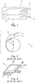
- a lithium-ion battery or accumulator usually comprises at least one electrochemical cell C consisting of an electrolyte component 1, impregnated in a separator making it possible to electrically isolate the electrodes, between a positive electrode or cathode 2 and a negative electrode or anode 3, a current collector 4 connected to the cathode 2, a current collector 5 connected to the anode 3 and finally, a package 6 arranged to contain the electrochemical cell with sealing against water, oxygen and nitrogen, while being crossed by part of the current collectors 4, 5.
- the electrolyte component 1 can be in solid, liquid or gel form.
- the component may comprise a separator made of polymer, ceramic or microporous composite soaked in organic electrolyte (s) or of ionic liquid type which allows the displacement of the lithium ion from the cathode to the 'anode during the charging process and vice versa during the discharging process, which in the latter case generates the current, by displacement of electrons in the external circuit.
- the electrolyte is generally a mixture of organic solvents, for example carbonates to which is added a lithium salt, typically LiPF6.
- the positive electrode or cathode 2 is made of lithium cation insertion materials, such as LiFePO 4 , LiCoO 2 , LiNi 0.33 Mn 0.33 Co 0.33 O 2 .
- the negative electrode or anode 3 is very often made of carbon graphite or of Li 4 TiO 5 O 12 (titanate material), optionally also based on silicon or on a composite formed on the basis of silicon.
- a negative electrode of a lithium-ion battery can be formed from a single alloy, or a mixture of alloys, or a mixture of alloy (s) and other insertion material (s) lithium (graphite, in synthetic or natural form, Li 4 Ti 5 O 12 , TiO 2, etc.), optionally also based on silicon or based on lithium, or based on tin and their alloys or of composite formed from silicon.
- This negative electrode just like the positive electrode, can also contain electronic conductive additives as well as polymer additives which give it mechanical properties and electrochemical performance suitable for the lithium-ion battery application or its method of implementation.
- the current collector 4 connected to the positive electrode is generally made of aluminum.
- the current collector 5 connected to the negative electrode is generally made of copper, nickel-plated copper or aluminum.
- a lithium-ion battery or accumulator can obviously comprise a plurality of electrochemical cells which are stacked one on top of the other.
- a Li-ion battery or accumulator uses a couple of materials at the anode and cathode allowing it to operate at a voltage level high, typically between 3 and 4.1 volts.
- the packaging is then respectively either rigid and in a way constitutes a case and is flexible.
- Rigid packaging are used when the targeted applications are restrictive where a long lifespan is sought, for example with much higher pressures to withstand and a stricter required level of sealing, typically less than 10 -8 mbar.l / s, or in highly constrained environments such as aeronautics or space.
- the constituent material of a Li-ion accumulator case is usually metallic, typically an aluminum alloy or stainless steel or a rigid polymer such as, for example, acrylonitrile butadiene styrene (ABS).
- Flexible packaging is usually made from a multi-layered composite material consisting of a stack of layers of aluminum covered by one or more polymer film (s) laminated by gluing.
- the polymer covering the aluminum is chosen from polyethylene (PE), propylene, polyamide (PA) or can be in the form of an adhesive layer consisting of polyester-polyurethane.
- PE polyethylene
- PA polyamide
- the Showa Denko company markets this type of composite material for use as a battery packaging under the references NADR-0N25 / AL40 / CPP40 or No. ADR-0N25 / AL40 / CPP80.
- a flexible accumulator commonly known in English as “ Thin Film Battery”, is most often made up of a single electrochemical cell.
- the total thickness of the accumulator with its flexible packaging is generally less than 0.6 mm, which allows it to be bent with a radius of curvature between 20 and 30 mm, which depends on the dimensions and the chemistry of the materials. electrodes, and this without altering the performance during operation of the accumulator.
- the bending limit of a stacked accumulator is estimated when it has a thickness between 1.5 and 2 mm.
- a cell stack accumulator can be bent to a relatively large radius of curvature, between 100 and 500 mm. Beyond this, from 2 mm, the accumulator is completely rigid.
- the patent application WO 2013/101316 discloses an architectural solution according to which flexible junction zones are created between different accumulators of the same battery, each accumulator being rigid because it consists of a stack of several electrochemical cells. Reference may be made in particular to figure 3 of this application where the flexible junctions are clearly shown.
- the battery has a high capacity provided by the large number of cells and benefits from a certain flexibility allowing it to conform by virtue of the flexible junction zones.
- the accumulators with stack of cells are interconnected by the connectors and a flexible packaging is common to all the accumulators.
- the patent US5693105 proposes an architecture of an accumulator consisting of several electrochemical cells interconnected by a single polymer separator, which is continuous and by current collectors common to two adjacent cells, which gives the accumulator a certain flexibility in terms of junctions formed by the continuous separator and the current collectors.
- the main drawback of this architecture is the poor seal between the cells. Since the separator is porous or conductor of lithium ions, the electrolyte can navigate between the different cells and thus create ionic bridges. These ionic bridges cause the electrochemical performance to drop.
- FIG. 3 We have represented in figure 3 , an accumulator A with a stack of electrochemical cells, the stack being housed in a flexible packaging 6. As shown in this figure 3 , to ensure the tightness of this flexible packaging 6, it is necessary to seal in four sealing strips 60, generally 5 mm in unit width. These bands 60 ultimately form edges. And, when these rims cannot be folded over to the side of the accumulator according to its thickness, which is the case for a stack thickness of less than 5 mm, they constitute a loss of active surface and therefore of surface capacity of the battery. accumulator.
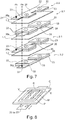
- the substrates on which the active electrode materials are deposited and which each form a current collector of an electrode of the same polarity are connected to each other by welding.
- the welding is performed by ultrasound.
- each positive electrode 2 consists of a substrate made of material electrically conductive 20 supporting on each of these faces 21, 22 the same pattern of active material 23.
- a weld is made on at least one of the sides of the stack between the positive current collectors 20 on the one hand and between those negative 30 on the other hand, by putting them in abutment against each other and thus inserting them between an ultrasonic welding head (probe) Ts and a welding block Bs provided for this purpose.
- probe ultrasonic welding head
- the current collectors 20 or 30 should each protrude from the electrode pattern 23 or 33 by a distance preferably greater than 5 mm. In other words, it is necessary to dedicate to the welding a strip 24 or 34, generally 5 mm in width, on at least one of the sides of the stack of the accumulator A, which therefore also constitutes a loss in surface capacity. .
- US 2015/026970 A1 discloses an electrochemical accumulator packaged in flexible packaging, formed by laminating an anode, a separator and a cathode, each of the electrodes being formed of a conductive substrate having parts of the same section as the active material (placed on either side of the substrate), and other thinner parts, which correspond to the fold lines of the coil of the electrodes.
- CN 104 466 229 A discloses an accumulator comprising several electrode patterns spread over two dimensions to ensure a flexible accumulator.
- the general aim of the invention is to meet this need at least in part.
- the invention relates to an electrochemical accumulator according to claim 1.
- the electrode patterns of the substrate (s) of a given polarity are aligned or else isometric and superimposed with the electrode patterns of the substrate (s) of the opposite polarity, in the direction of stacking.
- an architecture is produced with zones devoid of electrode materials, rigid in themselves and preferably also devoid of separator material.
- the fold lines allow great flexibility of the accumulator by elastic deformation of the flexible packaging, of the current collecting substrates and, where appropriate, of the separator, and this according to several possible configurations from the same basic geometry.
- an accumulator which have both rigid zones and flexible zones.
- the electrode patterns constitute the rigid zones of the accumulator and the flexible zones consist only of the current collecting substrates and of the separator films.
- the number of strips of material required on the one hand for the heat-sealing of the flexible packaging and on the other hand for the welding of the flexible packaging is reduced. substrates same polarity between them.
- the capacity of the accumulator is thus increased, the number of welds is reduced to two and the flexibility conferred on the accumulator is increased.
- the electrode patterns can be of square or rectangular section.
- the areas not supporting the electrode patterns of a current collector substrate are cut out with a shape exactly what is necessary to achieve electrical continuity and to obtain sufficient mechanical resistance to bending. .
- the flexibility of the accumulator is increased.
- these areas without material or free areas are dimensioned to further increase the flexibility of the accumulator and advantageously for some to be able to connect all the substrates supporting electrode patterns of the same polarity by a solder point.
- the substrates support on a main face, at least three isometric and superimposed electrode patterns.
- the substrates support on a main face, four electrode patterns arranged in a square or a rectangle, the first and third substrates being U-shaped in their parts connecting the electrode patterns together while the second and fourth substrates are I-shaped in their parts connecting the electrode patterns together.
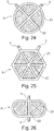
- the substrates are of circular section, the electrode patterns of a substrate being of section in a portion of a circle arranged in a circle concentric with that of the substrates.
- the substrates have a section of regular polygon, the electrode patterns of a substrate being of triangular section arranged in a polygon which is homothetic to that of the substrate.
- the substrates are of oblong section, each substrate comprising on at least one of its main faces two electrode patterns each of semi-oblong section arranged facing each other in an oblong section. homothetic to that of the substrate.
- the current collecting substrates are preferably metal strips, with a preferential thickness of between 5 and 50 ⁇ m.
- a strip anode it may advantageously be a copper strip with a thickness of the order of 12 ⁇ m.
- a cathode strip it may advantageously be an aluminum strip with a thickness of the order of 20 ⁇ m.
- the electrode patterns are preferably produced by printing technique, more preferably by screen printing on the current collecting substrates.
- Other printing techniques can be used such as flexography, gravure printing, spray, inkjet, aerosol jet printing ...
- An important advantage of printing techniques is to be able to manufacturing patterns of various sections (square, rectangular, round or more complex) and therefore allows to acquire a certain freedom in the design of the accumulator according to the invention.
- Screen printing may be preferred because it has the advantage of being able to deposit a larger quantity of ink in a single pass, which makes it possible to obtain high grammages and therefore high capacities.
- the production rates are high, compared to the coating which is the conventional process used by battery manufacturers, typically a printing speed of 20 to 25 m / s for screen printing, to be compared to a speed 10 to 15 m / s for coating.
- connections or poles which emerge from the flexible packaging, for the connection of the accumulator to an external circuit can therefore consist either of strips of the current collector substrates itself, preferably of aluminum for the positive electrode and copper for the negative electrode, or metal tabs welded one to the substrates supporting the positive electrode patterns the other to those supporting the negative electrode patterns, preferably also aluminum for the positive electrode and nickel for the negative electrode.
- a thermo-fusible polymer layer preferably chosen from a polyethylene (PE) or a polypropylene (PP), is added between the one or more. flexible packaging films and poles.
- the flexible package preferably consists of a single flexible bag. It can be manufactured from a multilayer composite material consisting of a stack of aluminum layers covered by one or more polymer film (s) laminated by adhesive.
- the polymer covering the aluminum can be chosen from polyethylene (PE), propylene, polyamide (PA) or can be in the form of an adhesive layer consisting of polyester-polyurethane. Showa Denko sells this type of composite materials for use as battery packaging under the references NADR-0N25 / AL40 / CPP40 or No. ADR-0N25 / AL40 / CPP80.
- the flexible bag in accordance with the invention is advantageously based on an aluminized multilayer film, impervious to the electrolyte.
- the accumulator according to the invention can be a Li-ion accumulator, the electrode patterns being made of lithium insertion material.
- the current collecting substrates may be formed by at least one metal foil, preferably of copper or aluminum or metallized on the surface of another metal, for example of aluminum superimposed on copper.
- lithium insertion material electrode is meant here and within the scope of the invention, an electrode pattern comprising at least one lithium insertion material and at least one polymer binder.
- the electrode pattern may additionally comprise an electronic conductor, for example carbon fibers or carbon black.
- lithium insertion material in particular for the positive electrode patterns, is meant here and within the framework of the invention, a material chosen from lithiated oxides comprising manganese of spinel structure, lithiated oxides of lamellar structure and mixtures thereof, lithiated oxides with polyanionic frameworks of formula LiM y (XO z ) n with M representing an element selected from Mn, Fe, Co, Ni, Cu, Mg, Zn, V, Ca, Sr, Ba, Ti, Al, Si, B and Mo, X representing an element chosen from P, Si, Ge, S and As, y, z and n being positive integers.
- M an element selected from Mn, Fe, Co, Ni, Cu, Mg, Zn, V, Ca, Sr, Ba, Ti, Al, Si, B and Mo
- X representing an element chosen from P, Si, Ge, S and As, y, z and n being positive integers.
- lithium insertion material in particular for the negative electrode patterns, also means a material chosen from: titanium oxide, lithiated or not, for example Li 4 Ti 5 O 12 or TiO 2 . More particularly, the material of the negative electrode patterns can be chosen from carbonaceous materials, non-lithiated titanium oxides and their derivatives and lithiated titanium oxides such as Li 4 Ti 5 O 12 and their derivatives and a mixture of those -this.
- lithiumated derivative is meant here and in the context of the invention, compounds of formula Li (4-x1) M x1 Ti 5 O 12 and Li 4 Ti (5-y1) N y1 O 12 , where x1 and y1 are respectively between 0 and 0.2 and M and N are respectively chemical elements chosen from Na, K, Mg, Nb, Al, Ni, Co, Zr, Cr, Mn, Fe, Cu, Zn, Si and Mo.
- non-lithiated derivative is meant here and in the context of the invention, Ti (5-y1) N y1 O 12 , with y1 ranging between 0 and 0.2 and N is a chemical element chosen from Na, K , Mg, Nb, Al, Ni, Co, Zr, Cr, Mn, Fe, Cu, Zn, Si and Mo.
- the anodes are made of graphite and the cathodes of LiFePO 4 .
- separatator is meant here and in the context of the invention, an electrical insulator, an ionic conductor formed by at least one polymer material. Each separator film is cut to the desired pattern by a mechanical process or by laser.
- the polymer is dissolved in a solvent, or in a solvent / non-solvent mixture in the case of a phase inversion process.
- the polymer solution is deposited on the electrode patterns in the form of a thin layer then the solvent is evaporated by passing the electrode through a continuous or static oven.
- the thin layer of the electrolytic component can be porous, dense or gelled in the presence of the electrolyte.
- the thickness of the polymer layer is preferably between 5 and 40 ⁇ m.
- the electrolyte according to the invention can be a liquid formed by a mixture of carbonate and at least one lithium salt.
- lithium salt is preferably meant a salt chosen from LiPF 6 , LiClO 4 , LiBF 4 and LiAsF 6 .
- the electrolyte can comprise one or more ionic liquid, based on lithium ions, namely a salt consisting of lithium cations, complexed with inorganic or organic anions, which has the property of being in the liquid state at ambient temperature.
- An ionic liquid depending on the nature of the anion, can be hydrophilic or hydrophobic.
- ionic liquids mention may be made of ionic liquids based on hydrophobic anions such as trifluoromethanesulfonate (CF 3 SO 3 ), bis (trifluoromethanesulfonate imide [(CF 3 SO 2 ) 2 N] and tris (trifluoromethanesulfonate). methide [(CF 3 SO 2 ) 3 C].
- each electrode pattern on a substrate forming a current collector can be carried out by a usual printing technique such as screen printing, heliography, flexography, spray, etc.
- each negative electrode pattern is larger than the area of each positive electrode pattern. This ensures that all the metal ions of the positive insertion material, such as Li + ions in a lithium accumulator, can migrate towards the negative electrode and thus become inserted into the structure. Besides aligning the positive electrode patterns with those of the negative electrode, it is also possible to increase the area of the negative electrode patterns compared to those of the positive electrode. This may correspond to a strip of active material, added to each side of each negative electrode pattern. An added strip can typically have a width of 1mm.
- the invention thus relates more particularly to the use for electrically supplying a flexible transdermal stimulation electrode, the accumulator being integrated in the envelope of the electrode.
- Another more general use of the accumulator is to supply electric power to any electronic device capable of being deformed so as to be conformed with a location constrained by shapes and / or space.
- RFID RFID type sensors or antennas (standing for “Radio Frequency Identification”) intended to be installed housed in the passenger compartment of a motor vehicle, or in the smallest available corner of the vehicle, for communication. information.
- An accumulator according to the invention is also aimed at the field of flexible electronics with applications such as sensors for smart clothing, flexible type screens, electronic papers, etc. where the final object is subjected to constraints. of repeated deformations.
- the invention is described below with reference to six different embodiments of a flexible Li-ion battery with high capacity obtained by stacking several electrode patterns.
- the Li-ion accumulator comprises a stack of at least a first 20 and at least a second electrically conductive substrate 30 forming a current collector.
- each of the two main faces 21, 22; 31, 32 supports at least two patterns of active electrode material 23; 33.
- the two grounds 23; 33 of each of the faces 21, 22; 31, 32 are distant from each other by defining an area 25; 35 devoid of reasons.
- Each pattern 23; 33 of one of the faces 21; 31 of a substrate 20; 30 is supported in the same zone as a pattern 23; 33 of the other face 22; 32 of the same substrate 20; 30.
- An electrically insulating separator film 1.1 incorporating an electrolyte is arranged in contact with each of the electrode patterns 23; 33 supported by one of the faces of the first 20 and of the second 30 substrate.
- a flexible packaging 6 is arranged to contain the first 20 and the second 30 substrates and the separator film 1, with sealing while being crossed by a first 4 and a second 5 poles of the accumulator respectively connected or constituted by a part of the first 20 or the second substrate.
- the electrode patterns 23 of the first substrate 20 have the same positive polarity and therefore constitute, together with the substrate 20, a first positive electrode 2.1.
- Those 33 of the second substrate 30 are of negative polarity and together with the substrate 30 constitute a first negative electrode 3.1.
- the accumulator according to the invention can comprise at each of the ends of the stack another positive electrode 2.2 and another negative electrode 3.2.
- each of these end electrodes 2.2; 3.2 consists of an electrically conductive substrate forming a current collector each comprising two main faces, one of which 20, 30 supports at least two patterns of active electrode material 23; 33 and the other face is devoid of active material, the two patterns being distant from each other by defining a zone 25; 35 devoid of reasons.
- an additional separator film 1.3 separates the positive end electrode 2.2 from the central negative electrode 3.1 and another additional film 1.2 separates the negative end electrode 3.2 from the central positive electrode 2.1.
- zones 25; 35 devoid of patterns are flexible and thus define the axes or fold lines of the accumulator.
- the negative electrode patterns 33 are aligned with the positive electrode patterns 23.
- each negative electrode pattern 33 is greater than the area of each positive electrode pattern 23.
- the accumulator comprises two output connectors including a positive pole 4 and a negative 5.
- the accumulator architecture according to the invention makes it possible to reduce the number of strips dedicated to the sealing of the flexible packaging and to the welding of the current collectors, which provides a gain in surface capacity and therefore in volume energy density of the accumulator.
- the accumulator A comprises in its central part of the stack a positive electrode 2.1 and a negative electrode 3.1, and at each of the ends of the stack a positive electrode 2.2 and a negative electrode 3.2.
- the central electrodes 2.1; 3.1 include two patterns of active material 23; 33, on each of the faces 21, 22; 31, 32 of the current collectors 20; 30.
- the end electrodes 2.2; 3.2 for their part comprise two patterns of active material 23; 33, on only one of the faces 21; 31 of the current collectors 20; 30.
- the distance D defining a bare zone 25; 35 between the two patterns 23; 33 of the positive electrodes 2.1, 2.2 and of the negative electrodes 3.1, 3.2 of the same face is preferably greater than or equal to 5 mm to leave sufficient space in order to constitute an axis or fold line in this zone 25; 35.
- the cut-out is preferably less than 2/3 the width of the electrode pattern 23; 33 so as not to weaken the electrodes 2.1, 2.2; 3.1, 3.2, that is to say to give them sufficient resistance to tearing.
- the cutting of the substrates 20, 30 makes it possible to produce a weld between them in order to constitute the outputs or poles 4, 5 of the accumulator, at only two points Ps as shown in figure 7 .
- the accumulator according to this example 1 Compared to a battery according to the state of the art, with two accumulators connected in parallel as shown in figure 3 , the accumulator according to this example 1 only requires the installation of five sealing strips 60 instead of eight and a single solder strip 24 instead of two. This therefore provides a gain in surface capacity and therefore in volume energy density for the accumulator according to the invention.
- FIG 8 We illustrated in figure 8 an example of printing by screen printing of the electrode patterns 23 or 33 from a stencil-type printing screen M comprising openings P, produced on a collecting substrate 20 or 30.
- a bead of ink E is deposited directly on the screen M which is supported by a frame C.
- the bead of ink E is then pushed by the doctor blade R at an adjustable speed symbolized by the arrow V.
- the quantity of ink deposited is regulated by the thickness of the printing screen M and by the dimensions of the openings P.
- the pressure applied to the doctor blade R is also adjustable, which makes it possible to more finely adjust the grammage of the electrode.
- the electrode ink E deposited on the current collector 20 or 30 by this screen printing technique is then dried by passing the electrode 2 or 3 through a continuous oven or statically in a ventilated oven.
- the electrodes 2 or 3 are then calendered to a calibrated thickness and / or porosity (s) then cut according to the chosen pattern 23 or 33 by mechanical process or by laser.
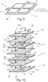
- This example 2 shown in figures 9 to 16 was the subject of a prototype designed to supply electricity to a transdermal electrode for electrostimulation.
- the central positive 2.1 and negative 3.1 electrodes each comprise eight electrode patterns 23; 33, that is to say four per side 21, 22; 31, 32 of current collectors 20; 30.
- the positive 2.2 and negative 3.2 end electrodes each comprise four electrode patterns 23; 33 on only one of the faces 21; 31 of the current collectors 20; 30.
- the accumulator comprises a number of six flexible zones Z2.
- the positive end electrode 2.2 comprises four electrode patterns 23 interconnected by a single current collector substrate 20.
- the four patterns 23 are located on the same face 21 of the collector.
- the distance e between two adjacent patterns 23 is 9 mm.
- the zone 20s constitutes the welding zone of the positive electrodes 2.1, 2.2.
- the negative end electrode 3.2 comprises four electrode patterns 33 interconnected by a single current collector substrate 30.
- the four patterns 33 are located on the same face 30 of the collector.
- the distance i between two adjacent patterns 23 is 7 mm.
- Zone 30s constitutes the welding zone of the negative electrodes 3.1, 3.2.
- the central positive electrode 2.1 comprises eight electrode patterns 23 interconnected by a single current collector substrate 20.
- Each face 21, 22 of the collector 20 comprises four patterns 23.
- Each of the patterns 23 of a face 21 is in look of a pattern on the other side 22.
- the zone 20s constitutes the welding zone of the positive electrodes 2.1, 2.2.
- the central negative electrode 3.1 comprises eight electrode patterns 33 interconnected by a single current collector substrate 30.
- Each face 31, 32 of the collector 30 comprises four patterns 33.
- Each of the patterns 33 of a face 31 is in look of a pattern on the other side 32.
- the figure 16 represents an insulating separator film 1.1.
- the stacking of the various components of the accumulator is shown in figure 10 . Once the stack has been produced, the positive electrodes 2.1 and 2.2 are welded together according to the weld point produced in the zones 20s, and the positive electrodes 2.1 and 2.2 are welded together according to the weld point produced in the zones 30s.
- Electrode characteristics Electrode type Positive electrode Negative electrode Active ingredient nature LiFePO 4 Graphite % active ingredient 90.5 96 % electronic conductors 5 0 % binder 4.5 4 Accumulator specifications Total surface area excluding connection surfaces (cm 2 ) 29.15 Max thickness (mm) 0.85 Nominal voltage (V) 3.2 Cycling limits (V) 2.6 - 3.7 Surface capacity (mAh / cm 2 ) 3 Expected practical capacity (mAh) 86 Nature of the electrolyte LP10 (LiPF 6 1M in EC / PC / DMC 1/1/3 2% VC)
- the specific capacity of the prototype according to this example 2 was evaluated and is indicated in the form of a curve in figure 17 .
- the accumulator according to this example 2 only requires the installation of six sealing strips 60 instead of 16 and of a sealing strip. solder 24 instead of four. This therefore provides a gain in surface capacity and therefore in volume energy density for the accumulator according to the invention.
- the accumulator A comprises in its central part of the stack a positive electrode 2.1 and a negative electrode 3.1, and at each of the ends of the stack a positive electrode 2.2 and a negative electrode 3.2.
- the central electrodes 2.1; 3.1 include three patterns of active material 23; 33 aligned, on each of the faces 21, 22; 31, 32 of the current collectors 20; 30.
- the end electrodes 2.2; 3.2 for their part include three patterns of active material 23; 33 aligned on only one of the faces 21; 31 of the current collectors 20; 30.
- the accumulator comprises a number of six flexible zones Z2.
- the positive end electrode 2.2 comprises three electrode patterns 23 interconnected by a single current collector substrate 20.
- the three patterns 23 are located on the same face 20 of the collector.
- the zone 20s constitutes the welding zone of the positive electrodes 2.1, 2.2.
- the negative end electrode 3.2 comprises three electrode patterns 33 interconnected by a single current collector substrate 30.
- the three patterns 33 are located on the same face 30 of the collector.
- the central positive electrode 2.1 comprises six electrode patterns 23 interconnected by a single current collector substrate 20.
- Each face 21, 22 of the collector 20 comprises three patterns 23.
- Each of the patterns 23 of a face 21 is in look of a pattern on the other side 22.
- Zone 30s constitutes the welding zone of the negative electrodes 3.1, 3.2.
- the central negative electrode 3.1 comprises six electrode patterns 33 interconnected by a single current collector substrate 30.
- Each face 31, 32 of the collector 30 comprises three patterns 33.
- Each of the patterns 33 of a face 31 is in look of a pattern on the other side 32.
- Zone 30s constitutes the welding zone of the negative electrodes 3.1, 3.2.
- the figure 23 represents an insulating separator film 1.1.
- the accumulator is spherical in shape, with a stack of collecting substrates 20, 30 of circular section and electrode patterns 23; 33 of section in portion of a circle arranged in a circle concentric with that of the substrates.
- the accumulator comprises a number of four zones Z1 occupied by the electrode patterns 23; 33 and which are more rigid than the zones Z2 which are devoid of them and occupied only by the parts of the bare current collectors 25, 35 and the separator 1.
- the accumulator is hexagonal in shape with a stack of collecting substrates 20, 30 of hexagonal section and electrode patterns 23; 33 of triangular section arranged in a hexagon homothetic to that of the substrates 20; 30.
- the accumulator comprises a number of six zones Z1 occupied by the electrode patterns 23; 33 and which are more rigid than the Z2 zones which are devoid of and occupied only by the parts of the bare current collectors 25, 35 and the separator 1.
- the accumulator is oblong in shape with a stack of collecting substrates 20, 30 of oblong section, and two electrode patterns 23; 33 of semi-oblong section arranged facing each other in an oblong section homothetic to that of the substrates 20, 30.
- the accumulator comprises a number of two zones Z1 occupied by the electrode patterns 23; 33 and which are more rigid than the zones Z2 which are devoid of them and occupied only by the parts of bare current collectors 25, 35 and the separator 1.
Description
La présente invention concerne le domaine des générateurs électrochimiques métal-ion, qui fonctionnent selon le principe d'insertion ou de désinsertion, ou autrement dit intercalation-désintercalation, d'ions métal dans au moins une électrode.The present invention relates to the field of metal-ion electrochemical generators, which operate according to the principle of insertion or deinsertion, or in other words intercalation-deintercalation, of metal ions in at least one electrode.
Elle concerne plus particulièrement un accumulateur électrochimique au lithium ou lithium-ion.It relates more particularly to an electrochemical lithium or lithium-ion accumulator.
L'invention a trait à la réalisation d'un accumulateur électrochimique métal-ion qui présente à la fois une souplesse lui permettant une grande conformabilité et une capacité élevée.The invention relates to the production of a metal-ion electrochemical accumulator which exhibits both flexibility allowing it great conformability and high capacity.
Bien que décrite en référence à un accumulateur Lithium-ion, l'invention s'applique à tout accumulateur électrochimique métal-ion, c'est-à-dire également Sodium-ion, Magnésium-ion, Aluminium-ion...Although described with reference to a Lithium-ion accumulator, the invention applies to any metal-ion electrochemical accumulator, that is to say also Sodium-ion, Magnesium-ion, Aluminum-ion, etc.
Telle qu'illustrée schématiquement en
L'architecture des batteries lithium-ion conventionnelles est une architecture que l'on peut qualifier de monopolaire, car avec une seule cellule électrochimique comportant une anode, une cathode et un électrolyte. Plusieurs types de géométrie d'architecture monopolaire sont connus :
- une géométrie cylindrique, avec enroulement autour d'un axe cylindrique telle que divulguée dans la demande de brevet
US 2006/0121348 - une géométrie prismatique, avec enroulement autour d'un axe parallélépipédique telle que divulguée dans les brevets
US 7348098 US 7338733 - une géométrie en empilement telle que divulguée dans les demandes de brevet
US 2008/060189 US 2008/0057392 US 7335448
- a cylindrical geometry, with winding around a cylindrical axis as disclosed in the patent application
US 2006/0121348 - a prismatic geometry, with winding around a parallelepipedal axis as disclosed in the patents
US 7348098 US 7338733 - stacked geometry as disclosed in patent applications
US 2008/060189 US 2008/0057392 US 7335448
Le constituant d'électrolyte 1 peut être de forme solide, liquide ou gel. Sous cette dernière forme, le constituant peut comprendre un séparateur en polymère, en céramique ou en composite microporeux imbibé d'électrolyte (s) organique (s) ou de type liquide ionique qui permet le déplacement de l'ion Lithium de la cathode à l'anode lors du processus de charge et inversement lors du processus de décharge, ce qui génère dans ce dernier cas le courant, par déplacement d'électrons dans le circuit extérieur. L'électrolyte est en général un mélange de solvants organiques, par exemple des carbonates dans lesquels est ajouté un sel de lithium typiquement LiPF6.The
L'électrode positive ou cathode 2 est constituée de matériaux d'insertion du cation Lithium, comme LiFePO4, LiCoO2, LiNi0.33Mn0.33Co0.33O2.The positive electrode or
L'électrode négative ou anode 3 est très souvent constituée de carbone graphite ou en Li4TiO5O12 (matériau titanate), éventuellement également à base de silicium ou de composite formé à base de silicium.The negative electrode or
Une électrode négative d'un accumulateur lithium-ion peut être formée d'un seul alliage, ou d'un mélange d'alliages, ou d'un mélange d'alliage(s) et d'autres matériau(x) d'insertion du lithium (le graphite, sous forme synthétique ou naturel, Li4Ti5O12, TiO2....), éventuellement également à base de silicium ou à base de lithium, ou à base d'étain et de leurs alliages ou de composite formé à base de silicium. Cette électrode négative tout comme l'électrode positive peut également contenir des additifs conducteurs électroniques ainsi que des additifs polymères qui lui confèrent des propriétés mécaniques et des performances électrochimiques appropriées à l'application batterie lithium-ion ou à son procédé de mise en œuvre.A negative electrode of a lithium-ion battery can be formed from a single alloy, or a mixture of alloys, or a mixture of alloy (s) and other insertion material (s) lithium (graphite, in synthetic or natural form, Li 4 Ti 5 O 12 , TiO 2, etc.), optionally also based on silicon or based on lithium, or based on tin and their alloys or of composite formed from silicon. This negative electrode, just like the positive electrode, can also contain electronic conductive additives as well as polymer additives which give it mechanical properties and electrochemical performance suitable for the lithium-ion battery application or its method of implementation.
Le collecteur de courant 4 connecté à l'électrode positive est en général en aluminium.The
Le collecteur de courant 5 connecté à l'électrode négative est en général en cuivre, en cuivre nickelé ou en aluminium.The
Une batterie ou accumulateur lithium-ion peut comporter bien évidemment une pluralité de cellules électrochimiques qui sont empilées les unes sur les autres.A lithium-ion battery or accumulator can obviously comprise a plurality of electrochemical cells which are stacked one on top of the other.
Traditionnellement, une batterie ou accumulateur Li-ion utilise un couple de matériaux à l'anode et à la cathode lui permettant de fonctionner à un niveau de tension élevé, typiquement entre 3 et 4,1 Volt.Traditionally, a Li-ion battery or accumulator uses a couple of materials at the anode and cathode allowing it to operate at a voltage level high, typically between 3 and 4.1 volts.
Selon le type d'application visée, on cherche à réaliser soit un accumulateur rigide, soit un accumulateur fin et flexible: l'emballage est alors respectivement soit rigide et constitue en quelque sorte un boitier et soit souple.Depending on the type of application targeted, an attempt is made to produce either a rigid accumulator or a thin and flexible accumulator: the packaging is then respectively either rigid and in a way constitutes a case and is flexible.
Les emballages rigides (boitiers) sont utilisés lorsque les applications visées sont contraignantes où l'on cherche une longue durée de vie, avec par exemple des pressions à supporter bien supérieures et un niveau d'étanchéité requis plus strict, typiquement inférieure à 10-8 mbar.l/s, ou dans des milieux à fortes contraintes comme le domaine aéronautique ou spatial. Le matériau constitutif d'un boitier d'accumulateur Li-ion est usuellement métallique, typiquement un alliage d'aluminium ou en acier inoxydable ou en polymère rigide comme par exemple l'acrylonitrile butadiène styrène (ABS).Rigid packaging (boxes) are used when the targeted applications are restrictive where a long lifespan is sought, for example with much higher pressures to withstand and a stricter required level of sealing, typically less than 10 -8 mbar.l / s, or in highly constrained environments such as aeronautics or space. The constituent material of a Li-ion accumulator case is usually metallic, typically an aluminum alloy or stainless steel or a rigid polymer such as, for example, acrylonitrile butadiene styrene (ABS).
Les emballages souples sont usuellement fabriqués à partir d'un matériau composite multicouche constitué d'un empilement de couches d'aluminium recouvertes par un ou plusieurs film(s) en polymère laminés par collage. Dans la plupart de ces emballages souples, le polymère recouvrant l'aluminium est choisi parmi le polyéthylène (PE), le propylène, le polyamide (PA) ou peut être sous la forme d'une couche adhésive constituée de polyester-polyuréthane. La société Showa Denko commercialise ce type de matériaux composite pour une utilisation en tant qu'emballage de batteries sous les références NADR-0N25/AL40/CPP40 ou N° ADR-0N25/AL40/CPP80.Flexible packaging is usually made from a multi-layered composite material consisting of a stack of layers of aluminum covered by one or more polymer film (s) laminated by gluing. In most of these flexible packaging, the polymer covering the aluminum is chosen from polyethylene (PE), propylene, polyamide (PA) or can be in the form of an adhesive layer consisting of polyester-polyurethane. The Showa Denko company markets this type of composite material for use as a battery packaging under the references NADR-0N25 / AL40 / CPP40 or No. ADR-0N25 / AL40 / CPP80.
La demanderesse a également proposé dans la demande de brevet
Un accumulateur souple, communément appelé en anglais «Thin Film Battery», est le plus souvent constitué d'une seule cellule électrochimique.A flexible accumulator, commonly known in English as “ Thin Film Battery”, is most often made up of a single electrochemical cell.
L'épaisseur totale de l'accumulateur avec son emballage souple est généralement inférieure à 0,6 mm, ce qui permet de le plier selon un rayon de courbure compris entre 20 et 30 mm, qui est fonction des dimensions et de la chimie des matériaux d'électrodes, et ce sans altérer les performances lors du fonctionnement de l'accumulateur.The total thickness of the accumulator with its flexible packaging is generally less than 0.6 mm, which allows it to be bent with a radius of curvature between 20 and 30 mm, which depends on the dimensions and the chemistry of the materials. electrodes, and this without altering the performance during operation of the accumulator.
On a représenté en
Pour augmenter la capacité d'un accumulateur, il est usuel d'empiler plusieurs cellules électrochimiques. Or, par définition, plus on empile de cellules, plus on augmente l'épaisseur et donc on réduit potentiellement la souplesse de l'accumulateur qui en résulte.To increase the capacity of an accumulator, it is usual to stack several electrochemical cells. However, by definition, the more cells are stacked, the more the thickness is increased and therefore the flexibility of the resulting accumulator is potentially reduced.
Avec les matériaux d'électrodes ainsi que ceux des séparateurs usuels, la limite de flexion d'un accumulateur à empilement est estimée lorsqu'il présente une épaisseur comprise entre 1,5 et 2 mm.With electrode materials as well as those of conventional separators, the bending limit of a stacked accumulator is estimated when it has a thickness between 1.5 and 2 mm.
Typiquement, avec une épaisseur de 1,5 mm, un accumulateur à empilement cellules peut être courbé selon un rayon de courbure relativement grand, compris entre 100 et 500 mm. Au-delà, à partir de 2 mm, l'accumulateur est totalement rigide.Typically, with a thickness of 1.5 mm, a cell stack accumulator can be bent to a relatively large radius of curvature, between 100 and 500 mm. Beyond this, from 2 mm, the accumulator is completely rigid.
Ainsi, usuellement pour augmenter la capacité d'un accumulateur tout en s'assurant qu'il conserve une certaine souplesse, on augmente la surface des électrodes.Thus, usually to increase the capacity of an accumulator while ensuring that it retains a certain flexibility, the surface area of the electrodes is increased.
Or, dans certaines applications la place allouée à l'accumulateur (batterie) est très restreinte et la solution immédiate d'augmentation des surfaces d'électrodes ne peut convenir.However, in certain applications the space allocated to the accumulator (battery) is very limited and the immediate solution of increasing the surface areas of electrodes cannot be suitable.
Ainsi, pour augmenter la capacité d'un accumulateur ou d'une batterie tout en lui permettant de rester compact et d'être souple en vue de sa conformabilité, il a déjà été envisagé de nouvelles conceptions d'architecture de l'accumulateur ou de la batterie.Thus, to increase the capacity of an accumulator or of a battery while allowing it to remain compact and to be flexible with a view to its conformability, it has already been envisaged new architectural designs of the accumulator or of battery.
Dans la littérature, on trouve ainsi plusieurs demandes de brevet/brevets qui protègent des solutions de nouvelles architectures d'accumulateur/batterie.In the literature, there are thus several patent applications / patents which protect solutions of new accumulator / battery architectures.
La demande de brevet
On peut citer également les demandes de brevet/brevets,
En particulier, le brevet
On a représenté en
On peut toujours envisager le pliage des rebords sous l'empilement de l'accumulateur, c'est-à-dire sur sa surface, mais cela revient à rigidifie ce dernier.It is still possible to envisage folding the edges under the stack of the accumulator, that is to say on its surface, but this amounts to stiffening the latter.
Dans le cas d'un assemblage de plusieurs de ces accumulateurs entre eux, reliés entre eux par des connectiques externes, la perte de surface peut être conséquente car le nombre de bandes de scellage est multiplié proportionnellement au nombre d'accumulateurs assemblés.In the case of an assembly of several of these accumulators between them, interconnected by external connectors, the loss of surface can be substantial because the number of sealing strips is multiplied in proportion to the number of accumulators assembled.
En outre, dans un accumulateur à empilement de cellules électrochimiques, les substrats sur lesquels sont déposés les matériaux actifs d'électrode et qui forment chacun un collecteur de courant d'une électrode de même polarité sont connectés entre eux par soudure. Usuellement, le soudage est réalisé par ultrasons.In addition, in an accumulator with a stack of electrochemical cells, the substrates on which the active electrode materials are deposited and which each form a current collector of an electrode of the same polarity are connected to each other by welding. Usually, the welding is performed by ultrasound.
On a représenté schématiquement en
Une fois l'empilement réalisé avec intercalage d'un séparateur 1 entre une électrode positive 2 et une électrode négative 3, on réalise sur au moins un des côtés de l'empilement une soudure entre les collecteurs de courant positifs 20 d'une part et entre ceux négatifs 30 d'autre part, en les mettant en appui l'un contre l'autre et en les insérant ainsi entre une tête de soudure à ultrasons (sonde) Ts et un bloc de soudure Bs prévu à cet effet.Once the stack has been produced with the interposition of a
Pour permettre une soudure efficace sur une bande suffisante 24 ou 34, les collecteurs de courant 20 ou 30 doivent chacun dépasser du motif d'électrode 23 ou 33 d'une distance de préférence supérieure à 5 mm. Autrement dit, il est nécessaire de dédier à la soudure une bande 24 ou 34, généralement de 5 mm de largeur, sur au moins un des côtés de l'empilement de l'accumulateur A, ce qui constitue donc également une perte en capacité surfacique.To allow efficient soldering to a
Il existe donc un besoin d'améliorer les architectures d'accumulateurs au lithium, et plus généralement métal-ion, notamment afin d'augmenter leur capacité tout en leur conférant des caractéristiques de souplesse en vue de leur assurer une conformabilité, et ce sans que cela se fasse au détriment de leur compacité.There is therefore a need to improve the architectures of lithium accumulators, and more generally metal-ion accumulators, in particular in order to increase their capacity while giving them flexibility characteristics with a view to ensuring their conformability, and this without causing them to be conformable. this is done to the detriment of their compactness.
Le but général de l'invention est de répondre au moins en partie à ce besoin.The general aim of the invention is to meet this need at least in part.
Pour ce faire, l'invention a pour objet un accumulateur électrochimique selon la revendication 1.To do this, the invention relates to an electrochemical accumulator according to
Il faut comprendre ici et dans le cadre de l'invention que les motifs d'électrode du ou des substrats d'une polarité donnée sont alignés ou encore isométriques et superposés avec les motifs d'électrode du ou des substrats de la polarité opposée, dans la direction de l'empilement.It should be understood here and in the context of the invention that the electrode patterns of the substrate (s) of a given polarity are aligned or else isometric and superimposed with the electrode patterns of the substrate (s) of the opposite polarity, in the direction of stacking.
Ainsi, selon l'invention, on réalise une architecture avec des zones dépourvues de matériaux d'électrode, rigides en eux-mêmes et de préférence également dépourvues de matériau du séparateur. Les lignes de pliage permettent une flexibilité importante de l'accumulateur par déformation élastique de l'emballage souple, des substrats collecteurs de courant et le cas échéant du séparateur et ce selon plusieurs configurations possibles à partir d'une même géométrie de base.Thus, according to the invention, an architecture is produced with zones devoid of electrode materials, rigid in themselves and preferably also devoid of separator material. The fold lines allow great flexibility of the accumulator by elastic deformation of the flexible packaging, of the current collecting substrates and, where appropriate, of the separator, and this according to several possible configurations from the same basic geometry.
Autrement dit, ce sont les constituants mêmes d'un accumulateur selon l'invention qui disposent à la fois de zones rigides et de zones souples. Les motifs d'électrode constituent les zones rigides de l'accumulateur et les zones souples sont constituées uniquement des substrats collecteurs de courant et des films de séparateur.In other words, it is the very constituents of an accumulator according to the invention which have both rigid zones and flexible zones. The electrode patterns constitute the rigid zones of the accumulator and the flexible zones consist only of the current collecting substrates and of the separator films.
En outre, comparativement aux architectures d'accumulateurs à emballage souple selon l'état de l'art, on réduit le nombre de bandes de matière nécessaires d'une part au thermo scellage de l'emballage souple et d'autre part aux soudages des substrats de même polarité entre eux. On augmente ainsi la capacité de l'accumulateur, on réduit le nombre de soudures à deux et on augmente la souplesse conférée à l'accumulateur.In addition, compared to the architectures of flexible packaging accumulators according to the state of the art, the number of strips of material required on the one hand for the heat-sealing of the flexible packaging and on the other hand for the welding of the flexible packaging is reduced. substrates same polarity between them. The capacity of the accumulator is thus increased, the number of welds is reduced to two and the flexibility conferred on the accumulator is increased.
Selon un mode de réalisation avantageux, l'accumulateur comprend en outre :
- deux substrats d'extrémité de l'empilement, constitués par un troisième et un quatrième substrat électriquement conducteur formant collecteur de courant comprenant chacun deux faces principales dont l'une supporte au moins deux motifs de matériau actif et l'autre face est dépourvue de matériau actif d'électrode en définissant une électrode d'extrémité, les deux motifs étant distants l'un de l'autre en définissant une zone dépourvue de motifs;
- deux films de séparateur isolant électriquement dont l'un est agencé en contact avec chacun des motifs d'électrode supportés par l'une des faces du premier substrat et ceux du quatrième substrat et l'autre est agencé en contact avec chacun des motifs d'électrode supportés par l'une des faces du deuxième substrat et ceux de la première face du troisième substrat;
- les motifs d'électrode du troisième substrat sont de même polarité que ceux du premier substrat tandis que ceux du quatrième substrat sont de même polarité que ceux du deuxième substrat ;
- les motifs d'électrode du troisième et quatrième substrat sont isométriques et superposés avec ceux du premier et du deuxième substrat dans la direction de l'empilement;
- le troisième substrat est soudé au(x) premier(s) substrat(s) à au moins un point de leurs zones dépourvues de motifs d'électrode tandis que le quatrième substrat est soudé au(x) deuxième(s) substrat(s) à au moins un point de leurs zones dépourvues de motifs d'électrode ;
- les substrats sont de même section que les motifs dans les zones de ses faces qui les supportent, tandis qu'ils sont de section moindre dans les zones dépourvues de motifs, les zones dépourvues de motifs comportant des découpes créant des zones sans matière entre deux motifs adjacents sur une même face d'un substrat.
- two end substrates of the stack, consisting of a third and a fourth electrically conductive substrate forming a current collector each comprising two main faces, one of which supports at least two patterns of active material and the other face is devoid of material electrode active by defining an end electrode, the two patterns being spaced apart from each other by defining an area devoid of patterns;
- two electrically insulating separator films one of which is arranged in contact with each of the electrode patterns supported by one of the faces of the first substrate and those of the fourth substrate and the other is arranged in contact with each of the patterns of electrode supported by one of the faces of the second substrate and those of the first face of the third substrate;
- the electrode patterns of the third substrate are of the same polarity as those of the first substrate while those of the fourth substrate are of the same polarity as those of the second substrate;
- the electrode patterns of the third and fourth substrate are isometric and superimposed with those of the first and second substrate in the stacking direction;
- the third substrate is soldered to the first substrate (s) at at least one point of their areas devoid of electrode patterns while the fourth substrate is soldered to the second substrate (s) at at least one point of their areas devoid of electrode patterns;
- the substrates have the same section as the patterns in the areas of its faces which support them, while they are of smaller section in the areas devoid of patterns, the regions devoid of patterns comprising cutouts creating areas without material between two patterns adjacent on the same face of a substrate.
Selon un premier mode de réalisation, les motifs d'électrode peuvent être de section carrée ou rectangulaire.According to a first embodiment, the electrode patterns can be of square or rectangular section.
Ainsi, selon l'invention, les zones ne supportant pas les motifs d'électrode d'un substrat collecteur de courant sont découpées avec une forme au juste de ce qui est nécessaire pour réaliser la continuité électrique et pour obtenir une résistance mécanique au pliage suffisante. En ajustant par découpe les zones non actives des substrats collecteurs de courant, on augmente la flexibilité de l'accumulateur.Thus, according to the invention, the areas not supporting the electrode patterns of a current collector substrate are cut out with a shape exactly what is necessary to achieve electrical continuity and to obtain sufficient mechanical resistance to bending. . By cutting the non-active areas of the current collecting substrates by cutting, the flexibility of the accumulator is increased.
En outre, en supprimant de la matière de substrats, on peut créer des zones libres pour pouvoir connecter l'ensemble des substrats supportant des motifs d'électrode de même polarité par un point de soudure. Les motifs d'électrode de même polarité sont donc tous reliés en parallèle électrique.In addition, by removing material from the substrates, it is possible to create free zones in order to be able to connect all of the substrates supporting electrode patterns of the same polarity by a solder point. The electrode patterns of the same polarity are therefore all connected in electrical parallel.
Autrement dit, ces zones sans matière ou zones libres sont dimensionnées pour augmenter encore la flexibilité de l'accumulateur et avantageusement pour certaines pour pouvoir connecter l'ensemble des substrats supportant des motifs d'électrode de même polarité par un point de soudure.In other words, these areas without material or free areas are dimensioned to further increase the flexibility of the accumulator and advantageously for some to be able to connect all the substrates supporting electrode patterns of the same polarity by a solder point.
Selon une variante de réalisation, les substrats supportent sur une face principale, au moins trois motifs d'électrode isométriques et superposés.According to an alternative embodiment, the substrates support on a main face, at least three isometric and superimposed electrode patterns.
Selon une autre variante, les substrats supportent sur une face principale, quatre motifs d'électrode agencés en carré ou en rectangle, les premier et troisième substrats étant en forme de U dans leurs parties reliant les motifs d'électrode entre eux tandis que les deuxième et quatrième substrats sont en forme de I dans leurs parties reliant les motifs d'électrode entre eux.According to another variant, the substrates support on a main face, four electrode patterns arranged in a square or a rectangle, the first and third substrates being U-shaped in their parts connecting the electrode patterns together while the second and fourth substrates are I-shaped in their parts connecting the electrode patterns together.
Selon un deuxième mode de réalisation, les substrats sont de section circulaire, les motifs d'électrode d'un substrat étant de section en portion de cercle agencés selon un cercle concentrique à celui des substrats.According to a second embodiment, the substrates are of circular section, the electrode patterns of a substrate being of section in a portion of a circle arranged in a circle concentric with that of the substrates.
Selon un troisième mode de réalisation, les substrats sont de section de polygone régulier, les motifs d'électrode d'un substrat étant de section triangulaire agencés selon un polygone homothétique à celui du substrat.According to a third embodiment, the substrates have a section of regular polygon, the electrode patterns of a substrate being of triangular section arranged in a polygon which is homothetic to that of the substrate.
Selon un quatrième mode de réalisation, les substrats sont de section oblongue, chaque substrat comprenant sur au moins un de ses faces principales deux motifs d'électrode chacun de section semi-oblongue agencés en regard l'un de l'autre selon une section oblongue homothétique à celle du substrat.According to a fourth embodiment, the substrates are of oblong section, each substrate comprising on at least one of its main faces two electrode patterns each of semi-oblong section arranged facing each other in an oblong section. homothetic to that of the substrate.
Les substrats collecteurs de courant sont de préférence des feuillards métalliques, avec une épaisseur préférentielle comprise entre 5 et 50 µm. Pour un feuillard d'anode, il peut s'agir avantageusement d'un feuillard en cuivre d'épaisseur de l'ordre de 12 µm. Pour un feuillard de cathode, il peut s'agir avantageusement d'un feuillard en aluminium d'épaisseur de l'ordre de 20 µm.The current collecting substrates are preferably metal strips, with a preferential thickness of between 5 and 50 μm. For a strip anode, it may advantageously be a copper strip with a thickness of the order of 12 μm. For a cathode strip, it may advantageously be an aluminum strip with a thickness of the order of 20 μm.
Les motifs d'électrode sont de préférence réalisés par technique d'impression, de préférence encore par sérigraphie sur les substrats collecteurs de courant. D'autres techniques d'impression peuvent être employées telles que la flexographie, l'héliogravure, le spray, le jet d'encre, l'impression par jet d'aérosol... Un avantage important des techniques d'impression est de pouvoir fabriquer des motifs de section variées (carrée, rectangulaire, ronde ou plus complexe) et donc permet d'acquérir une certaine liberté sur le design de l'accumulateur selon l'invention. La sérigraphie peut être privilégiée car elle présente l'avantage de pouvoir déposer une plus grande quantité d'encre en un seul passage, ce qui permet d'obtenir de forts grammages et donc des capacités élevées. De même les cadences de production sont élevées, comparativement à l'enduction qui est le procédé conventionnel utilisé chez les industriels de la batterie, typiquement une vitesse d'impression de 20 à 25 m/s pour la sérigraphie à comparer à une vitesse 10 à 15 m/s pour l'enduction.The electrode patterns are preferably produced by printing technique, more preferably by screen printing on the current collecting substrates. Other printing techniques can be used such as flexography, gravure printing, spray, inkjet, aerosol jet printing ... An important advantage of printing techniques is to be able to manufacturing patterns of various sections (square, rectangular, round or more complex) and therefore allows to acquire a certain freedom in the design of the accumulator according to the invention. Screen printing may be preferred because it has the advantage of being able to deposit a larger quantity of ink in a single pass, which makes it possible to obtain high grammages and therefore high capacities. Likewise, the production rates are high, compared to the coating which is the conventional process used by battery manufacturers, typically a printing speed of 20 to 25 m / s for screen printing, to be compared to a
Les connexions ou pôles qui émergent de l'emballage souple, pour le branchement de l'accumulateur à un circuit extérieur peuvent être donc constituées soit de bandes des substrats collecteur de courant en lui-même, de préférence en aluminium pour l'électrode positive et en cuivre pour l'électrode négative, soit de languettes métalliques soudées l'une aux substrats supportant les motifs d'électrode positive l'autre à ceux supportant les motifs d'électrode négative, de préférence également en aluminium pour l'électrode positive et en nickel pour l'électrode négative. Avantageusement, afin de garantir l'étanchéité de l'accumulateur, quelle que soit la forme retenue pour les pôles, une couche polymère thermo fusible choisie de préférence parmi un polyéthylène (PE) ou un polypropylène (PP), est ajoutée entre le ou les films d'emballage souple et les pôles.The connections or poles which emerge from the flexible packaging, for the connection of the accumulator to an external circuit can therefore consist either of strips of the current collector substrates itself, preferably of aluminum for the positive electrode and copper for the negative electrode, or metal tabs welded one to the substrates supporting the positive electrode patterns the other to those supporting the negative electrode patterns, preferably also aluminum for the positive electrode and nickel for the negative electrode. Advantageously, in order to guarantee the leaktightness of the accumulator, whatever the shape chosen for the poles, a thermo-fusible polymer layer preferably chosen from a polyethylene (PE) or a polypropylene (PP), is added between the one or more. flexible packaging films and poles.
L'emballage souple est de préférence constitué d'un sachet souple unique. Il peut être fabriqué à partir d'un matériau composite multicouche constitué d'un empilement de couches d'aluminium recouvertes par un ou plusieurs film(s) en polymère laminés par collage. Le polymère recouvrant l'aluminium peut être choisi parmi le polyéthylène (PE), le propylène, le polyamide (PA) ou peut être sous la forme d'une couche adhésive constituée de polyester-polyuréthane. La société Showa Denko commercialise ce type de matériaux composite pour une utilisation en tant qu'emballage de batteries sous les références NADR-0N25/AL40/CPP40 ou N ° ADR-0N25/AL40/CPP80. Ainsi, le sachet souple conforme à l'invention est avantageusement à base d'un film multicouches aluminisé, étanche à l'électrolyte. Afin de procéder au scellement du sachet souple par thermo scellage, on peut tout d'abord sceller thermiquement trois côtés du sachet tout en laissant ouvert le quatrième côté pour l'activation de l'accumulateur par remplissage de l'électrolyte puis, une fois ce remplissage effectué, on scelle thermiquement le quatrième côté.The flexible package preferably consists of a single flexible bag. It can be manufactured from a multilayer composite material consisting of a stack of aluminum layers covered by one or more polymer film (s) laminated by adhesive. The polymer covering the aluminum can be chosen from polyethylene (PE), propylene, polyamide (PA) or can be in the form of an adhesive layer consisting of polyester-polyurethane. Showa Denko sells this type of composite materials for use as battery packaging under the references NADR-0N25 / AL40 / CPP40 or No. ADR-0N25 / AL40 / CPP80. Thus, the flexible bag in accordance with the invention is advantageously based on an aluminized multilayer film, impervious to the electrolyte. In order to seal the flexible bag by heat sealing, it is first possible to heat seal three sides of the bag while leaving the fourth side open for the activation of the accumulator by filling the electrolyte and then, once this filling carried out, the fourth side is thermally sealed.
L'accumulateur selon l'invention peut être un accumulateur Li-ion, les motifs d'électrode étant en matériau d'insertion du lithium.The accumulator according to the invention can be a Li-ion accumulator, the electrode patterns being made of lithium insertion material.
En fonction du type de matériaux d'électrode d'insertion au lithium choisi, les substrats collecteurs de courant peuvent être formés par au moins une feuille métallique de préférence en cuivre ou en aluminium ou métallisée en surface d'un autre métal, par exemple en aluminium superposé à du cuivre.Depending on the type of lithium insertion electrode material chosen, the current collecting substrates may be formed by at least one metal foil, preferably of copper or aluminum or metallized on the surface of another metal, for example of aluminum superimposed on copper.
Par « électrode en matériau d'insertion au Lithium », on entend ici et dans le cadre de l'invention, un motif d'électrode comportant au moins un matériau d'insertion au lithium et au moins un liant en polymère. Eventuellement, le motif d'électrode peut comprendre en plus un conducteur électronique, par exemple des fibres de carbone ou du noir de carbone.By “lithium insertion material electrode” is meant here and within the scope of the invention, an electrode pattern comprising at least one lithium insertion material and at least one polymer binder. Optionally, the electrode pattern may additionally comprise an electronic conductor, for example carbon fibers or carbon black.
Par « matériau d'insertion au lithium », en particulier pour les motifs d'électrode positive, on entend ici et dans le cadre de l'invention, un matériau choisi parmi les oxydes lithiés comprenant du manganèse de structure spinelle, les oxydes lithiés de structure lamellaire et les mélanges de ceux-ci, les oxydes lithiés à charpentes polyanioniques de formule LiMy(XOz)n avec M représentant un élément choisi parmi Mn, Fe, Co, Ni, Cu, Mg, Zn, V, Ca, Sr, Ba, Ti, Al, Si, B et Mo, X représentant un élément choisi parmi P, Si, Ge, S et As, y, z et n étant des entiers positifs.By “lithium insertion material”, in particular for the positive electrode patterns, is meant here and within the framework of the invention, a material chosen from lithiated oxides comprising manganese of spinel structure, lithiated oxides of lamellar structure and mixtures thereof, lithiated oxides with polyanionic frameworks of formula LiM y (XO z ) n with M representing an element selected from Mn, Fe, Co, Ni, Cu, Mg, Zn, V, Ca, Sr, Ba, Ti, Al, Si, B and Mo, X representing an element chosen from P, Si, Ge, S and As, y, z and n being positive integers.
Par « matériau d'insertion au lithium », en particulier pour les motifs d'électrode négative, on entend également un matériau choisi parmi: oxyde de titane lithié ou non, par exemple Li4Ti5O12 ou TiO2. Plus particulièrement, le matériau des motifs d'électrode négative peut être choisi parmi les matériaux carbonés, les oxydes de titane non lithiés et leurs dérivés et les oxydes de titane lithiés tels que Li4Ti5O12 et leurs dérivés et un mélange de ceux-ci.The term “lithium insertion material”, in particular for the negative electrode patterns, also means a material chosen from: titanium oxide, lithiated or not, for example Li 4 Ti 5 O 12 or TiO 2 . More particularly, the material of the negative electrode patterns can be chosen from carbonaceous materials, non-lithiated titanium oxides and their derivatives and lithiated titanium oxides such as Li 4 Ti 5 O 12 and their derivatives and a mixture of those -this.
Par « dérivé lithié », on entend ici et dans le cadre de l'invention, des composés de formule Li(4-x1)Mx1Ti5O12 et Li4Ti(5-y1)Ny1O12, où x1 et y1 sont respectivement compris entre 0 et 0,2 et M et N sont respectivement des éléments chimiques choisis parmi Na, K, Mg, Nb, Al, Ni, Co, Zr, Cr, Mn, Fe, Cu, Zn, Si et Mo.By “lithiated derivative” is meant here and in the context of the invention, compounds of formula Li (4-x1) M x1 Ti 5 O 12 and Li 4 Ti (5-y1) N y1 O 12 , where x1 and y1 are respectively between 0 and 0.2 and M and N are respectively chemical elements chosen from Na, K, Mg, Nb, Al, Ni, Co, Zr, Cr, Mn, Fe, Cu, Zn, Si and Mo.
Par « dérivé non lithié », on entend ici et dans le cadre de l'invention, Ti(5-y1)Ny1O12, avec y1 compris entre 0 et 0,2 et N est un élément chimique choisi parmi Na, K, Mg, Nb, Al, Ni, Co, Zr, Cr, Mn, Fe, Cu, Zn, Si et Mo.By “non-lithiated derivative” is meant here and in the context of the invention, Ti (5-y1) N y1 O 12 , with y1 ranging between 0 and 0.2 and N is a chemical element chosen from Na, K , Mg, Nb, Al, Ni, Co, Zr, Cr, Mn, Fe, Cu, Zn, Si and Mo.
De préférence, les anodes sont en graphite et les cathodes en LiFePO4.Preferably, the anodes are made of graphite and the cathodes of LiFePO 4 .
Par « séparateur », on entend ici et dans le cadre de l'invention, un isolant électrique, conducteur ionique formé par au moins un matériau polymère. Chaque film de séparateur est découpé selon le motif souhaité par un procédé mécanique ou par laser.By “separator” is meant here and in the context of the invention, an electrical insulator, an ionic conductor formed by at least one polymer material. Each separator film is cut to the desired pattern by a mechanical process or by laser.
Le séparateur peut être mis en œuvre directement sur les motifs d'électrode (positive ou négative) par impression, de préférence sérigraphie, à partir d'une solution polymère. Les avantages de cette technique sont :
- d'améliorer l'interface électrode-constituant électrolytique ce qui permet d'améliorer les performances électrochimiques,
- de recouvrir uniquement les zones de matériau actif qui sont essentielles et ainsi limiter les pertes en matières premières,
- de permettre une réduction du coût de matière première.
- to improve the electrode-electrolytic component interface which makes it possible to improve the electrochemical performance,
- to cover only the areas of active material which are essential and thus limit the losses of raw materials,
- to allow a reduction in the cost of raw materials.
Selon cette variante, le séparateur peut être choisi parmi les polymères suivants :
- le polyfluorure de vinylidène (PVdF) ou dérivés, le polyacétate de vinyle (PVA), le polyméthacrylate de méthyle (PMMA), le polyoxyéthylène (POE) ou dérivés, le polyéthylène téréphtalate (PET), les polyacryliques ou dérivés, les polyoléfines tels le polypropylène, le polyéthylène, la cellulose ;
- les copolymères de type PVdF-HFP (hexafluoropropylène), PVdF-POE... ;
- les ionomères conducteurs de cations ou polymères cristallins conducteurs de cations ;
- les polymères sensibles thermiquement ou photosensibles qui réticulent sous l'action de la chaleur ou d'un rayonnement UV,
- les monomères polymérisables sous UV ou par voie thermique, porteurs ou non d'une charge ionique à base d'un sel de lithium, comme par exemple les PolyHIPE.
- polyvinylidene fluoride (PVdF) or derivatives, polyvinyl acetate (PVA), polymethyl methacrylate (PMMA), polyoxyethylene (POE) or derivatives, polyethylene terephthalate (PET), polyacrylics or derivatives, polyolefins such as polypropylene, polyethylene, cellulose;
- copolymers of PVdF-HFP (hexafluoropropylene), PVdF-POE, etc. type;
- cation-conducting ionomers or cation-conducting crystalline polymers;
- thermally sensitive or photosensitive polymers which crosslink under the action of heat or UV radiation,
- monomers polymerizable under UV or thermally, whether or not they carry an ionic charge based on a lithium salt, such as, for example, PolyHIPE.
Le polymère est mis en solution dans un solvant, ou dans un mélange solvant / non-solvant dans le cas d'un procédé d'inversion de phase.The polymer is dissolved in a solvent, or in a solvent / non-solvent mixture in the case of a phase inversion process.
La solution de polymère est déposée sur les motifs d'électrode sous forme d'une fine couche puis le solvant est évaporé par passage de l'électrode dans un four en continue ou en statique. Selon le polymère et le procédé de mise en œuvre utilisé, la fine couche du composant électrolytique peut être poreuse, dense ou gélifiée en présence de l'électrolyte. L'épaisseur de la couche polymère est de préférence comprise entre 5 et 40 µm.The polymer solution is deposited on the electrode patterns in the form of a thin layer then the solvent is evaporated by passing the electrode through a continuous or static oven. Depending on the polymer and the processing method used, the thin layer of the electrolytic component can be porous, dense or gelled in the presence of the electrolyte. The thickness of the polymer layer is preferably between 5 and 40 μm.
L'électrolyte selon l'invention, peut être un liquide formé par un mélange de carbonate et au moins un sel de lithium. Par « sel de Lithium », on entend de préférence, un sel choisi parmi LiPF6, LiClO4, LiBF4 et LiAsF6.The electrolyte according to the invention can be a liquid formed by a mixture of carbonate and at least one lithium salt. By “lithium salt” is preferably meant a salt chosen from LiPF 6 , LiClO 4 , LiBF 4 and LiAsF 6 .
Alternativement, l'électrolyte peut comprendre un ou plusieurs liquide ionique, à base d'ions lithium, à savoir un sel constitué de cations lithium, complexés avec des anions inorganiques ou organiques, qui a pour propriété d'être à l'état liquide à température ambiante. Un liquide ionique, selon la nature de l'anion, peut être hydrophile ou hydrophobe. A titre d'exemples de liquides ioniques, on peut citer des liquides ioniques à base d'anions hydrophobes comme le trifluorométhanesulfonate (CF3SO3), bis (trifluorométhanesulfonate imide [(CF3SO2)2N] et tris(trifluorométhanesulfonate) méthide [(CF3SO2)3C].Alternatively, the electrolyte can comprise one or more ionic liquid, based on lithium ions, namely a salt consisting of lithium cations, complexed with inorganic or organic anions, which has the property of being in the liquid state at ambient temperature. An ionic liquid, depending on the nature of the anion, can be hydrophilic or hydrophobic. As examples of ionic liquids, mention may be made of ionic liquids based on hydrophobic anions such as trifluoromethanesulfonate (CF 3 SO 3 ), bis (trifluoromethanesulfonate imide [(CF 3 SO 2 ) 2 N] and tris (trifluoromethanesulfonate). methide [(CF 3 SO 2 ) 3 C].
Le dépôt de chaque motif d'électrode sur un substrat formant un collecteur de courant peut être réalisé par une technique d'impression usuelle telle que sérigraphie, héliographie, flexographie, spray,....The deposition of each electrode pattern on a substrate forming a current collector can be carried out by a usual printing technique such as screen printing, heliography, flexography, spray, etc.
De préférence, la surface de chaque motif d'électrode négative est supérieure à la surface de chaque motif d'électrode positive. On s'assure ainsi que tous les ions métal du matériau d'insertion positif, tels que les ions Li+ dans un accumulateur au lithium, puissent venir migrer vers l'électrode négative et ainsi s'intercaler dans la structure. Outre l'alignement des motifs d'électrode positive avec ceux de l'électrode négative, on peut également augmenter la surface des motifs d'électrode négative comparativement à ceux d'électrode positive. Cela peut correspondre à une bande de matériau actif, rajoutée sur chaque côté de chaque motif d'électrode négative. Une bande rajoutée peut typiquement avoir une largeur de 1mm.Preferably, the area of each negative electrode pattern is larger than the area of each positive electrode pattern. This ensures that all the metal ions of the positive insertion material, such as Li + ions in a lithium accumulator, can migrate towards the negative electrode and thus become inserted into the structure. Besides aligning the positive electrode patterns with those of the negative electrode, it is also possible to increase the area of the negative electrode patterns compared to those of the positive electrode. This may correspond to a strip of active material, added to each side of each negative electrode pattern. An added strip can typically have a width of 1mm.
Les avantages de l'architecture de l'accumulateur selon l'invention comparativement aux architectures selon l'état de l'art sont nombreux parmi lesquels on peut citer :
- un gain en capacité : en effet, le nombre de bandes nécessaires au scellage de l'emballage souple et aux soudures des substrats collecteurs de courant, est réduit comparativement à une architecture classique constituée d'accumulateurs unitaires reliés entre eux par des connexions ou jonctions souples. Ce gain en capacité surfacique se traduit par une augmentation de la densité d'énergie volumique de l'accumulateur;
- une facilité de conception : à même capacité, un seul élément à empiler au lieu de deux voire plus selon le nombre d'accumulateurs selon l'état de l'art, avec seulement deux points de soudures à réaliser l'un pour les substrats supportant les motifs d'électrode positive l'autre pour ceux supportant les motifs d'électrode négative. On évite ainsi, des soudures qui deviennent très compliquées à réaliser lorsque le nombre d'accumulateurs à connecter est supérieur à deux ;
- une souplesse améliorée: en plus de la souplesse intrinsèque apportée par les lignes de pliage, le nombre de bandes de scellage et de points de soudure est réduit par rapport à l'art antérieur, ce qui augmente donc la souplesse de l'accumulateur..
- a gain in capacity: in fact, the number of bands required for sealing the flexible packaging and for welding the current collecting substrates is reduced compared to a conventional architecture made up of individual accumulators linked together by flexible connections or junctions . This gain in surface capacity results in an increase in the volume energy density of the accumulator;
- ease of design: at the same capacity, a single element to stack instead of two or even more depending on the number of accumulators according to the state of the art, with only two welding points to be made, one for the supporting substrates the positive electrode patterns the other for those supporting the negative electrode patterns. This avoids welding which becomes very complicated to achieve when the number of accumulators to be connected is greater than two;
- improved flexibility: in addition to the intrinsic flexibility provided by the fold lines, the number of sealing strips and welding points is reduced compared to the prior art, which therefore increases the flexibility of the accumulator.
Les applications visées pour l'accumulateur selon l'invention sont nombreuses.The intended applications for the accumulator according to the invention are numerous.
L'invention concerne ainsi plus particulièrement l'utilisation pour alimenter électriquement une électrode souple de stimulation transdermique, l'accumulateur étant intégré dans l'enveloppe de l'électrode.The invention thus relates more particularly to the use for electrically supplying a flexible transdermal stimulation electrode, the accumulator being integrated in the envelope of the electrode.
Il peut s'agir avantageusement de l'électrode décrite dans la demande de brevet
Une autre utilisation plus générale de l'accumulateur est pour alimenter électriquement tout dispositif électronique apte à se déformer afin d'être conformé avec un emplacement à contrainte de formes et/ou d'espace.Another more general use of the accumulator is to supply electric power to any electronic device capable of being deformed so as to be conformed with a location constrained by shapes and / or space.
Il peut s'agir de capteurs ou antennes de type RFID (de l'anglais « Radio Frequency Identification ») destinés à être implantés logés dans l'habitacle d'un véhicule automobile, ou dans le moindre recoin disponible du véhicule, pour la communication d'informations.They may be RFID type sensors or antennas (standing for “Radio Frequency Identification”) intended to be installed housed in the passenger compartment of a motor vehicle, or in the smallest available corner of the vehicle, for communication. information.
Il peut s'agir également d'appareils portables de type téléphones portables, de formes incurvées ou autres dans lesquels il apparaît impératif que l'accumulateur épouse la forme de l'appareil...It may also be portable devices such as cell phones, curved shapes or others in which it appears imperative that the accumulator conforms to the shape of the device ...
Un accumulateur selon l'invention vise également le domaine de l'électronique flexible avec des applications telles que les capteurs pour vêtements intelligents, les écrans de type flexible, les papiers électroniques, etc...où l'objet final est soumis à des contraintes de déformations répétées.An accumulator according to the invention is also aimed at the field of flexible electronics with applications such as sensors for smart clothing, flexible type screens, electronic papers, etc. where the final object is subjected to constraints. of repeated deformations.
D'autres avantages et caractéristiques ressortiront mieux à la lecture de la description détaillée, faite à titre illustratif en référence aux figures suivantes parmi lesquelles :
- la
figure 1 est une vue schématique en perspective éclatée montrant les différents éléments d'un accumulateur lithium-ion; - la
figure 2 est une vue photographique en perspective montrant un accumulateur lithium-ion avec son emballage souple selon l'état de l'art, dans sa configuration incurvée maximale; - la
figure 3 est une vue en perspective montrant l'extérieur d'un accumulateur lithium-ion avec son emballage souple selon l'état de l'art, avec les bandes de scellage nécessaires au scellage de l'emballe souple et une bande de soudure nécessaire au soudage des collecteurs de courant; - la
figure 4 est une vue schématique de côté montrant une étape de soudage de collecteurs de courant d'un accumulateur li-ion à empilement selon l'état de l'art ; - la
figure 5 est une vue en perspective montrant l'extérieur d'un accumulateur lithium-ion à empilement avec son emballage souple selon un premier exemple de réalisation de l'invention; - la
figure 6 est une vue en perspective montrant les substrats supportant sur chacune de leurs faces les motifs d'électrode, qui sont constitutifs de l'accumulateur selon lafigure 5 ; - la
figure 7 est une vue en perspective et en éclaté d'un empilement de l'ensemble des éléments constitutifs de l'accumulateur selon lafigure 5 ; - la
figure 8 est une vue schématique en perspective montrant la réalisation par sérigraphie d'un motif d'électrode sur un substrat électriquement conducteur conforme à l'invention; - la
figure 9 une vue en perspective montrant l'extérieur d'un accumulateur lithium-ion à empilement avec son emballage souple selon un deuxième exemple de réalisation de l'invention; - la
figure 10 est une vue en perspective et en éclaté d'un empilement de l'ensemble des éléments constitutifs de l'accumulateur selon lafigure 9 ; - la
figure 11 est une vue de face de l'accumulateur selon lafigure 9 ; - les
figures 12A et 12B sont des vues respectivement de face et de côté d'un substrat supportant sur une seule de ses faces deux motifs d'électrode positive, le substrat constituant une extrémité de l'empilement de l'accumulateur selon lafigure 9 ; - les
figures 13A et 13B sont des vues respectivement de face et de côté d'un substrat supportant sur une seule de ses faces deux motifs d'électrode négative, le substrat constituant une extrémité de l'empilement de l'accumulateur selon lafigure 9 ; - les
figures 14A et 14B sont des vues respectivement de face et de côté d'un substrat supportant sur chacune de ses faces deux motifs d'électrode positive, le substrat constituant une partie centrale de l'empilement de l'accumulateur selon lafigure 9 ; - les
figures 15A et 15B sont des vues respectivement de face et de côté d'un substrat supportant sur chacune de ses faces deux motifs d'électrode positive, le substrat constituant une partie centrale de l'empilement de l'accumulateur selon lafigure 9 ; - la
figure 16 est vue de face d'un film séparateur isolant électrique, pour l'empilement de l'accumulateur selon lafigure 9 ; - la
figure 17 illustre sous forme de courbes la capacité spécifique d'un accumulateur li-ion réalisé selon le premier exemple de l'invention ; - la
figure 18 est une vue de face montrant l'extérieur d'un accumulateur lithium-ion à empilement avec son emballage souple selon un troisième exemple de réalisation de l'invention; - les
figures 19A et 19B sont des vues respectivement de face et de côté d'un substrat supportant sur une seule de ses faces deux motifs d'électrode positive, le substrat constituant une extrémité de l'empilement de l'accumulateur selon lafigure 18 ; - les
figures 20A et 20B sont des vues respectivement de face et de côté d'un substrat supportant sur une seule de ses faces deux motifs d'électrode négative, le substrat constituant une extrémité de l'empilement de l'accumulateur selon lafigure 18 ; - les
figures 21A et 21B sont des vues respectivement de face et de côté d'un substrat supportant sur chacune de ses faces deux motifs d'électrode positive, le substrat constituant une partie centrale de l'empilement de l'accumulateur selon lafigure 18 ; - les
figures 22A et 22B sont des vues respectivement de face et de côté d'un substrat supportant sur chacune de ses faces deux motifs d'électrode positive, le substrat constituant une partie centrale de l'empilement de l'accumulateur selon lafigure 8 ; - la
figure 23 est une vue de face d'un film séparateur isolant électrique, pour l'empilement de l'accumulateur selon lafigure 18 ; - la
figure 24 est une vue de face montrant l'extérieur d'un accumulateur lithium-ion à empilement avec son emballage souple selon un quatrième exemple de réalisation de l'invention; - la
figure 25 est une vue de face montrant l'extérieur d'un accumulateur lithium-ion à empilement avec son emballage souple selon un cinquième exemple de réalisation de l'invention; - la
figure 26 est une vue de face montrant l'extérieur d'un accumulateur lithium-ion à empilement avec son emballage souple selon un sixième exemple de réalisation de l'invention.
- the
figure 1 is a schematic exploded perspective view showing the various elements of a lithium-ion accumulator; - the
figure 2 is a perspective photographic view showing a lithium-ion battery with its flexible packaging according to the state of the art, in its maximum curved configuration; - the
figure 3 is a perspective view showing the exterior of a lithium-ion accumulator with its flexible packaging according to the state of the art, with the sealing strips necessary for sealing the flexible packaging and a soldering strip necessary for welding current collectors; - the
figure 4 is a schematic side view showing a step of welding current collectors of a stacked li-ion accumulator according to the state of the art; - the
figure 5 is a perspective view showing the exterior of a stacked lithium-ion accumulator with its flexible packaging according to a first embodiment of the invention; - the
figure 6 is a perspective view showing the substrates supporting on each of their faces the electrode patterns, which constitute the accumulator according tofigure 5 ; - the
figure 7 is a perspective and exploded view of a stack of all the constituent elements of the accumulator according tofigure 5 ; - the
figure 8 is a schematic perspective view showing the production by screen printing of an electrode pattern on an electrically conductive substrate in accordance with the invention; - the
figure 9 a perspective view showing the exterior of a stacked lithium-ion accumulator with its flexible packaging according to a second exemplary embodiment of the invention; - the
figure 10 is a perspective and exploded view of a stack of all the constituent elements of the accumulator according tofigure 9 ; - the
figure 11 is a front view of the accumulator according tofigure 9 ; - the
figures 12A and 12B are respectively front and side views of a substrate supporting on one of its faces two positive electrode patterns, the substrate constituting one end of the stack of the accumulator according tofigure 9 ; - the
figures 13A and 13B are respectively front and side views of a substrate supporting on one of its faces two negative electrode patterns, the substrate constituting one end of the stack of the accumulator according tofigure 9 ; - the
figures 14A and 14B are respectively front and side views of a substrate supporting on each of its faces two positive electrode patterns, the substrate constituting a central part of the stack of the accumulator according to thefigure 9 ; - the
figures 15A and 15B are respectively front and side views of a substrate supporting on each of its faces two positive electrode patterns, the substrate constituting a central part of the stack of the accumulator according to thefigure 9 ; - the
figure 16 is front view of an electrically insulating separator film, for stacking the accumulator according tofigure 9 ; - the
figure 17 illustrates in the form of curves the specific capacity of a li-ion accumulator produced according to the first example of the invention; - the
figure 18 is a front view showing the exterior of a stacked lithium-ion accumulator with its flexible packaging according to a third exemplary embodiment of the invention; - the
figures 19A and 19B are respectively front and side views of a substrate supporting on one of its faces two positive electrode patterns, the substrate constituting one end of the stack of the accumulator according tofigure 18 ; - the
figures 20A and 20B are respectively front and side views of a substrate supporting on one of its faces two negative electrode patterns, the substrate constituting one end of the stack of the accumulator according tofigure 18 ; - the
figures 21A and 21B are respectively front and side views of a substrate supporting on each of its faces two positive electrode patterns, the substrate constituting a central part of the stack of the accumulator according to thefigure 18 ; - the
figures 22A and 22B are respectively front and side views of a substrate supporting on each of its faces two positive electrode patterns, the substrate constituting a central part of the stack of the accumulator according to thefigure 8 ; - the
figure 23 is a front view of an electrically insulating separator film, for stacking the accumulator according to thefigure 18 ; - the
figure 24 is a front view showing the outside of a stacked lithium-ion battery with its flexible packaging according to a fourth embodiment of the invention; - the
figure 25 is a front view showing the exterior of a stacked lithium-ion accumulator with its flexible packaging according to a fifth embodiment of the invention; - the
figure 26 is a front view showing the exterior of a stacked lithium-ion accumulator with its flexible packaging according to a sixth exemplary embodiment of the invention.
Par souci de clarté, les mêmes références désignant les mêmes éléments d'un accumulateur selon l'état de l'art et d'un accumulateur selon l'invention sont utilisées pour toutes les
On précise que les différents éléments selon l'invention sont représentés uniquement par souci de clarté et qu'ils ne sont pas à l'échelle.It should be noted that the various elements according to the invention are shown only for the sake of clarity and that they are not to scale.
Les
L'invention est décrite ci-après en référence à six exemples de réalisation différents d'un accumulateur Li-ion souple et de forte capacité obtenue par l'empilement de plusieurs motifs d'électrode.The invention is described below with reference to six different embodiments of a flexible Li-ion battery with high capacity obtained by stacking several electrode patterns.
Quel que soit l'exemple de réalisation, l'accumulateur Li-ion selon l'invention comprend un empilement au moins d'un premier 20 et d'au moins un deuxième 30 substrat électriquement conducteur formant collecteur de courant.Whatever the exemplary embodiment, the Li-ion accumulator according to the invention comprises a stack of at least a first 20 and at least a second electrically
Pour chacun de ces substrats 20, 30, chacun des deux faces principales 21, 22 ; 31, 32, supporte au moins deux motifs de matériau actif d'électrode 23 ; 33. Les deux motifs 23 ; 33 de chacune des faces 21, 22 ; 31, 32 sont distants l'un de l'autre en définissant une zone 25 ; 35 dépourvue de motifs. Chaque motif 23 ; 33 de l'une des faces 21 ; 31 d'un substrat 20 ; 30 est supporté dans une même zone qu'un motif 23 ; 33 de l'autre face 22 ; 32 du même substrat 20 ; 30.For each of these
Un film 1.1 de séparateur isolant électriquement intégrant un électrolyte, est agencée en contact avec chacun des motifs d'électrode 23 ; 33 supportés par l'une des faces du premier 20 et du deuxième 30 substrat.An electrically insulating separator film 1.1 incorporating an electrolyte is arranged in contact with each of the
Un emballage souple 6 est agencé pour contenir le premier 20 et le deuxième 30 substrats et le film séparateur 1, avec étanchéité tout en étant traversé par un premier 4 et un deuxième 5 pôles de l'accumulateur respectivement reliés ou constitués par une partie du premier 20 ou du deuxième 30 substrat.A
Les motifs d'électrode 23 du premier substrat 20 sont de même polarité positive et constituent donc ensemble avec le substrat 20, une première électrode positive 2.1. Ceux 33 du deuxième substrat 30 sont de polarité négative et constituent avec le substrat 30 une première électrode négative 3.1.The
Le cas échéant, l'accumulateur selon l'invention peut comprendre à chacune des extrémités de l'empilement une autre électrode positive 2.2 et une autre électrode négative 3.2.Where appropriate, the accumulator according to the invention can comprise at each of the ends of the stack another positive electrode 2.2 and another negative electrode 3.2.
Ainsi, chacune de ces électrodes d'extrémité 2.2 ; 3.2 est constituée par un substrat électriquement conducteur formant collecteur de courant comprenant chacun deux faces principales dont l'une 20, 30 supporte au moins deux motifs de matériau actif d'électrode 23 ; 33 et l'autre face est dépourvue de matériau actif, les deux motifs étant distants l'un de l'autre en définissant une zone 25 ; 35 dépourvue de motifs.Thus, each of these end electrodes 2.2; 3.2 consists of an electrically conductive substrate forming a current collector each comprising two main faces, one of which 20, 30 supports at least two patterns of
Dans ce cas, un film supplémentaire de séparateur 1.3 sépare l'électrode positive 2.2 d'extrémité de l'électrode négative 3.1 centrale et un autre film supplémentaire 1.2 sépare l'électrode négative 3.2 d'extrémité de l'électrode positive 2.1 centrale.In this case, an additional separator film 1.3 separates the positive end electrode 2.2 from the central negative electrode 3.1 and another additional film 1.2 separates the negative end electrode 3.2 from the central positive electrode 2.1.
Dans tous les exemples, les zones 25 ; 35 dépourvues de motifs sont flexibles et définissent ainsi des axes ou lignes de pliage de l'accumulateur.In all the examples,
Dans tous les exemples, les motifs 33 d'électrode négative sont alignés avec les motifs 23 d'électrode positive.In all of the examples, the
Dans tous les exemples, la surface de chaque motif 33 d'électrode négative est supérieure à la surface de chaque motif 23 d'électrode positive.In all of the examples, the area of each
Dans chacun des exemples 1 à 6, l'accumulateur comprend deux connectiques de sortie dont un pôle positif 4 et un négatif 5.In each of Examples 1 to 6, the accumulator comprises two output connectors including a
L'architecture d'accumulateur selon l'invention permet de réduire le nombre de bandes dédiées au scellage de l'emballage souple et aux soudures des collecteurs de courant, ce qui apporte un gain en capacité surfacique et donc en densité d'énergie volumique de l'accumulateur.The accumulator architecture according to the invention makes it possible to reduce the number of strips dedicated to the sealing of the flexible packaging and to the welding of the current collectors, which provides a gain in surface capacity and therefore in volume energy density of the accumulator.
Dans cet exemple 1 illustré aux
Les électrodes centrales 2.1 ; 3.1 comprennent deux motifs de matériau actif 23 ; 33, sur chacune des faces 21, 22 ; 31, 32 des collecteurs de courant 20 ; 30.The central electrodes 2.1; 3.1 include two patterns of
Les électrodes d'extrémité 2.2 ; 3.2 comprennent quant à elles deux motifs de matériau actif 23 ; 33, sur une seule des faces 21 ; 31 des collecteurs de courant 20 ; 30.The end electrodes 2.2; 3.2 for their part comprise two patterns of
La distance D définissant une zone nue 25 ; 35 entre les deux motifs 23 ; 33 des électrodes positive 2.1, 2.2 et des électrodes négatives 3.1, 3.2 d'une même face est de préférence supérieure ou égal à 5 mm pour laisser suffisamment d'espace afin de constituer un axe ou ligne de pliage dans cette zone 25 ; 35.The distance D defining a
La largeur L du substrat collecteur 20 ; 30 découpé est de préférence inférieure à 2/3 de la largeur du motif d'électrode 23 ; 33 afin de ne pas fragiliser les électrodes 2.1, 2.2 ; 3.1, 3.2, c'est-à-dire pour leur conférer une résistance suffisante à la déchirure.The width L of the collecting
La découpe des substrats 20, 30 permet de réaliser une soudure entre eux afin de constituer les sorties ou pôles 4, 5 de l'accumulateur, en seulement deux points Ps comme montré en
Comparativement à une batterie selon l'état de l'art, à deux accumulateurs connectés en parallèle comme montré en
On a illustré en
Un cordon d'encre E est déposé directement sur l'écran M qui est supporté par un cadre C. Le cordon d'encre E est ensuite poussé par la racle R suivant une vitesse réglable symbolisée par la flèche V.A bead of ink E is deposited directly on the screen M which is supported by a frame C. The bead of ink E is then pushed by the doctor blade R at an adjustable speed symbolized by the arrow V.
La quantité d'encre déposée, reliée au grammage et donc à la capacité de l'électrode, est réglée par l'épaisseur de l'écran d'impression M et par les dimensions des ouvertures P.The quantity of ink deposited, related to the basis weight and therefore to the capacity of the electrode, is regulated by the thickness of the printing screen M and by the dimensions of the openings P.
La pression appliquée sur la racle R est également réglable, ce qui permet d'ajuster plus finement le grammage de l'électrode.The pressure applied to the doctor blade R is also adjustable, which makes it possible to more finely adjust the grammage of the electrode.
L'encre E d'électrode déposée sur le collecteur de courant 20 ou 30 par cette technique de sérigraphie est ensuite séchée par passage de l'électrode 2 ou 3 dans un four en continu ou en statique dans une étuve ventilée.The electrode ink E deposited on the
Les électrodes 2 ou 3 sont ensuite calandrées à une épaisseur et/ou une porosité calibrée(s) puis découpées selon le motif choisi 23 ou 33 par procédé mécanique ou par laser.The
Cet exemple 2 illustré aux
Ici, les électrodes centrales positive 2.1 et négative 3.1 comprennent chacune huit motifs d'électrode 23 ; 33, c'est-à-dire quatre par face 21, 22 ; 31, 32 de collecteurs de courant 20 ; 30.Here, the central positive 2.1 and negative 3.1 electrodes each comprise eight
Les électrodes d'extrémité positive 2.2 et négative 3.2 comprennent chacune quatre motifs d'électrode 23 ; 33 sur une seule des faces 21 ; 31 des collecteurs de courant 20 ; 30.The positive 2.2 and negative 3.2 end electrodes each comprise four
En vue de dessus de la
A titre indicatif, dans cet exemple 2, trois zones flexibles Z2 ont une longueur égale à environ 53 mm et une largeur égale à a = 5 mm et trois autres zones flexibles Z2 ont une longueur égale à 55 mm et de largeur égale à b = 5 mm.As an indication, in this example 2, three flexible zones Z2 have a length equal to approximately 53 mm and a width equal to a = 5 mm and three other flexible zones Z2 have a length equal to 55 mm and a width equal to b = 5 mm.
Comme montré aux
A titre indicatif, dans cet exemple 2, les quatre motifs d'électrode 23 sont de forme rectangulaire et ont chacun pour largeur c = 15 mm et longueur d = 16 mm. La distance e entre deux motifs 23 adjacents est de 9 mm. La zone 20s constitue la zone de soudure des électrodes positives 2.1, 2.2. Une bande du collecteur de courant 20 de longueur f = 24 mm et de largeur e = 9 mm est découpée pour permettre la soudure des électrodes négatives 3.1, 3.2.By way of indication, in this example 2, the four
Comme montré aux
A titre indicatif, dans cet exemple 2, les quatre motifs d'électrode 33 sont de forme rectangulaire et ont chacun pour largeur g = 17 mm et longueur h = 18 mm. La distance i entre deux motifs 23 adjacents est de 7 mm. La zone 30s constitue la zone de soudure des électrodes négatives 3.1, 3.2. Deux bandes du collecteur de courant 30 de longueur h = 18 mm et de largeur i = 7 mm sont découpées. Cela diminue le poids de l'accumulateur et augmente sa flexibilité dans ces zones.By way of indication, in this example 2, the four
Comme montré aux
A titre indicatif, dans cet exemple 2, les huit motifs d'électrode 23 sont de forme rectangulaire et ont chacun pour largeur c = 15 mm et longueur d = 16 mm. La distance e entre chaque motif est de 9 mm. La zone 20s constitue la zone de soudure des électrodes positives 2.1, 2.2. Une bande du collecteur de courant de longueur f = 24 mm et de largeur e = 9 mm est découpée pour permettre la soudure des électrodes négatives 3.1, 3.2.As a guide, in this example 2, the eight
Comme montré aux
A titre indicatif, dans cet exemple 2, les huit motifs d'électrodes sont de forme rectangulaire et ont chacun pour largeur g = 17 mm et longueur h = 18 mm. La distance i entre chaque motif est de 7 mm. La zone 30s constitue la zone de soudure des électrodes négatives. Deux bandes du collecteur de courant de longueur h = 18 mm et de largeur i = 7 mm sont découpées ici encore pour augmenter la flexibilité de l'accumulateurAs an indication, in this example 2, the eight electrode patterns are rectangular in shape and each have a width g = 17 mm and a length h = 18 mm. The distance i between each pattern is 7 mm.
La
A titre indicatif, dans cet exemple 2, la feuille 1.1 a pour longueur j = 45 mm et largeur k = 43 mm. Les zones 10 et 11 du séparateur 1.1 chacune de largeur n = 5 et de longueur o = 7 mm, ont été découpées pour permettre la soudure des électrodes positives et négatives. La zone 10 est distante de 1 = 19 mm du bord de la feuille 1.1 et la zone 11 est distante de m = 20 mm du bord du film 1.1.As an indication, in this example 2, the sheet 1.1 has the length j = 45 mm and the width k = 43 mm.
L'empilement des différents composants de l'accumulateur est montré en
A titre d'exemple illustratif, les caractéristiques techniques du prototype d'accumulateur qui a été réalisé selon cet exemple 2 sont données dans le tableau suivant :
La capacité spécifique du prototype selon cet exemple 2 a été évaluée et est indiquée sous forme de courbe en
Comparativement à une batterie selon l'état de l'art, à quatre accumulateurs connectés en parallèle, l'accumulateur selon cet exemple 2 ne nécessite que la mise en place de six bandes de scellage 60 au lieu de 16 et d'une bande de soudure 24 au lieu de quatre. Cela apporte donc un gain en capacité surfacique et donc en densité d'énergie volumique pour l'accumulateur selon l'invention.Compared to a battery according to the state of the art, with four accumulators connected in parallel, the accumulator according to this example 2 only requires the installation of six sealing
Dans cet exemple 3 illustré aux
Les électrodes centrales 2.1 ; 3.1 comprennent trois motifs de matériau actif 23 ; 33 alignés, sur chacune des faces 21, 22 ; 31, 32 des collecteurs de courant 20 ; 30.The central electrodes 2.1; 3.1 include three patterns of
Les électrodes d'extrémité 2.2 ; 3.2 comprennent quant à elles trois motifs de matériau actif 23 ; 33 alignés sur une seule des faces 21 ; 31 des collecteurs de courant 20 ; 30.The end electrodes 2.2; 3.2 for their part include three patterns of
En vue de dessus de la
A titre indicatif, dans cet exemple 3, une zone Z2 est de forme rectangulaire avec une longueur égale à 29 mm et une largeur égale à q = 10 mm, trois zones Z2 sont de forme rectangulaire avec une longueur égale à 29 mm et une largeur égale à r = 5 mm et deux zones Z2 sont rectangulaires avec une longueur égale à 85 mm et une largeur égale à s = 5 mm.As an indication, in this example 3, a zone Z2 is of rectangular shape with a length equal to 29 mm and a width equal to q = 10 mm, three zones Z2 are of rectangular shape with a length equal to 29 mm and a width equal to r = 5 mm and two zones Z2 are rectangular with a length equal to 85 mm and a width equal to s = 5 mm.
Comme montré aux
A titre indicatif, dans cet exemple 3, les trois motifs d'électrode 23 sont de forme rectangulaire et ont chacun pour longueur t = 16 mm et largeur u = 15 mm. Comme délimité par les pointillés en
Comme montré aux
A titre indicatif, dans cet exemple 3, les motifs d'électrode 33 sont de forme rectangulaire et ont chacun pour longueur x = 18 mm et largeur y = 17 mm. Comme délimité par les pointillés en
Comme montré aux
A titre indicatif, dans cet exemple 3, les six motifs d'électrode 23 sont de forme rectangulaire et ont chacun pour longueur t = 16 mm et largeur u = 15 mm. Comme délimité par les pointillés en
Comme montré aux
A titre indicatif, dans cet exemple 3, les six motifs d'électrode 33 sont de forme rectangulaire et ont chacun pour longueur x = 18 mm et largeur y = 17 mm. Comme délimité par les pointillés en
La
A titre indicatif, dans cet exemple 3, le film 1.1 a pour longueur a' = 70 mm et largeur b' = 19 mm.As an indication, in this example 3, the film 1.1 has the length a '= 70 mm and the width b' = 19 mm.
Comme illustré en vue de face en
Dans cet exemple 4, l'accumulateur comprend un nombre de quatre zones Z1 occupées par les motifs d'électrode 23 ; 33 et qui sont plus rigides que les zones Z2 qui en sont dépourvues et occupées uniquement par les parties des collecteurs de courant nues 25, 35 et le séparateur 1.In this example 4, the accumulator comprises a number of four zones Z1 occupied by the
Comme illustré en vue de face en
Dans cet exemple 5, l'accumulateur comprend un nombre de six zones Z1 occupées par les motifs d'électrode 23 ; 33 et qui sont plus rigides que les zones Z2 qui en sont dépourvues et occupées uniquement par les parties de collecteurs de courant nues 25, 35 et le séparateur 1.In this example 5, the accumulator comprises a number of six zones Z1 occupied by the
Comme illustré en vue de face en
Dans cet exemple 6, l'accumulateur comprend un nombre de deux zones Z1 occupées par les motifs d'électrode 23 ; 33 et qui sont plus rigides que les zones Z2 qui en sont dépourvues et occupées uniquement par les parties de collecteurs de courant nues 25, 35 et le séparateur 1.In this example 6, the accumulator comprises a number of two zones Z1 occupied by the
D'autres variantes et avantages de l'invention peuvent être réalisés sans pour autant sortir du cadre de l'invention.Other variants and advantages of the invention can be achieved without departing from the scope of the invention.
L'invention n'est pas limitée aux exemples qui viennent d'être décrits ; on peut notamment combiner entre elles des caractéristiques des exemples illustrés au sein de variantes non illustrées.The invention is not limited to the examples which have just been described; characteristics of the examples illustrated can in particular be combined with each other within variants not illustrated.
L'objet de l'invention est exclusivement définie par les revendications.The object of the invention is exclusively defined by the claims.
Claims (10)
- A metal-ion electrochemical accumulator (A), comprising a stack of the following elements:- at least one first (20) and at least one second (30) electrically conductive substrate forming a current collector, each comprising two main faces (21, 22; 31, 32), each supporting at least two electrode active material units (23; 33) defining an electrode (2.1; 3.1), the two units of each of the faces being separated from each other defining a zone (25; 35) free of units, each unit of one face of a substrate being supported in the same zone as a unit of the other face of the same substrate;- at least one electrically insulating separating film (1.1) incorporating an electrolyte, arranged in contact with each of the electrode units supported by one of the faces of the first and of the second substrate;- a flexible packaging (6) arranged to contain the first and the second substrate and the separating film, with leaktightness while at the same time being traversed by a first and a second terminal of the accumulator, which are respectively connected or constituted by a portion of the first or of the second substrate;in which accumulator:- the electrode units of the same substrate have the same polarity;- the electrode units of the second substrate are isometric and superposed with those of the first substrate in the stacking direction;- the electrode units of the second substrate are of polarity opposite to the polarity of those of the first substrate;- the zones free of substrate units are flexible and thus define folding lines of the accumulator;- the substrates have the same cross-section as the units in the zones of its faces supporting them, whereas they are of smaller cross section in the unit-free zones, the unit-free zones including cutouts creating zones without material between two adjacent units on the same face of a substrate.
- The accumulator as claimed in claim 1, also comprising:- two end substrates (20, 30) of the stack, constituted by a third and a fourth electrically conductive substrate forming a current collector, each comprising two main faces, of which one supports at least two electrode active material units and the other face is free of active material defining an end electrode (2.2; 3.2), the two units being separated from each other defining a zone free of units;- two electrically insulating separating films (1.2, 1.3), of which one is arranged in contact with each of the electrode units supported by one of the faces of the first substrate and those of the fourth substrate and the other is arranged in contact with each of the electrode units supported by one of the faces of the second substrate and those of the first face of the third substrate;and in which:- the electrode units of the third substrate have the same polarity as those of the first substrate, whereas those of the fourth substrate have the same polarity as those of the second substrate;- the electrode units of the third and fourth substrate are isometric and superposed with those of the first and second substrate in the stacking direction;- the third substrate is welded to the first substrate(s) at at least one point of their zones free of electrode units, whereas the fourth substrate is welded to the second substrate(s) at at least one point of their zones free of electrode units.
- The accumulator as claimed in claim 1 or 2, the electrode units being of square or rectangular cross section.
- The accumulator as claimed in any one of the preceding claims, the substrates supporting, on a main face, at least three isometric and superposed electrode units or eventually, the surface area of each negative electrode unit being greater than the surface area of each positive electrode unit.
- The accumulator as claimed in any one of claims 1 to 3, the substrates supporting, on a main face, four electrode units arranged in a square or in a rectangle, the first and third substrates being U-shaped in their parts connecting the electrode units together, whereas the second and fourth substrates are I-shaped in their parts connecting the electrode units together.
- The accumulator as claimed in claim 1 or 2, the substrates being of circular cross section, the electrode units of a substrate being of circle-portion cross section arranged in a circle concentric to that of the substrates.
- The accumulator as claimed in claim 1 or 2, the substrates being of regular polygonal cross section, the electrode units of a substrate having a triangular cross section arranged in a polygon homothetic to that of the substrate.
- The accumulator as claimed in claim 1 or 2, the substrates being of oblong cross section, each substrate comprising, on at least one of its main faces, two electrode units each of semi-oblong cross section arranged facing each other in an oblong cross section homothetic to that of the substrate.
- An accumulator according to anyone of the preceding claims, constituting an Li-ion accumulator, the electrode units being made of lithium insertion material.
- The use of the accumulator as claimed in one of the preceding claims, for electrically powering a flexible transdermal stimulation electrode, the accumulator being integrated into the envelope of the electrode.
Applications Claiming Priority (2)
| Application Number | Priority Date | Filing Date | Title |
|---|---|---|---|
| FR1656537A FR3053842B1 (en) | 2016-07-07 | 2016-07-07 | METAL-ION ELECTROCHEMICAL ACCUMULATOR WITH HIGH CAPACITY AND FLEXIBILITY FOR HIGH CONFORMABILITY |
| PCT/EP2017/067133 WO2018007606A1 (en) | 2016-07-07 | 2017-07-07 | High-capacity metal-ion electrochemical accumulator the flexibility of which allows great conformability |
Publications (2)
| Publication Number | Publication Date |
|---|---|
| EP3482432A1 EP3482432A1 (en) | 2019-05-15 |
| EP3482432B1 true EP3482432B1 (en) | 2020-10-14 |
Family
ID=56920795
Family Applications (1)
| Application Number | Title | Priority Date | Filing Date |
|---|---|---|---|
| EP17740701.2A Active EP3482432B1 (en) | 2016-07-07 | 2017-07-07 | Metal ion electrochemical accumulator having high capacity and whose flexibility allows a high conformability |
Country Status (3)
| Country | Link |
|---|---|
| EP (1) | EP3482432B1 (en) |
| FR (1) | FR3053842B1 (en) |
| WO (1) | WO2018007606A1 (en) |
Families Citing this family (1)
| Publication number | Priority date | Publication date | Assignee | Title |
|---|---|---|---|---|
| CN109786643A (en) * | 2019-02-01 | 2019-05-21 | 江苏烨晨智能科技有限公司 | A kind of battery pole piece positive and negative anodes structure |
Citations (1)
| Publication number | Priority date | Publication date | Assignee | Title |
|---|---|---|---|---|
| CN104466229A (en) * | 2013-09-25 | 2015-03-25 | 华为技术有限公司 | Flexible lithium secondary battery and preparation method thereof |
Family Cites Families (21)
| Publication number | Priority date | Publication date | Assignee | Title |
|---|---|---|---|---|
| JP3397351B2 (en) | 1992-12-18 | 2003-04-14 | キヤノン株式会社 | Prismatic or sheet type battery and manufacturing method thereof |
| US5525441A (en) * | 1994-09-13 | 1996-06-11 | Power Conversion, Inc. | Folded electrode configuration for galvanic cells |
| US5776628A (en) * | 1997-06-30 | 1998-07-07 | Wilson Greatbatch Ltd. | Flat-folded, multi-plate electrode assembly |
| GB9900398D0 (en) | 1999-01-08 | 1999-02-24 | Danionics As | Arrangements of electrochemical cells |
| US6528204B1 (en) | 1999-09-22 | 2003-03-04 | Koninklijke Philips Electronics N.V. | Lithium secondary battery comprising individual cells with one another, as well as watches, computers and communication equipment provided with a battery |
| US6294288B1 (en) * | 1999-12-01 | 2001-09-25 | Valence Technology, Inc. | Battery cell having notched layers |
| CN1295799C (en) | 2000-10-13 | 2007-01-17 | 松下电器产业株式会社 | Flat square battery |
| US7338733B2 (en) | 2002-04-30 | 2008-03-04 | Sanyo Electric Co., Ltd. | Battery pack |
| US7335448B2 (en) | 2002-05-30 | 2008-02-26 | Matsushita Electric Industrial Co., Ltd. | Lithium ion secondary battery |
| JP2005011660A (en) * | 2003-06-18 | 2005-01-13 | Nissan Motor Co Ltd | Secondary battery electrode, manufacturing method of the same, and secondary battery using the same |
| JP4324794B2 (en) | 2004-11-09 | 2009-09-02 | ソニー株式会社 | Negative electrode active material and secondary battery |
| WO2008023199A1 (en) | 2006-08-24 | 2008-02-28 | Absl Power Solutions Limited | Conformable battery packs |
| JP4251204B2 (en) | 2006-08-31 | 2009-04-08 | 日産自動車株式会社 | Battery module |
| JP5114036B2 (en) | 2006-09-08 | 2013-01-09 | Necエナジーデバイス株式会社 | Manufacturing method of stacked battery |
| US8814955B2 (en) * | 2009-11-19 | 2014-08-26 | Nec Energy Devices, Ltd. | Method for manufacturing lithium ion secondary battery, and packaging thereof containing pre-charged lithium ion secondary battery |
| FR2955974B1 (en) | 2010-02-02 | 2012-04-20 | Commissariat Energie Atomique | ELECTROCHEMICAL ACCUMULATOR WITH PACKAGING COMPRISING AT LEAST ONE POLYARYLETHERCETONE (PAEK) SHEET, SHEET AND METHODS OF MAKING THE SAME |
| FR2974674B1 (en) * | 2011-04-26 | 2013-06-28 | Commissariat Energie Atomique | BIPOLAR LI-ION ELECTROCHEMICAL ACCUMULATOR WITH INCREASED CAPABILITY |
| US9343716B2 (en) | 2011-12-29 | 2016-05-17 | Apple Inc. | Flexible battery pack |
| KR101617495B1 (en) * | 2013-03-04 | 2016-05-03 | 주식회사 엘지화학 | Method for Preparing a Jelly-Roll Type Electrode Assembly and a Secondary Battery |
| EP3027751A4 (en) | 2013-08-02 | 2017-02-15 | University Of Georgia Research Foundation, Inc. | Cryptosporidium transfection methods and transfected cryptosporidium cells |
| CN103715380B (en) | 2013-12-30 | 2017-05-17 | 深圳市格瑞普电池有限公司 | Flexible wearable lithium battery |
-
2016
- 2016-07-07 FR FR1656537A patent/FR3053842B1/en not_active Expired - Fee Related
-
2017
- 2017-07-07 WO PCT/EP2017/067133 patent/WO2018007606A1/en unknown
- 2017-07-07 EP EP17740701.2A patent/EP3482432B1/en active Active
Patent Citations (1)
| Publication number | Priority date | Publication date | Assignee | Title |
|---|---|---|---|---|
| CN104466229A (en) * | 2013-09-25 | 2015-03-25 | 华为技术有限公司 | Flexible lithium secondary battery and preparation method thereof |
Also Published As
| Publication number | Publication date |
|---|---|
| WO2018007606A1 (en) | 2018-01-11 |
| FR3053842A1 (en) | 2018-01-12 |
| FR3053842B1 (en) | 2020-02-07 |
| EP3482432A1 (en) | 2019-05-15 |
Similar Documents
| Publication | Publication Date | Title |
|---|---|---|
| EP2583332B1 (en) | Current collector having built-in sealing means, and bipolar battery including such a collector | |
| EP2702630B1 (en) | Bipolar electrochemical li-ion battery having increased capacity | |
| EP2870655B1 (en) | Current collector with integrated leak-proofing means, bipolar battery comprising such a collector | |
| US20130029205A1 (en) | Thin Electrochemical Cell | |
| EP3000141B1 (en) | Bipolar li-ion battery having improved sealing and associated method of production | |
| EP3076453B1 (en) | Electrochemical device, such as a microbattery or an electrochromic system, covered with an encapsulation layer comprising a barrier film and an adhesive film, and method for manufacturing same | |
| EP3381073A1 (en) | Bipolar lithium-ion battery | |
| EP3649694B1 (en) | Methods for producing an electrochemical bundle of a metal-ion battery by means of a gel polymer electrolyte membrane, and associated batteries | |
| EP3311432A1 (en) | Method for producing an electrochemical bundle for a metal-ion battery comprising folding or coiling the sheet ends around themselves | |
| EP2904654B1 (en) | Bipolar battery including a current collector having a built-in sealing means, method for manufacturing such a battery | |
| EP2875538A1 (en) | Bipolar li-ion battery with improved seal and associated production process | |
| JP4670275B2 (en) | Bipolar battery and battery pack | |
| EP3486971B1 (en) | Porous current collector with dense electrical connection tab for sealed electrochemical system | |
| EP3346522B1 (en) | Electrochemical accumulator, with planar architecture obtained in part by printing | |
| EP3482432B1 (en) | Metal ion electrochemical accumulator having high capacity and whose flexibility allows a high conformability | |
| EP3346538B1 (en) | Lithium ion electrochemical cell, with improved sealing | |
| EP3327819B1 (en) | Metal-ion accumulator provided with a stack of electrodes and characterized by a high energy density and a high capacity | |
| EP3327818B1 (en) | Metal-ion battery provided with a stack of electrodes and characterized by high capacity and high power | |
| EP4175014A1 (en) | Electrochemical system instrumentation current collector with thermally sealed junction of a hot melt polymer to an electrically conductive web supported by the system electrically insulative separator. |
Legal Events
| Date | Code | Title | Description |
|---|---|---|---|
| STAA | Information on the status of an ep patent application or granted ep patent |
Free format text: STATUS: UNKNOWN |
|
| STAA | Information on the status of an ep patent application or granted ep patent |
Free format text: STATUS: THE INTERNATIONAL PUBLICATION HAS BEEN MADE |
|
| PUAI | Public reference made under article 153(3) epc to a published international application that has entered the european phase |
Free format text: ORIGINAL CODE: 0009012 |
|
| STAA | Information on the status of an ep patent application or granted ep patent |
Free format text: STATUS: REQUEST FOR EXAMINATION WAS MADE |
|
| 17P | Request for examination filed |
Effective date: 20190103 |
|
| AK | Designated contracting states |
Kind code of ref document: A1 Designated state(s): AL AT BE BG CH CY CZ DE DK EE ES FI FR GB GR HR HU IE IS IT LI LT LU LV MC MK MT NL NO PL PT RO RS SE SI SK SM TR |
|
| AX | Request for extension of the european patent |
Extension state: BA ME |
|
| DAV | Request for validation of the european patent (deleted) | ||
| DAX | Request for extension of the european patent (deleted) | ||
| RIN1 | Information on inventor provided before grant (corrected) |
Inventor name: SALOMON, JEREMIE Inventor name: KARST, NICOLAS Inventor name: PERRAUD, SIMON |
|
| GRAP | Despatch of communication of intention to grant a patent |
Free format text: ORIGINAL CODE: EPIDOSNIGR1 |
|
| STAA | Information on the status of an ep patent application or granted ep patent |
Free format text: STATUS: GRANT OF PATENT IS INTENDED |
|
| INTG | Intention to grant announced |
Effective date: 20200616 |
|
| GRAS | Grant fee paid |
Free format text: ORIGINAL CODE: EPIDOSNIGR3 |
|
| GRAA | (expected) grant |
Free format text: ORIGINAL CODE: 0009210 |
|
| STAA | Information on the status of an ep patent application or granted ep patent |
Free format text: STATUS: THE PATENT HAS BEEN GRANTED |
|
| AK | Designated contracting states |
Kind code of ref document: B1 Designated state(s): AL AT BE BG CH CY CZ DE DK EE ES FI FR GB GR HR HU IE IS IT LI LT LU LV MC MK MT NL NO PL PT RO RS SE SI SK SM TR |
|
| REG | Reference to a national code |
Ref country code: GB Ref legal event code: FG4D Free format text: NOT ENGLISH |
|
| REG | Reference to a national code |
Ref country code: AT Ref legal event code: REF Ref document number: 1324454 Country of ref document: AT Kind code of ref document: T Effective date: 20201015 Ref country code: CH Ref legal event code: EP |
|
| REG | Reference to a national code |
Ref country code: DE Ref legal event code: R096 Ref document number: 602017025484 Country of ref document: DE |
|
| REG | Reference to a national code |
Ref country code: IE Ref legal event code: FG4D Free format text: LANGUAGE OF EP DOCUMENT: FRENCH |
|
| REG | Reference to a national code |
Ref country code: DE Ref legal event code: R079 Ref document number: 602017025484 Country of ref document: DE Free format text: PREVIOUS MAIN CLASS: H01M0002260000 Ipc: H01M0050531000 |
|
| REG | Reference to a national code |
Ref country code: AT Ref legal event code: MK05 Ref document number: 1324454 Country of ref document: AT Kind code of ref document: T Effective date: 20201014 |
|
| REG | Reference to a national code |
Ref country code: NL Ref legal event code: MP Effective date: 20201014 |
|
| PG25 | Lapsed in a contracting state [announced via postgrant information from national office to epo] |
Ref country code: PT Free format text: LAPSE BECAUSE OF FAILURE TO SUBMIT A TRANSLATION OF THE DESCRIPTION OR TO PAY THE FEE WITHIN THE PRESCRIBED TIME-LIMIT Effective date: 20210215 Ref country code: RS Free format text: LAPSE BECAUSE OF FAILURE TO SUBMIT A TRANSLATION OF THE DESCRIPTION OR TO PAY THE FEE WITHIN THE PRESCRIBED TIME-LIMIT Effective date: 20201014 Ref country code: NO Free format text: LAPSE BECAUSE OF FAILURE TO SUBMIT A TRANSLATION OF THE DESCRIPTION OR TO PAY THE FEE WITHIN THE PRESCRIBED TIME-LIMIT Effective date: 20210114 Ref country code: FI Free format text: LAPSE BECAUSE OF FAILURE TO SUBMIT A TRANSLATION OF THE DESCRIPTION OR TO PAY THE FEE WITHIN THE PRESCRIBED TIME-LIMIT Effective date: 20201014 Ref country code: GR Free format text: LAPSE BECAUSE OF FAILURE TO SUBMIT A TRANSLATION OF THE DESCRIPTION OR TO PAY THE FEE WITHIN THE PRESCRIBED TIME-LIMIT Effective date: 20210115 |
|
| REG | Reference to a national code |
Ref country code: LT Ref legal event code: MG4D |
|
| PG25 | Lapsed in a contracting state [announced via postgrant information from national office to epo] |
Ref country code: ES Free format text: LAPSE BECAUSE OF FAILURE TO SUBMIT A TRANSLATION OF THE DESCRIPTION OR TO PAY THE FEE WITHIN THE PRESCRIBED TIME-LIMIT Effective date: 20201014 Ref country code: AT Free format text: LAPSE BECAUSE OF FAILURE TO SUBMIT A TRANSLATION OF THE DESCRIPTION OR TO PAY THE FEE WITHIN THE PRESCRIBED TIME-LIMIT Effective date: 20201014 Ref country code: BG Free format text: LAPSE BECAUSE OF FAILURE TO SUBMIT A TRANSLATION OF THE DESCRIPTION OR TO PAY THE FEE WITHIN THE PRESCRIBED TIME-LIMIT Effective date: 20210114 Ref country code: LV Free format text: LAPSE BECAUSE OF FAILURE TO SUBMIT A TRANSLATION OF THE DESCRIPTION OR TO PAY THE FEE WITHIN THE PRESCRIBED TIME-LIMIT Effective date: 20201014 Ref country code: IS Free format text: LAPSE BECAUSE OF FAILURE TO SUBMIT A TRANSLATION OF THE DESCRIPTION OR TO PAY THE FEE WITHIN THE PRESCRIBED TIME-LIMIT Effective date: 20210214 Ref country code: PL Free format text: LAPSE BECAUSE OF FAILURE TO SUBMIT A TRANSLATION OF THE DESCRIPTION OR TO PAY THE FEE WITHIN THE PRESCRIBED TIME-LIMIT Effective date: 20201014 Ref country code: SE Free format text: LAPSE BECAUSE OF FAILURE TO SUBMIT A TRANSLATION OF THE DESCRIPTION OR TO PAY THE FEE WITHIN THE PRESCRIBED TIME-LIMIT Effective date: 20201014 |
|
| PG25 | Lapsed in a contracting state [announced via postgrant information from national office to epo] |
Ref country code: NL Free format text: LAPSE BECAUSE OF FAILURE TO SUBMIT A TRANSLATION OF THE DESCRIPTION OR TO PAY THE FEE WITHIN THE PRESCRIBED TIME-LIMIT Effective date: 20201014 Ref country code: HR Free format text: LAPSE BECAUSE OF FAILURE TO SUBMIT A TRANSLATION OF THE DESCRIPTION OR TO PAY THE FEE WITHIN THE PRESCRIBED TIME-LIMIT Effective date: 20201014 |
|
| REG | Reference to a national code |
Ref country code: DE Ref legal event code: R097 Ref document number: 602017025484 Country of ref document: DE |
|
| PG25 | Lapsed in a contracting state [announced via postgrant information from national office to epo] |
Ref country code: SM Free format text: LAPSE BECAUSE OF FAILURE TO SUBMIT A TRANSLATION OF THE DESCRIPTION OR TO PAY THE FEE WITHIN THE PRESCRIBED TIME-LIMIT Effective date: 20201014 Ref country code: LT Free format text: LAPSE BECAUSE OF FAILURE TO SUBMIT A TRANSLATION OF THE DESCRIPTION OR TO PAY THE FEE WITHIN THE PRESCRIBED TIME-LIMIT Effective date: 20201014 Ref country code: EE Free format text: LAPSE BECAUSE OF FAILURE TO SUBMIT A TRANSLATION OF THE DESCRIPTION OR TO PAY THE FEE WITHIN THE PRESCRIBED TIME-LIMIT Effective date: 20201014 Ref country code: CZ Free format text: LAPSE BECAUSE OF FAILURE TO SUBMIT A TRANSLATION OF THE DESCRIPTION OR TO PAY THE FEE WITHIN THE PRESCRIBED TIME-LIMIT Effective date: 20201014 Ref country code: RO Free format text: LAPSE BECAUSE OF FAILURE TO SUBMIT A TRANSLATION OF THE DESCRIPTION OR TO PAY THE FEE WITHIN THE PRESCRIBED TIME-LIMIT Effective date: 20201014 Ref country code: SK Free format text: LAPSE BECAUSE OF FAILURE TO SUBMIT A TRANSLATION OF THE DESCRIPTION OR TO PAY THE FEE WITHIN THE PRESCRIBED TIME-LIMIT Effective date: 20201014 |
|
| PLBE | No opposition filed within time limit |
Free format text: ORIGINAL CODE: 0009261 |
|
| STAA | Information on the status of an ep patent application or granted ep patent |
Free format text: STATUS: NO OPPOSITION FILED WITHIN TIME LIMIT |
|
| PG25 | Lapsed in a contracting state [announced via postgrant information from national office to epo] |
Ref country code: DK Free format text: LAPSE BECAUSE OF FAILURE TO SUBMIT A TRANSLATION OF THE DESCRIPTION OR TO PAY THE FEE WITHIN THE PRESCRIBED TIME-LIMIT Effective date: 20201014 |
|
| 26N | No opposition filed |
Effective date: 20210715 |
|
| PG25 | Lapsed in a contracting state [announced via postgrant information from national office to epo] |
Ref country code: AL Free format text: LAPSE BECAUSE OF FAILURE TO SUBMIT A TRANSLATION OF THE DESCRIPTION OR TO PAY THE FEE WITHIN THE PRESCRIBED TIME-LIMIT Effective date: 20201014 Ref country code: IT Free format text: LAPSE BECAUSE OF FAILURE TO SUBMIT A TRANSLATION OF THE DESCRIPTION OR TO PAY THE FEE WITHIN THE PRESCRIBED TIME-LIMIT Effective date: 20201014 |
|
| PG25 | Lapsed in a contracting state [announced via postgrant information from national office to epo] |
Ref country code: SI Free format text: LAPSE BECAUSE OF FAILURE TO SUBMIT A TRANSLATION OF THE DESCRIPTION OR TO PAY THE FEE WITHIN THE PRESCRIBED TIME-LIMIT Effective date: 20201014 |
|
| REG | Reference to a national code |
Ref country code: DE Ref legal event code: R119 Ref document number: 602017025484 Country of ref document: DE |
|
| REG | Reference to a national code |
Ref country code: CH Ref legal event code: PL |
|
| GBPC | Gb: european patent ceased through non-payment of renewal fee |
Effective date: 20210707 |
|
| PG25 | Lapsed in a contracting state [announced via postgrant information from national office to epo] |
Ref country code: MC Free format text: LAPSE BECAUSE OF FAILURE TO SUBMIT A TRANSLATION OF THE DESCRIPTION OR TO PAY THE FEE WITHIN THE PRESCRIBED TIME-LIMIT Effective date: 20201014 |
|
| REG | Reference to a national code |
Ref country code: BE Ref legal event code: MM Effective date: 20210731 |
|
| PG25 | Lapsed in a contracting state [announced via postgrant information from national office to epo] |
Ref country code: LI Free format text: LAPSE BECAUSE OF NON-PAYMENT OF DUE FEES Effective date: 20210731 Ref country code: GB Free format text: LAPSE BECAUSE OF NON-PAYMENT OF DUE FEES Effective date: 20210707 Ref country code: DE Free format text: LAPSE BECAUSE OF NON-PAYMENT OF DUE FEES Effective date: 20220201 Ref country code: CH Free format text: LAPSE BECAUSE OF NON-PAYMENT OF DUE FEES Effective date: 20210731 |
|
| PG25 | Lapsed in a contracting state [announced via postgrant information from national office to epo] |
Ref country code: IS Free format text: LAPSE BECAUSE OF FAILURE TO SUBMIT A TRANSLATION OF THE DESCRIPTION OR TO PAY THE FEE WITHIN THE PRESCRIBED TIME-LIMIT Effective date: 20210214 Ref country code: LU Free format text: LAPSE BECAUSE OF NON-PAYMENT OF DUE FEES Effective date: 20210707 |
|
| PG25 | Lapsed in a contracting state [announced via postgrant information from national office to epo] |
Ref country code: IE Free format text: LAPSE BECAUSE OF NON-PAYMENT OF DUE FEES Effective date: 20210707 Ref country code: BE Free format text: LAPSE BECAUSE OF NON-PAYMENT OF DUE FEES Effective date: 20210731 |
|
| PG25 | Lapsed in a contracting state [announced via postgrant information from national office to epo] |
Ref country code: CY Free format text: LAPSE BECAUSE OF FAILURE TO SUBMIT A TRANSLATION OF THE DESCRIPTION OR TO PAY THE FEE WITHIN THE PRESCRIBED TIME-LIMIT Effective date: 20201014 |
|
| PG25 | Lapsed in a contracting state [announced via postgrant information from national office to epo] |
Ref country code: HU Free format text: LAPSE BECAUSE OF FAILURE TO SUBMIT A TRANSLATION OF THE DESCRIPTION OR TO PAY THE FEE WITHIN THE PRESCRIBED TIME-LIMIT; INVALID AB INITIO Effective date: 20170707 |
|
| PGFP | Annual fee paid to national office [announced via postgrant information from national office to epo] |
Ref country code: FR Payment date: 20230720 Year of fee payment: 7 |