EP3486971B1 - Poröser stromkollektor mit dichter elektrischer anschlusszunge für dichtes elektrochemisches system - Google Patents
Poröser stromkollektor mit dichter elektrischer anschlusszunge für dichtes elektrochemisches system Download PDFInfo
- Publication number
- EP3486971B1 EP3486971B1 EP18205500.4A EP18205500A EP3486971B1 EP 3486971 B1 EP3486971 B1 EP 3486971B1 EP 18205500 A EP18205500 A EP 18205500A EP 3486971 B1 EP3486971 B1 EP 3486971B1
- Authority
- EP
- European Patent Office
- Prior art keywords
- tab
- accumulators
- electrode
- negative
- substrate
- Prior art date
- Legal status (The legal status is an assumption and is not a legal conclusion. Google has not performed a legal analysis and makes no representation as to the accuracy of the status listed.)
- Active
Links
- 239000000758 substrate Substances 0.000 claims description 64
- OKTJSMMVPCPJKN-UHFFFAOYSA-N Carbon Chemical compound [C] OKTJSMMVPCPJKN-UHFFFAOYSA-N 0.000 claims description 38
- 229920000049 Carbon (fiber) Polymers 0.000 claims description 36
- 239000004917 carbon fiber Substances 0.000 claims description 36
- 229910052751 metal Inorganic materials 0.000 claims description 35
- 239000002184 metal Substances 0.000 claims description 35
- 229910052799 carbon Inorganic materials 0.000 claims description 32
- 238000007789 sealing Methods 0.000 claims description 32
- 229910052782 aluminium Inorganic materials 0.000 claims description 30
- XAGFODPZIPBFFR-UHFFFAOYSA-N aluminium Chemical compound [Al] XAGFODPZIPBFFR-UHFFFAOYSA-N 0.000 claims description 26
- 238000004806 packaging method and process Methods 0.000 claims description 25
- 238000009958 sewing Methods 0.000 claims description 21
- 229910052802 copper Inorganic materials 0.000 claims description 19
- 239000010949 copper Substances 0.000 claims description 19
- 239000003792 electrolyte Substances 0.000 claims description 19
- RYGMFSIKBFXOCR-UHFFFAOYSA-N Copper Chemical compound [Cu] RYGMFSIKBFXOCR-UHFFFAOYSA-N 0.000 claims description 18
- PXHVJJICTQNCMI-UHFFFAOYSA-N Nickel Chemical compound [Ni] PXHVJJICTQNCMI-UHFFFAOYSA-N 0.000 claims description 13
- 229910021645 metal ion Inorganic materials 0.000 claims description 10
- 239000011149 active material Substances 0.000 claims description 8
- 229910052759 nickel Inorganic materials 0.000 claims description 8
- 238000004519 manufacturing process Methods 0.000 claims description 7
- 239000007772 electrode material Substances 0.000 claims description 3
- 239000004677 Nylon Substances 0.000 claims description 2
- 229920001778 nylon Polymers 0.000 claims description 2
- 229910001416 lithium ion Inorganic materials 0.000 description 35
- 229920000642 polymer Polymers 0.000 description 27
- HBBGRARXTFLTSG-UHFFFAOYSA-N Lithium ion Chemical compound [Li+] HBBGRARXTFLTSG-UHFFFAOYSA-N 0.000 description 25
- 239000000463 material Substances 0.000 description 25
- 238000003780 insertion Methods 0.000 description 18
- 230000037431 insertion Effects 0.000 description 18
- 229910052744 lithium Inorganic materials 0.000 description 18
- WHXSMMKQMYFTQS-UHFFFAOYSA-N Lithium Chemical compound [Li] WHXSMMKQMYFTQS-UHFFFAOYSA-N 0.000 description 17
- -1 polyethylene Polymers 0.000 description 16
- 238000009459 flexible packaging Methods 0.000 description 14
- 210000002105 tongue Anatomy 0.000 description 14
- 238000000034 method Methods 0.000 description 12
- 239000010408 film Substances 0.000 description 10
- 229910052710 silicon Inorganic materials 0.000 description 10
- 229910002804 graphite Inorganic materials 0.000 description 9
- 239000010439 graphite Substances 0.000 description 9
- 239000004698 Polyethylene Substances 0.000 description 8
- 230000008901 benefit Effects 0.000 description 8
- 239000002131 composite material Substances 0.000 description 8
- 229920000573 polyethylene Polymers 0.000 description 8
- 238000007639 printing Methods 0.000 description 8
- 239000010936 titanium Substances 0.000 description 7
- 239000002033 PVDF binder Substances 0.000 description 6
- XUIMIQQOPSSXEZ-UHFFFAOYSA-N Silicon Chemical compound [Si] XUIMIQQOPSSXEZ-UHFFFAOYSA-N 0.000 description 6
- 239000010410 layer Substances 0.000 description 6
- 239000000203 mixture Substances 0.000 description 6
- 229920002981 polyvinylidene fluoride Polymers 0.000 description 6
- 239000010703 silicon Substances 0.000 description 6
- 229920003171 Poly (ethylene oxide) Polymers 0.000 description 5
- 239000000470 constituent Substances 0.000 description 5
- 239000011532 electronic conductor Substances 0.000 description 5
- 239000002608 ionic liquid Substances 0.000 description 5
- 239000011572 manganese Substances 0.000 description 5
- 229920000139 polyethylene terephthalate Polymers 0.000 description 5
- 239000005020 polyethylene terephthalate Substances 0.000 description 5
- 239000000243 solution Substances 0.000 description 5
- 239000002904 solvent Substances 0.000 description 5
- 239000004952 Polyamide Substances 0.000 description 4
- 239000004743 Polypropylene Substances 0.000 description 4
- 241001080024 Telles Species 0.000 description 4
- YFXPPSKYMBTNAV-UHFFFAOYSA-N bensultap Chemical compound C=1C=CC=CC=1S(=O)(=O)SCC(N(C)C)CSS(=O)(=O)C1=CC=CC=C1 YFXPPSKYMBTNAV-UHFFFAOYSA-N 0.000 description 4
- 238000000576 coating method Methods 0.000 description 4
- 229910003002 lithium salt Inorganic materials 0.000 description 4
- 159000000002 lithium salts Chemical class 0.000 description 4
- 229910052748 manganese Inorganic materials 0.000 description 4
- 229920002647 polyamide Polymers 0.000 description 4
- 230000008569 process Effects 0.000 description 4
- 238000007650 screen-printing Methods 0.000 description 4
- OGIDPMRJRNCKJF-UHFFFAOYSA-N titanium oxide Inorganic materials [Ti]=O OGIDPMRJRNCKJF-UHFFFAOYSA-N 0.000 description 4
- 238000003466 welding Methods 0.000 description 4
- 239000006229 carbon black Substances 0.000 description 3
- 150000001768 cations Chemical class 0.000 description 3
- 239000000919 ceramic Substances 0.000 description 3
- 239000011248 coating agent Substances 0.000 description 3
- 238000011049 filling Methods 0.000 description 3
- 229910052742 iron Inorganic materials 0.000 description 3
- XEEYBQQBJWHFJM-UHFFFAOYSA-N iron Substances [Fe] XEEYBQQBJWHFJM-UHFFFAOYSA-N 0.000 description 3
- 239000007788 liquid Substances 0.000 description 3
- 229910052749 magnesium Inorganic materials 0.000 description 3
- VNWKTOKETHGBQD-UHFFFAOYSA-N methane Chemical compound C VNWKTOKETHGBQD-UHFFFAOYSA-N 0.000 description 3
- 229920003229 poly(methyl methacrylate) Polymers 0.000 description 3
- 229920005596 polymer binder Polymers 0.000 description 3
- 239000002491 polymer binding agent Substances 0.000 description 3
- 239000004926 polymethyl methacrylate Substances 0.000 description 3
- 229920000098 polyolefin Polymers 0.000 description 3
- 238000012360 testing method Methods 0.000 description 3
- 229910052725 zinc Inorganic materials 0.000 description 3
- 239000011701 zinc Substances 0.000 description 3
- CIWBSHSKHKDKBQ-JLAZNSOCSA-N Ascorbic acid Chemical compound OC[C@H](O)[C@H]1OC(=O)C(O)=C1O CIWBSHSKHKDKBQ-JLAZNSOCSA-N 0.000 description 2
- IJGRMHOSHXDMSA-UHFFFAOYSA-N Atomic nitrogen Chemical compound N#N IJGRMHOSHXDMSA-UHFFFAOYSA-N 0.000 description 2
- 229910013716 LiNi Inorganic materials 0.000 description 2
- 229910002995 LiNi0.8Co0.15Al0.05O2 Inorganic materials 0.000 description 2
- 229920000914 Metallic fiber Polymers 0.000 description 2
- RTAQQCXQSZGOHL-UHFFFAOYSA-N Titanium Chemical compound [Ti] RTAQQCXQSZGOHL-UHFFFAOYSA-N 0.000 description 2
- 230000009471 action Effects 0.000 description 2
- 230000004913 activation Effects 0.000 description 2
- 238000004026 adhesive bonding Methods 0.000 description 2
- 239000012790 adhesive layer Substances 0.000 description 2
- 239000004411 aluminium Substances 0.000 description 2
- PNEYBMLMFCGWSK-UHFFFAOYSA-N aluminium oxide Inorganic materials [O-2].[O-2].[O-2].[Al+3].[Al+3] PNEYBMLMFCGWSK-UHFFFAOYSA-N 0.000 description 2
- 150000001450 anions Chemical class 0.000 description 2
- 239000011230 binding agent Substances 0.000 description 2
- 238000003490 calendering Methods 0.000 description 2
- 229920002678 cellulose Polymers 0.000 description 2
- 239000001913 cellulose Substances 0.000 description 2
- 229910052729 chemical element Inorganic materials 0.000 description 2
- 229910052804 chromium Inorganic materials 0.000 description 2
- 239000011651 chromium Substances 0.000 description 2
- 238000000151 deposition Methods 0.000 description 2
- 239000011888 foil Substances 0.000 description 2
- 239000003365 glass fiber Substances 0.000 description 2
- HCDGVLDPFQMKDK-UHFFFAOYSA-N hexafluoropropylene Chemical compound FC(F)=C(F)C(F)(F)F HCDGVLDPFQMKDK-UHFFFAOYSA-N 0.000 description 2
- 230000002209 hydrophobic effect Effects 0.000 description 2
- AMWRITDGCCNYAT-UHFFFAOYSA-L hydroxy(oxo)manganese;manganese Chemical compound [Mn].O[Mn]=O.O[Mn]=O AMWRITDGCCNYAT-UHFFFAOYSA-L 0.000 description 2
- 238000002156 mixing Methods 0.000 description 2
- 229910052750 molybdenum Inorganic materials 0.000 description 2
- 239000011185 multilayer composite material Substances 0.000 description 2
- 229910052758 niobium Inorganic materials 0.000 description 2
- SOQBVABWOPYFQZ-UHFFFAOYSA-N oxygen(2-);titanium(4+) Chemical class [O-2].[O-2].[Ti+4] SOQBVABWOPYFQZ-UHFFFAOYSA-N 0.000 description 2
- 229920005569 poly(vinylidene fluoride-co-hexafluoropropylene) Polymers 0.000 description 2
- 229920006254 polymer film Polymers 0.000 description 2
- 229920001155 polypropylene Polymers 0.000 description 2
- 229920002635 polyurethane Polymers 0.000 description 2
- 239000004814 polyurethane Substances 0.000 description 2
- 239000011118 polyvinyl acetate Substances 0.000 description 2
- 229910052700 potassium Inorganic materials 0.000 description 2
- 238000002360 preparation method Methods 0.000 description 2
- QQONPFPTGQHPMA-UHFFFAOYSA-N propylene Natural products CC=C QQONPFPTGQHPMA-UHFFFAOYSA-N 0.000 description 2
- 125000004805 propylene group Chemical group [H]C([H])([H])C([H])([*:1])C([H])([H])[*:2] 0.000 description 2
- 150000003839 salts Chemical class 0.000 description 2
- 229910052708 sodium Inorganic materials 0.000 description 2
- 230000003068 static effect Effects 0.000 description 2
- ITMCEJHCFYSIIV-UHFFFAOYSA-M triflate Chemical compound [O-]S(=O)(=O)C(F)(F)F ITMCEJHCFYSIIV-UHFFFAOYSA-M 0.000 description 2
- 229920003169 water-soluble polymer Polymers 0.000 description 2
- 238000004804 winding Methods 0.000 description 2
- 229910052726 zirconium Inorganic materials 0.000 description 2
- 229910018072 Al 2 O 3 Inorganic materials 0.000 description 1
- 229910000838 Al alloy Inorganic materials 0.000 description 1
- BVKZGUZCCUSVTD-UHFFFAOYSA-L Carbonate Chemical compound [O-]C([O-])=O BVKZGUZCCUSVTD-UHFFFAOYSA-L 0.000 description 1
- 241000252210 Cyprinidae Species 0.000 description 1
- 229910015015 LiAsF 6 Inorganic materials 0.000 description 1
- 229910013063 LiBF 4 Inorganic materials 0.000 description 1
- 229910013684 LiClO 4 Inorganic materials 0.000 description 1
- 229910012851 LiCoO 2 Inorganic materials 0.000 description 1
- 229910010707 LiFePO 4 Inorganic materials 0.000 description 1
- 229910015643 LiMn 2 O 4 Inorganic materials 0.000 description 1
- 229910002992 LiNi0.33Mn0.33Co0.33O2 Inorganic materials 0.000 description 1
- 229910015014 LiNiCoAlO Inorganic materials 0.000 description 1
- 229910013870 LiPF 6 Inorganic materials 0.000 description 1
- 229910001290 LiPF6 Inorganic materials 0.000 description 1
- JLVVSXFLKOJNIY-UHFFFAOYSA-N Magnesium ion Chemical compound [Mg+2] JLVVSXFLKOJNIY-UHFFFAOYSA-N 0.000 description 1
- PWHULOQIROXLJO-UHFFFAOYSA-N Manganese Chemical compound [Mn] PWHULOQIROXLJO-UHFFFAOYSA-N 0.000 description 1
- VYPSYNLAJGMNEJ-UHFFFAOYSA-N Silicium dioxide Chemical compound O=[Si]=O VYPSYNLAJGMNEJ-UHFFFAOYSA-N 0.000 description 1
- FKNQFGJONOIPTF-UHFFFAOYSA-N Sodium cation Chemical compound [Na+] FKNQFGJONOIPTF-UHFFFAOYSA-N 0.000 description 1
- 229910010413 TiO 2 Inorganic materials 0.000 description 1
- ATJFFYVFTNAWJD-UHFFFAOYSA-N Tin Chemical compound [Sn] ATJFFYVFTNAWJD-UHFFFAOYSA-N 0.000 description 1
- GWEVSGVZZGPLCZ-UHFFFAOYSA-N Titan oxide Chemical compound O=[Ti]=O GWEVSGVZZGPLCZ-UHFFFAOYSA-N 0.000 description 1
- 239000007983 Tris buffer Substances 0.000 description 1
- XTXRWKRVRITETP-UHFFFAOYSA-N Vinyl acetate Chemical compound CC(=O)OC=C XTXRWKRVRITETP-UHFFFAOYSA-N 0.000 description 1
- 240000008042 Zea mays Species 0.000 description 1
- RQMIWLMVTCKXAQ-UHFFFAOYSA-N [AlH3].[C] Chemical compound [AlH3].[C] RQMIWLMVTCKXAQ-UHFFFAOYSA-N 0.000 description 1
- 239000004676 acrylonitrile butadiene styrene Substances 0.000 description 1
- 239000000654 additive Substances 0.000 description 1
- 239000000853 adhesive Substances 0.000 description 1
- 230000001070 adhesive effect Effects 0.000 description 1
- 239000000443 aerosol Substances 0.000 description 1
- 229910045601 alloy Inorganic materials 0.000 description 1
- 239000000956 alloy Substances 0.000 description 1
- ACKHWUITNXEGEP-UHFFFAOYSA-N aluminum cobalt(2+) nickel(2+) oxygen(2-) Chemical compound [O-2].[Al+3].[Co+2].[Ni+2] ACKHWUITNXEGEP-UHFFFAOYSA-N 0.000 description 1
- 150000001449 anionic compounds Chemical class 0.000 description 1
- 229910052785 arsenic Inorganic materials 0.000 description 1
- QVGXLLKOCUKJST-UHFFFAOYSA-N atomic oxygen Chemical compound [O] QVGXLLKOCUKJST-UHFFFAOYSA-N 0.000 description 1
- 230000003416 augmentation Effects 0.000 description 1
- 229910052788 barium Inorganic materials 0.000 description 1
- 229910052796 boron Inorganic materials 0.000 description 1
- 229910052791 calcium Inorganic materials 0.000 description 1
- 239000003575 carbonaceous material Substances 0.000 description 1
- 150000004649 carbonic acid derivatives Chemical class 0.000 description 1
- 125000002091 cationic group Chemical group 0.000 description 1
- 229910000428 cobalt oxide Inorganic materials 0.000 description 1
- IVMYJDGYRUAWML-UHFFFAOYSA-N cobalt(ii) oxide Chemical compound [Co]=O IVMYJDGYRUAWML-UHFFFAOYSA-N 0.000 description 1
- 238000004891 communication Methods 0.000 description 1
- 150000001875 compounds Chemical class 0.000 description 1
- 239000002482 conductive additive Substances 0.000 description 1
- 239000004020 conductor Substances 0.000 description 1
- 238000007796 conventional method Methods 0.000 description 1
- 229920001577 copolymer Polymers 0.000 description 1
- 238000009831 deintercalation Methods 0.000 description 1
- 238000013461 design Methods 0.000 description 1
- 238000006073 displacement reaction Methods 0.000 description 1
- 238000009826 distribution Methods 0.000 description 1
- 238000003487 electrochemical reaction Methods 0.000 description 1
- 238000007647 flexography Methods 0.000 description 1
- 239000006260 foam Substances 0.000 description 1
- 239000007789 gas Substances 0.000 description 1
- 239000000499 gel Substances 0.000 description 1
- 229910052732 germanium Inorganic materials 0.000 description 1
- 239000011521 glass Substances 0.000 description 1
- 239000010416 ion conductor Substances 0.000 description 1
- 229920000554 ionomer Polymers 0.000 description 1
- 229910000398 iron phosphate Inorganic materials 0.000 description 1
- WBJZTOZJJYAKHQ-UHFFFAOYSA-K iron(3+) phosphate Chemical compound [Fe+3].[O-]P([O-])([O-])=O WBJZTOZJJYAKHQ-UHFFFAOYSA-K 0.000 description 1
- 229940006487 lithium cation Drugs 0.000 description 1
- 239000011777 magnesium Substances 0.000 description 1
- 229910001425 magnesium ion Inorganic materials 0.000 description 1
- 239000007769 metal material Substances 0.000 description 1
- 239000006262 metallic foam Substances 0.000 description 1
- LGRLWUINFJPLSH-UHFFFAOYSA-N methanide Chemical compound [CH3-] LGRLWUINFJPLSH-UHFFFAOYSA-N 0.000 description 1
- 239000000178 monomer Substances 0.000 description 1
- 239000002071 nanotube Substances 0.000 description 1
- 229910052757 nitrogen Inorganic materials 0.000 description 1
- 239000000615 nonconductor Substances 0.000 description 1
- 239000004745 nonwoven fabric Substances 0.000 description 1
- 150000002891 organic anions Chemical class 0.000 description 1
- 239000005486 organic electrolyte Substances 0.000 description 1
- 239000003960 organic solvent Substances 0.000 description 1
- 238000013021 overheating Methods 0.000 description 1
- 229910052760 oxygen Inorganic materials 0.000 description 1
- 239000001301 oxygen Substances 0.000 description 1
- 229910052698 phosphorus Inorganic materials 0.000 description 1
- 229920002689 polyvinyl acetate Polymers 0.000 description 1
- 239000000843 powder Substances 0.000 description 1
- 238000003672 processing method Methods 0.000 description 1
- 238000007586 pull-out test Methods 0.000 description 1
- 230000005855 radiation Effects 0.000 description 1
- 230000002787 reinforcement Effects 0.000 description 1
- 230000000979 retarding effect Effects 0.000 description 1
- 239000003566 sealing material Substances 0.000 description 1
- 239000002356 single layer Substances 0.000 description 1
- 229910001415 sodium ion Inorganic materials 0.000 description 1
- 239000007787 solid Substances 0.000 description 1
- 239000011343 solid material Substances 0.000 description 1
- 239000011877 solvent mixture Substances 0.000 description 1
- 229910052596 spinel Inorganic materials 0.000 description 1
- 239000011029 spinel Substances 0.000 description 1
- 238000005507 spraying Methods 0.000 description 1
- 239000010935 stainless steel Substances 0.000 description 1
- 229910001220 stainless steel Inorganic materials 0.000 description 1
- 229910052712 strontium Inorganic materials 0.000 description 1
- 239000000126 substance Substances 0.000 description 1
- 229910052717 sulfur Inorganic materials 0.000 description 1
- 239000010409 thin film Substances 0.000 description 1
- 229910052719 titanium Inorganic materials 0.000 description 1
- 229910000314 transition metal oxide Inorganic materials 0.000 description 1
- 229910052720 vanadium Inorganic materials 0.000 description 1
- XLYOFNOQVPJJNP-UHFFFAOYSA-N water Substances O XLYOFNOQVPJJNP-UHFFFAOYSA-N 0.000 description 1
- 229910001868 water Inorganic materials 0.000 description 1
Images


Classifications
-
- H—ELECTRICITY
- H01—ELECTRIC ELEMENTS
- H01M—PROCESSES OR MEANS, e.g. BATTERIES, FOR THE DIRECT CONVERSION OF CHEMICAL ENERGY INTO ELECTRICAL ENERGY
- H01M4/00—Electrodes
- H01M4/02—Electrodes composed of, or comprising, active material
- H01M4/64—Carriers or collectors
- H01M4/66—Selection of materials
- H01M4/663—Selection of materials containing carbon or carbonaceous materials as conductive part, e.g. graphite, carbon fibres
-
- H—ELECTRICITY
- H01—ELECTRIC ELEMENTS
- H01M—PROCESSES OR MEANS, e.g. BATTERIES, FOR THE DIRECT CONVERSION OF CHEMICAL ENERGY INTO ELECTRICAL ENERGY
- H01M10/00—Secondary cells; Manufacture thereof
- H01M10/05—Accumulators with non-aqueous electrolyte
- H01M10/052—Li-accumulators
- H01M10/0525—Rocking-chair batteries, i.e. batteries with lithium insertion or intercalation in both electrodes; Lithium-ion batteries
-
- H—ELECTRICITY
- H01—ELECTRIC ELEMENTS
- H01M—PROCESSES OR MEANS, e.g. BATTERIES, FOR THE DIRECT CONVERSION OF CHEMICAL ENERGY INTO ELECTRICAL ENERGY
- H01M4/00—Electrodes
- H01M4/02—Electrodes composed of, or comprising, active material
- H01M4/13—Electrodes for accumulators with non-aqueous electrolyte, e.g. for lithium-accumulators; Processes of manufacture thereof
-
- H—ELECTRICITY
- H01—ELECTRIC ELEMENTS
- H01M—PROCESSES OR MEANS, e.g. BATTERIES, FOR THE DIRECT CONVERSION OF CHEMICAL ENERGY INTO ELECTRICAL ENERGY
- H01M4/00—Electrodes
- H01M4/02—Electrodes composed of, or comprising, active material
- H01M4/13—Electrodes for accumulators with non-aqueous electrolyte, e.g. for lithium-accumulators; Processes of manufacture thereof
- H01M4/133—Electrodes based on carbonaceous material, e.g. graphite-intercalation compounds or CFx
-
- H—ELECTRICITY
- H01—ELECTRIC ELEMENTS
- H01M—PROCESSES OR MEANS, e.g. BATTERIES, FOR THE DIRECT CONVERSION OF CHEMICAL ENERGY INTO ELECTRICAL ENERGY
- H01M4/00—Electrodes
- H01M4/02—Electrodes composed of, or comprising, active material
- H01M4/36—Selection of substances as active materials, active masses, active liquids
- H01M4/58—Selection of substances as active materials, active masses, active liquids of inorganic compounds other than oxides or hydroxides, e.g. sulfides, selenides, tellurides, halogenides or LiCoFy; of polyanionic structures, e.g. phosphates, silicates or borates
- H01M4/583—Carbonaceous material, e.g. graphite-intercalation compounds or CFx
- H01M4/587—Carbonaceous material, e.g. graphite-intercalation compounds or CFx for inserting or intercalating light metals
-
- H—ELECTRICITY
- H01—ELECTRIC ELEMENTS
- H01M—PROCESSES OR MEANS, e.g. BATTERIES, FOR THE DIRECT CONVERSION OF CHEMICAL ENERGY INTO ELECTRICAL ENERGY
- H01M4/00—Electrodes
- H01M4/02—Electrodes composed of, or comprising, active material
- H01M4/64—Carriers or collectors
- H01M4/66—Selection of materials
- H01M4/661—Metal or alloys, e.g. alloy coatings
-
- H—ELECTRICITY
- H01—ELECTRIC ELEMENTS
- H01M—PROCESSES OR MEANS, e.g. BATTERIES, FOR THE DIRECT CONVERSION OF CHEMICAL ENERGY INTO ELECTRICAL ENERGY
- H01M4/00—Electrodes
- H01M4/02—Electrodes composed of, or comprising, active material
- H01M4/64—Carriers or collectors
- H01M4/70—Carriers or collectors characterised by shape or form
- H01M4/80—Porous plates, e.g. sintered carriers
-
- H—ELECTRICITY
- H01—ELECTRIC ELEMENTS
- H01M—PROCESSES OR MEANS, e.g. BATTERIES, FOR THE DIRECT CONVERSION OF CHEMICAL ENERGY INTO ELECTRICAL ENERGY
- H01M50/00—Constructional details or processes of manufacture of the non-active parts of electrochemical cells other than fuel cells, e.g. hybrid cells
- H01M50/10—Primary casings; Jackets or wrappings
- H01M50/183—Sealing members
- H01M50/186—Sealing members characterised by the disposition of the sealing members
-
- H—ELECTRICITY
- H01—ELECTRIC ELEMENTS
- H01M—PROCESSES OR MEANS, e.g. BATTERIES, FOR THE DIRECT CONVERSION OF CHEMICAL ENERGY INTO ELECTRICAL ENERGY
- H01M50/00—Constructional details or processes of manufacture of the non-active parts of electrochemical cells other than fuel cells, e.g. hybrid cells
- H01M50/10—Primary casings; Jackets or wrappings
- H01M50/183—Sealing members
- H01M50/19—Sealing members characterised by the material
- H01M50/191—Inorganic material
-
- H—ELECTRICITY
- H01—ELECTRIC ELEMENTS
- H01M—PROCESSES OR MEANS, e.g. BATTERIES, FOR THE DIRECT CONVERSION OF CHEMICAL ENERGY INTO ELECTRICAL ENERGY
- H01M50/00—Constructional details or processes of manufacture of the non-active parts of electrochemical cells other than fuel cells, e.g. hybrid cells
- H01M50/10—Primary casings; Jackets or wrappings
- H01M50/183—Sealing members
- H01M50/19—Sealing members characterised by the material
- H01M50/193—Organic material
-
- H—ELECTRICITY
- H01—ELECTRIC ELEMENTS
- H01M—PROCESSES OR MEANS, e.g. BATTERIES, FOR THE DIRECT CONVERSION OF CHEMICAL ENERGY INTO ELECTRICAL ENERGY
- H01M50/00—Constructional details or processes of manufacture of the non-active parts of electrochemical cells other than fuel cells, e.g. hybrid cells
- H01M50/10—Primary casings; Jackets or wrappings
- H01M50/183—Sealing members
- H01M50/19—Sealing members characterised by the material
- H01M50/198—Sealing members characterised by the material characterised by physical properties, e.g. adhesiveness or hardness
-
- H—ELECTRICITY
- H01—ELECTRIC ELEMENTS
- H01M—PROCESSES OR MEANS, e.g. BATTERIES, FOR THE DIRECT CONVERSION OF CHEMICAL ENERGY INTO ELECTRICAL ENERGY
- H01M50/00—Constructional details or processes of manufacture of the non-active parts of electrochemical cells other than fuel cells, e.g. hybrid cells
- H01M50/40—Separators; Membranes; Diaphragms; Spacing elements inside cells
- H01M50/46—Separators, membranes or diaphragms characterised by their combination with electrodes
-
- Y—GENERAL TAGGING OF NEW TECHNOLOGICAL DEVELOPMENTS; GENERAL TAGGING OF CROSS-SECTIONAL TECHNOLOGIES SPANNING OVER SEVERAL SECTIONS OF THE IPC; TECHNICAL SUBJECTS COVERED BY FORMER USPC CROSS-REFERENCE ART COLLECTIONS [XRACs] AND DIGESTS
- Y02—TECHNOLOGIES OR APPLICATIONS FOR MITIGATION OR ADAPTATION AGAINST CLIMATE CHANGE
- Y02E—REDUCTION OF GREENHOUSE GAS [GHG] EMISSIONS, RELATED TO ENERGY GENERATION, TRANSMISSION OR DISTRIBUTION
- Y02E60/00—Enabling technologies; Technologies with a potential or indirect contribution to GHG emissions mitigation
- Y02E60/10—Energy storage using batteries
Definitions
- the present invention relates to the field of electrochemical systems comprising a packaging to guarantee the tightness of the core vis-à-vis the outside.
- they may be metal-ion electrochemical generators, which operate according to the principle of insertion or deinsertion, or in other words intercalation-deintercalation, of metal ions in at least one electrode.
- It relates more particularly to a lithium or lithium-ion electrochemical accumulator.
- the invention relates in particular to the production of a porous current collector, in particular based on carbon fibers, with a metal outlet tab for a metal-ion electrochemical accumulator.
- the invention applies to any electrochemical metal-ion accumulator, that is to say also Sodium-ion, Magnesium-ion, Aluminum-ion ...
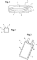
- a lithium-ion battery or accumulator usually comprises at least one electrochemical cell C consisting of an electrolyte constituent 1, impregnated in a separator making it possible to electrically isolate the electrodes, between a positive electrode or cathode 2 and a negative electrode or anode 3, a current collector 4 connected to the cathode 2, a current collector 5 connected to the anode 3 and finally, a package 6 arranged to contain the electrochemical cell and make it airtight and electrolyte inside the cell, while being traversed by a part of the current collectors 4, 5.
- the electrolyte component can be solid, liquid or gel.
- the constituent can comprise a separator made of polymer or microporous composite soaked with organic electrolyte (s) or of ionic liquid type which allows the displacement of the lithium ion from the cathode to the anode for a charge and vice versa for a discharge, which generates the current.
- the electrolyte is generally a mixture of organic solvents, for example carbonates to which is added a lithium salt typically LiPF6.
- lithiated iron phosphate LiFePO 4 lithiated cobalt oxide LiCoO 2 lithiated manganese oxide, optionally substituted, LiMn 2 O 4 or transition metal oxide, such as lamellar materials for
- the negative electrode or anode is very often made of carbon, graphite or Li 4 TiO 5 O 12 (titanate material), possibly possibly based on silicon or based on lithium, or based on tin and their alloys or formed composite based on silicon.
- This negative electrode like the positive electrode, can also contain electronic conductive additives as well as polymer additives which give it mechanical properties and electrochemical performance suitable for the lithium-ion battery application or its implementation process.
- the anode and the cathode of lithium insertion material can be deposited continuously according to a usual technique in the form of an active layer on a metal sheet or strip constituting a current collector.
- the current collector connected to the positive electrode is generally made of aluminum.
- the current collector connected to the negative electrode is generally made of copper, nickel, nickel-plated copper or aluminum.
- aluminum is used for current collectors common to positive and negative titanate electrodes Li 4 Ti 5 O 12 .
- Copper is rather for negative electrodes of graphite (Cgr), silicon (Si) or silicon composite (Si-C).
- a Li-ion battery or accumulator uses a couple of materials at the anode and at the cathode allowing it to operate at a voltage level, typically between 1.5 and 4.2 Volt.
- the packaging is then either flexible or rigid and in this latter case constitutes a sort of case.
- Rigid packaging (cases) are usually made from a metallic material, typically an aluminum alloy or stainless steel or a rigid polymer such as acrylonitrile butadiene styrene (ABS).
- a metallic material typically an aluminum alloy or stainless steel or a rigid polymer such as acrylonitrile butadiene styrene (ABS).
- ABS acrylonitrile butadiene styrene
- Flexible packaging is usually made from a multilayer composite material consisting of an aluminum foil covered by one or more polymer film (s) laminated by gluing.
- the polymer covering the aluminum is chosen from polyethylene (PE), propylene, polyamide (PA) or may be in the form of an adhesive layer made of polyester-polyurethane.
- PE polyethylene
- PA polyamide
- the company Showa Denko markets this type of composite material for use as packaging for batteries under the references NADR-0N25 / AL40 / CPP40 or N ° ADR-0N25 / AL40 / CPP80.
- the figure 3 illustrates this type of flexible packaging 6 which is arranged to isolate and seal the electrochemical cell C while being traversed by a part 40, 50 of two strips or tabs 4, 5, commonly known in English as "tab", forming the poles and which extend in the plane of the electrochemical cell.
- a flexible accumulator commonly called “Thin Film Battery”, is most often made up of a single electrochemical cell.
- the total thickness of the accumulator with its flexible packaging is generally less than 0.6 mm, which allows it to be folded according to a radius of curvature between 20 and 30 mm, which is a function of the dimensions and of the chemistry of the electrode materials, and this without affecting performance during the operation of the accumulator.
- the electrochemical cell (s) must be sealed against air humidity.
- the manufacturers use rivets or proceed by laser welding in the case of rigid packaging.
- a sealing tape In the case of flexible packaging, a sealing tape is used. It is generally based on a heat-fusible polymer around a metal outlet tab.
- the tab can be sold as such and is sized according to the flow of current which is linked to the total capacity of the battery. For cells with a capacity of less than 2 Ah, the tab has a width of 5 mm and a thickness of 0.5 mm.
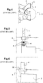
- the sealing tape is laminated glued to the tab and generally has a length of 10mm, a width of 5mm and a thickness of 0.3mm. An example of such an aluminum tab 4 is shown in figure 5 .
- reinforcements in polyolefin-based polymer 60 are provided to improve the heat sealing of the packaging 6 around the tabs 4, 5, and thus guarantee the sealing of the accumulator from the outside to the inside (water , oxygen, nitrogen %) and vice versa (electrolyte, gases due to electrochemical reactions ).
- the added tabs 4, 5 are fixed to the substrates forming the current collectors of the electrodes by ultrasonic welding.
- the tabs are generally made of nickel when they are fixed to a copper collector and aluminum when they are fixed to an aluminum collector.
- FIG. 5 An example of an aluminum tab 4 fixed on an aluminum collector is shown in figure 5 .
- a heat-fusible polymer tape 60 is laminated and glued to each main face of the tongue 4.
- the tabs with ribbon being initially supplied in the form of a continuous wound strip the length is cut according to the need for the metal tab 4.
- the connection external can also be provided directly by the current collecting substrates of the electrodes which are cut in the form of a tongue.
- This heat-fusible polymer tape 60 generally has a width of 5 mm and a thickness of 0.1 mm.
- the ribbon being initially supplied in the form of a continuous wound strip, the length is cut according to the need for the current-collecting substrate.
- the metal tab 4 typically made of aluminum, is either welded to the current collector 40 by welding points S, or is an integral part of the current collector 40.
- the patent EP2619832B1 in the name of the applicant discloses an electrode current collector for lithium battery, which is porous and is made of woven or nonwoven carbon fibers.
- the general aim of the invention is to meet this need at least in part.
- porous is meant here and within the framework of the invention, not airtight or to an electrolyte, in particular by the edge of the substrate.
- electrically conductive is meant here and within the framework of the invention, a conductivity greater than or equal to 1S / cm.
- the packaging of a system according to the invention can be rigid or flexible.
- the tongue is metallic, more preferably aluminum, copper or nickel. It has a thickness allowing this seam preferably between 10 ⁇ m and 200 ⁇ m. But we can also consider any other dense and sufficiently conductive material, such as certain sintered ceramics
- the electrically conductive wire is made of copper or aluminum, or of carbon or is metallized, such as for example metallized nylon.
- a number of stitches of 16 stitches / cm 2 is preferably recommended.
- a person skilled in the art will also size the different sections of current flow to guarantee a maximum of 5A / mm 2 , so as to avoid overheating.
- the diameter of the wire is between 0.3 and 2 mm for a carbon wire, between 0.1 and 0.5 mm for a copper wire and between 0.8 and 2 mm for an aluminum wire.
- the width of a sealing tape is preferably between 0.5 and 1 cm.
- the thickness of a sealing tape is preferably between 0.05 and 0.2 mm.
- the sealing tape is based on heat-fusible polymer.
- any other sealing material such as an adhesive, glass, provided that it is compatible with the electrolyte of the electrochemical system.
- the porous substrate is a substrate based on carbon fibers. It can advantageously be a nonwoven substrate. It is also possible to envisage, as a porous substrate, a metallic foam, such as a nickel, copper foam, etc.
- the substrate based on carbon fibers is a nonwoven produced from carbon fibers with a diameter preferably between 2 and 20 ⁇ m, preferably according to a form factor between diameter and length greater than 10, and preferably a density between 1.8 and 2.2.
- the carbon nonwoven substrate preferably has a thickness between 100 and 250 ⁇ m, preferably a density between 30 and 1100 mg / cm 3 , preferably a porosity between 50 and 98%.
- the substrate based on carbon fibers being porous, while preserving external connections also in substrate based on carbon fibers in the form of strip / bare tongue emerging from the current collector, the inventors have been able to note that the watertightness of a Li-ion battery was not guaranteed.
- the inventors have thought of using external metallic connections in the form of dense conductive tabs which are fixed to the carbon substrate by sewing, to guarantee flexibility and by providing them with a sealing tape to polymer base to ensure the tightness of the closure of the packaging on these dense tabs and no longer on porous tabs based on carbon fibers.
- the inventors then thought judiciously of securing the external metallic connections with the collecting substrate based on carbon fibers by sewing using a carbon wire and / or a metal wire, preferably made of Cu, Al ...
- the seam allows on the one hand to have a good electrical contact for the conduction of the current between the collector based on carbon fibers and an external metallic connection and on the other hand to reinforce the mechanical properties at the level of this connection. external.
- the preparation of the ink (active insertion material) of the electrode is carried out by mixing the constituents, namely the active material, the polymeric binder and the electronic conductor.
- the function of the polymer binder, PVdF or a water-soluble polymer, is to provide the mechanical properties of the electrodes while ensuring good contact between the electrolyte and the grains of the material.
- the electronic conductor often carbon black, improves the electronic conductivity of the electrodes.
- the electrode ink is then deposited on the carbon fiber current collector by a coating process which consists of pouring the ink onto the collector, thus forming a continuous electrode strip.
- deposition techniques such as printing, spraying, dispensing or the like which consists of depositing the ink in the form of patterns on the collector.
- deposition techniques such as printing, spraying, dispensing or the like which consists of depositing the ink in the form of patterns on the collector.
- continuous electrode patterns instead of a continuous strip.
- the continuous electrode patterns are preferably produced by printing technique from the ink prepared, more preferably by screen printing on current collecting substrates made of carbon nonwoven.
- Other printing techniques can be used such as flexography, rotogravure, inkjet, aerosol jet printing ...
- An important advantage of printing techniques is to be able to produce patterns of varied section (square, rectangular, round or more complex) and therefore allows to acquire a certain freedom on the design of the accumulator according to the invention.
- screen printing has the advantage of being able to deposit a larger quantity of ink in a single pass, which makes it possible to obtain high grammages and therefore high capacities.
- production rates are high, compared to coating, which is the conventional process used by battery manufacturers, typically a printing speed of 20 to 25 m / s for screen printing, compared to a speed of 10 to 15 m / s for coating.
- the continuous pattern of the electrode is deposited, it is dried. To do this, the solvent is evaporated by passing the electrode through a continuous or static oven in a ventilated oven.
- the electrodes are then calendered and then cut according to the pattern targeted in the application.
- the system comprises at least two tabs assembled to the porous substrate, at least one of the two tabs being intended to serve as an electrical connection with another electrochemical system to which the system integrating the electrode is connected.
- the accumulator can constitute a Li-ion accumulator, the electrode patterns being made of lithium insertion material.
- the fixing of a metal tab intended to form the external connection or pole of an accumulator is carried out.
- the fixing takes place by sewing by means of a carbon thread and / or a metallic thread and / or a metallic thread only.
- a ribbon in the form of a heat-fusible polymer layer preferably chosen from polyethylene (PE) or polypropylene (PP), is added between the packaging and the tabs around them.
- PE polyethylene
- PP polypropylene
- the packaging of an accumulator according to the invention preferably consists of a single flexible bag. It can be manufactured from a multilayer composite material consisting of an aluminum foil covered by one or more polymer film (s) laminated by gluing.
- the polymer covering the aluminum can be chosen from polyethylene (PE), propylene, polyamide (PA) or can be in the form of an adhesive layer made of polyester-polyurethane.
- PE polyethylene
- PA polyamide
- the company Showa Denko markets this type of composite material for use as packaging for batteries under the references NADR-0N25 / AL40 / CPP40 or N ° ADR-0N25 / AL40 / CPP80.
- the flexible bag according to the invention is advantageously based on an aluminized multilayer film, airtight.
- the accumulator according to the invention can be a Li-ion accumulator, the electrode patterns being made of lithium insertion material.
- lithium insertion material electrode is meant here and within the framework of the invention, an electrode pattern comprising at least one lithium insertion material and at least one polymer binder.
- the electrode pattern may further comprise an electronic conductor, for example carbon nanofibress, carbon fiber nanotubes or carbon black.
- lithium insertion material in particular for the positive electrode patterns, is meant here and within the framework of the invention, a material chosen from lithiated oxides comprising manganese of spinel structure, lithiated oxides of lamellar structure and mixtures thereof, lithiated oxides with polyanionic frameworks of formula LiM y (XO z ) n with M representing an element chosen from Mn, Fe, Co, Ni, Cu, Mg, Zn, V, Ca, Sr, Ba, Ti, Al, Si, B and Mo, X representing an element chosen from P, Si, Ge, S and As, y, z and n being positive integers.
- M an element chosen from Mn, Fe, Co, Ni, Cu, Mg, Zn, V, Ca, Sr, Ba, Ti, Al, Si, B and Mo
- X representing an element chosen from P, Si, Ge, S and As, y, z and n being positive integers.
- lithium insertion material in particular for the negative electrode patterns, is also meant a material chosen from: titanium oxide, lithiated or not, for example Li 4 Ti 5 O 12 or TiO 2 , graphite, silicon , or silicon composite. More particularly, the material of the negative electrode patterns can be chosen from carbon materials, non-lithiated titanium oxides and their derivatives and lithiated titanium oxides such as Li 4 Ti 5 O 12 and their derivatives and a mixture of those -this.
- lithiumated derivative is meant here and within the framework of the invention, compounds of formula Li (4-x1) M x1 Ti 5 O 12 and Li 4 Ti (5-y1) N y1 O 12 , where x1 and y1 are respectively between 0 and 0.2 and M and N are respectively chemical elements chosen from Na, K, Mg, Nb, Al, Ni, Co, Zr, Cr, Mn, Fe, Cu, Zn, Si and Mo.
- non-lithiated derivative is meant here and within the framework of the invention, Ti (5-y1) N y1 O 12 , with y1 between 0 and 0.2 and N is a chemical element chosen from Na, K , Mg, Nb, Al, Ni, Co, Zr, Cr, Mn, Fe, Cu, Zn, Si and Mo.
- the anodes are made of graphite and the cathodes of LiNi 0.8 Co 0.15 Al 0.05 O 2 (NCA).
- NCA LiNi 0.8 Co 0.15 Al 0.05 O 2
- separatator is meant here and within the framework of the invention, an electrical insulator, ionic conductor formed by at least one polymeric material.
- the separator is preferably a monolayer or multilayer polymer microporous film based on PP or / and PE polyolefin. Each separator film is cut according to the desired pattern by a mechanical or laser process.
- the separator can be implemented directly on the electrode patterns (positive or negative) by printing, preferably screen printing, from a polymer solution.
- the polymer is dissolved in a solvent, or in a solvent / non-solvent mixture in the case of a phase inversion process.
- the polymer solution is deposited on the electrode patterns in the form of a thin layer, then the solvent is evaporated by passing the electrode through a continuous or static oven.
- the thin layer of the electrolytic component can be porous, dense or gelled in the presence of the electrolyte.
- the thickness of the polymer layer is preferably between 5 and 40 ⁇ m.
- separators can be envisaged as composites consisting of a very thin polymer layer, of the order of 15 ⁇ m.
- the polymer used can be PET or polyethylene terephthalate.
- This very thin sheet of polymer can then be covered with grains of alumina (Al 2 O 3 ) and silica (SiO 2 ) ceramics. Mention may be made here of the separator sold under the name SEPARION by the company EVONIK.
- separators based on polymers reinforced by glass fibers for mechanical characteristics. These separators are nonwovens because the glass fibers are only mixed together randomly.
- ceramic separators comprising in particular alumina, which has the advantage of having a retarding effect on thermal runaway.
- the electrolyte according to the invention can be a liquid formed by a mixture of carbonate and at least one lithium salt.
- lithium salt is preferably meant a salt chosen from LiPF 6 , LiClO 4 , LiBF 4 and LiAsF 6 .
- the electrolyte can comprise one or more ionic liquid, based on lithium ions, namely a salt consisting of lithium cations, complexed with inorganic or organic anions, which has the property of being in the liquid state at ambient temperature.
- An ionic liquid depending on the nature of the anion, can be hydrophilic or hydrophobic. Examples of ionic liquids that may be mentioned include ionic liquids based on hydrophobic anions such as trifluoromethanesulfonate (CF 3 SO 3 ), bis (trifluoromethanesulfonate imide [(CF 3 SO 2 ) 2 N] and tris (trifluoromethanesulfonate) methide [(CF 3 SO 2 ) 3 C].
- each negative electrode pattern is greater than the area of each positive electrode pattern. It is thus ensured that all the metal ions of the positive insertion material, such as the Li + ions in a lithium accumulator, can migrate towards the negative electrode and thus become intercalated in the structure. Besides the alignment of the positive electrode patterns with those of the negative electrode, it is also possible to increase the surface of the negative electrode patterns compared to those of the positive electrode. This can correspond to a strip of active material, added on each side of each negative electrode pattern. An added strip can typically have a width of 1mm.
- the invention also relates to a battery comprising a plurality of accumulators as above, two adjacent accumulators being electrically connected to each other by at least one electrical connecting strip made of porous conductive substrate, one end of which is linked to a tab dense of a negative or positive electrode of one of the two accumulators and the other end is linked to a dense tab of a respectively negative or positive electrode of the other of the two accumulators, the connection between the strip and each of the tongues being produced according to at least one electrically conductive junction obtained by sewing by means of at least one metallic and / or carbon wire.
- two adjacent accumulators are connected to each other in electrical parallel by two electrical connecting strips, one of which connects the positive electrodes of the two accumulators to one another and the other connects the negative electrodes of the two accumulators to each other.
- two adjacent accumulators are connected together in electrical series by a single electrical connecting strip.
- the battery can advantageously comprise at least one mechanical connection strip made of a porous conductive substrate, each of the ends of which is linked to a dense mechanical connection tab which is not linked to a negative or positive electrode of the accumulators, the connection between the strip of mechanical connection and each of the mechanical connection tabs being produced according to at least one junction obtained by sewing by means of at least one wire.
- the general use of the accumulator is to supply electrically any electronic device capable of deforming in order to be shaped with a constrained location of shapes and / or space.
- RFID type sensors or antennas for “ Radio Frequency Identification ” intended to be installed housed in the passenger compartment of a motor vehicle, or in the smallest recess available in the vehicle, for communication of information.
- An accumulator according to the invention also relates to the field of flexible electronics with applications such as sensors for intelligent clothing, flexible type screens, electronic papers, etc. where the final object is subjected to constraints. of repeated deformations.
- the positive electrode 2 firstly comprises a substrate based on carbon fibers 2S forming a current collector and supporting, on one of its main faces, a continuous pattern of active material for positive insertion of metal ion 2I ( figure 7 ).
- the negative electrode 3 also comprises a substrate based on carbon fibers 3S forming a current collector and supporting, on one of its main faces, a continuous pattern of active material for negative insertion of metal ion 3I ( figure 9 ).
- the carbon fibers from which a 2S or 3S substrate is made can have a diameter of approximately 7 ⁇ m and a density of 2.
- a 2S or 3S substrate based on these carbon fibers can thus have a thickness of 150 ⁇ m, a density of 628 mg / cm 3 and a porosity of 69%.
- the positive electrode 2 comprises as active material LiNiCoAlO 2 , designated by NCA ( figure 7 ) and the negative electrode 3 is based on graphite ( figure 9 ).
- a metal tab 4, 5 is made with the substrate based on carbon fibers 2S, 3S respectively of the positive electrode 2 and the negative electrode 3.
- an aluminum strip 4, 20 ⁇ m thick is used for the positive electrode NCA 2 and a copper strip 5, thick 10 ⁇ m, for the negative graphite electrode 3.
- metal tabs 4, 5 have been fixed to the collecting substrate based on carbon fibers 2S, 3S by means of sewing stitches produced manually using a needle and a carbon thread 7, diameter 1mm. Sewing can use the conventional sewing machine techniques of metal threads. With regard to the knots for finishing the seam, once the tongue / felt joint in C has been made, it is possible to implement a conventional technique of stopping in seam, for example passing in reverse at almost the same place.
- the stitch patterns can be diverse and varied, such as straight stitch, zigzag stitch ...
- an electrically insulating separator film 1, of the polymer microporous type is arranged in contact with each of the electrode patterns 2I, 3I supported respectively by the substrate based on carbon fibers 2S and the substrate based on carbon fibers. 3S.
- a sealing tape 60 based on heat-fusible polymer is then placed on either side of the metal tabs of aluminum 4 and copper 5.
- a flexible package 6, impermeable to the electrolyte and to air, is arranged to contain the positive 2 and negative 3 electrodes and the microporous separating film 1, with sealing while being traversed by the tongues 4, 5 forming the poles of the accumulator.
- the flexible packaging 6 consists of a multilayer film aluminized on the outside.
- the flexible packaging 6 is then closed.
- the fourth side is kept open in order to activate the accumulator which consists in filling the interior of the packaging container thus formed with electrolyte. After activation of the accumulator, this fourth side is also thermally sealed.
- a plurality of accumulators according to the invention can be assembled in series or in electrical parallel with one another in order to constitute a final battery.
- the final battery comprises two output poles or connections at the ends, one 5 connected to the negative electrode 3 on one of the end accumulators A1 and the other 4 connected to the positive electrode 2 on the other of the end accumulators A3.
- the accumulators A1, A2, A3 are electrically connected to each other by the metal tabs / poles 4, 5 which are sewn or woven on the substrates made of carbon nonwoven 2S, 3S as well as by electrical connection strips 8 also based on carbon fibers.
- One of the ends of a strip 8 is connected to a positive metal tab 4 and the other of the ends of the strip 8 is connected to a negative metal tab 5.
- These connections are also made by carbon-metal junctions J by sewing a carbon or metal wire 7 as explained above.
- a mechanical connection strip 9 is advantageously added between two adjacent accumulators A1-A2, A2-A3.
- Each mechanical connection strip 9 is based on carbon fibers, each of the ends of which is linked to a metal tab 4, 5 also by a metal-carbon junction J. Each strip 9 is arranged parallel to an electrical connection strip 8 connecting the two positive 4 and negative 5 poles.
- the attachment points of a mechanical connection strip 9 to the flexible packaging 6 of two adjacent accumulators A1-A2, A2-A3 each consist of a sealing tape 60 supported on either side of a tongue metallic 4, 5 as before.
- the final battery comprises two output poles or connections at the ends, one 5 connected to the negative electrode 3 on one of the end accumulators A1 and the other 4 connected to the positive electrode 2 on the same end accumulator A1.
- two adjacent accumulators A1-A2, A2-A3 are electrically connected by two electrical connection strips 8 based on carbon fibers.
- One of these two bands 8 connects the positive electrodes 2 of the two accumulators A1-A2, A2-A3 to each other and the other 8 connects the negative electrodes 3 of the two accumulators A1-A2, A2-A3 to each other.
Landscapes
- Chemical & Material Sciences (AREA)
- Chemical Kinetics & Catalysis (AREA)
- Electrochemistry (AREA)
- General Chemical & Material Sciences (AREA)
- Engineering & Computer Science (AREA)
- Materials Engineering (AREA)
- Inorganic Chemistry (AREA)
- Manufacturing & Machinery (AREA)
- Secondary Cells (AREA)
- Battery Electrode And Active Subsutance (AREA)
- Cell Electrode Carriers And Collectors (AREA)
Claims (15)
- Dichtes elektrochemisches System, welches umfasst;- eine Hülle;- ein elektrisch leitendes und poröses Substrat (2S, 3S), das einen Stromkollektor bildet und auf wenigstens einer seiner Hauptflächen wenigstens eine durchgehende Struktur von aktivem Material einer Elektrode (2I, 3I) trägt; wobei das poröse Substrat vorzugsweise auf Carbonfasern basiert;- wenigstens eine elektrisch leitende und kompakte Zunge (4, 5), die mit dem Substrat über wenigstens eine elektrisch leitende Verbindungsstelle verbunden ist, die durch Nähen mittels wenigstens eines elektrisch leitenden Drahtes erhalten wird, wobei die Zunge auf jeder ihrer Hauptflächen wenigstens ein Dichtungsband trägt, das mit der Hülle versiegelt ist, um den dichten Verschluss derselben zu garantieren.
- System nach Anspruch 1, wobei der Draht metallisch ist, vorzugsweise aus Kupfer oder aus Aluminium, oder aus Kohlenstoff besteht oder nur metallisiert ist, vorzugsweise aus metallisiertem Nylon.
- System nach einem der vorhergehenden Ansprüche, wobei die Dicke der Zunge zwischen 10 und 200 µm liegt.
- System nach einem der vorhergehenden Ansprüche, wobei die Anzahl der Nähstiche mindestens 16 Nähstiche/cm2 beträgt.
- System nach einem der vorhergehenden Ansprüche, wobei die Zunge metallisch ist, vorzugsweise aus Aluminium, aus Kupfer oder aus Nickel.
- System nach einem der vorhergehenden Ansprüche, wobei der Metalldraht aus Kupfer oder aus Aluminium besteht.
- System nach einem der vorhergehenden Ansprüche, wobei der Durchmesser des Drahtes zwischen 0,3 und 2 mm für einen Kohlenstoffdraht, zwischen 0,1 und 0,5 mm für einen Kupferdraht und zwischen 0,8 und 2 mm für einen Aluminiumdraht liegt.
- System nach einem der vorhergehenden Ansprüche, wobei die Breite eines Dichtungsbandes zwischen 0,5 und 1 cm liegt, wobei die Dicke eines Dichtungsbandes vorzugsweise zwischen 0,05 und 0,2 mm liegt.
- System nach einem der vorhergehenden Ansprüche, welches wenigstens zwei Zungen umfasst, die mit dem porösen Substrat zusammengebaut sind, wobei wenigstens eine der zwei Zungen dazu bestimmt ist, als elektrische Verbindung mit einem anderen elektrochemischen System zu dienen, mit welchem das System, in das die Elektrode integriert ist, verbunden ist.
- Elektrochemischer Metallionen-Akkumulator (A), welcher aus einem dichten elektrochemischen System nach einem der vorhergehenden Ansprüche gebildet ist und einen Stapel der folgenden Elemente umfasst:- wenigstens eine negative Elektrode;- wenigstens eine positive Elektrode;- wenigstens einen elektrisch isolierenden Separatorfilm, in den ein Elektrolyt integriert ist und der in Kontakt mit der negativen Elektrodenstruktur und der positiven Elektrodenstruktur angeordnet ist;- eine Hülle (6), die dafür ausgelegt ist, die negative und die positive Elektrode und den Separatorfilm zu enthalten, mit Abdichtung, wobei sie zugleich von einem ersten und einem zweiten Pol des Akkumulators durchquert wird, die jeweils aus der leitenden Zunge bestehen, die an das poröse Substrat der negativen Elektrode bzw. der positiven Elektrode genäht ist, wobei die Dichtungsbänder (60) der negativen und der positiven Elektrode mit der Hülle (6) heißversiegelt sind.
- Batterie, welche mehrere Akkumulatoren nach Anspruch 10 umfasst, wobei zwei benachbarte Akkumulatoren durch wenigstens einen aus porösem leitendem Substrat hergestellten Streifen zur elektrischen Verbindung elektrisch miteinander verbunden sind, von dem ein Ende mit einer kompakten Zunge einer negativen oder positiven Elektrode eines der Akkumulatoren verbunden ist und das andere Ende mit einer kompakten Zunge einer negativen bzw. positiven Elektrode des anderen der zwei Akkumulatoren verbunden ist, wobei die Verbindung zwischen dem Streifen und jeder der Zungen über wenigstens eine elektrisch leitende Verbindungsstelle hergestellt ist, die durch Nähen mittels wenigstens eines Metall- und/oder Kohlenstoffdrahtes erhalten wird.
- Batterie nach Anspruch 11, wobei zwei benachbarte Akkumulatoren durch zwei Streifen zur elektrischen Verbindung elektrisch zueinander parallelgeschaltet sind, von denen einer die positiven Elektroden der zwei Akkumulatoren miteinander verbindet und der andere die negativen Elektroden der zwei Akkumulatoren miteinander verbindet.
- Batterie nach Anspruch 11, wobei zwei benachbarte Akkumulatoren durch nur einen Streifen zur elektrischen Verbindung elektrisch zueinander in Reihe geschaltet sind.
- Batterie nach Anspruch 13, welche außerdem wenigstens einen Streifen zur mechanischen Verbindung aus porösem leitendem Substrat umfasst, von dem jedes der Enden mit einer kompakten Zunge zur mechanischen Verbindung verbunden ist, welche nicht mit einer negativen oder positiven Elektrode der Akkumulatoren verbunden ist, wobei die Verbindung zwischen dem Streifen zur mechanischen Verbindung und jeder der Zungen zur mechanischen Verbindung über wenigstens eine Verbindungsstelle hergestellt ist, die durch Nähen mittels wenigstens eines Drahtes erhalten wird.
- Verfahren zur Herstellung eines dichten elektrochemischen Systems, welches die folgenden Schritte umfasst:a/ Erzielung einer durchgehenden Struktur von aktivem Elektrodenmaterial auf einem elektrisch leitenden und porösen Substrat, das einen Stromkollektor bildet; wobei das poröse Substrat vorzugsweise auf Carbonfasern basiert;b/ Herstellung wenigstens einer elektrisch leitenden Verbindungsstelle zwischen wenigstens einer elektrisch leitenden und kompakten Zunge und dem Substrat durch Nähen mittels wenigstens eines elektrisch leitenden Drahtes;c/ Herstellung, auf jeder der Hauptflächen der Zunge, wenigstens eines Dichtungsbandes, das für den dichten Verschluss der Hülle bestimmt ist;d/ Versiegelung zwischen Dichtungsband und Hülle.
Applications Claiming Priority (1)
| Application Number | Priority Date | Filing Date | Title |
|---|---|---|---|
| FR1761019A FR3073983B1 (fr) | 2017-11-21 | 2017-11-21 | Collecteur de courant poreux avec languette de connexion electrique dense pour systeme electrochimique etanche |
Publications (2)
| Publication Number | Publication Date |
|---|---|
| EP3486971A1 EP3486971A1 (de) | 2019-05-22 |
| EP3486971B1 true EP3486971B1 (de) | 2020-05-20 |
Family
ID=61750243
Family Applications (1)
| Application Number | Title | Priority Date | Filing Date |
|---|---|---|---|
| EP18205500.4A Active EP3486971B1 (de) | 2017-11-21 | 2018-11-09 | Poröser stromkollektor mit dichter elektrischer anschlusszunge für dichtes elektrochemisches system |
Country Status (3)
| Country | Link |
|---|---|
| US (1) | US20190157683A1 (de) |
| EP (1) | EP3486971B1 (de) |
| FR (1) | FR3073983B1 (de) |
Cited By (1)
| Publication number | Priority date | Publication date | Assignee | Title |
|---|---|---|---|---|
| EP4243127A1 (de) | 2022-03-09 | 2023-09-13 | Commissariat à l'énergie atomique et aux énergies alternatives | Poröser stromkollektor mit durch thermische abdichtung eines heissschmelzpolymers an einer dichten elektrischen anschlusslasche für ein abgedichtetes elektrochemisches system. |
Families Citing this family (3)
| Publication number | Priority date | Publication date | Assignee | Title |
|---|---|---|---|---|
| DE102018216002A1 (de) * | 2018-09-20 | 2020-03-26 | Robert Bosch Gmbh | Verfahren zur Herstellung einer Batteriezelle |
| US11456483B2 (en) | 2019-03-04 | 2022-09-27 | The Mitre Corporation | Carbon fiber battery electrodes with ionic liquid and gel electrolytes |
| CN113013377A (zh) * | 2021-04-20 | 2021-06-22 | 珠海冠宇电池股份有限公司 | 电池 |
Family Cites Families (6)
| Publication number | Priority date | Publication date | Assignee | Title |
|---|---|---|---|---|
| CN102047488A (zh) * | 2008-03-07 | 2011-05-04 | 莱登能源公司 | 具有连接片的电化学电池 |
| JP2011523765A (ja) * | 2008-05-29 | 2011-08-18 | ライデン エナジー インコーポレイテッド | イオン液体電解質を含む電気化学セル |
| DE102012000819A1 (de) * | 2012-01-17 | 2013-07-18 | Li-Tec Battery Gmbh | Elektrochemischer Energiespeicher oder Energiewandler |
| CN107004783B (zh) * | 2014-12-08 | 2019-11-12 | 株式会社Lg化学 | 具有改善的输出特性的二次电池 |
| FR3041818B1 (fr) * | 2015-09-28 | 2017-09-08 | Commissariat Energie Atomique | Procede de fixation entre un collecteur metallique et un feutre de carbone d'une batterie et batterie realisee par le procede |
| FR3044831B1 (fr) * | 2015-12-02 | 2023-01-20 | Commissariat Energie Atomique | Procede de regeneration de capacite d'un accumulateur electrochimique metal-ion, accumulateur associe |
-
2017
- 2017-11-21 FR FR1761019A patent/FR3073983B1/fr not_active Expired - Fee Related
-
2018
- 2018-11-09 EP EP18205500.4A patent/EP3486971B1/de active Active
- 2018-11-20 US US16/196,009 patent/US20190157683A1/en not_active Abandoned
Non-Patent Citations (1)
| Title |
|---|
| None * |
Cited By (2)
| Publication number | Priority date | Publication date | Assignee | Title |
|---|---|---|---|---|
| EP4243127A1 (de) | 2022-03-09 | 2023-09-13 | Commissariat à l'énergie atomique et aux énergies alternatives | Poröser stromkollektor mit durch thermische abdichtung eines heissschmelzpolymers an einer dichten elektrischen anschlusslasche für ein abgedichtetes elektrochemisches system. |
| FR3133485A1 (fr) | 2022-03-09 | 2023-09-15 | Commissariat A L'energie Atomique Et Aux Energies Alternatives | Collecteur de courant poreux avec jonction obtenue par scellage thermique d’un polymère thermofusible à une languette de connexion électrique dense pour système électrochimique étanche. |
Also Published As
| Publication number | Publication date |
|---|---|
| US20190157683A1 (en) | 2019-05-23 |
| EP3486971A1 (de) | 2019-05-22 |
| FR3073983B1 (fr) | 2019-11-15 |
| FR3073983A1 (fr) | 2019-05-24 |
Similar Documents
| Publication | Publication Date | Title |
|---|---|---|
| EP2984697B1 (de) | Elektrochemische lithiumspeicherbatterie mit einem gehäuse mit verbesserter wärmeableitung, batteriepack und zugehöriges herstellungsverfahren | |
| EP1841001B1 (de) | Bipolar-batterie | |
| EP3252862B1 (de) | Sekundärbatterie | |
| JP5483877B2 (ja) | 交互に上下に積層され固定されたセパレータおよび電極から成るLi電池用積層体 | |
| KR101623674B1 (ko) | 비수전해질 이차 전지 | |
| EP2870655B1 (de) | Stromabnehmer mit integrierter dichtungsvorrichtung, bipolare batterie mit solch einem stromabnehmer | |
| JP5625123B2 (ja) | 遠心力を用いて二次電池を脱気する方法 | |
| EP3012898B1 (de) | Sekundärbatterie und elektrodenherstellverfahren | |
| EP3000141B1 (de) | Bipolare li-ionen-batterie mit verbesserter abdichtung und zugehöriges verfahren zur herstellung | |
| JP5631537B2 (ja) | 双極型二次電池 | |
| FR2961637A1 (fr) | Collecteur de courant avec moyens d'etancheite integres, batterie bipolaire comprenant un tel collecteur | |
| EP3649694B1 (de) | Verfahren zur herstellung eines elektrochemischen bündels einer metall-ionenbatterie mittels einer gelpolymerelektrolytmembran und zugehörige batterien | |
| EP2904654B1 (de) | Bipolare batterie mit einem stromkollektor mit eingebauter dichtung und verfahren zur herstellung solch einer batterie | |
| FR3073983B1 (fr) | Collecteur de courant poreux avec languette de connexion electrique dense pour systeme electrochimique etanche | |
| CN111527627A (zh) | 制造负极的方法以及由此获得的负极 | |
| EP3346522B1 (de) | Elektrochemischer akkumulator mit ebenem aufbau, der teilweise durch druckverfahren erzielt wird | |
| KR102826110B1 (ko) | 용해 온도가 다른 바인더를 포함하는 분리막 및 이의 제조방법 | |
| EP2539952B1 (de) | Hochleistungs-lithiumionenakkumulator | |
| EP4243127A1 (de) | Poröser stromkollektor mit durch thermische abdichtung eines heissschmelzpolymers an einer dichten elektrischen anschlusslasche für ein abgedichtetes elektrochemisches system. | |
| JP4424079B2 (ja) | ポリマー電池、ポリマー電池の製造方法、組電池、および、これらを搭載した車両 | |
| EP3482432B1 (de) | Metall-ion akkumulator mit hohe kapazität, wessen flexibilität für eine hohe gleichförmichkeit dient | |
| EP4175014B1 (de) | Stromabnehmer eines instrumentierungselements eines elektrochemischen systems mit durch wärmeversiegelung eines heissschmelzpolymers an einem elektrisch leitenden band gestützten elektrisch leitenden band. | |
| EP2826082B1 (de) | Leichtgewichtiger elektrochemischer speicher auf li-ionen-basis |
Legal Events
| Date | Code | Title | Description |
|---|---|---|---|
| PUAI | Public reference made under article 153(3) epc to a published international application that has entered the european phase |
Free format text: ORIGINAL CODE: 0009012 |
|
| STAA | Information on the status of an ep patent application or granted ep patent |
Free format text: STATUS: REQUEST FOR EXAMINATION WAS MADE |
|
| 17P | Request for examination filed |
Effective date: 20181109 |
|
| AK | Designated contracting states |
Kind code of ref document: A1 Designated state(s): AL AT BE BG CH CY CZ DE DK EE ES FI FR GB GR HR HU IE IS IT LI LT LU LV MC MK MT NL NO PL PT RO RS SE SI SK SM TR |
|
| AX | Request for extension of the european patent |
Extension state: BA ME |
|
| GRAP | Despatch of communication of intention to grant a patent |
Free format text: ORIGINAL CODE: EPIDOSNIGR1 |
|
| STAA | Information on the status of an ep patent application or granted ep patent |
Free format text: STATUS: GRANT OF PATENT IS INTENDED |
|
| INTG | Intention to grant announced |
Effective date: 20200109 |
|
| GRAS | Grant fee paid |
Free format text: ORIGINAL CODE: EPIDOSNIGR3 |
|
| GRAA | (expected) grant |
Free format text: ORIGINAL CODE: 0009210 |
|
| STAA | Information on the status of an ep patent application or granted ep patent |
Free format text: STATUS: THE PATENT HAS BEEN GRANTED |
|
| AK | Designated contracting states |
Kind code of ref document: B1 Designated state(s): AL AT BE BG CH CY CZ DE DK EE ES FI FR GB GR HR HU IE IS IT LI LT LU LV MC MK MT NL NO PL PT RO RS SE SI SK SM TR |
|
| REG | Reference to a national code |
Ref country code: GB Ref legal event code: FG4D Free format text: NOT ENGLISH |
|
| REG | Reference to a national code |
Ref country code: CH Ref legal event code: EP |
|
| REG | Reference to a national code |
Ref country code: DE Ref legal event code: R096 Ref document number: 602018004760 Country of ref document: DE |
|
| REG | Reference to a national code |
Ref country code: AT Ref legal event code: REF Ref document number: 1273213 Country of ref document: AT Kind code of ref document: T Effective date: 20200615 |
|
| REG | Reference to a national code |
Ref country code: LT Ref legal event code: MG4D |
|
| REG | Reference to a national code |
Ref country code: NL Ref legal event code: MP Effective date: 20200520 |
|
| PG25 | Lapsed in a contracting state [announced via postgrant information from national office to epo] |
Ref country code: LT Free format text: LAPSE BECAUSE OF FAILURE TO SUBMIT A TRANSLATION OF THE DESCRIPTION OR TO PAY THE FEE WITHIN THE PRESCRIBED TIME-LIMIT Effective date: 20200520 Ref country code: FI Free format text: LAPSE BECAUSE OF FAILURE TO SUBMIT A TRANSLATION OF THE DESCRIPTION OR TO PAY THE FEE WITHIN THE PRESCRIBED TIME-LIMIT Effective date: 20200520 Ref country code: GR Free format text: LAPSE BECAUSE OF FAILURE TO SUBMIT A TRANSLATION OF THE DESCRIPTION OR TO PAY THE FEE WITHIN THE PRESCRIBED TIME-LIMIT Effective date: 20200821 Ref country code: NO Free format text: LAPSE BECAUSE OF FAILURE TO SUBMIT A TRANSLATION OF THE DESCRIPTION OR TO PAY THE FEE WITHIN THE PRESCRIBED TIME-LIMIT Effective date: 20200820 Ref country code: IS Free format text: LAPSE BECAUSE OF FAILURE TO SUBMIT A TRANSLATION OF THE DESCRIPTION OR TO PAY THE FEE WITHIN THE PRESCRIBED TIME-LIMIT Effective date: 20200920 Ref country code: PT Free format text: LAPSE BECAUSE OF FAILURE TO SUBMIT A TRANSLATION OF THE DESCRIPTION OR TO PAY THE FEE WITHIN THE PRESCRIBED TIME-LIMIT Effective date: 20200921 Ref country code: SE Free format text: LAPSE BECAUSE OF FAILURE TO SUBMIT A TRANSLATION OF THE DESCRIPTION OR TO PAY THE FEE WITHIN THE PRESCRIBED TIME-LIMIT Effective date: 20200520 |
|
| REG | Reference to a national code |
Ref country code: DE Ref legal event code: R079 Ref document number: 602018004760 Country of ref document: DE Free format text: PREVIOUS MAIN CLASS: H01M0002260000 Ipc: H01M0050531000 |
|
| PG25 | Lapsed in a contracting state [announced via postgrant information from national office to epo] |
Ref country code: HR Free format text: LAPSE BECAUSE OF FAILURE TO SUBMIT A TRANSLATION OF THE DESCRIPTION OR TO PAY THE FEE WITHIN THE PRESCRIBED TIME-LIMIT Effective date: 20200520 Ref country code: RS Free format text: LAPSE BECAUSE OF FAILURE TO SUBMIT A TRANSLATION OF THE DESCRIPTION OR TO PAY THE FEE WITHIN THE PRESCRIBED TIME-LIMIT Effective date: 20200520 Ref country code: LV Free format text: LAPSE BECAUSE OF FAILURE TO SUBMIT A TRANSLATION OF THE DESCRIPTION OR TO PAY THE FEE WITHIN THE PRESCRIBED TIME-LIMIT Effective date: 20200520 Ref country code: BG Free format text: LAPSE BECAUSE OF FAILURE TO SUBMIT A TRANSLATION OF THE DESCRIPTION OR TO PAY THE FEE WITHIN THE PRESCRIBED TIME-LIMIT Effective date: 20200820 |
|
| REG | Reference to a national code |
Ref country code: AT Ref legal event code: MK05 Ref document number: 1273213 Country of ref document: AT Kind code of ref document: T Effective date: 20200520 |
|
| PG25 | Lapsed in a contracting state [announced via postgrant information from national office to epo] |
Ref country code: AL Free format text: LAPSE BECAUSE OF FAILURE TO SUBMIT A TRANSLATION OF THE DESCRIPTION OR TO PAY THE FEE WITHIN THE PRESCRIBED TIME-LIMIT Effective date: 20200520 Ref country code: NL Free format text: LAPSE BECAUSE OF FAILURE TO SUBMIT A TRANSLATION OF THE DESCRIPTION OR TO PAY THE FEE WITHIN THE PRESCRIBED TIME-LIMIT Effective date: 20200520 |
|
| PG25 | Lapsed in a contracting state [announced via postgrant information from national office to epo] |
Ref country code: RO Free format text: LAPSE BECAUSE OF FAILURE TO SUBMIT A TRANSLATION OF THE DESCRIPTION OR TO PAY THE FEE WITHIN THE PRESCRIBED TIME-LIMIT Effective date: 20200520 Ref country code: IT Free format text: LAPSE BECAUSE OF FAILURE TO SUBMIT A TRANSLATION OF THE DESCRIPTION OR TO PAY THE FEE WITHIN THE PRESCRIBED TIME-LIMIT Effective date: 20200520 Ref country code: SM Free format text: LAPSE BECAUSE OF FAILURE TO SUBMIT A TRANSLATION OF THE DESCRIPTION OR TO PAY THE FEE WITHIN THE PRESCRIBED TIME-LIMIT Effective date: 20200520 Ref country code: CZ Free format text: LAPSE BECAUSE OF FAILURE TO SUBMIT A TRANSLATION OF THE DESCRIPTION OR TO PAY THE FEE WITHIN THE PRESCRIBED TIME-LIMIT Effective date: 20200520 Ref country code: ES Free format text: LAPSE BECAUSE OF FAILURE TO SUBMIT A TRANSLATION OF THE DESCRIPTION OR TO PAY THE FEE WITHIN THE PRESCRIBED TIME-LIMIT Effective date: 20200520 Ref country code: AT Free format text: LAPSE BECAUSE OF FAILURE TO SUBMIT A TRANSLATION OF THE DESCRIPTION OR TO PAY THE FEE WITHIN THE PRESCRIBED TIME-LIMIT Effective date: 20200520 Ref country code: EE Free format text: LAPSE BECAUSE OF FAILURE TO SUBMIT A TRANSLATION OF THE DESCRIPTION OR TO PAY THE FEE WITHIN THE PRESCRIBED TIME-LIMIT Effective date: 20200520 Ref country code: DK Free format text: LAPSE BECAUSE OF FAILURE TO SUBMIT A TRANSLATION OF THE DESCRIPTION OR TO PAY THE FEE WITHIN THE PRESCRIBED TIME-LIMIT Effective date: 20200520 |
|
| REG | Reference to a national code |
Ref country code: DE Ref legal event code: R097 Ref document number: 602018004760 Country of ref document: DE |
|
| PG25 | Lapsed in a contracting state [announced via postgrant information from national office to epo] |
Ref country code: SK Free format text: LAPSE BECAUSE OF FAILURE TO SUBMIT A TRANSLATION OF THE DESCRIPTION OR TO PAY THE FEE WITHIN THE PRESCRIBED TIME-LIMIT Effective date: 20200520 Ref country code: PL Free format text: LAPSE BECAUSE OF FAILURE TO SUBMIT A TRANSLATION OF THE DESCRIPTION OR TO PAY THE FEE WITHIN THE PRESCRIBED TIME-LIMIT Effective date: 20200520 |
|
| PLBE | No opposition filed within time limit |
Free format text: ORIGINAL CODE: 0009261 |
|
| STAA | Information on the status of an ep patent application or granted ep patent |
Free format text: STATUS: NO OPPOSITION FILED WITHIN TIME LIMIT |
|
| 26N | No opposition filed |
Effective date: 20210223 |
|
| PG25 | Lapsed in a contracting state [announced via postgrant information from national office to epo] |
Ref country code: SI Free format text: LAPSE BECAUSE OF FAILURE TO SUBMIT A TRANSLATION OF THE DESCRIPTION OR TO PAY THE FEE WITHIN THE PRESCRIBED TIME-LIMIT Effective date: 20200520 |
|
| REG | Reference to a national code |
Ref country code: DE Ref legal event code: R119 Ref document number: 602018004760 Country of ref document: DE |
|
| PG25 | Lapsed in a contracting state [announced via postgrant information from national office to epo] |
Ref country code: MC Free format text: LAPSE BECAUSE OF FAILURE TO SUBMIT A TRANSLATION OF THE DESCRIPTION OR TO PAY THE FEE WITHIN THE PRESCRIBED TIME-LIMIT Effective date: 20200520 |
|
| PG25 | Lapsed in a contracting state [announced via postgrant information from national office to epo] |
Ref country code: LU Free format text: LAPSE BECAUSE OF NON-PAYMENT OF DUE FEES Effective date: 20201109 |
|
| REG | Reference to a national code |
Ref country code: BE Ref legal event code: MM Effective date: 20201130 |
|
| PG25 | Lapsed in a contracting state [announced via postgrant information from national office to epo] |
Ref country code: IE Free format text: LAPSE BECAUSE OF NON-PAYMENT OF DUE FEES Effective date: 20201109 |
|
| PG25 | Lapsed in a contracting state [announced via postgrant information from national office to epo] |
Ref country code: DE Free format text: LAPSE BECAUSE OF NON-PAYMENT OF DUE FEES Effective date: 20210601 |
|
| PGFP | Annual fee paid to national office [announced via postgrant information from national office to epo] |
Ref country code: FR Payment date: 20211130 Year of fee payment: 4 |
|
| PG25 | Lapsed in a contracting state [announced via postgrant information from national office to epo] |
Ref country code: TR Free format text: LAPSE BECAUSE OF FAILURE TO SUBMIT A TRANSLATION OF THE DESCRIPTION OR TO PAY THE FEE WITHIN THE PRESCRIBED TIME-LIMIT Effective date: 20200520 Ref country code: MT Free format text: LAPSE BECAUSE OF FAILURE TO SUBMIT A TRANSLATION OF THE DESCRIPTION OR TO PAY THE FEE WITHIN THE PRESCRIBED TIME-LIMIT Effective date: 20200520 Ref country code: CY Free format text: LAPSE BECAUSE OF FAILURE TO SUBMIT A TRANSLATION OF THE DESCRIPTION OR TO PAY THE FEE WITHIN THE PRESCRIBED TIME-LIMIT Effective date: 20200520 |
|
| PG25 | Lapsed in a contracting state [announced via postgrant information from national office to epo] |
Ref country code: MK Free format text: LAPSE BECAUSE OF FAILURE TO SUBMIT A TRANSLATION OF THE DESCRIPTION OR TO PAY THE FEE WITHIN THE PRESCRIBED TIME-LIMIT Effective date: 20200520 |
|
| REG | Reference to a national code |
Ref country code: CH Ref legal event code: PL |
|
| PG25 | Lapsed in a contracting state [announced via postgrant information from national office to epo] |
Ref country code: BE Free format text: LAPSE BECAUSE OF NON-PAYMENT OF DUE FEES Effective date: 20201130 |
|
| GBPC | Gb: european patent ceased through non-payment of renewal fee |
Effective date: 20221109 |
|
| PG25 | Lapsed in a contracting state [announced via postgrant information from national office to epo] |
Ref country code: LI Free format text: LAPSE BECAUSE OF NON-PAYMENT OF DUE FEES Effective date: 20220701 Ref country code: CH Free format text: LAPSE BECAUSE OF NON-PAYMENT OF DUE FEES Effective date: 20220701 |
|
| PG25 | Lapsed in a contracting state [announced via postgrant information from national office to epo] |
Ref country code: GB Free format text: LAPSE BECAUSE OF NON-PAYMENT OF DUE FEES Effective date: 20221109 |
|
| PG25 | Lapsed in a contracting state [announced via postgrant information from national office to epo] |
Ref country code: FR Free format text: LAPSE BECAUSE OF NON-PAYMENT OF DUE FEES Effective date: 20221130 |