EP3482170B1 - Système d'automatisation de laboratoire et procédé permettant de pipetter un échantillon de laboratoire - Google Patents
Système d'automatisation de laboratoire et procédé permettant de pipetter un échantillon de laboratoire Download PDFInfo
- Publication number
- EP3482170B1 EP3482170B1 EP17735566.6A EP17735566A EP3482170B1 EP 3482170 B1 EP3482170 B1 EP 3482170B1 EP 17735566 A EP17735566 A EP 17735566A EP 3482170 B1 EP3482170 B1 EP 3482170B1
- Authority
- EP
- European Patent Office
- Prior art keywords
- laboratory sample
- laboratory
- sample container
- tip
- light
- Prior art date
- Legal status (The legal status is an assumption and is not a legal conclusion. Google has not performed a legal analysis and makes no representation as to the accuracy of the status listed.)
- Active
Links
- 239000006101 laboratory sample Substances 0.000 title claims description 149
- 238000012545 processing Methods 0.000 title claims description 18
- 238000000034 method Methods 0.000 title claims description 12
- 239000000523 sample Substances 0.000 claims description 60
- 238000004886 process control Methods 0.000 claims description 41
- 230000003287 optical effect Effects 0.000 claims description 36
- 230000004044 response Effects 0.000 claims description 27
- 238000002834 transmittance Methods 0.000 claims description 27
- 230000004888 barrier function Effects 0.000 claims description 8
- 239000007788 liquid Substances 0.000 description 50
- 210000002966 serum Anatomy 0.000 description 14
- 230000007704 transition Effects 0.000 description 14
- 101100398801 Saccharomyces cerevisiae (strain ATCC 204508 / S288c) LDS2 gene Proteins 0.000 description 10
- 238000001514 detection method Methods 0.000 description 9
- 239000000969 carrier Substances 0.000 description 4
- 239000006260 foam Substances 0.000 description 4
- 238000005259 measurement Methods 0.000 description 4
- 210000004369 blood Anatomy 0.000 description 3
- 239000008280 blood Substances 0.000 description 3
- 239000000203 mixture Substances 0.000 description 3
- 238000010521 absorption reaction Methods 0.000 description 2
- 230000008859 change Effects 0.000 description 2
- 230000001419 dependent effect Effects 0.000 description 2
- 239000000463 material Substances 0.000 description 2
- 230000008569 process Effects 0.000 description 2
- XLYOFNOQVPJJNP-UHFFFAOYSA-N water Substances O XLYOFNOQVPJJNP-UHFFFAOYSA-N 0.000 description 2
- 208000035992 Postmortem Changes Diseases 0.000 description 1
- 239000012491 analyte Substances 0.000 description 1
- 230000008033 biological extinction Effects 0.000 description 1
- 230000005540 biological transmission Effects 0.000 description 1
- 210000000601 blood cell Anatomy 0.000 description 1
- 238000007664 blowing Methods 0.000 description 1
- 238000005119 centrifugation Methods 0.000 description 1
- 239000003153 chemical reaction reagent Substances 0.000 description 1
- 230000009849 deactivation Effects 0.000 description 1
- 230000003247 decreasing effect Effects 0.000 description 1
- 238000005265 energy consumption Methods 0.000 description 1
- 238000005516 engineering process Methods 0.000 description 1
- 239000011521 glass Substances 0.000 description 1
- 238000009499 grossing Methods 0.000 description 1
- 238000007654 immersion Methods 0.000 description 1
- 238000000691 measurement method Methods 0.000 description 1
- 229920003023 plastic Polymers 0.000 description 1
- 238000012805 post-processing Methods 0.000 description 1
- 238000007781 pre-processing Methods 0.000 description 1
- 238000002360 preparation method Methods 0.000 description 1
- 238000007789 sealing Methods 0.000 description 1
- 238000000926 separation method Methods 0.000 description 1
- 239000000126 substance Substances 0.000 description 1
- 210000002700 urine Anatomy 0.000 description 1
Images

Classifications
-
- G—PHYSICS
- G01—MEASURING; TESTING
- G01F—MEASURING VOLUME, VOLUME FLOW, MASS FLOW OR LIQUID LEVEL; METERING BY VOLUME
- G01F23/00—Indicating or measuring liquid level or level of fluent solid material, e.g. indicating in terms of volume or indicating by means of an alarm
- G01F23/22—Indicating or measuring liquid level or level of fluent solid material, e.g. indicating in terms of volume or indicating by means of an alarm by measuring physical variables, other than linear dimensions, pressure or weight, dependent on the level to be measured, e.g. by difference of heat transfer of steam or water
- G01F23/28—Indicating or measuring liquid level or level of fluent solid material, e.g. indicating in terms of volume or indicating by means of an alarm by measuring physical variables, other than linear dimensions, pressure or weight, dependent on the level to be measured, e.g. by difference of heat transfer of steam or water by measuring the variations of parameters of electromagnetic or acoustic waves applied directly to the liquid or fluent solid material
- G01F23/284—Electromagnetic waves
- G01F23/292—Light, e.g. infrared or ultraviolet
- G01F23/2921—Light, e.g. infrared or ultraviolet for discrete levels
-
- G—PHYSICS
- G01—MEASURING; TESTING
- G01F—MEASURING VOLUME, VOLUME FLOW, MASS FLOW OR LIQUID LEVEL; METERING BY VOLUME
- G01F23/00—Indicating or measuring liquid level or level of fluent solid material, e.g. indicating in terms of volume or indicating by means of an alarm
- G01F23/14—Indicating or measuring liquid level or level of fluent solid material, e.g. indicating in terms of volume or indicating by means of an alarm by measurement of pressure
-
- G—PHYSICS
- G01—MEASURING; TESTING
- G01F—MEASURING VOLUME, VOLUME FLOW, MASS FLOW OR LIQUID LEVEL; METERING BY VOLUME
- G01F23/00—Indicating or measuring liquid level or level of fluent solid material, e.g. indicating in terms of volume or indicating by means of an alarm
- G01F23/22—Indicating or measuring liquid level or level of fluent solid material, e.g. indicating in terms of volume or indicating by means of an alarm by measuring physical variables, other than linear dimensions, pressure or weight, dependent on the level to be measured, e.g. by difference of heat transfer of steam or water
- G01F23/24—Indicating or measuring liquid level or level of fluent solid material, e.g. indicating in terms of volume or indicating by means of an alarm by measuring physical variables, other than linear dimensions, pressure or weight, dependent on the level to be measured, e.g. by difference of heat transfer of steam or water by measuring variations of resistance of resistors due to contact with conductor fluid
- G01F23/245—Indicating or measuring liquid level or level of fluent solid material, e.g. indicating in terms of volume or indicating by means of an alarm by measuring physical variables, other than linear dimensions, pressure or weight, dependent on the level to be measured, e.g. by difference of heat transfer of steam or water by measuring variations of resistance of resistors due to contact with conductor fluid with a probe moved by an auxiliary power, e.g. meter, to follow automatically the level
-
- G—PHYSICS
- G01—MEASURING; TESTING
- G01F—MEASURING VOLUME, VOLUME FLOW, MASS FLOW OR LIQUID LEVEL; METERING BY VOLUME
- G01F23/00—Indicating or measuring liquid level or level of fluent solid material, e.g. indicating in terms of volume or indicating by means of an alarm
- G01F23/22—Indicating or measuring liquid level or level of fluent solid material, e.g. indicating in terms of volume or indicating by means of an alarm by measuring physical variables, other than linear dimensions, pressure or weight, dependent on the level to be measured, e.g. by difference of heat transfer of steam or water
- G01F23/26—Indicating or measuring liquid level or level of fluent solid material, e.g. indicating in terms of volume or indicating by means of an alarm by measuring physical variables, other than linear dimensions, pressure or weight, dependent on the level to be measured, e.g. by difference of heat transfer of steam or water by measuring variations of capacity or inductance of capacitors or inductors arising from the presence of liquid or fluent solid material in the electric or electromagnetic fields
- G01F23/263—Indicating or measuring liquid level or level of fluent solid material, e.g. indicating in terms of volume or indicating by means of an alarm by measuring physical variables, other than linear dimensions, pressure or weight, dependent on the level to be measured, e.g. by difference of heat transfer of steam or water by measuring variations of capacity or inductance of capacitors or inductors arising from the presence of liquid or fluent solid material in the electric or electromagnetic fields by measuring variations in capacitance of capacitors
-
- G—PHYSICS
- G01—MEASURING; TESTING
- G01N—INVESTIGATING OR ANALYSING MATERIALS BY DETERMINING THEIR CHEMICAL OR PHYSICAL PROPERTIES
- G01N35/00—Automatic analysis not limited to methods or materials provided for in any single one of groups G01N1/00 - G01N33/00; Handling materials therefor
- G01N35/10—Devices for transferring samples or any liquids to, in, or from, the analysis apparatus, e.g. suction devices, injection devices
- G01N35/1009—Characterised by arrangements for controlling the aspiration or dispense of liquids
- G01N35/1016—Control of the volume dispensed or introduced
- G01N2035/1018—Detecting inhomogeneities, e.g. foam, bubbles, clots
-
- G—PHYSICS
- G01—MEASURING; TESTING
- G01N—INVESTIGATING OR ANALYSING MATERIALS BY DETERMINING THEIR CHEMICAL OR PHYSICAL PROPERTIES
- G01N35/00—Automatic analysis not limited to methods or materials provided for in any single one of groups G01N1/00 - G01N33/00; Handling materials therefor
- G01N35/10—Devices for transferring samples or any liquids to, in, or from, the analysis apparatus, e.g. suction devices, injection devices
- G01N35/1009—Characterised by arrangements for controlling the aspiration or dispense of liquids
- G01N2035/1025—Fluid level sensing
Definitions
- the invention relates to an apparatus for processing a laboratory sample contained in a laboratory sample container, to a laboratory automation system comprising such an apparatus and to a method for pipetting a laboratory sample.
- EP 2 770 317 A1 discloses an apparatus for determining a vertical position of at least one interface between a first component and at least one second component, the components being comprised as different layers in a sample container or sample tube.
- JP 2010 197047A discloses a sample dispensing apparatus comprising a liquid surface detection unit that detects the liquid level of a sample to be dispensed by two dispensing probes.
- LLD liquid level detection
- the invention solves this object by providing an apparatus for processing a laboratory sample contained in a laboratory sample container according to claim 1, a laboratory automation system comprising such an apparatus according to claim 8 and a method for pipetting a laboratory sample according to claim 11.
- the apparatus is adapted to process, in particular pipette, a laboratory sample contained in a laboratory sample container.
- the apparatus comprises an optical sensing unit.
- the optical sensing unit is adapted to sense an (optical power) transmittance (also called transmission) through the laboratory sample container.
- Transmittance typically is defined as the ratio of the optical power of the transmitted light exiting the laboratory sample container after having passed through the laboratory sample container comprising the laboratory sample to the incident optical power of light applied to the sample container.
- Transmittance is typically a numerical value between zero, i.e. all light is absorbed, and one, i.e. no light is absorbed.
- transmittance reference is also made to the relevant technical literature. In the following transmittance is defined as the ratio between the optical power detected by a respective light detector to the optical power emitted by a respective light source.
- the apparatus further comprises a tip sensing unit comprising a tip, in particular a pipetting tip, wherein the tip sensing unit is adapted to provide a tip sensing signal depending on a position, in particular a vertical position, of the tip relative to the sample.
- the tip sensing signal may be representative regarding a liquid level of the laboratory sample inside the laboratory sample container.
- the tip sensing unit may e.g. comprise a resistive sensing unit rLLD measuring a tip resistance, a capacitive sensing unit cLLD measuring a tip position dependent capacitance, and/or a pressure based liquid sensing unit pLLD, each providing the tip sensing signal, inter alia, dependent on a liquid level of the laboratory sample inside the laboratory sample container.
- the optical sensing unit may comprise an array or any suitable arrangement of a plurality of corresponding sensing elements, e.g. arranged vertically spaced.
- the optical sensing unit may e.g. comprise two optical sender diodes and two corresponding receiver diodes.
- the apparatus further comprises a process control unit, e.g. in form of a Personal Computer.
- a process control unit e.g. in form of a Personal Computer.
- the process control unit is adapted to control the processing of the laboratory sample in response to the transmittance and/or in response to further sensing signals being representative of the liquid level of the laboratory sample being provided by the further sensing units, in particular in response to the tip sensing signal.
- the process control unit may initiate and/or control the processing of the laboratory sample in response to the transmittance and in response to the further sensing signals, in particular in response to the tip sensing signal.
- the laboratory sample container is typically designed as a tube made of glass or transparent plastic and typically has an opening at an upper end.
- the laboratory sample container may be used to contain, store and transport the laboratory sample such as a blood sample, (blood) serum or plasma sample, a urine sample, separation gel, cruor (blood cells) or a chemical sample. Some parts of the sample may occur in a distance of the liquid level in the laboratory sample container during sample preparation as foam, a liquid film or droplets, in particular by manual and/or automatic pipetting, by transporting the laboratory sample container between different laboratory stations, by handling the laboratory sample container, by capping/decapping or by shaking the laboratory sample container.
- the laboratory sample container may be rotationally symmetric and this symmetry axis may be a vertical axis.
- the process control unit is further adapted to determine a first (liquid) level of the laboratory sample in the laboratory sample container in response to the transmittance.
- the laboratory sample container may contain the (liquid) laboratory sample and at least a second component, in particular air.
- the first (liquid) level may describe a vertical position in the laboratory sample container where the (liquid) laboratory sample ends and the second component begins. In other words, the first (liquid) level may describe a vertical position of a boundary layer between the (liquid) laboratory sample and the second component.
- a transition phase may be located between the (liquid) laboratory sample and the second component.
- the transition phase may comprise a mixture of the (liquid) laboratory sample and the second component, in particular the mixture may be a bubble, several bubbles, foam or a film of a liquid or droplets.
- the first (liquid) level may be the vertical position of a boundary layer between the (liquid) laboratory sample and the transition phase.
- the laboratory sample, the transition phase, if any, and the second component may differ in their transmittance and, thus, it may be possible to sense boundary layer(s) between the laboratory sample and the transition phase, if any, and the second component.
- the process control unit is further adapted to determine a second liquid level of the laboratory sample in response to the signal of the tip sensing unit.
- the liquid level detection based on the capacitance and/or pressure and/or resistance of/in the pipetting tip is known as capacitive/pressure/resistance Liquid Level Detection (c/p/rLLD), respectively.
- c/p/rLLD capacitive/pressure/resistance Liquid Level Detection
- the second level of the laboratory sample may describe a vertical position of a boundary layer between the transition phase and the second component, if a transition phase is present, or may describe a vertical position of a boundary layer between the laboratory sample and the second component, if no transition phase is present. If no transition phase is present, the first level and the second level are typically identical.
- the process control unit may be adapted to cause or initiate a pipetting of the laboratory sample, if the first level and the second level differ less than a given threshold, and the process control unit may be adapted to cause a discarding of the laboratory sample, if the first level and the second level differ more than the given threshold.
- Discarding may denote that a pipetting step is omitted. Additionally, discarding may denote that that the laboratory sample is flagged by a defined flag and receives a specific treatment, e.g. the sample is positioned in an output area of the laboratory analyzer to be inspected by a laboratory assistant, assistant, or by automatically destroying the transition phase by e.g. sucking it out, slightly blowing in the sample container or other appropriate actions.
- the optical sensing unit comprises a first light source emitting light having a first wavelength, wherein the light having the first wavelength is applied to the laboratory sample container and is then transmitted through the laboratory sample container.
- the light of the first light source may propagate as a beam through the laboratory sample container and the laboratory sample.
- the beam of the first light source may propagate substantially perpendicular to a vertical axis of the laboratory sample container, for example at an angle relative to a vertical axis of the sample container of between 85 degrees and 95 degrees, such as between 89 degrees and 91 degrees. Further, the beam may propagate substantially through the vertical axis of the sample container.
- the optical sensing unit may further comprise a first light detector being adapted to detect light having the first wavelength transmitted through the laboratory sample container and being adapted to generate a first light detector signal being indicative of the transmittance through the laboratory sample container at the first wavelength.
- the first wavelength may be substantially transmitted by the laboratory sample and the second component.
- the optical sensing unit may comprise a second light source emitting light having a second wavelength, wherein the light having the second wavelength is applied to the laboratory sample container and is then transmitted through the laboratory sample container.
- the light of the second light source may propagate as a beam through the laboratory sample container and the laboratory sample.
- the beam of the second light source may propagate substantially perpendicular to a vertical axis of the laboratory sample container, for example at an angle relative to a vertical axis of the sample container of between 85 degrees and 95 degrees, such as between 89 degrees and 91 degrees. Further, the beam may propagate substantially through the vertical axis of the sample container.
- the optical sensing unit may further comprise a second light detector being adapted to detect light having the second wavelength transmitted through the laboratory sample container and being adapted to generate a second light detector signal being indicative of the transmittance through the laboratory sample container at the second wavelength.
- the second wavelength may be substantially absorbed by the laboratory sample and may be substantially transmitted by the second component.
- the process control unit may be supplied with the first light detector signal and the second light detector signal, and may be adapted to control the processing of the laboratory sample in response to the first and second light detector signal and the tip sensing signal.
- the process control unit may be adapted to determine the first level in response to the first light detector signal and to the second light detector signal.
- the first light detector signal may be used as a reference signal, e.g. by calculating a quotient between the first light detector signal and the second light detector signal.
- the process control unit may be supplied with the tip sensing signal for determining the second level.
- the first light source emits light having a wavelength in the range between 150 nm and 1380 nm, in particular in the range between 400 nm and 1380 nm.
- the wavelength of the first light source may have low water absorption.
- the second light source emits light having a wavelength in the range between 1400 nm and 4000 nm, in particular in the ranges between 1400 nm and 1600nm or 1900 nm and 2500 nm.
- wavelengths for the second and first light source are chosen such that the ratio of their absorption in water is in the range between 2 and 1'000'000.
- a driving unit is adapted to provide a vertical movement of the laboratory sample container relative to the optical sensing unit.
- the driving unit or a further driving unit is adapted to provide a vertical movement of the laboratory sample container relative to the tip sensing unit, i.e. the (pipetting) tip is moveable with respect to the laboratory sample container.
- the movement of the laboratory sample container may be in the direction of the vertical axis of the laboratory sample container.
- the control unit receives respective signals of the driving unit and/or of the further driving unit, if any, to relate the detected liquid level of the optical sensing unit and the detected liquid level of tip sensing unit.
- the driving unit may provide a respective movement signal or position signal to the process control unit, indicating the respective relative vertical positions of the optical sensing unit and of the tip relative to the sample and/or sample container.
- the two detected liquid levels can be related to each other by e.g. taking care that the sample container is always at the same level in space during operation or by detecting the sample container edge or a sample container holder edge by well-known techniques, e.g. a light barrier, or fixed touch probes or fixed distant measurement sensors like ultrasonic sensors.
- well-known techniques e.g. a light barrier, or fixed touch probes or fixed distant measurement sensors like ultrasonic sensors.
- the driving unit and the further driving unit are the same and e.g. drive the sample container trough the optical sensing unit towards the pipetting tip.
- the process control unit may be adapted to control the processing of the laboratory sample in response to the transmittance sensed by the optical sensing unit for different relative positions between the laboratory sample container and the optical sensing unit and in response to the tip sensing signal for different relative positions between the laboratory sample container and the tip.
- the driving unit is adapted to rotate the laboratory sample container.
- the driving unit may rotate the laboratory sample container around a vertical axis of the laboratory sample container.
- the process control unit may be adapted to control the processing of the laboratory sample in response to the transmittance and the signal of the tip sensing unit for the rotated laboratory sample container.
- the apparatus comprises a light barrier adapted to detect the introduction of the laboratory sample container into the apparatus.
- the apparatus may be adapted to activate the optical sensing unit and/or the tip sensing unit and/or the process control unit when the introduction is detected.
- the deactivation of the optical sensing unit and/or of the tip sensing unit and/or the process control unit may initiate a standby modus for reducing energy consumption of the apparatus.
- the inventive laboratory automation system is adapted to handle and/or process laboratory samples comprised in the laboratory sample container.
- the laboratory automation system comprises the inventive apparatus described above.
- the laboratory automation system further comprises a number (e.g. 1 to 100) of laboratory stations functionally coupled to the apparatus.
- the laboratory stations may e.g. be pre-analytical, analytical and/or post-analytical stations.
- Pre-analytical stations may be adapted to perform any kind of pre-processing of samples, sample containers and/or sample container carriers.
- Analytical stations may be adapted to use a sample or part of the sample and a reagent to generate a measuring signal, the measuring signal indicating if and in which concentration, if any, an analyte is existing.
- Post-analytical stations may be adapted to perform any kind of post-processing of samples, sample containers and/or sample container carriers.
- the pre-analytical, analytical and/or post-analytical stations may comprise at least one of a decapping station, a recapping station, an aliquot station, a centrifugation station, an archiving station, a pipetting station, a sorting station, a tube type identification station, a sample quality determining station, an add-on buffer station, a liquid level detection station, and a sealing/desealing station.
- the laboratory automation system comprises a laboratory pipetting station, wherein the laboratory pipetting station is controlled by the process control unit.
- the laboratory pipetting station may be adapted to operate in response to the first level and/or the second level of the laboratory sample to securely and reliably perform the aspiration of the laboratory sample.
- the laboratory pipetting station may perform the aspiration of the laboratory sample at a specific vertical aspiration position depending on the first and/or second level.
- the laboratory pipetting station may comprise the tip sensing unit.
- At least one of the number of laboratory station is adapted to analyze the laboratory sample.
- the method for pipetting a laboratory sample contained in a laboratory sample container comprises the following steps: sensing a transmittance through the laboratory sample container for a number (e.g. 1 to 100) of vertical positions, sequentially or simultaneously sensing a tip sensing signal in form of a capacitance, resistance and/or pressure of/in the tip depending on the vertical pipetting tip position relative to the sample, and pipetting the laboratory sample in response to the transmittance, the capacitance, resistance, and/or pressure.
- Fig. 1 schematically depicts an apparatus 100 for processing a laboratory sample 1 in form of liquid (blood) serum contained in a laboratory sample container 2.
- the laboratory sample container 2 further contains a second component 7 in form of air and a transition phase 6 in form of foam comprising a mixture of serum 1 and air 7.
- the serum 1, the transition phase 6 and the air 7 are formed as separate layers inside the sample container 2.
- the apparatus 100 comprises an optical sensing unit 3 comprising a first light source 3a in form of a laser diode emitting light having a first wavelength of 800 nm. Light having this wavelength is respectively substantially transmitted by the material of the sample container 2, the serum 1, and the air 7.
- the optical sensing unit 3 further comprises a second light source 3c in form of a laser diode emitting light having a second wavelength of 1550 nm vertically spaced by a given vertical distance E.
- Light having the second wavelength is respectively substantially transmitted by the material of the laboratory sample container 2, and the air 7, but blocked or absorbed by the serum 1.
- the first light source 3a and the second light source 3c respectively emit a light beam having a beam diameter of approximately 0,8 mm, such that the corresponding light beams propagate through the laboratory sample container 2 and the respective component or components along a horizontal propagation path.
- a first light detector 3b in form of a photo diode is arranged at a vertical level which is the same as the vertical level of the first light source 3a.
- the light detector 3b generates a first light detector signal LDS1 in response to a light power having the first wavelength being applied to the light detector 3b.
- the first light detector signal LDS1 is representative for a transmittance through the laboratory sample container 2 according to the first wavelength of the first light source 3a.
- a second light detector 3d in form of a photo diode is arranged at a vertical level which is the same as the vertical level of the second light source 3c.
- the light detector 3d generates a second light detector signal LDS2 in response to a light power having the second wavelength being applied to the light detector 3d.
- the second light detector signal LDS2 is representative for a transmittance through the laboratory sample container 2 according to the second wavelength of the second light source 3c.
- the apparatus 100 further comprises a tip sensing unit 4 comprising a pipetting tip 11.
- a tip sensing signal tLDS provided by the tip sensing unit 4 depends on the position of the pipetting tip 11 relative to the sample 1, because it measures the capacitance of or the resistance of or the pressure in the pipetting tip 11.
- the tip sensing signal tLDS provided by the tip sensing unit 4 typically depends on the liquid level of the serum 1 inside of the sample container 2. Consequently, the liquid level of the serum 1 can be determined based on the tip sensing signal tLDS.
- LLD Liquid Level Detection
- the pipetting tip 11 is placed at an end of a conventional pipetting tube e.g. used to suck out a portion of the sample 1. Reference is made insofar to the relevant technical literature.
- the apparatus 100 further comprises a process control unit 5.
- the process control unit 5 is adapted to control the processing of the serum 1 in response to the transmittance sensed by the optical sensing unit and the tip sensing signal tLDS, e.g. representing the capacitance of the pipetting tip 11.
- the apparatus 100 further comprises a driving unit 8 in form of a pick-and-place unit for vertically moving the laboratory sample container 2 relative to the optical sensing unit 3 and the pipetting tip 11.
- the driving unit 8 is further adapted to rotate the laboratory sample container 2 around a vertical axis V of the laboratory sample container 2.
- the driving unit 8 is further adapted to insert the laboratory sample container 2 into a conventional laboratory sample container carrier 10.
- the driving unit 8 is further adapted to generate a position signal z.
- the position signal z represents a vertical position of the laboratory sample container 2.
- the apparatus further comprises a position sensing unit in form of a light barrier 9.
- the light barrier 9 is functionally coupled to the driving unit 8.
- the light barrier 9 detects the introduction of the laboratory sample container 2 into the apparatus 100.
- the apparatus 100 is adapted to activate the optical sensing unit 3 and/or the tip sensing unit 4 and/or the process control unit 5 when the introduction is detected.
- the light barrier 9 defines a vertical position as a zero or reference position, i.e. a position signal z from the driving unit 8 for this reference position has a defined reference value, e.g. zero.
- the driving unit 8 outputs a position sensing signal z indicative of a vertical position of the laboratory sample container 2, wherein the vertical position of the light barrier 9 is defined as a vertical reference position.
- the process control unit 5 is supplied with the signals LDS1, LDS2 and z and is adapted to determine a liquid level of the serum 1 in the laboratory sample container 2 in response to the first and second light detector signals LDS1, LDS2 as a first liquid level. Both light detector signals are mapped to the bottom end of the laboratory sample container 2.
- the process control unit 5 Before analyzing the light detector signals LDS1 and LDS2, the process control unit 5 matches the first light detector signal LDS1 and the second light detector signal LDS2.
- the process control unit 5 After matching the light detector sensing signals LDS1 and LDS2, the process control unit 5 computes a liquid level out of the extinction and release of the signals LDS1 and the matched LDS2. A vertical position for which the result of the comparison changes is determined as the first (liquid) level of the serum 1. For further details regarding this aspect reference is made to EP 2 770 317 A1 .
- the process control unit computes a quotient Q (including signal smoothing, limiting, etc.) between the matched second light detector signal and the light detector signal LDS1, wherein the quotient Q is compared with a given threshold value. If this is still not sufficient the driving unit 8 may rotate the laboratory sample container 2 around the vertical axis V of the laboratory sample container 2 to cause a measurement path eventually crossing a decreased number of label layers and may repeat the measurement. As such, a measurement path having less label layers may be found, thus increasing the signal-to-noise ratio of the sensing signals.
- a quotient Q including signal smoothing, limiting, etc.
- the process control unit 5 is adapted to determine a level of the serum 1 in the laboratory sample container 2 in response to the tip sensing signal tLDS of the tip sensing unit 4 and the signal z as a second liquid level.
- the process control unit 5 is functionally coupled to the tip sensing unit 4 such that the signal tLDS indicating the capacitance, resistance and/or pressure of/in the tip sensing unit 4 is provided to the process control unit 5.
- the resistance, or capacitance of the tip 11 or the pressure in the tip 11 will also change when the tip 11 gets into contact with a liquid film, a droplet at the surface of the sample container 2, or foam above the proper liquid level.
- the principle of the determination of the second liquid level is known as capacitive/pressure/resistance Liquid Level Detection (c/p/rLLD). Reference is also made to the technical literature regarding the basic functional principles of LLD with tips.
- the process control unit 5 is adapted to determine a deviation, e.g. an absolute value of a difference, between the first and the second liquid level and compare the deviation with a given threshold, e.g. 3 mm. If the deviation is smaller than the given threshold, the process control unit 5 causes a pipetting of the laboratory sample 1. If the deviation is larger or equal than the given threshold, the process control unit 5 causes a discarding of the laboratory sample 1.
- a deviation e.g. an absolute value of a difference
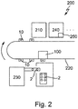
- FIG. 2 schematically illustrates a laboratory automation system 200 comprising the apparatus 100 depicted in Fig. 1 , an exemplary laboratory station 210, a centrifuge station 230, an aliquoter unit 240 including a pipetting station 250.
- the apparatus 100 and the pipetting station 250 are functionally coupled by means of a conventional data or field bus.
- the system may include further laboratory stations, such as pre analytical stations, analytical stations and post analytical stations.
- the pipetting station 250 transfers part of the sample 1 to one or more secondary tubes (not shown).
- the pipetting station 250 is adapted to pipette the sample 1, if the process control unit 5 initiates the pipetting of the sample 1 in the event that the deviation between the two liquid levels is smaller than the given threshold.
- the pipetting station 250 is adapted to discard the complete sample, i.e. to omit a pipetting step, if the process control unit 5 controls the discarding of the serum 1 in the event that the deviation between the two liquid levels is larger than or equal to the given threshold.
- the system 200 further includes a sample container transport unit adapted to transport sample containers 2 between the apparatus 100, the pipetting station 250 and further laboratory stations, e.g. the laboratory station 210.
- the sample container transport unit includes a number of sample container carriers 10 and a conveyor 220, wherein the sample container carriers 10 are attached to the conveyor 220.
- the optical sensing unit 3 and the tip sensing unit 4 may alternatively be provided at different locations of the laboratory automation system 200.
- the optical sensing unit 3 may e.g. be provided at a so called in-sort Station where the laboratory sample containers 2 comprising the corresponding samples are inserted into the system 200.
- the first liquid level may be determined when inserting the sample container into the system 200.
- the tip sensing unit 4 may be functionally coupled to the aliquoter unit 240 such that the second liquid level may be determined before and/or during pipetting the laboratory sample 1.
Landscapes
- Physics & Mathematics (AREA)
- General Physics & Mathematics (AREA)
- Fluid Mechanics (AREA)
- Electromagnetism (AREA)
- Thermal Sciences (AREA)
- Power Engineering (AREA)
- Engineering & Computer Science (AREA)
- Analytical Chemistry (AREA)
- Immunology (AREA)
- Pathology (AREA)
- General Health & Medical Sciences (AREA)
- Biochemistry (AREA)
- Chemical & Material Sciences (AREA)
- Life Sciences & Earth Sciences (AREA)
- Health & Medical Sciences (AREA)
- Automatic Analysis And Handling Materials Therefor (AREA)
- Investigating Or Analysing Materials By Optical Means (AREA)
Claims (11)
- Appareil (100) destiné à traiter un échantillon de laboratoire (1) contenu dans un récipient à échantillon de laboratoire (2), l'appareil (100) comprenant :- une unité de détection optique (3) pour détecter un facteur de transmission à différentes positions verticales à travers le récipient à échantillon de laboratoire (2),- une unité de détection de pointe (4) ayant une pointe (11), l'unité de détection de pointe (4) étant adaptée pour fournir un signal de détection de pointe (tLDS) dépendant d'une position de la pointe (11) par rapport à l'échantillon (1), et- une unité de contrôle de procédé (5), qui est adaptée pour contrôler le traitement de l'échantillon de laboratoire (1) en réponse au facteur de transmission et au signal de détection de pointe (tLDS).
- Appareil (100) selon la revendication 1, caractérisé en ce que- l'unité de contrôle de procédé (5) est adaptée pour déterminer un premier niveau de l'échantillon de laboratoire (1) dans le récipient à échantillon de laboratoire (2) en réponse au facteur de transmission,- l'unité de contrôle de procédé (5) est adaptée pour déterminer un deuxième niveau de l'échantillon de laboratoire (1) en réponse au signal de détection de pointe (tLDS),- l'unité de contrôle de procédé (5) est adaptée pour induire un pipetage de l'échantillon de laboratoire (1) si le premier niveau et le deuxième niveau diffèrent de moins d'un seuil donné, et- l'unité de contrôle de procédé (5) est adaptée pour induire une mise à l'écart et/ou une signalisation de l'échantillon de laboratoire (1) si le premier niveau et le deuxième niveau diffèrent de plus du seuil donné.
- Appareil (100) selon la revendication 1 ou 2, caractérisé en ce que- l'unité de détection optique (3) comprend :- une première source de lumière (3a) émettant de la lumière ayant une première longueur d'onde, la lumière ayant la première longueur d'onde étant transmise à travers le récipient à échantillon de laboratoire (2),- un premier détecteur de lumière (3b) qui est adapté pour détecter de la lumière ayant la première longueur d'onde transmise à travers le récipient à échantillon de laboratoire (2) et est adapté pour générer un premier signal de détecteur de lumière (LDS1) qui est représentatif du facteur de transmission à travers le récipient à échantillon de laboratoire (2) à la première longueur d'onde,- une deuxième source de lumière (3c) émettant de la lumière ayant une deuxième longueur d'onde, la lumière ayant la deuxième longueur d'onde étant transmise à travers le récipient à échantillon de laboratoire (2), et- un deuxième détecteur de lumière (3d) qui est adapté pour détecter de la lumière ayant la deuxième longueur d'onde transmise à travers le récipient à échantillon de laboratoire (2) et est adapté pour générer un deuxième signal de détecteur de lumière (LDS2) qui est représentatif du facteur de transmission à travers le récipient à échantillon de laboratoire (2) à la deuxième longueur d'onde,- dans lequel l'unité de contrôle de procédé (5) reçoit le premier signal de détecteur de lumière (LDS1) et le deuxième signal de détecteur de lumière (LDS2), et est adaptée pour contrôler le traitement de l'échantillon de laboratoire (1) en réponse au premier signal de détecteur de lumière (LDS1) et au deuxième signal de détecteur de lumière (LDS2), et au signal de détection de pointe (tLDS).
- Appareil (100) selon la revendication 3, caractérisé en ce que- la première source de lumière (3a) émet de la lumière ayant une longueur d'onde dans la gamme entre 150 nm à 1380 nm, et- la deuxième source de lumière (3c) émet de la lumière ayant une longueur d'onde dans la gamme entre 1400 nm et 4000 nm.
- Appareil (100) selon l'une quelconque des revendications précédentes, comprenant :- une unité d'entraînement (8) qui est adaptée pour déplacer le récipient à échantillon de laboratoire (2) par rapport à l'unité de détection optique (3) et la pointe (11),- dans lequel l'unité de contrôle de procédé (5) est adaptée pour contrôler le traitement de l'échantillon de laboratoire (1) en réponse au facteur de transmission et au signal de détection de pointe (tLDS) pour différentes positions relatives entre le récipient à échantillon de laboratoire (2) et l'unité de détection optique (3) et pour différentes positions relatives entre le récipient à échantillon de laboratoire (2) et la pointe (11).
- Appareil (100) selon la revendication 5, caractérisé en ce que- l'unité d'entraînement (8) est adaptée pour faire tourner le récipient à échantillon de laboratoire (2),- dans lequel l'unité de contrôle de procédé (5) est adaptée pour contrôler le traitement de l'échantillon de laboratoire (1) en réponse au facteur de transmission et au signal de détection de pointe (tLDS) pour le récipient à échantillon de laboratoire (2) en rotation.
- Appareil (100) selon l'une quelconque des revendications précédentes, comprenant :- une barrière lumineuse (9) qui est adaptée pour détecter l'introduction du récipient à échantillon de laboratoire (2) dans l'appareil,- l'appareil étant adapté pour activer l'unité de détection optique (3) et/ou l'unité de détection de pointe (4) et/ou l'unité de contrôle de procédé (5) quand l'introduction est détectée.
- Système d'automatisation de laboratoire (200), le système comprenant :- l'appareil (100) selon l'une quelconque des revendications précédentes, et- un nombre de postes de laboratoire (210) fonctionnellement couplés à l'appareil (100).
- Système d'automatisation de laboratoire (200) selon la revendication 8, caractérisé en ce que- le système d'automatisation de laboratoire (200) comprend un poste de pipetage de laboratoire (250), le poste de pipetage de laboratoire (250) étant contrôlé par l'unité de contrôle de procédé (5).
- Système d'automatisation de laboratoire (200) selon la revendication 8 ou 9, caractérisé en ce que- au moins un du nombre de postes de laboratoire (210) est adapté pour analyser l'échantillon de laboratoire (1).
- Procédé de pipetage d'un échantillon de laboratoire (1) contenu dans un récipient à échantillon de laboratoire (2), le procédé comprenant :- la détection d'un facteur de transmission à différentes positions verticales à travers le récipient à échantillon de laboratoire (2),- la fourniture d'un signal de détection de pointe (tLDS) par une unité de détection de pointe ayant une pointe, le signal de détection de pointe (tLDS) dépendant d'une position de la pointe (11) par rapport à l'échantillon (1), et- le pipetage de l'échantillon de laboratoire (1) en réponse au facteur de transmission et au signal de détection de pointe (tLDS).
Applications Claiming Priority (2)
| Application Number | Priority Date | Filing Date | Title |
|---|---|---|---|
| EP16178576 | 2016-07-08 | ||
| PCT/EP2017/067151 WO2018007621A1 (fr) | 2016-07-08 | 2017-07-07 | Appareil de traitement d'un échantillon de laboratoire, système d'automatisation de laboratoire et procédé de pipettage d'un échantillon de laboratoire |
Publications (2)
| Publication Number | Publication Date |
|---|---|
| EP3482170A1 EP3482170A1 (fr) | 2019-05-15 |
| EP3482170B1 true EP3482170B1 (fr) | 2020-02-12 |
Family
ID=56557473
Family Applications (1)
| Application Number | Title | Priority Date | Filing Date |
|---|---|---|---|
| EP17735566.6A Active EP3482170B1 (fr) | 2016-07-08 | 2017-07-07 | Système d'automatisation de laboratoire et procédé permettant de pipetter un échantillon de laboratoire |
Country Status (5)
| Country | Link |
|---|---|
| US (1) | US11125601B2 (fr) |
| EP (1) | EP3482170B1 (fr) |
| JP (1) | JP6768917B2 (fr) |
| CN (1) | CN109791067B (fr) |
| WO (1) | WO2018007621A1 (fr) |
Families Citing this family (6)
| Publication number | Priority date | Publication date | Assignee | Title |
|---|---|---|---|---|
| SG11201703597TA (en) | 2014-11-14 | 2017-06-29 | Hoffmann La Roche | Antigen binding molecules comprising a tnf family ligand trimer |
| AR106188A1 (es) | 2015-10-01 | 2017-12-20 | Hoffmann La Roche | Anticuerpos anti-cd19 humano humanizados y métodos de utilización |
| EP3550308A1 (fr) * | 2018-04-05 | 2019-10-09 | Siemens Healthcare Diagnostics Products GmbH | Système d'analyse de laboratoire à pipetage d'échantillon amélioré |
| JP7129456B2 (ja) * | 2019-11-15 | 2022-09-01 | エフ ホフマン-ラ ロッシュ アクチェン ゲゼルシャフト | 検査室サンプル容器の特性を判定するための装置、検査室自動化システム、および検査室サンプル容器の特性を判定するための方法 |
| EP3840014A1 (fr) * | 2019-12-17 | 2021-06-23 | F. Hoffmann-La Roche AG | Procédé automatisé de maintien d'un système de diagnostic clinique |
| EP4092394A1 (fr) * | 2021-05-19 | 2022-11-23 | Roche Diagnostics GmbH | Appareil pour déterminer une position verticale d'au moins une interface entre un premier composant et au moins un deuxiéme composant |
Citations (1)
| Publication number | Priority date | Publication date | Assignee | Title |
|---|---|---|---|---|
| US4873875A (en) * | 1986-06-27 | 1989-10-17 | Prism Technology, Inc. | System for optically interrogating liquid samples and for withdrawing selected sample portions |
Family Cites Families (25)
| Publication number | Priority date | Publication date | Assignee | Title |
|---|---|---|---|---|
| US5648727A (en) | 1995-10-24 | 1997-07-15 | Dpc Cirrus Inc. | Capacitive level sensing pipette probe |
| JP2000193670A (ja) * | 1998-12-28 | 2000-07-14 | Yuichi Chikakiyo | 検体分注システム |
| US7473897B2 (en) * | 2001-09-12 | 2009-01-06 | Tecan Trading Ag | System, method, and computer program for conducting optical transmission measurements and evaluating determined measuring variables |
| JP2007322285A (ja) * | 2006-06-01 | 2007-12-13 | Olympus Corp | 分注装置 |
| JP2009174869A (ja) * | 2008-01-21 | 2009-08-06 | Olympus Corp | 分注装置、自動分析装置、分注装置の制御プログラム、および分注方法 |
| CN100575890C (zh) * | 2008-09-10 | 2009-12-30 | 南京林业大学 | 电容式液位传感器及应用该传感器的液位检测装置 |
| JP2010197047A (ja) * | 2009-02-20 | 2010-09-09 | Beckman Coulter Inc | 分注方法、分析装置および分析装置 |
| JP5093164B2 (ja) * | 2009-03-16 | 2012-12-05 | 株式会社島津製作所 | サンプリング機構 |
| US7982201B2 (en) * | 2009-09-08 | 2011-07-19 | Jadak, Llc | System and method for detection of liquid level in a vessel |
| WO2011067171A1 (fr) * | 2009-12-01 | 2011-06-09 | Nestec S.A. | Ensemble débitmètre pour une machine à boisson |
| DE102010013410A1 (de) * | 2010-03-30 | 2010-08-05 | Reimer Offen | Flüssigkeitsdetektor |
| CN102095473B (zh) * | 2010-12-26 | 2012-06-13 | 河海大学常州校区 | 透射式光电液位计 |
| WO2013036941A2 (fr) | 2011-09-09 | 2013-03-14 | Gen-Probe Incorporated | Instrumentation de maniement automatisé d'échantillons, systèmes, processus et procédés associés |
| JP5761753B2 (ja) * | 2011-09-20 | 2015-08-12 | 株式会社日立ハイテクノロジーズ | 自動分析装置及びその動作不良判定方法 |
| WO2013060480A2 (fr) * | 2011-10-28 | 2013-05-02 | Torsten Matthias | Dispositif et procédé de contrôle du volume d'un prélèvement |
| JP5930865B2 (ja) | 2012-06-22 | 2016-06-08 | 株式会社日立ハイテクノロジーズ | 検出装置および生体試料分析装置 |
| US20140036276A1 (en) * | 2012-08-06 | 2014-02-06 | Beckman Coulter, Inc. | Sensing specimen gripper |
| EP2770318B1 (fr) | 2013-02-21 | 2018-03-21 | Roche Diagniostics GmbH | Procédé et appareil de détection de caillots dans un liquide et système d'automatisation de laboratoire |
| EP2770317B1 (fr) * | 2013-02-21 | 2017-09-20 | Roche Diagnostics GmbH | Appareil permettant de déterminer une position verticale d'au moins une interface entre un premier composant et au moins un deuxième composant et système d'automatisation de laboratoire |
| WO2015056649A1 (fr) | 2013-10-17 | 2015-04-23 | 株式会社日立ハイテクノロジーズ | Système d'automatisation d'inspection d'échantillon, module de vérification de capacité, et procédé de vérification d'échantillon biologique |
| JP6274081B2 (ja) * | 2013-12-16 | 2018-02-07 | 株式会社島津製作所 | 液採取装置及びその液採取装置を備えた自動分析装置 |
| US10429401B2 (en) * | 2014-07-21 | 2019-10-01 | Beckman Coulter, Inc. | Methods and systems for tube inspection and liquid level detection |
| CH709917A2 (de) * | 2014-07-24 | 2016-01-29 | Tecan Trading Ag | Verfahren und Vorrichtung zum Unterscheiden zwischen einer Schaum- und/oder Flüssigkeitskontaktierung. |
| CN104121965A (zh) * | 2014-08-08 | 2014-10-29 | 南京航空航天大学 | 一种油水检测装置及其检测方法 |
| CN204963951U (zh) * | 2015-09-07 | 2016-01-13 | 长春光机医疗仪器有限公司 | 一种液位探测系统 |
-
2017
- 2017-07-07 CN CN201780042570.9A patent/CN109791067B/zh active Active
- 2017-07-07 JP JP2019500449A patent/JP6768917B2/ja active Active
- 2017-07-07 WO PCT/EP2017/067151 patent/WO2018007621A1/fr active Search and Examination
- 2017-07-07 EP EP17735566.6A patent/EP3482170B1/fr active Active
-
2018
- 2018-12-20 US US16/226,889 patent/US11125601B2/en active Active
Patent Citations (1)
| Publication number | Priority date | Publication date | Assignee | Title |
|---|---|---|---|---|
| US4873875A (en) * | 1986-06-27 | 1989-10-17 | Prism Technology, Inc. | System for optically interrogating liquid samples and for withdrawing selected sample portions |
Also Published As
| Publication number | Publication date |
|---|---|
| US11125601B2 (en) | 2021-09-21 |
| CN109791067B (zh) | 2021-09-07 |
| JP6768917B2 (ja) | 2020-10-14 |
| US20190120682A1 (en) | 2019-04-25 |
| JP2019520584A (ja) | 2019-07-18 |
| CN109791067A (zh) | 2019-05-21 |
| WO2018007621A1 (fr) | 2018-01-11 |
| EP3482170A1 (fr) | 2019-05-15 |
Similar Documents
| Publication | Publication Date | Title |
|---|---|---|
| EP3482170B1 (fr) | Système d'automatisation de laboratoire et procédé permettant de pipetter un échantillon de laboratoire | |
| EP2770318B1 (fr) | Procédé et appareil de détection de caillots dans un liquide et système d'automatisation de laboratoire | |
| KR100649789B1 (ko) | 혈액 검체 검출장치 | |
| EP2770317B1 (fr) | Appareil permettant de déterminer une position verticale d'au moins une interface entre un premier composant et au moins un deuxième composant et système d'automatisation de laboratoire | |
| US20160018427A1 (en) | Methods and systems for tube inspection and liquid level detection | |
| US11422143B2 (en) | Sample measuring apparatus and sample measuring method | |
| JP2014006094A (ja) | 検出装置および生体試料分析装置 | |
| CN101470124A (zh) | 自动分析装置及其分注方法 | |
| US20210213450A1 (en) | Method and laboratory system to process a laboratory carrier based on a feature of a test liquid in the laboratory carrier | |
| JP5993652B2 (ja) | 自動分析装置 | |
| JP6733988B2 (ja) | 自動分析装置 | |
| JP6929467B2 (ja) | 液面検知装置 | |
| JP4423171B2 (ja) | 検体処理装置 | |
| EP4137784A1 (fr) | Système de laboratoire et procédé de détermination d'une information | |
| JP2023523593A (ja) | サンプル容器における流体レベルの差分測定のためのシステムおよび方法 | |
| JP2010185829A (ja) | 分注機構、分注方法及び分析装置 |
Legal Events
| Date | Code | Title | Description |
|---|---|---|---|
| STAA | Information on the status of an ep patent application or granted ep patent |
Free format text: STATUS: UNKNOWN |
|
| STAA | Information on the status of an ep patent application or granted ep patent |
Free format text: STATUS: THE INTERNATIONAL PUBLICATION HAS BEEN MADE |
|
| PUAI | Public reference made under article 153(3) epc to a published international application that has entered the european phase |
Free format text: ORIGINAL CODE: 0009012 |
|
| STAA | Information on the status of an ep patent application or granted ep patent |
Free format text: STATUS: REQUEST FOR EXAMINATION WAS MADE |
|
| 17P | Request for examination filed |
Effective date: 20190201 |
|
| AK | Designated contracting states |
Kind code of ref document: A1 Designated state(s): AL AT BE BG CH CY CZ DE DK EE ES FI FR GB GR HR HU IE IS IT LI LT LU LV MC MK MT NL NO PL PT RO RS SE SI SK SM TR |
|
| AX | Request for extension of the european patent |
Extension state: BA ME |
|
| GRAP | Despatch of communication of intention to grant a patent |
Free format text: ORIGINAL CODE: EPIDOSNIGR1 |
|
| STAA | Information on the status of an ep patent application or granted ep patent |
Free format text: STATUS: GRANT OF PATENT IS INTENDED |
|
| INTG | Intention to grant announced |
Effective date: 20190816 |
|
| DAV | Request for validation of the european patent (deleted) | ||
| DAX | Request for extension of the european patent (deleted) | ||
| GRAS | Grant fee paid |
Free format text: ORIGINAL CODE: EPIDOSNIGR3 |
|
| GRAA | (expected) grant |
Free format text: ORIGINAL CODE: 0009210 |
|
| STAA | Information on the status of an ep patent application or granted ep patent |
Free format text: STATUS: THE PATENT HAS BEEN GRANTED |
|
| AK | Designated contracting states |
Kind code of ref document: B1 Designated state(s): AL AT BE BG CH CY CZ DE DK EE ES FI FR GB GR HR HU IE IS IT LI LT LU LV MC MK MT NL NO PL PT RO RS SE SI SK SM TR |
|
| REG | Reference to a national code |
Ref country code: GB Ref legal event code: FG4D |
|
| REG | Reference to a national code |
Ref country code: CH Ref legal event code: EP |
|
| REG | Reference to a national code |
Ref country code: AT Ref legal event code: REF Ref document number: 1232733 Country of ref document: AT Kind code of ref document: T Effective date: 20200215 |
|
| REG | Reference to a national code |
Ref country code: IE Ref legal event code: FG4D |
|
| REG | Reference to a national code |
Ref country code: DE Ref legal event code: R096 Ref document number: 602017011733 Country of ref document: DE |
|
| PG25 | Lapsed in a contracting state [announced via postgrant information from national office to epo] |
Ref country code: RS Free format text: LAPSE BECAUSE OF FAILURE TO SUBMIT A TRANSLATION OF THE DESCRIPTION OR TO PAY THE FEE WITHIN THE PRESCRIBED TIME-LIMIT Effective date: 20200212 Ref country code: FI Free format text: LAPSE BECAUSE OF FAILURE TO SUBMIT A TRANSLATION OF THE DESCRIPTION OR TO PAY THE FEE WITHIN THE PRESCRIBED TIME-LIMIT Effective date: 20200212 Ref country code: NO Free format text: LAPSE BECAUSE OF FAILURE TO SUBMIT A TRANSLATION OF THE DESCRIPTION OR TO PAY THE FEE WITHIN THE PRESCRIBED TIME-LIMIT Effective date: 20200512 |
|
| REG | Reference to a national code |
Ref country code: LT Ref legal event code: MG4D |
|
| REG | Reference to a national code |
Ref country code: NL Ref legal event code: MP Effective date: 20200212 |
|
| PG25 | Lapsed in a contracting state [announced via postgrant information from national office to epo] |
Ref country code: GR Free format text: LAPSE BECAUSE OF FAILURE TO SUBMIT A TRANSLATION OF THE DESCRIPTION OR TO PAY THE FEE WITHIN THE PRESCRIBED TIME-LIMIT Effective date: 20200513 Ref country code: BG Free format text: LAPSE BECAUSE OF FAILURE TO SUBMIT A TRANSLATION OF THE DESCRIPTION OR TO PAY THE FEE WITHIN THE PRESCRIBED TIME-LIMIT Effective date: 20200512 Ref country code: HR Free format text: LAPSE BECAUSE OF FAILURE TO SUBMIT A TRANSLATION OF THE DESCRIPTION OR TO PAY THE FEE WITHIN THE PRESCRIBED TIME-LIMIT Effective date: 20200212 Ref country code: IS Free format text: LAPSE BECAUSE OF FAILURE TO SUBMIT A TRANSLATION OF THE DESCRIPTION OR TO PAY THE FEE WITHIN THE PRESCRIBED TIME-LIMIT Effective date: 20200612 Ref country code: SE Free format text: LAPSE BECAUSE OF FAILURE TO SUBMIT A TRANSLATION OF THE DESCRIPTION OR TO PAY THE FEE WITHIN THE PRESCRIBED TIME-LIMIT Effective date: 20200212 Ref country code: LV Free format text: LAPSE BECAUSE OF FAILURE TO SUBMIT A TRANSLATION OF THE DESCRIPTION OR TO PAY THE FEE WITHIN THE PRESCRIBED TIME-LIMIT Effective date: 20200212 |
|
| PG25 | Lapsed in a contracting state [announced via postgrant information from national office to epo] |
Ref country code: NL Free format text: LAPSE BECAUSE OF FAILURE TO SUBMIT A TRANSLATION OF THE DESCRIPTION OR TO PAY THE FEE WITHIN THE PRESCRIBED TIME-LIMIT Effective date: 20200212 |
|
| PG25 | Lapsed in a contracting state [announced via postgrant information from national office to epo] |
Ref country code: EE Free format text: LAPSE BECAUSE OF FAILURE TO SUBMIT A TRANSLATION OF THE DESCRIPTION OR TO PAY THE FEE WITHIN THE PRESCRIBED TIME-LIMIT Effective date: 20200212 Ref country code: SM Free format text: LAPSE BECAUSE OF FAILURE TO SUBMIT A TRANSLATION OF THE DESCRIPTION OR TO PAY THE FEE WITHIN THE PRESCRIBED TIME-LIMIT Effective date: 20200212 Ref country code: SK Free format text: LAPSE BECAUSE OF FAILURE TO SUBMIT A TRANSLATION OF THE DESCRIPTION OR TO PAY THE FEE WITHIN THE PRESCRIBED TIME-LIMIT Effective date: 20200212 Ref country code: DK Free format text: LAPSE BECAUSE OF FAILURE TO SUBMIT A TRANSLATION OF THE DESCRIPTION OR TO PAY THE FEE WITHIN THE PRESCRIBED TIME-LIMIT Effective date: 20200212 Ref country code: CZ Free format text: LAPSE BECAUSE OF FAILURE TO SUBMIT A TRANSLATION OF THE DESCRIPTION OR TO PAY THE FEE WITHIN THE PRESCRIBED TIME-LIMIT Effective date: 20200212 Ref country code: RO Free format text: LAPSE BECAUSE OF FAILURE TO SUBMIT A TRANSLATION OF THE DESCRIPTION OR TO PAY THE FEE WITHIN THE PRESCRIBED TIME-LIMIT Effective date: 20200212 Ref country code: LT Free format text: LAPSE BECAUSE OF FAILURE TO SUBMIT A TRANSLATION OF THE DESCRIPTION OR TO PAY THE FEE WITHIN THE PRESCRIBED TIME-LIMIT Effective date: 20200212 Ref country code: ES Free format text: LAPSE BECAUSE OF FAILURE TO SUBMIT A TRANSLATION OF THE DESCRIPTION OR TO PAY THE FEE WITHIN THE PRESCRIBED TIME-LIMIT Effective date: 20200212 Ref country code: PT Free format text: LAPSE BECAUSE OF FAILURE TO SUBMIT A TRANSLATION OF THE DESCRIPTION OR TO PAY THE FEE WITHIN THE PRESCRIBED TIME-LIMIT Effective date: 20200705 |
|
| REG | Reference to a national code |
Ref country code: DE Ref legal event code: R097 Ref document number: 602017011733 Country of ref document: DE |
|
| REG | Reference to a national code |
Ref country code: AT Ref legal event code: MK05 Ref document number: 1232733 Country of ref document: AT Kind code of ref document: T Effective date: 20200212 |
|
| PLBE | No opposition filed within time limit |
Free format text: ORIGINAL CODE: 0009261 |
|
| STAA | Information on the status of an ep patent application or granted ep patent |
Free format text: STATUS: NO OPPOSITION FILED WITHIN TIME LIMIT |
|
| 26N | No opposition filed |
Effective date: 20201113 |
|
| PG25 | Lapsed in a contracting state [announced via postgrant information from national office to epo] |
Ref country code: AT Free format text: LAPSE BECAUSE OF FAILURE TO SUBMIT A TRANSLATION OF THE DESCRIPTION OR TO PAY THE FEE WITHIN THE PRESCRIBED TIME-LIMIT Effective date: 20200212 |
|
| PG25 | Lapsed in a contracting state [announced via postgrant information from national office to epo] |
Ref country code: SI Free format text: LAPSE BECAUSE OF FAILURE TO SUBMIT A TRANSLATION OF THE DESCRIPTION OR TO PAY THE FEE WITHIN THE PRESCRIBED TIME-LIMIT Effective date: 20200212 Ref country code: MC Free format text: LAPSE BECAUSE OF FAILURE TO SUBMIT A TRANSLATION OF THE DESCRIPTION OR TO PAY THE FEE WITHIN THE PRESCRIBED TIME-LIMIT Effective date: 20200212 Ref country code: PL Free format text: LAPSE BECAUSE OF FAILURE TO SUBMIT A TRANSLATION OF THE DESCRIPTION OR TO PAY THE FEE WITHIN THE PRESCRIBED TIME-LIMIT Effective date: 20200212 |
|
| REG | Reference to a national code |
Ref country code: BE Ref legal event code: MM Effective date: 20200731 |
|
| PG25 | Lapsed in a contracting state [announced via postgrant information from national office to epo] |
Ref country code: LU Free format text: LAPSE BECAUSE OF NON-PAYMENT OF DUE FEES Effective date: 20200707 Ref country code: IE Free format text: LAPSE BECAUSE OF NON-PAYMENT OF DUE FEES Effective date: 20200707 |
|
| PG25 | Lapsed in a contracting state [announced via postgrant information from national office to epo] |
Ref country code: BE Free format text: LAPSE BECAUSE OF NON-PAYMENT OF DUE FEES Effective date: 20200731 |
|
| PG25 | Lapsed in a contracting state [announced via postgrant information from national office to epo] |
Ref country code: TR Free format text: LAPSE BECAUSE OF FAILURE TO SUBMIT A TRANSLATION OF THE DESCRIPTION OR TO PAY THE FEE WITHIN THE PRESCRIBED TIME-LIMIT Effective date: 20200212 Ref country code: MT Free format text: LAPSE BECAUSE OF FAILURE TO SUBMIT A TRANSLATION OF THE DESCRIPTION OR TO PAY THE FEE WITHIN THE PRESCRIBED TIME-LIMIT Effective date: 20200212 Ref country code: CY Free format text: LAPSE BECAUSE OF FAILURE TO SUBMIT A TRANSLATION OF THE DESCRIPTION OR TO PAY THE FEE WITHIN THE PRESCRIBED TIME-LIMIT Effective date: 20200212 |
|
| PG25 | Lapsed in a contracting state [announced via postgrant information from national office to epo] |
Ref country code: MK Free format text: LAPSE BECAUSE OF FAILURE TO SUBMIT A TRANSLATION OF THE DESCRIPTION OR TO PAY THE FEE WITHIN THE PRESCRIBED TIME-LIMIT Effective date: 20200212 Ref country code: AL Free format text: LAPSE BECAUSE OF FAILURE TO SUBMIT A TRANSLATION OF THE DESCRIPTION OR TO PAY THE FEE WITHIN THE PRESCRIBED TIME-LIMIT Effective date: 20200212 |
|
| PGFP | Annual fee paid to national office [announced via postgrant information from national office to epo] |
Ref country code: IT Payment date: 20230620 Year of fee payment: 7 |
|
| PGFP | Annual fee paid to national office [announced via postgrant information from national office to epo] |
Ref country code: GB Payment date: 20230620 Year of fee payment: 7 Ref country code: CH Payment date: 20230801 Year of fee payment: 7 |
|
| PGFP | Annual fee paid to national office [announced via postgrant information from national office to epo] |
Ref country code: FR Payment date: 20230724 Year of fee payment: 7 Ref country code: DE Payment date: 20230620 Year of fee payment: 7 |