EP3481715B1 - Tanksystem für ein unterseeboot mit brennstoffzelle - Google Patents
Tanksystem für ein unterseeboot mit brennstoffzelle Download PDFInfo
- Publication number
- EP3481715B1 EP3481715B1 EP17734740.8A EP17734740A EP3481715B1 EP 3481715 B1 EP3481715 B1 EP 3481715B1 EP 17734740 A EP17734740 A EP 17734740A EP 3481715 B1 EP3481715 B1 EP 3481715B1
- Authority
- EP
- European Patent Office
- Prior art keywords
- tank
- methanol
- submarine
- water
- valve
- Prior art date
- Legal status (The legal status is an assumption and is not a legal conclusion. Google has not performed a legal analysis and makes no representation as to the accuracy of the status listed.)
- Active
Links
Images
Classifications
-
- B—PERFORMING OPERATIONS; TRANSPORTING
- B63—SHIPS OR OTHER WATERBORNE VESSELS; RELATED EQUIPMENT
- B63G—OFFENSIVE OR DEFENSIVE ARRANGEMENTS ON VESSELS; MINE-LAYING; MINE-SWEEPING; SUBMARINES; AIRCRAFT CARRIERS
- B63G8/00—Underwater vessels, e.g. submarines; Equipment specially adapted therefor
- B63G8/08—Propulsion
-
- B—PERFORMING OPERATIONS; TRANSPORTING
- B63—SHIPS OR OTHER WATERBORNE VESSELS; RELATED EQUIPMENT
- B63G—OFFENSIVE OR DEFENSIVE ARRANGEMENTS ON VESSELS; MINE-LAYING; MINE-SWEEPING; SUBMARINES; AIRCRAFT CARRIERS
- B63G8/00—Underwater vessels, e.g. submarines; Equipment specially adapted therefor
- B63G8/14—Control of attitude or depth
- B63G8/22—Adjustment of buoyancy by water ballasting; Emptying equipment for ballast tanks
-
- H—ELECTRICITY
- H01—ELECTRIC ELEMENTS
- H01M—PROCESSES OR MEANS, e.g. BATTERIES, FOR THE DIRECT CONVERSION OF CHEMICAL ENERGY INTO ELECTRICAL ENERGY
- H01M8/00—Fuel cells; Manufacture thereof
- H01M8/04—Auxiliary arrangements, e.g. for control of pressure or for circulation of fluids
- H01M8/04082—Arrangements for control of reactant parameters, e.g. pressure or concentration
- H01M8/04089—Arrangements for control of reactant parameters, e.g. pressure or concentration of gaseous reactants
- H01M8/04119—Arrangements for control of reactant parameters, e.g. pressure or concentration of gaseous reactants with simultaneous supply or evacuation of electrolyte; Humidifying or dehumidifying
- H01M8/04156—Arrangements for control of reactant parameters, e.g. pressure or concentration of gaseous reactants with simultaneous supply or evacuation of electrolyte; Humidifying or dehumidifying with product water removal
-
- H—ELECTRICITY
- H01—ELECTRIC ELEMENTS
- H01M—PROCESSES OR MEANS, e.g. BATTERIES, FOR THE DIRECT CONVERSION OF CHEMICAL ENERGY INTO ELECTRICAL ENERGY
- H01M8/00—Fuel cells; Manufacture thereof
- H01M8/04—Auxiliary arrangements, e.g. for control of pressure or for circulation of fluids
- H01M8/04082—Arrangements for control of reactant parameters, e.g. pressure or concentration
- H01M8/04201—Reactant storage and supply, e.g. means for feeding, pipes
-
- H—ELECTRICITY
- H01—ELECTRIC ELEMENTS
- H01M—PROCESSES OR MEANS, e.g. BATTERIES, FOR THE DIRECT CONVERSION OF CHEMICAL ENERGY INTO ELECTRICAL ENERGY
- H01M8/00—Fuel cells; Manufacture thereof
- H01M8/04—Auxiliary arrangements, e.g. for control of pressure or for circulation of fluids
- H01M8/04291—Arrangements for managing water in solid electrolyte fuel cell systems
-
- H—ELECTRICITY
- H01—ELECTRIC ELEMENTS
- H01M—PROCESSES OR MEANS, e.g. BATTERIES, FOR THE DIRECT CONVERSION OF CHEMICAL ENERGY INTO ELECTRICAL ENERGY
- H01M8/00—Fuel cells; Manufacture thereof
- H01M8/06—Combination of fuel cells with means for production of reactants or for treatment of residues
- H01M8/0606—Combination of fuel cells with means for production of reactants or for treatment of residues with means for production of gaseous reactants
- H01M8/0612—Combination of fuel cells with means for production of reactants or for treatment of residues with means for production of gaseous reactants from carbon-containing material
- H01M8/0618—Reforming processes, e.g. autothermal, partial oxidation or steam reforming
-
- B—PERFORMING OPERATIONS; TRANSPORTING
- B63—SHIPS OR OTHER WATERBORNE VESSELS; RELATED EQUIPMENT
- B63H—MARINE PROPULSION OR STEERING
- B63H21/00—Use of propulsion power plant or units on vessels
- B63H2021/003—Use of propulsion power plant or units on vessels the power plant using fuel cells for energy supply or accumulation, e.g. for buffering photovoltaic energy
-
- H—ELECTRICITY
- H01—ELECTRIC ELEMENTS
- H01M—PROCESSES OR MEANS, e.g. BATTERIES, FOR THE DIRECT CONVERSION OF CHEMICAL ENERGY INTO ELECTRICAL ENERGY
- H01M2250/00—Fuel cells for particular applications; Specific features of fuel cell system
- H01M2250/20—Fuel cells in motive systems, e.g. vehicle, ship, plane
-
- Y—GENERAL TAGGING OF NEW TECHNOLOGICAL DEVELOPMENTS; GENERAL TAGGING OF CROSS-SECTIONAL TECHNOLOGIES SPANNING OVER SEVERAL SECTIONS OF THE IPC; TECHNICAL SUBJECTS COVERED BY FORMER USPC CROSS-REFERENCE ART COLLECTIONS [XRACs] AND DIGESTS
- Y02—TECHNOLOGIES OR APPLICATIONS FOR MITIGATION OR ADAPTATION AGAINST CLIMATE CHANGE
- Y02E—REDUCTION OF GREENHOUSE GAS [GHG] EMISSIONS, RELATED TO ENERGY GENERATION, TRANSMISSION OR DISTRIBUTION
- Y02E60/00—Enabling technologies; Technologies with a potential or indirect contribution to GHG emissions mitigation
- Y02E60/30—Hydrogen technology
- Y02E60/50—Fuel cells
-
- Y—GENERAL TAGGING OF NEW TECHNOLOGICAL DEVELOPMENTS; GENERAL TAGGING OF CROSS-SECTIONAL TECHNOLOGIES SPANNING OVER SEVERAL SECTIONS OF THE IPC; TECHNICAL SUBJECTS COVERED BY FORMER USPC CROSS-REFERENCE ART COLLECTIONS [XRACs] AND DIGESTS
- Y02—TECHNOLOGIES OR APPLICATIONS FOR MITIGATION OR ADAPTATION AGAINST CLIMATE CHANGE
- Y02T—CLIMATE CHANGE MITIGATION TECHNOLOGIES RELATED TO TRANSPORTATION
- Y02T90/00—Enabling technologies or technologies with a potential or indirect contribution to GHG emissions mitigation
- Y02T90/40—Application of hydrogen technology to transportation, e.g. using fuel cells
Definitions
- the invention relates to a submarine that generates energy using a fuel cell, with the hydrogen required for the fuel cell being obtained from methanol in a reformer.
- the submarine has at least three tanks in which methanol and water are stored alternately.
- the use of fuel cells is known in the field of non-nuclear submarines, for example the Class 212 A.
- the hydrogen required for the operation of the fuel cell is stored in metal hydride storage tanks.
- Metal hydride storage systems have proven to be very suitable for boats with a displacement of approximately 2,000 tons. However, for boats with significantly higher displacement, it may be more efficient to integrate a reformer into the boat in addition to or instead of the metal hydride storage systems and to carry methanol in a compact storage container.
- the object of the invention is to create a submarine which uses methanol as fuel and has the smallest possible change in buoyancy when consuming the methanol.
- the submarine according to the invention has at least one first fuel cell and at least one first reformer.
- the at least one first reformer is designed to produce hydrogen from methanol.
- the submarine has at least a first tank, a second tank, and a third tank.
- the first tank is connectable to the reformer for fluid transport
- the second tank is connectable to the reformer for fluid transport
- the third tank is connectable to the reformer for fluid transport.
- the first tank is connectable to the second tank for fluid transport
- the first tank is connectable to the third tank for fluid transport
- the second tank is connectable to the third tank for fluid transport.
- the reformer To produce hydrogen from methanol, the reformer must be supplied with both methanol and water. To do this efficiently, the submarine has at least three tanks, preferably more than three. These tanks can store methanol or water. Since there are no defined methanol storage tanks and water storage tanks, each tank must be connected to the reformer. Additionally, it is necessary to be able to pump fluids from one tank to another, so that each tank can be connected to any other tank.
- water refers in particular to process water required or generated in connection with the operation of the reformer or fuel cell. Drinking water carried on board is to be distinguished from this. Water within the meaning of the invention generally contains impurities, particularly methanol; it is not chemically pure water.
- one tank will contain water, while all other tanks will be filled with methanol.
- the tank containing water is only partially filled so that it can absorb the reaction water and condensate produced by the reformer and/or fuel cell.
- methanol is removed, and as soon as a tank containing methanol is empty, the reaction water and condensate produced by the reformer and/or fuel cell are introduced into it.
- the first tank is connected to a first outlet valve at the bottom and to a first inlet valve at the top.
- the second tank is connected to a second outlet valve at the bottom and to a second inlet valve at the top.
- the third tank is connected to a third outlet valve at the bottom and to a third inlet valve at the top.
- each tank is provided with a single inlet valve on top for the transport of methanol and/or water.
- the first outlet valve, the second outlet valve and the third outlet valve are connected via an outlet connection.
- the first inlet valve, the second inlet valve and the third inlet valve are connected via an inlet connection.
- the inlet and outlet connections are connected via a pump. This makes it particularly easy to transport liquid from each tank to every other tank using only a single active pump element.
- the inlet connection is connected to a refueling coupling.
- Methanol or water can be pumped into the inlet connection via the refueling coupling and into a selected tank via the inlet connection.
- the first tank is connected to a first methanol discharge valve at its bottom.
- the second tank is connected to a second methanol discharge valve at its bottom, and the third tank is connected to a third methanol discharge valve at its bottom.
- the first methanol discharge valve, the second methanol discharge valve and the third methanol discharge valve are connected via a methanol discharge connection.
- the methanol discharge connection is connected to the at least one first reformer via at least one first methanol discharge pump.
- This design allows methanol to be transported from any tank to the first reformer.
- the first tank is connected to a first water drain valve at its bottom.
- the second tank is connected to a second water drain valve at its bottom.
- the third tank is connected to a third water drain valve at its bottom.
- the first water drain valve, the second water drain valve and the third water drain valve are connected via a water drain connection.
- the water drain connection is connected to the at least one first reformer via at least one first water drain pump.
- This design allows water from each tank to be pumped into the first reformer.
- the outlet valve, the methanol drain valve and the water drain valve of a tank are each connected to the tank via a common connection, so that there is only one opening at the bottom for connection to the three valves.
- the first tank, the second tank, and the third tank are sealed from the atmosphere of the submarine, wherein the submarine has a device for introducing inert gas into at least the first tank, the second tank, and the third tank. Since methanol is toxic, methanol should not be released into the atmosphere in gaseous form. This can be achieved, in particular, by a protective gas atmosphere. At the same time, this also ensures explosion protection.
- the inert gas is nitrogen, carbon dioxide, helium, neon, argon, or a mixture thereof. Nitrogen, carbon dioxide, or argon is particularly preferred, since these gases can be used for various purposes on board a submarine.
- At least two tanks are arranged adjacent to each other.
- the two adjacent tanks are connected at the top by an overflow pipe, with the connections between the overflow pipe and the tanks being located on the side opposite the adjacent tank.
- the submarine has at least one degassing tank. After degassing, the water can be conveyed from the degassing tank via the inlet connection into a selected tank.
- the submarine has a cathode-side water separator, wherein the cathode-side water separator is connected to the cathode side of the at least one fuel cell, wherein the cathode-side water separator is connected to the outgassing tank.
- Reaction water from the cathode side of the fuel cell is first conveyed to the outgassing tank.
- the reaction water from the cathode side of the fuel cell is enriched with oxygen. This oxygen can be released into the atmosphere in the outgassing tank.
- Reaction water from the anode side of the fuel cell is produced in significantly smaller quantities, as the product is produced on the cathode side.
- this water may contain hydrogen, it is preferably stored in a separate tank or used to humidify the hydrogen stream in the feed to the anode side of the fuel cell.
- the outgassing tank is connected to the reformer for transferring condensate from the reformer to the outgassing tank.
- the outgassing tank is connected to the atmosphere of the submarine. Since oxygen is mainly released here, which is the crew, there are no further storage or disposal requirements.
- the submarine has an even number of tanks, with half of the tanks arranged on the starboard side and the other half on the port side.
- the submarine has a total of eight tanks, with four tanks arranged on the starboard side and four tanks on the port side.
- one of the tanks is a degassing tank.
- the submarine has a pressure hull, and the tanks are arranged outside the pressure hull. These tanks are preferably arranged between the pressure hull of the submarine and another fairing. Particularly preferably, they are arranged around another tank, in particular the oxygen tank.
- each tank has only one inlet for liquids on the top and one outlet for liquids on the bottom. Additionally, each tank preferably has at least one inlet for protective gas. Further preferably, each tank has at least one overflow pipe. Additionally, each tank can have a fill level sensor and, if appropriate, pressure and/or temperature sensors.
- the pressure body forms at least part of the tank.
- At least one tank has a bladder, wherein the bladder is designed to hold liquid.
- a bladder is understood to be a flexible device for holding liquid, which is usually made of a plastic. The bladder increases its volume when liquid is added and decreases its volume when liquid is removed. The bladder can prevent contact between the liquid and the tank wall.
- One advantage of using a bladder is that it does not require a protective gas atmosphere, since methanol vapors cannot escape from the bladder to the outside.
- the invention relates to a method for operating a submarine according to the invention.
- the at least one first tank is filled with methanol
- the at least one second tank is filled with water.
- Methanol is conveyed from the first tank into at least one first reformer.
- Water is conveyed from the second tank into the at least one first reformer.
- Reaction water is conveyed from the fuel cell into the second tank.
- Condensate is conveyed from the reformer into the second tank.
- the reaction water from the fuel cell or the condensate from the reformer does not have to be conveyed directly into the second tank, but can first be conveyed into a degassing tank and from the degassing tank into the second tank.
- methanol is withdrawn from the first tank until the fill level is below 5% of the tank volume, preferably below 3% of the tank volume, particularly preferably below 2% of the tank volume, wherein the fill level is above 1% of the tank volume.
- a minimum fill level prevents the pumps from running dry.
- reaction water from the fuel cell and/or condensate from the reformer is conveyed into the first tank at a filling level of 1 to 5%, preferably 1 to 3%, particularly preferably 1 to 2% of the tank volume of methanol.
- the advantage of this mixing is that the toxicity of the mixture of water and methanol is sufficiently low so that the mixture can be released into the environment without further purification.
- water is withdrawn from the second tank until the fill level is below 5% of the tank volume, preferably below 3% of the tank volume, particularly preferably below 2% of the tank volume, wherein the fill level is above 1% of the tank volume.
- a minimum fill level prevents the pumps from running dry.
- methanol is transported into the second tank to a fill level of 1 to 5%, preferably 1 to 3%, particularly preferably 1 to 2% of the tank volume.
- This refilling is usually carried out by refueling from outside, for example, in port or by a task force supply vessel.
- This residual water content is not disruptive, as it does not significantly alter the water-to-methanol stoichiometry in the reformer. Furthermore, it represents an optimum balance between the maximum possible storage quantity of methanol and dry-run protection for the pumps.
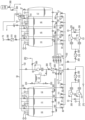
- Fig. 1 shows the tank system of a submarine according to the invention.
- the tank system has eight tanks 10, 11, 12, 13, 14, 15, 16, 17, with one tank 13 being designed as a degassing tank.
- the eight tanks 10, 11, 12, 13, 14, 15, 16, 17 are designed according to shipbuilding technology, with four tanks arranged on the starboard side and four tanks on the port side.
- the seven tanks 10, 11, 12, 14, 15, 16, 17 can be filled with methanol or water. Before leaving the harbor, for example, six tanks 10, 11, 12, 14, 15, 16 are fully filled with methanol as fuel, while one tank 17 contains water, although the fill level is low.
- the tanks 10, 11, 12, 14, 15, 16, 17 are connected to outlet valves 20, 21, 22, 24, 25, 26, 27. Furthermore, the tanks 10, 11, 12, 14, 15, 16, 17 are connected to inlet valves 30, 31, 32, 34, 35, 36, 37.
- the outlet valves 20, 21, 22, 24, 25, 26, 27 are connected to one another via an outlet connection 40, and the inlet valves 30, 31, 32, 34, 35, 36, 37 are connected to one another via an inlet connection 50.
- the outlet connection 40 is connected to the inlet connection 50 via a pump 60. This makes it possible to transfer methanol or water from any tank to any other tank, for example to trim the boat.
- Methanol can be conveyed into the inlet connection 50 via the refueling coupling 70 and into the tanks 10, 11, 12, 14, 15, 16, 17 via the inlet connection 50 and the inlet valves 30, 31, 32, 34, 35, 36, 37.
- the refueling coupling 70 is preferably arranged so that that the submarine can be easily refueled, for example the refueling coupling 70 is located in the turret.
- Tanks 10, 11, 12, 14, 15, 16, 17 are connected to methanol discharge valves 80, 81, 82, 84, 85, 86, 87.
- the methanol discharge valves 80, 81, 82, 84, 85, 86, 87 are interconnected via a methanol discharge connection 90. This allows methanol to be pumped from tanks 10, 11, 12, 14, 15, 16, 17 to a first reformer 200 by means of a pump 100. In the example shown, methanol can be pumped to a second reformer 210 via a further pump 101.
- the redundant design increases the reliability of the energy supply.
- Tanks 10, 11, 12, 14, 15, 16, 17 are connected to water drain valves 110, 111, 112, 114, 115, 116, 117.
- the water drain valves 110, 111, 112, 114, 115, 116, 117 are interconnected via a water drain connection 150. This allows water from tanks 10, 11, 12, 14, 15, 16, 17 to be pumped to a first reformer 20 by means of a pump 120.
- methanol can be pumped to a second reformer 230 via a further pump 121.
- the redundant design increases the reliability of the energy supply.
- Inert gas can be supplied from an inert gas supply 130 into the tanks 10, 11, 12, 14, 15, 16, 17 via an inert gas line 132.
- An inert gas control system 134 is preferably used for control.
- Tanks 140, 141, 142, 143, and 144 are connected by overflows 140, 141, 142, 143, and 144.
- the arrangement of overflows 140, 141, 142, 143, and 144 ensures that water and methanol cannot flow from one tank to the other, even when the submarine is tilted.
- an overflow connects two adjacent tanks at the top, each on the side opposite the adjacent tank.
- one outgoing connection below each tank can be closed by means of a manual shut-off valve 300.
- filters 310 can be integrated at various locations.
- a manual shut-off valve 300 is located at the inlet and outlet of the filter 310.
- a defueling coupling 260 is provided for discharging water.
- This defueling coupling 260 is preferably arranged behind the outlet connection 40 and the pump 60 so that water, but also methanol, can be brought from the submarine via the outlet connection 40 and the pump 60 to empty the tanks 140, 141, 142, 143, 144.
- methanol which has not been fully converted in the reformer can be recycled via a compound 270.
Landscapes
- Engineering & Computer Science (AREA)
- Life Sciences & Earth Sciences (AREA)
- Manufacturing & Machinery (AREA)
- Sustainable Development (AREA)
- Sustainable Energy (AREA)
- Chemical & Material Sciences (AREA)
- Chemical Kinetics & Catalysis (AREA)
- Electrochemistry (AREA)
- General Chemical & Material Sciences (AREA)
- Mechanical Engineering (AREA)
- Aviation & Aerospace Engineering (AREA)
- Fuel Cell (AREA)
Description
- Die Erfindung betrifft ein Unterseeboot, wobei das Unterseeboot Energie mittels einer Brennstoffzelle erzeugt, wobei der für die Brennstoffzelle notwendige Wasserstoff in einem Reformer aus Methanol gewonnen wird. Zur Lagerung des Methanols und des Wassers weist das Unterseeboot wenigstens drei Tanks auf in welchen wechselweise Methanol bzw. Wasser gelagert wird.
- Im Bereich nicht nuklearbetriebener Unterseeboote ist die Verwendung von Brennstoffzellen bekannt, beispielsweise die Klasse 212 A. Der für den Betrieb der Brennstoffzelle benötigte Wasserstoff wird in Metallhydridspeichern gelagert.
- Metallhydridspeicher haben sich für Boote mit einer Verdrängung von etwa 2000 t als sehr gut einsetzbar erwiesen. Für Boote mit einer deutlich höheren Verdrängung kann es jedoch effizienter sein, zusätzlich oder anstelle der Metallhydridspeicher einen Reformer in das Boot zu integrieren und dafür Methanol in kompakter Lagerform mitzuführen.
- Während des Einsatzes werden Methanol und Sauerstoff verbraucht und Wasser und Kohlendioxid erzeugt. Werden erzeugtes Wasser und Kohlendioxid aus dem Boot ausgebracht, so verringert sich das Gewicht, der Auftrieb des Bootes verändert sich dadurch. Um dieses zu kompensieren müsste Ballastwasser aufgenommen werden.
- Aus der
US 6 063 515 A ist eine Methode zum Betrieb eines Brennstoffzellensystems bekannt. - Aufgabe der Erfindung ist es, ein Unterseeboot zu schaffen, welches Methanol als Brennstoff mitnimmt und eine möglichst geringe Veränderung des Auftrieb beim Verbrauch des Methanol aufweist.
- Gelöst wird diese Aufgabe durch das Unterseeboot mit den in Anspruch 1 angegebenen Merkmalen, sowie durch das Verfahren mit den in Anspruch 12 angegebenen Merkmalen. Vorteilhafte Weiterbildungen ergeben sich aus den Unteransprüchen, der nachfolgenden Beschreibung sowie der Zeichnung.
- Das erfindungsgemäße Unterseeboot weist wenigstens eine erste Brennstoffzelle und wenigstens einen ersten Reformer auf. Der wenigstens eine erste Reformer ist zur Herstellung von Wasserstoff aus Methanol ausgebildet. Das Unterseeboot weist wenigstens einen ersten Tank, einen zweiten Tank und einen dritten Tank auf. Der erste Tank ist mit dem Reformer für Fluidtransport verbindbar, der zweite Tank ist mit dem Reformer für Fluidtransport verbindbar und der dritte Tank ist mit dem Reformer für Fluidtransport verbindbar. Weiter ist der erste Tank mit dem zweiten Tank für Fluidtransport verbindbar, der erste Tank ist mit dem dritten Tank für Fluidtransport verbindbar und der zweite Tank ist mit dem dritten Tank für Fluidtransport verbindbar.
- Zur Herstellung von Wasserstoff aus Methanol muss der Reformer sowohl mit Methanol als auch mit Wasser versorgt werden. Um dieses effizient tun zu können weist das Unterseeboot wenigstens drei Tanks auf, vorzugsweise mehr als drei Tanks. In diesen Tanks kann Methanol oder Wasser gelagert werden. Da es somit keine definierten Methanollagertanks und Wasserlagertanks gibt, muss jeder Tank mit dem Reformer verbunden sein. Zusätzlich ist es notwendig Fluide auch von einem in den anderen Tank umpumpen zu können, so dass jeder Tank mit jedem anderen Tank verbindbar ist.
- Im Sinne der Erfindung ist mit Wasser insbesondere Prozesswasser gemeint, das im Zusammenhang mit dem Betrieb des Reformers oder der Brennstoffzelle benötigt oder erzeugt wird. Das an Bord mitgeführte Trinkwasser ist hiervon zu unterscheiden. Im Regelfall weist Wasser im Sinne der Erfindung Verunreinigungen auf, insbesondere Methanol, es ist kein chemisch reines Wasser gemeint.
- Typischerweise wird vor Abfahrt eines Schiffes ein Tank Wasser aufweisen, alle anderen Tanks werden mit Methanol gefüllt sein. Vorzugsweise ist der Tank, welcher Wasser aufweist, zu einem geringen Anteil gefüllt, sodass dieser Tank entstehendes Reaktionswasser und Kondensat vom Reformer und/oder der Brennstoffzelle aufnehmen kann. Während der Fahrt wird Methanol entnommen und sobald ein Tank, in welchem Methanol gelagert war, leer ist, wird in diesen entstehendes Reaktionswasser und Kondensat vom Reformer und/oder der Brennstoffzelleeingeleitet.
- Hierdurch kann die Lagerung beider Fluide, Methanol und Wasser, in sehr kompakter Weise erfolgen. Gleichzeitig kann der Auftrieb des Unterseebootes beim Betrieb nahezu konstant gehalten werden.
- Erfindungsgemäß ist der erste Tank an der Unterseite mit einem ersten Auslassventil und an der Oberseite mit einem ersten Einlassventil verbunden. Der zweite Tank ist an der Unterseite mit einem zweiten Auslassventil und an der Oberseite mit einem zweiten Einlassventil verbunden. Der dritte Tank ist an der Unterseite mit einem dritten Auslassventil und an der Oberseite mit einem dritten Einlassventil verbunden.
- Bevorzugt ist jeder Tank mit einem einzigen Einlassventil auf der Oberseite für den Transport von Methanol und/oder Wasser versehen.
- Erfindungsgemäß sind das erste Auslassventil, das zweite Auslassventil und das dritte Auslassventil über eine Auslassverbindung verbunden.
- Erfindungsgemäß sind das erste Einlassventil, das zweite Einlassventil und das dritte Einlassventil über eine Einlassverbindung verbunden.
- Erfindungsgemäß sind die Einlassverbindung und die Auslassverbindung über eine Pumpe miteinander verbunden. Hierdurch kann besonders einfach und mit nur einem einzigen aktiven Pumpelement Flüssigkeit aus jedem Tank in jeden anderen Tank befördert werden.
- In einer weiteren Ausführungsform der Erfindung ist die Einlassverbindung mit einer Betankungskupplung verbunden. Über die Betankungskupplung kann Methanol oder Wasser in die Einlassverbindung und über die Einlassverbindung in einen ausgewählten Tank befördert werden.
- Erfindungsgemäß ist der erste Tank an der Unterseite mit einem ersten Methanolablassventil verbunden. Der zweite Tank ist an der Unterseite mit einem zweiten Methanolablassventil verbunden und der dritte Tank ist an der Unterseite mit einem dritten Methanolablassventil verbunden.
- Erfindungsgemäß sind das erste Methanolablassventil, das zweite Methanolablassventil und das dritte Methanolablassventil über eine Methanolablassverbindung verbunden.
- Erfindungsgemäß ist die Methanolablassverbindung über wenigstens eine erste Methanolablasspumpe mit dem wenigstens einen ersten Reformer verbunden.
- Durch diesen Aufbau kann Methanol aus jedem Tank in den ersten Reformer befördert werden.
- Erfindungsgemäß ist der erste Tank an der Unterseite mit einem ersten Wasserablassventil verbunden. Der zweite Tank ist an der Unterseite mit einem zweiten Wasserablassventil verbunden. Der dritte Tank ist an der Unterseite mit einem dritten Wasserablassventil verbunden.
- Erfindungsgemäß sind das erste Wasserablassventil, das zweite Wasserablassventil und das dritte Wasserablassventil über eine Wasserablassverbindung verbunden.
- Erfindungsgemäß ist die Wasserablassverbindung über wenigstens eine erste Wasserablasspumpe mit dem wenigstens einen ersten Reformer verbunden.
- Durch diesen Aufbau kann Wasser aus jedem Tank in den ersten Reformer befördert werden.
- In einer besonders bevorzugten Ausdrucksform sind das Auslassventil, das Methanolablassventil und das Wasserablassventil eines Tank jeweils über eine gemeinsame Verbindung mit dem Tank verbunden, sodass an der Unterseite nur eine Öffnung für eine Verbindung zu den drei Ventilen vorhanden ist.
- In einer weiteren Ausführungsform der Erfindung sind der erste Tank, der zweite Tank und der dritte Tank gegenüber der Atmosphäre des Unterseeboots abgeschlossen, wobei das Unterseeboot eine Vorrichtung zur Einleitung von Inertgas in wenigstens den ersten Tank, den zweiten Tank und den dritten Tank aufweist. Da Methanol giftig ist, sollte Methanol nicht in gasförmiger Form in die Atmosphäre abgegeben werden. Dieses kann insbesondere durch eine Schutzgasatmosphäre erreicht werden. Gleichzeitig ist hierdurch auch ein Explosionsschutz gewährleistet.
- In einer weiteren Ausführungsform der Erfindung ist das Inertgas Stickstoff, Kohlendioxid, Helium, Neon, Argon oder ein Gemisch hieraus. Besonders bevorzugt wird Stickstoff, Kohlendioxid oder Argon verwendet, da diese Gase zu verschiedenen Zwecken an Bord eines Unterseeboots sein können.
- In einer weiteren Ausführungsform der Erfindung sind wenigstens zwei Tanks zueinander benachbart angeordnet. Die zwei zueinander benachbarten Tanks sind an der Oberseite mit einem Überlaufrohr verbunden, wobei die Verbindungen zwischen dem Überlaufrohr und den Tanks jeweils auf der dem benachbarten Tank gegenüberliegenden Seite angeordnet sind. Diese Anordnung stellt sicher, dass auch bei extremer Schräglage des Unterseeboots keine Flüssigkeit aus einem Tank in einen benachbarten Tank fließt.
- In einer weiteren Ausführungsform der Erfindung weist das Unterseeboot wenigstens einen Ausgasungstank auf. Das Wasser kann nach dem Ausgasen aus dem Ausgasungstank über die Einlassverbindung in einen ausgewählten Tank befördert werden.
- In einer weiteren Ausführungsform der Erfindung weist das Unterseeboot einen kathodenseitigen Wasserabscheider auf, wobei der kathodenseitige Wasserabscheider mit der Kathodenseite der wenigstens einen Brennstoffzelle verbunden ist, wobei der kathodenseitige Wasserabscheider mit dem Ausgasungstank verbunden ist. Reaktionswasser von der Kathodenseite der Brennstoffzelle wird zunächst in den Ausgasungstank befördert. Das Reaktionswasser von der Kathodenseite der Brennstoffzelle ist mit Sauerstoff angereichert. Dieser Sauerstoff kann im Ausgasungstank an die Atmosphäre abgegeben werden.
- Reaktionswasser von der Anodenseite der Brennstoffzelle fällt in deutlich geringerem Mengen an, da das Produkt auf der Kathodenseite anfällt. Da dieses Wasser aber Wasserstoff enthalten kann wird es vorzugsweise in einem getrennten Tank gelagert oder zur Befeuchtung des Wasserstoffstroms in der Zuführung zur Anodenseite der Brennstoffzelle verwendet.
- In einer weiteren Ausführungsform der Erfindung ist der Ausgasungstank mit dem Reformer zur Überführung von Kondensat aus dem Reformer in den Ausgasungstank verbunden.
- In einer weiteren Ausführungsform der Erfindung ist der Ausgasungstank mit der Atmosphäre des Unterseeboots verbunden. Da hier hauptsächlich Sauerstoff abgegeben wird, welcher von der Besatzung verbraucht wird, entstehen keine weiteren Anforderungen an Lagerung oder Entsorgung.
- In einer weiteren Ausführungsform der Erfindung weist das Unterseeboot eine gerade Anzahl an Tanks auf, wobei die eine Hälfte der Tanks auf der Steuerbordseite und die andere Hälfte der Tanks auf der Backbordseite angeordnet sind. In einer vorteilhaften Weiterbildung dieser Ausführungsform sind weist das Unterseeboot insgesamt acht Tanks auf, wobei vier Tanks auf der Steuerbordseite und vier Tanks auf der Backbordseite angeordnet sind. Besonders bevorzugt handelt es sich bei einem der Tanks um einen Ausgasungstank. Beim Verlassen des Hafens können somit sechs Tanks mit Methanol und ein Tank mit etwas Wasser gefüllt sein. Hieraus ergibt sich die effizienteste Platznutzung an Bord.
- In einer weiteren Ausführungsform weist das Unterseeboot einen Druckkörper auf und die Tanks sind außerhalb des Druckkörpers angeordnet. Bevorzugt sind diese zwischen dem Druckkörper des Unterseeboots und einer weiteren Verkleidung angeordnet. Besonders bevorzugt sind diese um einen weiteren Tank, insbesondere den Sauerstofftank herum angeordnet.
- In einer weiteren Ausführungsform der Erfindung weist jeder Tank nur einen Einlass für Flüssigkeiten auf der Oberseite und einen Auslass für Flüssigkeiten auf der Unterseite auf. Zusätzlich weist jeder Tank bevorzugt wenigstens einen Einlass für Schutzgas auf. Weiter bevorzugt weist jeder Tank wenigstens ein Überlaufrohr auf. Zusätzlich kann jeder Tank einen Sensor für den Füllstand und gegebenenfalls Druck- und/oder Temperatursensoren aufweisen.
- In einer weiteren Ausführungsform der Erfindung bildet der Druckkörper wenigstens einen Teil des Tanks.
- In einer weiteren Ausführungsform der Erfindung weist wenigstens ein Tank eine Blase auf, wobei die Blase zur Aufnahme von Flüssigkeit ausgebildet ist. Unter einer Blase wird eine flexible Vorrichtung zur Aufnahme von Flüssigkeit verstanden, welche üblicherweise aus einem Kunststoff gebildet ist. Die Blase vergrößert ihr Volumen, wenn Flüssigkeit hineingegeben wird bzw. verkleinert ihr Volumen, wenn Flüssigkeit entnommen wird. Durch die Blase kann ein Kontakt zwischen der Flüssigkeit und der Tankwand vermeiden werden. Vorteil der Verwendung einer Blase kann beispielsweise der Verzicht auf eine Schutzgasatmosphäre sein, da Methanoldämpfe nicht aus der Blase nach außen gelangen können.
- In einem weiteren Aspekt betrifft die Erfindung ein Verfahren zum Betreiben eines erfindungsgemäßen Unterseeboots. Der wenigstens eine erste Tank ist mit Methanol befüllt, der wenigstens eine zweite Tank ist mit Wasser befüllt. Methanol wird aus dem ersten Tank in wenigstens einen ersten Reformer befördert. Wasser wird aus dem zweiten Tank in den wenigstens einen ersten Reformer befördert. Reaktionswasser wird von der Brennstoffzelle in den zweiten Tank befördert wird. Kondensat wird vom Reformer in den zweiten Tank befördert. Hierbei muss das Reaktionswasser von der Brennstoffzelle bzw. das Kondensat vom Reformer nicht unmittelbar in den zweiten Tank befördert werden, sondern kann zunächst in einen Ausgasungstank und aus dem Ausgasungstank in den zweiten Tank befördert werden.
- In einer weiteren Ausführungsform der Erfindung wird Methanol aus dem ersten Tank entnommen, bis der Füllstand unter 5 % des Tankvolumens, bevorzugt unter 3 % des Tankvolumens, besonders bevorzugt unter 2 % des Tankvolumens ist, wobei der Füllstand über 1 % des Tankvolumens ist.
- Durch einen Mindestfüllstand wird ein Trockenlaufen der Pumpen verhindert.
- In einer weiteren Ausführungsform der Erfindung wird in den ersten Tank mit einem Füllstand von 1 bis 5 %, bevorzugt von 1 bis 3 %, besonders bevorzugt von 1 bis 2 % des Tankvolumens Methanol Reaktionswasser von der Brennstoffzelle und/oder Kondensat vom Reformer befördert.
- Vorteil bei dieser Vermischung ist, dass die Toxizität des Gemisches aus Wasser und Methanol ausreichend gering ist, sodass das Gemisch ohne weitere Aufreinigung in die Umgebung abgegeben werden kann.
- In einer weiteren Ausführungsform der Erfindung wird Wasser aus dem zweiten Tank entnommen, bis der Füllstand unter 5 % des Tankvolumens, bevorzugt unter 3 % des Tankvolumens, besonders bevorzugt unter 2 % des Tankvolumens ist, wobei der Füllstand über 1 % des Tankvolumens ist.
- Durch einen Mindestfüllstand wird ein Trockenlaufen der Pumpen verhindert.
- In einer weiteren Ausführungsform der Erfindung wird in den zweiten Tank mit einem Füllstand von 1 bis 5 %, bevorzugt von 1 bis 3 %, besonders bevorzugt von 1 bis 2 % des Tankvolumens Wasser Methanol befördert wird. Dieses Auffüllen erfolgt üblicher Weise durch Betanken von außen, beispielsweise im Hafen oder durch einen Einsatzgruppenversorger.
- Dieser Restgehalt an Wasser ist nicht störend, da die Stöchiometrie von Wasser zu Methanol im Reformer hierdurch nicht maßgeblich verändert wird. Außerdem stellt es ein Optimum zwischen maximal möglicher Lagermenge an Methanol und Trockenlaufschutz für die Pumpen dar.
- Nachfolgend ist das erfindungsgemäße Unterseeboot anhand eines in der Zeichnung dargestellten Ausführungsbeispiels näher erläutert.
- In Fig. 1 ist das Tanksystem eines erfindungsgemäßen Unterseeboots gezeigt. Das Tanksystem weist acht Tanks 10, 11, 12, 13, 14, 15, 16, 17 auf, wobei ein Tank 13 als Ausgasungstank ausgeführt ist. Die acht Tanks 10, 11, 12, 13, 14, 15, 16, 17 sind schiffbautechnisch ausgeführt, wobei vier Tanks Steuerbord und vier Tanks Backbord angeordnet sind. Die sieben Tanks 10, 11, 12, 14, 15, 16, 17 können mit Methanol oder Wasser gefüllt sein. Vor Verlassen des Hafens sind beispielsweise sechs Tanks 10, 11, 12, 14, 15, 16 mit Methanol als Treibstoff voll gefüllt, während ein Tank 17 Wasser enthält, wobei der Füllstand gering ist.
- Die Tanks 10, 11, 12, 14, 15, 16, 17 sind mit Auslassventil 20, 21, 22, 24, 25, 26, 27 verbunden. Weiter sind die Tanks 10, 11, 12, 14, 15, 16, 17 mit Einlassventilen 30, 31, 32, 34, 35, 36, 37 verbunden. Die Auslassventile 20, 21, 22, 24, 25, 26, 27 sind über eine Auslassverbindung 40 miteinander verbunden, die Einlassventile 30, 31, 32, 34, 35, 36, 37 sind über eine Einlassverbindung 50 miteinander verbunden. Die Auslassverbindung 40 ist über eine Pumpe 60 mit der Einlassverbindung 50 verbunden. Hierdurch ist möglich Methanol oder Wasser von einem beliebigen Tank in einen anderen beliebigen Tank zu befördern, um beispielsweise das Boot zu trimmen.
- Über die Betankungskupplung 70 kann Methanol in die Einlassverbindung 50 und über die Einlassverbindung 50 und die Einlassventile 30, 31, 32, 34, 35, 36, 37 in die Tanks 10, 11, 12, 14, 15, 16, 17 befördert werden. Die Betankungskupplung 70 ist vorzugsweise so angeordnet, dass das Unterseeboot leicht betankt werden kann, beispielsweise ist die Betankungskupplung 70 im Turm angeordnet.
- Die Tanks 10, 11, 12, 14, 15, 16, 17 sind mit Methanolablassventilen 80, 81, 82, 84, 85, 86, 87 verbunden, die Methanolablassventile 80, 81, 82, 84, 85, 86, 87 sind über eine Methanolablassverbindung 90 miteinander verbunden. Hierdurch kann Methanol aus den Tanks 10, 11, 12, 14, 15, 16, 17 mittels einer Pumpe 100 zu einem ersten Reformer 200 befördert werden. Im gezeigten Beispiel kann über eine weitere Pumpe 101 Methanol zu einem zweiten Reformer 210 befördert werden. Die redundante Ausführung erhöht die Sicherheit der Energieversorgung.
- Die Tanks 10, 11, 12, 14, 15, 16, 17 sind mit Wasserablassventilen 110, 111, 112, 114, 115, 116, 117 verbunden, die Wasserablassventile 110, 111, 112, 114, 115, 116, 117 sind über eine Wasserablassverbindung 150 miteinander verbunden. Hierdurch kann Wasser aus den Tanks10, 11, 12, 14, 15, 16, 17 mittels einer Pumpe 120 zu einem ersten Reformer einer 20 befördert werden. Im gezeigten Beispiel kann über eine weitere Pumpe 121 Methanol zu einem zweiten Reformer 230 befördert werden. Die redundante Ausführung erhöht die Sicherheit der Energieversorgung.
- Aus einem Inertgasvorrat 130 kann über eine Inertgasleitung 132 Inertgas in die Tanks 10, 11, 12, 14, 15, 16, 17 geleitet werden. Zur Regelung wird vorzugsweise eine Inertgasregelung 134 eingesetzt.
- Die Tanks 140, 141, 142, 143, 144 sind mittels Überläufen 140, 141, 142, 143, 144 verbunden. Durch die Anordnung der Überläufe 140, 141, 142, 143, 144 ist gewährleistet, dass auch bei Schräglage des Unterseebootes Wasser und Methanol nicht von einem in den anderen Tank gelangen können. Hierzu verbindet ein Überlauf zwei benachbarte Tanks an der Oberseite jeweils an der dem angrenzenden Tank entgegengesetzten Seite.
- Bevorzugt ist jeweils unterhalb jedes Tanks die eine ausgehende Verbindung mittels eines manuellen Absperrventils 300 verschließbar.
- Zum Schutz der Gesamtanlage können an verschiedenen Stellen Filter 310 integriert sein. Um die Filter 310 austauschen zu können, befindet sich jeweils am Eingang und Ausgang des Filters 310 ein manuelles Absperrventil 300.
- Um Wasser wieder abgeben zu können ist eine Enttankungskupplung 260 vorgesehen. Diese Enttankungskupplung 260 ist vorzugsweise so hinter der Auslassverbindung 40 und der Pumpe 60 angeordnet, dass über die Auslassverbindung 40 und die Pumpe 60 Wasser, aber auch Methanol, zur Entleerung der Tanks 140, 141, 142, 143, 144 vom Unterseeboot gebracht werden kann.
- Es kann vorgesehen sein, dass Methanol welches im Reformer nicht vollständig umgesetzt wurde über eine Verbindung 270 zurückgeführt werden kann.
-
- 10
- Tank
- 11
- Tank
- 12
- Tank
- 13
- Tank
- 14
- Tank
- 15
- Tank
- 16
- Tank
- 17
- Tank
- 20
- Auslassventil
- 21
- Auslassventil
- 22
- Auslassventil
- 24
- Auslassventil
- 25
- Auslassventil
- 26
- Auslassventil
- 27
- Auslassventil
- 30
- Einlassventil
- 31
- Einlassventil
- 32
- Einlassventil
- 34
- Einlassventil
- 35
- Einlassventil
- 36
- Einlassventil
- 37
- Einlassventil
- 40
- Auslassverbindung
- 50
- Einlassverbindung
- 60
- Pumpe
- 70
- Betankungskupplung
- 80
- Methanolablassventil
- 81
- Methanolablassventil
- 82
- Methanolablassventil
- 84
- Methanolablassventil
- 85
- Methanolablassventil
- 86
- Methanolablassventil
- 87
- Methanolablassventil
- 90
- Methanolablassverbindung
- 100
- Pumpe
- 101
- Pumpe
- 110
- Wasserablassventil
- 111
- Wasserablassventil
- 112
- Wasserablassventil
- 114
- Wasserablassventil
- 115
- Wasserablassventil
- 116
- Wasserablassventil
- 117
- Wasserablassventil
- 120
- Pumpe
- 121
- Pumpe
- 130
- Inertgasvorrat
- 132
- Inertgasleitung
- 134
- Inertgasregelung
- 140
- Überlauf
- 141
- Überlauf
- 142
- Überlauf
- 143
- Überlauf
- 144
- Überlauf
- 150
- Wasserablassverbindung
- 200
- zum ersten Reformer
- 210
- zum zweiten Reformer
- 220
- zum ersten Reformer
- 230
- zum zweiten Reformer
- 240
- von der Brennstoffzelle
- 250
- vom Reformer
- 260
- Enttankungskupplung
- 270
- vom Reformer
- 300
- manuelles Absperrventil
- 310
- Filter
Claims (16)
- Unterseeboot mit wenigstens einer ersten Brennstoffzelle und wenigstens einem ersten Reformer, wobei der wenigstens eine erste Reformer zur Herstellung von Wasserstoff aus Methanol ausgebildet ist, wobei das Unterseeboot wenigstens einen ersten Tank (10, 11, 12, 13, 14, 15, 16, 17), einen zweiten Tank (10, 11, 12, 13, 14, 15, 16, 17) und einen dritten Tank (10, 11, 12, 13, 14, 15, 16, 17) aufweist, wobei der erste Tank (10, 11, 12, 13, 14, 15, 16, 17) mit dem Reformer für Fluidtransport verbindbar ist, wobei der zweiten Tank (10, 11, 12, 13, 14, 15, 16, 17) mit dem Reformer für Fluidtransport verbindbar ist, wobei der dritte Tank (10, 11, 12, 13, 14, 15, 16, 17) mit dem Reformer für Fluidtransport verbindbar ist, wobei der erste Tank (10, 11, 12, 13, 14, 15, 16, 17) mit dem zweiten Tank (10, 11, 12, 13, 14, 15, 16, 17) für Fluidtransport verbindbar ist, wobei der erste Tank (10, 11, 12, 13, 14, 15, 16, 17) mit dem dritten Tank (10, 11, 12, 13, 14, 15, 16, 17) für Fluidtransport verbindbar ist, wobei der zweite Tank (10, 11, 12, 13, 14, 15, 16, 17) mit dem dritten Tank (10, 11, 12, 13, 14, 15, 16, 17) für Fluidtransport verbindbar ist, wobei der erste Tank (10, 11, 12, 13, 14, 15, 16, 17) an der Unterseite mit einem ersten Auslassventil (20, 21, 22, 23, 24, 25, 26, 27) verbunden ist, dass der erste Tank (10, 11, 12, 13, 14, 15, 16, 17) an der Oberseite mit einem ersten Einlassventil (30, 31, 32, 33, 34, 35, 36, 37) verbunden ist, dass der zweite Tank (10, 11, 12, 13, 14, 15, 16, 17) an der Unterseite mit einem zweiten Auslassventil (20, 21, 22, 23, 24, 25, 26, 27) verbunden ist, dass der zweiten Tank (10, 11, 12, 13, 14, 15, 16, 17) an der Oberseite mit einem zweiten Einlassventil (30, 31, 32, 33, 34, 35, 36, 37) verbunden ist, dass der dritte Tank (10, 11, 12, 13, 14, 15, 16, 17) an der Unterseite mit einem dritten Auslassventil (20, 21, 22, 23, 24, 25, 26, 27) verbunden ist und dass der dritte Tank (10, 11, 12, 13, 14, 15, 16, 17) an der Oberseite mit einem dritten Einlassventil (30, 31, 32, 33, 34, 35, 36, 37) verbunden ist, dadurch gekennzeichnet, dass das erste Auslassventil (20, 21, 22, 23, 24, 25, 26, 27), das zweite Auslassventil (20, 21, 22, 23, 24, 25, 26, 27) und des dritte Auslassventil (20, 21, 22, 23, 24, 25, 26, 27) über eine Auslassverbindung (40) verbunden sind, wobei das erste Einlassventil (30, 31, 32, 33, 34, 35, 36, 37), das zweite Einlassventil (30, 31, 32, 33, 34, 35, 36, 37) und das dritte Einlassventil (30, 31, 32, 33, 34, 35, 36, 37) über eine Einlassverbindung (50) verbunden sind, wobei die Einlassverbindung (50) und die Auslassverbindung (40) über eine Pumpe (60, 101, 101, 120, 121) miteinander verbunden sind, wobei der erste Tank (10, 11, 12, 13, 14, 15, 16, 17) an der Unterseite mit einem ersten Methanolablassventil (80, 81, 82, 83, 84, 85, 86, 87) verbunden ist, dass der zweite Tank (10, 11, 12, 13, 14, 15, 16, 17) an der Unterseite mit einem zweiten Methanolablassventil (80, 81, 82, 83, 84, 85, 86, 87) verbunden ist und dass der dritte Tank (10, 11, 12, 13, 14, 15, 16, 17) an der Unterseite mit einem dritten Methanolablassventil (80, 81, 82, 83, 84, 85, 86, 87) verbunden ist, wobei das erste Methanolablassventil (80, 81, 82, 83, 84, 85, 86, 87), das zweite Methanolablassventil (80, 81, 82, 83, 84, 85, 86, 87) und das dritte Methanolablassventil (80, 81, 82, 83, 84, 85, 86, 87) über eine Methanolablassverbindung (90) verbunden sind, wobei die Methanolablassverbindung (90) über wenigstens eine erste Methanolablasspumpe mit dem wenigstens einen ersten Reformer verbunden ist, wobei der erste Tank (10, 11, 12, 13, 14, 15, 16, 17) an der Unterseite mit einem ersten Wasserablassventil (110, 111, 112, 113, 114, 115, 116, 117) verbunden ist, dass der zweite Tank (10, 11, 12, 13, 14, 15, 16, 17) an der Unterseite mit einem zweiten Wasserablassventil (110, 111, 112, 113, 114, 115, 116, 117) verbunden ist und dass der dritte Tank (10, 11, 12, 13, 14, 15, 16, 17) an der Unterseite mit einem dritten Wasserablassventil (110, 111, 112, 113, 114, 115, 116, 117) verbunden ist, wobei das erste Wasserablassventil (110, 111, 112, 113, 114, 115, 116, 117), das zweite Wasserablassventil (110, 111, 112, 113, 114, 115, 116, 117) und das dritte Wasserablassventil (110, 111, 112, 113, 114, 115, 116, 117) über eine Wasserablassverbindung (150) verbunden sind, wobei die Wasserablassverbindung (150) über wenigstens eine erste Wasserablasspumpe mit dem wenigstens einen ersten Reformer verbunden ist.
- Unterseeboot nach Anspruch 1, dadurch gekennzeichnet, dass die Einlassverbindung (50) mit einer Betankungskupplung (70) verbunden ist.
- Unterseeboot nach einem der vorhergehenden Ansprüche, dadurch gekennzeichnet, dass der erste Tank (10, 11, 12, 13, 14, 15, 16, 17), der zweite Tank (10, 11, 12, 13, 14, 15, 16, 17) und der dritte Tank (10, 11, 12, 13, 14, 15, 16, 17) gegenüber der Atmosphäre des Unterseeboots abgeschlossen sind, wobei das Unterseeboot eine Vorrichtung zur Einleitung von Inertgas in wenigstens den ersten Tank (10, 11, 12, 13, 14, 15, 16, 17), den zweiten Tank (10, 11, 12, 13, 14, 15, 16, 17) und den dritten Tank (10, 11, 12, 13, 14, 15, 16, 17) aufweist.
- Unterseeboot nach Anspruch 3, dadurch gekennzeichnet, dass das Inertgas Stickstoff, Kohlendioxid, Helium, Neon, Argon oder ein Gemisch hieraus ist.
- Unterseeboot nach einem der vorhergehenden Ansprüche, dadurch gekennzeichnet, dass wenigstens zwei Tanks (10, 11, 12, 13, 14, 15, 16, 17) zueinander benachbart angeordnet sind, wobei die zwei zueinander benachbarten Tanks (10, 11, 12, 13, 14, 15, 16, 17) an der Oberseite mit einem Überlaufrohr verbunden sind, wobei die Verbindungen zwischen dem Überlaufrohr und den Tanks (10, 11, 12, 13, 14, 15, 16, 17) jeweils auf der dem benachbarten Tank (10, 11, 12, 13, 14, 15, 16, 17) gegenüberliegenden Seite angeordnet sind.
- Unterseeboot nach einem der vorhergehenden Ansprüche, dadurch gekennzeichnet, dass das Unterseeboot wenigstens einen Ausgasungstank aufweist.
- Unterseeboot nach Anspruch 6, dadurch gekennzeichnet, dass das Unterseeboot einen kathodenseitigen Wasserabscheider aufweist, wobei der kathodenseitige Wasserabscheider mit der Kathodenseite der wenigstens einen Brennstoffzelle verbunden ist, wobei der kathodenseitige Wasserabscheider mit dem Ausgasungstank verbunden ist.
- Unterseeboot nach einem der Ansprüche 6 oder 7, dadurch gekennzeichnet, dass der Ausgasungstank mit dem Reformer zur Überführung von Kondensat aus dem Reformer in den Ausgasungstank verbunden ist.
- Unterseeboot nach einem der Ansprüche 6 bis 8, dadurch gekennzeichnet, dass der Ausgasungstank mit der Atmosphäre des Unterseeboots verbunden ist.
- Unterseeboot nach einem der vorhergehenden Ansprüche, dadurch gekennzeichnet, dass das Unterseeboot insgesamt acht Tanks (10, 11, 12, 13, 14, 15, 16, 17) aufweist, wobei vier Tanks (10, 11, 12, 13, 14, 15, 16, 17) auf der Steuerbordseite und vier Tanks (10, 11, 12, 13, 14, 15, 16, 17) auf der Backbordseite angeordnet sind.
- Unterseeboot nach einem der vorhergehenden Ansprüche, dadurch gekennzeichnet, dass jeder Tank (10, 11, 12, 13, 14, 15, 16, 17) nur einen Einlass für Flüssigkeiten auf der Oberseite und einen Auslass für Flüssigkeiten auf der Unterseite aufweist.
- Verfahren zum Betreiben eines Unterseeboots nach einem der vorhergehenden Ansprüche, wobei wenigstens ein erster Tank (10, 11, 12, 13, 14, 15, 16, 17) mit Methanol befüllt ist, wobei wenigstens ein zweiter Tank (10, 11, 12, 13, 14, 15, 16, 17) mit Wasser befüllt ist, wobei Methanol aus dem ersten Tank (10, 11, 12, 13, 14, 15, 16, 17) in wenigstens einen ersten Reformer befördert wird, wobei Wasser aus dem zweiten Tank (10, 11, 12, 13, 14, 15, 16, 17) in den wenigstens einen ersten Reformer befördert wird, wobei Reaktionswasser von der Brennstoffzelle in den zweiten Tank (10, 11, 12, 13, 14, 15, 16, 17) befördert wird, wobei Kondensat vom Reformer in den zweiten Tank (10, 11, 12, 13, 14, 15, 16, 17) befördert wird.
- Verfahren nach Anspruch 12, dadurch gekennzeichnet, dass Methanol aus dem ersten Tank (10, 11, 12, 13, 14, 15, 16, 17) entnommen wird, bis der Füllstand unter 5 % des Tankvolumens, bevorzugt unter 3 % des Tankvolumens, besonders bevorzugt unter 2 % des Tankvolumens ist, wobei der Füllstand über 1 % des Tankvolumens ist.
- Verfahren nach Anspruch 13, dadurch gekennzeichnet, dass in den ersten Tank (10, 11, 12, 13, 14, 15, 16, 17) mit einem Füllstand von 1 bis 5 %, bevorzugt von 1 bis 3 %, besonders bevorzugt von 1 bis 2 % des Tankvolumens Methanol Reaktionswasser von der Brennstoffzelle und/oder Kondensat vom Reformer befördert wird.
- Verfahren nach einem der Ansprüche 12 bis 14, dadurch gekennzeichnet, dass Wasser aus dem zweiten Tank (10, 11, 12, 13, 14, 15, 16, 17) entnommen wird, bis der Füllstand unter 5 % des Tankvolumens, bevorzugt unter 3 % des Tankvolumens, besonders bevorzugt unter 2 % des Tankvolumens ist, wobei der Füllstand über 1 % des Tankvolumens ist.
- Verfahren nach Anspruch 15, dadurch gekennzeichnet, dass in den zweiten Tank (10, 11, 12, 13, 14, 15, 16, 17) mit einem Füllstand von 1 bis 5 %, bevorzugt von 1 bis 3 %, besonders bevorzugt von 1 bis 2 % des Tankvolumens Wasser Methanol befördert wird.
Applications Claiming Priority (2)
| Application Number | Priority Date | Filing Date | Title |
|---|---|---|---|
| DE102016212186.3A DE102016212186A1 (de) | 2016-07-05 | 2016-07-05 | Tanksystem für ein Unterseeboot mit Brennstoffzelle |
| PCT/EP2017/066514 WO2018007326A1 (de) | 2016-07-05 | 2017-07-03 | Tanksystem für ein unterseeboot mit brennstoffzelle |
Publications (3)
| Publication Number | Publication Date |
|---|---|
| EP3481715A1 EP3481715A1 (de) | 2019-05-15 |
| EP3481715B1 true EP3481715B1 (de) | 2025-03-19 |
| EP3481715C0 EP3481715C0 (de) | 2025-03-19 |
Family
ID=59270042
Family Applications (1)
| Application Number | Title | Priority Date | Filing Date |
|---|---|---|---|
| EP17734740.8A Active EP3481715B1 (de) | 2016-07-05 | 2017-07-03 | Tanksystem für ein unterseeboot mit brennstoffzelle |
Country Status (5)
| Country | Link |
|---|---|
| EP (1) | EP3481715B1 (de) |
| KR (1) | KR102159889B1 (de) |
| AU (1) | AU2017294424B2 (de) |
| DE (1) | DE102016212186A1 (de) |
| WO (1) | WO2018007326A1 (de) |
Families Citing this family (3)
| Publication number | Priority date | Publication date | Assignee | Title |
|---|---|---|---|---|
| FR3091417B1 (fr) * | 2018-12-26 | 2025-10-10 | Naval Group | Système de piles à combustible pour un navire |
| DE102019213991A1 (de) * | 2019-09-13 | 2020-09-03 | Thyssenkrupp Ag | Betankung eines Unterseeboots auf hoher See |
| CN117646871A (zh) * | 2024-01-16 | 2024-03-05 | 江南造船(集团)有限责任公司 | 一种甲醇燃料舱连接系统 |
Family Cites Families (9)
| Publication number | Priority date | Publication date | Assignee | Title |
|---|---|---|---|---|
| US953881A (en) * | 1906-10-31 | 1910-04-05 | Paul Winand | Method of maintaining equality of weight in submarine boats while in operation. |
| DE69126321T2 (de) * | 1990-11-23 | 1998-04-02 | Vickers Shipbuilding & Eng | Anwendung von brennstoffzellen in stromversorgungssystemen |
| US6376113B1 (en) * | 1998-11-12 | 2002-04-23 | Idatech, Llc | Integrated fuel cell system |
| US6063515A (en) * | 1997-12-22 | 2000-05-16 | Ballard Power Systems Inc. | Integrated fuel cell electric power generation system for submarine applications |
| KR100558908B1 (ko) * | 2005-02-17 | 2006-03-10 | 대우조선해양 주식회사 | 반응물탱크의 공유구조를 갖는 잠수함 |
| JP2008298103A (ja) * | 2007-05-29 | 2008-12-11 | Fujitsu Ten Ltd | 制御装置、燃料ガス供給システム、及び燃料ガス容器 |
| DE102008013150B4 (de) * | 2008-03-07 | 2012-01-26 | Airbus Operations Gmbh | Mischsystem und Verfahren zur Inertisierung eines Gasvolumens sowie deren Verwendung |
| DE102009040379B3 (de) * | 2009-09-07 | 2011-07-28 | Howaldtswerke-Deutsche Werft GmbH, 24143 | Unterseeboot mit einem Verdichter |
| KR101572982B1 (ko) * | 2014-03-27 | 2015-11-30 | 대우조선해양 주식회사 | 연료전지를 탑재한 선박의 폐열 회수 시스템 |
-
2016
- 2016-07-05 DE DE102016212186.3A patent/DE102016212186A1/de not_active Withdrawn
-
2017
- 2017-07-03 WO PCT/EP2017/066514 patent/WO2018007326A1/de not_active Ceased
- 2017-07-03 EP EP17734740.8A patent/EP3481715B1/de active Active
- 2017-07-03 KR KR1020197000201A patent/KR102159889B1/ko active Active
- 2017-07-03 AU AU2017294424A patent/AU2017294424B2/en active Active
Also Published As
| Publication number | Publication date |
|---|---|
| AU2017294424B2 (en) | 2019-08-22 |
| EP3481715A1 (de) | 2019-05-15 |
| KR20190015498A (ko) | 2019-02-13 |
| WO2018007326A1 (de) | 2018-01-11 |
| AU2017294424A1 (en) | 2019-02-21 |
| EP3481715C0 (de) | 2025-03-19 |
| KR102159889B1 (ko) | 2020-09-25 |
| DE102016212186A1 (de) | 2018-01-25 |
Similar Documents
| Publication | Publication Date | Title |
|---|---|---|
| CN101522576B (zh) | 船舶压载水处理装置 | |
| DE69631062T2 (de) | Schiffsgestütztes system für den transport von druck-erdgas | |
| EP3481715A1 (de) | Tanksystem für ein unterseeboot mit brennstoffzelle | |
| EP3799667B1 (de) | Verfahren zur behandlung wasserstoffhaltiger und sauerstoffhaltiger restgase von brennstoffzellen sowie restgasbehandlungssystem | |
| DE2165388B1 (de) | Verfahren und vorrichtung zum entleeren von fluessiggasspeicherbehaeltern | |
| DE2324709A1 (de) | Rettungseinrichtung fuer unterwasserfahrzeuge | |
| DE69306391T2 (de) | Gerät zur herstellung von erdölprodukten auf see | |
| DE102019202190A1 (de) | Trimmsystem für ein modulares Unterwasserfahrzeug | |
| CN1997599A (zh) | 压载水系统 | |
| WO2012168334A1 (de) | Unterseeboot | |
| DE1506247C3 (de) | Verfahren zum Beladen und Entladen eines Ladungstanks in einem Öltanker | |
| EP3927615A1 (de) | Auftriebsmodifikationsmodul für ein modulares unterwasserfahrzeug | |
| DE102012207577A1 (de) | Abgabevorrichtung für kryogene Flüssigkeiten | |
| EP3003852B1 (de) | Antriebssystem für ein wasserfahrzeug, verfahren zum betrieb eines antriebssystems sowie wasserfahrzeug mit einem antriebssystem | |
| DE102009047117B4 (de) | Verfahren und System für das Entladen eines Ladetanks für kryogenes Flüssiggas | |
| DE102022210662A1 (de) | Wasserstofftank und Verfahren zum Betreiben eines Wasserstofftanks | |
| EP2534039A1 (de) | Seeschiff, insbesondere gasbetriebenes seeschiff | |
| DE4030018A1 (de) | Tankschiff | |
| DE102019213991A1 (de) | Betankung eines Unterseeboots auf hoher See | |
| DE102024139477B3 (de) | System zum Entnehmen von kryogenem Flüssiggas aus einem Schiffstank, betreffendes Schiff, Verwendung und Verfahren | |
| DE102023110093B3 (de) | Verfahren zum Entleeren eines Leitungsabschnitts eines Transfersystems sowie betreffendes Transfersystem | |
| DE2609470C2 (de) | Verfahren und Vorrichtung zur Versorgung mit Wasser von wasserarmen Gebieten | |
| DE2133674A1 (de) | Frachtschiff | |
| EP4612748A1 (de) | Brennstoffleitvorrichtung zum leiten eines brennstoffs, brennstoffzellenanordnung und wasserfahrzeug | |
| DE102007011671B4 (de) | Vorrichtung und Verfahren für die Regelung und Überwachung der Ballastwassertankspülung auf Schiffen |
Legal Events
| Date | Code | Title | Description |
|---|---|---|---|
| STAA | Information on the status of an ep patent application or granted ep patent |
Free format text: STATUS: UNKNOWN |
|
| STAA | Information on the status of an ep patent application or granted ep patent |
Free format text: STATUS: THE INTERNATIONAL PUBLICATION HAS BEEN MADE |
|
| PUAI | Public reference made under article 153(3) epc to a published international application that has entered the european phase |
Free format text: ORIGINAL CODE: 0009012 |
|
| STAA | Information on the status of an ep patent application or granted ep patent |
Free format text: STATUS: REQUEST FOR EXAMINATION WAS MADE |
|
| 17P | Request for examination filed |
Effective date: 20190205 |
|
| AK | Designated contracting states |
Kind code of ref document: A1 Designated state(s): AL AT BE BG CH CY CZ DE DK EE ES FI FR GB GR HR HU IE IS IT LI LT LU LV MC MK MT NL NO PL PT RO RS SE SI SK SM TR |
|
| AX | Request for extension of the european patent |
Extension state: BA ME |
|
| RAP1 | Party data changed (applicant data changed or rights of an application transferred) |
Owner name: THYSSENKRUPP AG Owner name: THYSSENKRUPP MARINE SYSTEMS GMBH |
|
| DAV | Request for validation of the european patent (deleted) | ||
| DAX | Request for extension of the european patent (deleted) | ||
| STAA | Information on the status of an ep patent application or granted ep patent |
Free format text: STATUS: EXAMINATION IS IN PROGRESS |
|
| 17Q | First examination report despatched |
Effective date: 20211104 |
|
| GRAP | Despatch of communication of intention to grant a patent |
Free format text: ORIGINAL CODE: EPIDOSNIGR1 |
|
| STAA | Information on the status of an ep patent application or granted ep patent |
Free format text: STATUS: GRANT OF PATENT IS INTENDED |
|
| INTG | Intention to grant announced |
Effective date: 20241211 |
|
| GRAS | Grant fee paid |
Free format text: ORIGINAL CODE: EPIDOSNIGR3 |
|
| GRAA | (expected) grant |
Free format text: ORIGINAL CODE: 0009210 |
|
| STAA | Information on the status of an ep patent application or granted ep patent |
Free format text: STATUS: THE PATENT HAS BEEN GRANTED |
|
| RAP3 | Party data changed (applicant data changed or rights of an application transferred) |
Owner name: THYSSENKRUPP AG Owner name: THYSSENKRUPP MARINE SYSTEMS GMBH |
|
| AK | Designated contracting states |
Kind code of ref document: B1 Designated state(s): AL AT BE BG CH CY CZ DE DK EE ES FI FR GB GR HR HU IE IS IT LI LT LU LV MC MK MT NL NO PL PT RO RS SE SI SK SM TR |
|
| REG | Reference to a national code |
Ref country code: GB Ref legal event code: FG4D Free format text: NOT ENGLISH |
|
| REG | Reference to a national code |
Ref country code: CH Ref legal event code: EP |
|
| REG | Reference to a national code |
Ref country code: DE Ref legal event code: R096 Ref document number: 502017016752 Country of ref document: DE |
|
| REG | Reference to a national code |
Ref country code: IE Ref legal event code: FG4D Free format text: LANGUAGE OF EP DOCUMENT: GERMAN |
|
| U01 | Request for unitary effect filed |
Effective date: 20250402 |
|
| U07 | Unitary effect registered |
Designated state(s): AT BE BG DE DK EE FI FR IT LT LU LV MT NL PT RO SE SI Effective date: 20250408 |
|
| U79 | Statement concerning licences of right filed [unitary effect] |
Effective date: 20250408 |
|
| PG25 | Lapsed in a contracting state [announced via postgrant information from national office to epo] |
Ref country code: RS Free format text: LAPSE BECAUSE OF FAILURE TO SUBMIT A TRANSLATION OF THE DESCRIPTION OR TO PAY THE FEE WITHIN THE PRESCRIBED TIME-LIMIT Effective date: 20250619 |
|
| PG25 | Lapsed in a contracting state [announced via postgrant information from national office to epo] |
Ref country code: NO Free format text: LAPSE BECAUSE OF FAILURE TO SUBMIT A TRANSLATION OF THE DESCRIPTION OR TO PAY THE FEE WITHIN THE PRESCRIBED TIME-LIMIT Effective date: 20250619 |
|
| PG25 | Lapsed in a contracting state [announced via postgrant information from national office to epo] |
Ref country code: HR Free format text: LAPSE BECAUSE OF FAILURE TO SUBMIT A TRANSLATION OF THE DESCRIPTION OR TO PAY THE FEE WITHIN THE PRESCRIBED TIME-LIMIT Effective date: 20250319 |
|
| PG25 | Lapsed in a contracting state [announced via postgrant information from national office to epo] |
Ref country code: GR Free format text: LAPSE BECAUSE OF FAILURE TO SUBMIT A TRANSLATION OF THE DESCRIPTION OR TO PAY THE FEE WITHIN THE PRESCRIBED TIME-LIMIT Effective date: 20250620 |
|
| U20 | Renewal fee for the european patent with unitary effect paid |
Year of fee payment: 9 Effective date: 20250728 |
|
| PG25 | Lapsed in a contracting state [announced via postgrant information from national office to epo] |
Ref country code: SM Free format text: LAPSE BECAUSE OF FAILURE TO SUBMIT A TRANSLATION OF THE DESCRIPTION OR TO PAY THE FEE WITHIN THE PRESCRIBED TIME-LIMIT Effective date: 20250319 |
|
| PG25 | Lapsed in a contracting state [announced via postgrant information from national office to epo] |
Ref country code: ES Free format text: LAPSE BECAUSE OF FAILURE TO SUBMIT A TRANSLATION OF THE DESCRIPTION OR TO PAY THE FEE WITHIN THE PRESCRIBED TIME-LIMIT Effective date: 20250319 |
|
| PG25 | Lapsed in a contracting state [announced via postgrant information from national office to epo] |
Ref country code: PL Free format text: LAPSE BECAUSE OF FAILURE TO SUBMIT A TRANSLATION OF THE DESCRIPTION OR TO PAY THE FEE WITHIN THE PRESCRIBED TIME-LIMIT Effective date: 20250319 |
|
| PG25 | Lapsed in a contracting state [announced via postgrant information from national office to epo] |
Ref country code: CZ Free format text: LAPSE BECAUSE OF FAILURE TO SUBMIT A TRANSLATION OF THE DESCRIPTION OR TO PAY THE FEE WITHIN THE PRESCRIBED TIME-LIMIT Effective date: 20250319 |
|
| PG25 | Lapsed in a contracting state [announced via postgrant information from national office to epo] |
Ref country code: SK Free format text: LAPSE BECAUSE OF FAILURE TO SUBMIT A TRANSLATION OF THE DESCRIPTION OR TO PAY THE FEE WITHIN THE PRESCRIBED TIME-LIMIT Effective date: 20250319 |
|
| PG25 | Lapsed in a contracting state [announced via postgrant information from national office to epo] |
Ref country code: IS Free format text: LAPSE BECAUSE OF FAILURE TO SUBMIT A TRANSLATION OF THE DESCRIPTION OR TO PAY THE FEE WITHIN THE PRESCRIBED TIME-LIMIT Effective date: 20250719 |
|
| PLBE | No opposition filed within time limit |
Free format text: ORIGINAL CODE: 0009261 |
|
| STAA | Information on the status of an ep patent application or granted ep patent |
Free format text: STATUS: NO OPPOSITION FILED WITHIN TIME LIMIT |
|
| REG | Reference to a national code |
Ref country code: CH Ref legal event code: L10 Free format text: ST27 STATUS EVENT CODE: U-0-0-L10-L00 (AS PROVIDED BY THE NATIONAL OFFICE) Effective date: 20260128 |
|
| REG | Reference to a national code |
Ref country code: CH Ref legal event code: H13 Free format text: ST27 STATUS EVENT CODE: U-0-0-H10-H13 (AS PROVIDED BY THE NATIONAL OFFICE) Effective date: 20260224 |
|
| 26N | No opposition filed |
Effective date: 20251222 |
|
| GBPC | Gb: european patent ceased through non-payment of renewal fee |
Effective date: 20250703 |
|
| PG25 | Lapsed in a contracting state [announced via postgrant information from national office to epo] |
Ref country code: GB Free format text: LAPSE BECAUSE OF NON-PAYMENT OF DUE FEES Effective date: 20250703 |
|
| PG25 | Lapsed in a contracting state [announced via postgrant information from national office to epo] |
Ref country code: CH Free format text: LAPSE BECAUSE OF NON-PAYMENT OF DUE FEES Effective date: 20250731 |