EP3481645B1 - Rad für industriefahrzeug - Google Patents
Rad für industriefahrzeug Download PDFInfo
- Publication number
- EP3481645B1 EP3481645B1 EP17821219.7A EP17821219A EP3481645B1 EP 3481645 B1 EP3481645 B1 EP 3481645B1 EP 17821219 A EP17821219 A EP 17821219A EP 3481645 B1 EP3481645 B1 EP 3481645B1
- Authority
- EP
- European Patent Office
- Prior art keywords
- section
- wheel
- cross
- angle
- outer annular
- Prior art date
- Legal status (The legal status is an assumption and is not a legal conclusion. Google has not performed a legal analysis and makes no representation as to the accuracy of the status listed.)
- Active
Links
Images




Classifications
-
- B—PERFORMING OPERATIONS; TRANSPORTING
- B60—VEHICLES IN GENERAL
- B60B—VEHICLE WHEELS; CASTORS; AXLES FOR WHEELS OR CASTORS; INCREASING WHEEL ADHESION
- B60B19/00—Wheels not otherwise provided for or having characteristics specified in one of the subgroups of this group
-
- B—PERFORMING OPERATIONS; TRANSPORTING
- B60—VEHICLES IN GENERAL
- B60B—VEHICLE WHEELS; CASTORS; AXLES FOR WHEELS OR CASTORS; INCREASING WHEEL ADHESION
- B60B21/00—Rims
- B60B21/02—Rims characterised by transverse section
- B60B21/021—Rims characterised by transverse section with inwardly directed flanges, i.e. the tyre-seat being reversed
-
- B—PERFORMING OPERATIONS; TRANSPORTING
- B60—VEHICLES IN GENERAL
- B60B—VEHICLE WHEELS; CASTORS; AXLES FOR WHEELS OR CASTORS; INCREASING WHEEL ADHESION
- B60B21/00—Rims
- B60B21/02—Rims characterised by transverse section
- B60B21/04—Rims characterised by transverse section with substantially radial flanges
-
- B—PERFORMING OPERATIONS; TRANSPORTING
- B60—VEHICLES IN GENERAL
- B60B—VEHICLE WHEELS; CASTORS; AXLES FOR WHEELS OR CASTORS; INCREASING WHEEL ADHESION
- B60B3/00—Disc wheels, i.e. wheels with load-supporting disc body
-
- B—PERFORMING OPERATIONS; TRANSPORTING
- B60—VEHICLES IN GENERAL
- B60B—VEHICLE WHEELS; CASTORS; AXLES FOR WHEELS OR CASTORS; INCREASING WHEEL ADHESION
- B60B3/00—Disc wheels, i.e. wheels with load-supporting disc body
- B60B3/002—Disc wheels, i.e. wheels with load-supporting disc body characterised by the shape of the disc
-
- B—PERFORMING OPERATIONS; TRANSPORTING
- B60—VEHICLES IN GENERAL
- B60B—VEHICLE WHEELS; CASTORS; AXLES FOR WHEELS OR CASTORS; INCREASING WHEEL ADHESION
- B60B3/00—Disc wheels, i.e. wheels with load-supporting disc body
- B60B3/02—Disc wheels, i.e. wheels with load-supporting disc body with a single disc body integral with rim
-
- B—PERFORMING OPERATIONS; TRANSPORTING
- B60—VEHICLES IN GENERAL
- B60B—VEHICLE WHEELS; CASTORS; AXLES FOR WHEELS OR CASTORS; INCREASING WHEEL ADHESION
- B60B9/00—Wheels of high resiliency, e.g. with conical interacting pressure-surfaces
-
- B—PERFORMING OPERATIONS; TRANSPORTING
- B62—LAND VEHICLES FOR TRAVELLING OTHERWISE THAN ON RAILS
- B62D—MOTOR VEHICLES; TRAILERS
- B62D55/00—Endless track vehicles
- B62D55/08—Endless track units; Parts thereof
- B62D55/096—Endless track units; Parts thereof with noise reducing means
- B62D55/0966—Low noise rollers, e.g. with antivibration means
-
- B—PERFORMING OPERATIONS; TRANSPORTING
- B60—VEHICLES IN GENERAL
- B60B—VEHICLE WHEELS; CASTORS; AXLES FOR WHEELS OR CASTORS; INCREASING WHEEL ADHESION
- B60B2360/00—Materials; Physical forms thereof
- B60B2360/10—Metallic materials
- B60B2360/102—Steel
-
- B—PERFORMING OPERATIONS; TRANSPORTING
- B60—VEHICLES IN GENERAL
- B60B—VEHICLE WHEELS; CASTORS; AXLES FOR WHEELS OR CASTORS; INCREASING WHEEL ADHESION
- B60B2900/00—Purpose of invention
- B60B2900/10—Reduction of
- B60B2900/111—Weight
-
- B—PERFORMING OPERATIONS; TRANSPORTING
- B60—VEHICLES IN GENERAL
- B60B—VEHICLE WHEELS; CASTORS; AXLES FOR WHEELS OR CASTORS; INCREASING WHEEL ADHESION
- B60B2900/00—Purpose of invention
- B60B2900/30—Increase in
- B60B2900/311—Rigidity or stiffness
-
- B—PERFORMING OPERATIONS; TRANSPORTING
- B60—VEHICLES IN GENERAL
- B60B—VEHICLE WHEELS; CASTORS; AXLES FOR WHEELS OR CASTORS; INCREASING WHEEL ADHESION
- B60B2900/00—Purpose of invention
- B60B2900/30—Increase in
- B60B2900/313—Resiliency
-
- B—PERFORMING OPERATIONS; TRANSPORTING
- B60—VEHICLES IN GENERAL
- B60B—VEHICLE WHEELS; CASTORS; AXLES FOR WHEELS OR CASTORS; INCREASING WHEEL ADHESION
- B60B2900/00—Purpose of invention
- B60B2900/50—Improvement of
- B60B2900/551—Handling of obstacles or difficult terrains
-
- B—PERFORMING OPERATIONS; TRANSPORTING
- B60—VEHICLES IN GENERAL
- B60B—VEHICLE WHEELS; CASTORS; AXLES FOR WHEELS OR CASTORS; INCREASING WHEEL ADHESION
- B60B2900/00—Purpose of invention
- B60B2900/70—Adaptation for
- B60B2900/711—High loads, e.g. by reinforcements
-
- B—PERFORMING OPERATIONS; TRANSPORTING
- B60—VEHICLES IN GENERAL
- B60B—VEHICLE WHEELS; CASTORS; AXLES FOR WHEELS OR CASTORS; INCREASING WHEEL ADHESION
- B60B2900/00—Purpose of invention
- B60B2900/70—Adaptation for
- B60B2900/721—Use under adverse external conditions
-
- B—PERFORMING OPERATIONS; TRANSPORTING
- B60—VEHICLES IN GENERAL
- B60B—VEHICLE WHEELS; CASTORS; AXLES FOR WHEELS OR CASTORS; INCREASING WHEEL ADHESION
- B60B2900/00—Purpose of invention
- B60B2900/70—Adaptation for
- B60B2900/731—Use in cases of damage, failure or emergency
-
- B—PERFORMING OPERATIONS; TRANSPORTING
- B60—VEHICLES IN GENERAL
- B60Y—INDEXING SCHEME RELATING TO ASPECTS CROSS-CUTTING VEHICLE TECHNOLOGY
- B60Y2200/00—Type of vehicle
- B60Y2200/60—Industrial applications, e.g. pipe inspection vehicles
-
- Y—GENERAL TAGGING OF NEW TECHNOLOGICAL DEVELOPMENTS; GENERAL TAGGING OF CROSS-SECTIONAL TECHNOLOGIES SPANNING OVER SEVERAL SECTIONS OF THE IPC; TECHNICAL SUBJECTS COVERED BY FORMER USPC CROSS-REFERENCE ART COLLECTIONS [XRACs] AND DIGESTS
- Y02—TECHNOLOGIES OR APPLICATIONS FOR MITIGATION OR ADAPTATION AGAINST CLIMATE CHANGE
- Y02T—CLIMATE CHANGE MITIGATION TECHNOLOGIES RELATED TO TRANSPORTATION
- Y02T10/00—Road transport of goods or passengers
- Y02T10/80—Technologies aiming to reduce greenhouse gasses emissions common to all road transportation technologies
- Y02T10/86—Optimisation of rolling resistance, e.g. weight reduction
Definitions
- This invention concerns wheels for industrial vehicles. More particularly, this invention concerns a wheel for scissor lift vehicles, aerial work platform vehicles, ground support equipment vehicles and similar industrial vehicles,
- Scissor lift and aerial platform vehicles are a type of industrial vehicle utilized in numerous interior and exterior applications to aid in reaching otherwise inaccessible areas.
- a scissor lift vehicle includes an extendable platform that can be extended vertically to a higher elevation.
- the wheels on such vehicles need to contribute to the maneuverability, mobility, and stability of the vehicle. Also such vehicles are often abused. For example, it is common that wheels on an industrial vehicle may be run into a curb or other obstacle or effectively dropped from a height for example by running the vehicle off of an incline or curb dropping to a lower surface rather abruptly and violently that can result in denting, bending or knocking out of round a conventional wheel.
- Document US 4 253 510 A discloses an integral tire having a wheel showing a radial body portion connecting the rim portion to the wheel axle having the shape of an open "V" turned inwards.
- Document WO2015150333A2 discloses a road wheel having a mounting disc, a dish-shaped transitional wall having an outer edge, a rim with an annular cylindrical wall attached along a first rim edge to the outer edge of the transitional wall, and a stiffening flange attached to the rim along a second rim edge opposite the first rim edge.
- This wheel shows a mounting disc disposed axially externally to the annular cylindrical wall. This known wheel does not provide improved stability and load transfer carrying capacity of the vehicle.
- the present invention presents a wheel design for a scissor lift, aerial platform vehicles, ground support equipment vehicles, and other industrial vehicles.
- the wheels on these vehicles must have the maneuverability to move to and accurately position at, under, or near the desired work location.
- a scissor lift vehicle is designed to extend, generally vertically, to reach otherwise inaccessible areas, thus changing the center of gravity as the platform extends.
- the present wheel design provides improved stability and load transfer carrying capacity of the vehicle, as well as other industrial vehicles. Further, it can be advantageous that the wheel have the flexibility to survive the various abusive situations that can result in damaging a conventional wheel.
- the present invention provides a wheel to be used with an industrial vehicle.
- the wheel is configured to provide improved maneuverability and/or flexibility to recover from incidences that can damage the wheel, for example running into a curb, or dropping from a height.
- the wheel provides a light weight structure, having strength to flex on impact and resist bending, allowing it to return to its original shape after impact.
- the wheel comprises a rim to be used with a rubber tire.
- the wheel can be a metal rim, for example a one piece metal wheel.
- the wheel can also be made of two or more pieces assembled together such as by welding.
- the vehicle can be an industrial vehicle such as a scissor lift, aerial work platform, forklift or other industrial vehicle.
- the wheel can be used for construction equipment, asphalt paving equipment airport ground support equipment and surface cleaning equipment vehicles.
- the wheel can be used on any industrial vehicle having a maximum speed of about 30 miles per hour.
- a wheel for an industrial vehicle is provided.
- it can be formed or fabricated in one piece.
- it can be formed of two or more pieces that can be assembled together, such as by welding the pieces together.
- the wheel comprises a substantially cylindrical wheel rim including opposed first and second annular edges and a rim base there between, the rim base having a substantially planar cross-section; a hub aperture; a surface extending radially from the hub aperture to the first annular edge of the wheel rim; and a back flange formed extending inwardly from the second annular edge of the wheel rim, the back flange formed at an angle with respect to the rim base, wherein the surface comprises a center hub section about the hub aperture, a transition section extending outwardly from the center hub section, and an outer annular face section extending outwardly from the transition section to the first annular edge of the wheel rim, and wherein the wheel has a longitudinal axis passing through hub aperture, the longitudinal axis being parallel to the longitudinal axis of an axle to which the wheel is configured to be mounted and a center line passing vertically through a cross-section of the wheel, the center line being equidistantly spaced between the first and second annular edges.
- the center hub section has a substantially planar cross-section and the outer annular face section has a substantially planar cross-section.
- the center hub section can have a substantially planar cross- section that lies on the vertical center line.
- the substantially planar cross-section of the center hub section and the substantially planar cross-section of the outer annular face section are substantially parallel to each other, and the center hub section can be offset from the center line outwardly towards the outer annular face section or inwardly towards the back flange.
- the substantially planar cross-section of the center hub section can lie on the center line.
- the substantially planar cross-section of the outer annular face section or the substantially planar cross-section of the center hub section or both can be substantially perpendicular to the substantially planar cross-section of the rim base.
- the transition section can have a substantially planar cross-section.
- the transition section can extend outwardly from the center hub section at an angle B and the angle B can be in the range of about 20 to about 85 degrees with respect to the center line.
- the outer annular face section can extend outwardly from the transition section at an angle C and the angle C can be in the range of about 120 to about 185 degrees with respect to the center line.
- the center hub section can extend outwardly from the hub aperture at an angle A of substantially 90° with respect to the longitudinal axis.
- the wheel can comprise a concave step between the outer annular face and the wheel rim.
- the wheel can comprise a convex large radius section between the outer annular face and the wheel rim.
- the wheel can comprise an angled section between the outer annular face and the wheel rim.
- the wheel can be a one piece design that is formed by stamping a metal piece.
- the metal piece can be steel, in one or more aspects, the thickness of the metal piece can be in the range of about 2 mm to about 4-5 mm or more. In various aspects the thickness of the metal piece can be at least 3 mm.
- the wheel rim can be designed to receive and secure in place a tire.
- the angle between the wheel rim and the back flange can be an angle F in the range of anywhere between about 45 degrees to about 135 degrees (or 90° plus or minus 45° or less) with respect to a planar surface of the rim base or with respect to the longitudinal axis or both.
- the back flange can have a length that is at least twice the thickness of the back flange.
- the industrial vehicle can be selected from the group consisting of a scissor lift vehicle, an aerial platform vehicle and other industrial vehicles, such as ground support equipment.
- Described below are various embodiments of the present systems and methods for a wheel for industrial vehicles, such as a scissor lift wheel. Although particular embodiments are described, those embodiments are mere exemplary implementations of the system and method.
- the present wheel is designed to attach to the hub of an axle of a vehicle, in particular an industrial vehicle, and is formed in one piece having a unique look, flexibility and strength, in an aspect, the wheel can be for use on a scissor lift vehicle an aerial platform vehicle, or ground support equipment.
- the wheel has a front side which faces away from the vehicle and a back side that faces toward the vehicle.
- the wheel can be made from a metal material, such as steel or a high strength metal material, in some aspects, the metal can be steel or aluminum, in some aspects the high strength material can be an alloy, or a high strength composite material.
- the wheel can be formed by stamped metal, spun metal, cast metal, flow-formed, or other metal-metal working processes, in various aspects, the stamped metal can have a thickness in the range of about 2mm or more, about 2,5mm or more, or about 3mm or more. In various aspects, the thickness of the stamped metal can have a thickness in the range of about 2mm to about 6mm, about 2.5mm to about 5.5mm, about 3mm to about 5mm, or anywhere in between, in any one or more aspects, the wheel diameter can be between 7 to 30 inches, and any range there between. For example, the wheel diameter can be between 8 to 30 inches, 9 to 30 inches, 10 to 30 inches, 12 to 28 inches, 14 to 26 inches, 16 to 24 inches, 18 to 22 inches, or about 20 inches. In other aspects, the wheel diameter can be greater than 30 inches.
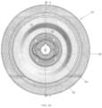
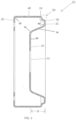
- RGs. 1A and 1 B illustrate an example of a wheel of the present invention.
- the wheel 20 includes a substantially cylindrical wheel rim 22 about the periphery of the wheel 20.
- the wheel rim 22 includes a first annular edge 24 an opposed second annular edge 26, and a rim base 48 there between extending from the first annular edge 24 to the second annular edge 26.
- the wheel 20 also has a front face surface 28 and an opposed back flange 30.
- the opposed back flange 30 extends inwardly from the wheel rim base 48 at the opposed second annular edge 28 towards an axle on which the wheel is configured to be mounted.
- the axle can have a longitudinal direction or axis 43.
- the front face surface 28 includes an outer annular face section 32 extending inwardly from the first annular edge 24 of the wheel rim base 48 leading to a transition section 34.
- Transition section 34 extends inwardly from the annular face section 32 to a center hub section 36 which is inwardly offset by an offset depth D from the annular face section 32 to the center hub section 36 by the transition section 34.
- the offset depth D of the center hub section 36 can be dependent on the specific use.
- an industrial vehicle such as a scissor lift vehicle
- the offset D is neutral at the wheel center line 37, the wheel center line running vertically through a cross-section of the wheel and being located equidistantiy between the first annular edge 24 and the second annular edge 26.
- the center hub section 36 is not neutral at the wheel center line 37 and, instead, can have an offset D closer to the annular face section 32 or closer to the back flange 30.
- the offset D can be plus or minus 30% of the distance between the center line 37 and either the annular face section 32 or the back flange 30 from the center line 37 towards either the annular face 32 or the back flange 30, or less.
- the offset D can be plus or minus 1 , 2 inches, or less, from the center line 37 towards either the annular face 32 or the back flange 30.
- the wheel 20 can have an annular corner profile 50 (see, e.g., Figs. 2 , 3B , 5 and 6 ) at the first annular edge 24 and the face exterior edge 38.
- the center hub section 36 extends outwardly from the longitudinal axis 43 at an angle A with respect to the longitudinal axis 43.
- the angle A at which the center hub section 36 extends outwardly from the longitudinal axis 43 is substantially 90°.
- the center hub section 36 can be substantially planar in cross-section, such as depicted in FIG. 1 B . In other aspects, which do not form part of the claimed inveniton, the center hub section need not be substantially planar in cross-section and maybe non-planar in cross-section.
- the center hub section 36 can contain bolt apertures 40 disposed radially about a hub aperture 42 within the center hub section 36. in some embodiments, there can be at least 3 bolt apertures, in some aspects, the bolt apertures 40 can be chamfered at a specified angle (as seen, e.g., in FIG. 1 B) . In other aspects, the bolt apertures 40 can be flush with the center hub section 36 (as seen, e.g., in HG. 2).
- the front face surface 28 can continue from a perimeter 44 of the center hub section 36 through the transition section 34 to an interior edge 46 of outer annular face section 32.
- the hub perimeter 44 thus provides a first transition angle B between center hub section 36 and transition section 34, the interior edge 46 providing a second transition angle for transition section 34.
- the front face surface 28 can continue from the center hub perimeter 44 through the transition section 34 at an angle B that is less than 90° with respect to center line 37.
- angle B can range from 5° to 60° or anywhere in between, for example from 20° to 55°, 25° to 50°, 30° to 45°, etc.
- transition section 34 can be a substantially planar in cross-section, such as depicted in FIG.
- the front face surface 28 can continue from the transition section 34 through the interior edge 46 of outer annular face section 32 at an angle C that is greater than 90° with respect to the planar cross-section of transition section 34, In any one or more aspects, angle C can range from 120° to 165°, or anywhere in between, for example 125° to 180°, or 130° to 155°, etc., with respect to a planar face of the outer annular face section 32 parallel to the center line 37.
- each of the center hub section 36, transition section 34 and the outer annular face section 32 can be substantially planar in cross-section that in conjunction with angles B and C can increase structural strength and load carrying capacity of the wheel, in other aspects, the transition section 34 and/or the outer annular face section 32 need not be substantially planar in cross-section and maybe non-planar in cross-section.
- a line can be drawn from the point at which the transition section 34 meets the hub perimeter 44 of the center hub section to where the transition section 34 meets the outer annular face section 32 at interior edge 48 which line can be used to determine the angle B.
- a line can be drawn from the interior edge 46 to where the outer annular face section 32 meets the rim base 48 at the first annular edge 24 and this line can be used to determine the angle C of the outer annular face section 32 with respect to the transition section 34 and also the angle E of the outer annular face section 32 with respect to the rim base 48.
- the interior edge 46 can be spaced inwardly from the outside diameter of the wheel 20 outer surface (namely, from the first annular edge 24) towards the longitudinal axis 43.
- the outer annular face section 32 and the center hub section 36 can be substantially planar in cross-section, as shown for example in FIG. 1 B .
- the planar cross-section of the outer annular face section 32 can be substantially parallel to the planar cross-section of center hub section 36,
- the planar cross-section of both the outer annular face section 32 and the center hub section 36 can be substantially perpendicular to longitudinal axis 43.
- the planar cross-section of the outer annular face section 32 can be offset at the offset D from the planar cross-section of center hub section 36.
- Rim base 48 continues from the outer annular face section 32 through first annular edge 24 at an angle E. in any one or more aspects, the rim base 48 can be substantially planar.
- angle E can range from 90° plus or minus 10°; 90° plus or minus 8°, 90° plus or minus 6°, 90° plus or minus 5°, 90° plus or minus 4° or 90° plus or minus 3°. in an aspect angle E can be substantially 90°.
- the planar cross-section of the rim base 48 can be substantially perpendicular to the outer annular face section 32 and substantially parallel to longitudinal axis 43. in other aspects, rim base 48 can be non-planar.
- rim base 48 can have a drop towards the longitudinal axis 43 of anywhere from 3° to 10° from either or both first annular edge 24 or second annular edge 26 running towards the center of rim base 48, for example to where the vertical center line 37 intersects rim base 48. in such case, however, a planar line can be drawn between first annular edge 24 and second annular edge 26 and the angle E can be determined with respect to the plane defined by such planar line.
- the outer annular face section 32 can intersect at the first annular edge 24, which can provide a corner profile 50 ( FIG, 2 ) in a basic configuration.
- an annular corner profile 50 can be defined between the first annular edge 24 and the face exterior edge 38.
- the rim base 48 can extend about 2 to 8 inches, and any range there between, from the first annular edge 24 back to the second annular edge 28 toward the vehicle.
- a back flange 30 extends inwardly from the second annular edge 28 of the rim base 48.
- the back flange can provide resistance to bending of the wheel and add strength and support to the wheel. It can increase load carrying capacity and resistance to deflection without shape failure of the wheel.
- the back flange 30 can have a planar cross-section.
- the back flange 30 can be formed at an angle F with respect to a planar cross-section of the rim base 48, a plane formed by a line extending from the first annular edge 24 and the second annular edge 26, or with respect to the longitudinal axis 43.
- the angle F can be about 90° with respect to the rim base 48, said plane or the longitudinal axis 43, being substantially perpendicular thereto.
- the angle F can be 90° plus or minus 45° (i.e., in the range of anywhere between about 45° to about 135°), or less, with respect to either the rim base 48, said plane or the longitudinal axis 43.
- the angle F can be 90° plus or minus 42°, 90° plus or minus 40°, 90° plus or minus 38°, 36°, 34°, 32°, 30°, ... or plus or minus 0° (i.e., about 48° to about 132°, about 50° to about 130°, about 52° to about 125°,... , etc.) with respect to the rim base 48, said plane or the longitudinal axis 43, extending generally inwardly toward the longitudinal axis 43 of the wheel 20.
- the length of the flange 30 extending inwardly from the rim base 48 can be twice the material thickness of the flange 30.
- the length of the flange can be five to eight times the material thickness of the flange 30.
- the transition angles are distinct.
- the transition angles have a radius of curvature (such as depicted by corner profile 50). in some aspects, the radius of curvature can be dependent on the size of the wheel and material thickness.
- a tire 56 can be bonded or secured to the substantially flat rim base 48.
- a tire 56 can be mounted to or secured to a substantially flat rim base 48 and the annular corner profile 50 to form a wheel assembly.
- the cross-section of the wheel above the longitudinal axis 43 can be formed of sections that combine to form a question-mark in cross-section.
- a vehicle can be positioned to the left side of the wheel, it is possible, however, that the vehicle can also be positioned to the right side of the wheel depicted in FUG. 1 B and FIG, 2 , thus reversing the configuration of the wheel.
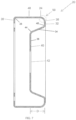
- FIG. 2 illustrates the cross-section of an e embodiment of a wheel 20 according to the present invention illustrating a corner profile 50 in a basic configuration at the first annular edge 24.
- the outer annular face section 32 of the front face surface 28 meets the rim base 48 with a bend that can be about 90 degrees.
- the wheel can have an offset depth D, between the outer annular face section 32 of the front face surface 28 and the hub section 38, as described above, in this example, the back flange 30 is extended with a locking feature or mechanism 31 that can be based on customer specific requirements.
- the embodiment therein can further vary in relation to the embodiment of FIG. 1 B in regards to the angle B between the center hub section 38 and transition section 34 and also angle C between transition section 34 and outer annular face section 32.
- angle B is greater that of the embodiment of FIG. 1 B
- angle C is less than that of the embodiment of RG. 1 B.
- angle B and angle C can range as described above.
- HGs. 3A and 3B illustrate an example of a wheel 20 formed with a hub aperture 42 in center hub section 36.
- the wheel 20 continues along center hub section 36 outward from the hub aperture 42 to the center hub perimeter 44 and continues through a transition section 34 at an angle B about the center hub perimeter 44 ranging from about 20 degrees to about 65 degrees, and any range there between, to the interior edge 48 of the outer annular face section 32.
- Outer annular face section 32 extends from interior edge 46 to a corner profile 50 from which rim base 48 extends.
- the interior edge 46 is spaced inwardly from the wheel rim base 48 of the rim 22 of the wheel 20.
- the outer annular face section 32, the transition section 34 and the center hub section 36 can each be substantially planar in cross-section, as shown for example in FIG. 3B .
- the planar cross-section of the outer annular face section 32 can be substantially parallel to the planar cross-section of center hub section 36.
- the cross-section of the center hub section 36 can be offset inwardly from the cross-section of the annular face section 32 at an off-set D as described above.
- a concave step can be formed in the corner profile 50 before turning from the outer annular face section 32 to the rim base 48.
- the annular corner profile 50 can include a step 54 and have a shoulder 52. in various aspects, shoulder 52 can be spaced about 1 to 2 inches from and generally parallel to the rim base 48 of wheel rim 22.
- the step 54 can turn 90 degrees from shoulder 52 to form a step ring generally parallel to the face of the wheel 20, before turning 90 degrees to the rim base 48.
- the rim base 48 can extend about 2 to 8 inches away from the front face surface back toward the vehicle.
- a back flange 30 can extend from rim base 48 and be formed with a bend of about 60 to 100 degrees radially inward toward the hub aperture 42 of the wheel 20.
- the transition angles are distinct, in other embodiments, the transitions have a radius of curvature.
- FIGs 4A and 4B Illustrated in FIGs 4A and 4B is a non-limiting example of a complete wheel assembly according to various aspects of the present invention comprising the wheel 20, a fire 56, and locking hub attachment 58.
- the tire 56 is configured to mate with the annular corner profile 50 of FIGs, 3A and 3B .
- the wheel 20 can be attached to the hub of the axle of a vehicle at a hub aperture 42.
- the wheel 20 can be secured to the vehicle using a locking hub attachment 58, which can use a plurality of screws 60 to secure the locking hub attachment 56 in place.
- FIGs. 4A and 4B depicts the embodiment of the wheel 20 of FIGs. 3A and 3B .
- FIGs. 1A and 1 B and FIG. 2 can also be used for the assembly along with a tire configured to mate with the surface of the rim 22.
- FIG. 5 illustrates another example of a corner profile 50 of a step configuration for the present wheel 20 having a more rounded transition than that depicted in FIG. 3B .
- This embodiment also illustrates a bolt aperture 40 which is flush to the surface and an extended back flange 30 as compared to the embodiments above.
- FIGs. 6 and 7 similarly depict additional examples of corner profiles 50 with a beveled angle configuration and large radius configuration, respectively.
- a tire 56 can be bonded or secured to any of the embodiments shown in FIGs. 5-7 .
- a tire 56 can be bonded or secured to the substantially flat rim base 48 and the annular corner profile 50, in a manner similar to that shown in the example of FIGs, 4A and 4B .
- the curb test was conducted by driving a scissor lift vehicle into a curb at least 3 inches tall at approximately a 45° angle.
- the vehicle was provided with a wheel as depicted in FIGs. 1A and 1 B .
- the wheel successfully absorbed the shock of being driven into the curb, flexing to absorb the impact, and subsequently returning to its original configuration.
- a drop test was also conducted.
- the drop test involved dropping an entire scissor lift vehicle from a height of approximately 12 inches above the ground onto ail of its wheels and also again onto initially two of its wheels.
- ail four of the wheels of the scissor lift vehicle were of the embodiment of RGs. 1A and 1 B.
- the wheels successfully flexed to absorb the impact, returning to their original shape.
Landscapes
- Engineering & Computer Science (AREA)
- Mechanical Engineering (AREA)
- Chemical & Material Sciences (AREA)
- Combustion & Propulsion (AREA)
- Transportation (AREA)
- Tires In General (AREA)
Claims (13)
- Rad (20) für ein Industriefahrzeug, das umfasst:eine im Wesentlichen zylindrische Radfelge (22), die gegenüberliegende erste (24) und zweite (26) ringförmige Kanten und ein dazwischen befindliches Felgenbett (48) einschließt;eine Nabenöffnung (42), die eine Längsachse (43) aufweist, die durch die Nabenöffnung (42) verläuft, wobei die Längsachse parallel zu der Längsachse einer Achse ist, wobei das Rad konfiguriert ist, an dieselbe montiert zu werden;eine Oberfläche, die sich im montierten Zustand von der Nabenöffnung (42) radial nach außen bis zu der ersten ringförmigen Kante (24) der Radfelge (22) erstreckt; undeinen im Querschnitt im Wesentlichen ebenen hinteren Flansch (30), der sich von der zweiten ringförmigen Kante (26) der Radfelge (22) radial nach innen in Richtung der Längsachse (43) erstreckt, wobei der hintere Flansch (30) in einem Winkel in Bezug auf das Felgenbett (48) geformt ist und ein freies, nach innen gerichtetes distales Ende aufweist, das sich in Richtung der Längsachse (43) erstreckt,wobei die Oberfläche einen zentralen Nabenabschnitt (36), der sich von der Nabenöffnung (42) radial nach außen erstreckt, einen Übergangsabschnitt (34), der sich von dem zentralen Nabenabschnitt (36) radial nach außen erstreckt, und einen äußeren ringförmigen Flächenabschnitt (32) umfasst, der sich von dem Übergangsabschnitt (34) radial nach außen zu der ersten ringförmigen Kante (24) der Radfelge (22) erstreckt, wobei der äußere ringförmige Flächenabschnitt (32) außen entlang der Längsachse (43) in Richtung der ersten ringförmigen Kante (24) von dem zentralen Nabenabschnitt (36) positioniert ist und wobei der äußere ringförmige Flächenabschnitt (32) im Querschnitt im Wesentlichen eben ist und das Felgenbett (48) sich von dem äußeren ringförmigen Flächenabschnitt (32) in einem Winkel (E) von 90 Grad plus oder minus 10 Grad in Bezug auf den im Wesentlichen ebenen äußeren ringförmigen Flächenabschnitt (32) fortsetzt,dadurch gekennzeichnet, dassder zentrale Nabenabschnitt (36) einen im Wesentlichen ebenen Querschnitt aufweist, wobei der im Wesentlichen ebene Querschnitt des zentralen Nabenabschnitts (36) und der im Wesentlichen ebene Querschnitt des äußeren ringförmigen Flächenabschnitts (32) im Wesentlichen parallel zueinander sind und alternativ:- der zentrale Nabenabschnitt (36) einen im Wesentlichen ebenen Querschnitt aufweist, der auf einer Mittellinie (37) liegt, die vertikal durch einen Querschnitt des Rades gezogen ist, wobei die Mittellinie (37) in gleichem Abstand zwischen der ersten (24) und zweiten (26) ringförmigen Kante gezogen ist;
oder- wobei der zentrale Nabenabschnitt (36) entweder nach außen entlang der Längsachse (43) in Richtung des äußeren ringförmigen Flächenabschnitts (32) oder nach innen entlang der Längsachse (43) in Richtung des hinteren Flansches (30) von einer Mittellinie (37) versetzt ist, die vertikal durch einen Querschnitt des Rades (20) gezogen ist, wobei die Mittellinie (37) in gleichem Abstand zwischen der ersten (24) und zweiten (26) ringförmigen Kante gezogen ist. - Rad nach Anspruch 1, wobei der Versatz des zentralen Nabenabschnitts (36) 30 % des Abstands zwischen der Mittellinie (37) und entweder dem äußeren ringförmigen Flächenabschnitt (32) oder dem hinteren Flansch (30) oder weniger beträgt.
- Rad nach Anspruch 1, wobei der im Wesentlichen ebene Querschnitt des äußeren ringförmigen Flächenabschnitts (32) oder der im Wesentlichen ebene Querschnitt des zentralen Nabenabschnitts (36) oder beide im Wesentlichen senkrecht zu dem im Wesentlichen ebenen Querschnitt des Felgenbetts (48) sind.
- Rad nach einem der Ansprüche 1 bis 3, wobei der Übergangsabschnitt (34) einen im Wesentlichen ebenen Querschnitt aufweist.
- Rad nach einem der Ansprüche 1 bis 4, wobei sich der Übergangsabschnitt (34) von dem zentralen Nabenabschnitt (36) in einem Winkel (B) nach außen erstreckt und der Winkel (B) in dem Bereich von 15 bis 60 Grad in Bezug auf eine Mittellinie (37) liegt, die vertikal durch einen Querschnitt des Rades gezogen ist, wobei die Mittellinie (37) in gleichem Abstand zwischen der ersten (24) und zweiten (26) ringförmigen Kante gezogen ist.
- Rad nach einem der Ansprüche 1 bis 5, wobei sich der äußere ringförmige Flächenabschnitt (32) von dem Übergangsabschnitt (34) in einem Winkel (C) nach außen erstreckt und der Winkel (C) in dem Bereich von 120 Grad bis 165 Grad in Bezug auf eine ebene Fläche des äußeren ringförmigen Flächenabschnitts (32) parallel zu einer Mittellinie liegt, die vertikal durch einen Querschnitt des Rades gezogen ist, wobei die Mittellinie (37) in gleichem Abstand zwischen der ersten (24) und zweiten (26) ringförmigen Kante gezogen ist.
- Rad nach einem der Ansprüche 1 bis 6, wobei sich der zentrale Nabenabschnitt (36) von der Nabenöffnung (42) in einem Winkel (A) von im Wesentlichen 90° in Bezug auf die Längsachse (43) radial nach außen erstreckt.
- Rad nach einem der Ansprüche 1 bis 7, das ferner eine konkave Stufe (54), einen konvexen Radiusabschnitt (50, Fig. 5) oder einen abgewinkelten Abschnitt (50, Fig. 6) zwischen der äußeren ringförmigen Fläche (32) und der Radfelge (22) umfasst.
- Rad nach einem der Ansprüche 1 bis 8, wobei die Radfelge (22) ausgestaltet ist, um einen Reifen (56) aufzunehmen und an seinem Platz zu sichern.
- Rad nach einem der Ansprüche 1 bis 9, wobei der Winkel zwischen der Radfelge (22) und dem hinteren Flansch (30) ein Winkel (F) in dem Bereich zwischen 45 Grad und 135 Grad in Bezug auf eine zwischen der ersten ringförmigen Kante (24) und der zweiten ringförmigen Kante (26) des Felgenbetts (22) gezogene ebene Linie ist.
- Rad nach einem der Ansprüche 1 bis 10, wobei der hintere Flansch (30) eine Länge aufweist, die mindestens doppelt so groß wie die Dicke des Flansches ist.
- Rad nach einem der Ansprüche 1 bis 11, wobei das Industriefahrzeug ausgewählt ist aus der Gruppe, bestehend aus einem Scherenhubfahrzeug, einem Fahrzeug mit Hubarbeitsbühne, einem Gabelstaplerfahrzeug und einem Ground-Support-Equipment-Fahrzeug.
- Rad nach einem der Ansprüche 1 bis 12, wobei das Rad eine einteilige Konstruktion aus einem Metallstück, vorzugsweise Stahl, ist, das vorzugsweise eine Dicke von 2 mm bis 5 mm aufweist.
Applications Claiming Priority (2)
| Application Number | Priority Date | Filing Date | Title |
|---|---|---|---|
| US201662357712P | 2016-07-01 | 2016-07-01 | |
| PCT/US2017/039903 WO2018005741A1 (en) | 2016-07-01 | 2017-06-29 | Wheel for industrial vehicle |
Publications (3)
| Publication Number | Publication Date |
|---|---|
| EP3481645A1 EP3481645A1 (de) | 2019-05-15 |
| EP3481645A4 EP3481645A4 (de) | 2020-02-26 |
| EP3481645B1 true EP3481645B1 (de) | 2024-11-13 |
Family
ID=60787586
Family Applications (1)
| Application Number | Title | Priority Date | Filing Date |
|---|---|---|---|
| EP17821219.7A Active EP3481645B1 (de) | 2016-07-01 | 2017-06-29 | Rad für industriefahrzeug |
Country Status (4)
| Country | Link |
|---|---|
| US (1) | US10787030B2 (de) |
| EP (1) | EP3481645B1 (de) |
| CN (1) | CN110072706A (de) |
| WO (1) | WO2018005741A1 (de) |
Families Citing this family (1)
| Publication number | Priority date | Publication date | Assignee | Title |
|---|---|---|---|---|
| US11850885B2 (en) * | 2016-07-01 | 2023-12-26 | Fredrick Taylor | Wheel for industrial vehicle |
Citations (1)
| Publication number | Priority date | Publication date | Assignee | Title |
|---|---|---|---|---|
| WO2015150333A2 (en) * | 2014-04-01 | 2015-10-08 | Hutchinson Sa | Road wheel |
Family Cites Families (22)
| Publication number | Priority date | Publication date | Assignee | Title |
|---|---|---|---|---|
| FR1578979A (de) * | 1968-05-17 | 1969-08-22 | ||
| GB1315160A (en) | 1970-08-19 | 1973-04-26 | Raleigh Industries Ltd | Vehicle wheel |
| US3894776A (en) * | 1973-04-16 | 1975-07-15 | Pemco Kalamazoo | Wheel construction |
| US4350196A (en) | 1976-09-13 | 1982-09-21 | The Goodyear Tire & Rubber Company | Non-pneumatic structurally resilient integrated wheel-tire |
| US4253510A (en) * | 1979-10-22 | 1981-03-03 | Lorean John Z De | Integral wheel and pneumatic tire |
| US4950030A (en) * | 1986-05-30 | 1990-08-21 | Motor Wheel Corporation | Wheel for a track laying vehicle |
| JPH01162802U (de) * | 1989-04-13 | 1989-11-13 | ||
| US4923257A (en) * | 1989-04-13 | 1990-05-08 | Caterpillar Inc. | Belted vehicle suspension system |
| US5312176A (en) * | 1992-09-25 | 1994-05-17 | Catepillar Inc. | Self-aligning idler wheel assembly |
| US5293948A (en) | 1992-09-25 | 1994-03-15 | Caterpillar Inc. | Undercarriage assembly for a vehicle |
| IT1256740B (it) * | 1992-12-18 | 1995-12-15 | Claber Spa | Procedimento per la fabbricazione di una ruota gommata in materiale sintetico, particolarmente per carrello avvolgitubo per giardinaggio eruota cosi' ottenuta |
| DE9411258U1 (de) | 1994-07-12 | 1994-09-08 | Bruder Spielwaren GmbH & Co. KG, 90768 Fürth | Rad für Spielzeugfahrzeuge |
| WO1998023455A1 (en) | 1996-11-26 | 1998-06-04 | Hayes Wheels International, Inc. | Universal vehicle wheel |
| JPH1142901A (ja) | 1997-07-25 | 1999-02-16 | Topy Ind Ltd | 2ピースフルデザインホイール |
| JPH11151901A (ja) | 1997-11-20 | 1999-06-08 | Topy Ind Ltd | 2ピースフルデザインホイール |
| DE19807943C2 (de) | 1998-02-25 | 2002-12-12 | Porsche Ag | Rad für ein Fahrzeug, insbesondere Ersatzrad für ein Kraftfahrzeug |
| WO2003031206A1 (en) * | 2001-10-02 | 2003-04-17 | Bridgestone Corporation | Assembly of tire and rim, and tire |
| CN201729027U (zh) * | 2009-08-20 | 2011-02-02 | 潘坚敏 | 安全型轮毂 |
| JP5592945B2 (ja) | 2010-05-21 | 2014-09-17 | 中央精機株式会社 | 自動車用ホイール |
| US8967737B2 (en) | 2010-06-30 | 2015-03-03 | Camoplast Solideal Inc. | Wheel of a track assembly of a tracked vehicle |
| FR2993501B1 (fr) * | 2012-07-20 | 2014-08-08 | Michelin & Cie | Pneumatique optimise. |
| CN105270087A (zh) * | 2014-06-12 | 2016-01-27 | 宁波市鄞州雄达车辆配件厂 | 一种两片式车轮 |
-
2017
- 2017-06-29 EP EP17821219.7A patent/EP3481645B1/de active Active
- 2017-06-29 CN CN201780041285.5A patent/CN110072706A/zh active Pending
- 2017-06-29 US US15/637,137 patent/US10787030B2/en active Active
- 2017-06-29 WO PCT/US2017/039903 patent/WO2018005741A1/en not_active Ceased
Patent Citations (1)
| Publication number | Priority date | Publication date | Assignee | Title |
|---|---|---|---|---|
| WO2015150333A2 (en) * | 2014-04-01 | 2015-10-08 | Hutchinson Sa | Road wheel |
Also Published As
| Publication number | Publication date |
|---|---|
| US10787030B2 (en) | 2020-09-29 |
| US20180001700A1 (en) | 2018-01-04 |
| EP3481645A1 (de) | 2019-05-15 |
| WO2018005741A1 (en) | 2018-01-04 |
| EP3481645A4 (de) | 2020-02-26 |
| CN110072706A (zh) | 2019-07-30 |
Similar Documents
| Publication | Publication Date | Title |
|---|---|---|
| US9242506B2 (en) | Modular center cap assembly for wheels | |
| US7523773B2 (en) | Non-pneumatic wheel | |
| US10093361B2 (en) | Adjustable vehicular fender extension | |
| US9873303B2 (en) | Damper having reinforced catcher | |
| JP6577825B2 (ja) | エアレスタイヤ、及び、エアレスタイヤ用のハブ部 | |
| US20160052389A1 (en) | Steerable wheel side of a drive axle | |
| CN106183623B (zh) | 轮毂安装段之螺栓孔间含有凹孔的汽车轮圈 | |
| CN109789724A (zh) | 用于具有浮动座的车辆车轮的柔性轮毂盖及具有浮动座和柔性轮毂盖的车轮 | |
| EP3481645B1 (de) | Rad für industriefahrzeug | |
| EA031439B1 (ru) | Колесо транспортного средства для пассажирских автомобилей | |
| WO2018106491A3 (en) | Hub for heavy-duty vehicle | |
| US11850885B2 (en) | Wheel for industrial vehicle | |
| KR20200069605A (ko) | 실린더 타이어 | |
| US20190135030A1 (en) | Expandable and retractable wheel assembly | |
| US11697304B2 (en) | Vehicle wheel disc and vehicle disc wheel | |
| EP1680286B1 (de) | Anordnung und verfahren zur montage einer radkappe an einem fahrzeug | |
| CN104379360A (zh) | 车辆轮辋 | |
| CN104669937A (zh) | 车轴和车轴组件 | |
| EP2631086B1 (de) | Fahrzeugradmontageanordnung und zugehörige Radnabenanordnung | |
| CN110588238B (zh) | 车轮 | |
| RU2572486C1 (ru) | Трехкольцевая колесная вставка безопасности | |
| CN211710538U (zh) | 一种大型复合型车轮 | |
| CN204820941U (zh) | 汽车车轮 | |
| CN104066594B (zh) | 用于废物收集箱的轮胎和轮子 | |
| US20240066927A1 (en) | Luminescent non-pneumatic tire device |
Legal Events
| Date | Code | Title | Description |
|---|---|---|---|
| STAA | Information on the status of an ep patent application or granted ep patent |
Free format text: STATUS: THE INTERNATIONAL PUBLICATION HAS BEEN MADE |
|
| PUAI | Public reference made under article 153(3) epc to a published international application that has entered the european phase |
Free format text: ORIGINAL CODE: 0009012 |
|
| STAA | Information on the status of an ep patent application or granted ep patent |
Free format text: STATUS: REQUEST FOR EXAMINATION WAS MADE |
|
| 17P | Request for examination filed |
Effective date: 20190122 |
|
| AK | Designated contracting states |
Kind code of ref document: A1 Designated state(s): AL AT BE BG CH CY CZ DE DK EE ES FI FR GB GR HR HU IE IS IT LI LT LU LV MC MK MT NL NO PL PT RO RS SE SI SK SM TR |
|
| AX | Request for extension of the european patent |
Extension state: BA ME |
|
| DAV | Request for validation of the european patent (deleted) | ||
| DAX | Request for extension of the european patent (deleted) | ||
| A4 | Supplementary search report drawn up and despatched |
Effective date: 20200127 |
|
| RIC1 | Information provided on ipc code assigned before grant |
Ipc: B60B 21/02 20060101ALI20200121BHEP Ipc: B60B 9/00 20060101ALI20200121BHEP Ipc: B60C 15/02 20060101ALI20200121BHEP Ipc: B60B 3/00 20060101ALI20200121BHEP Ipc: B60B 3/02 20060101ALI20200121BHEP Ipc: B60B 21/04 20060101ALI20200121BHEP Ipc: B60C 3/02 20060101ALI20200121BHEP Ipc: B60C 3/00 20060101ALI20200121BHEP Ipc: B60B 19/00 20060101AFI20200121BHEP Ipc: B60C 15/00 20060101ALI20200121BHEP Ipc: B60B 7/02 20060101ALI20200121BHEP |
|
| STAA | Information on the status of an ep patent application or granted ep patent |
Free format text: STATUS: EXAMINATION IS IN PROGRESS |
|
| 17Q | First examination report despatched |
Effective date: 20220721 |
|
| GRAP | Despatch of communication of intention to grant a patent |
Free format text: ORIGINAL CODE: EPIDOSNIGR1 |
|
| STAA | Information on the status of an ep patent application or granted ep patent |
Free format text: STATUS: GRANT OF PATENT IS INTENDED |
|
| INTG | Intention to grant announced |
Effective date: 20240607 |
|
| GRAS | Grant fee paid |
Free format text: ORIGINAL CODE: EPIDOSNIGR3 |
|
| GRAA | (expected) grant |
Free format text: ORIGINAL CODE: 0009210 |
|
| STAA | Information on the status of an ep patent application or granted ep patent |
Free format text: STATUS: THE PATENT HAS BEEN GRANTED |
|
| AK | Designated contracting states |
Kind code of ref document: B1 Designated state(s): AL AT BE BG CH CY CZ DE DK EE ES FI FR GB GR HR HU IE IS IT LI LT LU LV MC MK MT NL NO PL PT RO RS SE SI SK SM TR |
|
| REG | Reference to a national code |
Ref country code: GB Ref legal event code: FG4D |
|
| REG | Reference to a national code |
Ref country code: CH Ref legal event code: EP |
|
| REG | Reference to a national code |
Ref country code: IE Ref legal event code: FG4D |
|
| REG | Reference to a national code |
Ref country code: DE Ref legal event code: R096 Ref document number: 602017086130 Country of ref document: DE |
|
| REG | Reference to a national code |
Ref country code: LT Ref legal event code: MG9D |
|
| REG | Reference to a national code |
Ref country code: NL Ref legal event code: MP Effective date: 20241113 |
|
| P01 | Opt-out of the competence of the unified patent court (upc) registered |
Free format text: CASE NUMBER: APP_8288/2025 Effective date: 20250218 |
|
| PG25 | Lapsed in a contracting state [announced via postgrant information from national office to epo] |
Ref country code: PT Free format text: LAPSE BECAUSE OF FAILURE TO SUBMIT A TRANSLATION OF THE DESCRIPTION OR TO PAY THE FEE WITHIN THE PRESCRIBED TIME-LIMIT Effective date: 20250313 Ref country code: HR Free format text: LAPSE BECAUSE OF FAILURE TO SUBMIT A TRANSLATION OF THE DESCRIPTION OR TO PAY THE FEE WITHIN THE PRESCRIBED TIME-LIMIT Effective date: 20241113 Ref country code: IS Free format text: LAPSE BECAUSE OF FAILURE TO SUBMIT A TRANSLATION OF THE DESCRIPTION OR TO PAY THE FEE WITHIN THE PRESCRIBED TIME-LIMIT Effective date: 20250313 |
|
| PG25 | Lapsed in a contracting state [announced via postgrant information from national office to epo] |
Ref country code: FI Free format text: LAPSE BECAUSE OF FAILURE TO SUBMIT A TRANSLATION OF THE DESCRIPTION OR TO PAY THE FEE WITHIN THE PRESCRIBED TIME-LIMIT Effective date: 20241113 Ref country code: NL Free format text: LAPSE BECAUSE OF FAILURE TO SUBMIT A TRANSLATION OF THE DESCRIPTION OR TO PAY THE FEE WITHIN THE PRESCRIBED TIME-LIMIT Effective date: 20241113 |
|
| REG | Reference to a national code |
Ref country code: AT Ref legal event code: MK05 Ref document number: 1741420 Country of ref document: AT Kind code of ref document: T Effective date: 20241113 |
|
| PG25 | Lapsed in a contracting state [announced via postgrant information from national office to epo] |
Ref country code: BG Free format text: LAPSE BECAUSE OF FAILURE TO SUBMIT A TRANSLATION OF THE DESCRIPTION OR TO PAY THE FEE WITHIN THE PRESCRIBED TIME-LIMIT Effective date: 20241113 |
|
| PG25 | Lapsed in a contracting state [announced via postgrant information from national office to epo] |
Ref country code: ES Free format text: LAPSE BECAUSE OF FAILURE TO SUBMIT A TRANSLATION OF THE DESCRIPTION OR TO PAY THE FEE WITHIN THE PRESCRIBED TIME-LIMIT Effective date: 20241113 |
|
| PG25 | Lapsed in a contracting state [announced via postgrant information from national office to epo] |
Ref country code: NO Free format text: LAPSE BECAUSE OF FAILURE TO SUBMIT A TRANSLATION OF THE DESCRIPTION OR TO PAY THE FEE WITHIN THE PRESCRIBED TIME-LIMIT Effective date: 20250213 |
|
| PG25 | Lapsed in a contracting state [announced via postgrant information from national office to epo] |
Ref country code: GR Free format text: LAPSE BECAUSE OF FAILURE TO SUBMIT A TRANSLATION OF THE DESCRIPTION OR TO PAY THE FEE WITHIN THE PRESCRIBED TIME-LIMIT Effective date: 20250214 Ref country code: LV Free format text: LAPSE BECAUSE OF FAILURE TO SUBMIT A TRANSLATION OF THE DESCRIPTION OR TO PAY THE FEE WITHIN THE PRESCRIBED TIME-LIMIT Effective date: 20241113 Ref country code: AT Free format text: LAPSE BECAUSE OF FAILURE TO SUBMIT A TRANSLATION OF THE DESCRIPTION OR TO PAY THE FEE WITHIN THE PRESCRIBED TIME-LIMIT Effective date: 20241113 |
|
| PG25 | Lapsed in a contracting state [announced via postgrant information from national office to epo] |
Ref country code: PL Free format text: LAPSE BECAUSE OF FAILURE TO SUBMIT A TRANSLATION OF THE DESCRIPTION OR TO PAY THE FEE WITHIN THE PRESCRIBED TIME-LIMIT Effective date: 20241113 |
|
| PG25 | Lapsed in a contracting state [announced via postgrant information from national office to epo] |
Ref country code: RS Free format text: LAPSE BECAUSE OF FAILURE TO SUBMIT A TRANSLATION OF THE DESCRIPTION OR TO PAY THE FEE WITHIN THE PRESCRIBED TIME-LIMIT Effective date: 20250213 |
|
| REG | Reference to a national code |
Ref country code: DE Ref legal event code: R081 Ref document number: 602017086130 Country of ref document: DE Owner name: TAYLOR WHEEL AUTOMATION LLC, ROME, US Free format text: FORMER OWNER: TAYLOR, FREDRICK, ROME, GA, US |
|
| REG | Reference to a national code |
Ref country code: CH Ref legal event code: PK Free format text: BERICHTIGUNGEN |
|
| RAP2 | Party data changed (patent owner data changed or rights of a patent transferred) |
Owner name: TAYLOR WHEEL AUTOMATION LLC |
|
| RIN2 | Information on inventor provided after grant (corrected) |
Inventor name: TAYLOR, FREDERICK |
|
| PG25 | Lapsed in a contracting state [announced via postgrant information from national office to epo] |
Ref country code: SM Free format text: LAPSE BECAUSE OF FAILURE TO SUBMIT A TRANSLATION OF THE DESCRIPTION OR TO PAY THE FEE WITHIN THE PRESCRIBED TIME-LIMIT Effective date: 20241113 |
|
| PGFP | Annual fee paid to national office [announced via postgrant information from national office to epo] |
Ref country code: DE Payment date: 20250627 Year of fee payment: 9 |
|
| PG25 | Lapsed in a contracting state [announced via postgrant information from national office to epo] |
Ref country code: DK Free format text: LAPSE BECAUSE OF FAILURE TO SUBMIT A TRANSLATION OF THE DESCRIPTION OR TO PAY THE FEE WITHIN THE PRESCRIBED TIME-LIMIT Effective date: 20241113 |
|
| PGFP | Annual fee paid to national office [announced via postgrant information from national office to epo] |
Ref country code: GB Payment date: 20250627 Year of fee payment: 9 |
|
| PGFP | Annual fee paid to national office [announced via postgrant information from national office to epo] |
Ref country code: BE Payment date: 20250627 Year of fee payment: 9 |
|
| PG25 | Lapsed in a contracting state [announced via postgrant information from national office to epo] |
Ref country code: EE Free format text: LAPSE BECAUSE OF FAILURE TO SUBMIT A TRANSLATION OF THE DESCRIPTION OR TO PAY THE FEE WITHIN THE PRESCRIBED TIME-LIMIT Effective date: 20241113 |
|
| PGFP | Annual fee paid to national office [announced via postgrant information from national office to epo] |
Ref country code: FR Payment date: 20250625 Year of fee payment: 9 |
|
| PG25 | Lapsed in a contracting state [announced via postgrant information from national office to epo] |
Ref country code: RO Free format text: LAPSE BECAUSE OF FAILURE TO SUBMIT A TRANSLATION OF THE DESCRIPTION OR TO PAY THE FEE WITHIN THE PRESCRIBED TIME-LIMIT Effective date: 20241113 |
|
| PG25 | Lapsed in a contracting state [announced via postgrant information from national office to epo] |
Ref country code: SK Free format text: LAPSE BECAUSE OF FAILURE TO SUBMIT A TRANSLATION OF THE DESCRIPTION OR TO PAY THE FEE WITHIN THE PRESCRIBED TIME-LIMIT Effective date: 20241113 |
|
| PG25 | Lapsed in a contracting state [announced via postgrant information from national office to epo] |
Ref country code: CZ Free format text: LAPSE BECAUSE OF FAILURE TO SUBMIT A TRANSLATION OF THE DESCRIPTION OR TO PAY THE FEE WITHIN THE PRESCRIBED TIME-LIMIT Effective date: 20241113 |
|
| PG25 | Lapsed in a contracting state [announced via postgrant information from national office to epo] |
Ref country code: IT Free format text: LAPSE BECAUSE OF FAILURE TO SUBMIT A TRANSLATION OF THE DESCRIPTION OR TO PAY THE FEE WITHIN THE PRESCRIBED TIME-LIMIT Effective date: 20241113 |
|
| REG | Reference to a national code |
Ref country code: DE Ref legal event code: R097 Ref document number: 602017086130 Country of ref document: DE |
|
| REG | Reference to a national code |
Ref country code: BE Ref legal event code: PD Owner name: TAYLOR WHEEL AUTOMATION LLC; US Free format text: DETAILS ASSIGNMENT: CHANGE OF OWNER(S), ASSIGNMENT; FORMER OWNER NAME: TAYLOR, FREDRICK Effective date: 20250612 |
|
| PG25 | Lapsed in a contracting state [announced via postgrant information from national office to epo] |
Ref country code: SE Free format text: LAPSE BECAUSE OF FAILURE TO SUBMIT A TRANSLATION OF THE DESCRIPTION OR TO PAY THE FEE WITHIN THE PRESCRIBED TIME-LIMIT Effective date: 20241113 |
|
| PLBE | No opposition filed within time limit |
Free format text: ORIGINAL CODE: 0009261 |
|
| STAA | Information on the status of an ep patent application or granted ep patent |
Free format text: STATUS: NO OPPOSITION FILED WITHIN TIME LIMIT |
|
| 26N | No opposition filed |
Effective date: 20250814 |
|
| REG | Reference to a national code |
Ref country code: CH Ref legal event code: H13 Free format text: ST27 STATUS EVENT CODE: U-0-0-H10-H13 (AS PROVIDED BY THE NATIONAL OFFICE) Effective date: 20260127 |
|
| PG25 | Lapsed in a contracting state [announced via postgrant information from national office to epo] |
Ref country code: MC Free format text: LAPSE BECAUSE OF FAILURE TO SUBMIT A TRANSLATION OF THE DESCRIPTION OR TO PAY THE FEE WITHIN THE PRESCRIBED TIME-LIMIT Effective date: 20241113 |
|
| PG25 | Lapsed in a contracting state [announced via postgrant information from national office to epo] |
Ref country code: LU Free format text: LAPSE BECAUSE OF NON-PAYMENT OF DUE FEES Effective date: 20250629 |
|
| PG25 | Lapsed in a contracting state [announced via postgrant information from national office to epo] |
Ref country code: IE Free format text: LAPSE BECAUSE OF NON-PAYMENT OF DUE FEES Effective date: 20250629 |
|
| PG25 | Lapsed in a contracting state [announced via postgrant information from national office to epo] |
Ref country code: CH Free format text: LAPSE BECAUSE OF NON-PAYMENT OF DUE FEES Effective date: 20250630 |