EP3481329B1 - System zur reinigung und desinfektion von zahnfleischoberflächen um zahnprothesen-tragende implantatstrukturen herum - Google Patents
System zur reinigung und desinfektion von zahnfleischoberflächen um zahnprothesen-tragende implantatstrukturen herum Download PDFInfo
- Publication number
- EP3481329B1 EP3481329B1 EP17823756.6A EP17823756A EP3481329B1 EP 3481329 B1 EP3481329 B1 EP 3481329B1 EP 17823756 A EP17823756 A EP 17823756A EP 3481329 B1 EP3481329 B1 EP 3481329B1
- Authority
- EP
- European Patent Office
- Prior art keywords
- denture
- component
- liquid
- plate
- conduit
- Prior art date
- Legal status (The legal status is an assumption and is not a legal conclusion. Google has not performed a legal analysis and makes no representation as to the accuracy of the status listed.)
- Active
Links
- 230000000249 desinfective effect Effects 0.000 title claims description 33
- 239000007943 implant Substances 0.000 title claims description 33
- 238000004140 cleaning Methods 0.000 title claims description 31
- 239000007788 liquid Substances 0.000 claims description 86
- 239000004053 dental implant Substances 0.000 claims description 25
- 230000003094 perturbing effect Effects 0.000 claims description 4
- XLYOFNOQVPJJNP-UHFFFAOYSA-N water Substances O XLYOFNOQVPJJNP-UHFFFAOYSA-N 0.000 description 8
- 244000005700 microbiome Species 0.000 description 7
- 230000000694 effects Effects 0.000 description 5
- 239000000463 material Substances 0.000 description 5
- 238000012423 maintenance Methods 0.000 description 4
- 239000000243 solution Substances 0.000 description 4
- 208000015181 infectious disease Diseases 0.000 description 3
- 238000004519 manufacturing process Methods 0.000 description 3
- 238000000034 method Methods 0.000 description 3
- 206010006326 Breath odour Diseases 0.000 description 2
- 238000005266 casting Methods 0.000 description 2
- 230000000295 complement effect Effects 0.000 description 2
- 238000007599 discharging Methods 0.000 description 2
- 238000005553 drilling Methods 0.000 description 2
- 239000003814 drug Substances 0.000 description 2
- 206010013781 dry mouth Diseases 0.000 description 2
- 238000005530 etching Methods 0.000 description 2
- 239000002324 mouth wash Substances 0.000 description 2
- 229940051866 mouthwash Drugs 0.000 description 2
- 239000002245 particle Substances 0.000 description 2
- 238000011282 treatment Methods 0.000 description 2
- 238000010146 3D printing Methods 0.000 description 1
- 208000005946 Xerostomia Diseases 0.000 description 1
- 210000000988 bone and bone Anatomy 0.000 description 1
- 230000001680 brushing effect Effects 0.000 description 1
- 238000010276 construction Methods 0.000 description 1
- 230000001419 dependent effect Effects 0.000 description 1
- 229940079593 drug Drugs 0.000 description 1
- 239000001963 growth medium Substances 0.000 description 1
- 238000002347 injection Methods 0.000 description 1
- 239000007924 injection Substances 0.000 description 1
- 230000002906 microbiologic effect Effects 0.000 description 1
- 239000003960 organic solvent Substances 0.000 description 1
- 230000004962 physiological condition Effects 0.000 description 1
- 210000004872 soft tissue Anatomy 0.000 description 1
- 238000005507 spraying Methods 0.000 description 1
- 238000004659 sterilization and disinfection Methods 0.000 description 1
- 238000001356 surgical procedure Methods 0.000 description 1
- 208000011580 syndromic disease Diseases 0.000 description 1
- 238000005406 washing Methods 0.000 description 1
Images


Classifications
-
- A—HUMAN NECESSITIES
- A61—MEDICAL OR VETERINARY SCIENCE; HYGIENE
- A61C—DENTISTRY; APPARATUS OR METHODS FOR ORAL OR DENTAL HYGIENE
- A61C8/00—Means to be fixed to the jaw-bone for consolidating natural teeth or for fixing dental prostheses thereon; Dental implants; Implanting tools
-
- A—HUMAN NECESSITIES
- A61—MEDICAL OR VETERINARY SCIENCE; HYGIENE
- A61C—DENTISTRY; APPARATUS OR METHODS FOR ORAL OR DENTAL HYGIENE
- A61C13/00—Dental prostheses; Making same
- A61C13/01—Palates or other bases or supports for the artificial teeth; Making same
-
- A—HUMAN NECESSITIES
- A61—MEDICAL OR VETERINARY SCIENCE; HYGIENE
- A61C—DENTISTRY; APPARATUS OR METHODS FOR ORAL OR DENTAL HYGIENE
- A61C17/00—Devices for cleaning, polishing, rinsing or drying teeth, teeth cavities or prostheses; Saliva removers; Dental appliances for receiving spittle
- A61C17/02—Rinsing or air-blowing devices, e.g. using fluid jets or comprising liquid medication
- A61C17/0211—Rinsing or air-blowing devices, e.g. using fluid jets or comprising liquid medication specially adapted for rinsing the teeth of at least one jaw simultaneously
-
- A—HUMAN NECESSITIES
- A61—MEDICAL OR VETERINARY SCIENCE; HYGIENE
- A61C—DENTISTRY; APPARATUS OR METHODS FOR ORAL OR DENTAL HYGIENE
- A61C19/00—Dental auxiliary appliances
- A61C19/06—Implements for therapeutic treatment
- A61C19/063—Medicament applicators for teeth or gums, e.g. treatment with fluorides
-
- A—HUMAN NECESSITIES
- A61—MEDICAL OR VETERINARY SCIENCE; HYGIENE
- A61C—DENTISTRY; APPARATUS OR METHODS FOR ORAL OR DENTAL HYGIENE
- A61C8/00—Means to be fixed to the jaw-bone for consolidating natural teeth or for fixing dental prostheses thereon; Dental implants; Implanting tools
- A61C8/0093—Features of implants not otherwise provided for
- A61C8/0095—Total denture implant
Definitions
- the present invention relates to a system for the cleaning and disinfecting of gum surfaces surrounding implant structures that support dentures.
- Denture an artificial replacement for one or more teeth; especially: a set of false teeth-also referred to as “dental plate” or “denture plate”.
- dentures refers to "removable dentures” that can be readily placed and removed from the mouth of the user and to “fixated dentures” that requires the activities of a dentistry-professional to be placed and remove from the mouth of the user.
- Alveolar relating to, or constituting the part of the jaws where the teeth arise.
- Gum the alveolar portion of a jaw with its enveloping soft tissues.
- Implant "to place (something) in a person's body by means of surgery".
- implant refers to a dental implant that is a surgical component that interfaces with the bone of the alveolar to support a dental prosthesis such as a crown, bridge or denture.
- Dental implants typically connect dentures to the alveolar in a fixated configuration.
- the dentures are positioned in place and removed from the mouth of the patient by a procedure carried out by a dentist or another dentistry-professional.
- the fixated dentures are positioned in contact with the gums of the persons wearing dentures.
- large size dentures typically, supporting more than one tooth
- the contact with the gums is not continuous and homogeneous throughout the surfaces of the dentures facing the gums.
- the physiological conditions encourage the development of microorganisms.
- the development of microorganisms may cause bad-breath and/or infections.
- the caused infections may be severe so as to damage the connection between the implant and the alveolar a well as to cause pain and deteriorate the general health of the person having the implants in his or her mouth.
- "maintenance activities" are required to prevent the development of the microorganisms that thrive on the gums of patients wearing dentures.
- Typical "maintenance activities”, referred to as “mechanical oral hygiene practices”, are usually done by mechanical means such as but not limited to, brushing and/or water squirting and/or disinfecting solution, and are limited in their effectiveness. The limited effectiveness is due to the enclosure of the surfaces to be treated, especially areas in close vicinity to implants, between the gums and the dentures.
- the “maintenance activities” physically remove the microorganisms as well as disinfect the treated areas against remaining and new microorganisms.
- the “maintenance activities” also include the removal of "entrapped" food particles that may serve as growth-media for microorganisms.
- liquid refers to, but not limited to, water.
- the used liquid can also be a water or an organic solvent solution of a disinfection medication or/and an dental-treatment medicinal-drug.
- pressured gas refers to, but not limited to, air and may be any gas(es) used in dental treatments.
- a classical method for the cleaning and disinfecting removable dentures, when worn as well as when not in use and for cleaning and disinfecting fixated dentures is the spraying of a jet of water or a jet of a mouth-wash solution on the surfaces and/or side of the dentures by a device commonly known as a "water flosser".
- a water flosser An example of water flosser devices is shown in the web sites of the Waterpik Company (http://getwaterpik.com/ and https://www.waterpik.com/oral-health/dental-needs/dental-work/implants/).
- Patent document US 2008/272153 A1 discloses a system and a method for delivering a liquid orally to a mouth of a user, to a mouth guard, a night guard a buccual shield, or dentures.
- the device of US 2008/272153 A1 may be helpful in treating xerostomia also known as dry mouth syndrome.
- the present invention is an effective and easy to use, system for the cleaning and disinfecting gum surfaces of fixated dentures, especially of gum surfaces in the close proximity to implants that support the fixated dentures.
- the system of the present invention removes and disinfects against microorganisms as well as washes out "entrapped" food and other particles from surfaces of the gums and especially surfaces immediately surrounding the dental implants supporting the dentures.
- denture-plate In cases where more than a few teeth are missing, typically a relatively large denture is used, referred to in the text that follows as: "denture-plate".
- the denture plate has false teeth on one side and on the opposite side a gum-contacting surface that rests on the gum of the wearer.
- the plate In a fixated-in-place denture plate, the plate is typically connected to the alveolar of the wearer by dental implants.
- the problem underlying the present invention is solved by a system according to present claim 1, advantageous embodiments are disclosed in the dependent claims.
- the preset invention is a system for easy and effective cleaning and disinfecting the gum-denture contact surfaces of a fixated-in-place denture plate, especially for cleaning and disinfecting the surfaces immediately surrounding the implants structures in the gum of the denture wearer that support the denture plate. The longer the time elapse between cleaning episodes of the denture while the denture is in place in the mouth of the wearer, the greater the risk of microbiological infections as well as bad-breath incidences.
- the system for the cleaning and disinfecting of gum surfaces surrounding implants that support dentures of the present invention is composed of: a denture plate having a smooth gum contact surface, at least one Denture-Alveolar-Implant Liquid Dispenser (DAILD) and a conduit liquid streaming system.
- DAILD Denture-Alveolar-Implant Liquid Dispenser
- Each DAILD is constructed of: a dental implant structure, a locking component, a basin-structure and fastening-component.
- the locking component, basin-structure and fastening-component of each DAILD and the conduit liquid streaming system are embedded in pre-defined "dug in” structure in the denture plate and form a smooth surface alignment configuration with the gum contact surface of the denture plate.
- the term "dug in” structure refers to predefined channel (or channels) and cavities that penetrate into the surface of the denture plate (12) and are produced by (and not limited to): etching or/and drilling and/or pre-casting into plate (12).
- the dental implant structure is implanted into the alveolar of the wearer of the denture plate and has a hollow tube structure.
- the locking component is constructed of: a plate with a protruding bar that connects and fixates to the hollow tube in the dental implant on one side and a hollow tube that connects and fixates to the fastening component on its other side.
- fixated connections of the locking component maintains the denture plate in a fixated contact with the gum of the denture wearer, leaving narrow gaps between the gum and the gum contact surface of the denture plate.
- the basin structure is composed of a cylinder vessel with an opened side and a tube running through the center of the vessel,
- the fastening-structure is composed of a bar with an expansion of the bar at one of the its ends.
- the basin structure is embedded in the denture plate and is fixated in place in the denture plate by the fastening component that runs through the denture plate, through the tube in the basin structure and connects tightly with the locking component by inserting into hollow tube in the locking component.
- the conduit liquid streaming system is constructed of a connected-assembly of tubular components having various structural configurations, that together construct a conduit.
- the conduit liquid streaming system has a liquid entry port, optionally, having a tumble configuration.
- the conduit liquid streaming system connects to the cylinder vessel of the basin structure.
- the system for the cleaning and disinfecting of gum surfaces surrounding implants that support dentures of the present invention has in addition to at least one DAILD, at least one Denture Liquid Sieve-Dispensers (DLSD).
- Each DLSD is constructed of: a hollow half-sphere vessel component connected in its open-side to a sieve plate component and perturbing tube from the bottom of the half-sphere vessel component.
- Each DLSD is embedded into the denture plate so as to form a smooth alignment of the DLSD with the gum contact surface of the denture plate.
- conduit liquid streaming system connects to the perturbing tube of the half-sphere vessel component.
- each of the components: the DIALD, the DLSD and the conduit liquid streaming system in the system of the present invention is designed and manufactured by hand or/and designed and manufactured by a computerized controlled system.
- An example of a computerized controlled designing system is the use of a computer-aided drafting (CAD)-designing software such as SolidWorks (website: http://www.solidworks.com).
- CAD computer-aided drafting
- An example of a computer controlled manufacturing system is the use of 3D printing machines such as produced by the 3D Company (website: http://www.3dcompanyinc.com/).
- the DIALD, the DLSD and the conduit streaming system of the system of the invention stream, dispense and discharge a gas as an alternative to a liquid.
- the present invention is a system (10) for cleaning and disinfecting of gum surfaces around implants that support dentures (12) that is easy to operate and is efficient in its performance.
- a fixated-in-place denture plate (12) typically has false teeth (24) on one side and on the opposite side a gum-contact surface plate that is fixated over the gum of the wearer, leaving as little gaps as possible between the denture plate (12) and the gum.
- the term "gap” in the context of the present text refers to continuously existing spaces between the denture plate (12) and the gum as well as to "temporary spaces” that form when a pressure is applied on the denture plate (12).
- the denture-plate (12) connects to dental implant structures (30) that are embedded in the alveolar of the wearer (referred to interchangeably as the "patient").
- a denture wearer discharges at will a liquid, typically, but not limited to, water or a disinfecting solution, from dispensing elements embedded in the denture plate, into the gap(s) between the denture plate (12) and the gum denture-contact surface.
- a liquid typically, but not limited to, water or a disinfecting solution
- dispensing elements embedded in the denture plate into the gap(s) between the denture plate (12) and the gum denture-contact surface.
- the term “discharging” is used interchangeably in the text with the term “dispensing”.
- the denture plate embedded dispensing elements are connected and surround the gum protruding portions of the dental implants embedded in the alveolar of the wearer of the plate denture.
- the discharged liquid from the dispensing elements initiates its flow from the gum surface areas immediately surrounding the dental implants and proceeds towards the more distant gum surface areas, thus, the maximal cleaning and disinfecting effects are obtained in the areas surrounding the dental implants.
- the dispensing elements discharge a gas, typically but not limited to, pressured air.
- a gas typically but not limited to, pressured air.
- the system (10) of the present invention is constructed of a denture plate (12), at least one liquid dispensing element, each element is referred to as a Denture-Alveolar-Implant Liquid (or gas) Dispenser, abbreviated as: DAILD (14).
- the system also includes at least one of a second type of liquid dispensing element, where each second type element is referred to as a Denture-Liquid (or gas) Sieve-Dispenser, abbreviated as DLSD (16).
- the system includes a conduit liquid (or gas) streaming system (61) constructed of an assembly of conduit elements.
- the conduit streaming system (61) starts at an entry port (20) and connects to each of the DAILDs (14) (and DLSD (16)).
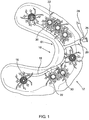
- a schematic illustration of the system for the cleaning and disinfecting of gum surfaces around implants that support dentures (10) is given in Fig. 1 .
- the denture plate (12) used in the system (10) of the present invention is made of standard dentally-used materials and is constructed as a standard fixed-in-place denture with the addition of the components of the system (10) listed above and described below in the text.
- Fig. 1 is an illustration of the system for the cleaning and disinfecting of gum surfaces around implants that support dentures (10) positioned in the gum contact surface side of the denture plate (12), as seen from above.
- the DAILDs (14) and DLSDs (16) are shown discharging liquid to the areas around their circumference.
- the streaming liquid is indicated by arrows (22).
- the liquid enters the system (10) via entry port (20), flows through the conduit (18) and is discharged by the DAILDs (14) and DLSDs (16).
- a liquid-tight stopper (26) reversibly connects to entry port (20).
- stopper (26) In order to inject liquid into the system, stopper (26) is removed from entry port (20) and the liquid is pressured/injected into the conduit (18), typically but not limited to, by a syringe. The empting of the syringe forces the liquid into the conduit (18). After the liquid injection, stopper (26) is re-connects to entry port (20). The liquid stream that enters the system (10) is designated by arrow (28).
- Fig. 2 isometric illustration, seen from the side of a DAILD (14) shown in an assembled configuration.
- Fig. 3 is an isometric illustration, seen from the side, of a DAILD (14) in a disassembled configuration.
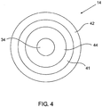
- Fig. 4 is an illustration, seen from above, of a DAILD (14), shown in Fig. 2 .
- Each DAILD (14) is composed of: a hallow-tube dental implant structure (30), a locking component (32), a basin-structure (38) and fastening-component (40).
- Dental implant structure (30) is made of a rigid material hollow-tube that is embedded and fixated in the alveolar of the wearer (the fixation in the alveolar not shown in the figures).
- the locking-structure (32) is constructed of: 1) implant tube connection tube (34), 2) a dome structure (36) having a flat bottom-side 3) a tube (37) that connects and protrudes from the bottom-side of dome structure (36).
- inside tube (37) is a protruding threaded screw (not shown) that fits into the inner-side screw thread of tube (39), as explained later in the text.
- Basin-structure (38) is composed of a circular liquid container (42) with a hollow tube (44) that runs through it. Tube (44) protrudes from the bottom, closed- side, of the container (42). A gap is left between tube (44) and the wall of container (42), designated (41).
- the wall of container (42) has an opening (46) that connects to the conduit (18) by a sub-element of the conduit, designated (48) in Fig. 3 (see in Fig. 10A element b).
- Fastening-component (40) is constructed of a hollow tube (39) that has an expanded portion at one of its ends (39a) and on its other end, a hole (designated: 39b).
- the inner side of component (40), from opening 39b towards expanded-portion (39a), has a screw thread (not seen) that matches the screw inside tube (37).
- fastening-component (40) runs through hollow tube (44) of basin-structure (38) and inserts into tube (37) of locking-structure (32).
- the screw (not shown) inside tube (37) inserts into hole (39(b) in tube (39) in fastening-structure (40) and is interlocked in the screw thread inside tube (39) (not seen).
- Dental implant structure (30) which is embedded in the alveolar of the denture wearer, interlocks and is fixated with implant tube connection tube (34).
- each of the DAILDs (14) In fixating in place of each of the DAILDs (14) in a denture plate (12), a hole is drilled through the denture plate for each DAILDs (14). Fastening-component (40) is inserted through the hole in the denture plate (12), expanded portion (39a) of tube (39) prevents tube (39) from "escaping" from the hole. Tube (39) that was inserted into the hole in denture plate (12) is inserted through tube (44) of basin-structure (38) and into tube (37) of locking-structure (32). The screw inside tube (37) interlocks with the screw threads inside tube 39. By tightening the screw inside tube (37) each of the DAILDs (14) is rigidly fixated into the denture plate (12) structure. By inserting and fixating implant tube connection tube (34) in dental implant structure (30), denture-plate (12), with system (10) is fixated in place in contact with the surfaces of the gums of the denture wearer.
- FIG. 4 illustrates an DAIL as seen from above.
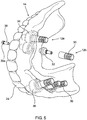
- Fig. 5 is an isometric illustration, seen from above, of DAILDs (14) fixated into the denture plate (12).
- DAIL-s (14) are shown in an assembled (12a) and disassembled (12b) configuration.
- the rim of the walls of container (42) of the DAILDs (14) (shown in Fig. 2, Fig. 3 and Fig.4 ) are fixated into the denture plate (12) so as to be in a smooth alignment with the surface of the denture plate (12).
- the alignment of the DAILDs (14) enables to minimize the gaps between the denture plate (12) and the gums.
- the path of conduit (18) that streams the liquid from port (26) to the DAILDs (14) (and optionally, to the DLSD (16)), as well as the cavities in which the DAILDs (14) and DLSDs (16) are imbedded in the denture plate (12) are illustrated in Fig. 1 .
- the path and cavities are predefined structures that are "dug in” into the surface of the denture plate (12) in a manner that the conduit (18), the DAILDs (14) and the DLSDs (16) form a smooth alignment configuration with the with the gum-contact-surface of the denture plate (12).
- the term "dug in” refers to a predefined channel(s) and cavities formed by etching or/and drilling and/or pre-casting into the surface of the denture plate (12).
- the predefined "dug in” structures in the denture plate as well as the DLSDs (16), the DAILDs (14) and the conduit (18) are designed and manufactured by hand or/and designed and manufactured by a computerized system.
- the liquid that exits from gaps (41) is dispensed in the area surrounding the DAILDs (14).
- the dispensed liquid starts by cleaning and disinfecting the areas immediately surrounding the alveolar imbedded dental implant structures (30) and proceeds to clean and disinfect farther areas of the denture plate (14), as illustrated in Fig. 1 .
- the structure of the DLSDs (16) is presently explained:
- the DLSDs (16) are optional liquid (or gas) dispensers that complement the cleaning and disinfecting functions of the DAILDs (14) and do not have a gum-denture connection function.
- the structure and function of the DLSDs (16) is clarified in: Fig. 1 and Fig. 6A, Fig. 6B .
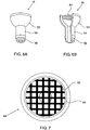
- Fig. 6A is an isometric illustration, seen from the side, of a DLSD (16)
- Fig.6B is an isometric cross cut illustration of the DLSD (16), shown in Fig 5A
- Fig. 7 is an illustration, seen from above, of a DLSD (16), shown in Fig. 6A .
- the DLSDs (16) are composed of a hollow half-sphere component (52) connected in its open-side to sieve plate (64).
- Sieve plate (64) is constructed of a sieve (66) made of a rigid material, fixated in place by a rigid material rim-frame (65).
- a tube (54) protrudes from the bottom of the half-sphere (52).
- the tip of bar (54) is made of protruding rings (56), which enable the connection of the DLSDs (16) to conduit (18), as illustrated in Fig. 1 .
- the DLSDs (16) are fixated into the denture plate (12) so that the sieve plates (64) are in smooth alignment with the surface of the denture plate (12).
- Tubes (54) of the DLSDs (16) connect to conduit (18), which is in smooth alignment with the surface of the denture plate (12), as was previously explained.
- Liquid entering the half-sphere component (52) of the DLSDs (16) from conduit (18) fills the component (52) and overflows.
- the overflown liquid exits through sieve plate (64) and is dispensed in the area surrounding the DLSDs (16), as illustrated in Fig. 1 .
- Liquid injected into port (26) flows through conduit (18) and is dispensed simultaneously from the DAILDs (14) and the DLSDs (16), as illustrated in Fig. 1 . While the primary objective of deploying the DAILDs (14) is the cleaning and disinfecting the immediate surrounding areas of the dental implant structures (30) in the gum of the denture wearer, the objective of deploying the DLSDs (16) is to complement the cleaning and disinfecting of the areas of the gum cleaned by the DAILDs (14) beyond the immediate surrounding areas of the dental implants structures (30).
- the conduit streaming system (61) is composed of the connection of:
- Fig. 8A is an isometric illustration, seen from the side, of a liquid inlet funnel (20) that streams liquid into the conduit (18)
- Fig. 8B is a crosscut isometric illustration, seen from the side, of the liquid inlet funnel (20) shown in Fig. 8A
- the funnel is constructed of a connection-element (58), to which a tube, a syringe or other means of injecting a liquid into conduit (18) connects and a hollow bar (54) that protrudes from connection-element (58).
- the tip of bar (54) is made of protruding rings (56) which enable the connection of the hollow bar (54) to conduit (18).
- Liquid inlet funnel (20) is inserted through a predefined hole in the denture-plate (12), thus, connecting the connection-element (58) via hollow bar (54) to the conduit (18) in the denture plate (12), as illustrated in Fig. 1 .
- Fig. 9A is an isometric illustration, seen from the side, of a liquid stopper (26) in the shape of a thimble.
- Fig. 9B is a crosscut isometric illustration of the liquid stopper (26) shown in Fig. 9A .
- Stopper (26) is inserted and removed into and from connection-element (58) of the liquid inlet funnel (20) at will and is utilized for preventing liquid from flowing from the conduit (18) or for (when removed) to inject liquid into the conduit, respectively.
- the use of liquid stopper (26) s illustrated in Fig. 1 .
- Fig. 10A and Fig 10B illustrate four types of hollow components, that, when assembled in connected-configurations, construct conduit (18).
- Component (49) has a "cross configuration"
- component (48) has a “T” configuration
- component (49) has an “L” configuration
- component (50) has a straight-tube configuration. All four components are constructed of hollow-tubes made of semi-rigid material.
- the designing, manufacturing and assembling of the components that construct the DLSF (14) and DLSD) (16) requires elaborate designing (tailored-made components, in some cases) and delicate manufacturing-precision.
- DAIL (14), the a conduit liquid streaming system and the DLSD (16) can be hand-designed and manufactured but typically the System (10) is designed and manufactured by a computerized controlled system.
Landscapes
- Health & Medical Sciences (AREA)
- Dentistry (AREA)
- Epidemiology (AREA)
- Life Sciences & Earth Sciences (AREA)
- Animal Behavior & Ethology (AREA)
- General Health & Medical Sciences (AREA)
- Public Health (AREA)
- Veterinary Medicine (AREA)
- Oral & Maxillofacial Surgery (AREA)
- Orthopedic Medicine & Surgery (AREA)
- Dental Prosthetics (AREA)
- Apparatus For Disinfection Or Sterilisation (AREA)
Claims (5)
- System (10) für das Reinigen und Desinfizieren von Zahnfleischoberflächen, die Implantate umgeben, die Zahnprothesen lagern, wobei das System (10) umfasst:eine Zahnprothesenplatte (12) mit einer glatten Zahnfleischkontaktoberfläche,wenigstens einen Zahnprothesen-Alveolar-Implantat-Flüssigkeitsspender (DAILD) (14) undein Leitungsflüssigkeits-Strömungssystem (61),wobei jedes der DAILD (14) umfasst:eine Zahnimplantatstruktur (30),eine Verriegelungskomponente (32),eine Beckenstruktur (38) undBefestigungskomponente (40),wobei das Leitungsflüssigkeits-Strömungssystem (61) eine verbundene Anordnung röhrenförmiger Komponenten umfasst, die eine Leitung (18), die Verriegelungskomponente (32),Beckenstruktur (38) und Befestigungskomponente (40) des DAILD (14) errichten, und das Leitungsflüssigkeits-Strömungssystem in die Zahnprothesenplatte (12) eingebettet ist und die Zahnimplantatstruktur (30) in das Alveolar des Trägers der Zahnprothesenplatte (12) implantierbar ist,wobei die Zahnimplantatstruktur (30) eine hohle Röhre umfasst,wobei die Verriegelungskomponente (32) eine Platte umfasst, wobei die Platte aufweist auf ihrer einen Seite eine vorstehende Stange (34), um eine feste Verbindung mit der hohlen Röhre in dem Zahnimplantat herzustellen, und auf ihrer anderen Seite eine hohle Röhre (37), um eine feste Verbindung mit der Befestigungskomponente (40) herzustellen, wobei die fixierten Verbindungen der Verriegelungskomponente (32) ausgelegt sind, die Zahnprothesenplatte (12) in einem fixierten Kontakt mit dem Zahnfleisch des Zahnprothesenträgers zu halten, und ausgelegt sind, enge Lücken zwischen dem Zahnfleisch und der Zahnfleischkontaktfläche der Zahnprothesenplatte (12) zu lassen,wobei die Beckenstruktur (38) aus einem Zylindergefäß (42) mit einer offenen Seite und einer Röhre (44) zusammengesetzt ist, die durch die Mitte des Gefäßes verläuft,wobei die Befestigungskomponente (40) aus einer Stange (39) mit einer Ausdehnung (39a) der Stange (39) an einem der Enden der Stange (39) zusammengesetzt ist,wobei die Beckenstruktur (38) in die Zahnprothesenplatte (12) eingebettet ist und an Ort undStelle in der Zahnprothesenplatte (12) durch die Befestigungskomponente (40) fixiert ist, die durch die Zahnprothesenplatte (12) durch die Röhre (44) in der Beckenstruktur (38) verläuft undfest mit der Verriegelungskomponente (32) verbindet indem es eingeführt wird in die hohle Röhre (37) in der Verriegelungskomponente (32),wobei das Leitungsflüssigkeits-Strömungssystem zu dem Zylindergefäß (42) der Beckenstruktur (38) verbindet,wobei Flüssigkeit, injiziert in das Leitungsflüssigkeits-Strömungssystem, das Zylindergefäß (42) der Beckenstruktur (38) erreicht und von dem Rand des Zylindergefäßes fließt,wobei der Flüssigkeitsstrom angepasst ist, den unmittelbar umgebenden Bereich des DAILD (14) in der Zahnprothesenplatte (12) und in dem unmittelbar umgebenden Bereich der Zahnimplantatstruktur (30) zu reinigen und zu desinfizieren.
- System (10) für das Reinigen und Desinfizieren von Zahnfleischoberflächen, die Implantate umgeben, die Zahnprothesen lagern nach Anspruch 1, wobei die Verriegelungskomponente (32), Beckenstruktur (38) und Befestigungskomponente (40) des DAILD (14) sowie das Leitungsflüssigkeits-Strömungssystem (61) eingebettet sind in die Zahnprothesenplatte (12), um eine glatte Ausrichtungskonfiguration des DAILD (14) und das Leitungsflüssigkeits-Strömungssystem (61) mit der Zahnfleischkontaktoberfläche der Zahnprothesenplatte (12) zu bilden.
- System (10) für das Reinigen und Desinfizieren von Zahnfleischoberflächen, die Implantate umgeben, die Zahnprothesen lagern nach Anspruch 1, wobei das Leitungsflüssigkeits-Strömungssystem eine Flüssigkeitseintrittsöffnung (20) mit einer Trommelkonfiguration aufweist.
- System (10) für das Reinigen und Desinfizieren von Zahnfleischoberflächen, die Implantate umgeben, die Zahnprothesen lagern nach Anspruch 1, wobei das System auch zusätzlich zu dem wenigstens einen DAILD (14) wenigstens einen Zahnprothesen-Flüssigkeits-Siebspender, abgekürzt als DLSD (16) umfasst,
wobei der DLSD (16) umfasst:eine hohle Halbkugel-Gefäßkomponente (52), die in ihrer offenen Seite mit einer Siebplattenkomponente (64) und mit einer Störröhre (54) von dem Boden der Halbkugel-Gefäßkomponente (52) verbunden ist,wobei der DLSD (16) in die Zahnprothesenplatte (12) eingebettet ist, um eine glatte Ausrichtungskonfiguration des DLSD (16) mit der Zahnfleischkontaktoberfläche der Zahnprothesenplatte (12) zu bilden, wobei das Leitungsflüssigkeits-Strömungssystem zu der Störröhre der Halbkugel-Gefäßkomponente (52) verbindet,wobei Flüssigkeit, injiziert in das Leitungsflüssigkeits-Strömungssystem, die Halbkugel-Gefäßkomponente (52) erreicht und durch die Siebplattenkomponente (64) zu dem umgebenden Bereich fließt, dadurch reinigend und desinfizierend den Bereich, der den DLSD (16) umgibt. - System (10) für das Reinigen und Desinfizieren von Zahnfleischoberflächen, die Implantate umgeben, die Zahnprothesen lagern nach Anspruch 4, wobei das Leitungs-Strömungssystem (61), der DAILD (14) und der DLSD (16) für das Reinigen und Desinfizieren durch Strömen eines Gases ausgelegt sind.
Applications Claiming Priority (2)
| Application Number | Priority Date | Filing Date | Title |
|---|---|---|---|
| US201662359212P | 2016-07-07 | 2016-07-07 | |
| PCT/IL2017/000004 WO2018008011A1 (en) | 2016-07-07 | 2017-07-02 | A system for the cleaning and disinfecting of gum surfaces surrounding implant structures that support dentures |
Publications (3)
| Publication Number | Publication Date |
|---|---|
| EP3481329A1 EP3481329A1 (de) | 2019-05-15 |
| EP3481329A4 EP3481329A4 (de) | 2020-02-26 |
| EP3481329B1 true EP3481329B1 (de) | 2021-05-26 |
Family
ID=60912469
Family Applications (1)
| Application Number | Title | Priority Date | Filing Date |
|---|---|---|---|
| EP17823756.6A Active EP3481329B1 (de) | 2016-07-07 | 2017-07-02 | System zur reinigung und desinfektion von zahnfleischoberflächen um zahnprothesen-tragende implantatstrukturen herum |
Country Status (5)
| Country | Link |
|---|---|
| US (2) | US10918468B2 (de) |
| EP (1) | EP3481329B1 (de) |
| CN (1) | CN109789003B (de) |
| IL (1) | IL263666B (de) |
| WO (1) | WO2018008011A1 (de) |
Families Citing this family (1)
| Publication number | Priority date | Publication date | Assignee | Title |
|---|---|---|---|---|
| DE102017119189B4 (de) * | 2017-08-22 | 2020-06-18 | Kulzer Gmbh | Suprakonstruktion und prothetische Versorgung mit integriertem Reinigungssystem |
Family Cites Families (17)
| Publication number | Priority date | Publication date | Assignee | Title |
|---|---|---|---|---|
| US3379192A (en) * | 1965-05-10 | 1968-04-23 | Lamar G. Warren Jr. | Dental treatment device |
| GB9723826D0 (en) | 1997-11-11 | 1998-01-07 | Procter & Gamble | A denture cleaning apparatus |
| US6390104B1 (en) | 2000-05-19 | 2002-05-21 | Steven P. Gagnon | Denture wash |
| AU2002345101B2 (en) * | 2001-06-12 | 2006-09-14 | Stick Tech Oy | A prepreg, a composite and their uses |
| US6893259B1 (en) * | 2004-03-08 | 2005-05-17 | Igor Reizenson | Oral hygiene device and method of use therefor |
| GR1005447B (el) | 2006-05-15 | 2007-02-20 | Λαζαρος Ξανθοπουλος | Ηλεκτρονικα ρυθμιζομενη συσκευη καθαρισμου, απολυμανσης και περιποιησης οδοντοστοιχιων |
| US20080272153A1 (en) | 2007-05-03 | 2008-11-06 | Bruce Hochstadter | System and method for delivering liquid to a mouth of a user |
| US8202090B2 (en) | 2008-02-29 | 2012-06-19 | Pharmaco-Kinesis Corporation | Artificial tooth medicating apparatus for controlling, regulating, sensing, and releasing medical agents into the body |
| DE102008029086B4 (de) | 2008-06-20 | 2012-01-19 | Group Vander Kerken Van Der Veken N.V. | Stabilisator für Zahnprothesen |
| GB201113041D0 (en) * | 2011-07-28 | 2011-09-14 | King S College London | Mouth guard |
| WO2013030835A1 (en) * | 2011-08-29 | 2013-03-07 | David Regev | Dental implant system and methods for accessing intra cavity areas therethrough |
| WO2013060563A1 (en) * | 2011-10-25 | 2013-05-02 | Universität Bern | Device for treating gingiva/ mucosa at teeth or implants |
| GB2502767B (en) | 2012-03-21 | 2017-12-06 | Knight Martin | Cannula |
| BR112015010747B1 (pt) | 2012-11-14 | 2020-12-08 | Zyfoma Gmbh | elemento de tratamento para o uso com uma peça de implante dentário e sistema de tratamento |
| US11116609B2 (en) * | 2013-06-06 | 2021-09-14 | Abracadabra Implants Ltd | Dental implant device, system and method of use |
| US9801700B1 (en) * | 2014-11-17 | 2017-10-31 | Janusz Liberkowski | Dental prosthesis with sealed attachment interface and cleaning fluid access thereto |
| CN204446160U (zh) * | 2015-02-09 | 2015-07-08 | 耿汝杰 | 口腔修复清洗消毒装置 |
-
2017
- 2017-07-02 EP EP17823756.6A patent/EP3481329B1/de active Active
- 2017-07-02 WO PCT/IL2017/000004 patent/WO2018008011A1/en not_active Ceased
- 2017-07-02 US US16/314,451 patent/US10918468B2/en not_active Expired - Fee Related
- 2017-07-02 CN CN201780048588.XA patent/CN109789003B/zh not_active Expired - Fee Related
-
2018
- 2018-12-12 IL IL263666A patent/IL263666B/en unknown
-
2021
- 2021-02-12 US US17/174,867 patent/US20210161630A1/en not_active Abandoned
Non-Patent Citations (1)
| Title |
|---|
| None * |
Also Published As
| Publication number | Publication date |
|---|---|
| EP3481329A1 (de) | 2019-05-15 |
| WO2018008011A1 (en) | 2018-01-11 |
| CN109789003A (zh) | 2019-05-21 |
| CN109789003B (zh) | 2021-08-27 |
| EP3481329A4 (de) | 2020-02-26 |
| US20210161630A1 (en) | 2021-06-03 |
| US20190247171A1 (en) | 2019-08-15 |
| IL263666B (en) | 2022-04-01 |
| IL263666A (en) | 2019-01-31 |
| US10918468B2 (en) | 2021-02-16 |
Similar Documents
| Publication | Publication Date | Title |
|---|---|---|
| EP1633272B1 (de) | Periodontale medikamenten-abgabeschale | |
| US6638064B1 (en) | Flexible endodontic syringe | |
| RU2567272C2 (ru) | Зубной имплантат (варианты) | |
| US20030013064A1 (en) | Rinsing cannula for rinsing a root canal of a tooth | |
| KR101959774B1 (ko) | 외부 주수 장치를 구비하는 치아 임플란트 시술용 서지컬 가이드 시스템 | |
| JP2019509071A (ja) | マルチカニューレ負圧洗浄システム | |
| JPH03261469A (ja) | 口腔内衛生装置 | |
| CN1809323A (zh) | 注射成型的根管治疗刷 | |
| US20210161630A1 (en) | System for the cleaning and disinfecting of gum surfaces surrounding implant structures that support dentures | |
| Dawood et al. | Peri-implantitis and the prosthodontist | |
| KR101803847B1 (ko) | 임플란트 픽스처 세척장치 | |
| CN102048589B (zh) | 一种复合种植牙构件 | |
| DE4340598A1 (de) | Ultraschall-Zahnbürste | |
| JPH0654867A (ja) | 端部がフレキシブルな潅注プローブ | |
| KR100781967B1 (ko) | 신경성장인자 공급용 임플란트 | |
| CN214342762U (zh) | 一种种植修复吸潮纸棒 | |
| El Askary | Use of a titanium papillary insert for the construction of interimplant papillae | |
| KR20040086889A (ko) | 구강대 | |
| WO2015122788A1 (en) | An applicator mounted in a dental implant seat | |
| RU2200503C1 (ru) | Мостовидный протез для замещения малых включенных дефектов зубного ряда | |
| WO2024052894A2 (en) | A dental implant assembly | |
| KR20240063612A (ko) | 치과 임플란트 | |
| DE10259579A1 (de) | Vorrichtung zur Reinigung der Zähne und Zahnzwischenräume | |
| Amza et al. | Contributions regarding FEM for an ultrasonic endodontic device and his appliance in the root canal treatments | |
| AMZA et al. | Ultrasonic treatment endodontice |
Legal Events
| Date | Code | Title | Description |
|---|---|---|---|
| STAA | Information on the status of an ep patent application or granted ep patent |
Free format text: STATUS: THE INTERNATIONAL PUBLICATION HAS BEEN MADE |
|
| PUAI | Public reference made under article 153(3) epc to a published international application that has entered the european phase |
Free format text: ORIGINAL CODE: 0009012 |
|
| STAA | Information on the status of an ep patent application or granted ep patent |
Free format text: STATUS: REQUEST FOR EXAMINATION WAS MADE |
|
| 17P | Request for examination filed |
Effective date: 20190103 |
|
| AK | Designated contracting states |
Kind code of ref document: A1 Designated state(s): AL AT BE BG CH CY CZ DE DK EE ES FI FR GB GR HR HU IE IS IT LI LT LU LV MC MK MT NL NO PL PT RO RS SE SI SK SM TR |
|
| AX | Request for extension of the european patent |
Extension state: BA ME |
|
| DAV | Request for validation of the european patent (deleted) | ||
| DAX | Request for extension of the european patent (deleted) | ||
| REG | Reference to a national code |
Ref country code: DE Ref legal event code: R079 Ref document number: 602017039396 Country of ref document: DE Free format text: PREVIOUS MAIN CLASS: A61C0017000000 Ipc: A61C0017020000 |
|
| A4 | Supplementary search report drawn up and despatched |
Effective date: 20200129 |
|
| RIC1 | Information provided on ipc code assigned before grant |
Ipc: A61C 8/00 20060101ALI20200123BHEP Ipc: A61C 13/01 20060101ALI20200123BHEP Ipc: A61C 17/02 20060101AFI20200123BHEP |
|
| GRAP | Despatch of communication of intention to grant a patent |
Free format text: ORIGINAL CODE: EPIDOSNIGR1 |
|
| STAA | Information on the status of an ep patent application or granted ep patent |
Free format text: STATUS: GRANT OF PATENT IS INTENDED |
|
| INTG | Intention to grant announced |
Effective date: 20210115 |
|
| GRAS | Grant fee paid |
Free format text: ORIGINAL CODE: EPIDOSNIGR3 |
|
| GRAA | (expected) grant |
Free format text: ORIGINAL CODE: 0009210 |
|
| STAA | Information on the status of an ep patent application or granted ep patent |
Free format text: STATUS: THE PATENT HAS BEEN GRANTED |
|
| AK | Designated contracting states |
Kind code of ref document: B1 Designated state(s): AL AT BE BG CH CY CZ DE DK EE ES FI FR GB GR HR HU IE IS IT LI LT LU LV MC MK MT NL NO PL PT RO RS SE SI SK SM TR |
|
| REG | Reference to a national code |
Ref country code: GB Ref legal event code: FG4D |
|
| REG | Reference to a national code |
Ref country code: CH Ref legal event code: EP |
|
| REG | Reference to a national code |
Ref country code: AT Ref legal event code: REF Ref document number: 1395445 Country of ref document: AT Kind code of ref document: T Effective date: 20210615 |
|
| REG | Reference to a national code |
Ref country code: DE Ref legal event code: R096 Ref document number: 602017039396 Country of ref document: DE |
|
| REG | Reference to a national code |
Ref country code: IE Ref legal event code: FG4D |
|
| REG | Reference to a national code |
Ref country code: LT Ref legal event code: MG9D |
|
| REG | Reference to a national code |
Ref country code: AT Ref legal event code: MK05 Ref document number: 1395445 Country of ref document: AT Kind code of ref document: T Effective date: 20210526 |
|
| PG25 | Lapsed in a contracting state [announced via postgrant information from national office to epo] |
Ref country code: LT Free format text: LAPSE BECAUSE OF FAILURE TO SUBMIT A TRANSLATION OF THE DESCRIPTION OR TO PAY THE FEE WITHIN THE PRESCRIBED TIME-LIMIT Effective date: 20210526 Ref country code: FI Free format text: LAPSE BECAUSE OF FAILURE TO SUBMIT A TRANSLATION OF THE DESCRIPTION OR TO PAY THE FEE WITHIN THE PRESCRIBED TIME-LIMIT Effective date: 20210526 Ref country code: AT Free format text: LAPSE BECAUSE OF FAILURE TO SUBMIT A TRANSLATION OF THE DESCRIPTION OR TO PAY THE FEE WITHIN THE PRESCRIBED TIME-LIMIT Effective date: 20210526 Ref country code: BG Free format text: LAPSE BECAUSE OF FAILURE TO SUBMIT A TRANSLATION OF THE DESCRIPTION OR TO PAY THE FEE WITHIN THE PRESCRIBED TIME-LIMIT Effective date: 20210826 Ref country code: HR Free format text: LAPSE BECAUSE OF FAILURE TO SUBMIT A TRANSLATION OF THE DESCRIPTION OR TO PAY THE FEE WITHIN THE PRESCRIBED TIME-LIMIT Effective date: 20210526 |
|
| REG | Reference to a national code |
Ref country code: NL Ref legal event code: MP Effective date: 20210526 |
|
| PG25 | Lapsed in a contracting state [announced via postgrant information from national office to epo] |
Ref country code: GR Free format text: LAPSE BECAUSE OF FAILURE TO SUBMIT A TRANSLATION OF THE DESCRIPTION OR TO PAY THE FEE WITHIN THE PRESCRIBED TIME-LIMIT Effective date: 20210827 Ref country code: IS Free format text: LAPSE BECAUSE OF FAILURE TO SUBMIT A TRANSLATION OF THE DESCRIPTION OR TO PAY THE FEE WITHIN THE PRESCRIBED TIME-LIMIT Effective date: 20210926 Ref country code: PT Free format text: LAPSE BECAUSE OF FAILURE TO SUBMIT A TRANSLATION OF THE DESCRIPTION OR TO PAY THE FEE WITHIN THE PRESCRIBED TIME-LIMIT Effective date: 20210927 Ref country code: LV Free format text: LAPSE BECAUSE OF FAILURE TO SUBMIT A TRANSLATION OF THE DESCRIPTION OR TO PAY THE FEE WITHIN THE PRESCRIBED TIME-LIMIT Effective date: 20210526 Ref country code: PL Free format text: LAPSE BECAUSE OF FAILURE TO SUBMIT A TRANSLATION OF THE DESCRIPTION OR TO PAY THE FEE WITHIN THE PRESCRIBED TIME-LIMIT Effective date: 20210526 Ref country code: NO Free format text: LAPSE BECAUSE OF FAILURE TO SUBMIT A TRANSLATION OF THE DESCRIPTION OR TO PAY THE FEE WITHIN THE PRESCRIBED TIME-LIMIT Effective date: 20210826 Ref country code: SE Free format text: LAPSE BECAUSE OF FAILURE TO SUBMIT A TRANSLATION OF THE DESCRIPTION OR TO PAY THE FEE WITHIN THE PRESCRIBED TIME-LIMIT Effective date: 20210526 Ref country code: RS Free format text: LAPSE BECAUSE OF FAILURE TO SUBMIT A TRANSLATION OF THE DESCRIPTION OR TO PAY THE FEE WITHIN THE PRESCRIBED TIME-LIMIT Effective date: 20210526 |
|
| PG25 | Lapsed in a contracting state [announced via postgrant information from national office to epo] |
Ref country code: NL Free format text: LAPSE BECAUSE OF FAILURE TO SUBMIT A TRANSLATION OF THE DESCRIPTION OR TO PAY THE FEE WITHIN THE PRESCRIBED TIME-LIMIT Effective date: 20210526 |
|
| PG25 | Lapsed in a contracting state [announced via postgrant information from national office to epo] |
Ref country code: ES Free format text: LAPSE BECAUSE OF FAILURE TO SUBMIT A TRANSLATION OF THE DESCRIPTION OR TO PAY THE FEE WITHIN THE PRESCRIBED TIME-LIMIT Effective date: 20210526 Ref country code: SK Free format text: LAPSE BECAUSE OF FAILURE TO SUBMIT A TRANSLATION OF THE DESCRIPTION OR TO PAY THE FEE WITHIN THE PRESCRIBED TIME-LIMIT Effective date: 20210526 Ref country code: SM Free format text: LAPSE BECAUSE OF FAILURE TO SUBMIT A TRANSLATION OF THE DESCRIPTION OR TO PAY THE FEE WITHIN THE PRESCRIBED TIME-LIMIT Effective date: 20210526 Ref country code: RO Free format text: LAPSE BECAUSE OF FAILURE TO SUBMIT A TRANSLATION OF THE DESCRIPTION OR TO PAY THE FEE WITHIN THE PRESCRIBED TIME-LIMIT Effective date: 20210526 Ref country code: EE Free format text: LAPSE BECAUSE OF FAILURE TO SUBMIT A TRANSLATION OF THE DESCRIPTION OR TO PAY THE FEE WITHIN THE PRESCRIBED TIME-LIMIT Effective date: 20210526 Ref country code: CZ Free format text: LAPSE BECAUSE OF FAILURE TO SUBMIT A TRANSLATION OF THE DESCRIPTION OR TO PAY THE FEE WITHIN THE PRESCRIBED TIME-LIMIT Effective date: 20210526 Ref country code: DK Free format text: LAPSE BECAUSE OF FAILURE TO SUBMIT A TRANSLATION OF THE DESCRIPTION OR TO PAY THE FEE WITHIN THE PRESCRIBED TIME-LIMIT Effective date: 20210526 |
|
| REG | Reference to a national code |
Ref country code: DE Ref legal event code: R097 Ref document number: 602017039396 Country of ref document: DE |
|
| PLBE | No opposition filed within time limit |
Free format text: ORIGINAL CODE: 0009261 |
|
| STAA | Information on the status of an ep patent application or granted ep patent |
Free format text: STATUS: NO OPPOSITION FILED WITHIN TIME LIMIT |
|
| PG25 | Lapsed in a contracting state [announced via postgrant information from national office to epo] |
Ref country code: MC Free format text: LAPSE BECAUSE OF FAILURE TO SUBMIT A TRANSLATION OF THE DESCRIPTION OR TO PAY THE FEE WITHIN THE PRESCRIBED TIME-LIMIT Effective date: 20210526 |
|
| REG | Reference to a national code |
Ref country code: BE Ref legal event code: MM Effective date: 20210731 |
|
| 26N | No opposition filed |
Effective date: 20220301 |
|
| PG25 | Lapsed in a contracting state [announced via postgrant information from national office to epo] |
Ref country code: IS Free format text: LAPSE BECAUSE OF FAILURE TO SUBMIT A TRANSLATION OF THE DESCRIPTION OR TO PAY THE FEE WITHIN THE PRESCRIBED TIME-LIMIT Effective date: 20210926 Ref country code: LU Free format text: LAPSE BECAUSE OF NON-PAYMENT OF DUE FEES Effective date: 20210702 Ref country code: AL Free format text: LAPSE BECAUSE OF FAILURE TO SUBMIT A TRANSLATION OF THE DESCRIPTION OR TO PAY THE FEE WITHIN THE PRESCRIBED TIME-LIMIT Effective date: 20210526 |
|
| PG25 | Lapsed in a contracting state [announced via postgrant information from national office to epo] |
Ref country code: IT Free format text: LAPSE BECAUSE OF FAILURE TO SUBMIT A TRANSLATION OF THE DESCRIPTION OR TO PAY THE FEE WITHIN THE PRESCRIBED TIME-LIMIT Effective date: 20210526 Ref country code: IE Free format text: LAPSE BECAUSE OF NON-PAYMENT OF DUE FEES Effective date: 20210702 Ref country code: BE Free format text: LAPSE BECAUSE OF NON-PAYMENT OF DUE FEES Effective date: 20210731 |
|
| PGFP | Annual fee paid to national office [announced via postgrant information from national office to epo] |
Ref country code: GB Payment date: 20220830 Year of fee payment: 6 Ref country code: DE Payment date: 20220823 Year of fee payment: 6 |
|
| PGFP | Annual fee paid to national office [announced via postgrant information from national office to epo] |
Ref country code: FR Payment date: 20220830 Year of fee payment: 6 |
|
| PGFP | Annual fee paid to national office [announced via postgrant information from national office to epo] |
Ref country code: CH Payment date: 20220928 Year of fee payment: 6 |
|
| PG25 | Lapsed in a contracting state [announced via postgrant information from national office to epo] |
Ref country code: CY Free format text: LAPSE BECAUSE OF FAILURE TO SUBMIT A TRANSLATION OF THE DESCRIPTION OR TO PAY THE FEE WITHIN THE PRESCRIBED TIME-LIMIT Effective date: 20210526 |
|
| PG25 | Lapsed in a contracting state [announced via postgrant information from national office to epo] |
Ref country code: HU Free format text: LAPSE BECAUSE OF FAILURE TO SUBMIT A TRANSLATION OF THE DESCRIPTION OR TO PAY THE FEE WITHIN THE PRESCRIBED TIME-LIMIT; INVALID AB INITIO Effective date: 20170702 |
|
| REG | Reference to a national code |
Ref country code: DE Ref legal event code: R119 Ref document number: 602017039396 Country of ref document: DE |
|
| REG | Reference to a national code |
Ref country code: CH Ref legal event code: PL |
|
| GBPC | Gb: european patent ceased through non-payment of renewal fee |
Effective date: 20230702 |
|
| PG25 | Lapsed in a contracting state [announced via postgrant information from national office to epo] |
Ref country code: MK Free format text: LAPSE BECAUSE OF FAILURE TO SUBMIT A TRANSLATION OF THE DESCRIPTION OR TO PAY THE FEE WITHIN THE PRESCRIBED TIME-LIMIT Effective date: 20210526 Ref country code: DE Free format text: LAPSE BECAUSE OF NON-PAYMENT OF DUE FEES Effective date: 20240201 Ref country code: GB Free format text: LAPSE BECAUSE OF NON-PAYMENT OF DUE FEES Effective date: 20230702 Ref country code: CH Free format text: LAPSE BECAUSE OF NON-PAYMENT OF DUE FEES Effective date: 20230731 |
|
| PG25 | Lapsed in a contracting state [announced via postgrant information from national office to epo] |
Ref country code: FR Free format text: LAPSE BECAUSE OF NON-PAYMENT OF DUE FEES Effective date: 20230731 |
|
| PG25 | Lapsed in a contracting state [announced via postgrant information from national office to epo] |
Ref country code: TR Free format text: LAPSE BECAUSE OF FAILURE TO SUBMIT A TRANSLATION OF THE DESCRIPTION OR TO PAY THE FEE WITHIN THE PRESCRIBED TIME-LIMIT Effective date: 20210526 |
|
| PG25 | Lapsed in a contracting state [announced via postgrant information from national office to epo] |
Ref country code: MT Free format text: LAPSE BECAUSE OF FAILURE TO SUBMIT A TRANSLATION OF THE DESCRIPTION OR TO PAY THE FEE WITHIN THE PRESCRIBED TIME-LIMIT Effective date: 20210526 |