EP3481135B1 - Verfahren und vorrichtung zum konfigurieren von dualkonnektivität - Google Patents
Verfahren und vorrichtung zum konfigurieren von dualkonnektivität Download PDFInfo
- Publication number
- EP3481135B1 EP3481135B1 EP17820554.8A EP17820554A EP3481135B1 EP 3481135 B1 EP3481135 B1 EP 3481135B1 EP 17820554 A EP17820554 A EP 17820554A EP 3481135 B1 EP3481135 B1 EP 3481135B1
- Authority
- EP
- European Patent Office
- Prior art keywords
- rrc
- lte
- master
- entity
- pdcp
- Prior art date
- Legal status (The legal status is an assumption and is not a legal conclusion. Google has not performed a legal analysis and makes no representation as to the accuracy of the status listed.)
- Active
Links
Images


Classifications
-
- H—ELECTRICITY
- H04—ELECTRIC COMMUNICATION TECHNIQUE
- H04W—WIRELESS COMMUNICATION NETWORKS
- H04W28/00—Network traffic management; Network resource management
- H04W28/02—Traffic management, e.g. flow control or congestion control
- H04W28/0252—Traffic management, e.g. flow control or congestion control per individual bearer or channel
-
- H—ELECTRICITY
- H04—ELECTRIC COMMUNICATION TECHNIQUE
- H04W—WIRELESS COMMUNICATION NETWORKS
- H04W28/00—Network traffic management; Network resource management
- H04W28/02—Traffic management, e.g. flow control or congestion control
- H04W28/08—Load balancing or load distribution
- H04W28/082—Load balancing or load distribution among bearers or channels
-
- H—ELECTRICITY
- H04—ELECTRIC COMMUNICATION TECHNIQUE
- H04W—WIRELESS COMMUNICATION NETWORKS
- H04W72/00—Local resource management
- H04W72/20—Control channels or signalling for resource management
- H04W72/21—Control channels or signalling for resource management in the uplink direction of a wireless link, i.e. towards the network
-
- H—ELECTRICITY
- H04—ELECTRIC COMMUNICATION TECHNIQUE
- H04W—WIRELESS COMMUNICATION NETWORKS
- H04W76/00—Connection management
- H04W76/10—Connection setup
- H04W76/15—Setup of multiple wireless link connections
-
- H—ELECTRICITY
- H04—ELECTRIC COMMUNICATION TECHNIQUE
- H04W—WIRELESS COMMUNICATION NETWORKS
- H04W76/00—Connection management
- H04W76/20—Manipulation of established connections
- H04W76/27—Transitions between radio resource control [RRC] states
-
- H—ELECTRICITY
- H04—ELECTRIC COMMUNICATION TECHNIQUE
- H04L—TRANSMISSION OF DIGITAL INFORMATION, e.g. TELEGRAPHIC COMMUNICATION
- H04L45/00—Routing or path finding of packets in data switching networks
- H04L45/16—Multipoint routing
-
- H—ELECTRICITY
- H04—ELECTRIC COMMUNICATION TECHNIQUE
- H04W—WIRELESS COMMUNICATION NETWORKS
- H04W28/00—Network traffic management; Network resource management
- H04W28/02—Traffic management, e.g. flow control or congestion control
- H04W28/10—Flow control between communication endpoints
- H04W28/12—Flow control between communication endpoints using signalling between network elements
-
- H—ELECTRICITY
- H04—ELECTRIC COMMUNICATION TECHNIQUE
- H04W—WIRELESS COMMUNICATION NETWORKS
- H04W88/00—Devices specially adapted for wireless communication networks, e.g. terminals, base stations or access point devices
- H04W88/02—Terminal devices
- H04W88/06—Terminal devices adapted for operation in multiple networks or having at least two operational modes, e.g. multi-mode terminals
Definitions
- the present disclosure relates to a method and a device for transmitting and receiving data when a user equipment (UE) configures dual connectivity with a plurality of Base Stations (BSs) or cells that use different radio access technologies.
- UE user equipment
- BSs Base Stations
- a current mobile communication system has employed technologies related to 3 rd generation partnership project (3GPP), for example, Long Term Evolution (LTE), LTE-Advanced (LTE-A), 5G, and the like.
- 3GPP 3 rd generation partnership project
- LTE Long Term Evolution
- LTE-A LTE-Advanced
- 5G 5th Generation
- 3GPP 3 rd generation partnership project
- a method of using a small cell for transmitting and receiving data a method of simultaneously using a macrocell having a wide coverage and a small cell having a relatively small coverage for transmitting and receiving data and a method for simultaneously using a plurality of base stations for transmitting and receiving data.
- next generation radio access network technology has been developed, many users still use terminals and base stations employing the legacy network technologies. Accordingly, it is required to provide a related service supporting the legacy network and the next generation network together.
- the dual connectivity technology enables a terminal to maintain connection with two or more base stations. Since the next generation radio access technology supports base stations employing different network technologies, it is required to redesign the dual connectivity technology to support different network technologies (radio access technologies (RATs)).
- RATs radio access technologies
- Document US2015/215965A1 discloses a method for receiving a radio resource control (RRC) message by a user equipment (UE).
- the method includes receiving, from a first evolved Node B (eNB), an RRC connection reconfiguration (RRCConnectionReconfiguration) message including data radio bearer (DRB) configuration parameters for remapping a DRB that is established on a master cell group (MCG) to a secondary cell group (SCG).
- eNB evolved Node B
- RRCConnectionReconfiguration RRC connection reconfiguration
- DRB data radio bearer
- an aspect of the present disclosure is to provide a detailed procedure and operations for enabling a user equipment (UE) to perform dual connectivity using a plurality of Base Stations (BSs).
- UE user equipment
- BSs Base Stations
- an aspect of the present disclosure is to provide a detailed operation of transmitting data using a split bearer when a UE and BSs configure dual connectivity.
- a method according to claim 1 is provided for transmitting and receiving data by a user equipment (UE) that configures dual connectivity.
- UE user equipment
- a UE according claim 4 as defined in the set of claims is provided for configuring dual connectivity.
- a user equipment is enabled to configure dual connectivity using a plurality of Base Stations (BSs) that use different radio access technologies.
- BSs Base Stations
- a UE is enabled to configure dual connectivity using BSs that use different radio access technologies and to perform operation without an error when transmitting and receiving uplink data and downlink data.
- a machine type communication (MTC) terminal refers to a terminal that is low cost (or is not very complexity), a terminal that supports coverage enhancement, or the like.
- the MTC terminal refers to a terminal that supports low cost (or low complexity) and coverage enhancement.
- the MTC terminal refers to a terminal that is defined as a predetermined category for maintaining low costs (or low complexity) and/or coverage enhancement.
- the MTC terminal may refer to a newly defined 3GPP Release 13 low cost(or low complexity) UE category/type, which executes LTE-based MTC related operations.
- the MTC terminal may refer to a UE category/type that is defined in or before 3GPP Release -12 that supports the enhanced coverage in comparison with the typical LTE coverage, or supports low power consumption, or may refer to a newly defined Release 13 low cost(or low complexity) UE category/type.
- a wireless communication system may be widely installed to provide various communication services, such as a voice service, a packet data service, and the like.
- the wireless communication system may include a User Equipment (UE) and a Base Station (BS or an eNB).
- the user equipment may be an inclusive concept indicating a user terminal utilized in wireless communication, including a UE (User Equipment) in wideband code division multiple access (WCDMA), long-term evolution (LTE), high speed packet access (HSPA), and the like, and an MS (Mobile station), a UT (Use Terminal), an SS (Subscriber Station), a wireless device, and the like in global systems for mobile communication (GSM).
- WCDMA wideband code division multiple access
- LTE long-term evolution
- HSPA high speed packet access
- MS Mobile station
- UT User Terminal
- SS Subscriber Station
- GSM global systems for mobile communication
- a base station or a cell may generally refer to a station that performs communication with a User Equipment (UE).
- the base station or cell may also be referred to as a Node-B, an evolved Node-B (eNB), a Sector, a Site, a Base Transceiver System (BTS), an Access Point, a Relay Node, a Remote Radio Head (RRH), a Radio Unit (RU), and the like.
- the base station or the cell may be construed as an inclusive concept indicating a portion of an area covered by a BSC (Base Station Controller) in CDMA, a NodeB in WCDMA, an eNB or a sector (site) in LTE, and the like, and the concept may include various coverage areas, such as a megacell, a macrocell, a microcell, a picocell, a femtocell, a communication range of a relay node, and the like.
- BSC Base Station Controller
- the base station may be a device that provides a megacell, a macrocell, a microcell, a picocell, a femtocell, and a small cell in association with a wireless area, or ii) the base station may indicate a wireless area itself.
- a base station may be all devices that are controlled by one identical entity or that cooperate with each other for providing a predetermined wireless service area.
- the base station may be referred to as an eNB, an RRH, an antenna, an RU, a Low Power Node (LPN), a point, a transmission/reception point, a transmission point, a reception point, and the like.
- a base station may be a wireless service area itself that enables a terminal or a neighboring base station to receive or transmit a signal.
- a megacell a macrocell, a microcell, a picocell, a femtocell, a small cell, an RRH, an antenna, an RU, an LPN, a point, an eNB, a transmission/reception point, a transmission point, and a reception point are commonly referred to as a base station.
- the user equipment and the base station are used as two inclusive transceiving subjects to embody the technology and technical concepts described in the present disclosure, but embodiments thereof may not be limited to a predetermined term or word.
- the user equipment and the base station are used as two (uplink or downlink) inclusive transceiving subjects to embody the technology and technical concepts described in the specifications, but embodiments of the present disclosure may not be limited to a predetermined term or word.
- Uplink (UL) refers to a scheme for a UE to transmit and receive data to/from a base station
- DL refers to a scheme for a base station to transmit and receive data to/from a UE.
- Varied multiple access schemes may be unrestrictedly applied to the wireless communication system.
- Various multiple access schemes may include CDMA (Code Division Multiple Access), TDMA (Time Division Multiple Access), FDMA (Frequency Division Multiple Access), OFDMA (Orthogonal Frequency Division Multiple Access), OFDM-FDMA, OFDM-TDMA, OFDM-CDMA, and the like.
- Embodiments of the present disclosure may be applicable to resource allocation in an asynchronous wireless communication scheme that is advanced to LTE and LTE-advanced through GSM, WCDMA, and HSPA and may be applicable to resource allocation in a synchronous wireless communication scheme that is advanced to UMB through CDMA and CDMA-2000.
- the present disclosure may not be limited to a specific wireless communication field and may include all technical fields in which the technical idea of the present disclosure is applicable.
- Uplink transmission and downlink transmission may be performed based on i) a TDD (Time Division Duplex) scheme that performs transmission based on different times or ii) an FDD (Frequency Division Duplex) scheme that performs transmission based on different frequencies.
- TDD Time Division Duplex
- FDD Frequency Division Duplex
- a standard related to LTE and LTE-A defines an uplink and a downlink to be configured based on a single carrier or a pair of carriers.
- the uplink and the downlink may transmit control information through a control channel, such as a PDCCH (Physical Downlink Control CHannel), a PCFICH (Physical Control Format Indicator CHannel), a PHICH (Physical Hybrid ARQ Indicator CHannel), a PUCCH (Physical Uplink Control CHannel), an EPDCCH(Enhanced Physical Downlink Control CHannel), and the like.
- the uplink and the downlink may transmit data through a data channel, such as a PDSCH (Physical Downlink Shared CHannel), a PUSCH (Physical Uplink Shared CHannel), and the like.
- Control information may be transmitted using an EPDCCH (enhanced PDCCH or extended PDCCH).
- EPDCCH enhanced PDCCH or extended PDCCH.
- a cell may refer to the coverage of a signal transmitted from a transmission/reception point, a component carrier having the coverage of the signal transmitted from the transmission/reception point (transmission point or transmission/reception point), or the transmission/reception point itself.
- a wireless communication system refers to a Coordinated Multi-point transmission/reception (CoMP) system where two or more transmission/reception points cooperatively transmit a signal, a coordinated multi-antenna transmission system, or a coordinated multi-cell communication system.
- CoMP system may include at least two multi-transmission/reception points and terminals.
- a multi-transmission/reception point may be i) a base station or ii) a macro cell (hereinafter, referred to as an 'eNB') and at least one RRH that is connected to the eNB through an optical cable or an optical fiber, is wiredly controlled, and has a high transmission power or a low transmission power within a macro cell area.
- an 'eNB' a macro cell
- a downlink refers to communication or a communication path from a multi-transmission/reception point to a terminal
- an uplink refers to communication or a communication path from a terminal to a multi-transmission/reception point.
- a transmitter may be a part of a terminal and a receiver may be a part of a multiple transmission/reception point.
- a transmitter may be a part of a terminal and a receiver may be a part of a multiple transmission/reception point.
- signal transmission and reception through a PUCCH, a PUSCH, a PDCCH, or a PDSCH may be described as transmission and reception of a PUCCH, a PUSCH, a PDCCH, or a PDSCH.
- a PDCCH is transmitted or received, or a signal is transmitted or received through a PDCCH
- the expression “a PDCCH is transmitted or received, or a signal is transmitted or received through a PDCCH” includes “an EPDCCH is transmitted or received, or a signal is transmitted or received through an EPDCCH”.
- a physical downlink control channel may indicate one of a PDCCH, an EPDCCH, and both a PDCCH and an EPDCCH.
- An EPDCCH according to an embodiment of the present disclosure may be applied to another embodiment described using a PDCCH.
- higher layer signaling includes an RRC signaling that transmits RRC information including an RRC parameter.
- An eNB executes downlink transmission to terminals.
- the eNB may transmit a Physical Downlink Shared Channel (PDSCH) which is a primary physical channel for unicast transmission and may transmit a Physical Downlink Control Channel (PDCCH) for transmitting downlink control information, such as scheduling required for reception of a PDSCH, and scheduling grant information for transmission of an uplink data channel (for example, a Physical Uplink Shared Channel (PUSCH)).
- PDSCH Physical Downlink Shared Channel
- PUSCH Physical Uplink Shared Channel
- the legacy LTE technology supports dual connectivity for enabling a user equipment to use radio resources of two Base Stations (BSs) together.
- the dual connectivity may enable multiple RX/TX UEs in the RRC-connected state to use radio resources provided by two different schedulers connected to two BSs which are connected via non-ideal backhaul.
- a user equipment may provide a service via two BSs.
- the UE may perform communication using a master BS (MeNB) and a secondary BS (SeNB).
- the MeNB may be a BS that provides an RRC connection to the UE and that is the base of handover.
- the SeNB may bea BS that provides additional radio resources to the UE.
- a SeNB addition procedure for setting UE context at the SeNB may be used in order to provide SeNB radio resources to the UE.
- FIG. 1 is a signal flow diagram illustrating a SeNB addition procedure according to a related art.
- the UE 100 may apply the new configuration, as shown in operation S103.
- the UE 100 may perform a reconfiguration failure procedure.
- the MeNB 110 is capable of understanding a radio resource control (RRC) message of the SeNB 120. Also, by taking into consideration the UE capabilities and the coordination with the SeNB 120, the MeNB 110 may generate a final RRC message and may indicate the same to the UE 100, whereby radio resources based on two BSs are effectively used.
- the RRC message may be provided via a wireless interface between the UE 100 and the MeNB 110.
- NR next generation radio access technology
- the RAN architecture may need to support tight interworking between NR and LTE.
- LTE dual connectivity may be expected to be reused.
- NR as new radio access technology may employ various evolved features on a physical layer, a layer 2 protocol, and a procedure. Therefore, it is realistically difficult that an LTE BS supports all the features of NR which are to be evolved in the future, when the tight interwork between LTE and NR is supported.
- Updating an LTE BS every time that an NR BS evolves may be an excessive burden to the LTE BS which has already been configured. Therefore, in dual connectivity configured by an LTE BS and an NR BS, the LTE BS needs to be capable of operating even through the LTE BS does not understand an RRC message generated by the NR BS. In this instance, since the NR BS is incapable of identifying a change in the radio resource configuration of the NR BS, the LTE BS may have difficulty performing UE configuration within UE capabilities.
- an RRC message is transmitted only via an MeNB.
- the radio resource configuration information of the SeNB may be configured for a UE via the MeNB. Therefore, a transmission delay between BSs may be always added when a radio resource of the NR BS is changed.
- NR may be established even in a high-frequency band (e.g., a 6 GHz or more high-frequency band).
- a high-frequency band e.g., a 6 GHz or more high-frequency band.
- quick SINR drops may occur. That may cause a delay when the NR BS desires to send an RRC message via the interface between NR and a UE.
- the dual connectivity technology based on the legacy LTE is configured for a UE on the basis of the coordination between two LTE BSs. Accordingly, it is difficult to directly apply the dual connectivity technology based on the legacy LTE to the dual connectivity technology between LTE and NR.
- the NR BS is incapable of directly transmitting an RRC message to a UE after the generating the RRC message. Even through the NR BS generates and directly transmits the RRC message to a UE, an RRC message transmission delay may occur when the NR BS uses a high-frequency band.
- the present disclosure derived in order to overcome the above-described problems, is to provide a method and apparatus for processing a radio resource control signaling of an NR BS for an LTE-NR dual connectivity operation that supports tight interwork between LTE and NR. Also, the present disclosure is to provide a method of a BS for distinctively processing RRC messages using two different radio access links.
- the present disclosure may be applied to a UE in the next generation mobile communication (e.g., 5G mobile communication), in addition to a UE in LTE mobile communication.
- next generation mobile communication e.g., 5G mobile communication
- a BS may indicate an LTE BS, which is an eNodeB of LTE/E-UTRAN.
- BS may indicate a gNodeB, or an NR node or NR BS (a central unit (CU), a distribute unit (DU), or an entity in which a CU and a DU are implemented as a single logical entity, and hereinafter it is referred to as an NR BS for ease of description but above-described all entities are included in the scope of the present disclosure) in the 5G wireless network in which the CU and the DU is separated.
- CU central unit
- DU distribute unit
- the LTE BS may be described as a master BS and the NR BS may be described as a secondary BS, as it is needed.
- the present disclosure is applicable to the dual connectivity between LTE BSs and thus, may be applied equally when the secondary BS is an LTE BS.
- an LTE BS and an NR BS may be compartmentalized, and when it is needed to specifically describe the operation based on dual connectivity, the LTE BS is described as a master BS (MeNB) and the NR BS is described as a secondary BS (SeNB).
- MeNB master BS
- SeNB secondary BS
- the name of each BS is for ease of understanding, and the LTE BS may indicate an eNB, and the NR BS may indicate a gNB. That is, the present disclosure compartmentally describes BSs in order to distinguish BSs that use different radio access technologies, but the embodiments of the present disclosure are not limited to those terms.
- dual connectivity is used for ease of description, but providing two or more connectivity is included in the scope of the present disclosure.
- the present disclosure may provide descriptions using the case of LTE (Master Node) - NR (Secondary Node), which is able to use the well configured LTE coverage.
- LTE Master Node
- NR Secondary Node
- NR(Master Node) - LTEb(Secondary Node) are included in the scope of the present disclosure.
- An NR BS may control NR radio resources of a UE.
- an LTE BS may control NR radio resources of a UE.
- the NR BS may perform one or more control functions among i) a function of adding (modifying, releasing, or managing) an NR cell (a cell group, a transmission point, a transmission point group, a transmission and reception point, a transmission and reception point group, a TRP, an antenna, an antenna group, or a beam (hereinafter referred to as a cell)), ii) an NR measurement function, iii) an NR measurement reporting function, iv) an NR resource allocation function, v) an NR radio bearer addition/modification/release function, vi) an NR radio resource configuration function, and vii) an NR mobility control function.
- the NR BS may instruct one or more of the above-described control functions to a UE via an RRC configuration or reconfiguration message.
- each of an LTE RRC entity of the LTE BS and an NR RRC entity of the NR BS may independently indicate a corresponding BS radio resource control configuration.
- the LTE RRC entity of the LTE BS may independently instruct a corresponding BS radio resource control configuration via the interface between LTE and the UE
- the NR RRC entity of the NR BS may independently instruct a corresponding BS radio resource control configuration via the interface between NR and the UE.
- each of the LTE RRC entity of the LTE BS and the NR RRC entity of the NR BS may independently instruct a corresponding BS radio resource control configuration within the scope of UE capabilities.
- each of the LTE RRC entity of the LTE BS and the NR RRC entity of the NR BS may instruct a corresponding BS radio resource control configuration via coordination.
- the LTE RRC entity of the LTE BS may instruct an LTE BS radio resource control configuration via an LTE radio link and an NR radio link.
- the NR RRC entity of the NR BS may instruct an LTE BS radio resource control configuration via an NR radio link and an LTE radio link.
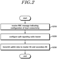
- FIG. 2 is a flowchart illustrating operations of a UE according to an embodiment.
- a UE that configures dual connectivity receives from a master BS, an RRC message instructing configuration of dual connectivity using the master BS and a secondary BS, in operation S210.
- the RRC message may include configuration information such that the UE configures dual connectivity using the master BS and the secondary BS which are based on different access technologies.
- the configuration information may include cell information, cell group information, RRC connection information, and the like associated with the master BS and the secondary BS.
- the RRC message includes information instructing duplicated transmission of uplink data using a split signaling radio bearer at a packet data convergence protocol (PDCP) entity of the UE.
- the RRC message may include information for setting a data transmission path of a split signaling radio bearer.
- the UE configures a split signaling radio bearer (Split SRB) connected to two cells or cell groups, in order to configure dual connectivity, in operation S220.
- split SRB split signaling radio bearer
- the UE may configure a split signaling radio bearer connected to a cell associated with the master BS and to a cell associated with the secondary BS.
- the UE configures a split signaling radio bearer connected to a master cell group including one or more cells associated with the master BS and to a secondary cell group including one or more cells associated with the secondary BS.
- the split signaling radio bearer may be configured via links of the master BS and the secondary BS to the UE and may be different from a bearer connected only via the master BS and a bearer connected only via the secondary BS. Also, the split signaling radio bearer may be configured by being split from the PDCP entity of the master BS or the PDCP entity of the secondary BS.
- the UE performs duplicated transmission of uplink data to each of the master BS and the secondary BS via the split signaling radio bearer in operation S230.
- the packet data convergence protocol (PDCP) entity of the UE may transfer a PDCP protocol data unit (PDCP PDU) generated by duplicating a PDCP service data unit (PDCP SDU) including the uplink data, to radio link control (RLC) entities which are configured to be connected to the master BS and the secondary BS, respectively. That is, the UE may include an RLC entity configured to peer with the master BS and an RLC entity configured to peer with the secondary BS.
- PDCP PDU PDCP protocol data unit
- RLC radio link control
- the UE may transfer, to two RLC entities, a PDCP PDU associated with the same data using a PDCP entity.
- Each RLC entity may transfer the uplink data to the RLC entity of each of the master BS and the secondary BS. That is, the same uplink data may be duplicately transmitted via a master BS link and a secondary BS link.
- the present disclosure describes, as an RLC entity, the layer 2 entity of the NR BS that performs all or some of the functions performed by the RLC entity of the LTE BS, the embodiments of the present disclosure are not limited to the name of the entity.
- the packet data convergence protocol (PDCP) entity of the UE may transfer a PDCP service data unit (PDCP SDU) including the uplink data to a radio link control (RLC) entity configured to be connected to the master cell group or the secondary cell group.
- PDCP SDU PDCP service data unit
- RLC radio link control
- the UE may duplicately receive downlink data via the master BS and the secondary BS.
- the packet data convergence protocol (PDCP) entity of the UE may discard any one of the downlink data duplicately received from the master BS and the secondary BS via a split signaling radio bearer.
- the PDCP entity of the UE may discard any one of the data having the same sequence number from among the duplicately received downlink data.
- the master BS and the secondary BS described in the above descriptions are BSs that use different radio access technologies.
- the master BS is an LTE eNB
- the secondary BS is an NR gNB.
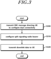
- FIG. 3 is a flowchart illustrating operations of a BS.
- a master BS that transmits and receives data via dual connectivity transmits an RRC message instructing a UE to configure dual connectivity using the master BS and a secondary BS in operation S300.
- the RRC message may include configuration information for directing the UE to configure dual connectivity using the master BS and the secondary BS which employ different access technologies.
- the configuration information may include cell information, cell group information, RRC connection information, and the like associated with the master BS and the secondary BS.
- the RRC message may include information instructing a packet data convergence protocol (PDCP) entity of a UE to perform duplicated transmission of uplink data using a split signaling radio bearer.
- the RRC message may include information for setting the data transmission path of a split signaling radio bearer.
- the master BS configures a split signaling radio bearer (split SRB) connected to a secondary BS in order to configure dual connectivity in operation S310.
- split SRB split signaling radio bearer
- the master BS may configure a split signaling radio bearer connected to the cell of the master BS and the cell associated with the secondary BS.
- the master BS may configure a split signaling radio bearer connected to a master cell group including one or more cells associated with the master BS and to a secondary cell group including one or more cells associated with the secondary BS.
- the split signaling radio bearer may be configured via links of the master BS and the secondary BS to the UE and may be different from a bearer connected only via the master BS and a bearer connected only via the secondary BS. Also, the split signaling radio bearer may be configured by being split from the PDCP entity of the master BS or the PDCP entity of the secondary BS.
- the master BS may perform duplicated transmission of downlink data to the UE via the split signaling radio bearer, at a packet data convergence protocol (PDCP) of the master BS, in operation S320.
- PDCP packet data convergence protocol
- the PDCP entity of the master BS may transfer a PDCP protocol data unit (PDCP PDU) generated by duplicating a PDCP service data unit (PDCP SDU) including downlink data to an RLC entity of the master BS and an RLC entity of the secondary BS.
- PDCP PDU PDCP protocol data unit
- PDCP SDU PDCP service data unit
- the master BS may transmit the same downlink data to the RLC entities of the master BS and the secondary BS, thereby performing duplicated transmission to the UE.
- the present disclosure describes, as an RLC entity, the layer 2 entity of the NR BS that performs all or some of the functions performed by the RLC entity of the LTE BS, the embodiments of the present disclosure are not limited to the name of the entity.
- the packet data convergence protocol (PDCP) entity of the master BS may transfer a PDCP service data unit (PDCP SDU) including the downlink data to a radio link control (RLC) entity configured to be connected to the master cell group or the secondary cell group.
- PDCP SDU PDCP service data unit
- RLC radio link control
- the PDCP entity of the master BS may discard any one of the uplink data duplicately received from the UE via a split signaling radio bearer. For example, the PDCP entity of the master BS may discard any one of the data having the same sequence number from among the duplicately received uplink data. Through the above, data transferred to the upper of the PDCP entity may be transferred without duplication.
- the master BS and the secondary BS described in the above descriptions are BSs that use different radio access technologies.
- the master BS is an LTE eNB
- the secondary BS is an NR gNB.
- the UE may duplicately transmit uplink data or duplicately receive downlink data via a split signaling radio bearer.
- the BS may set a data transmission path via the split signaling radio bearer.
- the PDCP entities of the UE and the master BS may perform duplicated transmission and may perform operations for discarding the duplicately received data.
- each of an LTE RRC entity of an LTE BS and an NR RRC entity of an NR BS may independently indicate a corresponding BS radio resource control configuration.
- each of the LTE RRC entity of the LTE BS and the NR RRC entity of the NR BS may instruct a corresponding BS radio resource control configuration via coordination.
- the LTE RRC entity of the LTE BS may instruct an LTE BS radio resource control configuration via an LTE radio link and an NR radio link.
- the NR RRC entity of the NR BS may instruct an NR BS radio resource control configuration via the NR radio link and the LTE radio link.
- an NR RRC entity of the UE may transmit an NR RRC message to the NR BS via the NR radio link and the LTE radio link.
- an LTE RRC entity of the UE may transmit an NR RRC message to the NR BS via the LTE radio link and the NR radio link.
- each BS or a UE transmits one RRC message via two radio links by reason of reliable RRC message transmission (or for an arbitrary reason)
- the BS or the UE needs to transmit the RRC message via two radio links and a counterpart UE (or a counterpart BS) needs to receive and process the same distinctively.
- the following methods may be used independently or in combination.
- embodiments of the present disclosure will be described based on an NR BS (or a UE) and a counterpart UE (or a counterpart NR BS) that perform transmission and reception (e.g., in the case of transmitting an NR RRC message via two paths)for convenience of description and ease of understanding.
- the embodiments of the present disclosure are not limited thereto.
- the embodiments may be applicable when an LTE BS (or a UE) and a counterpart UE (or a counterpart LTE BS) perform transmission and reception (e.g., the case of transferring an LTE RRC message via two paths and the case of transferring an RRC message of an MeNB to the interface between the MeNB and a UE and to the interface between an SeNB and the UE).
- LTE BS or a UE
- counterpart BS e.g., the case of transferring an LTE RRC message via two paths and the case of transferring an RRC message of an MeNB to the interface between the MeNB and a UE and to the interface between an SeNB and the UE.
- An NR RRC entity of an NR BS (or a UE) generates an NR RRC message.
- the generated NR RRC message is transferred via NR-SRB 1 such that the NR RRC message is transferred to the radio link between the NR BS and the UE.
- the NR RRC entity of the NR BS (or the UE) may transfer the NR RRC message to the UE (or NR RRC) via the LTE BS.
- the NR BS RRC entity of the NR BS
- the LTE BS (or the RRC entity of the LTE BS) may transfer the NR RRC container/NR RRC lEs/an RRC message including NR RRC IEs to the UE (or the LTE RRC entity of the UE) via an LTE SRB (LTE SRB1).
- LTE SRB1 LTE SRB1
- the LTE RRC may include, in an RRC reconfiguration message, the NR RRC container/NR RRC IEs/RRC message including NR RRC IEs as a transparent container and may transfer the same to the UE.
- information for instructing sending a radio link path of a single uplink RRC message through two radio links may be included in the RRC message and may be configured for the UE.
- information for instructing duplication of a single uplink RRC message and transmission of the duplicated uplink RRC messages via two links may be included in the RRC message and may be configured for the UE.
- information instructing transmitting a radio link path of an uplink RRC message may be included in the RRC message and configured for the UE.
- information for instructing duplication of a single uplink RRC message and transmission of the duplicated uplink RRC messages via two radio links may be included in the RRC message and may be configured for the UE.
- an NR RRC entity of an NR BS (or a UE) generates an NR RRC message.
- the generated NR RRC message is transferred via NR-splitSRB1 such that the NR RRC message is transferred to the radio link between the NR BS and the UE and the radio link between the LTE BS and the UE.
- the same may be submitted to a lower layer.
- the NR RRC entity of the NR BS (or the UE) transfers the generated NR RRC message to a PDCP entity (an upper L2 entity).
- the PDCP entity (the upper L2 entity) duplicates a PDCP SDU including the NR RRC message.
- a PDCP PDU including one NR RRC message is transferred to an LTE RLC entity.
- a PDCP PDU including the other NR RRC message is transferred to an NR L2 entity.
- information for instructing enablement of a function for transmitting PDCP data including an uplink RRC message via two radio links at the PDCP may be included in an RRC message and may be configured for the UE.
- information for instructing duplication of a PDCP SDU/PDU such that a PDCP (upper L2 entity) transmits PDCP data including an uplink RRC message via two radio links and/or indicating submission of the same to each associated lower layer entity may be included in an RRC message and may be configured for the UE.
- information indicating a radio link path of an uplink RRC message may be included in an RRC message and may be configured for the UE.
- the same duplicated PDCP data may be discarded by a PDCP entity that peers.
- the BS may indicate, to the UE, information instructing discarding duplicated PDCP PDU/SDU including the same RRC message and may configure the same for the UE.
- the NR RRC entity of the NR BS (or the UE) generates an NR RRC message.
- the NR RRC message may be duplicated.
- the NR RRC entity transmits the generated NR RRC message via NR-splitSRB 1 in order to transfer the same to the radio link between the NR BS and the UE and the radio link between the LTE BS and the UE.
- the NR RRC is submitted to a lower layer.
- the NR RRC entity of the NR BS (or the UE) transfers the generated NR RRC message to a PDCP entity (an upper L2 entity).
- the PDCP entity may transmit a PDCP SDU including an RRC message received earlier and a PDCP SDU including an RRC message received subsequently, via different paths (an LTE BS radio link and an NR BS radio link).
- the NR BS is described as a mater BS.
- the embodiments of the present disclosure are not limited thereto.
- the embodiments of the present disclosure may be equally applied when the LTE BS is a master BS, as described in FIGs. 2 and 3 .
- the PDCP entity of the LTE BS may configure a split SRB.
- the PDCP entity of the LTE BS may duplicate and discard PDCP data.
- a transmitting end transmits an RRC message via two radio links, and a receiving end may identify duplicated RRC messages, which are the same RRC message received via the two radio links. The receiving end may discard/drop/remove/scrap the duplicated RRC message.
- a BS may configure information in order to instruct the same to a UE.
- the transmitting end may include identification information in the RRC message for identifying the same RRC message.
- the identification information for identifying an RRC message may be increased as a new RRC message is generated. After the largest value is used for identification information, the smallest value is cyclically used again for identification information. For example, when a value is in the range from 0 to 3 (or 1 to 4), the value for a first RRC message is 0 (or 1), and the value for a subsequent RRC message is increased by one. When the value of an RRC message reaches 3 (or 4), a subsequent RRC message may be cyclically 0 (or 1) again.
- the receiving end may discard/drop/remove/scarp the corresponding RRC message.
- the receiving end may transmit a confirmation message associated with the same to the transmitting end.
- the BS configures, for the UE, information for indicating that RRC message identification information is included in an RRC message.
- the UE may recognize that the RRC message identification information is included.
- a transmitting end transmits an RRC message via two radio links, and a receiving end may identify duplicated RRC messages, which are the same RRC message received via the two radio links. The receiving end may discard/drop/remove/scrap the duplicated RRC message.
- a BS may configure information in order to indicate the same to a UE.
- the duplicated RRC message may be identified using the transaction identifier included in the RRC message, and the duplicated RRC message may be discarded/dropped/removed/scrapped.
- the UE may set, in a response message, an RRC transaction identifier that is the same as an RRC transaction identifier included in a message received from the BS which triggers the response message.
- the UE may include a transaction identifier in an RRC message that does not trigger a response message and may transmit the same, such that a duplicated RRC message is identified.
- the UE may include a transaction identifier in a Measurement Report message and may transmit the same.
- the UE may include a transaction identifier in all RRC messages and may transmit the same.
- the receiving end may discard/drop/remove/scarp the corresponding RRC message.
- the receiving end may transmit a confirmation message associated with the same to the transmitting end.
- an NR BS may transfer an NR RRC message (e.g., an RRC message generated by an NR BS) to a UE via an LTE BS.
- the NR BS (an RRC entity of the NR BS) may transfer an NR RRC container/NR RRC IEs/NR RRC message including the NR RRC IEs to the LTE BS.
- the LTE BS (or an RRC entity of the LTE BS) may transfer the NR RRC container/NR RRC IEs/an RRC message including NR RRC IEs to the UE (or an RRC entity of the UE) via an LTE SRB.
- the LTE RRC may include, in an RRC reconfiguration message, the NR RRC container/NR RRC IEs/RRC message including NR RRC IEs as a transparent container, and may transfer the same to the UE.
- This method may transmit the RRC configuration information of the NR BS to the UE by minimizing a change of the LTE BS.
- a delay associated with data transmission between the LTE BS and the NR BS increases.
- the NR BS needs to receive a confirmation message associated with the NR RRC configuration of the UE from the LTE BS. This is also a factor that causes a delay.
- the LTE BS may direct the RRC entity of the UE to directly transmit an RRC reconfiguration confirmation message to the NR BS when the LTE BS transfers an NR RRC container/NR RRC IEs/RRC message including NR RRC IEs to the UE (or the RRC entity of the UE).
- the LTE RRC entity of the UE that receives the NR RRC container/NR RRC IEs/RRC message including NR RRC IEs via an LTE SRB may transfer/submit the same to the NR RRC entity.
- the NR RRC entity may apply a new configuration.
- the NR RRC entity may reply with an RRC reconfiguration confirmation message via the interface between the UE and the NR BS.
- the RRC entity of the UE that receives the NR RRC container/NR RRC IEs/RRC message including NR RRC IEs via an LTE SRB may apply a new configuration.
- the RRC entity of the UE may reply with an RRC reconfiguration confirmation message via the interface between the UE and the NR BS.
- the RRC reconfiguration message (or the NR RRC container/NR RRC IEs/RRC message including NR RRC IEs) may include information used for indicating, by the NR BS (or the LTE BS), operations that the UE needs to perform.
- the RRC reconfiguration message (or the NR RRC container/NR RRC IEs/RRC message including NR RRC IEs) may include information used for directing the UE to generate/enable/activate an NR RRC entity.
- the UE may enable the NR RRC entity to enable/activate the NR addition configuration (or the UE may configure/generate an NR RRC entity).
- the UE may disable/deactivate/release an NR RRC entity.
- the RRC reconfiguration message (or the NR RRC container/NR RRC IEs/RRC message including NR RRC IEs) may include information for directing the UE to transmit an RRC confirmation message via the interface between the UE and the NR BS, at the NR RRC entity.
- the RRC reconfiguration message (or the NR RRC container/NR RRC IEs/RRC message including NR RRC IEs) may include NR BS SRB configuration information such that the UE transmits an RRC confirmation message via the interface between the UE and the NR BS, at the NR RRC entity.
- An NR BS transmits an NR RRC message to a UE via the interface between the NR BS and the UE.
- the NR BS configures an SRB (e.g., SRB1) between the UE and the NR BS.
- SRB e.g., SRB1
- SRB 1 is configured in RRC connection setup in the legacy LTE.
- setup of SRB 1 (for ease of descriptions, a signaling radio bearer configured to transmit data via the interface between an NR BS and a UE is referred to as NR-SRB1, it is not limited to the corresponding term.) between the NR BS and the UE is configured via an RRC reconfiguration message that configures LTE-NR dual connectivity (NR additional radio resources).
- all RRC messages on NR-SRB 1 may need to be ciphered and integrity protected by a PDCP (or an L2 entity on NR). It may be understood that the LTE-NR dual connectivity is applied to an RRC connected UE. Therefore, all RRC messages on NR-SRB 1 may need to be ciphered and integrity protected by the PDCP (or (upper) L2 entity on NR).
- the LTE BS needs to avoid setting the corresponding bearer before security for the bearer is activated.
- the LTE BS needs to avoid requesting NR BS addition before security is activated.
- the NR BS may set NR-SRB 1 by request for NR BS addition from the LTE BS.
- the LTE BS when requesting NR BS addition, the LTE BS needs to transfer (or calculate and transfer) an NR BS key (e.g., NR-K BS ) to the NR BS.
- the NR BS may select an integrity protection algorithm and a ciphering algorithm.
- the selected integrity protection algorithm and ciphering algorithm (or identification information of the integrity protection algorithm and the ciphering algorithm) by which NR-SRB 1 is to be serviced to the UE, may be transferred to the UE via the LTE BS.
- the LTE BS (or NR BS) may indicate, to the UE, a counter (an SCG counter or an NR counter) to be used when the UE calculates a key value associated with NR-SRB 1.
- the UE calculates the NR BS key.
- the UE may calculate the key value (NR-K RRCint , NR-K RRCenc ) associated with NR-SRB 1.
- the UE may perform configuration such that a lower layer (a PDCP or L2 entity on NR) applies the integrity protection algorithm, ciphering algorithm, NR-K RRCint , and NR-K RRCenc .
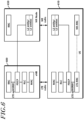
- FIG. 4 is a diagram illustrating a dual connectivity SRB configuration according to an embodiment.
- an L2 entity of NR 450 of FIG. 4 is configured as one or two entities by reallocating the functions of the LTE MAC entity and the RLC entity of LTE 400.
- FIG. 4 illustrates that an LTE-RRC entity and an NR-RRC entity are independently configured in a UE 410.
- the embodiments of the present disclosure are not limited thereto.
- a single RRC entity/layer may be configured in the UE 410 in accordance with anther embodiment of the present disclosure.
- data may be transmitted via NR-SRB 1 in association with an RRC message received from an NR BS 450 and a response RRC message corresponding thereto.
- data may be transmitted via NR-SRB 1 in association with an RRC message received from the NR BS 450 or a response RRC message corresponding thereto.
- the NR BS 450 may preferentially process NR-SRB 1 than a DRB. For example, a predetermined logical channel identification information (logicalchannelIdentity) value may be designated for NR-SRB 1.
- a logical channel identification information (logicalchannelIdentity) value (e.g., 1), which is the same as that of SRB1, may be designated for NR-splitSRB1.
- an SRB identification information (SRB-identity) value (e.g., 1), which is the same as that of SRB1, may be designated for NR-SRB 1.
- a logical channel configuration value (e.g., priority (1 or 2), prioritisedBitRate(infinite)) which is the same as/similar to that of SRB 1 is designated for NR-SRB 1.
- information may be included that enables a UE to identify SCG SRB 1 although logical channel identification information that is the same as that of SRB 1 is included.
- logical channel identification information which is different from that of SRB1
- logical channel configuration information which is the same as that of SRB1 may be included.
- the NR BS 450 may transmit, to the UE 410, an NR RRC message including one or more pieces of control information from among information for adding/modifying/releasing/managing an NR cell/cell group/transmission point/transmission point group/transmission and reception point/transmission and reception point group/TRP/antenna/antenna group/beam, NR measurement information, NR measurement reporting information, NR resource allocation information, NR radio bearer adding/modifying/releasing information, NR radio resource configuration information, and NR mobility control information.
- the NR BS 450 (an RRC entity of the NR BS) may transfer an NR RRC container/NR RRC IEs/NR RRC message including NR RRC IEs to the UE 410 via NR-SRB1.
- the UE may apply a new configuration by using the following methods independently or in combination.
- the NR RRC message may include radio resource configuration information associated with the NR BS.
- the NR RRC message may include secondary BS (NR BS) radio resource configuration information.
- a UE may configure an NR radio resource via an RRC entity.
- an MeNB transmits an RRC message including a new radio resource configuration of an SCG to a UE in the legacy LTE dual connectivity and when the UE is incapable of complying with (a part of) the configuration included in a RRC connection reconfiguration message, the UE performs a reconfiguration failure procedure.
- the reconfiguration failure procedure in LTE is performed as follows.
- the UE When the UE is incapable of complying with (a part of) the configuration included in the RRC connection reconfiguration message, the UE may continuously use the configuration which was used before the reception of the RRC connection reconfiguration message. When security is not activated, the cause of release is set to "other" and an operation of leaving an "RRC_CONNECTED” state may be performed. Otherwise, the UE may initiate a connection re-establishment procedure.
- the reconfiguration failure in the legacy LTE may cause interruption of a service since the UE needs to be switched to an idle mode or an RRC connection reconfiguration procedure needs to be performed.
- the UE may not trigger a reconfiguration failure procedure. That is, the UE may prevent NR RRC configuration failure from triggering LTE RRC configuration failure.
- the UE may transmit an RRC message including the cause of NR RRC configuration failure (e.g., an SCG failure information message, a UE assistance message, or an NR failure information/NR status message to be newly defined) to an NR BS.
- the UE may transmit an RRC message including the cause of NR RRC configuration failure (e.g., an SCG failure information message, a UE assistance message, or an NR failure information/NR status message to be newly defined) to an LTE BS. That is, when the UE fails to configure radio resources of a secondary BS using an RRC message received via an SRB of the secondary BS, the UE may transmit corresponding failure information to a master BS.
- an RRC message including the cause of NR RRC configuration failure e.g., an SCG failure information message, a UE assistance message, or an NR failure information/NR status message to be newly defined
- the received RRC message may include configuration information for configuring an NR radio resource (e.g., one or more piece of information from among NR cell configuration information, NR bearer configuration information, control information for NR random access, NR measurement configuration information, NR mobility control information, and NR radio resource-dedicated configuration information).
- configuration information for adding or modifying an NR BS in dual connectivity or information for reconfiguring NR radio resources via a secondary BS SRB may be described as secondary BS radio resource configuration information, NR radio resource configuration information, NR configuration information, or configuration information.
- an RRCConnectionReconfiguration message that is received via a master BS SRB includes NR radio resource configuration information
- the UE e.g., a UE RRC entity
- the UE may perform NR configuration.
- an RRCConnectionReconfiguration message that is received via a secondary BS SRB includes NR radio resource configuration information
- the UE e.g., a UE RRC entity
- the UE may perform NR configuration.
- the UE may continuously use the (NR) configuration that was used before the reception of the RRC connection reconfiguration message (before the reception of NR configuration information).
- the NR radio resources may include at least one from among a secondary cell group data radio bearer (DRB), a secondary cell group SRB, a secondary cell group part of a split DRB, and a secondary cell group part of a split SRB.
- DRB secondary cell group data radio bearer
- the RRC may transmit an RRC message including the cause of NR RRC configuration failure to an LTE BS.
- the LTE BS may transfer the same to the NRBS.
- the RRC may directly transmit an RRC message including the cause of NR RRC configuration failure to the NR BS via the interface between the UE and the NRBS.
- NR may independently include evolvable features, which are different from those of LTE.
- a UE may configure an LTE RRC and an NR RRC.
- an MeNB transmits an RRC message including a new radio resource configuration of an SCG to a UE in the legacy LTE dual connectivity and when the UE is incapable of complying with (a part of) the configuration included in a RRC connection reconfiguration message, the UE performs a reconfiguration failure procedure.
- the reconfiguration failure procedure in LTE is performed as follows.
- the UE When the UE is incapable of complying with (a part of) the configuration included in the RRC connection reconfiguration message, the UE may continuously use the configuration which was used before the reception of the RRC connection reconfiguration message. When security is not activated, the cause of release is set to "other" and an operation of leaving an "RRC_CONNECTED” state may be performed. Otherwise, the UE may initiate a connection re-establishment procedure.
- the reconfiguration failure in the legacy LTE may cause interruption of a service since the UE needs to be switched to an idle mode or an RRC connection reconfiguration procedure needs to be performed.
- the UE when the UE fails to implement the NR configuration included in the NR RRC message (or is incapable of complying with the NR configuration included in the NR RRC message for any reason), the UE may not trigger a reconfiguration failure procedure.
- the UE may prevent NR RRC configuration failure from triggering LTE RRC configuration failure.
- the UE may transmit an RRC message including the cause of NR RRC configuration failure (e.g., an SCG failure information message, a UE assistance message, or an NR failure information/NR status message to be newly defined) to an NR BS (or an LTE BS).
- the RRC may transmit an RRC message including the cause of NR RRC configuration failure to the LTE BS.
- the LTE BS may transfer the same to the NR BS.
- the UE When a received RRCConnectionReconfiguration message includes configuration information for configuring NR radio resources, the UE (NR RRC) may perform NR configuration.
- the UE may continuously use the (NR) configuration that was used before the reception of RRC connection reconfiguration message (before the NR RRC receives NR configuration information).
- the NR radio resources may include at least one from among a secondary cell group data radio bearer (DRB), a secondary cell group SRB, a secondary cell group part of a split DRB, and a secondary cell group part of a split SRB.
- DRB secondary cell group data radio bearer
- the UE may release NR radio resources.
- the NR RRC may indicate NR reconfiguration failure to an LTE RRC.
- the LTE RRC may transfer an RRC message including the cause of NR RRC configuration failure to the LTE BS.
- the LTE BS may transfer the same to the NR BS.
- the NR RRC may directly transmit an RRC message including the cause of NR RRC configuration failure to the NR BS via the interface between the UE and the NR BS.
- the UE may indicate NR physical layer failure to an RRC entity.
- the RRC entity may indicate an RRC message including the cause of NR physical layer failure to an LTE BS via an LTE SRB.
- NR may include wireless communication features different from the features of LTE, and an LTE BS may not understand an RRC message generated by an NR BS.
- the NR BS may directly transmit, to a UE, an NR RRC message including one or more pieces of control information from among information for adding/modifying/releasing/managing an NR cell/cell group/transmission point/transmission point group/transmission and reception point/transmission and reception point group/TRP/antenna/antenna group/beam, NR measurement information, NR measurement reporting information, NR resource allocation information, NR radio bearer adding/modifying/releasing information, NR radio resource configuration information; and NR mobility control information.
- NR may be established even in a high-frequency band (e.g., a 6 GHz or more high-frequency band).
- a problem may occur when an NR RRC is transmitted.
- an NR RRC message may be transmitted using both the interface between the NR BS and the UE and the interface between the LTE BS and the UE.
- FIG. 5 is a diagram illustrating a dual connectivity SRB configuration according to another embodiment.
- an NR BS 550 may configure an SRB (e.g., SRB1 type) which enables the UE 510 to use both an LTE BS 500 and the NR BS 550.
- SRB e.g., SRB1 type
- NR-splitSRB 1 a signaling radio bearer configured, by an NR BS, to use both an LTE BS and the NR BS is described as NR-splitSRB 1
- NR-splitSRB 1 a signaling radio bearer configured, by an NR BS, to use both an LTE BS and the NR BS
- RRC reconfiguration message that (re)configures LTE-NR dual connectivity (that configures NR additional radio resources).
- all RRC messages on NR-splitSRB 1 may need to be ciphered and integrity protected by a PDCP (or an L2 entity on NR). It may be understood that the LTE-NR dual connectivity is applied to the RRC connected UE 510. Therefore, all RRC messages on NR-splitSRB1 may need to be ciphered and integrity protected by the PDCP (or (upper) L2 entity on NR).
- the NR BS 550 needs to avoid configuring the bearer before security is activated.
- the LTE BS 500 needs to avoid requesting addition of the NR BS 550 before security is activated.
- the NR BS 550 needs to avoid requesting addition of NRsplitSRB1 from the LTE BS 500 before security is activated.
- the NR BS 550 may configure NR-splitSRB 1 according to a request for NR BS addition from the LTE BS 500.
- the NR BS 550 may configure NR-splitSRB 1 as needed.
- the LTE BS 500 needs to transfer (or calculate and transfer) an NR BS key (e.g., NR-K BS ) to the NR BS 550.
- the NR BS 550 may select an integrity protection algorithm and a ciphering algorithm.
- the selected integrity protection algorithm and ciphering algorithm (or identification information of the integrity protection algorithm and the ciphering algorithm) by which NR-splitSRB 1 is to be serviced to the UE 510, may be transferred to the UE 510 via the LTE BS 500.
- the LTE BS 500 may indicate a counter (an SCG counter or an NR counter) to be used when the UE 510 calculates a key value associated with NR-splitSRB1.
- the UE 510 may calculate the NR BS key.
- the UE 510 may calculate the key value (NR-K RRCint , NR-K RRCenc ) associated with NR-SRB1.
- the UE 510 may perform configuration for enabling a lower layer (a PDCP or an L2 entity on NR) to apply the integrity protection algorithm, ciphering algorithm, NR-K RRCint , and NR-K RRCenc .
- the NR BS 550 may inform the LTE BS 500 of information for configuring NR-splitSRB1.
- the LTE BS 500 may not understand an NR RRC container/NR RRC IEs of the NR BS 550. Therefore, the NR BS 550 may include information for directing the LTE BS 500 to configure NR-splitSRB1 in a signaling message on the interface between the NR BS 550 and the LTE BS 500.
- the LTE BS 500 may inform the UE 510 of information for configuring NR-splitSRB 1.
- the LTE BS 500 may direct the UE 510 to preferentially process NR-splitSRB1 than a DRB.
- a predetermined logical channel identification information (logicalchannelIdentity) value may be designated for NR-splitSRB1.
- the UE 510 may preferentially process a logical channel designated for NR-splitSRB 1, than a DRB.
- a logical channel identification information (logicalchannelIdentity) value (e.g., 1), which is the same as that of SRB1, may be designated for NR-splitSRB1.
- information may be indicated such that NR-splitSRB1 is to be processed with the same priority as that of SRB 1.
- information indicating that NR-splitSRB 1 is a signaling bearer may be indicated.
- information may be indicated such that NR-splitSRB 1 is to be processed with the same priority as that of SRB 1 although a logical channel identification information (logicalchannelIdentity) value which is different from that of SRB 1 is designated for NR-splitSRB 1.
- logical channel identification information which is different from that of SRB 1
- logical channel configuration information which is the same as that of SRB1 may be included.
- a SRB identification information (SRB-identity) value (e.g., 1), which is the same as that of SRB 1, may be designated for NR-splitSRB 1.
- a logical channel configuration value (e.g., priority (1 or 2), prioritisedBitRate(infinite)) which is the same as/similar to that of SRB 1 is designated for NR-splitSRB1.
- information may be included that enables a UE to identify an entity for NR-split SRB 1 although logical channel identification information that is the same as that of SRB 1 is included.
- logical channel identification information which is different from that of SRB 1
- logical channel configuration information which is the same as that of SRB 1 may be included.
- NR may include wireless communication features different from the features of LTE, and an LTE BS may not understand an RRC message generated by an NR BS.
- the NR BS may directly transmit, to a UE, an NR RRC message including one or more pieces of control information from among information for adding/modifying/releasing/managing an NR cell/cell group/transmission point/transmission point group/transmission and reception point/transmission and reception point group/TRP/antenna/antenna group/beam, NR measurement information, NR measurement reporting information, NR resource allocation information, NR radio bearer adding/modifying/releasing information, NR radio resource configuration information, and NR mobility control information.
- NR may be established even in a high-frequency band (e.g., a 6 GHz or more high-frequency band).
- a high-frequency band e.g., a 6 GHz or more high-frequency band.
- quick SINR drops may occur, and a problem may be caused when an NR RRC is transmitted.
- an NR RRC message may be transmitted using both the interface between the NR BS and the UE and the interface between the LTE BS and the UE.
- FIG. 6 is a diagram illustrating a dual connectivity SRB configuration according to still another embodiment.
- an LTE BS 600 may configure an SRB (e.g., SRB1 type) which enables the UE 610 to use both the LTE BS 600 and an NR BS 650.
- SRB e.g., SRB1 type
- Setup of the SRB (for ease of description, a signaling radio bearer configured, by an LTE BS, to use both the LTE BS and an NR BS is described as LTE-splitSRB1) that is capable of using both the LTE BS 600 and the NR BS 650 may be configured via an RRC reconfiguration message that (re)configures LTE-NR dual connectivity (that configures NR additional radio resources).
- All RRC messages on LTE-splitSRB 1 may need to be ciphered and integrity protected by a PDCP.
- the LTE BS 600 needs to avoid configuring the bearer before security is activated.
- the LTE BS 600 needs to avoid requesting addition of the NR BS 650 before security is activated.
- the NR BS 650 may set up NR configuration for LTE-splitSRB 1 according to indication information included in an NR BS addition request from the LTE BS 600.
- the LTE BS 600 may transfer information for indicating the configuration of LTE-splitSRB 1 to the NR BS 650.
- the NR BS 650 may transfer information for configuring an NR part of LTE-splitSRB 1 (e.g., one or more piece of information from among logaicalchannelconfig, logicalchannelIdentity, and rlcconfig) to the UE 610 via the LTE BS 600.
- the NR BS 650 may inform the LTE BS 600 of information for confirming LTE-splitSRB 1.
- the LTE BS 600 may not understand an NR RRC container/NR RRC IEs of the NR BS 650.
- the NR BS 650 may include the indication information for directing the LTE BS 600 to confirm LTE-splitSRB 1 in a signaling message on the interface between the NR BS 650 and the LTE BS 600.
- the LTE BS 600 may inform the UE 610 of information for configuring an LTE part of LTE-splitSRB 1.
- the LTE BS 600 may preferentially process LTE-splitSRB 1 than a DRB. For example, a predetermined logical channel identification information (logicalchannelIdentity) value may be designated for LTE-splitSRB 1.
- the UE 610 may preferentially process a logical channel designated for LTE-splitSRB 1, than a DRB.
- a logical channel identification information (logicalchannelIdentity) value (e.g., 1), which is the same as that of SRB 1, may be designated for NR-splitSRB1(or NR-splitSRB 1 may be configured to be SRB 1 or SRB2).
- the NR BS 650 may preferentially process LTE-splitSRB 1 than a DRB.
- a predetermined logical channel identification information (logicalchannelIdentity) value may be designated for LTE-splitSRB 1.
- the UE 610 may preferentially process a logical channel designated for LTE-splitSRB 1, than a DRB.
- a logical channel identification information (logicalchannelIdentity) value (e.g., 1), which is the same as that of SRB 1, may be designated for LTE-splitSRB1 (or LTE-splitSRB 1 may be configured to be SRB 1 or SRB2).
- information may be indicated such that LTE-splitSRB 1 is to be processed with the same priority as that of SRB 1.
- information indicating that LTE-splitSRB 1 is a signaling bearer may be indicated.
- an SRB identification information (SRB-identity) value (e.g., 1), which is the same as that of SRB 1, may be designated for LTE-splitSRB 1.
- a logical channel configuration value (e.g., priority (1 or 2), prioritisedBitRate(infinite)) which is the same as/similar to that of SRB1 is designated for LTE-splitSRB1.
- LTE-splitSRB1 may be processed like SRB 1, and separate configuration may not be performed.
- information may be included that enables a UE to identify an entity for LTE-split SRB 1 although logical channel identification information that is the same as that of SRB1 is included.
- logical channel identification information which is different from that of SRB1
- logical channel configuration information which is the same as that of SRB 1 may be included.
- the LTE BS 600 may inform the UE of information for designating the path of an RRC signaling message at a PDCP entity, to LTE BS 600 and the NR BS 650 (or to LTE BS 600, the NR BS 650, and two BSs).
- each of the LTE RRC entity of the LTE BS and the NR RRC entity of the NR BS may independently indicate a corresponding BS radio resource control configuration.
- each of the LTE RRC entity of the LTE BS and the NR RRC entity of the NR BS may independently indicate a corresponding BS radio resource control configuration within the scope of UE capabilities.
- the LTE RRC entity of the LTE BS and the NR RRC entity of the NR BS may indicate a corresponding BS radio resource control configuration via coordination.
- the LTE RRC entity of the LTE BS may indicate an LTE BS radio resource control configuration via the LTE radio link and the NR radio link.
- the NR RRC entity of the NR BS may indicate an LTE BS radio resource control configuration via an NR radio link and an LTE radio link.
- the LTE BS may indicate, to a UE, an RRC message indicating (related to NR BS radio resource configuration or affecting NR BS radio resource configuration) the NR BS radio resource configuration.
- the LTE BS may transmit, to the UE, an RRC message including information indicating release of NR BS radio resources (NR-configuration).
- the UE when the RRC message that the UE receives from the LTE BS is set to release NR BS radio resources, the UE releases the entire NR BS radio resources excluding a DRB configuration.
- the current UE configuration includes one or more split or SCG DRBs
- the received RRC reconfiguration message includes radio resource configuration-dedicated information including information associated with a DRB to be added or modified (drb-ToAddModList)
- the UE may reconfigure the split or SCG DRBs according to the information associated with a DRB to be added or modified.
- the UE releases the entire NR BS radio resources.
- the NR BS may indicate an RRC message indicating NR BS radio resource configuration to the UE.
- the NR BS may indicate, to the UE, the RRC message indicating one or more piece of NR radio resource configuration information from among NR cell addition (modification, release, or management), NR measurement, NR measurement reporting, NR resource allocation, NR radio bearer addition/modification/release, NR radio resource configuration, and NR mobility control.
- the UE may receive another RRC message.
- the UE When a UE configures NR BS radio resources according to an RRC message received from an NR BS and when the UE receives an RRC message including information indicating release of NR BS radio resources (NR-configuration) from an LTE BS, the UE may perform one or more operations from among the following operations:
- a UE When a UE configures NR BS radio resources according to an RRC message received from an LTE BS and when the UE receives an RRC message including information indicating release of NR BS radio resources (NR-configuration) from an NR BS, the UE may perform one or more operations from among the following operations:
- An BS (the LTE BS or the NR BS) may perform configuration by indicating, to the UE, information for indicating the above described operations.
- a UE configures NR BS radio resources according to an RRC message received from an LTE BS and when the UE receives an RRC message including information indicating addition/modification/configuration of NR BS radio resources (NR-configuration) from an NR BS, the UE may perform one or more operations from among the following operations (alternatively, in the case in which the UE configures NR BS radio resources according to an RRC message received from an NR BS, when the UE receives an RRC message including information indicating addition/modification/configuration of NR BS radio resources (NR-configuration) from the LTE BS, the UE may perform one or more operations from among the following operations):
- a BS (the LTE BS or the NR BS) may perform configuration by indicating, to the UE, information for indicating the above described operations.
- radio resource control signaling of the NR BS for LTE-NR dual connectivity operation that supports tight interworking between LTE and NR may be effectively processed.
- a BS may distinctively process RRC messages using two different radio access links.
- FIG. 7 is a diagram illustrating a UE according to an embodiment.
- a UE 700 that configures dual connectivity and transmits and receives data includes a receiver 730 that receives, from a master BS, an RRC message indicating configuration of dual connectivity using the master BS and a secondary BS.
- the RRC message includes configuration information for enabling the UE to configure dual connectivity using the master BS and the secondary BS which employ different access technologies.
- the configuration information may include cell information, cell group information, RRC connection information, and the like associated with the master BS and the secondary BS.
- the RRC message includes information indicating duplicated transmission of uplink data using a split signaling radio bearer at a packet data convergence protocol (PDCP) entity of a UE.
- the RRC message may include information configuring the data transmission path of a split signaling radio bearer.
- the UE 700 may include a controller 710 that configures a split signaling radio bearer (split SRB) connected to two cells or cell groups, in order to configure dual connectivity.
- split SRB split signaling radio bearer
- the controller 710 may configure a split signaling radio bearer connected to a cell associated with the master BS and to a cell associated with the secondary BS.
- the controller 710 configures a split signaling radio bearer connected to a master cell group including one or more cells associated with the master BS and to a secondary cell group including one or more cells associated with the secondary BS.
- the split signaling radio bearer may be configured via links of the master BS and the secondary BS to the UE and may be different from a bearer connected only via the master BS and a bearer connected only via the secondary BS. Also, the split signaling radio bearer may be configured by being split from the PDCP entity of the master BS or the PDCP entity of the secondary BS.
- the UE 700 includes a transmitter 720 that performs duplicated transmission of uplink data to each of the master BS and the secondary BS via the split signaling radio bearer.
- the packet data convergence protocol (PDCP) entity of the UE may transfer a PDCP protocol data unit (PDCP PDU) generated by duplicating a PDCP service data unit (PDCP SDU) including the uplink data, to radio link control (RLC) entities configured to be connected to the master BS and the secondary BS, respectively.
- PDCP PDU PDCP protocol data unit
- RLC radio link control
- the UE may include an RLC entity configured to peer with the master BS and an RLC entity configured to peer with the secondary BS.
- the UE may transfer a PDCP PDU of the same data to two RLC entities, at the PDCP entity.
- Each RLC entity may transfer the uplink data to the RLC entity of each of the master BS and the secondary BS. That is, the same uplink data may be duplicately transmitted via a master BS link and a secondary BS link.
- the packet data convergence protocol (PDCP) entity of the UE may transfer a PDCP service data unit (PDCP SDU) including the uplink data to a radio link control (RLC) entity configured to be connected to the master cell group or the secondary cell group.
- PDCP SDU PDCP service data unit
- RLC radio link control
- the receiver 730 of the UE 700 may duplicately receive downlink data via the master BS and the secondary BS.
- the packet data convergence protocol (PDCP) of the UE may discard any one of the downlink data duplicately received from the master BS and the secondary BS via a split signaling radio bearer.
- the PDCP entity of the UE may discard any one of the data having the same sequence number from among the duplicately received downlink data.
- the master BS and the secondary BS described in the above descriptions are BSs that use different radio access technologies.
- the master BS is an LTE eNB and the secondary BS is an NR gNB.
- the receiver 730 may receive, from a BS, downlink control information, downlink data, a message, via a corresponding channel.
- the transmitter 720 transmits, to a BS, uplink control information, uplink data, and a message, via a corresponding channel.
- FIG. 8 is a diagram illustrating a BS.
- a master BS 800 that transmits and receives data via dual connectivity may include a transmitter 820 that transmits an RRC message directing a UE to configure dual connectivity using the master BS and a secondary BS.
- the RRC message may include configuration information such that the UE configures dual connectivity using the master BS and the secondary BS which employ different access technologies.
- the configuration information may include cell information, cell group information, RRC connection information, and the like associated with the master BS and the secondary BS.
- the RRC message may include information indicating duplicated transmission of uplink data using a split signaling radio bearer at a packet data convergence protocol (PDCP) entity of a UE.
- the RRC message may include information configuring the data transmission path of a split signaling radio bearer.
- the transmitter 820 may duplicately transmit downlink data to the UE via the split signaling radio bearer at a packet data convergence protocol (PDCP) entity of the master BS.
- PDCP packet data convergence protocol
- the PDCP entity of the master BS may transfer a PDCP protocol data unit (PDCP PDU) generated by duplicating a PDCP service data unit (PDCP SDU) including downlink data to an RLC entity of the master BS and an RLC entity of the secondary BS.
- PDCP PDU PDCP protocol data unit
- PDCP SDU PDCP service data unit
- the master BS may transmit the same downlink data to the RLC entities of the master BS and the secondary BS, thereby performing duplicated transmission to the UE.
- the packet data convergence protocol (PDCP) entity of the master BS may transfer a PDCP service data unit (PDCP SDU) including the downlink data to a radio link control (RLC) entity configured to be connected to the master cell group or the secondary cell group.
- PDCP SDU PDCP service data unit
- RLC radio link control
- the PDCP entity of the master BS may discard any one of the uplink data duplicately received from the UE via a split signaling radio bearer. For example, the PDCP entity of the master BS may discard any one of the data having the same sequence number from among the duplicately received uplink data. Through the above, data transferred to the upper of the PDCP entity may be transferred without duplication.
- the master BS 800 may include a controller 810 that configures a split signaling radio bearer (split SRB) connected to the secondary BS, in order to configure dual connectivity.
- split SRB split signaling radio bearer
- the controller 810 may configure a split signaling radio bearer connected to a cell associated with the master BS and to a cell associated with the secondary BS.
- the controller 810 may configure a split signaling radio bearer connected to a master cell group including one or more cells associated with the master BS and to a secondary cell group including one or more cells associated with the secondary BS.
- the split signaling radio bearer may be configured via links of the master BS and the secondary BS to the UE and may be different from a bearer connected only via the master BS and a bearer connected only via the secondary BS. Also, the split signaling radio bearer may be configured by being split from the PDCP entity of the master BS or the PDCP entity of the secondary BS.
- the transmitter 820 and the receiver 830 are used for transmitting/receiving, to/from the UE and the secondary BS, a signal, a message, and data needed for performing the aforementioned present disclosure.
Landscapes
- Engineering & Computer Science (AREA)
- Computer Networks & Wireless Communication (AREA)
- Signal Processing (AREA)
- Mobile Radio Communication Systems (AREA)
Claims (5)
- Verfahren zum Übertragen und Empfangen von Daten durch eine Benutzerausrüstung, UE, zum Konfigurieren einer doppelten Konnektivität, das Verfahren umfassend:Empfangen (S210) einer Meldung zur Funkressourcensteuerung, RRC, von einer Masterbasisstation, Master-BS, die die Konfiguration der doppelten Konnektivität unter Verwendung der Master-BS und einer sekundären Basisstation, sekundäre BS, anzeigt;Konfigurieren (S220) eines geteilten Signalisierungsfunkträgers, geteilter SRB, der mit einer Masterzellengruppe, die eine oder mehrere der Master-BS zugeordnete Zellen einschließt, und mit einer sekundären Zellengruppe, die eine oder mehrere der sekundären BS zugeordnete Zellen einschließt, verbunden ist; undAusführen (S230) einer doppelten Übertragung von Uplink-Signaldaten an jede der Master-BS und der sekundären BS über den geteilten SRB,wobei die von der Master-BS empfangene RRC-Meldung Informationen zur Anzeige der doppelten Übertragung der Uplink-Signalisierungsdaten unter Verwendung der geteilten SRB an einer Entität des Paketdatenkonvergenzprotokolls, PDCP, der UE umfasst;wobei die Master-BS und die sekundäre BS unterschiedliche Funkzugangstechnologien verwenden, wobei die Master-BS die Technologie für Langzeitentwicklung, LTE, verwendet und die sekundäre BS die Technologie für neuen Funk, NR, verwendet; unddas Verfahren umfassend:
Empfangen einer NR RRC-Rekonfigurationsmeldung von der sekundären BS über eine Schnittstelle zwischen der sekundären BS und der UE, die eine RRC-Information der sekundären Basisstation zum Konfigurieren eines NR-Signalisierungsfunkträgers zwischen der Benutzerausrüstung und der sekundären BS umfasst, Konfigurieren des NR-Signalisierungsfunkträgers zwischen der Benutzerausrüstung und der sekundären BS basierend auf der NR RRC-Rekonfigurationsmeldung. - Verfahren nach Anspruch 1, wobei, wenn die RRC-Meldung empfangen wird, eine Entität des Paketdatenkonvergenzprotokolls, PDCP, der UE eine PDCP-Protokolldateneinheit, PDCP PDU, die durch Duplizieren einer PDCP-Dienstdateneinheit, PDCP SDU, erzeugt wird und die Uplink-Signalisierungsdaten umfasst, an Entitäten der Funkverbindungssteuerung, RLC, überträgt, die so konfiguriert sind, dass sie mit der Master-BS bzw. der sekundären BS verbunden werden.
- Verfahren nach Anspruch 1, wobei die Entität des Paketdatenkonvergenzprotokolls, PDCP, der UE beliebige Downlink-Daten verwirft, die doppelt von der Master-BS und der sekundären BS über den geteilten SRB empfangen werden.
- Benutzerausrüstung (700), UE, die so konfiguriert ist, dass sie Daten zum Konfigurieren der doppelten Konnektivität überträgt und empfängt, die UE umfassend:einen Empfänger (730), der so konfiguriert ist, dass er von einer Masterbasisstation, Master-BS, eine RRC-Meldung empfängt, die die Konfiguration der dualen Verbindung unter Verwendung der Master-BS und einer sekundären Basisstation, sekundäre BS, anzeigt;eine Steuerung (710), die so konfiguriert ist, dass sie einen geteilten Signalisierungsfunkträger, geteilter SRB, konfiguriert, der mit einer Masterzellengruppe, die eine oder mehrere der Master-BS zugeordnete Zellen einschließt, und mit einer sekundären Zellengruppe verbunden ist, die eine oder mehrere der sekundären BS zugeordnete Zellen einschließt;einen Sender (720), der so konfiguriert ist, dass er eine doppelte Übertragung von Uplink-Signaldaten an jede der Master-BS und der sekundären BS über den geteilten SRB ausführt,wobei die von der Master-BS empfangene RRC-Meldung Informationen zur Anzeige der doppelten Übertragung der Uplink-Signalisierungsdaten unter Verwendung der geteilten SRB an einer Entität des Paketdatenkonvergenzprotokolls, PDCP, der UE umfasst;wobei die Master-BS und die sekundäre BS unterschiedliche Funkzugangstechnologien verwenden, wobei die Master-BS die Technologie für Langzeitentwicklung, LTE, verwendet und die sekundäre BS die Technologie für neuen Funk, NR, verwendet; undder Empfänger so konfiguriert ist, dass er von der sekundären BS über eine Schnittstelle zwischen der sekundären BS und der UE eine NR RRC-Rekonfigurationsmeldung empfängt, die eine RRC-Information zum Konfigurieren eines NR-Signalisierungsfunkträgers zwischen der Benutzerausrüstung und der sekundären BS umfasst, wobei die Steuerung so konfiguriert ist, dass sie den NR-Signalisierungsfunkträger zwischen der Benutzerausrüstung und der sekundären BS basierend auf der NR RRC-Rekonfigurationsmeldung konfiguriert.
- UE nach Anspruch 4, wobei bei Empfang der RRC-Meldung eine Entität des Paketdatenkonvergenzprotokolls, PDCP, der UE so konfiguriert ist, dass sie eine PDCP-Protokolldateneinheit, PDCP PDU, die durch Duplizieren einer PDCP-Dienstdateneinheit, PDCP SDU, erzeugt wird, die die Uplink-Signalisierungsdaten umfasst, an Entitäten der Funkverbindungssteuerung, RLC, überträgt, die so konfiguriert sind, dass sie mit der Master-BS bzw. der sekundären BS verbunden werden.
Applications Claiming Priority (2)
| Application Number | Priority Date | Filing Date | Title |
|---|---|---|---|
| KR20160083272 | 2016-07-01 | ||
| PCT/KR2017/006912 WO2018004278A1 (ko) | 2016-07-01 | 2017-06-29 | 이중 연결 상태에서 데이터를 송수신하는 방법 및 그 장치 |
Publications (4)
| Publication Number | Publication Date |
|---|---|
| EP3481135A1 EP3481135A1 (de) | 2019-05-08 |
| EP3481135A4 EP3481135A4 (de) | 2020-03-04 |
| EP3481135C0 EP3481135C0 (de) | 2024-08-14 |
| EP3481135B1 true EP3481135B1 (de) | 2024-08-14 |
Family
ID=61004116
Family Applications (1)
| Application Number | Title | Priority Date | Filing Date |
|---|---|---|---|
| EP17820554.8A Active EP3481135B1 (de) | 2016-07-01 | 2017-06-29 | Verfahren und vorrichtung zum konfigurieren von dualkonnektivität |
Country Status (4)
| Country | Link |
|---|---|
| US (1) | US20190159274A1 (de) |
| EP (1) | EP3481135B1 (de) |
| KR (1) | KR102174932B1 (de) |
| CN (1) | CN109417721B (de) |
Families Citing this family (41)
| Publication number | Priority date | Publication date | Assignee | Title |
|---|---|---|---|---|
| KR102463290B1 (ko) * | 2016-08-02 | 2022-11-04 | 삼성전자 주식회사 | 차세대 이동통신 시스템에서 네트워크 소모 전력을 효과적으로 절감시키는 방법 및 장치 |
| US10966274B2 (en) * | 2016-08-12 | 2021-03-30 | Apple Inc. | RRC coordination between a plurality of nodes |
| US10448386B2 (en) * | 2017-01-06 | 2019-10-15 | Kt Corporation | Method and apparatus for controlling redundant data transmission |
| EP3616437B1 (de) * | 2017-04-28 | 2023-07-19 | Nokia Solutions and Networks Oy | Funkbandteilung zwischen knoten |
| CN110603893B (zh) * | 2017-05-05 | 2023-09-29 | 苹果公司 | 在lte互通中统一分割承载 |
| US10499376B2 (en) * | 2017-06-16 | 2019-12-03 | Kt Corporation | Methods for managing resource based on open interface and apparatuses thereof |
| EP3530068A2 (de) | 2017-06-16 | 2019-08-28 | Ofinno, LLC | Konfigurationsupdate für verteilte einheit |
| WO2018233683A1 (en) | 2017-06-22 | 2018-12-27 | Fg Innovation Ip Company Limited | Systems, devices, and methods for packet data convergence protocol packet data unit duplication |
| JP2019033419A (ja) * | 2017-08-09 | 2019-02-28 | シャープ株式会社 | 端末装置、基地局装置、通信方法、および、集積回路 |
| WO2019032002A1 (en) * | 2017-08-10 | 2019-02-14 | Telefonaktiebolaget Lm Ericsson (Publ) | METHODS OF RESPONSE TO SCG FAILURE IN WIRELESS DC AND TERMINAL COMMUNICATIONS AND ASSOCIATED TERMINALS AND NETWORK NODES |
| RU2742262C1 (ru) * | 2017-08-11 | 2021-02-04 | Гуандун Оппо Мобайл Телекоммьюникейшнз Корп., Лтд. | Способ управления, узел и компьютерный носитель данных |
| US11483891B2 (en) | 2017-08-11 | 2022-10-25 | Samsung Electronics Co., Ltd. | Method for performing bearer type change of a plurality of bearers configured for user equipment |
| US10687248B2 (en) * | 2017-09-25 | 2020-06-16 | Ofinno, Llc | Packet duplication activation and deactivation |
| CN117979466A (zh) * | 2017-09-29 | 2024-05-03 | 三星电子株式会社 | 在无线通信系统中以双连接处理用户平面的方法和用户设备 |
| US20190104562A1 (en) * | 2017-09-29 | 2019-04-04 | Mediatek Inc. | Apparatuses and methods for handling a radio link control (rlc) failure |
| KR102363285B1 (ko) | 2017-11-15 | 2022-02-16 | 텔레호낙티에볼라게트 엘엠 에릭슨(피유비엘) | 접속 재확립 동안의 pdcp의 핸들링 |
| US11503500B2 (en) * | 2017-11-28 | 2022-11-15 | Samsung Electronics Co., Ltd. | Method and a user equipment (UE) for transport layer optimization using a preemptive cross layer signaling |
| US11153792B2 (en) * | 2018-04-18 | 2021-10-19 | Qualcomm Incorporated | Signaling for inactive mobility |
| EP3806516A4 (de) * | 2018-06-14 | 2021-06-09 | Guangdong Oppo Mobile Telecommunications Corp., Ltd. | Verfahren und vorrichtung zur steuerung einer sicherheitsfunktion, netzwerkvorrichtung und endgerät |
| US11071025B2 (en) * | 2018-06-29 | 2021-07-20 | FG Innovation Company Limited | Cell handover with minimum mobility interruption |
| CN117395768A (zh) * | 2018-08-07 | 2024-01-12 | 三菱电机株式会社 | 通信系统、通信终端及基站 |
| US11050610B2 (en) * | 2018-08-14 | 2021-06-29 | FG Innovation Company Limited | Reporting master node radio link failure |
| US20220038942A1 (en) * | 2018-09-28 | 2022-02-03 | Telefonaktiebolaget Lm Ericsson (Publ) | Methods and apparatuses for handling dual connectivity in redundancy transmission |
| EP3935916A4 (de) * | 2019-03-07 | 2022-11-30 | CommScope Technologies LLC | Basisbandsteuerung für ein unter verwendung einer hybriden virtualisierungsarchitektur implementiertes zentralisiertes funkzugangsnetzwerk (c-ran) |
| CN111669805B (zh) | 2019-03-09 | 2021-12-14 | 荣耀终端有限公司 | 网络连接的处理方法、相关设备及计算机存储介质 |
| JP2020167446A (ja) | 2019-03-28 | 2020-10-08 | 株式会社村田製作所 | 高周波フロントエンド回路および通信装置 |
| CN111787628B (zh) * | 2019-04-03 | 2023-05-09 | 中国移动通信有限公司研究院 | 一种传输方法、终端及网络设备 |
| CN112399640B (zh) | 2019-08-13 | 2025-01-14 | 苹果公司 | 非独立和独立模式之间的ue内共存 |
| WO2021026905A1 (zh) * | 2019-08-15 | 2021-02-18 | Oppo广东移动通信有限公司 | 一种侧行链路通信方法及装置、终端 |
| US11032729B1 (en) | 2019-08-20 | 2021-06-08 | Sprint Communications Company L.P. | Simultaneous wireless communication service over fifth generation new radio (5GNR) and long term evolution (LTE) |
| US10681598B1 (en) | 2019-08-21 | 2020-06-09 | Sprint Communications Company L.P. | Wireless communications with dynamic data splitting between fifth generation new radio (5GNR) and long term evolution (LTE) |
| CN110519307A (zh) * | 2019-10-10 | 2019-11-29 | 重庆邮电大学 | 一种基于分组数据汇聚协议复制的数据发送方法 |
| US12081462B2 (en) * | 2019-11-29 | 2024-09-03 | Qualcomm Incorporated | Time division duplex configuration override |
| CN113543368B (zh) * | 2020-04-14 | 2024-05-14 | 中国移动通信有限公司研究院 | 网络连接的控制方法、装置、相关设备及存储介质 |
| WO2022082687A1 (zh) * | 2020-10-22 | 2022-04-28 | 华为技术有限公司 | 数据传输方法、装置、可读存储介质和系统 |
| KR20230096022A (ko) * | 2020-11-23 | 2023-06-29 | 지티이 코포레이션 | 무선 액세스 네트워크 노드들에 의해 사용자 장비를 공동으로 서빙하기 위한 방법 및 디바이스 |
| CN114158067B (zh) * | 2021-11-26 | 2023-11-14 | 中国联合网络通信集团有限公司 | 专网中数据传输的方法和装置 |
| CN114189906B (zh) * | 2021-12-16 | 2025-08-05 | 上海微波技术研究所(中国电子科技集团公司第五十研究所) | 高效的5g双连接分离承载数据传输方法及系统 |
| CN119948975A (zh) * | 2022-09-23 | 2025-05-06 | 苹果公司 | 用于组rrc消息发送的新型srb设计 |
| GB2636136A (en) * | 2023-11-30 | 2025-06-11 | Nokia Technologies Oy | Configuration of multiple signaling radio bearer sets |
| WO2025231858A1 (zh) * | 2024-05-10 | 2025-11-13 | 深圳Tcl新技术有限公司 | 双链接场景下的通信方法、关于数据包盲重传的通信方法及无线通信密钥更新方法 |
Citations (1)
| Publication number | Priority date | Publication date | Assignee | Title |
|---|---|---|---|---|
| EP2983445A1 (de) * | 2014-08-08 | 2016-02-10 | LG Electronics Inc. | Verfahren und vorrichtung zur benachrichtigung von dienstfreigaben für duale verbindung in einem drahtlosen kommunikationssystem |
Family Cites Families (17)
| Publication number | Priority date | Publication date | Assignee | Title |
|---|---|---|---|---|
| KR101577437B1 (ko) * | 2008-05-29 | 2015-12-16 | 엘지전자 주식회사 | Harq를 이용한 데이터 전송 방법 |
| CN103491637B (zh) * | 2012-06-12 | 2017-03-29 | 电信科学技术研究院 | 一种pdsch传输资源的确定方法及装置 |
| CN103516496B (zh) * | 2012-06-27 | 2018-12-25 | 北京三星通信技术研究有限公司 | 一种发送harq-ack反馈信息的方法 |
| US9999065B2 (en) * | 2013-07-23 | 2018-06-12 | Lg Electronics Inc. | Method and apparatus for enforcing prioritized bit rate in wireless communication system |
| EP2835925B1 (de) * | 2013-08-09 | 2018-08-08 | Panasonic Intellectual Property Corporation of America | Effiziente Statusberichterstattung für UE bei der dualen Konnektivität während der Mobilität |
| EP3061309B1 (de) * | 2013-10-21 | 2020-04-08 | LG Electronics Inc. | Verfahren und nutzerendgerät zur übertragung von uplink-daten in einer doppelten konnektivität und eine vorrichtung dafür |
| US10433176B2 (en) * | 2013-11-11 | 2019-10-01 | Telefonaktiebolaget Lm Ericsson (Publ) | Discarding a duplicate protocol data unit associated with a data transmission via a first signaling radio bearer or a second signaling radio bearer |
| JP6151801B2 (ja) * | 2013-12-24 | 2017-06-21 | 京セラ株式会社 | マスタ基地局 |
| US9538575B2 (en) * | 2014-01-30 | 2017-01-03 | Sharp Kabushiki Kaisha | Systems and methods for dual-connectivity operation |
| KR102211470B1 (ko) * | 2014-03-19 | 2021-02-03 | 팬텍 주식회사 | 듀얼 커넥티비티 하에서 무선 연결 재설정을 수행하는 방법 및 장치 |
| US10111123B2 (en) * | 2015-04-30 | 2018-10-23 | Telefonaktiebolaget Lm Ericsson (Publ) | Relaxed measurement reporting with control plane dual connectivity |
| US10506438B2 (en) * | 2015-12-03 | 2019-12-10 | Telefonaktiebolaget Lm Ericsson (Publ) | Multi-RAT access stratum security |
| CN116506922A (zh) * | 2016-01-08 | 2023-07-28 | 日本电气株式会社 | 用户设备、第二无线接入技术的第二基站及其进行的方法 |
| KR20200045014A (ko) * | 2016-01-08 | 2020-04-29 | 닛본 덴끼 가부시끼가이샤 | 무선국 시스템, 무선 단말, 및 이들을 위한 방법 |
| CN108781371B (zh) * | 2016-04-01 | 2021-02-09 | 华为技术有限公司 | 一种无线资源管理方法和装置 |
| EP3457722B1 (de) * | 2016-05-12 | 2023-03-22 | Ntt Docomo, Inc. | Radiokommunikationssystem |
| US10630410B2 (en) * | 2016-05-13 | 2020-04-21 | Telefonaktiebolaget Lm Ericsson (Publ) | Network architecture, methods, and devices for a wireless communications network |
-
2017
- 2017-06-29 KR KR1020170082284A patent/KR102174932B1/ko active Active
- 2017-06-29 CN CN201780040493.3A patent/CN109417721B/zh active Active
- 2017-06-29 US US16/314,442 patent/US20190159274A1/en active Pending
- 2017-06-29 EP EP17820554.8A patent/EP3481135B1/de active Active
Patent Citations (1)
| Publication number | Priority date | Publication date | Assignee | Title |
|---|---|---|---|---|
| EP2983445A1 (de) * | 2014-08-08 | 2016-02-10 | LG Electronics Inc. | Verfahren und vorrichtung zur benachrichtigung von dienstfreigaben für duale verbindung in einem drahtlosen kommunikationssystem |
Non-Patent Citations (1)
| Title |
|---|
| "3rd Generation Partnership Project; Technical Specification Group Radio Access Network; Evolved Universal Terrestrial Radio Access (E-UTRA); Radio Resource Control (RRC); Protocol specification (Release 10)", 17 December 2015 (2015-12-17), XP051065094, Retrieved from the Internet <URL:http://www.3gpp.org/ftp/tsg_ran/WG2_RL2/Specifications/201512_draft_specs_after_RAN_70/> [retrieved on 20151217] * |
Also Published As
| Publication number | Publication date |
|---|---|
| EP3481135C0 (de) | 2024-08-14 |
| KR20180004393A (ko) | 2018-01-11 |
| US20190159274A1 (en) | 2019-05-23 |
| KR102174932B1 (ko) | 2020-11-06 |
| EP3481135A4 (de) | 2020-03-04 |
| EP3481135A1 (de) | 2019-05-08 |
| CN109417721B (zh) | 2022-06-07 |
| CN109417721A (zh) | 2019-03-01 |
Similar Documents
| Publication | Publication Date | Title |
|---|---|---|
| EP3481135B1 (de) | Verfahren und vorrichtung zum konfigurieren von dualkonnektivität | |
| US10721118B2 (en) | Method for configuring dual-connectivity by terminal, and apparatus therefor | |
| CN108282823B (zh) | 用于控制冗余数据发送的方法和设备 | |
| US9497666B2 (en) | Method for handover in environment connected to multiple base stations and apparatus therefor | |
| KR101628874B1 (ko) | 무선링크실패 처리 방법 및 그 장치 | |
| US11832125B2 (en) | Method for transmitting buffer status report of terminal in small cell environment and device therefor | |
| US20180279401A1 (en) | Method for processing radio link failure and apparatus therefor | |
| KR101602999B1 (ko) | 이동통신망에서 이중 연결을 구성하기 위한 방법 및 그 장치 | |
| KR102038500B1 (ko) | 업링크 데이터 처리 방법 및 그 장치 | |
| KR102174936B1 (ko) | 이종 네트워크에서의 단말의 이동성 제어 방법 및 그 장치 | |
| KR102016728B1 (ko) | 데이터 중복 전송을 제어하는 방법 및 그 장치 | |
| EP3791679B1 (de) | Protokolle und architekturen für duale nr-nr-konnektivität (nr-dc) | |
| KR102077780B1 (ko) | 무선 링크 실패를 처리하는 방법 및 그 장치 | |
| KR102170530B1 (ko) | 제어 메시지 중복수신 방법 및 장치 | |
| KR102065137B1 (ko) | 버퍼 상태 리포트 전송 방법 및 그 장치 | |
| WO2012100626A1 (zh) | 一种基于中继设备切换的资源处理方法和设备 | |
| KR20140137280A (ko) | 무선자원 재구성 또는 재설정 방법 및 그 장치 | |
| KR20180011400A (ko) | Dual connectivity 환경에서 NR 기지국 변경 방법 및 장치 | |
| KR20180122510A (ko) | Nr urllc 서비스를 위한 중복전송 실패 처리 방법 및 장치 | |
| KR20180004343A (ko) | Dc nr rrc 처리 방법 및 장치 | |
| KR20180137070A (ko) | Nr-lte 연동을 위한 통합 스플릿 베어러 구성 방법 및 장치 |
Legal Events
| Date | Code | Title | Description |
|---|---|---|---|
| STAA | Information on the status of an ep patent application or granted ep patent |
Free format text: STATUS: THE INTERNATIONAL PUBLICATION HAS BEEN MADE |
|
| PUAI | Public reference made under article 153(3) epc to a published international application that has entered the european phase |
Free format text: ORIGINAL CODE: 0009012 |
|
| STAA | Information on the status of an ep patent application or granted ep patent |
Free format text: STATUS: REQUEST FOR EXAMINATION WAS MADE |
|
| 17P | Request for examination filed |
Effective date: 20190107 |
|
| AK | Designated contracting states |
Kind code of ref document: A1 Designated state(s): AL AT BE BG CH CY CZ DE DK EE ES FI FR GB GR HR HU IE IS IT LI LT LU LV MC MK MT NL NO PL PT RO RS SE SI SK SM TR |
|
| AX | Request for extension of the european patent |
Extension state: BA ME |
|
| DAV | Request for validation of the european patent (deleted) | ||
| DAX | Request for extension of the european patent (deleted) | ||
| A4 | Supplementary search report drawn up and despatched |
Effective date: 20200203 |
|
| RIC1 | Information provided on ipc code assigned before grant |
Ipc: H04W 76/10 20180101AFI20200128BHEP Ipc: H04W 28/08 20090101ALI20200128BHEP |
|
| STAA | Information on the status of an ep patent application or granted ep patent |
Free format text: STATUS: EXAMINATION IS IN PROGRESS |
|
| 17Q | First examination report despatched |
Effective date: 20211008 |
|
| REG | Reference to a national code |
Ref legal event code: R079 Free format text: PREVIOUS MAIN CLASS: H04W0076100000 Ipc: H04W0076150000 Ref country code: DE Ref legal event code: R079 Ref document number: 602017084110 Country of ref document: DE Free format text: PREVIOUS MAIN CLASS: H04W0076100000 Ipc: H04W0076150000 |
|
| GRAP | Despatch of communication of intention to grant a patent |
Free format text: ORIGINAL CODE: EPIDOSNIGR1 |
|
| STAA | Information on the status of an ep patent application or granted ep patent |
Free format text: STATUS: GRANT OF PATENT IS INTENDED |
|
| RIC1 | Information provided on ipc code assigned before grant |
Ipc: H04W 28/12 20090101ALN20240314BHEP Ipc: H04W 28/082 20230101ALI20240314BHEP Ipc: H04W 76/15 20180101AFI20240314BHEP |
|
| INTG | Intention to grant announced |
Effective date: 20240326 |
|
| GRAS | Grant fee paid |
Free format text: ORIGINAL CODE: EPIDOSNIGR3 |
|
| GRAA | (expected) grant |
Free format text: ORIGINAL CODE: 0009210 |
|
| STAA | Information on the status of an ep patent application or granted ep patent |
Free format text: STATUS: THE PATENT HAS BEEN GRANTED |
|
| AK | Designated contracting states |
Kind code of ref document: B1 Designated state(s): AL AT BE BG CH CY CZ DE DK EE ES FI FR GB GR HR HU IE IS IT LI LT LU LV MC MK MT NL NO PL PT RO RS SE SI SK SM TR |
|
| REG | Reference to a national code |
Ref country code: GB Ref legal event code: FG4D |
|
| REG | Reference to a national code |
Ref country code: CH Ref legal event code: EP |
|
| REG | Reference to a national code |
Ref country code: DE Ref legal event code: R096 Ref document number: 602017084110 Country of ref document: DE |
|
| REG | Reference to a national code |
Ref country code: IE Ref legal event code: FG4D |
|
| U01 | Request for unitary effect filed |
Effective date: 20240909 |
|
| U07 | Unitary effect registered |
Designated state(s): AT BE BG DE DK EE FI FR IT LT LU LV MT NL PT RO SE SI Effective date: 20240924 |
|
| PG25 | Lapsed in a contracting state [announced via postgrant information from national office to epo] |
Ref country code: NO Free format text: LAPSE BECAUSE OF FAILURE TO SUBMIT A TRANSLATION OF THE DESCRIPTION OR TO PAY THE FEE WITHIN THE PRESCRIBED TIME-LIMIT Effective date: 20241114 |
|
| PG25 | Lapsed in a contracting state [announced via postgrant information from national office to epo] |
Ref country code: GR Free format text: LAPSE BECAUSE OF FAILURE TO SUBMIT A TRANSLATION OF THE DESCRIPTION OR TO PAY THE FEE WITHIN THE PRESCRIBED TIME-LIMIT Effective date: 20241115 Ref country code: PL Free format text: LAPSE BECAUSE OF FAILURE TO SUBMIT A TRANSLATION OF THE DESCRIPTION OR TO PAY THE FEE WITHIN THE PRESCRIBED TIME-LIMIT Effective date: 20240814 |
|
| PG25 | Lapsed in a contracting state [announced via postgrant information from national office to epo] |
Ref country code: IS Free format text: LAPSE BECAUSE OF FAILURE TO SUBMIT A TRANSLATION OF THE DESCRIPTION OR TO PAY THE FEE WITHIN THE PRESCRIBED TIME-LIMIT Effective date: 20241214 |
|
| PG25 | Lapsed in a contracting state [announced via postgrant information from national office to epo] |
Ref country code: HR Free format text: LAPSE BECAUSE OF FAILURE TO SUBMIT A TRANSLATION OF THE DESCRIPTION OR TO PAY THE FEE WITHIN THE PRESCRIBED TIME-LIMIT Effective date: 20240814 |
|
| PG25 | Lapsed in a contracting state [announced via postgrant information from national office to epo] |
Ref country code: RS Free format text: LAPSE BECAUSE OF FAILURE TO SUBMIT A TRANSLATION OF THE DESCRIPTION OR TO PAY THE FEE WITHIN THE PRESCRIBED TIME-LIMIT Effective date: 20241114 Ref country code: ES Free format text: LAPSE BECAUSE OF FAILURE TO SUBMIT A TRANSLATION OF THE DESCRIPTION OR TO PAY THE FEE WITHIN THE PRESCRIBED TIME-LIMIT Effective date: 20240814 |
|
| PG25 | Lapsed in a contracting state [announced via postgrant information from national office to epo] |
Ref country code: RS Free format text: LAPSE BECAUSE OF FAILURE TO SUBMIT A TRANSLATION OF THE DESCRIPTION OR TO PAY THE FEE WITHIN THE PRESCRIBED TIME-LIMIT Effective date: 20241114 Ref country code: PL Free format text: LAPSE BECAUSE OF FAILURE TO SUBMIT A TRANSLATION OF THE DESCRIPTION OR TO PAY THE FEE WITHIN THE PRESCRIBED TIME-LIMIT Effective date: 20240814 Ref country code: NO Free format text: LAPSE BECAUSE OF FAILURE TO SUBMIT A TRANSLATION OF THE DESCRIPTION OR TO PAY THE FEE WITHIN THE PRESCRIBED TIME-LIMIT Effective date: 20241114 Ref country code: IS Free format text: LAPSE BECAUSE OF FAILURE TO SUBMIT A TRANSLATION OF THE DESCRIPTION OR TO PAY THE FEE WITHIN THE PRESCRIBED TIME-LIMIT Effective date: 20241214 Ref country code: HR Free format text: LAPSE BECAUSE OF FAILURE TO SUBMIT A TRANSLATION OF THE DESCRIPTION OR TO PAY THE FEE WITHIN THE PRESCRIBED TIME-LIMIT Effective date: 20240814 Ref country code: GR Free format text: LAPSE BECAUSE OF FAILURE TO SUBMIT A TRANSLATION OF THE DESCRIPTION OR TO PAY THE FEE WITHIN THE PRESCRIBED TIME-LIMIT Effective date: 20241115 Ref country code: ES Free format text: LAPSE BECAUSE OF FAILURE TO SUBMIT A TRANSLATION OF THE DESCRIPTION OR TO PAY THE FEE WITHIN THE PRESCRIBED TIME-LIMIT Effective date: 20240814 |
|
| PG25 | Lapsed in a contracting state [announced via postgrant information from national office to epo] |
Ref country code: SM Free format text: LAPSE BECAUSE OF FAILURE TO SUBMIT A TRANSLATION OF THE DESCRIPTION OR TO PAY THE FEE WITHIN THE PRESCRIBED TIME-LIMIT Effective date: 20240814 |
|
| PG25 | Lapsed in a contracting state [announced via postgrant information from national office to epo] |
Ref country code: CZ Free format text: LAPSE BECAUSE OF FAILURE TO SUBMIT A TRANSLATION OF THE DESCRIPTION OR TO PAY THE FEE WITHIN THE PRESCRIBED TIME-LIMIT Effective date: 20240814 |
|
| PG25 | Lapsed in a contracting state [announced via postgrant information from national office to epo] |
Ref country code: SK Free format text: LAPSE BECAUSE OF FAILURE TO SUBMIT A TRANSLATION OF THE DESCRIPTION OR TO PAY THE FEE WITHIN THE PRESCRIBED TIME-LIMIT Effective date: 20240814 |
|
| PLBE | No opposition filed within time limit |
Free format text: ORIGINAL CODE: 0009261 |
|
| STAA | Information on the status of an ep patent application or granted ep patent |
Free format text: STATUS: NO OPPOSITION FILED WITHIN TIME LIMIT |
|
| U20 | Renewal fee for the european patent with unitary effect paid |
Year of fee payment: 9 Effective date: 20250522 |
|
| PGFP | Annual fee paid to national office [announced via postgrant information from national office to epo] |
Ref country code: GB Payment date: 20250522 Year of fee payment: 9 |
|
| 26N | No opposition filed |
Effective date: 20250515 |
|
| U1N | Appointed representative for the unitary patent procedure changed after the registration of the unitary effect |
Representative=s name: SANTARELLI; FR |