EP3480940A1 - Motor control device and robot system - Google Patents
Motor control device and robot system Download PDFInfo
- Publication number
- EP3480940A1 EP3480940A1 EP16907308.7A EP16907308A EP3480940A1 EP 3480940 A1 EP3480940 A1 EP 3480940A1 EP 16907308 A EP16907308 A EP 16907308A EP 3480940 A1 EP3480940 A1 EP 3480940A1
- Authority
- EP
- European Patent Office
- Prior art keywords
- board
- electronic component
- control device
- motor control
- electronic components
- Prior art date
- Legal status (The legal status is an assumption and is not a legal conclusion. Google has not performed a legal analysis and makes no representation as to the accuracy of the status listed.)
- Granted
Links
Images




Classifications
-
- H—ELECTRICITY
- H02—GENERATION; CONVERSION OR DISTRIBUTION OF ELECTRIC POWER
- H02K—DYNAMO-ELECTRIC MACHINES
- H02K5/00—Casings; Enclosures; Supports
- H02K5/04—Casings or enclosures characterised by the shape, form or construction thereof
- H02K5/20—Casings or enclosures characterised by the shape, form or construction thereof with channels or ducts for flow of cooling medium
- H02K5/207—Casings or enclosures characterised by the shape, form or construction thereof with channels or ducts for flow of cooling medium with openings in the casing specially adapted for ambient air
-
- B—PERFORMING OPERATIONS; TRANSPORTING
- B25—HAND TOOLS; PORTABLE POWER-DRIVEN TOOLS; MANIPULATORS
- B25J—MANIPULATORS; CHAMBERS PROVIDED WITH MANIPULATION DEVICES
- B25J9/00—Program-controlled manipulators
- B25J9/0009—Constructional details, e.g. manipulator supports, bases
-
- H—ELECTRICITY
- H02—GENERATION; CONVERSION OR DISTRIBUTION OF ELECTRIC POWER
- H02K—DYNAMO-ELECTRIC MACHINES
- H02K11/00—Structural association of dynamo-electric machines with electric components or with devices for shielding, monitoring or protection
- H02K11/30—Structural association with control circuits or drive circuits
- H02K11/33—Drive circuits, e.g. power electronics
-
- H—ELECTRICITY
- H02—GENERATION; CONVERSION OR DISTRIBUTION OF ELECTRIC POWER
- H02K—DYNAMO-ELECTRIC MACHINES
- H02K5/00—Casings; Enclosures; Supports
- H02K5/04—Casings or enclosures characterised by the shape, form or construction thereof
- H02K5/18—Casings or enclosures characterised by the shape, form or construction thereof with ribs or fins for improving heat transfer
-
- H—ELECTRICITY
- H02—GENERATION; CONVERSION OR DISTRIBUTION OF ELECTRIC POWER
- H02K—DYNAMO-ELECTRIC MACHINES
- H02K5/00—Casings; Enclosures; Supports
- H02K5/04—Casings or enclosures characterised by the shape, form or construction thereof
- H02K5/22—Auxiliary parts of casings not covered by groups H02K5/06-H02K5/20, e.g. shaped to form connection boxes or terminal boxes
- H02K5/225—Terminal boxes or connection arrangements
-
- H—ELECTRICITY
- H02—GENERATION; CONVERSION OR DISTRIBUTION OF ELECTRIC POWER
- H02K—DYNAMO-ELECTRIC MACHINES
- H02K9/00—Arrangements for cooling or ventilating
- H02K9/02—Arrangements for cooling or ventilating by ambient air flowing through the machine
- H02K9/04—Arrangements for cooling or ventilating by ambient air flowing through the machine having means for generating a flow of cooling medium
-
- H—ELECTRICITY
- H02—GENERATION; CONVERSION OR DISTRIBUTION OF ELECTRIC POWER
- H02M—APPARATUS FOR CONVERSION BETWEEN AC AND AC, BETWEEN AC AND DC, OR BETWEEN DC AND DC, AND FOR USE WITH MAINS OR SIMILAR POWER SUPPLY SYSTEMS; CONVERSION OF DC OR AC INPUT POWER INTO SURGE OUTPUT POWER; CONTROL OR REGULATION THEREOF
- H02M7/00—Conversion of AC power input into DC power output; Conversion of DC power input into AC power output
- H02M7/42—Conversion of DC power input into AC power output without possibility of reversal
- H02M7/44—Conversion of DC power input into AC power output without possibility of reversal by static converters
- H02M7/48—Conversion of DC power input into AC power output without possibility of reversal by static converters using discharge tubes with control electrode or semiconductor devices with control electrode
-
- H—ELECTRICITY
- H02—GENERATION; CONVERSION OR DISTRIBUTION OF ELECTRIC POWER
- H02P—CONTROL OR REGULATION OF ELECTRIC MOTORS, ELECTRIC GENERATORS OR DYNAMO-ELECTRIC CONVERTERS; CONTROLLING TRANSFORMERS, REACTORS OR CHOKE COILS
- H02P25/00—Arrangements or methods for the control of AC motors characterised by the kind of AC motor or by structural details
- H02P25/16—Arrangements or methods for the control of AC motors characterised by the kind of AC motor or by structural details characterised by the circuit arrangement or by the kind of wiring
-
- H—ELECTRICITY
- H02—GENERATION; CONVERSION OR DISTRIBUTION OF ELECTRIC POWER
- H02P—CONTROL OR REGULATION OF ELECTRIC MOTORS, ELECTRIC GENERATORS OR DYNAMO-ELECTRIC CONVERTERS; CONTROLLING TRANSFORMERS, REACTORS OR CHOKE COILS
- H02P31/00—Arrangements for regulating or controlling electric motors not provided for in groups H02P1/00 - H02P5/00, H02P7/00 or H02P21/00 - H02P29/00
-
- H—ELECTRICITY
- H05—ELECTRIC TECHNIQUES NOT OTHERWISE PROVIDED FOR
- H05K—PRINTED CIRCUITS; CASINGS OR CONSTRUCTIONAL DETAILS OF ELECTRIC APPARATUS; MANUFACTURE OF ASSEMBLAGES OF ELECTRICAL COMPONENTS
- H05K7/00—Constructional details common to different types of electric apparatus
- H05K7/14—Mounting supporting structure in casing or on frame or rack
- H05K7/1422—Printed circuit boards receptacles, e.g. stacked structures, electronic circuit modules or box like frames
- H05K7/1427—Housings
- H05K7/1432—Housings specially adapted for power drive units or power converters
- H05K7/14324—Housings specially adapted for power drive units or power converters comprising modular units, e.g. DIN rail mounted units
-
- H—ELECTRICITY
- H05—ELECTRIC TECHNIQUES NOT OTHERWISE PROVIDED FOR
- H05K—PRINTED CIRCUITS; CASINGS OR CONSTRUCTIONAL DETAILS OF ELECTRIC APPARATUS; MANUFACTURE OF ASSEMBLAGES OF ELECTRICAL COMPONENTS
- H05K7/00—Constructional details common to different types of electric apparatus
- H05K7/14—Mounting supporting structure in casing or on frame or rack
- H05K7/1462—Mounting supporting structure in casing or on frame or rack for programmable logic controllers [PLC] for automation or industrial process control
- H05K7/1482—PLC power supply; PLC accessories, e.g. for safety
-
- H—ELECTRICITY
- H05—ELECTRIC TECHNIQUES NOT OTHERWISE PROVIDED FOR
- H05K—PRINTED CIRCUITS; CASINGS OR CONSTRUCTIONAL DETAILS OF ELECTRIC APPARATUS; MANUFACTURE OF ASSEMBLAGES OF ELECTRICAL COMPONENTS
- H05K7/00—Constructional details common to different types of electric apparatus
- H05K7/20—Modifications to facilitate cooling, ventilating, or heating
- H05K7/2089—Modifications to facilitate cooling, ventilating, or heating for power electronics, e.g. for inverters for controlling motor
- H05K7/20909—Forced ventilation, e.g. on heat dissipaters coupled to components
-
- H—ELECTRICITY
- H02—GENERATION; CONVERSION OR DISTRIBUTION OF ELECTRIC POWER
- H02K—DYNAMO-ELECTRIC MACHINES
- H02K2205/00—Specific aspects not provided for in the other groups of this subclass relating to casings, enclosures, supports
- H02K2205/09—Machines characterised by drain passages or by venting, breathing or pressure compensating means
-
- H—ELECTRICITY
- H02—GENERATION; CONVERSION OR DISTRIBUTION OF ELECTRIC POWER
- H02K—DYNAMO-ELECTRIC MACHINES
- H02K2211/00—Specific aspects not provided for in the other groups of this subclass relating to measuring or protective devices or electric components
- H02K2211/03—Machines characterised by circuit boards, e.g. pcb
Definitions
- the present disclosure relates to a motor control device and a robot system.
- Patent Literature 1 discloses a mounting method for vertically installing a sub-circuit board including a motor drive circuit mounted thereon, on a main circuit board including a control circuit mounted thereon.
- Patent Literature 1 Japanese Unexamined Patent Publication No. 2007-281347
- An object of the present disclosure is to provide a motor control device and a robot system which are effective to save a space.
- a motor control device includes: a first board; a second board including a first electronic component including a switching element for power conversion, disposed along a plane intersecting the first board, and attached to the first board; and a third board including a second electronic component configured to execute computation processing for controlling the first electronic component, disposed along a plane intersecting the first board, and attached to the first board.
- a robot system includes: a robot including at least one actuator; and a motor control device configured to control the actuator, and the motor control device includes a first board, a second board including a first electronic component including a switching element for power conversion, disposed along a plane intersecting the first board, and attached to the first board, and a third board including a second electronic component configured to execute computation processing for controlling the first electronic component, disposed along a plane intersecting the first board, and attached to the first board.
- the present disclosure can provide a motor control device and a robot system which are effective to save a space.
- a robot system S1 includes a robot 200 and a motor control device 1.
- the robot 200 includes at least one actuator 230.
- the motor control device 1 controls the actuator 230 of the robot 200. Specific configurations of the robot 200 and the motor control device 1 will be described below.
- the robot 200 includes a base portion 201, a distal end portion 202, an arm portion 210, a plurality of movable portions 220 and a plurality of actuators 230.
- the arm portion 210 joints the base portion 201 and the distal end portion 202.
- a plurality of movable portions 220 is aligned along the arm portion 210.
- the arm portion 210 includes, for example, a turning portion 211 which is provided on the base portion 201, a first arm portion 212 which is connected to the turning portion 211, a second arm portion 213 which is connected to a distal end portion (an end portion on an opposite side of the base portion 201) of the first arm portion 212, and a third arm portion 216 which is connected to a distal end portion of the second arm portion 213.
- a plurality of movable portions 220 includes six movable portions 220A, 220B, 220C, 220D, 220E and 220F.
- the movable portion 220A makes the turning portion 211 turnable about a vertical axis line passing through the base portion 201.
- the movable portion 220B makes the first arm portion 212 swingable about an axis line passing through a connection portion of the turning portion 211 and the first arm portion 212.
- the movable portion 220C makes the second arm portion 213 swingable about an axis line passing through a connection portion of the first arm portion 212 and the second arm portion 213.
- the movable portion 220D makes a distal end portion 215 of the second arm portion 213 turnable about an axis aligned along the second arm portion 213.
- the movable portion 220E makes the third arm portion 216 swingable about an axis line passing through a connection portion of the second arm portion 213 and the third arm portion 216.
- the movable portion 220F makes the distal end portion 202 turnable about an axis aligned along the third arm portion 216.
- the number of the movable portions 220 may be six or more (e.g., seven) or may be smaller than six (e.g., four).
- a plurality of actuators 230 drives a plurality of movable portions 220, respectively, to displace the distal end portion 215.
- a plurality of actuators 230 includes, for example, six actuators 230A, 230B, 230C, 230D, 230E and 230F which drive the movable portions 220A, 220B, 220C, 220D, 220E and 220F, respectively.
- driving the movable portion 220 means moving a portion which is made movable by the movable portion 220.
- driving the movable portion 220A means turning the turning portion 211 which is made movable by the movable portion 220A.
- Each of a plurality of actuators 230 includes an electrically powered motor 231 as a power source.
- a specific example of the motor 231 is an alternating-current motor such as a three-phase alternating-current motor.
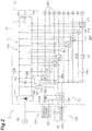
- the motor control device 1 includes a power system circuit 110 and a control system circuit 120.
- the power system circuit 110 is a circuit which generates desired drive power by power conversion, and supplies the drive power to a load.
- Examples of the load include the at least one motor 231.
- the power system circuit 110 can supply the drive power to the nine motors 231 including motors 231A, 231B, 231C, 231D, 231E and 231F of the robot 200.
- the power system circuit 110 includes a rectifier circuit 111, power lines 112A and 112B (first power lines), a capacitor 113, a resistance element 114, a switch 115 and a plurality of (e.g., nine) electronic components 116 (first electronic components).
- the rectifier circuit 111 includes a plurality of rectifier elements (e.g., diodes), and converts power from an alternating-current power source 99 into direct current power.
- the alternating-current power source 99 may be a single phase alternating-current power source or a three-phase alternating-current power source.
- the power lines 112A and 112B lead the direct current power output from the rectifier circuit 111.
- the capacitor 113 is provided between the power lines 112A and 112B, and smooths the voltage between the power lines 112A and 112B.
- a specific example of the capacitor 113 is an electrolytic capacitor.
- the power system circuit 110 may include a plurality of capacitors 113 between the power lines 112A and 112B.
- the resistance element 114 is provided between the power lines 112A and 112B, and consumes regenerative power from the load as thermal energy.
- the switch 115 is provided between one of the power lines 112A and 112B, and the resistance element 114.
- the switch 115 is, for example, a MOSFET (Metal-Oxide-Semiconductor Field-Effect Transistor), and switches between a state where the one line and the resistance element 114 are connected and a state where the one line and the resistance element 114 are not connected. Consequently, the current flow through the resistance element 114 may be limited to certain operating conditions such as when the regenerative power needs to be consumed, for example when the motor suddenly decelerates or suddenly stops.
- MOSFET Metal-Oxide-Semiconductor Field-Effect Transistor
- a plurality of electronic components 116 outputs drive power to a plurality of motors 231, respectively.
- Each electronic component 116 includes a plurality of switching elements 117 such as IGBTs (Insulated Gate Bipolar Transistor) (only one is illustrated in FIG. 2 for ease of illustration), and is provided between the power lines 112A and 112B.
- the electronic component 116 is switched on or off by the switching element 117 to convert the direct current power into alternating-current power between the power lines 112A and 112B and to output the alternating-current power as the drive power to the motor 231.
- the control system circuit 120 is a circuit which controls a plurality of electronic components 116 to output desired drive power to a plurality of motors 231, respectively.
- the control system circuit 120 includes a control power source 121, power lines 122A and 122B (second power lines), an electronic component 123 (a second electronic component) and an electronic component 124 (a third electronic component).
- the control power source 121 converts power from the alternating-current power source 99 into direct current power at the voltage for the control system circuit 120.
- the power lines 122A and 122B lead the direct current power output from the control power source 121.
- the electronic component 123 executes computation processing for controlling the electronic components 116.
- the electronic component 123 is, for example, a processor, and obtains a control target value (a target rotation angle or a target rotation speed) of each motor 231, calculates a torque for making the state of each motor 231 close to the control target value, and outputs the torque as a torque target value to the electronic component 124.
- a control target value a target rotation angle or a target rotation speed
- the electronic component 124 executes computation processing for controlling the electronic components 116 in cooperation with the electronic component 123.
- the electronic component 124 is, for example, a programmable logic array, is interposed between the electronic component 123 and the electronic components 116 and executes processing in response to an input from the electronic component 123. For example, the electronic component 124 outputs an on/off command of the switching element 117 to the electronic component 116 to output drive power corresponding to the torque target value inputted from the electronic component 123 to each motor 231.
- the motor control device 1 includes a board 10 (a first board), boards 20 (a second boards), a board 30 (a third board), a case 40, two blowers 51 and 52 (first blowers) and a blower 53 (second blower).
- the case 40 includes a wall portion (a first wall portion) in which vent holes are formed, and houses the boards 10, 20 and 30.
- the case 40 includes an external shape of a rectangular parallelepiped as illustrated in FIG. 3 , and includes six panels which form six surfaces of the external shape.
- a panel located on a lower side in FIG. 3 is referred to as a bottom panel 41 (a bottom portion) below.
- a panel on a front side in FIG. 3 is referred to as a front panel 42 (a first wall portion).
- a panel on a rear side in FIG. 3 is referred to as a rear panel 43 (a second wall portion).
- a panel located on an upper side in FIG. 3 is referred to as a top panel.
- Panels on left and right sides in FIG. 3 are referred to as side panels.
- the motor control device 1 may be installed in a state where, for example, the bottom panel 41 is vertically installed in a state where, for example, the bottom panel 41 is vertically installed in some cases.
- the two or more panels among the six panels may be integrally formed with each other.
- the bottom panel 41 may be integrally formed with the two side panels.
- a width W of the case 40 is large compared to a depth D of the case 40.
- a height H of the case 40 is small compared to the depth D of the case 40.
- the relationships between the width W, the depth D and the height H are examples, and are not limited to this.
- the front panel 42 includes a plurality of vent holes 44 and a plurality of connectors 45.
- the vent holes 44 penetrate the front panel 42, and enable ventilation between the inside and the outside of the case 40.
- a plurality of connectors 45 is used to connect with each motor 231, to connect with the alternating-current power source 99 and to connect with a host control device (not illustrated).
- the rear panel 43 includes a plurality of vent holes 46.
- the vent holes 46 penetrate the rear panel 43, and enable ventilation between the inside and the outside of the case 40.
- the blowers 51, 52 and 53 generate air currents which pass through the case 40 via the vent holes 44 and 46 in a depth direction of the case.
- the blowers 51, 52 and 53 generate air currents which pass through the case 40 from the front panel 42 to the rear panel 43. That is, the blowers 51, 52 and 53 generate air currents which enter the case 40 from the vent holes 44, and exit from the vent holes 46 to the outside of the case 40.
- the blowers 51, 52 and 53 are fixed to an outer side of the rear panel 43 in a state where the blowers 51, 52 and 53 are aligned in a width direction of the case.
- the blowers 51 and 52 generate air currents which contact a heat radiator 21 described below.
- the blower 53 generates an air current which contacts a heat radiator 35 described below.
- the blowers 51, 52 and 53 may be fixed to the inner side of the rear panel 43, or may be fixed to the outer side or the inner side of the front panel 42.
- the board 10 has, for example, a rectangular shape, is disposed on the bottom panel 41 such that four sides of the board 10 are along the four sides of the bottom panel 41, and is fixed to the bottom panel 41 with a plurality of spacers 13 interposed therebetween.
- the board 10 includes the at least one electronic component 124 (see FIG. 2 ).
- the board 10 includes, for example, a circuit 11 (a first circuit) which is connected to the electronic components 116, a circuit 12 (a second circuit) which is connected to the electronic component 123 and located apart from the circuit 11, and at least one transmission router TR which transmits a signal between the circuit 11 and the circuit 12 in a state where the circuit 11 and the circuit 12 are electrically insulated.
- the circuit 11 includes, for example, the rectifier circuit 111, the power lines 112A and 112B, the capacitor 113 and the switch 115.
- the circuit 12 includes the power lines 122A and 122B and the electronic component 124.
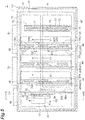
- the circuits 11 and 12 are formed without overlapping each other seen from a direction (an upper side or a lower side in FIG. 3 ) perpendicular to the board 10, and a gap is provided between the circuits 11 and 12 (see FIG. 5 ).
- the at least one transmission router TR includes, for example, transmission routers TR1, TR2 and TR3 illustrated in FIG. 2 .
- the transmission router TR1 transmits an on/off command of the switching element 117 from the electronic component 124 to the electronic component 116 via an insulation type signal transmission element tr1 such as a photocoupler.
- the transmission router TR2 transmits a signal related to a voltage and a current between the power lines 112A and 112B to the electronic component 123 via an insulation type signal transmission element tr2 such as a photocoupler.
- the signal transmitted by the transmission router TR2 is used to detect an abnormality, for example.
- the transmission router TR3 transmits to the electronic component 123 a signal related to an input current from the power lines 112A and 112B to each electronic component 116 via an insulation type signal transmission element tr3 such as a photocoupler.
- the signal transmitted by the transmission router TR3 is used as, for example, a control feedback signal. Furthermore, the signal transmitted by the transmission router TR3 can be also used to detect an abnormality.
- the boards 20 are disposed along a plane P1 intersecting (e.g., perpendicular to) the board 10, and are attached to the board 10.
- the board 30 is disposed along a plane P2 intersecting (e.g., perpendicular to) the board 10, and is attached to the board 10.
- the planes P1 and P2 may be parallel to each other. That is, the boards 20 and 30 are upright with respect to the board 10, and are, in a state of being disposed along the same direction with each other, aligned in a direction perpendicular to this same direction.
- the boards 20 and the board 30 have rectangular shapes that are aligned in a width direction such that the longest side of each board is oriented along the depth direction.
- the rectangular shape is a substantial rectangular shape, and includes a shape which includes a protruding connector and cutouts for wiring cable at a periphery.
- the above parallel state includes a substantially parallel state, and includes a state where there is an inclination of an error level with respect to a strict parallel state.
- the board 20 includes the at least one electronic component 116.
- the board 20 includes, for example, a plurality of electronic components 116, the heat radiator 21 (a first heat radiator), power lines 22A and 22B (third power lines) and a connector 23.
- the electronic component 116 is fixed to a surface 20a of the board 20 that faces away from the board 30.
- the electronic component 116 includes, for example, a package 118 including a plurality of switching elements 117, and a plurality of terminals 119.
- a plurality of terminals 119 is connected to a conductive line (not illustrated) on the surface 20a.
- the electronic component 116 may be fixed to a surface 20b of the board 20 that faces toward the board 30.
- a plurality of electronic components 116 is aligned along a direction intersecting the front panel 42, and is aligned from a windward side to a leeward side of air currents F1 of the above blowers 51 and 52.
- a plurality of electronic components 116 is aligned from the side of the front panel 42 to the side of the rear panel 43 along the depth direction of the case 40.
- a plurality of electronic components 116 includes the at least three electronic components 116.
- the three electronic components 116 are distinguished as an electronic component 116A, an electronic component 116B and an electronic component 116C.
- the electronic components 116A, 116B and 116C are aligned from the side of the front panel 42 to the side of the rear panel 43.
- Upper limits of output power of the plurality of electronic components 116 may be different from each other.
- the upper limits of the output power being different from each other include not only a case where the upper limits of the output power according to a specification of the electronic components 116 (e.g. maximum rated output) are different from each other, but also a case where the upper limits of the output power of software settings for controlling the electronic components 116 by the electronic components 123 and 124 are different from each other.
- the upper limit of the output power of the electronic component 116 located on the closest side to the front panel 42 may be larger than the upper limits of the output power of the other electronic components 116.
- the upper limit of the output power of the electronic component 116A may be larger than the upper limits of the output power of the electronic components 116B and 116C.
- the plurality of electronic components 116 includes two electronic components 116, and an electronic component 116 which is located between the two electronic components 116 and has a smaller upper limit of the output power than those of the two electronic components 116.
- the upper limit of the output power of the electronic component 116B may be smaller than the upper limits of the output power of the electronic components 116A and 116C.
- the arrangement of the plurality of electronic components 116 is not limited to the above exemplified arrangement.
- the upper limit of the output power of the electronic component 116 located closest to the rear panel 43 may be larger than the upper limits of the output power of the other electronic components 116.
- the upper limit of the output power of the electronic component 116C may be larger than the upper limits of the output power of the electronic components 116A and 116B.
- the upper limit of the output power of the electronic component 116 located closest to the front panel 42 may be smaller than the upper limits of the output power of the other electronic components 116.
- the upper limit of the output power of the electronic component 116A may be smaller than the upper limits of the output power of the electronic components 116B and 116C.
- the plurality of electronic components 116 includes the two electronic components 116 which are adjacent at an interval G1 (a first interval), and the two electronic components 116 which are adjacent at an interval G2 (a second interval) shorter than the interval G1.
- the electronic component 116 located closest to the front panel 42 and the second closest electronic component 116 from the side of the front panel 42 may be adjacent at the interval G1
- the other two electronic components 116 than the electronic component 116 located closest to the front panel 42 may be adjacent at the interval G2.
- the board 20 includes the three electronic components 116A, 116B and 116C
- the electronic component 116A and the electronic component 116B may be adjacent at the interval G1
- the electronic component 116B and the electronic component 116C may be adjacent at the interval G2.
- the three electronic components 116 include the two electronic components 116A and 116B which are adjacent at the interval G1, and the two electronic components 116B and 116C which are adjacent at the interval G2.
- the electronic component 116 e.g., electronic component 116C
- the second closest electronic component 116 e.g., electronic component 116B
- the other two electronic components 116 e.g., electronic components 116A and 116B
- the electronic component 116 located closest to the rear panel 43 may be adjacent at the interval G2.
- the power lines 22A and 22B are connected to the power lines 112A and 112B of the board 10, respectively, and are connected to a plurality of electronic components 116 on the board 20. In other words, the power lines 22A and 22B are interposed between the power lines 112A and 112B and a plurality of electronic components 116.
- the power lines 22A and 22B may be wired so as to pass through a region between the two electronic components 116 adjacent at the interval G1.
- the power lines 22A and 22B may be wired between the electronic component 116 located closest to the front panel 42 and the second closest electronic component 116 from the front panel 42.
- the connector 23 is connected to the board 10.
- the connector 23 is provided at a lower portion of the board 20 to connect a conductive line of the board 20 including the power lines 22A and 22B, and a conductive line of the board 10 including the power lines 112A and 112B.
- the connector 23 may be provided, in a direction (a depth direction) in which a plurality of electronic components 116 is aligned, at a position at which at least part of the connector 23 overlaps a region between the two electronic components 116 (e.g., between the electronic component 116A and the electronic component 116B) which are adjacent at the interval G1.
- the heat radiator 21 is in contact with at least two of the electronic components 116 which have different upper limits of output power from each other among a plurality of electronic components 116.
- the heat radiator 21 includes a base 24 and a plurality of heat radiator fins 25.
- the base 24 is fixed to the board 20 with a plurality of spacers 32 interposed therebetween in a state where the base 24 is in contact with the packages 118 of all of the electronic components 116.
- a plurality of heat radiator fins 25 is aligned in a height direction, and protrudes from the base 24 toward the opposite side of the packages 118 in a state where the plurality of heat radiator fins 25 is aligned along the depth direction. Consequently, the air currents F1 of the blowers 51 and 52 can pass between the heat radiator fins 25 along the depth direction.
- a material of the heat radiator 21 includes an aluminum-based or copper-based metal material.
- a plurality of electronic components 116 and the heat radiator 21 may be unevenly disposed on the board 20 in a direction apart from the board 10. That is, the electronic components 116 and the heat radiator 21 may be unevenly disposed on an upper side of the board 20.
- the capacitor 113 of the board 10 may be disposed at a position at which the capacitor 113 overlaps the heat radiator 21 seen from a direction perpendicular to the board 10. That is, the capacitor 113 may be located below the heat radiator 21.
- a plurality of boards 20 may be attachable to the board 10.
- the three boards 20 aligned in the width direction are attachable to the board 10. That is, the board 10 may include slots to which the boards 20 are attached at three portions aligned in the width direction.
- three boards 20A, 20B and 20C are attached to the board 10, and each of the boards 20A, 20B and 20C includes the three electronic components 116.
- the power system circuit 110 including nine electronic components 116 is formed.
- the motor control device 1 when the control target of the motor control device 1 is only the robot 200, the motor control device 1 only needs to include two of the boards 20A, 20B and 20C (e.g., the boards 20A and 20B). An association between the six electronic components 116 of the boards 20A and 20B and the six motors 231 of the robot 200 will be described below.
- the electronic component 116 located closest to the front panel 42 of each one of the board 20A and the board 20B may be associated with the movable portion 220 that is closer to the side of the base portion 201 than the movable portions 220 associated with the other electronic components 116.
- the association with the movable portion 220 means connection with the motor 231 of the actuator 230 which drives the movable portion 220.
- the electronic component 116A of the board 20A is allocated to the movable portion 220A located closest to the base portion 201 among a plurality of movable portions 220.
- the electronic component 116A of the board 20B is allocated to the movable portion 220B located second closest from the base portion 201 among the plurality of movable portions 220.
- the electronic component 116 located between the two electronic components 116 of at least one of the boards 20A and 20B may be associated with the movable portion 220 closer to the distal end portion 202 than the movable portions 220 associated with the two electronic components 116 located on the both sides.
- the electronic component 116A of the board 20A is allocated to the movable portion 220A located closest to the base portion 201 among a plurality of movable portions 220.
- the electronic component 116C of the board 20A is allocated to the movable portion 220D located in fourth closest from the base portion 201 among a plurality of movable portions 220.
- the electronic component 116B of the board 20A is allocated to the movable portion 220F located closest to the distal end portion 202 among a plurality of movable portions 220.
- the electronic component 116A of the board 20B is allocated to the movable portion 220B located second closest from the base portion 201 among a plurality of movable portions 220.
- the electronic component 116C of the board 20B is allocated to the movable portion 220C located third closest from the base portion 201 among a plurality of movable portions 220.
- the electronic component 116B of the board 20B is allocated to the movable portion 220E located fifth closest from the base portion 201 (or second closest from the distal end portion 202) among a plurality of movable portions 220.
- the blowers 51 and 52 are disposed such that the air currents F1 are in contact with the heat radiator 21 of each board 20. That is, the blowers 51 and 52 are disposed to generate the air currents F1 at positions in contact with the heat radiator 21.
- the blowers 51 and 52 are disposed such that at least part of each heat radiator 21 overlaps one of the blowers 51 and 52 seen from the direction perpendicular to the front panel 42.
- the board 10 may include a plurality of capacitors 113, and a plurality of capacitors 113 may be disposed in a dispersed manner below the heat radiators 21 of a plurality of boards 20.
- the plurality of capacitors 113 may be disposed below the one heat radiator 21, the plurality of capacitors 113 may be disposed to align along the depth direction.
- the board 30 includes the at least one electronic component 123.
- the board 30 includes the one electronic component 123, a connector 34 and the heat radiator 35 (a second heat radiator).
- the electronic component 123 is fixed to a surface 30a of the board 30 which faces away from the board 20.
- the electronic component 123 is fixed to the surface 30a with a processor board 31 interposed therebetween. That is, the electronic component 123 is fixed to the processor board 31, and the processor board 31 is fixed to the surface 30a with a plurality of spacers 32 interposed therebetween in a state where the electronic component 123 is disposed on an opposite side of the board 30.
- the electronic component 123 may be fixed to a surface 30b which faces toward the board 20 of both surfaces of the board 30.
- the connector 34 is connected to the board 10.
- the connector 34 is provided at a lower portion of the board 30 to connect a conductive line of the board 30 and the conductive line of the board 10 including the power lines 122A and 122B.
- the heat radiator 35 is in contact with the electronic component 123.
- the heat radiator 35 includes a base 36 and a plurality of heat radiator fins 37.
- the base 36 is, for example, a flat body and is in contact with the electronic component 123 in a state where the base 36 is parallel to the board 30.
- the base 36 is fixed to the processor board 31 with a plurality of spacers 33 interposed therebetween.
- a plurality of heat radiator fins 37 is aligned in the height direction, and protrudes from the base 36 toward the opposite side of the electronic component 123 in a state where the plurality of heat radiator fins 37 is aligned along the depth direction. Consequently, an air current F2 of the blower 53 can pass between the heat radiator fins 37 along the depth direction.
- a material of the heat radiator 35 includes an aluminum-based or copper-based metal material.
- the blower 53 is disposed such that the air current F2 is in contact with the heat radiator 35. That is, the blower 53 is disposed to generate the air current F2 at a position at which the blower 53 is in contact with the heat radiator 35. For example, the blower 53 is disposed such that at least part of the heat radiator 35 overlaps the blower 53 seen from the direction perpendicular to the front panel 42.
- vent holes 44A are located at positions at which the vent holes 44 overlap the electronic component 123 in the width direction and are located below the electronic component 123 as illustrated in FIG. 6 .
- the motor control device 1 may further include an air guide member 60.
- the air guide member 60 is configured to guide the air current F2 having entered the case 40 from the vent holes 44A toward the electronic component 123.
- the electronic component 123 and the air guide member 60 may be disposed at different positions when seen from the direction perpendicular to the front panel 42.
- the air guide member 60 includes an inclined surface 60a which is provided on a route of the air current F2 below the electronic component 123, and guides the air current F2 toward the electronic component 123.
- the inclined surface 60a faces an oblique upper side on the side of the front panel 42.
- the air guide member 60 may be fixed to the board 30.
- the air guide member 60 includes a wave guide plate 61 and a connection plate 62.
- the connection plate 62 is fixed to the surface 30a of the board 30.
- the wave guide plate 61 protrudes from the connection plate 62 to the opposite side of the board 30 such that one surface forms the inclined surface 60a.
- the heat radiator 35 may protrude at different lengths from the rim of the electronic component 123 toward the air guide member 60 and toward the opposite side of the air guide member 60 when seen from the direction perpendicular to the front panel 42.
- a protrusion length of the heat radiator 35 from the rim of the electronic component 123 toward the air guide member 60 when seen from the direction perpendicular to the front panel 42 (referred to as a “protrusion length L1" below) may be longer than a protrusion length of the heat radiator 35 from the rim of the electronic component 123 toward the opposite side of the air guide member 60 (referred to as a "protrusion length L2" below).
- the protrusion length of the heat radiator 35 from a lower rim 123b of the electronic component 123 toward a lower side corresponds to the protrusion length L1
- the protrusion length of the heat radiator 35 from an upper rim 123a of the electronic component 123 toward an upper side corresponds to the protrusion length L2 (see FIG. 4 ).
- the base 36 of the heat radiator 35 may protrude from a rim 37a of the heat radiator fin 37 on a side of the front panel 42 toward the front panel 42.
- an upper portion 36a of the base 36 may protrude further toward the front panel 42 as compared to a lower portion 36b of the base 36.
- the heat radiator 35 includes a first portion 35a which is at least partially in contact with the electronic component 123 and includes a plurality of heat radiator fins 37 protruding toward the opposite side of the electronic component 123, a second portion 35b which protrudes from the first portion 35a toward the air guide member 60 in a direction along the front panel 42 and includes a plurality of heat radiator fin 37, and a third portion 35c which protrudes from the first portion 35a toward the front panel 42 and does not include the heat radiator fin 37.
- the motor control device 1 may further include an electronic component 70 (a fourth electronic component).
- the electronic component 70 includes a main body 71, a cover 72 (a first cover), a cover 73 (a second cover), a ventilation route 74 and a plurality of spacers 75.
- the main body 71 includes a passive circuit element.
- the passive circuit element of the main body 71 may be any circuit element as long as the circuit element is necessary for the configuration of the motor control device 1.
- the passive circuit element of the main body 71 may include, for example, the above resistance element 114.
- the resistance element 114 may be formed by a cement resistor.
- the main body 71 may have, for example, an external shape of a rectangular flat shape.
- the cover 72 covers at least part of the main body 71 and is heated by heat generated by the main body 71.
- the cover 72 may have conductivity and have higher thermal conductivity than the cover 73.
- the cover 72 is formed by an aluminum-based metal plate.
- the cover 72 includes a tubular part 72a which surrounds the main body 71 about an axis line along a longitudinal direction of the main body 71. Both end portions of the tubular part 72a are opened.
- the cover 73 has an electrical insulation property, and covers the cover 72 from the opposite side of the main body 71.
- the cover 73 is formed by a rubber material or a resin material, and closely adheres to the cover 72.
- the cover 73 may cover the entire circumference of the tubular part 72a.
- the ventilation route 74 is formed between the cover 72 and the main body 71.
- the cover 72 faces the main body 71 with a gap interposed therebetween, and the gap may form the ventilation route 74.
- the entire circumference of the tubular part 72a of the cover 72 may face the entire circumference of the main body 71 with a gap interposed therebetween. In this case, the ventilation route 74 which passes from one end side to the other end side of the tubular part 72a is formed.
- the cover 72 which faces the main body 71 with the gap interposed therebetween as described above is fixed to the main body 71 with a plurality of spacers 75 interposed therebetween.
- the spacers 75 are interposed between the cover 72 and the main body 71, and are configured to transfer heat from the main body 71 to the cover 72.
- the electronic component 70 is connected with one of the boards 10, 20 and 30.
- the circuit element of the main body 71 is connected to the board 10.
- the main body 71 includes the resistance element 114
- the main body 71 is connected to the power lines 112A and 112B with the switch 115 interposed therebetween.
- the electronic component 70 is fixed to the case 40 in a state where the ventilation route 74 is oriented along the depth direction (a state where the longitudinal direction of the main body 71 is along the depth direction).
- the electronic component 70 is disposed at a position at which the board 20 is sandwiched between the board 30 and the electronic component 70 such that the main body 71 is parallel to the board 20 and the board 30.
- the blowers 51 and 52 may be disposed such that the air currents F1 pass the ventilation route 74.
- the blower 51 may be disposed such that at least part of the blower 51 overlaps the ventilation route 74 when seen from the direction perpendicular to the front panel 42.
- the motor control device 1 includes the board 10, the board 20 which includes the electronic components 116 for power conversion, is disposed along the plane P1 intersecting the board 10, and is attached to the board 10, and the board 30 which includes the electronic component 123 which executes computation processing for controlling the electronic components 116, is disposed along the plane P2 intersecting the board 10, and is attached to the board 10.
- the electronic components 116 and the electronic component 123 are dispersed on the two boards 20 and 30 which intersect the board 10. Consequently, the area of the board 10 can be reduced, and most of a space adjacent to the board 10 can be effectively used for an arrangement of the electronic components 116 and the electronic component 123. Consequently, the motor control device 1 is effective for space saving.
- the board 10 may include the electronic component 124 which executes computation processing for controlling the electronic components 116 in cooperation with the electronic component 123.
- the electronic component 124 which executes computation processing for controlling the electronic components 116 in cooperation with the electronic component 123.
- the board 10 may include the electronic component 124 which executes computation processing for controlling the electronic components 116 in cooperation with the electronic component 123.
- the electronic component 124 may be interposed between the electronic component 123 and the electronic components 116, and may be configured to execute computation processing in response to the input from the electronic component 123.
- the electronic component 124 interposed between the electronic component 123 and the electronic components 116 is disposed on the first board interposed between the second board and the third board in order to simplify the wiring.
- the board 10 may include the circuit 11 which is connected to the electronic components 116, the circuit 12 which is connected to the electronic component 123 and located apart from the circuit 11, and the transmission router TR which transmits a signal between the circuit 11 and the circuit 12 in a state where the circuit 11 and the circuit 12 are electrically insulated.
- the transmission router TR which transmits a signal between the circuit 11 and the circuit 12 in a state where the circuit 11 and the circuit 12 are electrically insulated.
- the board 20 may include a plurality of electronic components 116 which includes the electronic components 116 and the another electronic components 116 having a different upper limit of output value from those of the electronic components 116, and the at least one heat radiator 21, and the heat radiator 21 may be in contact with at least two of the electronic components 116 which have at least different upper limits of output power from each other among the plurality of electronic components 116.
- a portion of the heat radiator 21 which is in contact with the electronic component 116 having a smaller heat generation amount can be used for heat radiation of the electronic component 116 having a larger heat generation amount.
- a portion of the heat radiator 21 located between the electronic components 116 can be used for heat radiation. Consequently, both space savings and efficient cooling can be achieved.
- the motor control device 1 may further include the case 40 which includes the front panel 42 in which the vent holes 44 are formed, and houses the boards 10, 20 and 30, and the blowers 51 and 52 which generate the air currents F1 which enter from the vent holes 44 into the case 40, and a plurality of electronic components 116 may be aligned along the direction intersecting the front panel 42.
- the air current F1 having passed the electronic component 116 on the windward side can be also used to cool the electronic component 116 on the leeward side. Consequently, both space savings and efficient cooling can be reliably achieved.
- the upper limit of the output power of the electronic component 116 located closest to the front panel 42 among a plurality of electronic components 116 may be larger than the upper limits of the output power of the other electronic components 116.
- a cooling efficiency of the plurality of electronic components 116 can be enhanced.
- the plurality of electronic components 116 may include the two electronic components 116, and the electronic component 116 which is located between the two electronic components 116 and has a smaller upper limit of the output power than those of the two electronic components 116. In this case, by separating the electronic components 116 of which heat generation amounts are likely to be large among a plurality of electronic components 116 and enhancing the cooling efficiency of each of the electronic components 116, the cooling efficiency of the plurality of electronic components 116 can be enhanced.
- the plurality of electronic components 116 may include two electronic components 116 adjacent at the interval G1, and two electronic components 116 adjacent at the shorter interval G2 than the interval G1. In this case, by adjusting the interval(s) between the electronic components 116 to suppress heat transfer between the electronic components 116, the cooling efficiency of each electronic component 116 can be enhanced.
- the board 20 may further include the power lines 22A and 22B which are wired so as to pass through a region between the two electronic components 116 adjacent at the interval G1 and are connected to a plurality of electronic components 116. In this case, by utilizing the region between the two electronic components adjacent at the interval G1 larger than the interval G2 for wiring of the power lines 22A and 22B , further space can be saved.
- the board 20 may include the connector 23 which is connected to the board 10, and the connector 23 may be provided, in a flow direction of the air currents F1 of the blowers 51 and 52, at a position at which at least part of the connector 23 overlaps a region between the two electronic components 116 adjacent at the interval G1.
- the power lines 22A and 22B which pass between the two electronic components 116 adjacent at the interval G1 can be wired to the connector 23 via a short route. Consequently, this is more effective for space saving.
- the motor control device 1 may further include the electronic component 70.
- the main body 71 includes the main body 71 which includes the passive circuit element, the cover 72 which covers at least part of the main body 71 and is heated by heat generated by the main body 71, the cover 73 which has an electrical insulation property, and covers the cover 72 from the opposite side of the main body 71, and the ventilation route 74 which is formed between the cover 72 and the main body 71.
- the insulating cover 73 covers the cover 72 from the opposite side of the main body 71, so that a distance between another element located on the side of the cover 72 (e.g., board 20) and the electronic component 70 can be reduced.
- the ventilation route 74 is secured between the cover 72 and the main body 71, so that heat radiation from both of the surface of the main body 71 on the side of the cover 72 and a surface of the cover 72 on the side of the main body 71 can suppress a rise in a temperature of the main body 71. Consequently, the space can be saved while suppressing the rise in the temperature of the main body 71.
- the electronic component 70 may further include the spacers 75 which are interposed between the cover 72 and the main body 71 and conduct heat from the main body 71 to the cover 72. In this case, the rise in the temperature of the main body 71 can be further suppressed.
- the cover 72 includes the tubular part 72a which surrounds the main body 71 about the axis line along the ventilation route 74.
- the tubular part 72a surrounds the main body 71, so that heat transfer efficiency from the main body 71 to the cover 72 and heat radiation efficiency from the cover 72 improve. Consequently, the rise in the temperature of the main body 71 can be further suppressed.
- the cover 72 may have higher thermal conductivity than the cover 73. In this case, the heat transfer efficiency from the main body 71 to the cover 72 and the heat radiation efficiency from the cover 72 improve. Consequently, the rise in the temperature of the main body 71 can be further suppressed.
- the passive circuit element of the main body 71 may include the cement resistor. In this case, by using a general-purpose circuit element, space may be saved while suppressing a rise in cost.
- the motor control device 1 may further include the case 40 which includes the front panel 42 in which the vent holes 44A are formed, and houses the boards 10, 20 and 30; the blower 53 which generates the air current F2 entering from the vent holes 44A into the case 40; and the air guide member 60 which guides the air current F2 having entered the case 40 via the vent hole 44A toward the electronic component 123.
- the case 40 which includes the front panel 42 in which the vent holes 44A are formed, and houses the boards 10, 20 and 30
- the blower 53 which generates the air current F2 entering from the vent holes 44A into the case 40
- the air guide member 60 which guides the air current F2 having entered the case 40 via the vent hole 44A toward the electronic component 123.
- the board 30 may further include the heat radiator 35 which is in contact with the electronic component 123, the electronic component 123 and the air guide member 60 may be disposed at different positions when seen from the direction perpendicular to the front panel 42, and the heat radiator 35 may protrude at different lengths from the rim of the electronic component 123 toward the air guide member 60 and toward the opposite side of the air guide member 60.
- both of the air current which is directed away from the electronic component 123 toward the air guide member 60 (referred to as an "air current A” below) and an air current which is directed away from the electronic component 123 toward the opposite side of the air guide member 60 (referred to as an "air current B” below) when seen from the direction perpendicular to the front panel 42 can be effectively used to cool the electronic component 123.
- An air flow of the air current A and an air flow of the air current B are assumed to differ.
- the heat radiator 35 protrudes at the different lengths from the rim of the electronic component 123 toward the air guide member 60 and toward the opposite side of the air guide member 60 when seen from the direction perpendicular to the front panel 42, the air currents A and B can be effectively used to further cool the electronic component 123.
- the heat radiator 35 may include the base 36 which is in contact with the electronic component 123, and a plurality of heat radiator fins 37 which protrudes from the base 36, and the base 36 may protrude from the rims of the heat radiator fins 37 on the side of the front panel 42 toward the front panel 42.
- the heat radiator fins 37 can be prevented from blocking the air currents guided by the air guide member 60 toward the electronic component 123, and improve heat radiation efficiency of the heat radiator 35.
- the electronic component 116 located on the windward-most side of the air currents F1 of the blowers 51 and 52 may be associated with the movable portion 220 that is closer to the base portion 201 than the movable portions 220 associated with the other electronic components 116.
- a cooling efficiency of the plurality of electronic components 116 can be enhanced.
- the electronic component 116 may be provided on the surface 20a of the board 20 facing away from the board 30, and the electronic component 123 may be provided on the surface 30a of the board 30 facing away from the board 20 among the both surfaces of the board 30.
- the electronic components 116 and 123 are partitioned by the boards 20 and 30. Consequently, heat transfer between the electronic components 116 and 123 can be suppressed, and the cooling efficiency of the electronic components 116 and 123 can be further enhanced.
- a plurality of electronic components 116 and the heat radiator 21 may be unevenly disposed on the board 20 in a direction apart from the board 10. In this case, heat transfer from the electronic components 116 to the electronic components disposed on the board 10 is suppressed. Consequently, a stability of operations of the electronic components disposed on the board 10 may be further enhanced.
- the capacitor 113 of the board 10 may be disposed at a position in which the capacitor 113 overlaps the heat radiator 21 when seen from the direction perpendicular to the board 10. In this case, the space between the heat radiator 21 and the board 10 can be effectively used for the arrangement of the capacitor 113. Consequently, space can be further saved.
- air currents F1 for cooling the heat radiator 21 can also be used to cool the capacitor 113.
- a ventilation resistance between the heat radiator 21 and the board 10 can be enhanced, and the air flow of the air current F1 on the side of the heat radiator 21 can be increased. Consequently, it is possible to further enhance the cooling efficiency of the electronic components 116.
- the enhanced cooling efficiency of the electronic components 116 contributes to suppression of heat transfer from the electronic components 116 to the capacitor 113, and contributes to improvement of durability of the capacitor 113, too.
- a control target of the motor control device 1 is not limited to robots.
- the motor control device 1 is applicable to control of any devices as long as the devices need motor control.
- the present disclosure can be used for a motor control device which controls a motor.
Landscapes
- Engineering & Computer Science (AREA)
- Power Engineering (AREA)
- Microelectronics & Electronic Packaging (AREA)
- Physics & Mathematics (AREA)
- Thermal Sciences (AREA)
- Robotics (AREA)
- Mechanical Engineering (AREA)
- Automation & Control Theory (AREA)
- Inverter Devices (AREA)
- Cooling Or The Like Of Electrical Apparatus (AREA)
- Control Of Ac Motors In General (AREA)
Abstract
Description
- The present disclosure relates to a motor control device and a robot system.
-
Patent Literature 1 discloses a mounting method for vertically installing a sub-circuit board including a motor drive circuit mounted thereon, on a main circuit board including a control circuit mounted thereon. - Patent Literature 1: Japanese Unexamined Patent Publication No.
2007-281347 - An object of the present disclosure is to provide a motor control device and a robot system which are effective to save a space.
- A motor control device according to one aspect of the present disclosure includes: a first board; a second board including a first electronic component including a switching element for power conversion, disposed along a plane intersecting the first board, and attached to the first board; and a third board including a second electronic component configured to execute computation processing for controlling the first electronic component, disposed along a plane intersecting the first board, and attached to the first board.
- A robot system according to one aspect of the present disclosure includes: a robot including at least one actuator; and a motor control device configured to control the actuator, and the motor control device includes a first board, a second board including a first electronic component including a switching element for power conversion, disposed along a plane intersecting the first board, and attached to the first board, and a third board including a second electronic component configured to execute computation processing for controlling the first electronic component, disposed along a plane intersecting the first board, and attached to the first board.
- The present disclosure can provide a motor control device and a robot system which are effective to save a space.
-
-
FIG. 1 is a schematic view illustrating a configuration of a robot system. -
FIG. 2 is a schematic view illustrating a circuit configuration of a motor control device. -
FIG. 3 is a perspective view illustrating a motor control device. -
FIG. 4 is a cross-sectional view taken along a IV-IV line inFIG. 3 . -
FIG. 5 is a cross-sectional view taken along a V-V line inFIG. 4 . -
FIG. 6 is a cross-sectional view taken along a VI-VI line inFIG. 5 . - Hereinafter, an embodiment will be described in detail with reference to the drawings. The same components or components having the same function will be assigned the same reference numerals in the following description, and overlapping description is omitted.
- As illustrated in
FIG. 1 , a robot system S1 according to the present embodiment includes arobot 200 and amotor control device 1. Therobot 200 includes at least oneactuator 230. Themotor control device 1 controls theactuator 230 of therobot 200. Specific configurations of therobot 200 and themotor control device 1 will be described below. - The
robot 200 includes abase portion 201, a distal end portion 202, anarm portion 210, a plurality ofmovable portions 220 and a plurality ofactuators 230. Thearm portion 210 joints thebase portion 201 and the distal end portion 202. A plurality ofmovable portions 220 is aligned along thearm portion 210. - The
arm portion 210 includes, for example, aturning portion 211 which is provided on thebase portion 201, afirst arm portion 212 which is connected to theturning portion 211, asecond arm portion 213 which is connected to a distal end portion (an end portion on an opposite side of the base portion 201) of thefirst arm portion 212, and athird arm portion 216 which is connected to a distal end portion of thesecond arm portion 213. - A plurality of
movable portions 220 includes sixmovable portions movable portion 220A makes theturning portion 211 turnable about a vertical axis line passing through thebase portion 201. Themovable portion 220B makes thefirst arm portion 212 swingable about an axis line passing through a connection portion of theturning portion 211 and thefirst arm portion 212. Themovable portion 220C makes thesecond arm portion 213 swingable about an axis line passing through a connection portion of thefirst arm portion 212 and thesecond arm portion 213. Themovable portion 220D makes adistal end portion 215 of thesecond arm portion 213 turnable about an axis aligned along thesecond arm portion 213. Themovable portion 220E makes thethird arm portion 216 swingable about an axis line passing through a connection portion of thesecond arm portion 213 and thethird arm portion 216. Themovable portion 220F makes the distal end portion 202 turnable about an axis aligned along thethird arm portion 216. In addition, the number of themovable portions 220 may be six or more (e.g., seven) or may be smaller than six (e.g., four). - A plurality of
actuators 230 drives a plurality ofmovable portions 220, respectively, to displace thedistal end portion 215. A plurality ofactuators 230 includes, for example, sixactuators movable portions - In addition, driving the
movable portion 220 means moving a portion which is made movable by themovable portion 220. For example, driving themovable portion 220A means turning theturning portion 211 which is made movable by themovable portion 220A. - Each of a plurality of
actuators 230 includes an electrically poweredmotor 231 as a power source. A specific example of themotor 231 is an alternating-current motor such as a three-phase alternating-current motor. - First, a circuit configuration of the
motor control device 1 will be described. Themotor control device 1 includes apower system circuit 110 and acontrol system circuit 120. - The
power system circuit 110 is a circuit which generates desired drive power by power conversion, and supplies the drive power to a load. Examples of the load include the at least onemotor 231. For example, thepower system circuit 110 can supply the drive power to the ninemotors 231 including motors 231A, 231B, 231C, 231D, 231E and 231F of therobot 200. - More specifically, the
power system circuit 110 includes arectifier circuit 111,power lines capacitor 113, aresistance element 114, aswitch 115 and a plurality of (e.g., nine) electronic components 116 (first electronic components). - The
rectifier circuit 111 includes a plurality of rectifier elements (e.g., diodes), and converts power from an alternating-current power source 99 into direct current power. The alternating-current power source 99 may be a single phase alternating-current power source or a three-phase alternating-current power source. Thepower lines rectifier circuit 111. Thecapacitor 113 is provided between thepower lines power lines capacitor 113 is an electrolytic capacitor. Thepower system circuit 110 may include a plurality ofcapacitors 113 between thepower lines - The
resistance element 114 is provided between thepower lines switch 115 is provided between one of thepower lines resistance element 114. Theswitch 115 is, for example, a MOSFET (Metal-Oxide-Semiconductor Field-Effect Transistor), and switches between a state where the one line and theresistance element 114 are connected and a state where the one line and theresistance element 114 are not connected. Consequently, the current flow through theresistance element 114 may be limited to certain operating conditions such as when the regenerative power needs to be consumed, for example when the motor suddenly decelerates or suddenly stops. - A plurality of
electronic components 116 outputs drive power to a plurality ofmotors 231, respectively. Eachelectronic component 116 includes a plurality of switchingelements 117 such as IGBTs (Insulated Gate Bipolar Transistor) (only one is illustrated inFIG. 2 for ease of illustration), and is provided between thepower lines electronic component 116 is switched on or off by the switchingelement 117 to convert the direct current power into alternating-current power between thepower lines motor 231. - The
control system circuit 120 is a circuit which controls a plurality ofelectronic components 116 to output desired drive power to a plurality ofmotors 231, respectively. Thecontrol system circuit 120 includes acontrol power source 121,power lines - The
control power source 121 converts power from the alternating-current power source 99 into direct current power at the voltage for thecontrol system circuit 120. Thepower lines control power source 121. - The
electronic component 123 executes computation processing for controlling theelectronic components 116. Theelectronic component 123 is, for example, a processor, and obtains a control target value (a target rotation angle or a target rotation speed) of eachmotor 231, calculates a torque for making the state of eachmotor 231 close to the control target value, and outputs the torque as a torque target value to theelectronic component 124. - The
electronic component 124 executes computation processing for controlling theelectronic components 116 in cooperation with theelectronic component 123. Theelectronic component 124 is, for example, a programmable logic array, is interposed between theelectronic component 123 and theelectronic components 116 and executes processing in response to an input from theelectronic component 123. For example, theelectronic component 124 outputs an on/off command of theswitching element 117 to theelectronic component 116 to output drive power corresponding to the torque target value inputted from theelectronic component 123 to eachmotor 231. - Next, a mechanical structure of the
motor control device 1 will be described. As illustrated inFIGS. 3 to 5 , themotor control device 1 includes a board 10 (a first board), boards 20 (a second boards), a board 30 (a third board), acase 40, twoblowers 51 and 52 (first blowers) and a blower 53 (second blower). - The
case 40 includes a wall portion (a first wall portion) in which vent holes are formed, and houses theboards case 40 includes an external shape of a rectangular parallelepiped as illustrated inFIG. 3 , and includes six panels which form six surfaces of the external shape. A panel located on a lower side inFIG. 3 is referred to as a bottom panel 41 (a bottom portion) below. A panel on a front side inFIG. 3 is referred to as a front panel 42 (a first wall portion). A panel on a rear side inFIG. 3 is referred to as a rear panel 43 (a second wall portion). A panel located on an upper side inFIG. 3 is referred to as a top panel. Panels on left and right sides inFIG. 3 are referred to as side panels. Furthermore, "upper and lower sides", the "width", the "depth" and the "height" mean the "upper and lower sides", the "width", the "depth" and the "height" of an arrangement inFIG. 3 . In addition to the illustrated state, themotor control device 1 may be installed in a state where, for example, thebottom panel 41 is vertically installed in a state where, for example, thebottom panel 41 is vertically installed in some cases. The two or more panels among the six panels may be integrally formed with each other. For example, thebottom panel 41 may be integrally formed with the two side panels. - A width W of the
case 40 is large compared to a depth D of thecase 40. A height H of thecase 40 is small compared to the depth D of thecase 40. The relationships between the width W, the depth D and the height H are examples, and are not limited to this. - The
front panel 42 includes a plurality of vent holes 44 and a plurality ofconnectors 45. The vent holes 44 penetrate thefront panel 42, and enable ventilation between the inside and the outside of thecase 40. A plurality ofconnectors 45 is used to connect with eachmotor 231, to connect with the alternating-current power source 99 and to connect with a host control device (not illustrated). - The
rear panel 43 includes a plurality of vent holes 46. The vent holes 46 penetrate therear panel 43, and enable ventilation between the inside and the outside of thecase 40. - The
blowers case 40 via the vent holes 44 and 46 in a depth direction of the case. For example, theblowers case 40 from thefront panel 42 to therear panel 43. That is, theblowers case 40 from the vent holes 44, and exit from the vent holes 46 to the outside of thecase 40. - For example, the
blowers rear panel 43 in a state where theblowers blowers heat radiator 21 described below. Theblower 53 generates an air current which contacts aheat radiator 35 described below. In addition, theblowers rear panel 43, or may be fixed to the outer side or the inner side of thefront panel 42. - As illustrated in
FIGS. 4 and5 , theboard 10 has, for example, a rectangular shape, is disposed on thebottom panel 41 such that four sides of theboard 10 are along the four sides of thebottom panel 41, and is fixed to thebottom panel 41 with a plurality ofspacers 13 interposed therebetween. - The
board 10 includes the at least one electronic component 124 (seeFIG. 2 ). Theboard 10 includes, for example, a circuit 11 (a first circuit) which is connected to theelectronic components 116, a circuit 12 (a second circuit) which is connected to theelectronic component 123 and located apart from thecircuit 11, and at least one transmission router TR which transmits a signal between thecircuit 11 and thecircuit 12 in a state where thecircuit 11 and thecircuit 12 are electrically insulated. - The
circuit 11 includes, for example, therectifier circuit 111, thepower lines capacitor 113 and theswitch 115. Thecircuit 12 includes thepower lines electronic component 124. Thecircuits FIG. 3 ) perpendicular to theboard 10, and a gap is provided between thecircuits 11 and 12 (seeFIG. 5 ). - The at least one transmission router TR includes, for example, transmission routers TR1, TR2 and TR3 illustrated in
FIG. 2 . The transmission router TR1 transmits an on/off command of theswitching element 117 from theelectronic component 124 to theelectronic component 116 via an insulation type signal transmission element tr1 such as a photocoupler. - The transmission router TR2 transmits a signal related to a voltage and a current between the
power lines electronic component 123 via an insulation type signal transmission element tr2 such as a photocoupler. The signal transmitted by the transmission router TR2 is used to detect an abnormality, for example. - The transmission router TR3 transmits to the
electronic component 123 a signal related to an input current from thepower lines electronic component 116 via an insulation type signal transmission element tr3 such as a photocoupler. The signal transmitted by the transmission router TR3 is used as, for example, a control feedback signal. Furthermore, the signal transmitted by the transmission router TR3 can be also used to detect an abnormality. - The
boards 20 are disposed along a plane P1 intersecting (e.g., perpendicular to) theboard 10, and are attached to theboard 10. Theboard 30 is disposed along a plane P2 intersecting (e.g., perpendicular to) theboard 10, and is attached to theboard 10. The planes P1 and P2 may be parallel to each other. That is, theboards board 10, and are, in a state of being disposed along the same direction with each other, aligned in a direction perpendicular to this same direction. For example, theboards 20 and theboard 30 have rectangular shapes that are aligned in a width direction such that the longest side of each board is oriented along the depth direction. In addition, the rectangular shape is a substantial rectangular shape, and includes a shape which includes a protruding connector and cutouts for wiring cable at a periphery. In addition, the above parallel state includes a substantially parallel state, and includes a state where there is an inclination of an error level with respect to a strict parallel state. - The
board 20 includes the at least oneelectronic component 116. Theboard 20 includes, for example, a plurality ofelectronic components 116, the heat radiator 21 (a first heat radiator),power lines connector 23. - The
electronic component 116 is fixed to asurface 20a of theboard 20 that faces away from theboard 30. Theelectronic component 116 includes, for example, apackage 118 including a plurality of switchingelements 117, and a plurality ofterminals 119. A plurality ofterminals 119 is connected to a conductive line (not illustrated) on thesurface 20a. In addition, theelectronic component 116 may be fixed to asurface 20b of theboard 20 that faces toward theboard 30. - A plurality of
electronic components 116 is aligned along a direction intersecting thefront panel 42, and is aligned from a windward side to a leeward side of air currents F1 of theabove blowers electronic components 116 is aligned from the side of thefront panel 42 to the side of therear panel 43 along the depth direction of thecase 40. A plurality ofelectronic components 116 includes the at least threeelectronic components 116. Hereinafter, as appropriate, the threeelectronic components 116 are distinguished as anelectronic component 116A, anelectronic component 116B and an electronic component 116C. Theelectronic components front panel 42 to the side of therear panel 43. - Upper limits of output power of the plurality of
electronic components 116 may be different from each other. In this regard, the upper limits of the output power being different from each other include not only a case where the upper limits of the output power according to a specification of the electronic components 116 (e.g. maximum rated output) are different from each other, but also a case where the upper limits of the output power of software settings for controlling theelectronic components 116 by theelectronic components - For example, the upper limit of the output power of the
electronic component 116 located on the closest side to thefront panel 42 may be larger than the upper limits of the output power of the otherelectronic components 116. When theboard 20 includes the threeelectronic components electronic component 116A may be larger than the upper limits of the output power of theelectronic components 116B and 116C. - Furthermore, the plurality of
electronic components 116 includes twoelectronic components 116, and anelectronic component 116 which is located between the twoelectronic components 116 and has a smaller upper limit of the output power than those of the twoelectronic components 116. When theboard 20 includes the threeelectronic components electronic component 116B may be smaller than the upper limits of the output power of theelectronic components 116A and 116C. - The arrangement of the plurality of
electronic components 116 is not limited to the above exemplified arrangement. For example, the upper limit of the output power of theelectronic component 116 located closest to therear panel 43 may be larger than the upper limits of the output power of the otherelectronic components 116. When theboard 20 includes the threeelectronic components electronic components - Furthermore, the upper limit of the output power of the
electronic component 116 located closest to thefront panel 42 may be smaller than the upper limits of the output power of the otherelectronic components 116. When theboard 20 includes the threeelectronic components electronic component 116A may be smaller than the upper limits of the output power of theelectronic components 116B and 116C. - The plurality of
electronic components 116 includes the twoelectronic components 116 which are adjacent at an interval G1 (a first interval), and the twoelectronic components 116 which are adjacent at an interval G2 (a second interval) shorter than the interval G1. For example, theelectronic component 116 located closest to thefront panel 42 and the second closestelectronic component 116 from the side of thefront panel 42 may be adjacent at the interval G1, whereas the other twoelectronic components 116 than theelectronic component 116 located closest to thefront panel 42 may be adjacent at the interval G2. When, for example, theboard 20 includes the threeelectronic components electronic component 116A and theelectronic component 116B may be adjacent at the interval G1, and theelectronic component 116B and the electronic component 116C may be adjacent at the interval G2. In this case, the threeelectronic components 116 include the twoelectronic components electronic components 116B and 116C which are adjacent at the interval G2. Contrary to the arrangement described above, the electronic component 116 (e.g., electronic component 116C) located closest to therear panel 43, and the second closest electronic component 116 (e.g.,electronic component 116B) from therear panel 43 are adjacent at the interval G1, and the other two electronic components 116 (e.g.,electronic components electronic component 116 located closest to therear panel 43 may be adjacent at the interval G2. - The
power lines power lines board 10, respectively, and are connected to a plurality ofelectronic components 116 on theboard 20. In other words, thepower lines power lines electronic components 116. Thepower lines electronic components 116 adjacent at the interval G1. When, for example, the electronic component 116 (e.g.,electronic component 116A) closest to thefront panel 42 and the second closest electronic component 116 (e.g.,electronic component 116B) from thefront panel 42 are adjacent at the interval G1, thepower lines electronic component 116 located closest to thefront panel 42 and the second closestelectronic component 116 from thefront panel 42. - The
connector 23 is connected to theboard 10. For example, theconnector 23 is provided at a lower portion of theboard 20 to connect a conductive line of theboard 20 including thepower lines board 10 including thepower lines - The
connector 23 may be provided, in a direction (a depth direction) in which a plurality ofelectronic components 116 is aligned, at a position at which at least part of theconnector 23 overlaps a region between the two electronic components 116 (e.g., between theelectronic component 116A and theelectronic component 116B) which are adjacent at the interval G1. - The
heat radiator 21 is in contact with at least two of theelectronic components 116 which have different upper limits of output power from each other among a plurality ofelectronic components 116. For example, theheat radiator 21 includes abase 24 and a plurality ofheat radiator fins 25. Thebase 24 is fixed to theboard 20 with a plurality ofspacers 32 interposed therebetween in a state where thebase 24 is in contact with thepackages 118 of all of theelectronic components 116. A plurality ofheat radiator fins 25 is aligned in a height direction, and protrudes from the base 24 toward the opposite side of thepackages 118 in a state where the plurality ofheat radiator fins 25 is aligned along the depth direction. Consequently, the air currents F1 of theblowers heat radiator fins 25 along the depth direction. A material of theheat radiator 21 includes an aluminum-based or copper-based metal material. - A plurality of
electronic components 116 and theheat radiator 21 may be unevenly disposed on theboard 20 in a direction apart from theboard 10. That is, theelectronic components 116 and theheat radiator 21 may be unevenly disposed on an upper side of theboard 20. In this case, thecapacitor 113 of theboard 10 may be disposed at a position at which thecapacitor 113 overlaps theheat radiator 21 seen from a direction perpendicular to theboard 10. That is, thecapacitor 113 may be located below theheat radiator 21. - A plurality of
boards 20 may be attachable to theboard 10. For example, the threeboards 20 aligned in the width direction are attachable to theboard 10. That is, theboard 10 may include slots to which theboards 20 are attached at three portions aligned in the width direction. In an illustrated example, threeboards board 10, and each of theboards electronic components 116. Thus, thepower system circuit 110 including nineelectronic components 116 is formed. - In addition, when the control target of the
motor control device 1 is only therobot 200, themotor control device 1 only needs to include two of theboards boards electronic components 116 of theboards motors 231 of therobot 200 will be described below. - The
electronic component 116 located closest to thefront panel 42 of each one of theboard 20A and theboard 20B may be associated with themovable portion 220 that is closer to the side of thebase portion 201 than themovable portions 220 associated with the otherelectronic components 116. In addition, the association with themovable portion 220 means connection with themotor 231 of theactuator 230 which drives themovable portion 220. - In one example, the
electronic component 116A of theboard 20A is allocated to themovable portion 220A located closest to thebase portion 201 among a plurality ofmovable portions 220. Theelectronic component 116A of theboard 20B is allocated to themovable portion 220B located second closest from thebase portion 201 among the plurality ofmovable portions 220. - The
electronic component 116 located between the twoelectronic components 116 of at least one of theboards movable portion 220 closer to the distal end portion 202 than themovable portions 220 associated with the twoelectronic components 116 located on the both sides. - For example, the
electronic component 116A of theboard 20A is allocated to themovable portion 220A located closest to thebase portion 201 among a plurality ofmovable portions 220. The electronic component 116C of theboard 20A is allocated to themovable portion 220D located in fourth closest from thebase portion 201 among a plurality ofmovable portions 220. Theelectronic component 116B of theboard 20A is allocated to themovable portion 220F located closest to the distal end portion 202 among a plurality ofmovable portions 220. Theelectronic component 116A of theboard 20B is allocated to themovable portion 220B located second closest from thebase portion 201 among a plurality ofmovable portions 220. The electronic component 116C of theboard 20B is allocated to themovable portion 220C located third closest from thebase portion 201 among a plurality ofmovable portions 220. Theelectronic component 116B of theboard 20B is allocated to themovable portion 220E located fifth closest from the base portion 201 (or second closest from the distal end portion 202) among a plurality ofmovable portions 220. - The
blowers heat radiator 21 of eachboard 20. That is, theblowers heat radiator 21. For example, theblowers heat radiator 21 overlaps one of theblowers front panel 42. - As described above, the
board 10 may include a plurality ofcapacitors 113, and a plurality ofcapacitors 113 may be disposed in a dispersed manner below theheat radiators 21 of a plurality ofboards 20. When the plurality ofcapacitors 113 is disposed below the oneheat radiator 21, the plurality ofcapacitors 113 may be disposed to align along the depth direction. - The
board 30 includes the at least oneelectronic component 123. In one example, theboard 30 includes the oneelectronic component 123, aconnector 34 and the heat radiator 35 (a second heat radiator). - The
electronic component 123 is fixed to asurface 30a of theboard 30 which faces away from theboard 20. For example, theelectronic component 123 is fixed to thesurface 30a with aprocessor board 31 interposed therebetween. That is, theelectronic component 123 is fixed to theprocessor board 31, and theprocessor board 31 is fixed to thesurface 30a with a plurality ofspacers 32 interposed therebetween in a state where theelectronic component 123 is disposed on an opposite side of theboard 30. Theelectronic component 123 may be fixed to asurface 30b which faces toward theboard 20 of both surfaces of theboard 30. - The
connector 34 is connected to theboard 10. For example, theconnector 34 is provided at a lower portion of theboard 30 to connect a conductive line of theboard 30 and the conductive line of theboard 10 including thepower lines - The
heat radiator 35 is in contact with theelectronic component 123. For example, theheat radiator 35 includes abase 36 and a plurality ofheat radiator fins 37. Thebase 36 is, for example, a flat body and is in contact with theelectronic component 123 in a state where thebase 36 is parallel to theboard 30. Thebase 36 is fixed to theprocessor board 31 with a plurality ofspacers 33 interposed therebetween. A plurality ofheat radiator fins 37 is aligned in the height direction, and protrudes from the base 36 toward the opposite side of theelectronic component 123 in a state where the plurality ofheat radiator fins 37 is aligned along the depth direction. Consequently, an air current F2 of theblower 53 can pass between theheat radiator fins 37 along the depth direction. A material of theheat radiator 35 includes an aluminum-based or copper-based metal material. - The
blower 53 is disposed such that the air current F2 is in contact with theheat radiator 35. That is, theblower 53 is disposed to generate the air current F2 at a position at which theblower 53 is in contact with theheat radiator 35. For example, theblower 53 is disposed such that at least part of theheat radiator 35 overlaps theblower 53 seen from the direction perpendicular to thefront panel 42. - In this regard, the position of the
electronic component 123 and the positions of the vent holes 44 are shifted from each other when seen from the direction perpendicular to thefront panel 42. For example, the vent holes 44 (referred to as "vent holes 44A" below) are located at positions at which the vent holes 44 overlap theelectronic component 123 in the width direction and are located below theelectronic component 123 as illustrated inFIG. 6 . - In this case, the
motor control device 1 may further include anair guide member 60. Theair guide member 60 is configured to guide the air current F2 having entered thecase 40 from the vent holes 44A toward theelectronic component 123. Theelectronic component 123 and theair guide member 60 may be disposed at different positions when seen from the direction perpendicular to thefront panel 42. For example, theair guide member 60 includes aninclined surface 60a which is provided on a route of the air current F2 below theelectronic component 123, and guides the air current F2 toward theelectronic component 123. Theinclined surface 60a faces an oblique upper side on the side of thefront panel 42. - The
air guide member 60 may be fixed to theboard 30. For example, theair guide member 60 includes awave guide plate 61 and aconnection plate 62. Theconnection plate 62 is fixed to thesurface 30a of theboard 30. Thewave guide plate 61 protrudes from theconnection plate 62 to the opposite side of theboard 30 such that one surface forms theinclined surface 60a. - According to a configuration that further includes the
air guide member 60, theheat radiator 35 may protrude at different lengths from the rim of theelectronic component 123 toward theair guide member 60 and toward the opposite side of theair guide member 60 when seen from the direction perpendicular to thefront panel 42. For example, a protrusion length of theheat radiator 35 from the rim of theelectronic component 123 toward theair guide member 60 when seen from the direction perpendicular to the front panel 42 (referred to as a "protrusion length L1" below) may be longer than a protrusion length of theheat radiator 35 from the rim of theelectronic component 123 toward the opposite side of the air guide member 60 (referred to as a "protrusion length L2" below). In an example inFIG. 4 , the protrusion length of theheat radiator 35 from alower rim 123b of theelectronic component 123 toward a lower side corresponds to the protrusion length L1, and the protrusion length of theheat radiator 35 from anupper rim 123a of theelectronic component 123 toward an upper side corresponds to the protrusion length L2 (seeFIG. 4 ). - Furthermore, as illustrated in
FIG. 6 , thebase 36 of theheat radiator 35 may protrude from arim 37a of theheat radiator fin 37 on a side of thefront panel 42 toward thefront panel 42. When the downward protrusion length L1 of theheat radiator 35 is longer than the upward protrusion length L2 as described above, anupper portion 36a of the base 36 may protrude further toward thefront panel 42 as compared to alower portion 36b of thebase 36. That is, theheat radiator 35 includes afirst portion 35a which is at least partially in contact with theelectronic component 123 and includes a plurality ofheat radiator fins 37 protruding toward the opposite side of theelectronic component 123, asecond portion 35b which protrudes from thefirst portion 35a toward theair guide member 60 in a direction along thefront panel 42 and includes a plurality ofheat radiator fin 37, and athird portion 35c which protrudes from thefirst portion 35a toward thefront panel 42 and does not include theheat radiator fin 37. - With reference to
FIGS. 4 and5 , themotor control device 1 may further include an electronic component 70 (a fourth electronic component). Theelectronic component 70 includes amain body 71, a cover 72 (a first cover), a cover 73 (a second cover), aventilation route 74 and a plurality ofspacers 75. Themain body 71 includes a passive circuit element. The passive circuit element of themain body 71 may be any circuit element as long as the circuit element is necessary for the configuration of themotor control device 1. In one example, the passive circuit element of themain body 71 may include, for example, theabove resistance element 114. Theresistance element 114 may be formed by a cement resistor. Themain body 71 may have, for example, an external shape of a rectangular flat shape. - The
cover 72 covers at least part of themain body 71 and is heated by heat generated by themain body 71. Thecover 72 may have conductivity and have higher thermal conductivity than thecover 73. For example, thecover 72 is formed by an aluminum-based metal plate. Thecover 72 includes atubular part 72a which surrounds themain body 71 about an axis line along a longitudinal direction of themain body 71. Both end portions of thetubular part 72a are opened. - The
cover 73 has an electrical insulation property, and covers thecover 72 from the opposite side of themain body 71. For example, thecover 73 is formed by a rubber material or a resin material, and closely adheres to thecover 72. When thecover 72 includes thetubular part 72a, thecover 73 may cover the entire circumference of thetubular part 72a. - The
ventilation route 74 is formed between thecover 72 and themain body 71. For example, thecover 72 faces themain body 71 with a gap interposed therebetween, and the gap may form theventilation route 74. The entire circumference of thetubular part 72a of thecover 72 may face the entire circumference of themain body 71 with a gap interposed therebetween. In this case, theventilation route 74 which passes from one end side to the other end side of thetubular part 72a is formed. - The
cover 72 which faces themain body 71 with the gap interposed therebetween as described above is fixed to themain body 71 with a plurality ofspacers 75 interposed therebetween. Thespacers 75 are interposed between thecover 72 and themain body 71, and are configured to transfer heat from themain body 71 to thecover 72. - The
electronic component 70 is connected with one of theboards main body 71 is connected to theboard 10. When themain body 71 includes theresistance element 114, themain body 71 is connected to thepower lines switch 115 interposed therebetween. - The
electronic component 70 is fixed to thecase 40 in a state where theventilation route 74 is oriented along the depth direction (a state where the longitudinal direction of themain body 71 is along the depth direction). For example, theelectronic component 70 is disposed at a position at which theboard 20 is sandwiched between theboard 30 and theelectronic component 70 such that themain body 71 is parallel to theboard 20 and theboard 30. - The
blowers ventilation route 74. For example, theblower 51 may be disposed such that at least part of theblower 51 overlaps theventilation route 74 when seen from the direction perpendicular to thefront panel 42. - The
motor control device 1 includes theboard 10, theboard 20 which includes theelectronic components 116 for power conversion, is disposed along the plane P1 intersecting theboard 10, and is attached to theboard 10, and theboard 30 which includes theelectronic component 123 which executes computation processing for controlling theelectronic components 116, is disposed along the plane P2 intersecting theboard 10, and is attached to theboard 10. - According to the
motor control device 1, theelectronic components 116 and theelectronic component 123 are dispersed on the twoboards board 10. Consequently, the area of theboard 10 can be reduced, and most of a space adjacent to theboard 10 can be effectively used for an arrangement of theelectronic components 116 and theelectronic component 123. Consequently, themotor control device 1 is effective for space saving. - The
board 10 may include theelectronic component 124 which executes computation processing for controlling theelectronic components 116 in cooperation with theelectronic component 123. In this case, by disposing theelectronic components electronic components - The
electronic component 124 may be interposed between theelectronic component 123 and theelectronic components 116, and may be configured to execute computation processing in response to the input from theelectronic component 123. In this case, theelectronic component 124 interposed between theelectronic component 123 and theelectronic components 116 is disposed on the first board interposed between the second board and the third board in order to simplify the wiring. - The
board 10 may include thecircuit 11 which is connected to theelectronic components 116, thecircuit 12 which is connected to theelectronic component 123 and located apart from thecircuit 11, and the transmission router TR which transmits a signal between thecircuit 11 and thecircuit 12 in a state where thecircuit 11 and thecircuit 12 are electrically insulated. In this case, by separating a formation region of thecircuit 11 which forms part of thepower system circuit 110 and a formation region of thecircuit 12 which forms part of thecontrol system circuit 120, reliability can be enhanced. - The
board 20 may include a plurality ofelectronic components 116 which includes theelectronic components 116 and the anotherelectronic components 116 having a different upper limit of output value from those of theelectronic components 116, and the at least oneheat radiator 21, and theheat radiator 21 may be in contact with at least two of theelectronic components 116 which have at least different upper limits of output power from each other among the plurality ofelectronic components 116. In this case, a portion of theheat radiator 21 which is in contact with theelectronic component 116 having a smaller heat generation amount can be used for heat radiation of theelectronic component 116 having a larger heat generation amount. A portion of theheat radiator 21 located between theelectronic components 116 can be used for heat radiation. Consequently, both space savings and efficient cooling can be achieved. - The
motor control device 1 may further include thecase 40 which includes thefront panel 42 in which the vent holes 44 are formed, and houses theboards blowers case 40, and a plurality ofelectronic components 116 may be aligned along the direction intersecting thefront panel 42. In this case, the air current F1 having passed theelectronic component 116 on the windward side can be also used to cool theelectronic component 116 on the leeward side. Consequently, both space savings and efficient cooling can be reliably achieved. - The upper limit of the output power of the
electronic component 116 located closest to thefront panel 42 among a plurality ofelectronic components 116 may be larger than the upper limits of the output power of the otherelectronic components 116. In this case, by preferentially cooling theelectronic component 116 of which heat generation amount is likely to be larger than those of a plurality ofelectronic components 116, a cooling efficiency of the plurality ofelectronic components 116 can be enhanced. - The plurality of
electronic components 116 may include the twoelectronic components 116, and theelectronic component 116 which is located between the twoelectronic components 116 and has a smaller upper limit of the output power than those of the twoelectronic components 116. In this case, by separating theelectronic components 116 of which heat generation amounts are likely to be large among a plurality ofelectronic components 116 and enhancing the cooling efficiency of each of theelectronic components 116, the cooling efficiency of the plurality ofelectronic components 116 can be enhanced. - The plurality of
electronic components 116 may include twoelectronic components 116 adjacent at the interval G1, and twoelectronic components 116 adjacent at the shorter interval G2 than the interval G1. In this case, by adjusting the interval(s) between theelectronic components 116 to suppress heat transfer between theelectronic components 116, the cooling efficiency of eachelectronic component 116 can be enhanced. For example, by making a relatively large interval between the electronic component 116 (e.g.,electronic component 116A) of which the heat generation amount is likely to become large and an adjacent electronic component 116 (e.g.,electronic component 116B) adjacent to this electronic component 116 (a larger interval than the interval between theelectronic component 116B and the electronic component 116C, for example), heat transfer between theelectronic components 116 is suppressed, so that the cooling efficiency of eachelectronic component 116 can be enhanced. - The
board 20 may further include thepower lines electronic components 116 adjacent at the interval G1 and are connected to a plurality ofelectronic components 116. In this case, by utilizing the region between the two electronic components adjacent at the interval G1 larger than the interval G2 for wiring of thepower lines - The
board 20 may include theconnector 23 which is connected to theboard 10, and theconnector 23 may be provided, in a flow direction of the air currents F1 of theblowers connector 23 overlaps a region between the twoelectronic components 116 adjacent at the interval G1. In this case, thepower lines electronic components 116 adjacent at the interval G1 can be wired to theconnector 23 via a short route. Consequently, this is more effective for space saving. - The
motor control device 1 may further include theelectronic component 70. Themain body 71 includes themain body 71 which includes the passive circuit element, thecover 72 which covers at least part of themain body 71 and is heated by heat generated by themain body 71, thecover 73 which has an electrical insulation property, and covers thecover 72 from the opposite side of themain body 71, and theventilation route 74 which is formed between thecover 72 and themain body 71. In this case, the insulatingcover 73 covers thecover 72 from the opposite side of themain body 71, so that a distance between another element located on the side of the cover 72 (e.g., board 20) and theelectronic component 70 can be reduced. Theventilation route 74 is secured between thecover 72 and themain body 71, so that heat radiation from both of the surface of themain body 71 on the side of thecover 72 and a surface of thecover 72 on the side of themain body 71 can suppress a rise in a temperature of themain body 71. Consequently, the space can be saved while suppressing the rise in the temperature of themain body 71. - The
electronic component 70 may further include thespacers 75 which are interposed between thecover 72 and themain body 71 and conduct heat from themain body 71 to thecover 72. In this case, the rise in the temperature of themain body 71 can be further suppressed. - The
cover 72 includes thetubular part 72a which surrounds themain body 71 about the axis line along theventilation route 74. In this case, thetubular part 72a surrounds themain body 71, so that heat transfer efficiency from themain body 71 to thecover 72 and heat radiation efficiency from thecover 72 improve. Consequently, the rise in the temperature of themain body 71 can be further suppressed. - The
cover 72 may have higher thermal conductivity than thecover 73. In this case, the heat transfer efficiency from themain body 71 to thecover 72 and the heat radiation efficiency from thecover 72 improve. Consequently, the rise in the temperature of themain body 71 can be further suppressed. - The passive circuit element of the
main body 71 may include the cement resistor. In this case, by using a general-purpose circuit element, space may be saved while suppressing a rise in cost. - The
motor control device 1 may further include thecase 40 which includes thefront panel 42 in which the vent holes 44A are formed, and houses theboards blower 53 which generates the air current F2 entering from the vent holes 44A into thecase 40; and theair guide member 60 which guides the air current F2 having entered thecase 40 via thevent hole 44A toward theelectronic component 123. In this case, even when the positions of the vent holes 44A are shifted from the positions meeting theelectronic component 123 for space saving, an air current traveling toward theelectronic component 123 is formed. Consequently, both space savings and efficient cooling can be more reliably achieved. - The
board 30 may further include theheat radiator 35 which is in contact with theelectronic component 123, theelectronic component 123 and theair guide member 60 may be disposed at different positions when seen from the direction perpendicular to thefront panel 42, and theheat radiator 35 may protrude at different lengths from the rim of theelectronic component 123 toward theair guide member 60 and toward the opposite side of theair guide member 60. In this case, both of the air current which is directed away from theelectronic component 123 toward the air guide member 60 (referred to as an "air current A" below) and an air current which is directed away from theelectronic component 123 toward the opposite side of the air guide member 60 (referred to as an "air current B" below) when seen from the direction perpendicular to thefront panel 42 can be effectively used to cool theelectronic component 123. An air flow of the air current A and an air flow of the air current B are assumed to differ. Accordingly, by adopting the structure that theheat radiator 35 protrudes at the different lengths from the rim of theelectronic component 123 toward theair guide member 60 and toward the opposite side of theair guide member 60 when seen from the direction perpendicular to thefront panel 42, the air currents A and B can be effectively used to further cool theelectronic component 123. - The
heat radiator 35 may include the base 36 which is in contact with theelectronic component 123, and a plurality ofheat radiator fins 37 which protrudes from thebase 36, and the base 36 may protrude from the rims of theheat radiator fins 37 on the side of thefront panel 42 toward thefront panel 42. In this case, theheat radiator fins 37 can be prevented from blocking the air currents guided by theair guide member 60 toward theelectronic component 123, and improve heat radiation efficiency of theheat radiator 35. - In the robot system S1 including the
robot 200 and themotor control device 1, theelectronic component 116 located on the windward-most side of the air currents F1 of theblowers movable portion 220 that is closer to thebase portion 201 than themovable portions 220 associated with the otherelectronic components 116. In this case, by preferentially cooling theelectronic component 116 of which heat generation amount is likely to be become larger than those of a plurality ofelectronic components 116, a cooling efficiency of the plurality ofelectronic components 116 can be enhanced. - The
electronic component 116 may be provided on thesurface 20a of theboard 20 facing away from theboard 30, and theelectronic component 123 may be provided on thesurface 30a of theboard 30 facing away from theboard 20 among the both surfaces of theboard 30. In this case, theelectronic components boards electronic components electronic components - A plurality of
electronic components 116 and theheat radiator 21 may be unevenly disposed on theboard 20 in a direction apart from theboard 10. In this case, heat transfer from theelectronic components 116 to the electronic components disposed on theboard 10 is suppressed. Consequently, a stability of operations of the electronic components disposed on theboard 10 may be further enhanced. - When the
electronic components 116 and theheat radiator 21 are unevenly disposed on theboard 20 as described above, thecapacitor 113 of theboard 10 may be disposed at a position in which thecapacitor 113 overlaps theheat radiator 21 when seen from the direction perpendicular to theboard 10. In this case, the space between theheat radiator 21 and theboard 10 can be effectively used for the arrangement of thecapacitor 113. Consequently, space can be further saved. - Furthermore, the air currents F1 for cooling the
heat radiator 21 can also be used to cool thecapacitor 113. - Furthermore, by disposing the
capacitor 113 between theheat radiator 21 and theboard 10, a ventilation resistance between theheat radiator 21 and theboard 10 can be enhanced, and the air flow of the air current F1 on the side of theheat radiator 21 can be increased. Consequently, it is possible to further enhance the cooling efficiency of theelectronic components 116. The enhanced cooling efficiency of theelectronic components 116 contributes to suppression of heat transfer from theelectronic components 116 to thecapacitor 113, and contributes to improvement of durability of thecapacitor 113, too. - The embodiment has been described above. However, the present invention is not necessarily limited to the above embodiment, and can be variously modified without departing from the gist of the invention. A control target of the
motor control device 1 is not limited to robots. Themotor control device 1 is applicable to control of any devices as long as the devices need motor control. - The present disclosure can be used for a motor control device which controls a motor.
-
- S1 Robot system
- 200 Robot
- 1 Motor control device
- 201 Base portion
- 202 Distal end portion
- 210 Arm portion
- 220, 220A, 220B, 220C, 220D, 220E, 220F Movable portion
- 230, 230A, 230B, 230C, 230D, 230E, 230F Actuator
- 114 Resistance element (passive circuit element)
- 116, 116A, 116B, 116C Electronic component (first electronic component)
- 123 Electronic component (second electronic component)
- 124 Electronic component (third electronic component)
- 10 Board (first board)
- 20, 20A, 20B, 20C Board (second board)
- 30 Board (third board)
- 40 Case
- 51, 52 Blower (first blower)
- 53 Blower (second blower)
- 42 Front panel (first wall portion)
- 44, 44A Vent hole
- 21 Heat radiator (first heat radiator)
- 35 Heat radiator (second heat radiator)
- 11 Circuit (first circuit)
- 12 Circuit (second circuit)
- 22A, 22B Power line
- 23 Connector
- F1, F2 Air current
- G1, G2 Interval
- 32 Spacer
- 36 Base
- 37 Heat radiator fin
- 60 Air guide member
- 70 Electronic component (fourth electronic component)
- 71 Main body
- 72 Cover (first cover)
- 73 Cover (second cover)
- 74 Ventilation route
- 75 Spacer
- 72a Tubular part.
Claims (20)
- A motor control device comprising:a first board;a second board including a first electronic component including a switching element for power conversion, the second board being disposed along a plane intersecting the first board and attached to the first board; anda third board including a second electronic component configured to execute computation processing for controlling the first electronic component, the third board being disposed along a plane intersecting the first board and attached to the first board.
- The motor control device according to claim 1, wherein the first board includes a third electronic component configured to execute the computation processing for controlling the first electronic component in cooperation with the second electronic component.
- The motor control device according to claim 2, wherein the third electronic component is interposed between the second electronic component and the first electronic component, and executes computation processing in response to an input from the second electronic component.
- The motor control device according to any one of claims 1 to 3, wherein the first board includes:a first circuit connected to the first electronic component;a second circuit connected to the second electronic component and located apart from the first circuit; anda transmission router configured to transmit a signal between the first circuit and the second circuit in a state where the first circuit and the second circuit are electrically insulated.
- The motor control device according to any one of claims 1 to 4, wherein
the second board includes a plurality of first electronic components including the first electronic component and another first electronic component having a different upper limit of output power from that of the first electronic component, and at least one first heat radiator, and
the one first heat radiator is in contact with at least two first electronic components having different upper limits of the output power from each other among the plurality of first electronic components. - The motor control device according to claim 5, further comprising:a case including a first wall portion including a vent hole formed therein, the case housing the first board, the second board and the third board; anda first blower configured to generate an air current entering from the vent hole into the case,wherein the plurality of first electronic components is aligned along a direction intersecting the first wall portion.
- The motor control device according to claim 6, wherein an upper limit of output power of the first electronic component located closest to the first wall portion among the plurality of first electronic components is larger than an upper limit of output power of the other first electronic component.
- The motor control device according to claim 6 or 7, wherein the plurality of first electronic components includes two first electronic components, and a first electronic component located between the two first electronic components, the first electronic component having a smaller upper limit of output power than those of the two first electronic components.
- The motor control device according to any one of claims 6 to 8, wherein the plurality of first electronic components includes two first electronic components adjacent at a first interval, and two first electronic components adjacent at a second interval shorter than the first interval.
- The motor control device according to claim 9, wherein the second board further includes a power line wired so as to pass through a region between the two first electronic components adjacent at the first interval, and connected to the plurality of first electronic components.
- The motor control device according to claim 10, wherein
the second board includes a connector connected to the first board, and
the connector is provided, in a direction in which the plurality of first electronic components is aligned, at a position at which at least part of the connector overlaps a region between the two first electronic components adjacent at the first interval. - The motor control device according to any one of claims 1 to 11, further comprising a fourth electronic component including:a main body including a passive circuit element,a first cover covering at least part of the main body and configured to be heated by heat generated by the main body,a second cover having an electrical insulation property and covering the first cover from an opposite side of the main body, anda ventilation route formed between the first cover and the main body.
- The motor control device according to claim 12, wherein the fourth electronic component further includes a spacer interposed between the first cover and the main body, and configured to conduct heat from the main body to the first cover.
- The motor control device according to claim 12 or 13, wherein the first cover includes a tubular part surrounding the main body about an axis line oriented along the ventilation route.
- The motor control device according to any one of claims 12 to 14, wherein the first cover has higher heat conductivity than the second cover.
- The motor control device according to any one of claims 12 to 15, wherein the passive circuit element includes a cement resistor.
- The motor control device according to any one of claims 1 to 5, further comprising:a case including a first wall portion including a vent hole formed therein, the case housing the first board, the second board and the third board;a second blower configured to generate an air current entering from the vent hole into the case; andan air guide member configured to guide an air current having entered the case from the vent hole toward the second electronic component.
- The motor control device according to claim 17, wherein
the third board further includes a second heat radiator in contact with the second electronic component,
the second electronic component and the air guide member are disposed at different positions when seen from a direction perpendicular to the first wall portion, and
the second heat radiator protrudes at different lengths from a rim of the second electronic component toward the air guide member and toward an opposite side of the air guide member. - The motor control device according to claim 18, wherein
the second heat radiator includes a base in contact with the second electronic component, and a plurality of heat radiator fins protruding from the base, and
the base protrudes from rims of the heat radiator fins on a side of the first wall portion toward the first wall portion. - A robot system comprising:a robot including at least one actuator; anda motor control device configured to control the actuator,wherein the motor control device includesa first board,a second board including a first electronic component including a switching element for power conversion, disposed along a plane intersecting the first board, and attached to the first board, anda third board including a second electronic component configured to execute computation processing for controlling the first electronic component, disposed along a plane intersecting the first board, and attached to the first board.
Applications Claiming Priority (1)
| Application Number | Priority Date | Filing Date | Title |
|---|---|---|---|
| PCT/JP2016/069497 WO2018003075A1 (en) | 2016-06-30 | 2016-06-30 | Motor control device and robot system |
Publications (3)
| Publication Number | Publication Date |
|---|---|
| EP3480940A1 true EP3480940A1 (en) | 2019-05-08 |
| EP3480940A4 EP3480940A4 (en) | 2020-02-19 |
| EP3480940B1 EP3480940B1 (en) | 2023-11-08 |
Family
ID=60785956
Family Applications (1)
| Application Number | Title | Priority Date | Filing Date |
|---|---|---|---|
| EP16907308.7A Active EP3480940B1 (en) | 2016-06-30 | 2016-06-30 | Motor control device and robot system |
Country Status (5)
| Country | Link |
|---|---|
| US (1) | US11146150B2 (en) |
| EP (1) | EP3480940B1 (en) |
| JP (1) | JP6677298B2 (en) |
| CN (1) | CN107896514B (en) |
| WO (1) | WO2018003075A1 (en) |
Families Citing this family (6)
| Publication number | Priority date | Publication date | Assignee | Title |
|---|---|---|---|---|
| JP6998115B2 (en) * | 2017-02-27 | 2022-01-18 | 川崎重工業株式会社 | Robot controller |
| KR101956617B1 (en) * | 2017-11-23 | 2019-03-12 | (주)한국미래기술 | Parallel type integrated actuator |
| WO2020141626A1 (en) * | 2019-01-02 | 2020-07-09 | 엘지전자 주식회사 | Mobile robot |
| KR102679014B1 (en) * | 2019-01-02 | 2024-06-28 | 엘지전자 주식회사 | mobile robot |
| BR102019006685A2 (en) * | 2019-04-02 | 2020-10-06 | Embraco Indústria De Compressores E Soluções Em Refrigeração Ltda. | ELECTRONIC CONTROL OF A COMPRESSOR, COMPRESSOR AND REFRIGERATION EQUIPMENT |
| JP7818372B2 (en) * | 2021-10-01 | 2026-02-20 | ニデックインスツルメンツ株式会社 | control device |
Family Cites Families (12)
| Publication number | Priority date | Publication date | Assignee | Title |
|---|---|---|---|---|
| JP2002199740A (en) | 2000-12-27 | 2002-07-12 | Matsushita Electric Ind Co Ltd | Inverter unit and product using it |
| AU2003242084A1 (en) * | 2002-06-07 | 2003-12-22 | Abb Ab | Control unit for an industrial process controller system and an industrial process controller system comprising such a control unit |
| JP4251197B2 (en) * | 2005-11-29 | 2009-04-08 | セイコーエプソン株式会社 | Robot control apparatus and robot system |
| JP2007281347A (en) | 2006-04-11 | 2007-10-25 | Daiwa Industries Ltd | Method of mounting motor drive circuit on substrate and refrigerator, freezer, ice temperature storage, and circuit board of refrigerator using the mounting method |
| JP2009071992A (en) * | 2007-09-13 | 2009-04-02 | Yaskawa Electric Corp | Electric motor control device |
| JP5216602B2 (en) * | 2009-01-08 | 2013-06-19 | 株式会社日立製作所 | Image display device |
| JP5413183B2 (en) * | 2009-12-24 | 2014-02-12 | パナソニック株式会社 | Power converter having semiconductor switching element |
| JP5787072B2 (en) * | 2011-07-04 | 2015-09-30 | セイコーエプソン株式会社 | Robot controller |
| CN202906724U (en) * | 2012-08-08 | 2013-04-24 | 群光电能科技股份有限公司 | Combined power supply device and power supply system with combined power supply device |
| CN105099239A (en) * | 2014-05-06 | 2015-11-25 | 上海汽车集团股份有限公司 | Inverter, automobile power supply device, and automobile apparatus |
| JP6057138B2 (en) * | 2014-10-06 | 2017-01-11 | 株式会社安川電機 | Power conversion device and method of manufacturing power conversion device |
| US10602611B2 (en) * | 2015-08-19 | 2020-03-24 | Seiko Epson Corporation | Robot control apparatus, robot, and robot system |
-
2016
- 2016-06-30 CN CN201680019078.5A patent/CN107896514B/en active Active
- 2016-06-30 EP EP16907308.7A patent/EP3480940B1/en active Active
- 2016-06-30 WO PCT/JP2016/069497 patent/WO2018003075A1/en not_active Ceased
- 2016-06-30 JP JP2018524673A patent/JP6677298B2/en active Active
-
2018
- 2018-12-20 US US16/228,674 patent/US11146150B2/en active Active
Also Published As
| Publication number | Publication date |
|---|---|
| US20190115808A1 (en) | 2019-04-18 |
| CN107896514A (en) | 2018-04-10 |
| JPWO2018003075A1 (en) | 2018-12-06 |
| CN107896514B (en) | 2019-12-20 |
| EP3480940B1 (en) | 2023-11-08 |
| WO2018003075A1 (en) | 2018-01-04 |
| US11146150B2 (en) | 2021-10-12 |
| EP3480940A4 (en) | 2020-02-19 |
| JP6677298B2 (en) | 2020-04-08 |
Similar Documents
| Publication | Publication Date | Title |
|---|---|---|
| US11146150B2 (en) | Motor control device and robot system | |
| US10604173B2 (en) | Load drive device | |
| KR100997012B1 (en) | Power converter | |
| US10063004B2 (en) | Controller assembly | |
| US11292511B2 (en) | Electronic control unit and electric power steering apparatus having the same | |
| JPWO2014057622A1 (en) | Power converter | |
| CN110073588B (en) | Capacitor unit and electric compressor | |
| CN214481500U (en) | Controller and electric scooter | |
| CN110073587B (en) | Capacitor unit and electric compressor | |
| JP6139366B2 (en) | Power converter | |
| CN117560912A (en) | controller and vehicle | |
| US11632013B2 (en) | Control device and motor device that ensure heat dissipation while reducing the size of the motor device | |
| JP6749428B2 (en) | Power converter | |
| JP4946241B2 (en) | AC controller structure | |
| US20250151229A1 (en) | Fluid channel module and power device including same | |
| CN204629835U (en) | The protection structure of semiconductor element and the off-premises station of air conditioner | |
| WO2016063353A1 (en) | Motor control device and robot system | |
| JP7392674B2 (en) | power converter | |
| JP6421637B2 (en) | Inverter system | |
| KR20100106814A (en) | Driver device | |
| JP4487962B2 (en) | Inverter device | |
| CN223626120U (en) | Control cabinet and robot system | |
| CN220554233U (en) | Electronic equipment | |
| JP7327211B2 (en) | power converter | |
| JP2019221015A (en) | Electric apparatus |
Legal Events
| Date | Code | Title | Description |
|---|---|---|---|
| STAA | Information on the status of an ep patent application or granted ep patent |
Free format text: STATUS: THE INTERNATIONAL PUBLICATION HAS BEEN MADE |
|
| PUAI | Public reference made under article 153(3) epc to a published international application that has entered the european phase |
Free format text: ORIGINAL CODE: 0009012 |
|
| STAA | Information on the status of an ep patent application or granted ep patent |
Free format text: STATUS: REQUEST FOR EXAMINATION WAS MADE |
|
| 17P | Request for examination filed |
Effective date: 20181126 |
|
| AK | Designated contracting states |
Kind code of ref document: A1 Designated state(s): AL AT BE BG CH CY CZ DE DK EE ES FI FR GB GR HR HU IE IS IT LI LT LU LV MC MK MT NL NO PL PT RO RS SE SI SK SM TR |
|
| AX | Request for extension of the european patent |
Extension state: BA ME |
|
| DAV | Request for validation of the european patent (deleted) | ||
| DAX | Request for extension of the european patent (deleted) | ||
| A4 | Supplementary search report drawn up and despatched |
Effective date: 20200122 |
|
| RIC1 | Information provided on ipc code assigned before grant |
Ipc: H02M 7/48 20070101AFI20200116BHEP Ipc: H05K 7/20 20060101ALI20200116BHEP Ipc: H05K 7/14 20060101ALI20200116BHEP Ipc: H02P 31/00 20060101ALI20200116BHEP |
|
| STAA | Information on the status of an ep patent application or granted ep patent |
Free format text: STATUS: EXAMINATION IS IN PROGRESS |
|
| 17Q | First examination report despatched |
Effective date: 20210607 |
|
| REG | Reference to a national code |
Ref country code: DE Ref legal event code: R079 Free format text: PREVIOUS MAIN CLASS: H02P0025160000 Ipc: H02P0031000000 Ref country code: DE Ref legal event code: R079 Ref document number: 602016084071 Country of ref document: DE Free format text: PREVIOUS MAIN CLASS: H02P0025160000 Ipc: H02P0031000000 |
|
| GRAP | Despatch of communication of intention to grant a patent |
Free format text: ORIGINAL CODE: EPIDOSNIGR1 |
|
| STAA | Information on the status of an ep patent application or granted ep patent |
Free format text: STATUS: GRANT OF PATENT IS INTENDED |
|
| RIC1 | Information provided on ipc code assigned before grant |
Ipc: H05K 7/20 20060101ALI20230623BHEP Ipc: H02K 5/20 20060101ALI20230623BHEP Ipc: H05K 7/14 20060101ALI20230623BHEP Ipc: H02M 7/48 20070101ALI20230623BHEP Ipc: H02P 31/00 20060101AFI20230623BHEP |
|
| INTG | Intention to grant announced |
Effective date: 20230721 |
|
| GRAS | Grant fee paid |
Free format text: ORIGINAL CODE: EPIDOSNIGR3 |
|
| GRAA | (expected) grant |
Free format text: ORIGINAL CODE: 0009210 |
|
| STAA | Information on the status of an ep patent application or granted ep patent |
Free format text: STATUS: THE PATENT HAS BEEN GRANTED |
|
| AK | Designated contracting states |
Kind code of ref document: B1 Designated state(s): AL AT BE BG CH CY CZ DE DK EE ES FI FR GB GR HR HU IE IS IT LI LT LU LV MC MK MT NL NO PL PT RO RS SE SI SK SM TR |
|
| REG | Reference to a national code |
Ref country code: GB Ref legal event code: FG4D |
|
| REG | Reference to a national code |
Ref country code: CH Ref legal event code: EP |
|
| REG | Reference to a national code |
Ref country code: DE Ref legal event code: R096 Ref document number: 602016084071 Country of ref document: DE |
|
| REG | Reference to a national code |
Ref country code: IE Ref legal event code: FG4D |
|
| REG | Reference to a national code |
Ref country code: LT Ref legal event code: MG9D |
|
| REG | Reference to a national code |
Ref country code: NL Ref legal event code: MP Effective date: 20231108 |
|
| PG25 | Lapsed in a contracting state [announced via postgrant information from national office to epo] |
Ref country code: GR Free format text: LAPSE BECAUSE OF FAILURE TO SUBMIT A TRANSLATION OF THE DESCRIPTION OR TO PAY THE FEE WITHIN THE PRESCRIBED TIME-LIMIT Effective date: 20240209 |
|
| PG25 | Lapsed in a contracting state [announced via postgrant information from national office to epo] |
Ref country code: IS Free format text: LAPSE BECAUSE OF FAILURE TO SUBMIT A TRANSLATION OF THE DESCRIPTION OR TO PAY THE FEE WITHIN THE PRESCRIBED TIME-LIMIT Effective date: 20240308 |
|
| PG25 | Lapsed in a contracting state [announced via postgrant information from national office to epo] |
Ref country code: LT Free format text: LAPSE BECAUSE OF FAILURE TO SUBMIT A TRANSLATION OF THE DESCRIPTION OR TO PAY THE FEE WITHIN THE PRESCRIBED TIME-LIMIT Effective date: 20231108 |
|
| REG | Reference to a national code |
Ref country code: AT Ref legal event code: MK05 Ref document number: 1630534 Country of ref document: AT Kind code of ref document: T Effective date: 20231108 |
|
| PG25 | Lapsed in a contracting state [announced via postgrant information from national office to epo] |
Ref country code: NL Free format text: LAPSE BECAUSE OF FAILURE TO SUBMIT A TRANSLATION OF THE DESCRIPTION OR TO PAY THE FEE WITHIN THE PRESCRIBED TIME-LIMIT Effective date: 20231108 |
|
| PG25 | Lapsed in a contracting state [announced via postgrant information from national office to epo] |
Ref country code: AT Free format text: LAPSE BECAUSE OF FAILURE TO SUBMIT A TRANSLATION OF THE DESCRIPTION OR TO PAY THE FEE WITHIN THE PRESCRIBED TIME-LIMIT Effective date: 20231108 |
|
| PG25 | Lapsed in a contracting state [announced via postgrant information from national office to epo] |
Ref country code: ES Free format text: LAPSE BECAUSE OF FAILURE TO SUBMIT A TRANSLATION OF THE DESCRIPTION OR TO PAY THE FEE WITHIN THE PRESCRIBED TIME-LIMIT Effective date: 20231108 |
|
| PG25 | Lapsed in a contracting state [announced via postgrant information from national office to epo] |
Ref country code: NL Free format text: LAPSE BECAUSE OF FAILURE TO SUBMIT A TRANSLATION OF THE DESCRIPTION OR TO PAY THE FEE WITHIN THE PRESCRIBED TIME-LIMIT Effective date: 20231108 Ref country code: LT Free format text: LAPSE BECAUSE OF FAILURE TO SUBMIT A TRANSLATION OF THE DESCRIPTION OR TO PAY THE FEE WITHIN THE PRESCRIBED TIME-LIMIT Effective date: 20231108 Ref country code: IS Free format text: LAPSE BECAUSE OF FAILURE TO SUBMIT A TRANSLATION OF THE DESCRIPTION OR TO PAY THE FEE WITHIN THE PRESCRIBED TIME-LIMIT Effective date: 20240308 Ref country code: GR Free format text: LAPSE BECAUSE OF FAILURE TO SUBMIT A TRANSLATION OF THE DESCRIPTION OR TO PAY THE FEE WITHIN THE PRESCRIBED TIME-LIMIT Effective date: 20240209 Ref country code: ES Free format text: LAPSE BECAUSE OF FAILURE TO SUBMIT A TRANSLATION OF THE DESCRIPTION OR TO PAY THE FEE WITHIN THE PRESCRIBED TIME-LIMIT Effective date: 20231108 Ref country code: BG Free format text: LAPSE BECAUSE OF FAILURE TO SUBMIT A TRANSLATION OF THE DESCRIPTION OR TO PAY THE FEE WITHIN THE PRESCRIBED TIME-LIMIT Effective date: 20240208 Ref country code: AT Free format text: LAPSE BECAUSE OF FAILURE TO SUBMIT A TRANSLATION OF THE DESCRIPTION OR TO PAY THE FEE WITHIN THE PRESCRIBED TIME-LIMIT Effective date: 20231108 Ref country code: PT Free format text: LAPSE BECAUSE OF FAILURE TO SUBMIT A TRANSLATION OF THE DESCRIPTION OR TO PAY THE FEE WITHIN THE PRESCRIBED TIME-LIMIT Effective date: 20240308 |
|
| PG25 | Lapsed in a contracting state [announced via postgrant information from national office to epo] |
Ref country code: SE Free format text: LAPSE BECAUSE OF FAILURE TO SUBMIT A TRANSLATION OF THE DESCRIPTION OR TO PAY THE FEE WITHIN THE PRESCRIBED TIME-LIMIT Effective date: 20231108 Ref country code: RS Free format text: LAPSE BECAUSE OF FAILURE TO SUBMIT A TRANSLATION OF THE DESCRIPTION OR TO PAY THE FEE WITHIN THE PRESCRIBED TIME-LIMIT Effective date: 20231108 Ref country code: PL Free format text: LAPSE BECAUSE OF FAILURE TO SUBMIT A TRANSLATION OF THE DESCRIPTION OR TO PAY THE FEE WITHIN THE PRESCRIBED TIME-LIMIT Effective date: 20231108 Ref country code: NO Free format text: LAPSE BECAUSE OF FAILURE TO SUBMIT A TRANSLATION OF THE DESCRIPTION OR TO PAY THE FEE WITHIN THE PRESCRIBED TIME-LIMIT Effective date: 20240208 Ref country code: LV Free format text: LAPSE BECAUSE OF FAILURE TO SUBMIT A TRANSLATION OF THE DESCRIPTION OR TO PAY THE FEE WITHIN THE PRESCRIBED TIME-LIMIT Effective date: 20231108 Ref country code: HR Free format text: LAPSE BECAUSE OF FAILURE TO SUBMIT A TRANSLATION OF THE DESCRIPTION OR TO PAY THE FEE WITHIN THE PRESCRIBED TIME-LIMIT Effective date: 20231108 |
|
| PG25 | Lapsed in a contracting state [announced via postgrant information from national office to epo] |
Ref country code: DK Free format text: LAPSE BECAUSE OF FAILURE TO SUBMIT A TRANSLATION OF THE DESCRIPTION OR TO PAY THE FEE WITHIN THE PRESCRIBED TIME-LIMIT Effective date: 20231108 |
|
| PG25 | Lapsed in a contracting state [announced via postgrant information from national office to epo] |
Ref country code: CZ Free format text: LAPSE BECAUSE OF FAILURE TO SUBMIT A TRANSLATION OF THE DESCRIPTION OR TO PAY THE FEE WITHIN THE PRESCRIBED TIME-LIMIT Effective date: 20231108 |
|
| PG25 | Lapsed in a contracting state [announced via postgrant information from national office to epo] |
Ref country code: SK Free format text: LAPSE BECAUSE OF FAILURE TO SUBMIT A TRANSLATION OF THE DESCRIPTION OR TO PAY THE FEE WITHIN THE PRESCRIBED TIME-LIMIT Effective date: 20231108 |
|
| PG25 | Lapsed in a contracting state [announced via postgrant information from national office to epo] |
Ref country code: SM Free format text: LAPSE BECAUSE OF FAILURE TO SUBMIT A TRANSLATION OF THE DESCRIPTION OR TO PAY THE FEE WITHIN THE PRESCRIBED TIME-LIMIT Effective date: 20231108 Ref country code: SK Free format text: LAPSE BECAUSE OF FAILURE TO SUBMIT A TRANSLATION OF THE DESCRIPTION OR TO PAY THE FEE WITHIN THE PRESCRIBED TIME-LIMIT Effective date: 20231108 Ref country code: RO Free format text: LAPSE BECAUSE OF FAILURE TO SUBMIT A TRANSLATION OF THE DESCRIPTION OR TO PAY THE FEE WITHIN THE PRESCRIBED TIME-LIMIT Effective date: 20231108 Ref country code: IT Free format text: LAPSE BECAUSE OF FAILURE TO SUBMIT A TRANSLATION OF THE DESCRIPTION OR TO PAY THE FEE WITHIN THE PRESCRIBED TIME-LIMIT Effective date: 20231108 Ref country code: EE Free format text: LAPSE BECAUSE OF FAILURE TO SUBMIT A TRANSLATION OF THE DESCRIPTION OR TO PAY THE FEE WITHIN THE PRESCRIBED TIME-LIMIT Effective date: 20231108 Ref country code: DK Free format text: LAPSE BECAUSE OF FAILURE TO SUBMIT A TRANSLATION OF THE DESCRIPTION OR TO PAY THE FEE WITHIN THE PRESCRIBED TIME-LIMIT Effective date: 20231108 Ref country code: CZ Free format text: LAPSE BECAUSE OF FAILURE TO SUBMIT A TRANSLATION OF THE DESCRIPTION OR TO PAY THE FEE WITHIN THE PRESCRIBED TIME-LIMIT Effective date: 20231108 |
|
| REG | Reference to a national code |
Ref country code: DE Ref legal event code: R097 Ref document number: 602016084071 Country of ref document: DE |
|
| PLBE | No opposition filed within time limit |
Free format text: ORIGINAL CODE: 0009261 |
|
| STAA | Information on the status of an ep patent application or granted ep patent |
Free format text: STATUS: NO OPPOSITION FILED WITHIN TIME LIMIT |
|
| 26N | No opposition filed |
Effective date: 20240809 |
|
| PG25 | Lapsed in a contracting state [announced via postgrant information from national office to epo] |
Ref country code: SI Free format text: LAPSE BECAUSE OF FAILURE TO SUBMIT A TRANSLATION OF THE DESCRIPTION OR TO PAY THE FEE WITHIN THE PRESCRIBED TIME-LIMIT Effective date: 20231108 |
|
| PG25 | Lapsed in a contracting state [announced via postgrant information from national office to epo] |
Ref country code: SI Free format text: LAPSE BECAUSE OF FAILURE TO SUBMIT A TRANSLATION OF THE DESCRIPTION OR TO PAY THE FEE WITHIN THE PRESCRIBED TIME-LIMIT Effective date: 20231108 |
|
| PG25 | Lapsed in a contracting state [announced via postgrant information from national office to epo] |
Ref country code: MC Free format text: LAPSE BECAUSE OF FAILURE TO SUBMIT A TRANSLATION OF THE DESCRIPTION OR TO PAY THE FEE WITHIN THE PRESCRIBED TIME-LIMIT Effective date: 20231108 |
|
| REG | Reference to a national code |
Ref country code: CH Ref legal event code: PL |
|
| PG25 | Lapsed in a contracting state [announced via postgrant information from national office to epo] |
Ref country code: LU Free format text: LAPSE BECAUSE OF NON-PAYMENT OF DUE FEES Effective date: 20240630 |
|
| GBPC | Gb: european patent ceased through non-payment of renewal fee |
Effective date: 20240630 |
|
| PG25 | Lapsed in a contracting state [announced via postgrant information from national office to epo] |
Ref country code: IE Free format text: LAPSE BECAUSE OF NON-PAYMENT OF DUE FEES Effective date: 20240630 |
|
| PG25 | Lapsed in a contracting state [announced via postgrant information from national office to epo] |
Ref country code: BE Free format text: LAPSE BECAUSE OF NON-PAYMENT OF DUE FEES Effective date: 20240630 Ref country code: CH Free format text: LAPSE BECAUSE OF NON-PAYMENT OF DUE FEES Effective date: 20240630 |
|
| PG25 | Lapsed in a contracting state [announced via postgrant information from national office to epo] |
Ref country code: FR Free format text: LAPSE BECAUSE OF NON-PAYMENT OF DUE FEES Effective date: 20240630 |
|
| PG25 | Lapsed in a contracting state [announced via postgrant information from national office to epo] |
Ref country code: GB Free format text: LAPSE BECAUSE OF NON-PAYMENT OF DUE FEES Effective date: 20240630 |
|
| REG | Reference to a national code |
Ref country code: BE Ref legal event code: MM Effective date: 20240630 |
|
| PGFP | Annual fee paid to national office [announced via postgrant information from national office to epo] |
Ref country code: DE Payment date: 20250507 Year of fee payment: 10 |
|
| PG25 | Lapsed in a contracting state [announced via postgrant information from national office to epo] |
Ref country code: FI Free format text: LAPSE BECAUSE OF FAILURE TO SUBMIT A TRANSLATION OF THE DESCRIPTION OR TO PAY THE FEE WITHIN THE PRESCRIBED TIME-LIMIT Effective date: 20231108 |
|
| PG25 | Lapsed in a contracting state [announced via postgrant information from national office to epo] |
Ref country code: CY Free format text: LAPSE BECAUSE OF FAILURE TO SUBMIT A TRANSLATION OF THE DESCRIPTION OR TO PAY THE FEE WITHIN THE PRESCRIBED TIME-LIMIT; INVALID AB INITIO Effective date: 20160630 |
|
| PG25 | Lapsed in a contracting state [announced via postgrant information from national office to epo] |
Ref country code: HU Free format text: LAPSE BECAUSE OF FAILURE TO SUBMIT A TRANSLATION OF THE DESCRIPTION OR TO PAY THE FEE WITHIN THE PRESCRIBED TIME-LIMIT; INVALID AB INITIO Effective date: 20160630 |