EP3480666B1 - Laserprojektionsuhr - Google Patents
Laserprojektionsuhr Download PDFInfo
- Publication number
- EP3480666B1 EP3480666B1 EP18191037.3A EP18191037A EP3480666B1 EP 3480666 B1 EP3480666 B1 EP 3480666B1 EP 18191037 A EP18191037 A EP 18191037A EP 3480666 B1 EP3480666 B1 EP 3480666B1
- Authority
- EP
- European Patent Office
- Prior art keywords
- laser
- unit
- clock
- light source
- axis fine
- Prior art date
- Legal status (The legal status is an assumption and is not a legal conclusion. Google has not performed a legal analysis and makes no representation as to the accuracy of the status listed.)
- Active
Links
Images






Classifications
-
- G—PHYSICS
- G02—OPTICS
- G02B—OPTICAL ELEMENTS, SYSTEMS OR APPARATUS
- G02B26/00—Optical devices or arrangements for the control of light using movable or deformable optical elements
-
- G—PHYSICS
- G04—HOROLOGY
- G04G—ELECTRONIC TIME-PIECES
- G04G9/00—Visual time or date indication means
-
- G—PHYSICS
- G03—PHOTOGRAPHY; CINEMATOGRAPHY; ANALOGOUS TECHNIQUES USING WAVES OTHER THAN OPTICAL WAVES; ELECTROGRAPHY; HOLOGRAPHY
- G03B—APPARATUS OR ARRANGEMENTS FOR TAKING PHOTOGRAPHS OR FOR PROJECTING OR VIEWING THEM; APPARATUS OR ARRANGEMENTS EMPLOYING ANALOGOUS TECHNIQUES USING WAVES OTHER THAN OPTICAL WAVES; ACCESSORIES THEREFOR
- G03B21/00—Projectors or projection-type viewers; Accessories therefor
- G03B21/14—Details
- G03B21/20—Lamp housings
- G03B21/2006—Lamp housings characterised by the light source
- G03B21/2033—LED or laser light sources
-
- G—PHYSICS
- G03—PHOTOGRAPHY; CINEMATOGRAPHY; ANALOGOUS TECHNIQUES USING WAVES OTHER THAN OPTICAL WAVES; ELECTROGRAPHY; HOLOGRAPHY
- G03B—APPARATUS OR ARRANGEMENTS FOR TAKING PHOTOGRAPHS OR FOR PROJECTING OR VIEWING THEM; APPARATUS OR ARRANGEMENTS EMPLOYING ANALOGOUS TECHNIQUES USING WAVES OTHER THAN OPTICAL WAVES; ACCESSORIES THEREFOR
- G03B29/00—Combinations of cameras, projectors or photographic printing apparatus with non-photographic non-optical apparatus, e.g. clocks or weapons; Cameras having the shape of other objects
-
- G—PHYSICS
- G04—HOROLOGY
- G04B—MECHANICALLY-DRIVEN CLOCKS OR WATCHES; MECHANICAL PARTS OF CLOCKS OR WATCHES IN GENERAL; TIME PIECES USING THE POSITION OF THE SUN, MOON OR STARS
- G04B19/00—Indicating the time by visual means
- G04B19/04—Hands; Discs with a single mark or the like
-
- G—PHYSICS
- G04—HOROLOGY
- G04B—MECHANICALLY-DRIVEN CLOCKS OR WATCHES; MECHANICAL PARTS OF CLOCKS OR WATCHES IN GENERAL; TIME PIECES USING THE POSITION OF THE SUN, MOON OR STARS
- G04B19/00—Indicating the time by visual means
- G04B19/34—Position of the hands projected optically
-
- G—PHYSICS
- G04—HOROLOGY
- G04C—ELECTROMECHANICAL CLOCKS OR WATCHES
- G04C17/00—Indicating the time optically by electric means
-
- G—PHYSICS
- G04—HOROLOGY
- G04B—MECHANICALLY-DRIVEN CLOCKS OR WATCHES; MECHANICAL PARTS OF CLOCKS OR WATCHES IN GENERAL; TIME PIECES USING THE POSITION OF THE SUN, MOON OR STARS
- G04B19/00—Indicating the time by visual means
- G04B19/06—Dials
Definitions
- the present invention relates to a clock and more particularly to a laser projection clock that projects a laser beam through a grating to form the image of a clock.
- clocks are typically provided with physical pointers, or hands, and a clock face, or dial, printed or engraved with numbers or graduation marks that represent time.
- a number display may be used.
- Such number display clock may be implemented by a time display device described in document JP H06 289169 A , which includes a laser for emitting a laser beam onto a selected hologram image formation body, wherein said hologram image formation body is configured to reflect the laser beam to generate laser indications in a pre-determined regeneration part to display a number.
- the manufacture and arrangement of clock components make it difficult to produce a clock with a large dial, and physical clocks of common specifications tend to lack a wow factor in appearance. For people who are constantly in pursuit of modernity and changes, these issues definitely leave room for improvement.
- the inventor of the present invention therefore, considered it necessary to design a highly creative clock that can stand out from its ordinary counterparts.
- Patent application publication JP 2004-286706 A discloses an optical clock having the features of the preamble of claim 1.
- the laser projection clock comprised a driving device, one or a plurality of pointer light source devices, and one or a plurality of gratings.
- the driving device comprises one or a plurality of rotating shafts and a power element for driving the one or plurality of the rotating shafts to rotate at different speeds respectively.
- the one or plurality of pointer light source devices is configured on one side of the driving device to each output a laser beam.
- the one or plurality of gratings is configured on the one or a plurality of rotating shafts in a one-on-one manner in order to be rotated by the one or plurality of rotating shafts respectively.
- the grating has an indication pattern, and the one or plurality of laser beams are projected to a projection plane through the one or a plurality of indication patterns of the one or plurality of gratings to form one or plurality of laser indications respectively.
- the plurality of pointer light source devices tilt toward one side so that the projected laser indications converge at one same point on the projection plane.
- the tilt adjustment unit comprises a X-axis fine-tuning unit, a Y-axis fine-tuning unit, and one or a plurality of elastic elements configured opposite, and corresponding to an intermediate position between, the X-axis fine-tuning unit and the Y-axis fine-tuning unit; wherein, the X-axis fine-tuning unit is configured on a first side of the laser output unit, the Y-axis fine-tuning unit is configured on a second side of laser output unit forming an included angle with the first side, and the X-axis fine-tuning unit and the Y-axis fine-tuning unit are configured for pressing the elastic element indirectly and from different sides respectively, so as to adjust the laser output unit.
- the X-axis fine-tuning unit comprises a rail with an internally threaded portion and a threaded locking unit threadedly coupled to the internally threaded portion; wherein, the threaded locking unit can be moved along the rail to one end of the rail in order to press the elastic element on the opposite side of the laser output unit and thereby adjust a tilt angle of the laser output unit in the X-axis direction.
- the Y-axis fine-tuning unit comprises a rail with an internally threaded portion and a threaded locking unit threadedly coupled to the internally threaded portion; wherein, the threaded locking unit can be moved along the rail to one end of the rail in order to press the elastic element/elements on the opposite side of the laser output unit and thereby adjust a tilt angle of the corresponding laser output unit in the Y-axis direction.
- the laser projection clock comprises a dial light source device and a fixed grating configured on one side of the dial light source device; wherein, the laser beam of the dial light source device is projected through the fixed grating to a projection plane on the dial light source device to form a clock dial pattern.
- the fixed grating has a plurality of annularly arranged identification patterns; and, the annularly arranged identification patterns comprise words, numbers, or patterns that make up the dial of a clock.
- the driving device is one or a plurality of mechanical movements or quartz movements.
- FIG. 1 and FIG. 2 show partially see-through perspective views of a laser projection clock according to the invention that are taken from different viewing angles respectively.
- the present invention discloses a laser projection clock 100 as shown in FIG. 1 and FIG. 2 .
- the laser projection clock 100 comprises a driving device 10, one or a plurality of pointer light source devices 20, and one or a plurality of gratings 30.
- the laser projection clock 100 projects one or a plurality of laser beams L that pass through the gratings 30 respectively so that the patterns on the gratings 30 can be projected as far as the laser beams L can reach to show the time wherever desired, be it a wall of a building or any other object at an intended location or in an intended space.
- the driving device 10 comprises one or a plurality of rotating shafts 11 and a power element 12 for driving the rotating shafts 11 to rotate at different speeds respectively.
- the rotating shafts 11 are configured at the shafts of one or a plurality of gears 13 respectively.
- the gears 13 mesh with one another and have different gear ratios respectively, and the power element 12 rotates the gears 13 in such a way that the rotating shafts 11 are rotated at different speeds respectively.
- the driving device 10 is a mechanical movement and uses a winding mechanism as the power element 12 for rotating the gear 13.
- the mechanical movement further includes an escapement device and a balance wheel hairspring for adjusting the speed so that the rotating shafts 11 on gears 13 can rotate the gratings 30 stably.
- the driving device 10 is a quartz movement and uses a battery as the power element 12 for driving the gear/gears 13 into rotation.
- the quartz movement further includes a quartz oscillator, an integrated circuit board, and a stepper motor with windings.
- the stepper motor receives signals from the quartz oscillator through the integrated circuit board in order for the rotating shafts 11 on the gears 13 to rotate the gratings 30 stably.
- the type and structure of the power element 12 for rotating the rotating shafts 11 are not limited to those disclosed above.
- the power element 12 may be any device capable of rotating the rotating shafts 11 stably.
- the pointer light source devices 20 are configured on one side of the driving device 10 and can each output a laser beam L.
- the one or plurality of gratings 30 are configured on the rotating one or plurality of shafts 11 respectively, i.e., in a one-on-one manner, so as to be rotated by the one or plurality of rotating shafts 11 respectively.
- the gratings 30 are diffraction optical elements.
- the gratings 30 are holograms, which are formed by photography to generate specific wave fields. As a hologram can reproduce complicated interference lines, a laser beam L incident on such a hologram undergoes diffraction.
- the laser projection clock 100 comprises three pointer light source devices 20 and three gratings 30 (i.e., gratings 30A ⁇ 30C) that correspond to the pointer light source devices 20 respectively.
- the gratings 30A ⁇ 30C are configured for projecting laser indications of the hour, the minute, and the second respectively.
- the present invention has no limitation on the number of the pointer light source device 20 or of the gratings 30.
- the relationship between the gratings 30A ⁇ 30C and the hour, the minute, and the second may vary according to design or manufacture requirements; the present invention imposes no limitation in this regard.
- Each grating 30 has an indication pattern.
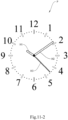
- the laser beam L of each pointer light source device 20 passes through the indication pattern of the corresponding grating 30 and is eventually projected on a projection plane P (as shown in FIG. 11-1 ) to form the corresponding laser indication.
- the grating 30A has an indication pattern 31A for the hour hand
- the grating 30B has an indication pattern 31B for the minute hand
- the grating 30C has an indication pattern 31C for the second hand, wherein all the indication patterns 31A ⁇ 31C are strip-like. More specifically, the indication pattern 31A is shorter and wider than the indication pattern 31B, and the indication pattern 31C is generally as long as but narrower than the indication pattern 31B.
- the laser beams L are projected on the projection plane P through the gratings 30A ⁇ 30C respectively to form laser indications of the hour, the minute, and the second respectively.
- the indication patterns 31A ⁇ 31C in the present invention are not limited to those described above and may be other patterns that differ from one another in length, width, or shape in order for a user to distinguish the plural laser indications projected.
- the projection plane P may be a sticker on a wall, a panel, the cover of an object, or the like in order to provide a physical clock face on which the plural laser indications can be projected.
- the physical clock face may have words, numbers, or patterns to which the laser indications can respond, thus forming a 12- or 24-hour dial.
- the projection plane P may be a virtual dial formed by projecting a light beam to a wall or curtain.
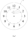
- the laser projection clock 100 further comprises a dial light source device 40 and a fixed grating 50 configured on one side of the dial light source device 40.
- the laser beam L of the dial light source device 40 is projected through the fixed grating 50 to a projection plane P on the aforesaid side of the dial light source device 40 to form clock dial pattern.
- the dial light source device 40 can be selectively turned on to project the clock dial pattern and turned off when projection of the clock dial pattern is not desired.
- the fixed grating 50 has a plurality of annularly arranged identification patterns 51.
- the identification patterns 51 comprise words, numbers, or patterns that make up pattern or format of the clock dial pattern.
- the identification patterns 51 include a plurality of circularly arranged Arabic numbers 511 that increase clockwise.
- a strip-like pattern 512 is configured on one side of each Arabic number 511, and a plurality of circular dot patterns 513 are evenly distributed between each two adjacent strip-like patterns 512.
- the strip-like patterns 512 and the circular dot patterns 513 serve as the graduation marks on a clock dial. It is worth mentioning that the identification patterns 51 are not limited to the foregoing and may include only words, numbers, or identifiable patterns that enable determination of time.
- each pointer light source device 20 comprises a laser output unit 21 and a tilt adjustment unit 22 configured on one side of the laser output unit 21.
- Each laser output unit 21 is configured for outputting a laser beam L.
- Each tilt adjustment unit 22 is configured for adjusting the output direction of the corresponding laser beam L so that at least one laser indications meet at one end, i.e., all the laser indications converge at one same point on the projection plane P.
- the pointer light sources device 20 are parallel to the axes of the gratings 30, and the output directions of the laser beams L can be changed by elements capable of light deflection (not shown).
- Each light-deflecting element may be a lens provided on one side of the corresponding grating 30 so that the corresponding laser beam L is deflected after passing through the light-deflecting element and the corresponding grating 30.
- each light-deflecting element may be one or a plurality of mirrors configured on one side of the corresponding grating 30 to change the output direction of the corresponding laser beam L.
- each of the plurality of the pointer light source devices 20 is tilted toward one side such that the projected laser indications converge at one same point on the projection plane P.
- Each tilt adjustment unit 22 comprises an X-axis fine-tuning unit 221, a Y-axis fine-tuning unit 222, and one or a plurality of elastic elements 223 configured opposite, and corresponding to an intermediate position between, the X-axis fine-tuning unit 221 and the Y-axis fine-tuning unit 222.
- Each X-axis fine-tuning unit 221 is configured on a first side of the corresponding laser output unit 21 while the corresponding Y-axis fine-tuning unit 222 is configured on a second side of the corresponding laser output unit 21, wherein the second side forms an included angle with the first side.
- Each pair of X-axis fine-tuning unit 221 and Y-axis fine-tuning unit 222 are configured for pressing the corresponding elastic elements 223 indirectly, and from different sides respectively, so as to adjust the corresponding laser output unit 21.
- the elastic elements 223 are springs or other elements capable of elastic restoration.
- each pair of X-axis fine-tuning unit 221 and Y-axis fine-tuning unit 222 in the present invention is not necessarily 90° as shown in FIG. 8 and may vary according to design or manufacture requirements; the present invention has no limitation in this regard.
- Each X-axis fine-tuning unit 221 comprises a rail 2211 with an internally threaded portion and a threaded locking unit 2212 provided on (or more specifically, threadedly coupled to) the internally threaded portion such that the threaded locking unit 2212 can be moved along the rail 2211 to one end of the rail 2211 in order to press the elastic element 223 on the opposite side of the corresponding laser output unit 21 and thereby adjust the tilt angle of the corresponding laser output unit 21 in the X-axis direction.
- Each Y-axis fine-tuning unit 222 is identical in structure to the corresponding X-axis fine-tuning unit 221 and is different from the corresponding X-axis fine-tuning unit 221 only in the direction in which it is provided.
- Each Y-axis fine-tuning unit 222 comprises a rail 2221 with an internally threaded portion and a threaded locking unit 2222 provided on (or more specifically, threadedly coupled to) the internally threaded portion such that the threaded locking unit 2222 can be moved along the rail 2221 to one end of the rail 2221 in order to press the elastic element 223 on the opposite side of the corresponding laser output unit 21 and thereby adjust the tilt angle of the corresponding laser output unit 21 in the Y-axis direction.
- the driving device 10, pointer light sources device 20, and dial light source device 40 in the present invention further have power supply wires (not shown) electrically connected to a power supply in order to be powered for operation.
- the laser projection clock of the present invention can be implemented in various ways, two of which are described below with reference to FIGS. 10 ⁇ 11-2 as two preferred embodiments. It is understood, however, that implementation of the present invention is by no means limited to the following embodiments.
Landscapes
- Physics & Mathematics (AREA)
- General Physics & Mathematics (AREA)
- Optics & Photonics (AREA)
- Semiconductor Lasers (AREA)
- Lasers (AREA)
Claims (8)
- Laserprojektionsuhr (100), umfassend:eine Antriebsvorrichtung (10), umfassend eine Vielzahl von drehenden Wellen (11) und ein Energieelement (12) zum Antreiben der Vielzahl von drehenden Wellen (11), damit diese sich mit jeweils verschiedenen Geschwindigkeiten drehen, wobei jede der drehenden Wellen (11) eine Drehachse aufweist, und die Drehachsen voneinander getrennt sind;gekennzeichnet dadurch, dasseine Vielzahl von Zeigerlichtquellenvorrichtungen (20) auf einer Seite der Antriebsvorrichtung (10) konfiguriert ist, um jeweils einen Laserstrahl (L) auszugeben, wobei die Zeigerlichtquellenvorrichtung (20) eine Laserausgabeeinheit (21) und eine Neigungseinstellungseinheit (22) umfasst, die auf einer Seite der Laserausgabeeinheit (21) konfiguriert ist, wobei eine Ausgaberichtung jedes Laserstrahls (L) einstellbar ist; undeine Vielzahl von Beugungsoptikelementen oder Hologrammen (30, 30A, 30B, 30C) auf der Vielzahl von drehenden Wellen (11) einzeln konfiguriert sind, um jeweils durch die Vielzahl von drehenden Wellen (11) gedreht zu werden, wobei jedes der Beugungsoptikelemente oder Hologramme (30, 30A, 30B, 30C) ein Indikationsmuster (31A, 31B, 31C) aufweist, und die Vielzahl von Laserstrahlen (L) auf eine entsprechende Projektionsebene (P, P1, P2, P3) projiziert werden, indem sie durch die Vielzahl von Indikationsmustern (31A, 31B, 31C) der Vielzahl von Beugungsoptikelementen oder Hologrammen (30A, 30B, 30C) hindurchgehen, um jeweils eine Vielzahl von Laserindikationen (H1, H2, H3) zu bilden.
- Laserprojektionsuhr (100) nach Anspruch 1, wobei jede der Vielzahl von Zeigerlichtquellenvorrichtungen (20) zu einer Seite hin geneigt ist, sodass die projizierten Laserindikationen in einem gleichen Punkt auf der Projektionsebene (P) konvergieren.
- Laserprojektionsuhr (100) nach Anspruch 1, wobei die Neigungseinstellungseinheit (22) Folgendes umfasst:eine X-Achse-Feinabstimmungseinheit (221);eine Y-Achse-Feinabstimmungseinheit (222); und,ein oder eine Vielzahl von elastischen Elementen (223), die gegenüberliegend konfiguriert sind und einer Zwischenposition zwischen der X-Achse-Feinabstimmungseinheit (221) und der Y-Achse-Feinabstimmungseinheit (222) entsprechen;wobei die X-Achse-Feinabstimmungseinheit (221) auf einer ersten Seite der Laserausgabeeinheit (21) konfiguriert ist, die Y-Achse-Feinabstimmungseinheit (222) auf einer zweiten Seite der Laserausgabeeinheit (21) konfiguriert ist, die einen eingeschlossenen Winkel mit der ersten Seite bildet, und die X-Achse-Feinabstimmungseinheit (221) und die Y-Achse-Feinabstimmungseinheit (222) konfiguriert sind, um das elastische Element (223) indirekt und jeweils von verschiedenen Seiten zu drücken, um die Laserausgabeeinheit (21) einzustellen.
- Laserprojektionsuhr (100) nach Anspruch 3, wobei die X-Achse-Feinabstimmungseinheit (221) eine Schiene (2211) mit einem Innengewindeabschnitt und eine Gewindeverriegelungseinheit (2212) umfasst, die gewindemäßig mit dem Innengewindeabschnitt gekoppelt ist; wobei die Gewindeverriegelungseinheit (2212) entlang der Schiene (2211) zu einem Ende der Schiene (2211) bewegt werden kann, um das elastische Element (223) auf der gegenüberliegenden Seite der Laserausgabeeinheit (21) zu drücken und dadurch den Neigungswinkel der Laserausgabeeinheit (21) in der X-Achsen-Richtung einzustellen.
- Laserprojektionsuhr (100) nach Anspruch 3, wobei die Y-Achse-Feinabstimmungseinheit (222) eine Schiene (2221) mit einem Innengewindeabschnitt und eine Gewindeverriegelungseinheit (2222) umfasst, die gewindemäßig mit dem Innengewindeabschnitt gekoppelt ist; wobei die Gewindeverriegelungseinheit (2222) entlang der Schiene (2221) zu einem Ende der Schiene (2221) bewegt werden kann, um das elastische Element/die elastischen Elemente (223) auf der gegenüberliegenden Seite der Laserausgabeeinheit (21) zu drücken und dadurch den Neigungswinkel der entsprechenden Laserausgabeeinheit (21) in der Y-Achsen-Richtung einzustellen.
- Laserprojektionsuhr (100) nach Anspruch 1 umfasst ferner eine Zifferblattlichtquellenvorrichtung (40) und ein fixiertes Gitter (50), das auf einer Seite der Zifferblattlichtquellenvorrichtung (40) konfiguriert ist; wobei der Laserstrahl (L) der Zifferblattlichtquellenvorrichtung (40) durch das fixierte Gitter (50) auf die Projektionsebene (P) auf der Zifferblattlichtquellenvorrichtung (40) projiziert wird, um ein Uhrenzifferblattmuster zu bilden.
- Laserprojektionsuhr (100) nach Anspruch 6, wobei das fixierte Gitter (50) eine Vielzahl von ringförmig angeordneten Identifikationsmustern (51) aufweist; und die ringförmig angeordneten Identifikationsmuster (51) Worte, Zahlen oder Muster umfassen.
- Laserprojektionsuhr (100) nach Anspruch 1, wobei die Antriebsvorrichtung (10) eine oder eine Vielzahl von mechanischen Uhrwerken oder Quarzuhrwerken ist.
Applications Claiming Priority (1)
| Application Number | Priority Date | Filing Date | Title |
|---|---|---|---|
| TW106138334A TWI631437B (zh) | 2017-11-06 | 2017-11-06 | 雷射投射鐘 |
Publications (3)
| Publication Number | Publication Date |
|---|---|
| EP3480666A1 EP3480666A1 (de) | 2019-05-08 |
| EP3480666C0 EP3480666C0 (de) | 2025-03-19 |
| EP3480666B1 true EP3480666B1 (de) | 2025-03-19 |
Family
ID=63959588
Family Applications (1)
| Application Number | Title | Priority Date | Filing Date |
|---|---|---|---|
| EP18191037.3A Active EP3480666B1 (de) | 2017-11-06 | 2018-08-27 | Laserprojektionsuhr |
Country Status (9)
| Country | Link |
|---|---|
| US (1) | US10838370B2 (de) |
| EP (1) | EP3480666B1 (de) |
| JP (1) | JP6463454B1 (de) |
| KR (1) | KR102185473B1 (de) |
| AU (1) | AU2018217339B2 (de) |
| ES (1) | ES3021332T3 (de) |
| PL (1) | PL3480666T3 (de) |
| RU (1) | RU2691383C1 (de) |
| TW (1) | TWI631437B (de) |
Families Citing this family (4)
| Publication number | Priority date | Publication date | Assignee | Title |
|---|---|---|---|---|
| CN110955136A (zh) * | 2019-12-16 | 2020-04-03 | 珠海莱坦科技有限公司 | 一种高度可调的激光投影钟 |
| TWI711902B (zh) * | 2020-04-30 | 2020-12-01 | 龍華科技大學 | 一種具有日晷功能的時鐘 |
| CN112904695B (zh) * | 2021-03-05 | 2022-08-09 | 正负壹先进技术(深圳)有限公司 | 一种基于中心发射的投影时钟 |
| JP7402374B1 (ja) * | 2023-02-14 | 2023-12-20 | 省吾 安部 | 時刻表示機構及び当該時刻表示機構を備えた時計 |
Citations (5)
| Publication number | Priority date | Publication date | Assignee | Title |
|---|---|---|---|---|
| US2195425A (en) * | 1938-06-23 | 1940-04-02 | Roger Henry | Projector |
| JPH06289169A (ja) * | 1993-03-30 | 1994-10-18 | Dainippon Printing Co Ltd | 時刻表示装置および時刻表示方法 |
| US6219306B1 (en) * | 1999-01-20 | 2001-04-17 | Zdzislaw Kwiatkowski | Device for projecting a dynamic spectral display |
| JP2004286706A (ja) * | 2003-03-25 | 2004-10-14 | Shinko Denshi Kk | 光時計 |
| CN202533723U (zh) * | 2012-03-29 | 2012-11-14 | 中国海洋大学 | 基于全息投影技术的激光指针钟 |
Family Cites Families (33)
| Publication number | Priority date | Publication date | Assignee | Title |
|---|---|---|---|---|
| US2009209A (en) * | 1932-03-10 | 1935-07-23 | Francis H Scantlebury | Illuminated measuring device |
| US3490226A (en) * | 1967-11-20 | 1970-01-20 | Gen Time Corp | Clock face assembly having illuminated indicating elements |
| US4461581A (en) * | 1980-05-05 | 1984-07-24 | Simon Jerome H | Light beam clock |
| US4761715A (en) * | 1987-03-25 | 1988-08-02 | Beede Electrical Instrument Co., Inc. | Laser pointer |
| US5247491A (en) * | 1991-07-29 | 1993-09-21 | Zdzislaw Kwiatkowski | Device for projecting a rainbow-like spectral display in the form of a symbol design, time indicating display and the like |
| US5247492A (en) * | 1992-10-13 | 1993-09-21 | Pan Chih H | Projection clock |
| TW245348U (de) | 1994-08-09 | 1995-04-11 | ||
| US5584569A (en) * | 1995-02-03 | 1996-12-17 | Quarton, Inc. | Semiconductor laser module |
| US20020154349A1 (en) * | 1997-02-07 | 2002-10-24 | Eads Deutschland Gmbh | Holographic display screen and method for producing the screen |
| KR20000055880A (ko) | 1999-02-10 | 2000-09-15 | 노병문 | 뽕잎과 뽕나뭇가지 혼합추출차의 제조방법 |
| US6160767A (en) * | 1999-03-12 | 2000-12-12 | Leona Lighting Design Ltd. | Clock |
| KR20010110067A (ko) * | 1999-05-31 | 2001-12-12 | 세키유지 | 기준평면 설정장치 |
| US6502757B1 (en) * | 1999-09-17 | 2003-01-07 | Dai Nippon Printing Co., Ltd. | Information recorded medium, device for reading the information, information recorded medium transfer foil, and method for producing information recorded medium |
| US6317226B1 (en) * | 1999-09-30 | 2001-11-13 | Ahead Optoelectronics, Inc. | Dot matrix hologram for hiding a moire pattern |
| US6295753B1 (en) * | 2000-02-15 | 2001-10-02 | Laser Devices, Inc. | Laser precision bore sight assembly |
| JP2001264465A (ja) * | 2000-03-14 | 2001-09-26 | Citizen Watch Co Ltd | 時 計 |
| US7252394B1 (en) * | 2003-07-03 | 2007-08-07 | Advanced Numicro Systems, Inc. | Laser projection display and illumination device with MEMS scanning mirror for indoor and outdoor applications |
| US6882597B2 (en) * | 2003-09-05 | 2005-04-19 | Dennis C. Kent | Device for displaying time in selectable display patterns |
| TWM245348U (en) * | 2003-10-20 | 2004-10-01 | Mitac Int Corp | Rotating apparatus |
| TWM275439U (en) * | 2005-05-17 | 2005-09-11 | Super Nova Optoelectronics Cor | Time display device |
| GB0618057D0 (en) * | 2006-09-14 | 2006-10-25 | Perkinelmer Ltd | Improvements in and relating to scanning confocal microscopy |
| CN102023560A (zh) * | 2009-09-22 | 2011-04-20 | 鸿富锦精密工业(深圳)有限公司 | 时间显示装置及时间显示方法 |
| US8284631B2 (en) * | 2009-12-14 | 2012-10-09 | Tirid Tech Co., Ltd. | Multimedia projection alarm clock with integrated illumination |
| CN102483937B (zh) * | 2010-01-18 | 2015-09-02 | 三菱电机株式会社 | 光学头装置以及光盘装置 |
| TWI436096B (zh) * | 2010-12-22 | 2014-05-01 | Extend Optronics Corp | 均光抗眩結構及發光裝置 |
| RU2456762C1 (ru) * | 2011-02-07 | 2012-07-20 | Алексей Владимирович Гулунов | Лазерный проектор |
| US8593912B1 (en) * | 2012-04-18 | 2013-11-26 | William Amores | Multimedia alarm clock projector |
| EP2717103B1 (de) * | 2012-10-04 | 2017-01-11 | The Swatch Group Research and Development Ltd. | Leuchtende Spiralfeder |
| US8902717B1 (en) * | 2013-06-03 | 2014-12-02 | Alex Garzon | Clockwork mechanism that enables a second hand to be positioned below the hour hand and the minute hand on a clock face |
| KR101632007B1 (ko) * | 2014-10-29 | 2016-06-21 | 엘지전자 주식회사 | 와치 타입의 제어 디바이스 |
| KR102029756B1 (ko) * | 2014-11-03 | 2019-10-08 | 삼성전자주식회사 | 웨어러블 디바이스 및 그 제어 방법 |
| CN105589607B (zh) * | 2016-02-14 | 2018-09-07 | 京东方科技集团股份有限公司 | 触控系统、触控显示系统和触控交互方法 |
| US10041763B2 (en) * | 2016-07-01 | 2018-08-07 | Bushnell Inc. | Multi-function gunsight |
-
2017
- 2017-11-06 TW TW106138334A patent/TWI631437B/zh active
- 2017-12-22 JP JP2017246009A patent/JP6463454B1/ja active Active
-
2018
- 2018-01-05 US US15/863,134 patent/US10838370B2/en active Active
- 2018-08-17 AU AU2018217339A patent/AU2018217339B2/en active Active
- 2018-08-27 EP EP18191037.3A patent/EP3480666B1/de active Active
- 2018-08-27 ES ES18191037T patent/ES3021332T3/es active Active
- 2018-08-27 PL PL18191037.3T patent/PL3480666T3/pl unknown
- 2018-09-12 KR KR1020180109043A patent/KR102185473B1/ko active Active
- 2018-09-12 RU RU2018132590A patent/RU2691383C1/ru active
Patent Citations (5)
| Publication number | Priority date | Publication date | Assignee | Title |
|---|---|---|---|---|
| US2195425A (en) * | 1938-06-23 | 1940-04-02 | Roger Henry | Projector |
| JPH06289169A (ja) * | 1993-03-30 | 1994-10-18 | Dainippon Printing Co Ltd | 時刻表示装置および時刻表示方法 |
| US6219306B1 (en) * | 1999-01-20 | 2001-04-17 | Zdzislaw Kwiatkowski | Device for projecting a dynamic spectral display |
| JP2004286706A (ja) * | 2003-03-25 | 2004-10-14 | Shinko Denshi Kk | 光時計 |
| CN202533723U (zh) * | 2012-03-29 | 2012-11-14 | 中国海洋大学 | 基于全息投影技术的激光指针钟 |
Also Published As
| Publication number | Publication date |
|---|---|
| JP6463454B1 (ja) | 2019-02-06 |
| TWI631437B (zh) | 2018-08-01 |
| EP3480666C0 (de) | 2025-03-19 |
| JP2019086501A (ja) | 2019-06-06 |
| PL3480666T3 (pl) | 2025-06-23 |
| AU2018217339B2 (en) | 2020-08-27 |
| KR102185473B1 (ko) | 2020-12-03 |
| RU2691383C1 (ru) | 2019-06-13 |
| US20190137941A1 (en) | 2019-05-09 |
| US10838370B2 (en) | 2020-11-17 |
| EP3480666A1 (de) | 2019-05-08 |
| KR20200068014A (ko) | 2020-06-15 |
| BR102018068687A2 (pt) | 2019-06-04 |
| ES3021332T3 (en) | 2025-05-26 |
| AU2018217339A1 (en) | 2019-05-23 |
| TW201918804A (zh) | 2019-05-16 |
Similar Documents
| Publication | Publication Date | Title |
|---|---|---|
| EP3480666B1 (de) | Laserprojektionsuhr | |
| US6894951B1 (en) | Watch movement with hand display | |
| CN100449424C (zh) | 具有以十进制系统为基础的时间信息的模拟显示时计 | |
| CN102939569B (zh) | 用于表的表盘模块和设置有表盘模块的表 | |
| US7492669B2 (en) | Timepiece attached with calendar mechanism having first date indicator and second date indicator | |
| US20120075960A1 (en) | Time Display Device and Method of Displaying Time | |
| JP2019052881A (ja) | 電子時計 | |
| CN107179672A (zh) | 储能机构、机芯以及钟表 | |
| US2886942A (en) | Time indicating device for watches, clocks and the like | |
| US11249442B2 (en) | Display system for a timepiece | |
| US3708971A (en) | Tide indicating timepiece | |
| JP2006275525A (ja) | 回転表示機能付時計 | |
| CN100594451C (zh) | 包括多个类型的指针操作轮系的多功能时计 | |
| CN111788528B (zh) | 包括在机芯的两侧上同时可见的显示构件的钟表机芯 | |
| CN109782564B (zh) | 雷射投射钟 | |
| JP2612234B2 (ja) | 回転式表示手段を有する時計 | |
| US20070097794A1 (en) | Timepiece with a fan-shaped hand motion display mechanism | |
| US5114345A (en) | Process and apparatus for representing tidal movement | |
| CN109557797A (zh) | 轮系装置及钟表 | |
| BR102018068687B1 (pt) | Relógio de projeção a laser | |
| CN201594178U (zh) | 时钟 | |
| US1389666A (en) | Clock, watch, and the like timekeeping instrument | |
| JP3177523U (ja) | 時計用文字盤および時計 | |
| HK40039269A (en) | Timepiece movement comprising a display member simultaneously visible on both sides of the movement | |
| HK40039269B (en) | Timepiece movement comprising a display member simultaneously visible on both sides of the movement |
Legal Events
| Date | Code | Title | Description |
|---|---|---|---|
| PUAI | Public reference made under article 153(3) epc to a published international application that has entered the european phase |
Free format text: ORIGINAL CODE: 0009012 |
|
| STAA | Information on the status of an ep patent application or granted ep patent |
Free format text: STATUS: THE APPLICATION HAS BEEN PUBLISHED |
|
| AK | Designated contracting states |
Kind code of ref document: A1 Designated state(s): AL AT BE BG CH CY CZ DE DK EE ES FI FR GB GR HR HU IE IS IT LI LT LU LV MC MK MT NL NO PL PT RO RS SE SI SK SM TR |
|
| AX | Request for extension of the european patent |
Extension state: BA ME |
|
| STAA | Information on the status of an ep patent application or granted ep patent |
Free format text: STATUS: REQUEST FOR EXAMINATION WAS MADE |
|
| 17P | Request for examination filed |
Effective date: 20191105 |
|
| RBV | Designated contracting states (corrected) |
Designated state(s): AL AT BE BG CH CY CZ DE DK EE ES FI FR GB GR HR HU IE IS IT LI LT LU LV MC MK MT NL NO PL PT RO RS SE SI SK SM TR |
|
| STAA | Information on the status of an ep patent application or granted ep patent |
Free format text: STATUS: EXAMINATION IS IN PROGRESS |
|
| 17Q | First examination report despatched |
Effective date: 20210219 |
|
| APBK | Appeal reference recorded |
Free format text: ORIGINAL CODE: EPIDOSNREFNE |
|
| APBN | Date of receipt of notice of appeal recorded |
Free format text: ORIGINAL CODE: EPIDOSNNOA2E |
|
| APBR | Date of receipt of statement of grounds of appeal recorded |
Free format text: ORIGINAL CODE: EPIDOSNNOA3E |
|
| APAF | Appeal reference modified |
Free format text: ORIGINAL CODE: EPIDOSCREFNE |
|
| APAF | Appeal reference modified |
Free format text: ORIGINAL CODE: EPIDOSCREFNE |
|
| APBX | Invitation to file observations in appeal sent |
Free format text: ORIGINAL CODE: EPIDOSNOBA2E |
|
| APBT | Appeal procedure closed |
Free format text: ORIGINAL CODE: EPIDOSNNOA9E |
|
| GRAP | Despatch of communication of intention to grant a patent |
Free format text: ORIGINAL CODE: EPIDOSNIGR1 |
|
| STAA | Information on the status of an ep patent application or granted ep patent |
Free format text: STATUS: GRANT OF PATENT IS INTENDED |
|
| INTG | Intention to grant announced |
Effective date: 20241017 |
|
| GRAS | Grant fee paid |
Free format text: ORIGINAL CODE: EPIDOSNIGR3 |
|
| GRAA | (expected) grant |
Free format text: ORIGINAL CODE: 0009210 |
|
| STAA | Information on the status of an ep patent application or granted ep patent |
Free format text: STATUS: THE PATENT HAS BEEN GRANTED |
|
| RAP1 | Party data changed (applicant data changed or rights of an application transferred) |
Owner name: ZHANGZHOU QIXIANG INTELLIGENT TECHNOLOGY CO., LTD |
|
| RIN1 | Information on inventor provided before grant (corrected) |
Inventor name: HSU, CHIA CHI Inventor name: HSU, CHIA-WEI |
|
| AK | Designated contracting states |
Kind code of ref document: B1 Designated state(s): AL AT BE BG CH CY CZ DE DK EE ES FI FR GB GR HR HU IE IS IT LI LT LU LV MC MK MT NL NO PL PT RO RS SE SI SK SM TR |
|
| REG | Reference to a national code |
Ref country code: GB Ref legal event code: FG4D |
|
| REG | Reference to a national code |
Ref country code: CH Ref legal event code: EP |
|
| REG | Reference to a national code |
Ref country code: DE Ref legal event code: R096 Ref document number: 602018080214 Country of ref document: DE |
|
| REG | Reference to a national code |
Ref country code: IE Ref legal event code: FG4D |
|
| U01 | Request for unitary effect filed |
Effective date: 20250409 |
|
| U07 | Unitary effect registered |
Designated state(s): AT BE BG DE DK EE FI FR IT LT LU LV MT NL PT RO SE SI Effective date: 20250415 |
|
| REG | Reference to a national code |
Ref country code: ES Ref legal event code: FG2A Ref document number: 3021332 Country of ref document: ES Kind code of ref document: T3 Effective date: 20250526 |
|
| PG25 | Lapsed in a contracting state [announced via postgrant information from national office to epo] |
Ref country code: RS Free format text: LAPSE BECAUSE OF FAILURE TO SUBMIT A TRANSLATION OF THE DESCRIPTION OR TO PAY THE FEE WITHIN THE PRESCRIBED TIME-LIMIT Effective date: 20250619 |
|
| PG25 | Lapsed in a contracting state [announced via postgrant information from national office to epo] |
Ref country code: NO Free format text: LAPSE BECAUSE OF FAILURE TO SUBMIT A TRANSLATION OF THE DESCRIPTION OR TO PAY THE FEE WITHIN THE PRESCRIBED TIME-LIMIT Effective date: 20250619 |
|
| PG25 | Lapsed in a contracting state [announced via postgrant information from national office to epo] |
Ref country code: HR Free format text: LAPSE BECAUSE OF FAILURE TO SUBMIT A TRANSLATION OF THE DESCRIPTION OR TO PAY THE FEE WITHIN THE PRESCRIBED TIME-LIMIT Effective date: 20250319 |
|
| PG25 | Lapsed in a contracting state [announced via postgrant information from national office to epo] |
Ref country code: GR Free format text: LAPSE BECAUSE OF FAILURE TO SUBMIT A TRANSLATION OF THE DESCRIPTION OR TO PAY THE FEE WITHIN THE PRESCRIBED TIME-LIMIT Effective date: 20250620 |
|
| U20 | Renewal fee for the european patent with unitary effect paid |
Year of fee payment: 8 Effective date: 20250828 |
|
| PG25 | Lapsed in a contracting state [announced via postgrant information from national office to epo] |
Ref country code: SM Free format text: LAPSE BECAUSE OF FAILURE TO SUBMIT A TRANSLATION OF THE DESCRIPTION OR TO PAY THE FEE WITHIN THE PRESCRIBED TIME-LIMIT Effective date: 20250319 |
|
| PGFP | Annual fee paid to national office [announced via postgrant information from national office to epo] |
Ref country code: ES Payment date: 20250903 Year of fee payment: 8 |
|
| PGFP | Annual fee paid to national office [announced via postgrant information from national office to epo] |
Ref country code: PL Payment date: 20250821 Year of fee payment: 8 Ref country code: TR Payment date: 20250825 Year of fee payment: 8 |
|
| PGFP | Annual fee paid to national office [announced via postgrant information from national office to epo] |
Ref country code: CH Payment date: 20250919 Year of fee payment: 8 |
|
| PG25 | Lapsed in a contracting state [announced via postgrant information from national office to epo] |
Ref country code: CZ Free format text: LAPSE BECAUSE OF FAILURE TO SUBMIT A TRANSLATION OF THE DESCRIPTION OR TO PAY THE FEE WITHIN THE PRESCRIBED TIME-LIMIT Effective date: 20250319 |
|
| PG25 | Lapsed in a contracting state [announced via postgrant information from national office to epo] |
Ref country code: SK Free format text: LAPSE BECAUSE OF FAILURE TO SUBMIT A TRANSLATION OF THE DESCRIPTION OR TO PAY THE FEE WITHIN THE PRESCRIBED TIME-LIMIT Effective date: 20250319 |
|
| PG25 | Lapsed in a contracting state [announced via postgrant information from national office to epo] |
Ref country code: IS Free format text: LAPSE BECAUSE OF FAILURE TO SUBMIT A TRANSLATION OF THE DESCRIPTION OR TO PAY THE FEE WITHIN THE PRESCRIBED TIME-LIMIT Effective date: 20250719 |
|
| U1N | Appointed representative for the unitary patent procedure changed after the registration of the unitary effect |
Representative=s name: SANTARELLI; FR |
|
| PGFP | Annual fee paid to national office [announced via postgrant information from national office to epo] |
Ref country code: GB Payment date: 20251127 Year of fee payment: 8 |
|
| PLBE | No opposition filed within time limit |
Free format text: ORIGINAL CODE: 0009261 |
|
| STAA | Information on the status of an ep patent application or granted ep patent |
Free format text: STATUS: NO OPPOSITION FILED WITHIN TIME LIMIT |
|
| REG | Reference to a national code |
Ref country code: CH Ref legal event code: L10 Free format text: ST27 STATUS EVENT CODE: U-0-0-L10-L00 (AS PROVIDED BY THE NATIONAL OFFICE) Effective date: 20260128 |
|
| 26N | No opposition filed |
Effective date: 20251222 |
|
| PG25 | Lapsed in a contracting state [announced via postgrant information from national office to epo] |
Ref country code: MC Free format text: LAPSE BECAUSE OF FAILURE TO SUBMIT A TRANSLATION OF THE DESCRIPTION OR TO PAY THE FEE WITHIN THE PRESCRIBED TIME-LIMIT Effective date: 20250319 |