EP3480592A2 - System for non-destructively inspecting and determining sealing of aluminum pouch by using ultrasonic waves - Google Patents
System for non-destructively inspecting and determining sealing of aluminum pouch by using ultrasonic waves Download PDFInfo
- Publication number
- EP3480592A2 EP3480592A2 EP18751271.0A EP18751271A EP3480592A2 EP 3480592 A2 EP3480592 A2 EP 3480592A2 EP 18751271 A EP18751271 A EP 18751271A EP 3480592 A2 EP3480592 A2 EP 3480592A2
- Authority
- EP
- European Patent Office
- Prior art keywords
- destructive inspection
- ultrasonic
- sealing
- inspection
- judgment system
- Prior art date
- Legal status (The legal status is an assumption and is not a legal conclusion. Google has not performed a legal analysis and makes no representation as to the accuracy of the status listed.)
- Granted
Links
Images



Classifications
-
- G—PHYSICS
- G01—MEASURING; TESTING
- G01N—INVESTIGATING OR ANALYSING MATERIALS BY DETERMINING THEIR CHEMICAL OR PHYSICAL PROPERTIES
- G01N29/00—Investigating or analysing materials by the use of ultrasonic, sonic or infrasonic waves; Visualisation of the interior of objects by transmitting ultrasonic or sonic waves through the object
- G01N29/44—Processing the detected response signal, e.g. electronic circuits specially adapted therefor
- G01N29/4445—Classification of defects
-
- G—PHYSICS
- G01—MEASURING; TESTING
- G01N—INVESTIGATING OR ANALYSING MATERIALS BY DETERMINING THEIR CHEMICAL OR PHYSICAL PROPERTIES
- G01N29/00—Investigating or analysing materials by the use of ultrasonic, sonic or infrasonic waves; Visualisation of the interior of objects by transmitting ultrasonic or sonic waves through the object
- G01N29/22—Details, e.g. general constructional or apparatus details
- G01N29/24—Probes
- G01N29/2418—Probes using optoacoustic interaction with the material, e.g. laser radiation, photoacoustics
-
- B—PERFORMING OPERATIONS; TRANSPORTING
- B29—WORKING OF PLASTICS; WORKING OF SUBSTANCES IN A PLASTIC STATE IN GENERAL
- B29C—SHAPING OR JOINING OF PLASTICS; SHAPING OF MATERIAL IN A PLASTIC STATE, NOT OTHERWISE PROVIDED FOR; AFTER-TREATMENT OF THE SHAPED PRODUCTS, e.g. REPAIRING
- B29C65/00—Joining or sealing of preformed parts, e.g. welding of plastics materials; Apparatus therefor
- B29C65/02—Joining or sealing of preformed parts, e.g. welding of plastics materials; Apparatus therefor by heating, with or without pressure
-
- B—PERFORMING OPERATIONS; TRANSPORTING
- B29—WORKING OF PLASTICS; WORKING OF SUBSTANCES IN A PLASTIC STATE IN GENERAL
- B29C—SHAPING OR JOINING OF PLASTICS; SHAPING OF MATERIAL IN A PLASTIC STATE, NOT OTHERWISE PROVIDED FOR; AFTER-TREATMENT OF THE SHAPED PRODUCTS, e.g. REPAIRING
- B29C65/00—Joining or sealing of preformed parts, e.g. welding of plastics materials; Apparatus therefor
- B29C65/76—Making non-permanent or releasable joints
-
- B—PERFORMING OPERATIONS; TRANSPORTING
- B29—WORKING OF PLASTICS; WORKING OF SUBSTANCES IN A PLASTIC STATE IN GENERAL
- B29C—SHAPING OR JOINING OF PLASTICS; SHAPING OF MATERIAL IN A PLASTIC STATE, NOT OTHERWISE PROVIDED FOR; AFTER-TREATMENT OF THE SHAPED PRODUCTS, e.g. REPAIRING
- B29C65/00—Joining or sealing of preformed parts, e.g. welding of plastics materials; Apparatus therefor
- B29C65/82—Testing the joint
- B29C65/8253—Testing the joint by the use of waves or particle radiation, e.g. visual examination, scanning electron microscopy, or X-rays
-
- B—PERFORMING OPERATIONS; TRANSPORTING
- B29—WORKING OF PLASTICS; WORKING OF SUBSTANCES IN A PLASTIC STATE IN GENERAL
- B29C—SHAPING OR JOINING OF PLASTICS; SHAPING OF MATERIAL IN A PLASTIC STATE, NOT OTHERWISE PROVIDED FOR; AFTER-TREATMENT OF THE SHAPED PRODUCTS, e.g. REPAIRING
- B29C65/00—Joining or sealing of preformed parts, e.g. welding of plastics materials; Apparatus therefor
- B29C65/82—Testing the joint
- B29C65/8292—Testing the joint by the use of ultrasonic, sonic or infrasonic waves
-
- B—PERFORMING OPERATIONS; TRANSPORTING
- B29—WORKING OF PLASTICS; WORKING OF SUBSTANCES IN A PLASTIC STATE IN GENERAL
- B29C—SHAPING OR JOINING OF PLASTICS; SHAPING OF MATERIAL IN A PLASTIC STATE, NOT OTHERWISE PROVIDED FOR; AFTER-TREATMENT OF THE SHAPED PRODUCTS, e.g. REPAIRING
- B29C66/00—General aspects of processes or apparatus for joining preformed parts
- B29C66/01—General aspects dealing with the joint area or with the area to be joined
- B29C66/05—Particular design of joint configurations
- B29C66/10—Particular design of joint configurations particular design of the joint cross-sections
- B29C66/11—Joint cross-sections comprising a single joint-segment, i.e. one of the parts to be joined comprising a single joint-segment in the joint cross-section
- B29C66/112—Single lapped joints
- B29C66/1122—Single lap to lap joints, i.e. overlap joints
-
- B—PERFORMING OPERATIONS; TRANSPORTING
- B29—WORKING OF PLASTICS; WORKING OF SUBSTANCES IN A PLASTIC STATE IN GENERAL
- B29C—SHAPING OR JOINING OF PLASTICS; SHAPING OF MATERIAL IN A PLASTIC STATE, NOT OTHERWISE PROVIDED FOR; AFTER-TREATMENT OF THE SHAPED PRODUCTS, e.g. REPAIRING
- B29C66/00—General aspects of processes or apparatus for joining preformed parts
- B29C66/40—General aspects of joining substantially flat articles, e.g. plates, sheets or web-like materials; Making flat seams in tubular or hollow articles; Joining single elements to substantially flat surfaces
- B29C66/41—Joining substantially flat articles ; Making flat seams in tubular or hollow articles
- B29C66/43—Joining a relatively small portion of the surface of said articles
-
- B—PERFORMING OPERATIONS; TRANSPORTING
- B29—WORKING OF PLASTICS; WORKING OF SUBSTANCES IN A PLASTIC STATE IN GENERAL
- B29C—SHAPING OR JOINING OF PLASTICS; SHAPING OF MATERIAL IN A PLASTIC STATE, NOT OTHERWISE PROVIDED FOR; AFTER-TREATMENT OF THE SHAPED PRODUCTS, e.g. REPAIRING
- B29C66/00—General aspects of processes or apparatus for joining preformed parts
- B29C66/40—General aspects of joining substantially flat articles, e.g. plates, sheets or web-like materials; Making flat seams in tubular or hollow articles; Joining single elements to substantially flat surfaces
- B29C66/41—Joining substantially flat articles ; Making flat seams in tubular or hollow articles
- B29C66/43—Joining a relatively small portion of the surface of said articles
- B29C66/431—Joining the articles to themselves
- B29C66/4312—Joining the articles to themselves for making flat seams in tubular or hollow articles, e.g. transversal seams
- B29C66/43121—Closing the ends of tubular or hollow single articles, e.g. closing the ends of bags
-
- B—PERFORMING OPERATIONS; TRANSPORTING
- B29—WORKING OF PLASTICS; WORKING OF SUBSTANCES IN A PLASTIC STATE IN GENERAL
- B29C—SHAPING OR JOINING OF PLASTICS; SHAPING OF MATERIAL IN A PLASTIC STATE, NOT OTHERWISE PROVIDED FOR; AFTER-TREATMENT OF THE SHAPED PRODUCTS, e.g. REPAIRING
- B29C66/00—General aspects of processes or apparatus for joining preformed parts
- B29C66/40—General aspects of joining substantially flat articles, e.g. plates, sheets or web-like materials; Making flat seams in tubular or hollow articles; Joining single elements to substantially flat surfaces
- B29C66/41—Joining substantially flat articles ; Making flat seams in tubular or hollow articles
- B29C66/43—Joining a relatively small portion of the surface of said articles
- B29C66/433—Casing-in, i.e. enclosing an element between two sheets by an outlined seam
-
- B—PERFORMING OPERATIONS; TRANSPORTING
- B29—WORKING OF PLASTICS; WORKING OF SUBSTANCES IN A PLASTIC STATE IN GENERAL
- B29C—SHAPING OR JOINING OF PLASTICS; SHAPING OF MATERIAL IN A PLASTIC STATE, NOT OTHERWISE PROVIDED FOR; AFTER-TREATMENT OF THE SHAPED PRODUCTS, e.g. REPAIRING
- B29C66/00—General aspects of processes or apparatus for joining preformed parts
- B29C66/70—General aspects of processes or apparatus for joining preformed parts characterised by the composition, physical properties or the structure of the material of the parts to be joined; Joining with non-plastics material
- B29C66/71—General aspects of processes or apparatus for joining preformed parts characterised by the composition, physical properties or the structure of the material of the parts to be joined; Joining with non-plastics material characterised by the composition of the plastics material of the parts to be joined
-
- B—PERFORMING OPERATIONS; TRANSPORTING
- B29—WORKING OF PLASTICS; WORKING OF SUBSTANCES IN A PLASTIC STATE IN GENERAL
- B29C—SHAPING OR JOINING OF PLASTICS; SHAPING OF MATERIAL IN A PLASTIC STATE, NOT OTHERWISE PROVIDED FOR; AFTER-TREATMENT OF THE SHAPED PRODUCTS, e.g. REPAIRING
- B29C66/00—General aspects of processes or apparatus for joining preformed parts
- B29C66/70—General aspects of processes or apparatus for joining preformed parts characterised by the composition, physical properties or the structure of the material of the parts to be joined; Joining with non-plastics material
- B29C66/72—General aspects of processes or apparatus for joining preformed parts characterised by the composition, physical properties or the structure of the material of the parts to be joined; Joining with non-plastics material characterised by the structure of the material of the parts to be joined
- B29C66/723—General aspects of processes or apparatus for joining preformed parts characterised by the composition, physical properties or the structure of the material of the parts to be joined; Joining with non-plastics material characterised by the structure of the material of the parts to be joined being multi-layered
- B29C66/7232—General aspects of processes or apparatus for joining preformed parts characterised by the composition, physical properties or the structure of the material of the parts to be joined; Joining with non-plastics material characterised by the structure of the material of the parts to be joined being multi-layered comprising a non-plastics layer
- B29C66/72321—General aspects of processes or apparatus for joining preformed parts characterised by the composition, physical properties or the structure of the material of the parts to be joined; Joining with non-plastics material characterised by the structure of the material of the parts to be joined being multi-layered comprising a non-plastics layer consisting of metals or their alloys
-
- G—PHYSICS
- G01—MEASURING; TESTING
- G01M—TESTING STATIC OR DYNAMIC BALANCE OF MACHINES OR STRUCTURES; TESTING OF STRUCTURES OR APPARATUS, NOT OTHERWISE PROVIDED FOR
- G01M3/00—Investigating fluid-tightness of structures
- G01M3/02—Investigating fluid-tightness of structures by using fluid or vacuum
- G01M3/04—Investigating fluid-tightness of structures by using fluid or vacuum by detecting the presence of fluid at the leakage point
- G01M3/24—Investigating fluid-tightness of structures by using fluid or vacuum by detecting the presence of fluid at the leakage point using infrasonic, sonic or ultrasonic vibrations
-
- G—PHYSICS
- G01—MEASURING; TESTING
- G01N—INVESTIGATING OR ANALYSING MATERIALS BY DETERMINING THEIR CHEMICAL OR PHYSICAL PROPERTIES
- G01N29/00—Investigating or analysing materials by the use of ultrasonic, sonic or infrasonic waves; Visualisation of the interior of objects by transmitting ultrasonic or sonic waves through the object
- G01N29/04—Analysing solids
- G01N29/041—Analysing solids on the surface of the material, e.g. using Lamb, Rayleigh or shear waves
-
- G—PHYSICS
- G01—MEASURING; TESTING
- G01N—INVESTIGATING OR ANALYSING MATERIALS BY DETERMINING THEIR CHEMICAL OR PHYSICAL PROPERTIES
- G01N29/00—Investigating or analysing materials by the use of ultrasonic, sonic or infrasonic waves; Visualisation of the interior of objects by transmitting ultrasonic or sonic waves through the object
- G01N29/04—Analysing solids
- G01N29/043—Analysing solids in the interior, e.g. by shear waves
-
- G—PHYSICS
- G01—MEASURING; TESTING
- G01N—INVESTIGATING OR ANALYSING MATERIALS BY DETERMINING THEIR CHEMICAL OR PHYSICAL PROPERTIES
- G01N29/00—Investigating or analysing materials by the use of ultrasonic, sonic or infrasonic waves; Visualisation of the interior of objects by transmitting ultrasonic or sonic waves through the object
- G01N29/04—Analysing solids
- G01N29/06—Visualisation of the interior, e.g. acoustic microscopy
- G01N29/0609—Display arrangements, e.g. colour displays
-
- G—PHYSICS
- G01—MEASURING; TESTING
- G01N—INVESTIGATING OR ANALYSING MATERIALS BY DETERMINING THEIR CHEMICAL OR PHYSICAL PROPERTIES
- G01N29/00—Investigating or analysing materials by the use of ultrasonic, sonic or infrasonic waves; Visualisation of the interior of objects by transmitting ultrasonic or sonic waves through the object
- G01N29/04—Analysing solids
- G01N29/06—Visualisation of the interior, e.g. acoustic microscopy
- G01N29/0654—Imaging
- G01N29/069—Defect imaging, localisation and sizing using, e.g. time of flight diffraction [TOFD], synthetic aperture focusing technique [SAFT], Amplituden-Laufzeit-Ortskurven [ALOK] technique
-
- G—PHYSICS
- G01—MEASURING; TESTING
- G01N—INVESTIGATING OR ANALYSING MATERIALS BY DETERMINING THEIR CHEMICAL OR PHYSICAL PROPERTIES
- G01N29/00—Investigating or analysing materials by the use of ultrasonic, sonic or infrasonic waves; Visualisation of the interior of objects by transmitting ultrasonic or sonic waves through the object
- G01N29/04—Analysing solids
- G01N29/11—Analysing solids by measuring attenuation of acoustic waves
-
- G—PHYSICS
- G01—MEASURING; TESTING
- G01N—INVESTIGATING OR ANALYSING MATERIALS BY DETERMINING THEIR CHEMICAL OR PHYSICAL PROPERTIES
- G01N29/00—Investigating or analysing materials by the use of ultrasonic, sonic or infrasonic waves; Visualisation of the interior of objects by transmitting ultrasonic or sonic waves through the object
- G01N29/36—Detecting the response signal, e.g. electronic circuits specially adapted therefor
-
- B—PERFORMING OPERATIONS; TRANSPORTING
- B29—WORKING OF PLASTICS; WORKING OF SUBSTANCES IN A PLASTIC STATE IN GENERAL
- B29C—SHAPING OR JOINING OF PLASTICS; SHAPING OF MATERIAL IN A PLASTIC STATE, NOT OTHERWISE PROVIDED FOR; AFTER-TREATMENT OF THE SHAPED PRODUCTS, e.g. REPAIRING
- B29C65/00—Joining or sealing of preformed parts, e.g. welding of plastics materials; Apparatus therefor
- B29C65/02—Joining or sealing of preformed parts, e.g. welding of plastics materials; Apparatus therefor by heating, with or without pressure
- B29C65/08—Joining or sealing of preformed parts, e.g. welding of plastics materials; Apparatus therefor by heating, with or without pressure using ultrasonic vibrations
-
- B—PERFORMING OPERATIONS; TRANSPORTING
- B29—WORKING OF PLASTICS; WORKING OF SUBSTANCES IN A PLASTIC STATE IN GENERAL
- B29C—SHAPING OR JOINING OF PLASTICS; SHAPING OF MATERIAL IN A PLASTIC STATE, NOT OTHERWISE PROVIDED FOR; AFTER-TREATMENT OF THE SHAPED PRODUCTS, e.g. REPAIRING
- B29C65/00—Joining or sealing of preformed parts, e.g. welding of plastics materials; Apparatus therefor
- B29C65/02—Joining or sealing of preformed parts, e.g. welding of plastics materials; Apparatus therefor by heating, with or without pressure
- B29C65/14—Joining or sealing of preformed parts, e.g. welding of plastics materials; Apparatus therefor by heating, with or without pressure using wave energy, i.e. electromagnetic radiation, or particle radiation
- B29C65/16—Laser beams
-
- B—PERFORMING OPERATIONS; TRANSPORTING
- B29—WORKING OF PLASTICS; WORKING OF SUBSTANCES IN A PLASTIC STATE IN GENERAL
- B29C—SHAPING OR JOINING OF PLASTICS; SHAPING OF MATERIAL IN A PLASTIC STATE, NOT OTHERWISE PROVIDED FOR; AFTER-TREATMENT OF THE SHAPED PRODUCTS, e.g. REPAIRING
- B29C65/00—Joining or sealing of preformed parts, e.g. welding of plastics materials; Apparatus therefor
- B29C65/82—Testing the joint
- B29C65/8261—Testing the joint by the use of thermal means
-
- B—PERFORMING OPERATIONS; TRANSPORTING
- B29—WORKING OF PLASTICS; WORKING OF SUBSTANCES IN A PLASTIC STATE IN GENERAL
- B29K—INDEXING SCHEME ASSOCIATED WITH SUBCLASSES B29B, B29C OR B29D, RELATING TO MOULDING MATERIALS OR TO MATERIALS FOR MOULDS, REINFORCEMENTS, FILLERS OR PREFORMED PARTS, e.g. INSERTS
- B29K2705/00—Use of metals, their alloys or their compounds, for preformed parts, e.g. for inserts
- B29K2705/02—Aluminium
-
- B—PERFORMING OPERATIONS; TRANSPORTING
- B29—WORKING OF PLASTICS; WORKING OF SUBSTANCES IN A PLASTIC STATE IN GENERAL
- B29L—INDEXING SCHEME ASSOCIATED WITH SUBCLASS B29C, RELATING TO PARTICULAR ARTICLES
- B29L2031/00—Other particular articles
- B29L2031/34—Electrical apparatus, e.g. sparking plugs or parts thereof
- B29L2031/3468—Batteries, accumulators or fuel cells
-
- B—PERFORMING OPERATIONS; TRANSPORTING
- B29—WORKING OF PLASTICS; WORKING OF SUBSTANCES IN A PLASTIC STATE IN GENERAL
- B29L—INDEXING SCHEME ASSOCIATED WITH SUBCLASS B29C, RELATING TO PARTICULAR ARTICLES
- B29L2031/00—Other particular articles
- B29L2031/712—Containers; Packaging elements or accessories, Packages
- B29L2031/7128—Bags, sacks, sachets
-
- G—PHYSICS
- G01—MEASURING; TESTING
- G01N—INVESTIGATING OR ANALYSING MATERIALS BY DETERMINING THEIR CHEMICAL OR PHYSICAL PROPERTIES
- G01N2291/00—Indexing codes associated with group G01N29/00
- G01N2291/01—Indexing codes associated with the measuring variable
- G01N2291/015—Attenuation, scattering
-
- G—PHYSICS
- G01—MEASURING; TESTING
- G01N—INVESTIGATING OR ANALYSING MATERIALS BY DETERMINING THEIR CHEMICAL OR PHYSICAL PROPERTIES
- G01N2291/00—Indexing codes associated with group G01N29/00
- G01N2291/02—Indexing codes associated with the analysed material
- G01N2291/023—Solids
- G01N2291/0235—Plastics; polymers; soft materials, e.g. rubber
-
- G—PHYSICS
- G01—MEASURING; TESTING
- G01N—INVESTIGATING OR ANALYSING MATERIALS BY DETERMINING THEIR CHEMICAL OR PHYSICAL PROPERTIES
- G01N2291/00—Indexing codes associated with group G01N29/00
- G01N2291/02—Indexing codes associated with the analysed material
- G01N2291/028—Material parameters
- G01N2291/0289—Internal structure, e.g. defects, grain size, texture
-
- G—PHYSICS
- G01—MEASURING; TESTING
- G01N—INVESTIGATING OR ANALYSING MATERIALS BY DETERMINING THEIR CHEMICAL OR PHYSICAL PROPERTIES
- G01N2291/00—Indexing codes associated with group G01N29/00
- G01N2291/04—Wave modes and trajectories
- G01N2291/048—Transmission, i.e. analysed material between transmitter and receiver
-
- G—PHYSICS
- G01—MEASURING; TESTING
- G01N—INVESTIGATING OR ANALYSING MATERIALS BY DETERMINING THEIR CHEMICAL OR PHYSICAL PROPERTIES
- G01N2291/00—Indexing codes associated with group G01N29/00
- G01N2291/10—Number of transducers
- G01N2291/102—Number of transducers one emitter, one receiver
-
- G—PHYSICS
- G01—MEASURING; TESTING
- G01N—INVESTIGATING OR ANALYSING MATERIALS BY DETERMINING THEIR CHEMICAL OR PHYSICAL PROPERTIES
- G01N2291/00—Indexing codes associated with group G01N29/00
- G01N2291/26—Scanned objects
- G01N2291/263—Surfaces
- G01N2291/2632—Surfaces flat
-
- G—PHYSICS
- G01—MEASURING; TESTING
- G01N—INVESTIGATING OR ANALYSING MATERIALS BY DETERMINING THEIR CHEMICAL OR PHYSICAL PROPERTIES
- G01N2291/00—Indexing codes associated with group G01N29/00
- G01N2291/26—Scanned objects
- G01N2291/267—Welds
-
- G—PHYSICS
- G01—MEASURING; TESTING
- G01N—INVESTIGATING OR ANALYSING MATERIALS BY DETERMINING THEIR CHEMICAL OR PHYSICAL PROPERTIES
- G01N2291/00—Indexing codes associated with group G01N29/00
- G01N2291/26—Scanned objects
- G01N2291/267—Welds
- G01N2291/2677—Lapp welding
-
- G—PHYSICS
- G01—MEASURING; TESTING
- G01N—INVESTIGATING OR ANALYSING MATERIALS BY DETERMINING THEIR CHEMICAL OR PHYSICAL PROPERTIES
- G01N2291/00—Indexing codes associated with group G01N29/00
- G01N2291/26—Scanned objects
- G01N2291/269—Various geometry objects
- G01N2291/2695—Bottles, containers
Definitions
- the present invention relates to a non-destructive inspection judgment system for aluminum pouch sealing using ultrasonic waves in which, using transmittance of ultrasonic waves, a region with a high density (sealed part) at a transmitting portion with a high transmittance is displayed in red, and a region with a low density (air part) at a transmitting portion with a low transmittance is displayed in blue so that an unsealed portion of an aluminum pouch is detected and checked through a non-destructive inspection
- the non-destructive inspection judgment system includes an ultrasonic wave generation data controller including processing software that detects an unsealed portion in a portion of an aluminum pouch that has been sealed through a non-destructive inspection using ultrasonic waves, sets a judgment reference value since a length of a sealing width is measurable, processes measurement data, and performs automatic judgment, a sealing defect presence judger, and a display so that judgment upon a non-destructive and non-contact inspection is automated, and a gas leakage that occurs due
- lithium secondary batteries which exhibit high energy density and operating potential, long cycle life, and low self-discharge rate, have been commercialized and widely used.
- Ni-MH secondary batteries are mainly used as power sources for electric vehicles (EV), hybrid electric vehicles (HEV), and the like
- lithium secondary batteries having high energy density, high discharge voltage and high output stability as power sources for electric vehicles (EV), hybrid electric vehicles (HEV), and the like have been vigorously carried out, and some of the lithium secondary batteries have been commercialized.
- the lithium secondary battery has a structure in which a non-aqueous electrolyte containing a lithium salt is impregnated in an electrode assembly having a porous separator interposed between a positive electrode and a negative electrode, each of which is coated with an active material on a current collector.
- the electrode assembly that has a structure consisting of a positive electrode, a separator, and a negative electrode to form a secondary battery is mainly classified into types such as a jelly-roll type (winding type), a stack type (stacked type) and a stack/folding type, which is a type in which the jelly-roll type and the stack type are combined, in accordance with a structure thereof.
- types such as a jelly-roll type (winding type), a stack type (stacked type) and a stack/folding type, which is a type in which the jelly-roll type and the stack type are combined, in accordance with a structure thereof.
- Such an electrode assembly includes an electrode tab for connection with an external terminal at each electrode.
- such an electrode tab is coupled to an electrode lead for connection with an external terminal by welding.
- ultrasonic welding is mainly used for the welding. This is because, when resistance welding, laser welding, or the like is used, the performance of the battery may be degraded due to application of excessive energy to the electrode assembly.
- the welded portion may be separated in the process of combining a battery module or a battery pack using a battery cell.
- a welding portion between a tab and a lead is separated in a battery module or a battery pack manufactured by connecting a plurality of battery cells in series or in parallel, since the entire battery pack may fail to exhibit its function, this is considered to be a serious defect.
- ultrasonic waves in the range of 20 to 40 kHz are incident on a test body having a failure, and some of the elastic energy of the incident ultrasonic waves is converted into thermal energy due to the thermoelastic effect at a coupling part.
- an infrared thermal imaging camera is synchronized with oscillated ultrasonic waves to measure temperature distribution of the test body and detect the failure.
- Ultrasonic waves generated by an ultrasonic oscillator are focused at an end of a tool horn by the tool horn, and the ultrasonic waves are transmitted to the test body due to contact between the test body and the tool horn. Since a metal horn used in a conventional ultrasonic welder is used without change as the tool horn, which is currently used in the ultrasonic excitation infrared thermal imaging technique, the tool horn is designed to maximize the ultrasonic waves being focused on the contact surface.
- the incident ultrasonic waves are scattered throughout the test body rather than being focused on the contact surface.
- the high output ultrasonic waves at the end of the tool horn which is currently used may cause surface damage on the contact surface of the test body.
- the length of the tool horn should be designed to be one half of the wavelength of the oscillating ultrasonic waves physically, and there is a problem in that such design causes an increase in the size of an ultrasonic excitation apparatus.
- the non-destructive inspection judgment system includes an ultrasonic wave generation data controller including processing software that detects an unsealed portion in a portion of an aluminum pouch that has been sealed through a non-destructive inspection using ultrasonic waves, sets a judgment reference value since a length of a sealing width is measurable, processes measurement data, and performs automatic judgment, a sealing defect presence judger, and a display so that judgment upon a non-destructive and non-contact inspection is automated, and a gas leakage
- the present invention has been devised to solve the above-mentioned problems, and it is an aspect of the present invention to provide a non-destructive inspection judgment system for aluminum pouch sealing using ultrasonic waves in which, using transmittance of ultrasonic waves, a region with a high density (sealed part) at a transmitting portion with a high transmittance is displayed in red, and a region with a low density (air part) at a transmitting portion with a low transmittance is displayed in blue so that an unsealed portion of an aluminum pouch is detected and checked through a non-destructive inspection.
- the non-destructive inspection judgment system including an ultrasonic wave generation data controller including processing software that detects an unsealed portion in a portion of an aluminum pouch that has been sealed from a sealed portion of an aluminum pouch through a non-destructive inspection using ultrasonic waves, sets a judgment reference value since a length of a sealing width is measurable, processes measurement data, and performs automatic judgment, a sealing defect presence judger, and a display so that judgment upon a non-destructive and non-contact inspection is automated.
- a non-destructive inspection judgment system for sealing of a non-destructive inspection subject using ultrasonic waves includes an ultrasonic wave generator formed of probes configured to transmit and receive ultrasonic signals by generating ultrasonic waves to the non-destructive inspection subject placed on an inspection table, an interface unit configured to transmit an ultrasonic signal received from the ultrasonic wave generator to an ultrasonic wave generation data controller, the ultrasonic wave generation data controller configured to process ultrasonic wave data received from the interface unit, a sealing defect presence judger configured to judge, using the processed ultrasonic wave data, whether a sealing defect is present, and a display configured to display a result of the judgment on a monitor cause a result of the judgment to be displayed on a monitor of the display.
- the ultrasonic wave generator may include an ultrasonic pulse generator-transmitter configured to generate ultrasonic waves and irradiate the non-destructive inspection subject with an ultrasonic signal, a preamplifier configured to amplify an output of the ultrasonic signal from the ultrasonic pulse generator-transmitter, and an ultrasonic pulse generation signal receiver configured to receive the amplified ultrasonic signal and transmit the received ultrasonic signal to the interface unit.
- the non-destructive inspection judgment system for aluminum pouch sealing using ultrasonic waves may further include a conveyor configured to convey the non-destructive inspection subject to the inspection table.
- the probes of the ultrasonic wave generator may include a set of a transmission probe and a receiving probe.
- the sealing defect presence judger may include a bubble judger configured to set inspection regions at bottom, left, and right portions by moving two horizontal and vertical shafts of the inspection regions of ultrasonic inspection equipment to set judgment reference values, and a width judger configured to measure sections at positions of 20 shafts at bottom, left, and right portions of the inspection regions in the ultrasonic inspection equipment and convert a length of a section having a specific output value or larger from among the measured sections into a width.
- a frequency of each of the transmission probe and the receiving probe may be 715 kHz or 800 kHz.
- the non-destructive inspection subject may include an aluminum pouch.
- Non-destructive inspection items may include a sealing width length and a length of a temporarily-attached part including polybeads.
- Types of sealing failures of the non-destructive inspection subject may include leakage in which a natural electrolyte is generated, and a gas leakage phenomenon occurs, and ventilation in which an electrolyte is generated due to an internal pressure of a cell of the non-destructive inspection subject, and a gas leakage phenomenon occurs.
- the non-destructive inspection subject can be a packaged pouch.
- Sealing states in accordance with the types of sealing failure may include a state in which sealing is weak and thus boundaries of polypropylene (PP) welding surfaces at upper and lower parts of the packaged pouch are stripped, a state in which a sealing section due to side trimming is not present and thus a PP welding part is not present, and a state in which sealing is excessive and thus a PP layer has been stripped from an aluminum layer of the packaged pouch after a crack occurred in the polybeads of the temporarily-attached part.
- PP polypropylene
- measurement items may include a sealing width length and a size of bubbles.
- inspection of at least one of a side surface and a bottom surface of the aluminum pouch after final sealing is performed, and inspection of at least one of a side surface and a bottom surface of the aluminum pouch after degassing and resealing are performed.
- the non-destructive inspection judgment system for aluminum pouch sealing using ultrasonic waves according to the present invention has the following advantageous effects.
- the non-destructive inspection judgment system includes an ultrasonic wave generation data controller including processing software that detects an unsealed portion in a portion of an aluminum pouch that has been sealed through a non-destructive inspection using ultrasonic waves, sets a judgment reference value since a length of a sealing width is measurable, processes measurement data, and performs automatic judgment, a sealing defect presence judger, and a display, judgment upon a non-destructive and non-contact inspection can be automated.
- a gas leakage that occurs due to weak sealing or a failure in side trimming during a process and ventilation that occurs to the outside due to an internal pressure of a cell can be prevented through a non-destructive inspection for aluminum pouch sealing.
- a width judger which is configured to measure sections at positions of 20 shafts at bottom, left, and right portions, placed in the sealing defect presence judger, when a length of a section having a specific output value or larger from among the measured sections is converted into a width in the ultrasonic inspection equipment, and the measured width length is shown to have specifications inferior than reference specifications, the situation can be determined as "no-good.”
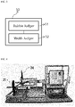
- FIG. 1 is a block diagram for describing configuration of a non-destructive inspection judgment system for aluminum pouch sealing using ultrasonic waves according to an embodiment of the present invention
- FIG. 2 is a block diagram for describing configuration of a non-destructive inspection judgment system for aluminum pouch sealing using ultrasonic waves according to another embodiment of the present invention
- FIG. 3 is a view illustrating detailed configuration of a sealing defect presence judger, which is one of configurations of the non-destructive inspection judgment system for aluminum pouch sealing using ultrasonic waves according to the other embodiment of the present invention
- FIG. 4 is a photograph schematically showing ultrasonic inspection equipment including the non-destructive inspection judgment system for aluminum pouch sealing using ultrasonic waves according to an embodiment of the present invention
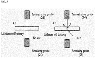
- FIG. 5 is a view for describing transmission and reception states of ultrasonic inspection equipment including a transmission probe and a receiving probe when an air part is present and when the air part is not present according to an embodiment of the present invention
- FIG. 6 is a photograph showing inspection items upon a non-destructive inspection using the ultrasonic inspection equipment according to an embodiment of the present invention
- FIG. 7 is a photograph showing cross-sections in a width direction as a result of sealing a formed pouch according to an embodiment of the present invention
- FIG. 8 is a photograph showing sealing states of mass-produced samples which are sealed and resealed according to an embodiment of the present invention
- FIG. 9 is a photograph showing a state in which a result of judging bubbles in mass-produced samples is shown on a screen of a display according to an embodiment of the present invention.
- FIG. 10 is a photograph showing a state in which a result of judging widths in mass-produced samples is shown on the screen of the display according to an embodiment of the present invention.
- the non-destructive inspection judgment system for aluminum pouch sealing using ultrasonic waves comprises a non-destructive inspection subject conveyer 10, an ultrasonic wave generator 20, an ultrasonic pulse generator-transmitter 21, a preamplifier 22, an ultrasonic pulse generation signal receiver 23, a transmission probe 24, a receiving probe 25, an interface unit 30, an ultrasonic wave generation data controller 40, a sealing defect presence judger 50, a bubble judger 51, a width judger 52, a display 60, etc.
- the non-destructive inspection judgment system for aluminum pouch sealing using ultrasonic waves comprises an ultrasonic wave generator 20 formed of probes configured to transmit and receive ultrasonic signals by generating ultrasonic waves to a non-destructive inspection subject placed on an inspection table; an interface unit 30 configured to transmit an ultrasonic signal received from the ultrasonic wave generator 20 to an ultrasonic wave generation data controller; an ultrasonic wave generation data controller 40 configured to process ultrasonic wave data received from the interface unit 30; a sealing defect presence judger 50 configured to judge, using the processed ultrasonic wave data, whether a sealing defect is present; and a display 60 configured to display a result of the judgment on a monitor, and further comprises a non-destructive inspection subject conveyer 10 configured to convey the non-destructive inspection subject to an inspection table.
- the non-destructive inspection subject conveyer 10 is configured to convey a non-destructive inspection subject to an inspection table.
- the non-destructive inspection subject is an aluminum pouch.
- the ultrasonic wave generator 20 generates ultrasonic waves to non-destructive inspection subject on an inspection table, and composed of probes which transmit and receive ultrasonic signals.
- the ultrasonic wave generator 20 comprises an ultrasonic pulse generator-transmitter 21 configured to generate ultrasonic waves and irradiate the non-destructive inspection subject with an ultrasonic signal; a preamplifier 22 configured to amplify an output of the ultrasonic signal from the ultrasonic pulse generator-transmitter 21; and an ultrasonic pulse generation signal receiver 23 configured to receive the amplified ultrasonic signal and transmit the received ultrasonic signal to the interface unit 30.
- the probes of the ultrasonic wave generator 20 comprise a set of a transmission probe 24 and a receiving probe 25.
- a frequency of each of the transmission probe and the receiving probe is 715 kHz or 800 kHz, and after a filtering value and a probe frequency are set in the ultrasonic inspection equipment so that, from a result of checking a cross-section having a sealing width length of a formed pouch, whether the formed pouch matches color regions of an ultrasonic inspection may be checked, and a probe line within an inspection section may be moved to check measurement value data, thereby allowing a "no-good" portion to be checked with visual inspection.
- the interface unit 30 configured to convey ultrasonic signals transmitted from the ultrasonic wave generator 20 to an ultrasonic wave generation data controller 40.
- the ultrasonic wave generation data controller 40 configured to process ultrasonic data transmitted from the interface unit 30.
- the sealing defect presence judger 50 configured to judge sealing defect presence by the processed ultrasonic data.
- the sealing defect presence judger 50 comprises a bubble judger 51 configured to set inspection regions at bottom, left, and right portions by moving two horizontal and vertical shafts of the inspection regions of ultrasonic inspection equipment to set judgment reference values; and a width judger 52 configured to measure sections at positions of 20 shafts at bottom, left, and right portions of the inspection regions in the ultrasonic inspection equipment and convert a length of a section having a specific output value or larger from among the measured sections into a width.
- a bubble judger 51 is placed in the sealing defect presence judger so that judgment reference values for setting inspection regions at bottom, left, and right portions by moving two horizontal and vertical shafts of ultrasonic inspection equipment are set, and thus after the non-destructive inspection, a "no-good" position may be checked from a change in the number of dots through movement of regions.
- a width judger configured to measure sections at positions of 20 shafts at bottom, left, and right portions is placed in the sealing defect presence judger 50 so that, when a length of a section having a specific output value or larger from among the measured sections is converted into a width in the ultrasonic inspection equipment, and the measured width length is shown to have specifications inferior to reference specifications, the situation is determined as "no-good".
- the display 60 configured to display the judged result on a monitor.
- non-destructive inspection items which use non-destructive inspection equipment, as illustrated in FIG. 6 , is a polybead length 3 including a sealing thickness 1, a sealing width length 2, and a polybead, and in a sealing process inspection being carried out in a sample inspection, measurement items comprise a sealing width length and a size of bubbles.
- types of sealing failure comprise leakage in which a natural electrolyte is generated and a gas leakage phenomenon occurs, and ventilation in which an electrolyte is generated due to an internal pressure of a cell and a gas leakage phenomenon occurs.
- sealing states in accordance with the types of sealing failure comprise a state in which sealing is weak, and thus boundaries of polypropylene (PP) welding surfaces at upper and lower parts of a packaged pouch are stripped, a state in which a sealing section due to side trimming is not present, and thus a PP welding part is not present, and a state in which sealing is excessive, and thus a PP layer has been stripped from an aluminum layer after a crack occurred in the polybeads of the temporarily-attached part.
- standard of tensile force is not proper, thereby standard of bubble is not proper.
- the non-destructive inspection judgment system for aluminum pouch sealing using ultrasonic waves has final goal to Inline complete automatic inspection, and thus tact time, turn table idle, judge logic, etc. should be considered, and because of this, a non-destructive inspection automatic judgment system is needed.
- a side, a bottom of a packaged sample, one site thereof after final sealing is performed, and one site thereof after degassing and resealing are performed are inspectable.
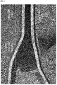
- FIG. 7 is a photograph showing cross-sections in a width direction as a result of sealing a formed pouch according to an embodiment of the present invention.
- FIG. 7 it analyzes cross-sections in width direction as a result of sealing a formed pouch through ultrasonic wave inspection result, and sealing width length of the ultrasonic wave inspection and the formed were the same as 9.5mm, a pp layer thickness should be revised, a polybead length is in peak form in a formed pouch.
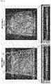
- FIG. 8 is a photograph showing sealing states of mass-produced samples which are sealed and resealed according to an embodiment of the present invention.
- sealing states of mass-produced samples which are sealed and resealed in regard of mass-produced sample 1 and mass-produced sample 2, tested in proper probe frequency is 800kHz, as shown in cross-section in the bottom were good.
- FIG. 9 is a photograph showing a state in which a result of judging bubbles in mass-produced samples is shown on a screen of a display according to an embodiment of the present invention.
- FIG. 10 is a photograph showing a state in which a result of judging widths in mass-produced samples is shown on the screen of the display according to an embodiment of the present invention.
- the non-destructive judgment system for aluminum pouch sealing using ultrasonic waves of the present invention using transmittance of ultrasonic waves, a region with a high density (sealed part) at a transmitting portion with a high transmittance is displayed in red, and a region with a low density (air part) at a transmitting portion with a low transmittance is displayed in blue, and an unsealed portion of an aluminum pouch can be detected and checked through a non-destructive inspection.
- an unsealed portion in a portion of an aluminum pouch that has been sealed through a non-destructive inspection using ultrasonic waves sets a judgment reference value since a length of a sealing width is measurable, processes measurement data, and performs automatic judgment, a sealing defect presence judger, and a display, judgment upon a non-destructive and non-contact inspection can be automated.
Landscapes
- Physics & Mathematics (AREA)
- General Physics & Mathematics (AREA)
- Health & Medical Sciences (AREA)
- Immunology (AREA)
- Biochemistry (AREA)
- General Health & Medical Sciences (AREA)
- Chemical & Material Sciences (AREA)
- Life Sciences & Earth Sciences (AREA)
- Pathology (AREA)
- Analytical Chemistry (AREA)
- Engineering & Computer Science (AREA)
- Mechanical Engineering (AREA)
- Acoustics & Sound (AREA)
- Signal Processing (AREA)
- Optics & Photonics (AREA)
- Toxicology (AREA)
- Investigating Or Analyzing Materials By The Use Of Ultrasonic Waves (AREA)
Abstract
Description
- The present invention relates to a non-destructive inspection judgment system for aluminum pouch sealing using ultrasonic waves in which, using transmittance of ultrasonic waves, a region with a high density (sealed part) at a transmitting portion with a high transmittance is displayed in red, and a region with a low density (air part) at a transmitting portion with a low transmittance is displayed in blue so that an unsealed portion of an aluminum pouch is detected and checked through a non-destructive inspection, the non-destructive inspection judgment system includes an ultrasonic wave generation data controller including processing software that detects an unsealed portion in a portion of an aluminum pouch that has been sealed through a non-destructive inspection using ultrasonic waves, sets a judgment reference value since a length of a sealing width is measurable, processes measurement data, and performs automatic judgment, a sealing defect presence judger, and a display so that judgment upon a non-destructive and non-contact inspection is automated, and a gas leakage that occurs due to weak sealing or a failure in side trimming during a process and ventilation that occurs to the outside due to an internal pressure of a cell are prevented through the non-destructive inspection for aluminum pouch sealing, a bubble judger is placed in the sealing defect presence judger so that judgment reference values for setting inspection regions at bottom, left, and right portions by moving two horizontal and vertical shafts of ultrasonic inspection equipment are set and thus, after the non-destructive inspection, a "no-good" position may be checked from a change in the number of dots through movement of regions, a width judger configured to measure sections at positions of 20 shafts at bottom, left, and right portions is placed in the sealing defect presence judger so that, when a length of a section having a specific output value or larger from among the measured sections is converted into a width in the ultrasonic inspection equipment, and the measured width length is shown to have specifications inferior to reference specifications, the situation is determined as "no-good," and whether an aluminum pouch is sealed is measured after a filtering value and a probe frequency are set in the ultrasonic inspection equipment so that, from a result of checking a cross-section having a sealing width length of a formed pouch, whether the formed pouch matches color regions of an ultrasonic inspection may be checked, and a probe line within an inspection section may be moved to check measurement value data, thereby allowing a "no-good" portion to be checked with visual inspection.
- As technology development and demand for mobile devices have increased, there has been a rapid increase in demand for secondary batteries as energy sources, and among such secondary batteries, lithium secondary batteries, which exhibit high energy density and operating potential, long cycle life, and low self-discharge rate, have been commercialized and widely used.
- In recent years, there has been a growing interest in environmental issues, and as a result, research on electric vehicles (EVs), hybrid electric vehicles (HEVs), and the like that can replace fossil-fueled vehicles such as gasoline vehicles and diesel vehicles, which are some of the main causes of air pollution, has been carried out. Although nickel-metal hydride (Ni-MH) secondary batteries are mainly used as power sources for electric vehicles (EV), hybrid electric vehicles (HEV), and the like, research on using lithium secondary batteries having high energy density, high discharge voltage and high output stability as power sources for electric vehicles (EV), hybrid electric vehicles (HEV), and the like have been vigorously carried out, and some of the lithium secondary batteries have been commercialized.
- The lithium secondary battery has a structure in which a non-aqueous electrolyte containing a lithium salt is impregnated in an electrode assembly having a porous separator interposed between a positive electrode and a negative electrode, each of which is coated with an active material on a current collector.
- The electrode assembly that has a structure consisting of a positive electrode, a separator, and a negative electrode to form a secondary battery is mainly classified into types such as a jelly-roll type (winding type), a stack type (stacked type) and a stack/folding type, which is a type in which the jelly-roll type and the stack type are combined, in accordance with a structure thereof.
- Such an electrode assembly includes an electrode tab for connection with an external terminal at each electrode. In an assembly process, such an electrode tab is coupled to an electrode lead for connection with an external terminal by welding.
- In this case, ultrasonic welding is mainly used for the welding. This is because, when resistance welding, laser welding, or the like is used, the performance of the battery may be degraded due to application of excessive energy to the electrode assembly.
- When the welding strength between the electrode tab and the electrode lead is too low in such welding, the welded portion may be separated in the process of combining a battery module or a battery pack using a battery cell. When a welding portion between a tab and a lead is separated in a battery module or a battery pack manufactured by connecting a plurality of battery cells in series or in parallel, since the entire battery pack may fail to exhibit its function, this is considered to be a serious defect.
- In order to confirm whether a failure has occurred in such ultrasonic welding, heretofore, a battery cell sample has been extracted, and whether a failure has occurred has been determined through a destructive inspection such as a shear test.
- However, in such a case, since inspection of every battery cell is not possible, there is a problem in that it is not possible to guarantee that a failure will not occur in a battery cell which is not selected as a sample for checking.
- In the ultrasonic excitation infrared thermal imaging technique, ultrasonic waves in the range of 20 to 40 kHz are incident on a test body having a failure, and some of the elastic energy of the incident ultrasonic waves is converted into thermal energy due to the thermoelastic effect at a coupling part. In this case, an infrared thermal imaging camera is synchronized with oscillated ultrasonic waves to measure temperature distribution of the test body and detect the failure.
- Ultrasonic waves generated by an ultrasonic oscillator are focused at an end of a tool horn by the tool horn, and the ultrasonic waves are transmitted to the test body due to contact between the test body and the tool horn. Since a metal horn used in a conventional ultrasonic welder is used without change as the tool horn, which is currently used in the ultrasonic excitation infrared thermal imaging technique, the tool horn is designed to maximize the ultrasonic waves being focused on the contact surface.
- However, in the ultrasonic excitation infrared thermal imaging technique, it is preferable that, in detecting a defect present in a test body, the incident ultrasonic waves are scattered throughout the test body rather than being focused on the contact surface. In addition, there is a problem that the high output ultrasonic waves at the end of the tool horn which is currently used may cause surface damage on the contact surface of the test body.
- Further, in the design of the metal tool horn, the length of the tool horn should be designed to be one half of the wavelength of the oscillating ultrasonic waves physically, and there is a problem in that such design causes an increase in the size of an ultrasonic excitation apparatus.
- In the conventional case, although it is possible to detect the unsealed portion through the non-destructive inspection on the sealed portion of the aluminum pouch and measure the length of the sealing width, there is a problem in that, since there is no software for processing measurement data, judgment has to be performed after a measurer directly checks all data.
- Thus, there is an urgent need for the development of a non-destructive inspection judgment system for aluminum pouch sealing using ultrasonic waves in which, using transmittance of ultrasonic waves, a region with a high density (sealed part) at a transmitting portion with a high transmittance is displayed in red, and a region with a low density (air part) at a transmitting portion with a low transmittance is displayed in blue so that an unsealed portion of an aluminum pouch is detected and checked through a non-destructive inspection, the non-destructive inspection judgment system includes an ultrasonic wave generation data controller including processing software that detects an unsealed portion in a portion of an aluminum pouch that has been sealed through a non-destructive inspection using ultrasonic waves, sets a judgment reference value since a length of a sealing width is measurable, processes measurement data, and performs automatic judgment, a sealing defect presence judger, and a display so that judgment upon a non-destructive and non-contact inspection is automated, and a gas leakage that occurs due to weak sealing or a failure in side trimming during a process and ventilation that occurs to the outside due to an internal pressure of a cell are prevented through the non-destructive inspection for aluminum pouch sealing, a bubble judger is placed in the sealing defect presence judger so that judgment reference values for setting inspection regions at bottom, left, and right portions by moving two horizontal and vertical shafts of ultrasonic inspection equipment are set and thus, after the non-destructive inspection, a "no-good" position may be checked from a change in the number of dots through movement of regions, and a width judger configured to measure sections at positions of 20 shafts at bottom, left, and right portions is placed in the sealing defect presence judger so that, when a length of a section having a specific output value or larger from among the measured sections is converted into a width in the ultrasonic inspection equipment, and the measured width length is shown to have specifications inferior to reference specifications, the situation is determined as "no-good."
- The present invention has been devised to solve the above-mentioned problems, and it is an aspect of the present invention to provide a non-destructive inspection judgment system for aluminum pouch sealing using ultrasonic waves in which, using transmittance of ultrasonic waves, a region with a high density (sealed part) at a transmitting portion with a high transmittance is displayed in red, and a region with a low density (air part) at a transmitting portion with a low transmittance is displayed in blue so that an unsealed portion of an aluminum pouch is detected and checked through a non-destructive inspection.
- It is another aspect of the present invention to provide a non-destructive inspection judgment system for aluminum pouch sealing using ultrasonic waves, the non-destructive inspection judgment system including an ultrasonic wave generation data controller including processing software that detects an unsealed portion in a portion of an aluminum pouch that has been sealed from a sealed portion of an aluminum pouch through a non-destructive inspection using ultrasonic waves, sets a judgment reference value since a length of a sealing width is measurable, processes measurement data, and performs automatic judgment, a sealing defect presence judger, and a display so that judgment upon a non-destructive and non-contact inspection is automated.
- It is still another aspect of the present invention to provide a non-destructive inspection judgment system for aluminum pouch sealing using ultrasonic waves in which a gas leakage that occurs due to weak sealing or a failure in side trimming during a process and ventilation that occurs to the outside due to an internal pressure of a cell are prevented through a non-destructive inspection for aluminum pouch sealing.
- It is yet another aspect of the present invention to provide a non-destructive inspection judgment system for aluminum pouch sealing using ultrasonic waves in which a bubble judger is placed in the sealing defect presence judger so that judgment reference values for setting inspection regions at bottom, left, and right portions by moving two horizontal and vertical shafts of ultrasonic inspection equipment are set and thus, after the non-destructive inspection, a "no-good" position may be checked from a change in the number of dots through movement of regions.
- It is yet another aspect of the present invention to provide a non-destructive inspection judgment system for aluminum pouch sealing using ultrasonic waves in which a width judger configured to measure sections at positions of 20 shafts at bottom, left, and right portions is placed in the sealing defect presence judger so that, when a length of a section having a specific output value or larger from among the measured sections is converted into a width in the ultrasonic inspection equipment, and the measured width length is shown to have specifications inferior to reference specifications, the situation is determined as "no-good."
- It is yet another aspect of the present invention to provide a non-destructive inspection judgment system for aluminum pouch sealing using ultrasonic waves in which whether an aluminum pouch is sealed is measured after a filtering value and a probe frequency are set in the ultrasonic inspection equipment so that, from a result of checking a cross-section having a sealing width length of a formed pouch, whether the formed pouch matches color regions of an ultrasonic inspection may be checked, and a probe line within an inspection section may be moved to check measurement value data, thereby allowing a "no-good" portion to be checked with visual inspection.
- To achieve the above aspects, a non-destructive inspection judgment system for sealing of a non-destructive inspection subject using ultrasonic waves includes an ultrasonic wave generator formed of probes configured to transmit and receive ultrasonic signals by generating ultrasonic waves to the non-destructive inspection subject placed on an inspection table, an interface unit configured to transmit an ultrasonic signal received from the ultrasonic wave generator to an ultrasonic wave generation data controller, the ultrasonic wave generation data controller configured to process ultrasonic wave data received from the interface unit, a sealing defect presence judger configured to judge, using the processed ultrasonic wave data, whether a sealing defect is present, and a display configured to display a result of the judgment on a monitor cause a result of the judgment to be displayed on a monitor of the display.
- The ultrasonic wave generator may include an ultrasonic pulse generator-transmitter configured to generate ultrasonic waves and irradiate the non-destructive inspection subject with an ultrasonic signal, a preamplifier configured to amplify an output of the ultrasonic signal from the ultrasonic pulse generator-transmitter, and an ultrasonic pulse generation signal receiver configured to receive the amplified ultrasonic signal and transmit the received ultrasonic signal to the interface unit.
- The non-destructive inspection judgment system for aluminum pouch sealing using ultrasonic waves may further include a conveyor configured to convey the non-destructive inspection subject to the inspection table.
- The probes of the ultrasonic wave generator may include a set of a transmission probe and a receiving probe.
- The sealing defect presence judger may include a bubble judger configured to set inspection regions at bottom, left, and right portions by moving two horizontal and vertical shafts of the inspection regions of ultrasonic inspection equipment to set judgment reference values, and a width judger configured to measure sections at positions of 20 shafts at bottom, left, and right portions of the inspection regions in the ultrasonic inspection equipment and convert a length of a section having a specific output value or larger from among the measured sections into a width.
- In the ultrasonic inspection equipment, a frequency of each of the transmission probe and the receiving probe may be 715 kHz or 800 kHz.
- The non-destructive inspection subject may include an aluminum pouch.
- Non-destructive inspection items may include a sealing width length and a length of a temporarily-attached part including polybeads.
- Types of sealing failures of the non-destructive inspection subject may include leakage in which a natural electrolyte is generated, and a gas leakage phenomenon occurs, and ventilation in which an electrolyte is generated due to an internal pressure of a cell of the non-destructive inspection subject, and a gas leakage phenomenon occurs.
- The non-destructive inspection subject can be a packaged pouch. Sealing states in accordance with the types of sealing failure may include a state in which sealing is weak and thus boundaries of polypropylene (PP) welding surfaces at upper and lower parts of the packaged pouch are stripped, a state in which a sealing section due to side trimming is not present and thus a PP welding part is not present, and a state in which sealing is excessive and thus a PP layer has been stripped from an aluminum layer of the packaged pouch after a crack occurred in the polybeads of the temporarily-attached part.
- Upon a sealing process inspection being carried out in a sample inspection, measurement items may include a sealing width length and a size of bubbles.
- To perform automatic judgment in a non-destructive inspection for aluminum pouch sealing, inspection of at least one of a side surface and a bottom surface of the aluminum pouch after final sealing is performed, and inspection of at least one of a side surface and a bottom surface of the aluminum pouch after degassing and resealing are performed.
- The non-destructive inspection judgment system for aluminum pouch sealing using ultrasonic waves according to the present invention has the following advantageous effects.
- First, since using transmittance of ultrasonic waves, a region with a high density (sealed part) at a transmitting portion with a high transmittance is displayed in red, and a region with a low density (air part) at a transmitting portion with a low transmittance is displayed in blue, and an unsealed portion of an aluminum pouch can be detected and checked through a non-destructive inspection.
- Second, since the non-destructive inspection judgment system includes an ultrasonic wave generation data controller including processing software that detects an unsealed portion in a portion of an aluminum pouch that has been sealed through a non-destructive inspection using ultrasonic waves, sets a judgment reference value since a length of a sealing width is measurable, processes measurement data, and performs automatic judgment, a sealing defect presence judger, and a display, judgment upon a non-destructive and non-contact inspection can be automated.
- Third, a gas leakage that occurs due to weak sealing or a failure in side trimming during a process and ventilation that occurs to the outside due to an internal pressure of a cell can be prevented through a non-destructive inspection for aluminum pouch sealing.
- Fourth, by a bubble judger placed in the sealing defect presence judger, judgment reference values for setting inspection regions at bottom, left, and right portions by moving two horizontal and vertical shafts of ultrasonic inspection equipment can be set and thus, after the non-destructive inspection, a "no-good" position can be checked from a change in the number of dots through movement of regions.
- Fifth, by a width judger, which is configured to measure sections at positions of 20 shafts at bottom, left, and right portions, placed in the sealing defect presence judger, when a length of a section having a specific output value or larger from among the measured sections is converted into a width in the ultrasonic inspection equipment, and the measured width length is shown to have specifications inferior than reference specifications, the situation can be determined as "no-good."
- Sixth, since whether an aluminum pouch is sealed is measured after a filtering value and a probe frequency are set in the ultrasonic inspection equipment, from a result of checking a cross-section having a sealing width length of a formed pouch, whether the formed pouch matches color regions of an ultrasonic inspection can be checked, and a probe line within an inspection section can be moved to check measurement value data, thereby allowing a "no-good" portion to be checked with visual inspection.
- The above and other objects, features and advantages of the present invention will become more apparent to those of ordinary skill in the art by describing exemplary embodiments thereof in detail with reference to the accompanying drawings, in which:
-
FIG. 1 is a block diagram for describing configuration of a non-destructive inspection judgment system for aluminum pouch sealing using ultrasonic waves according to an embodiment of the present invention. -
FIG. 2 is a block diagram for describing configuration of a non-destructive inspection judgment system for aluminum pouch sealing using ultrasonic waves according to another embodiment of the present invention. -
FIG. 3 is a view illustrating detailed configuration of a sealing defect presence judger, which is one of configurations of the non-destructive inspection judgment system for aluminum pouch sealing using ultrasonic waves according to the other embodiment of the present invention. -
FIG. 4 is a photograph schematically showing ultrasonic inspection equipment including the non-destructive inspection judgment system for aluminum pouch sealing using ultrasonic waves according to an embodiment of the present invention. -
FIG. 5 is a view for describing transmission and reception states of ultrasonic inspection equipment including a transmission probe and a receiving probe when an air part is present and when the air part is not present according to an embodiment of the present invention. -
FIG. 6 is a photograph showing inspection items upon a non-destructive inspection using the ultrasonic inspection equipment according to an embodiment of the present invention. -
FIG. 7 is a photograph showing cross-sections in a width direction as a result of sealing a formed pouch according to an embodiment of the present invention. -
FIG. 8 is a photograph showing sealing states of mass-produced samples which are sealed and resealed according to an embodiment of the present invention. -
FIG. 9 is a photograph showing a state in which a result of judging bubbles in mass-produced samples is shown on a screen of a display according to an embodiment of the present invention. -
FIG. 10 is a photograph showing a state in which a result of judging widths in mass-produced samples is shown on the screen of the display according to an embodiment of the present invention. - Hereinafter, exemplary embodiments of the present invention will be described with reference to the accompanying drawings. When it is determined that detailed description on known art or configuration related to the present invention may unnecessarily obscure the gist of the present invention, the detailed description thereon will be omitted. The terms to be described below are terms defined in consideration of functions in the present invention, and since the terms may vary in accordance with intentions, practices, or the like of a user or an operator, the terms should be defined on the basis of content throughout the present specification in which a non-destructive inspection judgment system for aluminum pouch sealing using ultrasonic waves, which is the present invention, is described.
-
FIG. 1 is a block diagram for describing configuration of a non-destructive inspection judgment system for aluminum pouch sealing using ultrasonic waves according to an embodiment of the present invention;FIG. 2 is a block diagram for describing configuration of a non-destructive inspection judgment system for aluminum pouch sealing using ultrasonic waves according to another embodiment of the present invention;FIG. 3 is a view illustrating detailed configuration of a sealing defect presence judger, which is one of configurations of the non-destructive inspection judgment system for aluminum pouch sealing using ultrasonic waves according to the other embodiment of the present invention;FIG. 4 is a photograph schematically showing ultrasonic inspection equipment including the non-destructive inspection judgment system for aluminum pouch sealing using ultrasonic waves according to an embodiment of the present invention;FIG. 5 is a view for describing transmission and reception states of ultrasonic inspection equipment including a transmission probe and a receiving probe when an air part is present and when the air part is not present according to an embodiment of the present invention;FIG. 6 is a photograph showing inspection items upon a non-destructive inspection using the ultrasonic inspection equipment according to an embodiment of the present invention;FIG. 7 is a photograph showing cross-sections in a width direction as a result of sealing a formed pouch according to an embodiment of the present invention;FIG. 8 is a photograph showing sealing states of mass-produced samples which are sealed and resealed according to an embodiment of the present invention;FIG. 9 is a photograph showing a state in which a result of judging bubbles in mass-produced samples is shown on a screen of a display according to an embodiment of the present invention; andFIG. 10 is a photograph showing a state in which a result of judging widths in mass-produced samples is shown on the screen of the display according to an embodiment of the present invention. - The non-destructive inspection judgment system for aluminum pouch sealing using ultrasonic waves comprises a non-destructive inspection
subject conveyer 10, anultrasonic wave generator 20, an ultrasonic pulse generator-transmitter 21, apreamplifier 22, an ultrasonic pulsegeneration signal receiver 23, atransmission probe 24, a receivingprobe 25, aninterface unit 30, an ultrasonic wavegeneration data controller 40, a sealingdefect presence judger 50, abubble judger 51, awidth judger 52, adisplay 60, etc. - As illustrated in
FIG. 1 to FIG. 6 , the non-destructive inspection judgment system for aluminum pouch sealing using ultrasonic waves comprises anultrasonic wave generator 20 formed of probes configured to transmit and receive ultrasonic signals by generating ultrasonic waves to a non-destructive inspection subject placed on an inspection table; aninterface unit 30 configured to transmit an ultrasonic signal received from theultrasonic wave generator 20 to an ultrasonic wave generation data controller; an ultrasonic wavegeneration data controller 40 configured to process ultrasonic wave data received from theinterface unit 30; a sealingdefect presence judger 50 configured to judge, using the processed ultrasonic wave data, whether a sealing defect is present; and adisplay 60 configured to display a result of the judgment on a monitor, and further comprises a non-destructive inspectionsubject conveyer 10 configured to convey the non-destructive inspection subject to an inspection table. - Moreover, functions of technical means of the non-destructive inspection judgment system for aluminum pouch sealing using ultrasonic waves are described below.
- The non-destructive inspection
subject conveyer 10 is configured to convey a non-destructive inspection subject to an inspection table. Wherein, the non-destructive inspection subject is an aluminum pouch. - The
ultrasonic wave generator 20 generates ultrasonic waves to non-destructive inspection subject on an inspection table, and composed of probes which transmit and receive ultrasonic signals. - Wherein, the
ultrasonic wave generator 20 comprises an ultrasonic pulse generator-transmitter 21 configured to generate ultrasonic waves and irradiate the non-destructive inspection subject with an ultrasonic signal; apreamplifier 22 configured to amplify an output of the ultrasonic signal from the ultrasonic pulse generator-transmitter 21; and an ultrasonic pulsegeneration signal receiver 23 configured to receive the amplified ultrasonic signal and transmit the received ultrasonic signal to theinterface unit 30. - In addition, as illustrated in
FIG. 5 , the probes of theultrasonic wave generator 20 comprise a set of atransmission probe 24 and a receivingprobe 25. - Moreover, as illustrated in
FIG. 4 , in the ultrasonic inspection equipment, a frequency of each of the transmission probe and the receiving probe is 715 kHz or 800 kHz, and after a filtering value and a probe frequency are set in the ultrasonic inspection equipment so that, from a result of checking a cross-section having a sealing width length of a formed pouch, whether the formed pouch matches color regions of an ultrasonic inspection may be checked, and a probe line within an inspection section may be moved to check measurement value data, thereby allowing a "no-good" portion to be checked with visual inspection. - The
interface unit 30 configured to convey ultrasonic signals transmitted from theultrasonic wave generator 20 to an ultrasonic wavegeneration data controller 40. - The ultrasonic wave
generation data controller 40 configured to process ultrasonic data transmitted from theinterface unit 30. - The sealing
defect presence judger 50 configured to judge sealing defect presence by the processed ultrasonic data. - Wherein, the sealing
defect presence judger 50 comprises abubble judger 51 configured to set inspection regions at bottom, left, and right portions by moving two horizontal and vertical shafts of the inspection regions of ultrasonic inspection equipment to set judgment reference values; and awidth judger 52 configured to measure sections at positions of 20 shafts at bottom, left, and right portions of the inspection regions in the ultrasonic inspection equipment and convert a length of a section having a specific output value or larger from among the measured sections into a width. - Also, a
bubble judger 51 is placed in the sealing defect presence judger so that judgment reference values for setting inspection regions at bottom, left, and right portions by moving two horizontal and vertical shafts of ultrasonic inspection equipment are set, and thus after the non-destructive inspection, a "no-good" position may be checked from a change in the number of dots through movement of regions. - Moreover, a width judger configured to measure sections at positions of 20 shafts at bottom, left, and right portions is placed in the sealing
defect presence judger 50 so that, when a length of a section having a specific output value or larger from among the measured sections is converted into a width in the ultrasonic inspection equipment, and the measured width length is shown to have specifications inferior to reference specifications, the situation is determined as "no-good". - The
display 60 configured to display the judged result on a monitor. - As described above, in the non-destructive inspection judgment system for aluminum pouch sealing using ultrasonic waves, non-destructive inspection items which use non-destructive inspection equipment, as illustrated in
FIG. 6 , is apolybead length 3 including asealing thickness 1, asealing width length 2, and a polybead, and in a sealing process inspection being carried out in a sample inspection, measurement items comprise a sealing width length and a size of bubbles. - In addition, types of sealing failure comprise leakage in which a natural electrolyte is generated and a gas leakage phenomenon occurs, and ventilation in which an electrolyte is generated due to an internal pressure of a cell and a gas leakage phenomenon occurs.
- Also, sealing states in accordance with the types of sealing failure comprise a state in which sealing is weak, and thus boundaries of polypropylene (PP) welding surfaces at upper and lower parts of a packaged pouch are stripped, a state in which a sealing section due to side trimming is not present, and thus a PP welding part is not present, and a state in which sealing is excessive, and thus a PP layer has been stripped from an aluminum layer after a crack occurred in the polybeads of the temporarily-attached part. In these cases, standard of tensile force is not proper, thereby standard of bubble is not proper.
- As described above, the non-destructive inspection judgment system for aluminum pouch sealing using ultrasonic waves has final goal to Inline complete automatic inspection, and thus tact time, turn table idle, judge logic, etc. should be considered, and because of this, a non-destructive inspection automatic judgment system is needed. In order to perform automatic judgment in a non-destructive inspection for aluminum pouch sealing, a side, a bottom of a packaged sample, one site thereof after final sealing is performed, and one site thereof after degassing and resealing are performed are inspectable.
-
FIG. 7 is a photograph showing cross-sections in a width direction as a result of sealing a formed pouch according to an embodiment of the present invention. - As illustrated in
FIG. 7 , it analyzes cross-sections in width direction as a result of sealing a formed pouch through ultrasonic wave inspection result, and sealing width length of the ultrasonic wave inspection and the formed were the same as 9.5mm, a pp layer thickness should be revised, a polybead length is in peak form in a formed pouch. -
FIG. 8 is a photograph showing sealing states of mass-produced samples which are sealed and resealed according to an embodiment of the present invention. - As illustrated in
FIG. 8 , sealing states of mass-produced samples which are sealed and resealed, in regard of mass-producedsample 1 and mass-producedsample 2, tested in proper probe frequency is 800kHz, as shown in cross-section in the bottom were good. -
FIG. 9 is a photograph showing a state in which a result of judging bubbles in mass-produced samples is shown on a screen of a display according to an embodiment of the present invention. - As illustrated in
FIG. 9 , a result of judging bubbles in mass-produced samples is shown on a screen of a display, the judged result is on the judged screen bottom and left were "OK" and right was "no good". -
FIG. 10 is a photograph showing a state in which a result of judging widths in mass-produced samples is shown on the screen of the display according to an embodiment of the present invention. - As illustrated in
FIG. 10 , a result of judging widths in mass-produced samples is shown on the screen of the display, and 20 shafts of each bottom, left, and right were measured, in judged result of width and bubble, bottom, left, and right were all judged "OK". - Therefore, the non-destructive judgment system for aluminum pouch sealing using ultrasonic waves of the present invention using transmittance of ultrasonic waves, a region with a high density (sealed part) at a transmitting portion with a high transmittance is displayed in red, and a region with a low density (air part) at a transmitting portion with a low transmittance is displayed in blue, and an unsealed portion of an aluminum pouch can be detected and checked through a non-destructive inspection. Also, an unsealed portion in a portion of an aluminum pouch that has been sealed through a non-destructive inspection using ultrasonic waves, sets a judgment reference value since a length of a sealing width is measurable, processes measurement data, and performs automatic judgment, a sealing defect presence judger, and a display, judgment upon a non-destructive and non-contact inspection can be automated.
- While this invention has been described in connection with what is presently considered to be practical exemplary embodiments, it is to be understood that the invention is not limited to the disclosed embodiments, but, on the contrary, is intended to cover various modifications and equivalent arrangements included within the spirit and scope of the appended claims.
-
- 10:
- non-destructive inspection subject conveyer
- 20:
- ultrasonic wave generator
- 21:
- ultrasonic pulse generator-transmitter
- 22:
- preamplifier
- 23:
- ultrasonic pulse generation signal receiver
- 24:
- transmission probe
- 25:
- receiving probe
- 30:
- interface unit
- 40:
- ultrasonic wave generation data controller
- 50:
- sealing defect presence judger
- 51:
- bubble judger
- 52:
- width judger
- 60:
- display
Claims (12)
- A non-destructive inspection judgment system for inspecting sealing of a non-destructive inspection subject using ultrasonic waves, the non-destructive inspection judgment system comprising:an ultrasonic wave generator formed of probes and configured to transmit and receive ultrasonic signals by generating ultrasonic waves to the non-destructive inspection subject placed on an inspection table;an interface unit configured to transmit an ultrasonic signal received from the ultrasonic wave generator to an ultrasonic wave generation data controller;the ultrasonic wave generation data controller configured to process ultrasonic wave data received from the interface unit;a sealing defect presence judger configured to judge, using the processed ultrasonic wave data, whether a sealing defect is present; anda display configured to display a result of the judgment on a monitor of the display.
- The non-destructive inspection judgment system of claim 1, wherein the ultrasonic wave generator, comprising:an ultrasonic pulse generator-transmitter configured to generate ultrasonic waves and irradiate the non-destructive inspection subject with an ultrasonic signal;a preamplifier configured to amplify an output of the ultrasonic signal from the ultrasonic pulse generator-transmitter; andan ultrasonic pulse generation signal receiver configured to receive the amplified ultrasonic signal and transmit the received ultrasonic signal to the interface unit.
- The non-destructive inspection judgment system of claim 1, wherein further comprises a non-destructive inspection subject conveyor configured to convey the non-destructive inspection subject to the inspection table.
- The non-destructive inspection judgment system of claim 1, wherein the probes of the ultrasonic wave generator comprise a set of a transmission probe and a receiving probe.
- The non-destructive inspection judgment system of claim 1, wherein the sealing defect presence judger, comprising:a bubble judger configured to set inspection regions at bottom, left, and right portions by moving two horizontal and vertical shafts of the inspection regions of ultrasonic inspection equipment to set judgment reference values; anda width judger configured to measure sections at positions of 20 shafts at bottom, left, and right portions of the inspection regions in the ultrasonic inspection equipment and convert a length of a section having a specific output value or larger from among the measured sections into a width.
- The non-destructive inspection judgment system of claim 5, wherein, in the ultrasonic inspection equipment, a frequency of each of the transmission probe and the receiving probe is 715 kHz or 800 kHz.
- The non-destructive inspection judgment system of claim 1, wherein the non-destructive inspection subject comprises an aluminum pouch.
- The non-destructive inspection judgment system of claim 1, wherein non-destructive inspection items comprise a sealing width length and a length of a temporarily-attached part including polybeads.
- The non-destructive inspection judgment system of claim 1, wherein types of sealing failures of the non-destructive inspection subject comprise leakage in which a natural electrolyte is generated and a gas leakage phenomenon occurs, and ventilation in which an electrolyte is generated due to an internal pressure of a cell of the non-destructive inspection subject and a gas leakage phenomenon occurs.
- The non-destructive inspection judgment system of claim 9,
wherein the non-destructive inspection subject is a packaged pouch, and
wherein sealing states in accordance with the types of sealing failures comprise a state in which sealing is weak and thus boundaries of polypropylene (PP) welding surfaces at upper and lower parts of the packaged pouch are stripped, a state in which a sealing section due to side trimming is not present and thus a PP welding part is not present, and a state in which sealing is excessive and thus a PP layer has been stripped from an aluminum layer of the packaged pouch after a crack occurred in polybeads of the temporarily-attached part. - The non-destructive inspection judgment system of claim 1, wherein measurement items of the inspection comprise a sealing width length and a size of bubbles.
- The non-destructive inspection judgment system of claim 1, wherein the non-destructive inspection subject is an aluminum pouch, and
wherein the non-destructive inspection judgment system performs automatic judgment in a non-destructive inspection of the sealing of the aluminum pouch, including inspecting at least one of a side and a bottom of the aluminum pouch after final sealing of the aluminum pouch is performed, and inspecting at least one of a side and a bottom of the aluminum pouch after degassing and resealing are performed.
Applications Claiming Priority (2)
| Application Number | Priority Date | Filing Date | Title |
|---|---|---|---|
| KR1020170018119A KR102141380B1 (en) | 2017-02-09 | 2017-02-09 | Nondestructive Inspection System for Aluminum Pouch Sealing Using Ultrasonic Wave |
| PCT/KR2018/001291 WO2018147586A2 (en) | 2017-02-09 | 2018-01-30 | System for non-destructively inspecting and determining sealing of aluminum pouch by using ultrasonic waves |
Publications (3)
| Publication Number | Publication Date |
|---|---|
| EP3480592A2 true EP3480592A2 (en) | 2019-05-08 |
| EP3480592A4 EP3480592A4 (en) | 2019-06-19 |
| EP3480592B1 EP3480592B1 (en) | 2025-01-01 |
Family
ID=63107028
Family Applications (1)
| Application Number | Title | Priority Date | Filing Date |
|---|---|---|---|
| EP18751271.0A Active EP3480592B1 (en) | 2017-02-09 | 2018-01-30 | Method for non-destructively inspecting and determining sealing of aluminum pouch by using ultrasonic waves |
Country Status (8)
| Country | Link |
|---|---|
| US (1) | US10921294B2 (en) |
| EP (1) | EP3480592B1 (en) |
| KR (1) | KR102141380B1 (en) |
| CN (1) | CN109477817B (en) |
| ES (1) | ES3006476T3 (en) |
| HU (1) | HUE070039T2 (en) |
| PL (1) | PL3480592T3 (en) |
| WO (1) | WO2018147586A2 (en) |
Families Citing this family (10)
| Publication number | Priority date | Publication date | Assignee | Title |
|---|---|---|---|---|
| KR102023739B1 (en) * | 2019-04-17 | 2019-09-20 | 주식회사 엘지화학 | Inner crack detection device for secondary battery using eddy current |
| KR102773409B1 (en) | 2019-08-16 | 2025-02-27 | 주식회사 엘지에너지솔루션 | An eddy current sensor with improved crack detection and eddy current inspection device comprising the same |
| KR102741369B1 (en) | 2020-02-25 | 2024-12-11 | 주식회사 엘지에너지솔루션 | Method for inspecting battery on based big data |
| FR3113529B1 (en) * | 2020-08-19 | 2023-05-26 | Commissariat Energie Atomique | Part characterization process by non-destructive testing |
| KR102565300B1 (en) | 2020-12-24 | 2023-08-10 | 이노레이 주식회사 | Testing method of secondary battery and manufacturing method of secondary battery including the same |
| JP7273786B2 (en) * | 2020-12-28 | 2023-05-15 | プライムプラネットエナジー&ソリューションズ株式会社 | FILM-TYPE BATTERY INSPECTION APPARATUS AND MANUFACTURING METHOD |
| CN112881915A (en) * | 2021-01-18 | 2021-06-01 | 恒大新能源汽车投资控股集团有限公司 | Fault identification method and device for lithium battery and computer readable storage medium |
| KR20240159324A (en) * | 2023-04-28 | 2024-11-05 | 에스케이온 주식회사 | Method and apparatus for inspecting folding part of pouch type secondary battery |
| CN118961880A (en) * | 2024-08-07 | 2024-11-15 | 天津市钰田包装制品有限公司 | Production monitoring method and system for single-spout pillow-type aseptic bags |
| CN121475567A (en) * | 2026-01-08 | 2026-02-06 | 江苏省江都水利工程管理处(江苏省南水北调水情教育中心) | An ultrasonic-based maintenance device for hydraulic cylinders of hydropower station gates |
Family Cites Families (26)
| Publication number | Priority date | Publication date | Assignee | Title |
|---|---|---|---|---|
| JPS60186753A (en) | 1984-03-05 | 1985-09-24 | Mitsubishi Heavy Ind Ltd | Inspecting device for packing container |
| JP2717550B2 (en) * | 1988-07-25 | 1998-02-18 | 日本電信電話株式会社 | Ultrasonic thickness gauge |
| CA1337830C (en) * | 1989-09-29 | 1995-12-26 | David Jarman | Ultrasonic inspection of seal integrity of bond lines in sealed containers |
| JP2912159B2 (en) | 1994-05-24 | 1999-06-28 | 株式会社神戸製鋼所 | Method and apparatus for measuring ear ratio of rolled aluminum material |
| JPH08310516A (en) | 1995-05-15 | 1996-11-26 | Nippon Tetrapack Kk | Nondestructive inspection of packaging seal |
| JP2000180146A (en) * | 1998-12-14 | 2000-06-30 | Ueda Japan Radio Co Ltd | Ultrasonic wave thickness measuring device |
| WO2001086282A1 (en) | 2000-05-11 | 2001-11-15 | Tosoh Smd, Inc. | Cleanliness evaluation in sputter targets using phase |
| US7036287B1 (en) * | 2002-07-02 | 2006-05-02 | Van Der Stahl Scientific, Inc. | Method and device for inspecting and monitoring the seal integrity of sterile packages |
| EP1585983B1 (en) | 2002-10-31 | 2008-08-13 | Martin Lehmann | Method and apparatus for manufacturing and ultrasonic testing of bonding region of sealed foodstuff containers |
| US6840108B2 (en) * | 2003-01-08 | 2005-01-11 | Packaging Technologies & Inspection Llc | Method and apparatus for airborne ultrasonic testing of package and container seals |
| US7272916B2 (en) * | 2003-07-02 | 2007-09-25 | Van Der Stahl Scientific, Inc. | Method and device for inspecting and monitoring the seal integrity of sterile packages |
| JP2005201894A (en) * | 2003-12-15 | 2005-07-28 | Showa Denko Kk | Method and apparatus for detecting flaw in aluminum alloy, and method of manufacturing aluminum alloy member and aluminum alloy continuous casting rod |
| KR20070058074A (en) | 2005-12-01 | 2007-06-07 | 삼성전자주식회사 | Handheld terminal |
| DE102007003931A1 (en) | 2007-01-26 | 2008-07-31 | Iwk Verpackungstechnik Gmbh | Method and device for checking the tightness of a filled tube in a tube filling machine |
| KR101152645B1 (en) | 2007-06-14 | 2012-06-04 | 주식회사 엘지화학 | Method of Inspecting Welding State on Welding Portion of Cell |
| KR100931370B1 (en) | 2007-11-06 | 2009-12-15 | 한국표준과학연구원 | Ultrasonic Tool Horn and Infrared Thermography Nondestructive Testing System |
| JP2010101780A (en) | 2008-10-24 | 2010-05-06 | Panasonic Ev Energy Co Ltd | Inspection method for welded spot of battery |
| KR20110015804A (en) | 2009-08-10 | 2011-02-17 | 주식회사 케이씨텍 | Air Knife Air Supply Unit |
| KR100973482B1 (en) * | 2009-12-09 | 2010-08-03 | (주)협우지여엔지니어링 | A leakage inspection apparatus using ultrasonic waves |
| KR101305255B1 (en) | 2011-02-23 | 2013-09-06 | 주식회사 엘지화학 | Methode and Device for Inspection of Intensity of Ultrasonic Welding |
| US9264198B2 (en) | 2011-02-28 | 2016-02-16 | Qualcomm Incorporated | Methods and apparatus for employing different capabilities for different duplexing modes |
| CN110261046B (en) | 2013-10-02 | 2022-08-19 | 雅马哈精密科技株式会社 | Inspection device and inspection method for sealed packaged product |
| KR101549129B1 (en) | 2013-10-23 | 2015-09-02 | 두산중공업 주식회사 | Extension tube for nondestructive examination and tube examination |
| JP2015145785A (en) | 2014-01-31 | 2015-08-13 | 株式会社コベルコ科研 | Ultrasonic microscope and ultrasonic inspection method |
| US9448208B2 (en) * | 2014-04-10 | 2016-09-20 | Packaging Technologies & Inspection Llc | System and apparatus for dual transducer ultrasonic testing of package seals |
| CN206435494U (en) | 2016-12-13 | 2017-08-25 | 广州能源检测研究院 | A kind of soft bag lithium ionic cell device for detecting sealability based on ultrasonic technique |
-
2017
- 2017-02-09 KR KR1020170018119A patent/KR102141380B1/en active Active
-
2018
- 2018-01-30 EP EP18751271.0A patent/EP3480592B1/en active Active
- 2018-01-30 US US16/325,507 patent/US10921294B2/en active Active
- 2018-01-30 PL PL18751271.0T patent/PL3480592T3/en unknown
- 2018-01-30 CN CN201880002852.0A patent/CN109477817B/en active Active
- 2018-01-30 ES ES18751271T patent/ES3006476T3/en active Active
- 2018-01-30 HU HUE18751271A patent/HUE070039T2/en unknown
- 2018-01-30 WO PCT/KR2018/001291 patent/WO2018147586A2/en not_active Ceased
Also Published As
| Publication number | Publication date |
|---|---|
| US10921294B2 (en) | 2021-02-16 |
| HUE070039T2 (en) | 2025-05-28 |
| EP3480592A4 (en) | 2019-06-19 |
| CN109477817B (en) | 2022-03-01 |
| KR102141380B1 (en) | 2020-08-05 |
| PL3480592T3 (en) | 2025-03-03 |
| US20190170703A1 (en) | 2019-06-06 |
| EP3480592B1 (en) | 2025-01-01 |
| CN109477817A (en) | 2019-03-15 |
| KR20180092445A (en) | 2018-08-20 |
| WO2018147586A2 (en) | 2018-08-16 |
| WO2018147586A3 (en) | 2018-11-15 |
| ES3006476T3 (en) | 2025-03-18 |
Similar Documents
| Publication | Publication Date | Title |
|---|---|---|
| US10921294B2 (en) | System for non-destructively inspecting and determining sealing of aluminum pouch by using ultrasonic waves | |
| KR102151175B1 (en) | Electrode damage inspection electrode damage method of pouch type secondary battery | |
| KR102290736B1 (en) | Pressure short testing device for detecting a low voltage battery cell | |
| KR102872099B1 (en) | How to inspect the welding quality of electrode tap-lead welds | |
| KR102707220B1 (en) | Non-destructive method for detecting disconnection of battery cell using pressing force | |
| KR20120096621A (en) | Methode and device for inspection of intensity of ultrasonic welding | |
| KR102072481B1 (en) | Method of Inspecting Welding State Using Pressure Gauge | |
| US9761915B2 (en) | Manufacturig method for battery | |
| KR20220020506A (en) | A system for inspecting a defect in a battery cell and a method for inspecting a defect in a battery cell | |
| US12306141B2 (en) | Welding defect inspection method | |
| JP2003045500A (en) | Battery inspection method and inspection device | |
| JP7343467B2 (en) | Battery and its manufacturing method | |
| KR102772444B1 (en) | A detecting method of welding defect | |
| JP2020072059A (en) | Secondary battery inspection method | |
| US12294066B2 (en) | Method for generating smoke in cell pack | |
| US12429525B2 (en) | Device and method for detecting internal defect of battery cell by using tdr | |
| JP2005019241A (en) | Method for producing non-aqueous electrolyte secondary battery | |
| KR20240084928A (en) | Electrode lead and busbar welding inspection method | |
| KR20230151293A (en) | Inspection method for welding quality | |
| KR20230083478A (en) | stick for welding inspection | |
| KR20240131640A (en) | Method of inspecting sealing properties of battery | |
| JP2025068319A (en) | Inspection method for battery |
Legal Events
| Date | Code | Title | Description |
|---|---|---|---|
| STAA | Information on the status of an ep patent application or granted ep patent |
Free format text: STATUS: THE INTERNATIONAL PUBLICATION HAS BEEN MADE |
|
| PUAI | Public reference made under article 153(3) epc to a published international application that has entered the european phase |
Free format text: ORIGINAL CODE: 0009012 |
|
| STAA | Information on the status of an ep patent application or granted ep patent |
Free format text: STATUS: REQUEST FOR EXAMINATION WAS MADE |
|
| 17P | Request for examination filed |
Effective date: 20190131 |
|
| AK | Designated contracting states |
Kind code of ref document: A2 Designated state(s): AL AT BE BG CH CY CZ DE DK EE ES FI FR GB GR HR HU IE IS IT LI LT LU LV MC MK MT NL NO PL PT RO RS SE SI SK SM TR |
|
| AX | Request for extension of the european patent |
Extension state: BA ME |
|
| A4 | Supplementary search report drawn up and despatched |
Effective date: 20190517 |
|
| RIC1 | Information provided on ipc code assigned before grant |
Ipc: G01N 29/04 20060101ALI20190513BHEP Ipc: G01M 3/00 20060101ALI20190513BHEP Ipc: G01N 29/24 20060101AFI20190513BHEP Ipc: G01N 29/11 20060101ALI20190513BHEP Ipc: G01N 29/06 20060101ALI20190513BHEP Ipc: B29C 65/82 20060101ALI20190513BHEP Ipc: G01N 29/36 20060101ALI20190513BHEP |
|
| DAV | Request for validation of the european patent (deleted) | ||
| DAX | Request for extension of the european patent (deleted) | ||
| STAA | Information on the status of an ep patent application or granted ep patent |
Free format text: STATUS: EXAMINATION IS IN PROGRESS |
|
| 17Q | First examination report despatched |
Effective date: 20200903 |
|
| RAP1 | Party data changed (applicant data changed or rights of an application transferred) |
Owner name: LG ENERGY SOLUTION LTD. |
|
| RAP3 | Party data changed (applicant data changed or rights of an application transferred) |
Owner name: LG ENERGY SOLUTION, LTD. |
|
| GRAP | Despatch of communication of intention to grant a patent |
Free format text: ORIGINAL CODE: EPIDOSNIGR1 |
|
| STAA | Information on the status of an ep patent application or granted ep patent |
Free format text: STATUS: GRANT OF PATENT IS INTENDED |
|
| INTG | Intention to grant announced |
Effective date: 20241009 |
|
| GRAS | Grant fee paid |
Free format text: ORIGINAL CODE: EPIDOSNIGR3 |
|
| GRAA | (expected) grant |
Free format text: ORIGINAL CODE: 0009210 |
|
| STAA | Information on the status of an ep patent application or granted ep patent |
Free format text: STATUS: THE PATENT HAS BEEN GRANTED |
|
| P01 | Opt-out of the competence of the unified patent court (upc) registered |
Free format text: CASE NUMBER: APP_59643/2024 Effective date: 20241104 |
|
| AK | Designated contracting states |
Kind code of ref document: B1 Designated state(s): AL AT BE BG CH CY CZ DE DK EE ES FI FR GB GR HR HU IE IS IT LI LT LU LV MC MK MT NL NO PL PT RO RS SE SI SK SM TR |
|
| REG | Reference to a national code |
Ref country code: GB Ref legal event code: FG4D |
|
| REG | Reference to a national code |
Ref country code: CH Ref legal event code: EP |
|
| REG | Reference to a national code |
Ref country code: DE Ref legal event code: R096 Ref document number: 602018078114 Country of ref document: DE |
|
| REG | Reference to a national code |
Ref country code: IE Ref legal event code: FG4D |
|
| REG | Reference to a national code |
Ref country code: SE Ref legal event code: TRGR |
|
| REG | Reference to a national code |
Ref country code: ES Ref legal event code: FG2A Ref document number: 3006476 Country of ref document: ES Kind code of ref document: T3 Effective date: 20250318 |
|
| REG | Reference to a national code |
Ref country code: LT Ref legal event code: MG9D |
|
| REG | Reference to a national code |
Ref country code: NL Ref legal event code: MP Effective date: 20250101 |
|
| REG | Reference to a national code |
Ref country code: HU Ref legal event code: AG4A Ref document number: E070039 Country of ref document: HU |
|
| REG | Reference to a national code |
Ref country code: AT Ref legal event code: MK05 Ref document number: 1756725 Country of ref document: AT Kind code of ref document: T Effective date: 20250101 |
|
| PG25 | Lapsed in a contracting state [announced via postgrant information from national office to epo] |
Ref country code: NL Free format text: LAPSE BECAUSE OF FAILURE TO SUBMIT A TRANSLATION OF THE DESCRIPTION OR TO PAY THE FEE WITHIN THE PRESCRIBED TIME-LIMIT Effective date: 20250101 |
|
| PG25 | Lapsed in a contracting state [announced via postgrant information from national office to epo] |
Ref country code: FI Free format text: LAPSE BECAUSE OF FAILURE TO SUBMIT A TRANSLATION OF THE DESCRIPTION OR TO PAY THE FEE WITHIN THE PRESCRIBED TIME-LIMIT Effective date: 20250101 |
|
| PG25 | Lapsed in a contracting state [announced via postgrant information from national office to epo] |
Ref country code: NO Free format text: LAPSE BECAUSE OF FAILURE TO SUBMIT A TRANSLATION OF THE DESCRIPTION OR TO PAY THE FEE WITHIN THE PRESCRIBED TIME-LIMIT Effective date: 20250401 Ref country code: IS Free format text: LAPSE BECAUSE OF FAILURE TO SUBMIT A TRANSLATION OF THE DESCRIPTION OR TO PAY THE FEE WITHIN THE PRESCRIBED TIME-LIMIT Effective date: 20250501 |
|
| PG25 | Lapsed in a contracting state [announced via postgrant information from national office to epo] |
Ref country code: HR Free format text: LAPSE BECAUSE OF FAILURE TO SUBMIT A TRANSLATION OF THE DESCRIPTION OR TO PAY THE FEE WITHIN THE PRESCRIBED TIME-LIMIT Effective date: 20250101 |
|
| PG25 | Lapsed in a contracting state [announced via postgrant information from national office to epo] |
Ref country code: LV Free format text: LAPSE BECAUSE OF FAILURE TO SUBMIT A TRANSLATION OF THE DESCRIPTION OR TO PAY THE FEE WITHIN THE PRESCRIBED TIME-LIMIT Effective date: 20250101 Ref country code: PT Free format text: LAPSE BECAUSE OF FAILURE TO SUBMIT A TRANSLATION OF THE DESCRIPTION OR TO PAY THE FEE WITHIN THE PRESCRIBED TIME-LIMIT Effective date: 20250502 |
|
| PG25 | Lapsed in a contracting state [announced via postgrant information from national office to epo] |
Ref country code: BG Free format text: LAPSE BECAUSE OF FAILURE TO SUBMIT A TRANSLATION OF THE DESCRIPTION OR TO PAY THE FEE WITHIN THE PRESCRIBED TIME-LIMIT Effective date: 20250101 Ref country code: GR Free format text: LAPSE BECAUSE OF FAILURE TO SUBMIT A TRANSLATION OF THE DESCRIPTION OR TO PAY THE FEE WITHIN THE PRESCRIBED TIME-LIMIT Effective date: 20250402 |
|
| PG25 | Lapsed in a contracting state [announced via postgrant information from national office to epo] |
Ref country code: AT Free format text: LAPSE BECAUSE OF FAILURE TO SUBMIT A TRANSLATION OF THE DESCRIPTION OR TO PAY THE FEE WITHIN THE PRESCRIBED TIME-LIMIT Effective date: 20250101 |
|
| PG25 | Lapsed in a contracting state [announced via postgrant information from national office to epo] |
Ref country code: CZ Free format text: LAPSE BECAUSE OF FAILURE TO SUBMIT A TRANSLATION OF THE DESCRIPTION OR TO PAY THE FEE WITHIN THE PRESCRIBED TIME-LIMIT Effective date: 20250101 |
|
| REG | Reference to a national code |
Ref country code: CH Ref legal event code: PL |
|
| PG25 | Lapsed in a contracting state [announced via postgrant information from national office to epo] |
Ref country code: LU Free format text: LAPSE BECAUSE OF NON-PAYMENT OF DUE FEES Effective date: 20250130 |
|
| REG | Reference to a national code |
Ref country code: DE Ref legal event code: R097 Ref document number: 602018078114 Country of ref document: DE |
|
| PG25 | Lapsed in a contracting state [announced via postgrant information from national office to epo] |
Ref country code: SM Free format text: LAPSE BECAUSE OF FAILURE TO SUBMIT A TRANSLATION OF THE DESCRIPTION OR TO PAY THE FEE WITHIN THE PRESCRIBED TIME-LIMIT Effective date: 20250101 |
|
| PG25 | Lapsed in a contracting state [announced via postgrant information from national office to epo] |
Ref country code: DK Free format text: LAPSE BECAUSE OF FAILURE TO SUBMIT A TRANSLATION OF THE DESCRIPTION OR TO PAY THE FEE WITHIN THE PRESCRIBED TIME-LIMIT Effective date: 20250101 |
|
| PG25 | Lapsed in a contracting state [announced via postgrant information from national office to epo] |
Ref country code: MC Free format text: LAPSE BECAUSE OF FAILURE TO SUBMIT A TRANSLATION OF THE DESCRIPTION OR TO PAY THE FEE WITHIN THE PRESCRIBED TIME-LIMIT Effective date: 20250101 |
|
| PG25 | Lapsed in a contracting state [announced via postgrant information from national office to epo] |
Ref country code: IT Free format text: LAPSE BECAUSE OF FAILURE TO SUBMIT A TRANSLATION OF THE DESCRIPTION OR TO PAY THE FEE WITHIN THE PRESCRIBED TIME-LIMIT Effective date: 20250101 |
|
| PG25 | Lapsed in a contracting state [announced via postgrant information from national office to epo] |
Ref country code: CH Free format text: LAPSE BECAUSE OF NON-PAYMENT OF DUE FEES Effective date: 20250131 |
|
| PG25 | Lapsed in a contracting state [announced via postgrant information from national office to epo] |
Ref country code: EE Free format text: LAPSE BECAUSE OF FAILURE TO SUBMIT A TRANSLATION OF THE DESCRIPTION OR TO PAY THE FEE WITHIN THE PRESCRIBED TIME-LIMIT Effective date: 20250101 |
|
| PG25 | Lapsed in a contracting state [announced via postgrant information from national office to epo] |
Ref country code: RO Free format text: LAPSE BECAUSE OF FAILURE TO SUBMIT A TRANSLATION OF THE DESCRIPTION OR TO PAY THE FEE WITHIN THE PRESCRIBED TIME-LIMIT Effective date: 20250101 |
|
| PG25 | Lapsed in a contracting state [announced via postgrant information from national office to epo] |
Ref country code: SK Free format text: LAPSE BECAUSE OF FAILURE TO SUBMIT A TRANSLATION OF THE DESCRIPTION OR TO PAY THE FEE WITHIN THE PRESCRIBED TIME-LIMIT Effective date: 20250101 |
|
| PLBE | No opposition filed within time limit |
Free format text: ORIGINAL CODE: 0009261 |
|
| STAA | Information on the status of an ep patent application or granted ep patent |
Free format text: STATUS: NO OPPOSITION FILED WITHIN TIME LIMIT |
|
| 26N | No opposition filed |
Effective date: 20251002 |
|
| PGFP | Annual fee paid to national office [announced via postgrant information from national office to epo] |
Ref country code: GB Payment date: 20251222 Year of fee payment: 9 |
|
| PGFP | Annual fee paid to national office [announced via postgrant information from national office to epo] |
Ref country code: FR Payment date: 20251223 Year of fee payment: 9 |
|
| PGFP | Annual fee paid to national office [announced via postgrant information from national office to epo] |
Ref country code: BE Payment date: 20251229 Year of fee payment: 9 |
|
| PGFP | Annual fee paid to national office [announced via postgrant information from national office to epo] |
Ref country code: SE Payment date: 20251223 Year of fee payment: 9 |
|
| PG25 | Lapsed in a contracting state [announced via postgrant information from national office to epo] |
Ref country code: IE Free format text: LAPSE BECAUSE OF NON-PAYMENT OF DUE FEES Effective date: 20250130 |
|
| PGFP | Annual fee paid to national office [announced via postgrant information from national office to epo] |
Ref country code: PL Payment date: 20251229 Year of fee payment: 9 |
|
| PGFP | Annual fee paid to national office [announced via postgrant information from national office to epo] |
Ref country code: HU Payment date: 20260129 Year of fee payment: 9 |
|
| PGFP | Annual fee paid to national office [announced via postgrant information from national office to epo] |
Ref country code: ES Payment date: 20260212 Year of fee payment: 9 |
|
| PGFP | Annual fee paid to national office [announced via postgrant information from national office to epo] |
Ref country code: DE Payment date: 20251222 Year of fee payment: 9 |