EP3480174B1 - Verfahren und vorrichtung zur trennung eines stabförmigen oder rohrförmigen, aus sprödem material hergestellten objekts - Google Patents
Verfahren und vorrichtung zur trennung eines stabförmigen oder rohrförmigen, aus sprödem material hergestellten objekts Download PDFInfo
- Publication number
- EP3480174B1 EP3480174B1 EP18203662.4A EP18203662A EP3480174B1 EP 3480174 B1 EP3480174 B1 EP 3480174B1 EP 18203662 A EP18203662 A EP 18203662A EP 3480174 B1 EP3480174 B1 EP 3480174B1
- Authority
- EP
- European Patent Office
- Prior art keywords
- sonotrodes
- notch
- separating
- rod
- tubular object
- Prior art date
- Legal status (The legal status is an assumption and is not a legal conclusion. Google has not performed a legal analysis and makes no representation as to the accuracy of the status listed.)
- Active
Links
- 239000000463 material Substances 0.000 title claims description 16
- 238000000034 method Methods 0.000 title claims description 15
- 239000011521 glass Substances 0.000 claims description 22
- 239000007788 liquid Substances 0.000 claims description 19
- 230000000712 assembly Effects 0.000 claims description 5
- 238000000429 assembly Methods 0.000 claims description 5
- XLYOFNOQVPJJNP-UHFFFAOYSA-N water Substances O XLYOFNOQVPJJNP-UHFFFAOYSA-N 0.000 claims description 4
- 230000015572 biosynthetic process Effects 0.000 claims description 3
- 230000000306 recurrent effect Effects 0.000 claims description 3
- 239000011324 bead Substances 0.000 description 4
- 238000000926 separation method Methods 0.000 description 4
- 239000004020 conductor Substances 0.000 description 3
- 238000004519 manufacturing process Methods 0.000 description 3
- 239000000758 substrate Substances 0.000 description 3
- 230000005540 biological transmission Effects 0.000 description 2
- 238000006073 displacement reaction Methods 0.000 description 2
- 238000007789 sealing Methods 0.000 description 2
- 239000000853 adhesive Substances 0.000 description 1
- 230000001070 adhesive effect Effects 0.000 description 1
- 230000006835 compression Effects 0.000 description 1
- 238000007906 compression Methods 0.000 description 1
- 239000005357 flat glass Substances 0.000 description 1
- 238000009413 insulation Methods 0.000 description 1
- 239000002245 particle Substances 0.000 description 1
- 230000002093 peripheral effect Effects 0.000 description 1
- 239000007787 solid Substances 0.000 description 1
- 239000002195 soluble material Substances 0.000 description 1
- 238000002604 ultrasonography Methods 0.000 description 1
- 238000005406 washing Methods 0.000 description 1
- 230000003313 weakening effect Effects 0.000 description 1
Images

Classifications
-
- C—CHEMISTRY; METALLURGY
- C03—GLASS; MINERAL OR SLAG WOOL
- C03B—MANUFACTURE, SHAPING, OR SUPPLEMENTARY PROCESSES
- C03B33/00—Severing cooled glass
- C03B33/06—Cutting or splitting glass tubes, rods, or hollow products
Definitions
- a method for separating a rod-like or tubular object made of a brittle material, particularly glass in which at first at least one circumferential notch is made on the surface of the object, and then the fixed object is acted on by a force impulse or impulses.
- a device for separating a rod-like or tubular object made of a brittle material, particularly glass, which has been previously provided with circumferential notches at points where the object is to be separated the device further comprising a source of impulsive force with an optional output and a clamping device for fastening the object relative to the impulsive force source.
- Document DE102005054669A1 primarily deals with the cutting of glass panes.
- a straight notch is cut by a cutting wheel, needle, or laser at the point where the pane is to be divided.
- An ultrasonic oscillator is brought into contact with the glass near the notch and is guided at a frequency of 20 to 30 kHz on the glass along the notch, thereby separating the glass in the notch region.
- the document also discloses an alternative method, namely a method of dividing a glass tube in whose surface the notch has been made previously. The contact surface of the ultrasound oscillator is then guided around the circumference of the tube in the notch region.
- this method is technically and economically unusable for dividing small diameter tubes, for example, in the production of glass beads.
- Document JP2009149482A discloses a method of cutting a glass tube by the use of an ultrasonic vibration cutter. The cutter is pressed against the desired cutting location in the outer peripheral surface of a glass tube in order to scribe the tube and in a second step the tube is cut by the drive of said ultrasonic vibrator.
- Document WO2014186999A1 discloses a method of cutting flat glass substrates to form a cutting gap.
- the cutting gap is in contact with the ultrasonic wave transmission medium.
- An ultrasonic generator is disposed above the cut glass substrate reaching the splitting region.
- the sonotrode is adjusted to have an appropriate output power and to emit an ultrasonic wave, which is transmitted through a transmission medium.
- the transfer medium is water.
- the aim of the invention is therefore to eliminate the drawbacks of the background art and propose a solution which would be economical, especially for glass tubes of small diameters, and which would enable to produce the resulting elements formed by division with the desired length and smooth surface of their end faces.
- the aim of the invention is achieved by a method for separating a rod-like or tubular object made of a brittle material, whose principle consists in that in order to separate a section of the object to be divided, at least the surface area of a circumferential notch is placed with a radial clearance between the ends of sonotrodes arranged around the entire circumference of the notch, whereby the ends of the sonotrodes and the circumference of the notch are in contact with the working liquid, whereupon acoustic waves are transmitted to the notch from each sonotrode.
- the separated object at this point is loaded by a tensile stress greater than the limit tensile strength of the material of the object to be separated.
- all sonotrodes are excited by harmonic tension having a frequency equal to the natural frequency of the sonotrodes, which causes recurrent formation of cavitations in the notch region and their subsequent implosions.
- This method of separating a tube results in creating high quality surfaces of the preform faces, since an impact acts simultaneously on the entire circumference of the tube and the applied forces are uniformly distributed around the entire circumference.
- the aim of the invention is also achieved by a device for separating a rod-like or tubular object made of a brittle material, whose principle is that the source of impulsive force is formed by a ring of radially arranged assemblies, which always comprise an ultrasonic oscillator and an adjoining sonotrode, whereby the active ends of the sonotrodes surround the entire circumference of the notch in the surface of the separated object at a distance determined by the circumferential radial gap, whereby at least the space of the radial gap is filled with the working liquid, through which contact is established between the active ends of the sonotrodes and the circumferential notch.
- the space of the circumferential radial gap is sealed with respect to the lateral surfaces of the sonotrodes and other components of the impulsive force source, whereby the lateral surfaces of the sonotrodes and other components of the impulsive force source are arranged in the space of the dry chamber.
- the space of the radial gap between the ends of the sonotrodes and the tube surface is connected to a working liquid tank.
- FIG. 1 shows an oblique view of the separating device with an inserted tube
- Fig. 2 shows a front view of the separating device of Fig. 1 in the direction of the axis of the tube, the separating device being located in a housing with working liquid
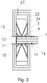
- Fig. 3 is a sectional view A-A of Fig. 2 taken along the longitudinal axis of the tube.
- the device according to the invention for separating a tube 1 made of a brittle material consists of two basic parts.
- the first part of the device which is not a subject-matter of the invention and is not shown, comprises a cutting means, for example, a known device for disrupting the surface of the glass tube by making at least one circumferential notch 11 in the outer surface of the tube 1 .
- a cutting means for example, a known device for disrupting the surface of the glass tube by making at least one circumferential notch 11 in the outer surface of the tube 1 .
- This is performed by any of the known cutting tools, such as a cutting wheel, needle, laser, etc. It is important for the notches to be spaced at the same mutual distances and to have the same shape, so that they will create the same weakening of the cross section of the tube wall.
- the circumferential notch is a region with considerably lower strength compared to the uninterrupted section of the tube, therefore the fracture and separation of the section of the tube 1 is performed in a controlled manner in the region of the notch.
- the separated sections of the tube 1 are hereinafter referred to as "preform".
- the second part of the device shown in Fig. 1 is the actual active means for breaking off the preform 12 from the remaining section of the tube 1 , which is the source 2 of impulsive force.
- the source 2 of impulsive force has the shape of a flat ring, the outer circumference of which in an exemplary embodiment is substantially an octagon formed by quadrangular supports of the radial pyramidal assemblies 21 surrounding the circumference of the tube 1 and tapered towards the tube. Between the adjacent surfaces of the individual assemblies 21 there are gaps 22 , and therefore the assemblies 21 do not touch one another.
- An ultrasonic oscillator 23 with a piezoelectric element is arranged in the circumferential part of each assembly 21 .
- the ultrasonic oscillator 23 is joined by a tapered sonotrode 24 .
- the ends of the sonotrodes 24 form a short cylindrical opening, or an octagonal opening, which surrounds the outer circumference of the separated tube 1 .
- the ultrasonic oscillators 23 are connected by the schematically represented conductors 26 to the supply lead 27 of the electric current and an unillustrated control system.
- the contact of the sonotrodes 24 with the separated tube 1 is in the described embodiment established by a working liquid, which is usually water. It is the end of the sonotrodes 24 facing the separated tube 1 and the surface of the tube 1 in the region of the notch 11 that is in contact with the working liquid, as shown in Fig. 1 . At the same time, however, it is necessary that the other surfaces of the sonotrodes 24 , the ultrasonic oscillators 23 and the electric conductors 26 , 27 , through which the sonotrodes 24 are connected to the source of power supply, are isolated from the liquid.
- an active means more specifically, the source 2 of impulsive force in the section of the tube 1 with the circumferential notch 11 , in which the preform 12 is to be broken off, is mounted in the liquid tank 3 .
- the required height of the insulation is solved, for example, by means of an inner dry chamber 4 insulated by a schematically illustrated sealing 13 of the gaps between the sonotrodes 24 and other means (not shown).
- the tube 1 is placed in the required position in an unillustrated guide means 14 , which at the same time allows filling up the space in the notch 11 region with a liquid after the displacement of the tube 1 .
- the device according to the invention enables to separate the preforms 12 in two ways.
- pulsating stress is fed to the ultrasonic oscillators 23 , which causes all the sonotrodes 24 to transmit to the liquid an acoustic wave focused by the shape of the outlet portion of the sonotrodes 24 to the region of the notch 11 practically throughout its circumference.
- a pressure wave to the sides of the notch 11 a tensile stress concentration occurs at its bottom, exceeding the limit tensile strength of the tube 1 material. As a result, the corresponding preform 12 is broken off.
- harmonic stress having a frequency equal to the natural frequency of the sonotrodes 24 is fed to the ultrasonic oscillators 23 , thereby generating acoustic waves of high intensity in the liquid. This causes recurrent formation of cavitations in the vicinity of the notch 11 . During their implosion, strong compression strokes occur in the vicinity of the notch 11 , which, as in the first case, causes the respective preform 12 to be broken off.
Landscapes
- Chemical & Material Sciences (AREA)
- Engineering & Computer Science (AREA)
- Materials Engineering (AREA)
- Organic Chemistry (AREA)
- Re-Forming, After-Treatment, Cutting And Transporting Of Glass Products (AREA)
- Perforating, Stamping-Out Or Severing By Means Other Than Cutting (AREA)
Claims (9)
- Verfahren zur Teilung eines stab- oder rohrförmigen Gegenstandes, der aus einem zerbrechlichen Material, insbesondere aus Glas, gebildet wird, bei dem auf der Oberfläche des Gegenstandes zuerst in der bestimmten Stelle mindestens ein Umfangsritz (11) gebildet wird, wonach auf den befestigten Gegenstand mit einem Kraftimpuls oder Kraftimpulsen gewirkt wird, dadurch gekennzeichnet, dass zur Teilung des Teiles des zu teilenden Gegenstandes mindestens die Oberflächenfläche des Umfangsritzes (11) mit einem Radialspiel zwischen die Enden der Sonotroden (24) angebracht wird, die um den ganzen Umfang des Ritzes (11) herum angeordnet sind, wobei die Enden der Sonotroden (24) und der Umfang des Ritzes (11) mit der Arbeitsflüssigkeit im Kontakt stehen, wonach aus jeder Sonotrode (24) eine akustische Wellenbewegung in die Stelle des Ritzes (11) gesendet wird, wodurch der zu teilende Gegenstand in dieser Stelle mit einer Zugspannung belastet wird, die größer als die Zugfestigkeitsgrenze des Materials des zu teilenden Gegenstandes ist.
- Verfahren zur Teilung eines stab- oder rohrförmigen Gegenstandes, der aus einem zerbrechlichen Material gebildet wird, nach dem Anspruch 1, dadurch gekennzeichnet, dass zum Hervorrufen der akustischen Wellenbewegung alle Sonotroden (24) mit der Spannung eines Impulscharakters synchron erregt werden, die sich in die Stelle des Ritzes (11) konzentriert.
- Verfahren zur Teilung eines stab- oder rohrförmigen Gegenstandes, der aus einem zerbrechlichen Material gebildet wird, nach dem Anspruch 1, dadurch gekennzeichnet, dass zum Hervorrufen der akustischen Wellenbewegung alle Sonotroden (24) mit harmonischer Spannung mit solcher Frequenz erregt werden, die der eigenen Frequenz von Sonotroden gleich ist, wodurch in der Stelle des Ritzes (11) in der Flüssigkeit eine wiederholte Entstehung von Kavitationshohlräumen und ihre nachfolgende Implosion hervorgerufen werden.
- Einrichtung zur Teilung des stab- oder rohrförmigen Gegenstandes, der aus einem zerbrechlichen Material, insbesondere aus Glas, gebildet wird, der im Voraus Umfangsritze (11) in den Stellen aufweist, in denen der jeweilige Gegenstand geteilt werden soll, die eine Quelle (2) der Impulskraft mit einer wählbaren Leistung und ein Aufnahmemittel (14) zur Lagerung des zu teilenden Gegenstandes in Bezug auf die Quelle (2) der Impulskraft aufweist, dadurch gekennzeichnet, dass die Quelle (2) der Impulskraft durch einen Ring der radial angeordneten Gruppen (21) gebildet wird, die immer einen Ultraschalloszillator (23) und die daran anschließende Sonotrode (24) aufweisen, wobei die aktiven Enden der Sonotroden (24) in dem durch den radialen Umfangsspalt (25) gegebenen Abstand den ganzen Umfang des Ritzes (11) in der Oberfläche des zu teilenden Gegenstandes umschließen, wobei mindestens der Raum des radialen Umfangsspaltes (25) mit einer Arbeitsflüssigkeit ausgefüllt ist, durch die der Kontakt zwischen aktiven Enden der Sonotroden (24) und dem Umfangsritz (11) vermittelt wird.
- Einrichtung zur Teilung des stab- oder rohrförmigen Gegenstandes nach dem Anspruch 4, dadurch gekennzeichnet, dass der Raum des radialen Umfangsspaltes (25) in Bezug auf die Seitenflächen der Sonotroden (24) und weitere Teile der Quelle (2) der Impulskraft abgedichtet ist.
- Einrichtung zur Teilung des stab- oder rohrförmigen Gegenstandes nach dem Anspruch 4 oder 5, dadurch gekennzeichnet, dass die Seitenflächen der Sonotroden (24) und weitere Teile der Quelle (2) der Impulskraft im Raum der Trockenkammer (4) angeordnet sind.
- Einrichtung zur Teilung des stab- oder rohrförmigen Gegenstandes nach einem der Ansprüche 4 bis 6, dadurch gekennzeichnet, dass der Raum des Radialspaltes (25) an den Behälter der Arbeitsflüssigkeit angeschlossen ist.
- Einrichtung zur Teilung des stab- oder rohrförmigen Gegenstandes nach dem Anspruch 7, dadurch gekennzeichnet, dass der Behälter der Arbeitsflüssigkeit die Trockenkammer (3) umschließt.
- Einrichtung zur Teilung des stab- oder rohrförmigen Gegenstandes nach einem der Ansprüche 4 bis 8, dadurch gekennzeichnet, dass die Arbeitsflüssigkeit Wasser ist.
Applications Claiming Priority (1)
| Application Number | Priority Date | Filing Date | Title |
|---|---|---|---|
| CZ2017-701A CZ307547B6 (cs) | 2017-11-01 | 2017-11-01 | Způsob a zařízení k dělení tyčovitého nebo trubkovitého předmětu vytvořeného z křehkého materiálu |
Publications (2)
| Publication Number | Publication Date |
|---|---|
| EP3480174A1 EP3480174A1 (de) | 2019-05-08 |
| EP3480174B1 true EP3480174B1 (de) | 2019-12-11 |
Family
ID=64269305
Family Applications (1)
| Application Number | Title | Priority Date | Filing Date |
|---|---|---|---|
| EP18203662.4A Active EP3480174B1 (de) | 2017-11-01 | 2018-10-31 | Verfahren und vorrichtung zur trennung eines stabförmigen oder rohrförmigen, aus sprödem material hergestellten objekts |
Country Status (2)
| Country | Link |
|---|---|
| EP (1) | EP3480174B1 (de) |
| CZ (1) | CZ307547B6 (de) |
Family Cites Families (3)
| Publication number | Priority date | Publication date | Assignee | Title |
|---|---|---|---|---|
| JP4951494B2 (ja) * | 2007-12-21 | 2012-06-13 | 東ソー・クォーツ株式会社 | ガラス管の切断方法 |
| CN103288340B (zh) * | 2013-05-20 | 2016-08-10 | 深圳市华星光电技术有限公司 | 玻璃基板的切割裂片装置及其切割裂片方法 |
| CN105217944B (zh) * | 2015-10-28 | 2018-06-05 | 京东方科技集团股份有限公司 | 一种切割裂片装置 |
-
2017
- 2017-11-01 CZ CZ2017-701A patent/CZ307547B6/cs not_active IP Right Cessation
-
2018
- 2018-10-31 EP EP18203662.4A patent/EP3480174B1/de active Active
Non-Patent Citations (1)
| Title |
|---|
| None * |
Also Published As
| Publication number | Publication date |
|---|---|
| CZ2017701A3 (cs) | 2018-11-21 |
| CZ307547B6 (cs) | 2018-11-21 |
| EP3480174A1 (de) | 2019-05-08 |
Similar Documents
| Publication | Publication Date | Title |
|---|---|---|
| US9649722B2 (en) | Ultrasound-assisted water-confined laser micromachining | |
| JP6227593B2 (ja) | 複数のワイヤを導電結合するための方法およびアセンブリ | |
| CN106142537B (zh) | 超声处理装置和用于其的横向密封超声焊极 | |
| US11247294B2 (en) | Device for welding components by means of ultrasound | |
| CA2812468C (en) | Ultrasonic vibration unit | |
| US20180354003A1 (en) | Device and method for deburring components ultrasound | |
| US9993970B2 (en) | Cross seam joining device for joining a sealing seam for a flexible packaging | |
| JP6212573B2 (ja) | 超音波溶接機用の超音波コレットホーン | |
| TW201726268A (zh) | 超音波放大器 | |
| EP3480174A1 (de) | Verfahren und vorrichtung zur trennung eines stabförmigen oder rohrförmigen, aus sprödem material hergestellten objekts | |
| JP6312476B2 (ja) | レーザ切断装置 | |
| US6196087B1 (en) | Apparatus and method for removing an insulation cover from an insulation covered wire at intermediate portion | |
| US20030017578A1 (en) | Apparatus for transferring molecules into cells | |
| KR102307418B1 (ko) | 유리 예비성형체의 형성 방법 | |
| JP2014172083A (ja) | ブースタホーン及びブースタホーンを用いた超音波溶着装置 | |
| CN105666546A (zh) | 一种高频纵扭复合振动海绵取条装置及应用 | |
| US4485286A (en) | Multi-vibrator head EDM method and apparatus | |
| US10072525B2 (en) | Gas turbine engine | |
| US9449595B2 (en) | Sonotrode with processing channel | |
| JP4951494B2 (ja) | ガラス管の切断方法 | |
| CN109314360A (zh) | 用于压接连接元件的装置和方法、以及压接连接 | |
| EP3480172A1 (de) | Verfahren und vorrichtung zum trennen eines stabförmigen oder rohrförmigen objekts aus einem spröden material | |
| CN105690444A (zh) | 一种高频纵扭复合振动海绵打孔工作台及应用 | |
| CN105666575A (zh) | 一种高频振动海绵取条装置及应用 | |
| US20160144989A1 (en) | Separating tool of a joining device for flexible packagings |
Legal Events
| Date | Code | Title | Description |
|---|---|---|---|
| PUAI | Public reference made under article 153(3) epc to a published international application that has entered the european phase |
Free format text: ORIGINAL CODE: 0009012 |
|
| STAA | Information on the status of an ep patent application or granted ep patent |
Free format text: STATUS: THE APPLICATION HAS BEEN PUBLISHED |
|
| STAA | Information on the status of an ep patent application or granted ep patent |
Free format text: STATUS: REQUEST FOR EXAMINATION WAS MADE |
|
| AK | Designated contracting states |
Kind code of ref document: A1 Designated state(s): AL AT BE BG CH CY CZ DE DK EE ES FI FR GB GR HR HU IE IS IT LI LT LU LV MC MK MT NL NO PL PT RO RS SE SI SK SM TR |
|
| AX | Request for extension of the european patent |
Extension state: BA ME |
|
| 17P | Request for examination filed |
Effective date: 20190423 |
|
| RBV | Designated contracting states (corrected) |
Designated state(s): AL AT BE BG CH CY CZ DE DK EE ES FI FR GB GR HR HU IE IS IT LI LT LU LV MC MK MT NL NO PL PT RO RS SE SI SK SM TR |
|
| GRAP | Despatch of communication of intention to grant a patent |
Free format text: ORIGINAL CODE: EPIDOSNIGR1 |
|
| STAA | Information on the status of an ep patent application or granted ep patent |
Free format text: STATUS: GRANT OF PATENT IS INTENDED |
|
| INTG | Intention to grant announced |
Effective date: 20190902 |
|
| GRAS | Grant fee paid |
Free format text: ORIGINAL CODE: EPIDOSNIGR3 |
|
| GRAA | (expected) grant |
Free format text: ORIGINAL CODE: 0009210 |
|
| STAA | Information on the status of an ep patent application or granted ep patent |
Free format text: STATUS: THE PATENT HAS BEEN GRANTED |
|
| AK | Designated contracting states |
Kind code of ref document: B1 Designated state(s): AL AT BE BG CH CY CZ DE DK EE ES FI FR GB GR HR HU IE IS IT LI LT LU LV MC MK MT NL NO PL PT RO RS SE SI SK SM TR |
|
| REG | Reference to a national code |
Ref country code: GB Ref legal event code: FG4D |
|
| REG | Reference to a national code |
Ref country code: CH Ref legal event code: EP |
|
| REG | Reference to a national code |
Ref country code: AT Ref legal event code: REF Ref document number: 1212018 Country of ref document: AT Kind code of ref document: T Effective date: 20191215 |
|
| REG | Reference to a national code |
Ref country code: DE Ref legal event code: R096 Ref document number: 602018001578 Country of ref document: DE |
|
| REG | Reference to a national code |
Ref country code: IE Ref legal event code: FG4D |
|
| REG | Reference to a national code |
Ref country code: DE Ref legal event code: R082 Ref document number: 602018001578 Country of ref document: DE Representative=s name: PATENTANWAELTE CANZLER & BERGMEIER PARTNERSCHA, DE |
|
| REG | Reference to a national code |
Ref country code: NL Ref legal event code: MP Effective date: 20191211 |
|
| REG | Reference to a national code |
Ref country code: LT Ref legal event code: MG4D |
|
| PG25 | Lapsed in a contracting state [announced via postgrant information from national office to epo] |
Ref country code: SE Free format text: LAPSE BECAUSE OF FAILURE TO SUBMIT A TRANSLATION OF THE DESCRIPTION OR TO PAY THE FEE WITHIN THE PRESCRIBED TIME-LIMIT Effective date: 20191211 Ref country code: LV Free format text: LAPSE BECAUSE OF FAILURE TO SUBMIT A TRANSLATION OF THE DESCRIPTION OR TO PAY THE FEE WITHIN THE PRESCRIBED TIME-LIMIT Effective date: 20191211 Ref country code: FI Free format text: LAPSE BECAUSE OF FAILURE TO SUBMIT A TRANSLATION OF THE DESCRIPTION OR TO PAY THE FEE WITHIN THE PRESCRIBED TIME-LIMIT Effective date: 20191211 Ref country code: BG Free format text: LAPSE BECAUSE OF FAILURE TO SUBMIT A TRANSLATION OF THE DESCRIPTION OR TO PAY THE FEE WITHIN THE PRESCRIBED TIME-LIMIT Effective date: 20200311 Ref country code: LT Free format text: LAPSE BECAUSE OF FAILURE TO SUBMIT A TRANSLATION OF THE DESCRIPTION OR TO PAY THE FEE WITHIN THE PRESCRIBED TIME-LIMIT Effective date: 20191211 Ref country code: NO Free format text: LAPSE BECAUSE OF FAILURE TO SUBMIT A TRANSLATION OF THE DESCRIPTION OR TO PAY THE FEE WITHIN THE PRESCRIBED TIME-LIMIT Effective date: 20200311 Ref country code: GR Free format text: LAPSE BECAUSE OF FAILURE TO SUBMIT A TRANSLATION OF THE DESCRIPTION OR TO PAY THE FEE WITHIN THE PRESCRIBED TIME-LIMIT Effective date: 20200312 |
|
| PG25 | Lapsed in a contracting state [announced via postgrant information from national office to epo] |
Ref country code: RS Free format text: LAPSE BECAUSE OF FAILURE TO SUBMIT A TRANSLATION OF THE DESCRIPTION OR TO PAY THE FEE WITHIN THE PRESCRIBED TIME-LIMIT Effective date: 20191211 Ref country code: HR Free format text: LAPSE BECAUSE OF FAILURE TO SUBMIT A TRANSLATION OF THE DESCRIPTION OR TO PAY THE FEE WITHIN THE PRESCRIBED TIME-LIMIT Effective date: 20191211 |
|
| PG25 | Lapsed in a contracting state [announced via postgrant information from national office to epo] |
Ref country code: AL Free format text: LAPSE BECAUSE OF FAILURE TO SUBMIT A TRANSLATION OF THE DESCRIPTION OR TO PAY THE FEE WITHIN THE PRESCRIBED TIME-LIMIT Effective date: 20191211 |
|
| PG25 | Lapsed in a contracting state [announced via postgrant information from national office to epo] |
Ref country code: RO Free format text: LAPSE BECAUSE OF FAILURE TO SUBMIT A TRANSLATION OF THE DESCRIPTION OR TO PAY THE FEE WITHIN THE PRESCRIBED TIME-LIMIT Effective date: 20191211 Ref country code: NL Free format text: LAPSE BECAUSE OF FAILURE TO SUBMIT A TRANSLATION OF THE DESCRIPTION OR TO PAY THE FEE WITHIN THE PRESCRIBED TIME-LIMIT Effective date: 20191211 Ref country code: ES Free format text: LAPSE BECAUSE OF FAILURE TO SUBMIT A TRANSLATION OF THE DESCRIPTION OR TO PAY THE FEE WITHIN THE PRESCRIBED TIME-LIMIT Effective date: 20191211 Ref country code: EE Free format text: LAPSE BECAUSE OF FAILURE TO SUBMIT A TRANSLATION OF THE DESCRIPTION OR TO PAY THE FEE WITHIN THE PRESCRIBED TIME-LIMIT Effective date: 20191211 Ref country code: CZ Free format text: LAPSE BECAUSE OF FAILURE TO SUBMIT A TRANSLATION OF THE DESCRIPTION OR TO PAY THE FEE WITHIN THE PRESCRIBED TIME-LIMIT Effective date: 20191211 Ref country code: PT Free format text: LAPSE BECAUSE OF FAILURE TO SUBMIT A TRANSLATION OF THE DESCRIPTION OR TO PAY THE FEE WITHIN THE PRESCRIBED TIME-LIMIT Effective date: 20200506 |
|
| PG25 | Lapsed in a contracting state [announced via postgrant information from national office to epo] |
Ref country code: SK Free format text: LAPSE BECAUSE OF FAILURE TO SUBMIT A TRANSLATION OF THE DESCRIPTION OR TO PAY THE FEE WITHIN THE PRESCRIBED TIME-LIMIT Effective date: 20191211 Ref country code: SM Free format text: LAPSE BECAUSE OF FAILURE TO SUBMIT A TRANSLATION OF THE DESCRIPTION OR TO PAY THE FEE WITHIN THE PRESCRIBED TIME-LIMIT Effective date: 20191211 Ref country code: IS Free format text: LAPSE BECAUSE OF FAILURE TO SUBMIT A TRANSLATION OF THE DESCRIPTION OR TO PAY THE FEE WITHIN THE PRESCRIBED TIME-LIMIT Effective date: 20200411 |
|
| REG | Reference to a national code |
Ref country code: DE Ref legal event code: R097 Ref document number: 602018001578 Country of ref document: DE |
|
| REG | Reference to a national code |
Ref country code: AT Ref legal event code: MK05 Ref document number: 1212018 Country of ref document: AT Kind code of ref document: T Effective date: 20191211 |
|
| PLBE | No opposition filed within time limit |
Free format text: ORIGINAL CODE: 0009261 |
|
| STAA | Information on the status of an ep patent application or granted ep patent |
Free format text: STATUS: NO OPPOSITION FILED WITHIN TIME LIMIT |
|
| PG25 | Lapsed in a contracting state [announced via postgrant information from national office to epo] |
Ref country code: DK Free format text: LAPSE BECAUSE OF FAILURE TO SUBMIT A TRANSLATION OF THE DESCRIPTION OR TO PAY THE FEE WITHIN THE PRESCRIBED TIME-LIMIT Effective date: 20191211 |
|
| 26N | No opposition filed |
Effective date: 20200914 |
|
| PG25 | Lapsed in a contracting state [announced via postgrant information from national office to epo] |
Ref country code: AT Free format text: LAPSE BECAUSE OF FAILURE TO SUBMIT A TRANSLATION OF THE DESCRIPTION OR TO PAY THE FEE WITHIN THE PRESCRIBED TIME-LIMIT Effective date: 20191211 |
|
| PG25 | Lapsed in a contracting state [announced via postgrant information from national office to epo] |
Ref country code: IT Free format text: LAPSE BECAUSE OF FAILURE TO SUBMIT A TRANSLATION OF THE DESCRIPTION OR TO PAY THE FEE WITHIN THE PRESCRIBED TIME-LIMIT Effective date: 20191211 |
|
| PG25 | Lapsed in a contracting state [announced via postgrant information from national office to epo] |
Ref country code: PL Free format text: LAPSE BECAUSE OF FAILURE TO SUBMIT A TRANSLATION OF THE DESCRIPTION OR TO PAY THE FEE WITHIN THE PRESCRIBED TIME-LIMIT Effective date: 20191211 Ref country code: SI Free format text: LAPSE BECAUSE OF FAILURE TO SUBMIT A TRANSLATION OF THE DESCRIPTION OR TO PAY THE FEE WITHIN THE PRESCRIBED TIME-LIMIT Effective date: 20191211 |
|
| PG25 | Lapsed in a contracting state [announced via postgrant information from national office to epo] |
Ref country code: LU Free format text: LAPSE BECAUSE OF NON-PAYMENT OF DUE FEES Effective date: 20201031 Ref country code: MC Free format text: LAPSE BECAUSE OF FAILURE TO SUBMIT A TRANSLATION OF THE DESCRIPTION OR TO PAY THE FEE WITHIN THE PRESCRIBED TIME-LIMIT Effective date: 20191211 |
|
| REG | Reference to a national code |
Ref country code: BE Ref legal event code: MM Effective date: 20201031 |
|
| PG25 | Lapsed in a contracting state [announced via postgrant information from national office to epo] |
Ref country code: FR Free format text: LAPSE BECAUSE OF NON-PAYMENT OF DUE FEES Effective date: 20201031 |
|
| PG25 | Lapsed in a contracting state [announced via postgrant information from national office to epo] |
Ref country code: BE Free format text: LAPSE BECAUSE OF NON-PAYMENT OF DUE FEES Effective date: 20201031 |
|
| PG25 | Lapsed in a contracting state [announced via postgrant information from national office to epo] |
Ref country code: IE Free format text: LAPSE BECAUSE OF NON-PAYMENT OF DUE FEES Effective date: 20201031 |
|
| REG | Reference to a national code |
Ref country code: CH Ref legal event code: PL |
|
| PG25 | Lapsed in a contracting state [announced via postgrant information from national office to epo] |
Ref country code: TR Free format text: LAPSE BECAUSE OF FAILURE TO SUBMIT A TRANSLATION OF THE DESCRIPTION OR TO PAY THE FEE WITHIN THE PRESCRIBED TIME-LIMIT Effective date: 20191211 Ref country code: MT Free format text: LAPSE BECAUSE OF FAILURE TO SUBMIT A TRANSLATION OF THE DESCRIPTION OR TO PAY THE FEE WITHIN THE PRESCRIBED TIME-LIMIT Effective date: 20191211 Ref country code: CY Free format text: LAPSE BECAUSE OF FAILURE TO SUBMIT A TRANSLATION OF THE DESCRIPTION OR TO PAY THE FEE WITHIN THE PRESCRIBED TIME-LIMIT Effective date: 20191211 |
|
| PG25 | Lapsed in a contracting state [announced via postgrant information from national office to epo] |
Ref country code: MK Free format text: LAPSE BECAUSE OF FAILURE TO SUBMIT A TRANSLATION OF THE DESCRIPTION OR TO PAY THE FEE WITHIN THE PRESCRIBED TIME-LIMIT Effective date: 20191211 |
|
| PG25 | Lapsed in a contracting state [announced via postgrant information from national office to epo] |
Ref country code: LI Free format text: LAPSE BECAUSE OF NON-PAYMENT OF DUE FEES Effective date: 20211031 Ref country code: CH Free format text: LAPSE BECAUSE OF NON-PAYMENT OF DUE FEES Effective date: 20211031 |
|
| PGFP | Annual fee paid to national office [announced via postgrant information from national office to epo] |
Ref country code: DE Payment date: 20220629 Year of fee payment: 5 |
|
| GBPC | Gb: european patent ceased through non-payment of renewal fee |
Effective date: 20221031 |
|
| P01 | Opt-out of the competence of the unified patent court (upc) registered |
Effective date: 20230530 |
|
| PG25 | Lapsed in a contracting state [announced via postgrant information from national office to epo] |
Ref country code: GB Free format text: LAPSE BECAUSE OF NON-PAYMENT OF DUE FEES Effective date: 20221031 |
|
| REG | Reference to a national code |
Ref country code: DE Ref legal event code: R119 Ref document number: 602018001578 Country of ref document: DE |
|
| PG25 | Lapsed in a contracting state [announced via postgrant information from national office to epo] |
Ref country code: DE Free format text: LAPSE BECAUSE OF NON-PAYMENT OF DUE FEES Effective date: 20240501 |