EP3479875B1 - Betrieb und steuerung einer magnetresonanzbildgebungsvorrichtung - Google Patents
Betrieb und steuerung einer magnetresonanzbildgebungsvorrichtung Download PDFInfo
- Publication number
- EP3479875B1 EP3479875B1 EP18199820.4A EP18199820A EP3479875B1 EP 3479875 B1 EP3479875 B1 EP 3479875B1 EP 18199820 A EP18199820 A EP 18199820A EP 3479875 B1 EP3479875 B1 EP 3479875B1
- Authority
- EP
- European Patent Office
- Prior art keywords
- display device
- mounting arrangement
- arrangement according
- chassis
- rear face
- Prior art date
- Legal status (The legal status is an assumption and is not a legal conclusion. Google has not performed a legal analysis and makes no representation as to the accuracy of the status listed.)
- Active
Links
Images


Classifications
-
- F—MECHANICAL ENGINEERING; LIGHTING; HEATING; WEAPONS; BLASTING
- F16—ENGINEERING ELEMENTS AND UNITS; GENERAL MEASURES FOR PRODUCING AND MAINTAINING EFFECTIVE FUNCTIONING OF MACHINES OR INSTALLATIONS; THERMAL INSULATION IN GENERAL
- F16M—FRAMES, CASINGS OR BEDS OF ENGINES, MACHINES OR APPARATUS, NOT SPECIFIC TO ENGINES, MACHINES OR APPARATUS PROVIDED FOR ELSEWHERE; STANDS; SUPPORTS
- F16M13/00—Other supports for positioning apparatus or articles; Means for steadying hand-held apparatus or articles
- F16M13/02—Other supports for positioning apparatus or articles; Means for steadying hand-held apparatus or articles for supporting on, or attaching to, an object, e.g. tree, gate, window-frame, cycle
-
- A—HUMAN NECESSITIES
- A61—MEDICAL OR VETERINARY SCIENCE; HYGIENE
- A61B—DIAGNOSIS; SURGERY; IDENTIFICATION
- A61B5/00—Measuring for diagnostic purposes; Identification of persons
- A61B5/05—Detecting, measuring or recording for diagnosis by means of electric currents or magnetic fields; Measuring using microwaves or radio waves
- A61B5/055—Detecting, measuring or recording for diagnosis by means of electric currents or magnetic fields; Measuring using microwaves or radio waves involving electronic [EMR] or nuclear [NMR] magnetic resonance, e.g. magnetic resonance imaging
-
- A—HUMAN NECESSITIES
- A47—FURNITURE; DOMESTIC ARTICLES OR APPLIANCES; COFFEE MILLS; SPICE MILLS; SUCTION CLEANERS IN GENERAL
- A47B—TABLES; DESKS; OFFICE FURNITURE; CABINETS; DRAWERS; GENERAL DETAILS OF FURNITURE
- A47B21/00—Tables or desks for office equipment, e.g. typewriters, keyboards
- A47B21/007—Tables or desks for office equipment, e.g. typewriters, keyboards with under-desk displays, e.g. displays being viewable through a transparent working surface of the table or desk
-
- A—HUMAN NECESSITIES
- A61—MEDICAL OR VETERINARY SCIENCE; HYGIENE
- A61B—DIAGNOSIS; SURGERY; IDENTIFICATION
- A61B5/00—Measuring for diagnostic purposes; Identification of persons
- A61B5/0033—Features or image-related aspects of imaging apparatus, e.g. for MRI, optical tomography or impedance tomography apparatus; Arrangements of imaging apparatus in a room
- A61B5/0036—Features or image-related aspects of imaging apparatus, e.g. for MRI, optical tomography or impedance tomography apparatus; Arrangements of imaging apparatus in a room including treatment, e.g., using an implantable medical device, ablating, ventilating
-
- A—HUMAN NECESSITIES
- A61—MEDICAL OR VETERINARY SCIENCE; HYGIENE
- A61B—DIAGNOSIS; SURGERY; IDENTIFICATION
- A61B5/00—Measuring for diagnostic purposes; Identification of persons
- A61B5/74—Details of notification to user or communication with user or patient; User input means
- A61B5/742—Details of notification to user or communication with user or patient; User input means using visual displays
- A61B5/7445—Display arrangements, e.g. multiple display units
-
- A—HUMAN NECESSITIES
- A61—MEDICAL OR VETERINARY SCIENCE; HYGIENE
- A61B—DIAGNOSIS; SURGERY; IDENTIFICATION
- A61B5/00—Measuring for diagnostic purposes; Identification of persons
- A61B5/74—Details of notification to user or communication with user or patient; User input means
- A61B5/7475—User input or interface means, e.g. keyboard, pointing device, joystick
-
- A—HUMAN NECESSITIES
- A61—MEDICAL OR VETERINARY SCIENCE; HYGIENE
- A61B—DIAGNOSIS; SURGERY; IDENTIFICATION
- A61B6/00—Apparatus or devices for radiation diagnosis; Apparatus or devices for radiation diagnosis combined with radiation therapy equipment
- A61B6/46—Arrangements for interfacing with the operator or the patient
- A61B6/461—Displaying means of special interest
- A61B6/462—Displaying means of special interest characterised by constructional features of the display
-
- A—HUMAN NECESSITIES
- A61—MEDICAL OR VETERINARY SCIENCE; HYGIENE
- A61N—ELECTROTHERAPY; MAGNETOTHERAPY; RADIATION THERAPY; ULTRASOUND THERAPY
- A61N5/00—Radiation therapy
- A61N5/10—X-ray therapy; Gamma-ray therapy; Particle-irradiation therapy
-
- A—HUMAN NECESSITIES
- A61—MEDICAL OR VETERINARY SCIENCE; HYGIENE
- A61N—ELECTROTHERAPY; MAGNETOTHERAPY; RADIATION THERAPY; ULTRASOUND THERAPY
- A61N5/00—Radiation therapy
- A61N5/10—X-ray therapy; Gamma-ray therapy; Particle-irradiation therapy
- A61N5/1048—Monitoring, verifying, controlling systems and methods
-
- G—PHYSICS
- G01—MEASURING; TESTING
- G01R—MEASURING ELECTRIC VARIABLES; MEASURING MAGNETIC VARIABLES
- G01R33/00—Arrangements or instruments for measuring magnetic variables
- G01R33/20—Arrangements or instruments for measuring magnetic variables involving magnetic resonance
- G01R33/44—Arrangements or instruments for measuring magnetic variables involving magnetic resonance using nuclear magnetic resonance [NMR]
- G01R33/48—NMR imaging systems
- G01R33/4808—Multimodal MR, e.g. MR combined with positron emission tomography [PET], MR combined with ultrasound or MR combined with computed tomography [CT]
-
- G—PHYSICS
- G01—MEASURING; TESTING
- G01R—MEASURING ELECTRIC VARIABLES; MEASURING MAGNETIC VARIABLES
- G01R33/00—Arrangements or instruments for measuring magnetic variables
- G01R33/20—Arrangements or instruments for measuring magnetic variables involving magnetic resonance
- G01R33/44—Arrangements or instruments for measuring magnetic variables involving magnetic resonance using nuclear magnetic resonance [NMR]
- G01R33/48—NMR imaging systems
- G01R33/54—Signal processing systems, e.g. using pulse sequences ; Generation or control of pulse sequences; Operator console
- G01R33/546—Interface between the MR system and the user, e.g. for controlling the operation of the MR system or for the design of pulse sequences
-
- H—ELECTRICITY
- H04—ELECTRIC COMMUNICATION TECHNIQUE
- H04N—PICTORIAL COMMUNICATION, e.g. TELEVISION
- H04N5/00—Details of television systems
- H04N5/64—Constructional details of receivers, e.g. cabinets or dust covers
- H04N5/645—Mounting of picture tube on chassis or in housing
-
- A—HUMAN NECESSITIES
- A47—FURNITURE; DOMESTIC ARTICLES OR APPLIANCES; COFFEE MILLS; SPICE MILLS; SUCTION CLEANERS IN GENERAL
- A47B—TABLES; DESKS; OFFICE FURNITURE; CABINETS; DRAWERS; GENERAL DETAILS OF FURNITURE
- A47B21/00—Tables or desks for office equipment, e.g. typewriters, keyboards
- A47B21/007—Tables or desks for office equipment, e.g. typewriters, keyboards with under-desk displays, e.g. displays being viewable through a transparent working surface of the table or desk
- A47B2021/0076—Tables or desks for office equipment, e.g. typewriters, keyboards with under-desk displays, e.g. displays being viewable through a transparent working surface of the table or desk the screen being incorporated in the desk top
-
- A—HUMAN NECESSITIES
- A61—MEDICAL OR VETERINARY SCIENCE; HYGIENE
- A61N—ELECTROTHERAPY; MAGNETOTHERAPY; RADIATION THERAPY; ULTRASOUND THERAPY
- A61N5/00—Radiation therapy
- A61N5/10—X-ray therapy; Gamma-ray therapy; Particle-irradiation therapy
- A61N5/1048—Monitoring, verifying, controlling systems and methods
- A61N2005/1074—Details of the control system, e.g. user interfaces
-
- A—HUMAN NECESSITIES
- A61—MEDICAL OR VETERINARY SCIENCE; HYGIENE
- A61N—ELECTROTHERAPY; MAGNETOTHERAPY; RADIATION THERAPY; ULTRASOUND THERAPY
- A61N5/00—Radiation therapy
- A61N5/10—X-ray therapy; Gamma-ray therapy; Particle-irradiation therapy
- A61N2005/1092—Details
-
- G—PHYSICS
- G06—COMPUTING OR CALCULATING; COUNTING
- G06F—ELECTRIC DIGITAL DATA PROCESSING
- G06F3/00—Input arrangements for transferring data to be processed into a form capable of being handled by the computer; Output arrangements for transferring data from processing unit to output unit, e.g. interface arrangements
- G06F3/01—Input arrangements or combined input and output arrangements for interaction between user and computer
- G06F3/048—Interaction techniques based on graphical user interfaces [GUI]
- G06F3/0487—Interaction techniques based on graphical user interfaces [GUI] using specific features provided by the input device, e.g. functions controlled by the rotation of a mouse with dual sensing arrangements, or of the nature of the input device, e.g. tap gestures based on pressure sensed by a digitiser
- G06F3/0488—Interaction techniques based on graphical user interfaces [GUI] using specific features provided by the input device, e.g. functions controlled by the rotation of a mouse with dual sensing arrangements, or of the nature of the input device, e.g. tap gestures based on pressure sensed by a digitiser using a touch-screen or digitiser, e.g. input of commands through traced gestures
Definitions
- the present invention relates to the operation and control of magnetic resonance imaging devices.
- Magnetic Resonance Imaging (“MRI”) devices operate by establishing a fixed, steady magnetic field, together with a variable gradient field, applying a radio-frequency (“rf”) signal to the volume being investigated, and detecting an rf response. They therefore need to operate in an environment that is free from sources of rf interference.
- MRI Magnetic Resonance Imaging
- External-beam radiotherapeutic apparatus operates by directing a shaped beam of radiation towards a tumour from multiple directions.
- the beam is emitted from a source that is mounted on a gantry so that it is rotatable around a central axis, with the beam being directed radially inwards towards a defined point on the axis known as the isocentre.
- a tumour placed at the isocentre can remain in the beam throughout the treatment (if desired), whereas healthy tissue around the tumour and spaced from the isocentre will only receive a brief irradiation as the beam passes.
- the beam can be collimated and controlled according to a treatment plan so as to build up a desired three-dimensional dose distribution within the patient corresponding to the tumour shape.
- the beam is usually made up of high-energy x-rays at typically over 1Mev, and therefore careful precautions need to be taken in order to ensure that it is properly collimated, that the attenuated beam (i.e. after transmission through the patient) is absorbed, and that scattering is minimised.
- the operator will usually leave the room during treatment in order to limit their cumulative exposure to scattered radiation.
- the MR coils are separated into two sections spaced along the axis of the device, with a gap between them through which the beam is directed. This has the potential to allow high-quality diagnostic images of the patient to be prepared in situ immediately prior to treatment or during treatment.
- a linear accelerator as the radiotherapeutic source, movable on a circular path around a central horizontal axis.
- the MRI magnet structures are located concentrically within the circular path, around the same axis.
- An example is shown and described in our earlier application WO2012/076150 .
- JP S59-15937 discloses a table which comprises transparent glass fitted into an upper plate.
- a painting, a pattern, a game board or the like is held underneath the upper plate by supporting pieces projecting inwardly from opposing leg members so as to be visible through the transparent glass.
- the present invention provides a mounting arrangement according to claim 1.
- the display device can be a touch-screen device. Alternatively, or in addition, the display device may be a control panel.
- This mounting arrangement can be used in the above context, or in any other context where a touch-screen device needs to be mounted behind a protective transparent panel. It maintains the necessary close relationship between the front face of the touchscreen device and the transparent panel so as to allow the touchscreen functionality to work. Typically, this would otherwise be achieved by adhesively fixing the touchscreen device in place; this achieves the immediate aim of securing the touchscreen in place but makes subsequent replacement of the touchscreen device extremely difficult or impossible to do without replacing the transparent pane as well.
- the mounting arrangement includes at least one finger.
- Said finger may include a protrusion which bears on the rear face of the display panel.
- the protrusion may be located at an end part of the finger.
- the protrusion typically has a depth greater than the spacing between the chassis and the rear face of the display panel when the chassis and display panel are mounted.
- the chassis may comprise a plurality of fingers. We prefer that the fingers are arranged in a symmetrical pattern to evenly distribute the biasing force to the extent of the rear face of the display panel to evenly bias the touch screen device against the rear face of the panel.
- chassis of the mounting arrangement is a plate for ease of manufacture.
- the or each finger may be formed as a part of the plate and defined by an arcuate slot formed therein.
- the slot is typically U-shaped.
- the transparent panel of the mounting arrangement will typically be glass or polycarbonate.
- the chassis to be held such that the frame supports the display panel in at least a direction parallel to the plane of the cover.
- the present invention further provides a combined MRI and radiotherapy apparatus comprising a display panel wherein the control display panel is mounted using the mounting arrangement described.
- Figure 1 shows a general setup of an examination room 1 of a combined magnetic resonance (MR) imaging and radiotherapeutic imaging and treatment system 6.
- the general setup of the MR imaging system 2 comprises an examination tube 3, a main magnet 4 and a gradient coil assembly 5, whereby the main magnet 4 and the gradient coil assembly 5 are located to surround the examination tube 3, as can be best seen in figures 2 and 3 .
- the MR imaging system 2 is part of an imaging and treatment system 6 comprising an additional radiotherapeutic device in the form of a linear accelerator and x-ray source 7, which is operated together with the MR imaging system 2.
- the radiotherapeutic device 7 is located at an outer circumference of the main magnet 4.
- the exam room 1 has an exam room shielding 10 for electromagnetically shielding the MR imaging system 2. Accordingly, the exam room shielding 10 is made of an electrically conductive material.
- the exam room shielding 10 comprises a ceiling, which is not shown in the figures, a floor 9 of the exam room 1, side walls 11 interconnecting the ceiling and the floor 9.
- the side walls 11 of the exam room shielding 10 form the outline of a U- shaped room 15 with fascia 8 of the imaging and treatment system 6 connecting the lateral flanks 16 to define a U-shape.
- the longitudinal ends 13 of the examination tube 3 of the magnetic resonance imaging system 2 interconnect the lateral flanks 16 of the U-shaped room 15. Internal door 22 completes the electromagnetic shield.
- the exam room may be defined by structural walls integral to the fabric of the building. These walls may comprise isolating concrete slab to surround the imaging and treatment rooms.
- the isolating slab typically comprises a reinforced load bearing floor slab.
- the ceiling and walls are typically comprised of concrete slab designed for acoustic and vibration isolation to aid MRI function and to contain x-ray scatter. Lead lining can be provided to provide additional containment of x-ray scatter from the x-ray source 7.
- there is a clear incentive to take advantage of the maximum available space but on the other hand it may be easier or more economic to construct prefabricated sections for the room walls 11.
- the U-shaped room 15 is provided with operational spaces 17, which are located in front of the longitudinal ends 13 of the examination tube 3.
- the U-shaped room 15 is provided with a walkway 18 between the operational spaces 17, which is the base of the U- shaped room 15 in this embodiment.
- An examination table 19 is located inside the exam room shielding 10, so that a patient lying on this examination table 19 can be moved from one operational space 17 into the examination tube 3 and vice versa.
- An ante-room 20 ( figures 2 and 3 ) is located immediately outside the examination room 1.
- An access door 21 allows patients and staff to enter the ante-room 20, and an internal door 22 allows access from the ante-room 20 into the examination room 1. There is no other access to the examination room 1, so staff in the ante-room 20 control all access to the examination room 1 and can be confident as to how many people are present.
- Control of the apparatus is in two forms.
- a main control terminal 23 is located in the ante-room 20 and controls substantially all functions of the apparatus, including the radiotherapy apparatus and the MRI functions.
- a display panel here a touch-screen control panel 24, is provided within the examination room 1 to provide control over the functions relating to the patient table 19 and (in particular) its positioning.
- the touch-screen control panel 24 is located on a side wall of the imaging and treatment system 6 adjacent to the examination tube 3 so that it is conveniently to hand while a member of staff 25 ( figure 2 ) is assisting a patient 26 into the device.
- the touchscreen displays a user interface allowing adjustment of the patient table 19 in two or three translational dimensions, and potentially also three rotational dimensions if desired, in order to allow the table 19 to be lowered for the patient 26 to lie down on its surface, with or without assistance, be raised to let the member of staff 25 assist the patient in positioning themselves comfortably and correctly, raise further (if necessary) to align with the examination tube 3, and then slide horizontally into the examination tube 3.
- This allows precise positioning of the patient 29 within the examination tube 3 and relative to the x-ray source 7.
- Feedback can be provided to the staff member, such as the patient's identity information for checking purposes, and/or the intended configuration for the device, such as the pattern of footrests, supports etc for the patient.
- the staff member 25 can easily guide the patient 26 into an accurate position, ready for treatment.
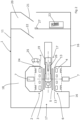
- the touchscreen control panel 24 is affixed to the imaging and treatment system 6 in a mounting arrangement behind fascia 8 shown in figures 4, 5 and 6 .
- the fascia 8 obscures the components of the combined MRI and radiotherapy imaging and treatment system 6 from view by a patient or staff member 25 with the exception of the touchscreen control panel 24, as shown in figures 1 to 3 .
- the fascia 8 is thus opaque with a transparent region forming transparent cover 36 against which the touchscreen control panel 24 may be mounted.
- the fascia 8 may, of course, be completely transparent if desired.
- the fascia is preferably polycarbonate for ease of forming the curved profile with planar regions, but may equally be formed of any suitable material, including glass.
- figures 1 to 3 indicate a single touchscreen control panel 24, a plurality of touchscreen control panels may be present to enable control of a plurality of functions, by one or more staff members, or simply for the convenience of staff members as they move around the operational spaces 17. Up to four touchscreen control panels may be visible to staff members positioned in one or both of the operation spaces 17. A plurality of transparent regions will be provided accordingly.
- a retaining structure 40 is provided between the transparent cover 36 and the touchscreen control panel 24 to affix the touchscreen control panel 24 against the rear face of the transparent cover 36.
- a staff member 25 may input commands to the touchscreen control panel 24 through the transparent cover 36 by touching the screen.
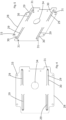
- the retaining structure 40 is comprised of a chassis 28 in the form of a plate that, in use, is mounted substantially parallel to the transparent cover 36 and the rear face 32 of the touchscreen control panel 24.
- the chassis 28 is removably mounted to the imaging and treatment system 6 using standard fixings 35 and is thus provided with fixing apertures 33.
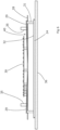
- a service aperture 34 is formed to accommodate power supply and other wired connections typically required for communication between a printed circuit board (PCB) 39 and the touchscreen control panel 24, as shown in figure 6 .
- the touchscreen control panel 24 can be a tablet or other touch screen controlled electronic device.
- a touchscreen control panel 24 is preferred, to allow networked control by the control unit of the main control terminal 23 via PCB 39.
- Slots 30 in the chassis 28 define elongate fingers 29 arranged in a symmetrical pattern.
- a protrusion 31 extends from the finger 29 toward the rear face of the touchscreen control panel 24.
- Each protrusion 31 attaches to the rear face of the touchscreen control panel 24, permanently or removably.
- the or each protrusion 31 is a rigid member with a depth greater than the spacing between the chassis 28 and the rear face 32 of the touchscreen control panel 24.
- the protrusion 31 acts as a spacer causing the end part of the associated finger 29 to move out of the plane of the chassis 28 such that the finger 29 is retained at an acute angle to the plane of the chassis 28.
- the chassis 28 is formed of a suitable material appropriately dimensioned to enable cooperation between finger 29 and its associated protrusion 31 to provide a resilient biasing force against the rear face of the touchscreen control panel 24 such that the touchscreen control panel 24 bears against the rear face of the transparent cover 36.
- the arrangement of finger 29 and its associated protrusion 31 provides shock absorbance in the event that impact or undue pressure is applied to the fascia 8.
- the touchscreen control panel 24 can move away from the fascia 8 this preventing damage to the touchscreen control panel 24.
- the fascia 8 may be replaced independently of the touchscreen control panel 24, and vice versa. It will of course be understood that many variations may be made to the above-described embodiment without departing from the scope of the present invention.
- the touchscreen control panel may be integrated into a tablet device or small computing device that is mounted to the retaining structure in a similar manner to that described in the above defined embodiment.
- the tablet device may be battery or mains powered.
- the tablet device may be networked to the main control terminal 23 so as to send and/or receive information from the main control terminal.
- the tablet device may receive signals from the control unit, or may not be networked
- a screen or display may be provided in place of a touch screen control panel. Said display may be present to convey information to the staff member and/or patient.
- the protrusion may be formed of a rigid material or a resilient material.
- the protrusion may be a spring dimensioned such that the length of the spring in compressed form is greater than the spacing between the chassis and rear face of the control panel when the chassis and control panel are mounted.
Landscapes
- Health & Medical Sciences (AREA)
- Life Sciences & Earth Sciences (AREA)
- Engineering & Computer Science (AREA)
- Physics & Mathematics (AREA)
- Biomedical Technology (AREA)
- General Health & Medical Sciences (AREA)
- Nuclear Medicine, Radiotherapy & Molecular Imaging (AREA)
- Pathology (AREA)
- Public Health (AREA)
- Veterinary Medicine (AREA)
- Animal Behavior & Ethology (AREA)
- Radiology & Medical Imaging (AREA)
- Medical Informatics (AREA)
- Heart & Thoracic Surgery (AREA)
- Surgery (AREA)
- Molecular Biology (AREA)
- Biophysics (AREA)
- High Energy & Nuclear Physics (AREA)
- General Physics & Mathematics (AREA)
- Condensed Matter Physics & Semiconductors (AREA)
- Signal Processing (AREA)
- General Engineering & Computer Science (AREA)
- Pulmonology (AREA)
- Theoretical Computer Science (AREA)
- Optics & Photonics (AREA)
- Mechanical Engineering (AREA)
- Human Computer Interaction (AREA)
- Multimedia (AREA)
- Radiation-Therapy Devices (AREA)
- Magnetic Resonance Imaging Apparatus (AREA)
Claims (15)
- Befestigungsanordnung für eine Anzeigevorrichtung, wobei die Befestigungsanordnung eine transparente Abdeckung (36), die konfiguriert ist, um eine Anzeigevorrichtung gegen eine Rückseite der transparenten Abdeckung aufzunehmen, so dass sie durch eine Vorderseite der transparenten Abdeckung sichtbar ist, und eine Haltestruktur (40) zum Halten der Anzeigevorrichtung an ihrem Platz aufweist,
wobei die Haltestruktur (40) ein Chassis (28) aufweist, das in einer Position relativ zu der Abdeckung (36) fixierbar ist, wobei das Chassis mindestens einen Schlitz aufweist, wobei der mindestens eine Schlitz mindestens einen elastischen Finger (29) definiert, wobei der mindestens eine elastische Finger angeordnet ist, um sich entlang einer Rückseite der Anzeigevorrichtung zu erstrecken, wobei ein Teil davon gegen die Rückseite der Anzeigevorrichtung anliegt, um die Anzeigevorrichtung elastisch gegen die Rückseite der transparenten Abdeckung (36) zu drücken. - Befestigungsanordnung nach einem der vorhergehenden Ansprüche, wobei der mindestens eine elastische Finger (29) einen Vorsprung (31) aufweist, der an der Rückseite der Anzeigevorrichtung anliegt.
- Befestigungsanordnung nach Anspruch 2, wobei der Vorsprung (31) eine Tiefe hat, die größer ist als der Abstand zwischen dem Chassis (28) und der Rückseite der Anzeigevorrichtung, wenn das Chassis (28) und die Anzeigevorrichtung befestigt sind.
- Befestigungsanordnung nach Anspruch 2 oder Anspruch 3, wobei sich der Vorsprung (31) an einem Endabschnitt des elastischen Fingers (29) befindet.
- Befestigungsanordnung nach einem der vorhergehenden Ansprüche, wobei das Chassis (28) mehrere elastische Finger (29) aufweist.
- Befestigungsanordnung nach Anspruch 5, wobei die elastischen Finger in einem symmetrischen Muster angeordnet sind.
- Befestigungsanordnung nach einem der vorhergehenden Ansprüche, wobei das Chassis (28) eine Platte ist.
- Befestigungsanordnung nach Anspruch 7, wobei die Platte relativ zu der Abdeckung (36) abnehmbar fixierbar ist.
- Befestigungsanordnung nach Anspruch 8, wobei der oder jeder elastische Finger (29) ein Teil der Platte ist, der durch einen in der Platte gebildeten bogenförmigen Schlitz (30) definiert ist.
- Befestigungsanordnung nach Anspruch 9, wobei der Schlitz (30) U-förmig ist.
- Befestigungsanordnung nach einem der vorhergehenden Ansprüche, wobei die Abdeckung (36) aus Polycarbonat hergestellt ist.
- Befestigungsanordnung nach einem der vorhergehenden Ansprüche, wobei die Anzeigevorrichtung in mindestens einer Richtung parallel zu der Ebene der Abdeckung (36) gehalten wird.
- Strahlentherapievorrichtung mit einer Anzeigevorrichtung, wobei die Anzeigevorrichtung unter Verwendung einer Befestigungsanordnung nach einem der vorhergehenden Ansprüche befestigt ist.
- Strahlentherapievorrichtung nach Anspruch 13, wobei die Anzeigevorrichtung eine Touchscreen-Vorrichtung ist.
- Strahlentherapievorrichtung nach Anspruch 13, wobei die Anzeigevorrichtung ein Bedienfeld ist.
Applications Claiming Priority (1)
| Application Number | Priority Date | Filing Date | Title |
|---|---|---|---|
| GB1718288.2A GB2568080B (en) | 2017-11-03 | 2017-11-03 | Operation and control of magnetic resonance imaging apparatus |
Publications (2)
| Publication Number | Publication Date |
|---|---|
| EP3479875A1 EP3479875A1 (de) | 2019-05-08 |
| EP3479875B1 true EP3479875B1 (de) | 2024-01-10 |
Family
ID=60664865
Family Applications (1)
| Application Number | Title | Priority Date | Filing Date |
|---|---|---|---|
| EP18199820.4A Active EP3479875B1 (de) | 2017-11-03 | 2018-10-11 | Betrieb und steuerung einer magnetresonanzbildgebungsvorrichtung |
Country Status (6)
| Country | Link |
|---|---|
| US (1) | US11559262B2 (de) |
| EP (1) | EP3479875B1 (de) |
| CN (1) | CN109745630A (de) |
| AU (1) | AU2018241157A1 (de) |
| CA (1) | CA3019974A1 (de) |
| GB (1) | GB2568080B (de) |
Families Citing this family (4)
| Publication number | Priority date | Publication date | Assignee | Title |
|---|---|---|---|---|
| CN105264397B (zh) * | 2013-06-06 | 2018-11-09 | 皇家飞利浦有限公司 | 磁共振成像系统的rf屏蔽检查室 |
| DE102021203171B4 (de) | 2021-03-30 | 2023-04-27 | Siemens Healthcare Gmbh | Medizinisches Bildgebungsgerät und Verfahren zum Betrieb eines medizinischen Bildgebungsgeräts |
| EP4375690A1 (de) * | 2022-11-24 | 2024-05-29 | Siemens Healthineers AG | Steuerung einer objekttransporteinheit eines untersuchungssystems mittels berührbildschirm |
| CN115919285A (zh) * | 2023-02-28 | 2023-04-07 | 山东奥新医疗科技有限公司 | 一种核磁共振定位方法、装置、设备及存储介质 |
Family Cites Families (24)
| Publication number | Priority date | Publication date | Assignee | Title |
|---|---|---|---|---|
| JPS5915937Y2 (ja) * | 1979-09-12 | 1984-05-11 | 陽介 二宮 | テ−ブル |
| JPS5915937A (ja) * | 1982-07-20 | 1984-01-27 | Copal Co Ltd | 写真処理システム装置の紙送り機構 |
| US4710947A (en) * | 1985-09-30 | 1987-12-01 | Siemens Aktiengesellschaft | Collimator for a radiation diagnostics apparatus |
| US6757416B2 (en) * | 2000-12-04 | 2004-06-29 | Ge Medical Systems Global Technology Company, Llc | Display of patient image data |
| US6821091B2 (en) * | 2002-06-05 | 2004-11-23 | Litex Industries Inc. | Securing device |
| JP2005091971A (ja) * | 2003-09-19 | 2005-04-07 | Hitachi Displays Ltd | 表示装置 |
| TWM247898U (en) * | 2003-12-02 | 2004-10-21 | Hon Hai Prec Ind Co Ltd | Mounting apparatus for power supply |
| US7413473B2 (en) * | 2005-08-26 | 2008-08-19 | Hon Hai Precision Ind. Co., Ltd. | Cable connector assembly with EMI gasket |
| JP4893302B2 (ja) * | 2006-12-28 | 2012-03-07 | 船井電機株式会社 | パネル型テレビジョンおよび表示パネル取付構造 |
| US9778685B2 (en) * | 2011-05-04 | 2017-10-03 | Apple Inc. | Housing for portable electronic device with reduced border region |
| EP2648806B1 (de) * | 2010-12-08 | 2015-02-18 | Elekta AB (publ) | Gerät für strahlentherapie |
| CA3055149A1 (en) * | 2010-12-22 | 2012-06-28 | Viewray Technologies, Inc. | System and method for image guidance during medical procedures |
| DE102011077892A1 (de) * | 2011-06-21 | 2012-12-27 | Siemens Ag | Bedienvorrichtung und Gerät |
| WO2013068858A1 (pt) * | 2011-11-11 | 2013-05-16 | Laborial, Soluções Para Laboratório S.A. | Superfície de trabalho com zona interactiva para ambiente de laboratório controlado |
| JP5806634B2 (ja) * | 2012-03-15 | 2015-11-10 | アルパイン株式会社 | タッチスクリーン装置 |
| JP6344241B2 (ja) * | 2012-12-07 | 2018-06-20 | パナソニックIpマネジメント株式会社 | 家具ユニット |
| US9038698B2 (en) * | 2012-12-18 | 2015-05-26 | Ply Gem Industries, Inc. | Quick release screen clips |
| US9675271B2 (en) * | 2013-03-13 | 2017-06-13 | Viewray Technologies, Inc. | Systems and methods for radiotherapy with magnetic resonance imaging |
| DE102014207295B4 (de) * | 2014-04-16 | 2025-04-24 | Siemens Healthineers Ag | Magnetresonanzeinrichtung mit einer Anzeigevorrichtung |
| KR102277899B1 (ko) * | 2014-08-11 | 2021-07-15 | 삼성전자주식회사 | Rf 코일부 및 이를 포함하는 자기공명영상 시스템 |
| KR102237827B1 (ko) * | 2014-09-01 | 2021-04-08 | 삼성전자주식회사 | 유전 구조체를 포함하는 rf 코일부 및 이를 포함하는 자기공명영상 시스템 |
| DE102015211140A1 (de) * | 2015-06-17 | 2016-12-22 | Siemens Healthcare Gmbh | Verfahren zu einem Bedienen einer medizinischen Bildgebungsvorrichtung eines medizinischen Bildgebungssystems während einer medizinischen Bildgebungsuntersuchung sowie ein medizinisches Bildgebungssystem mit einer medizinischen Bildgebungsvorrichtung und einer Systemsteuerungseinheit |
| WO2018057645A1 (en) * | 2016-09-22 | 2018-03-29 | Apple Inc. | Battery architecture in an electronic device |
| DE102017205145A1 (de) * | 2017-03-27 | 2018-09-27 | Siemens Healthcare Gmbh | Gehäusevorrichtung mit einer Benutzerschnittstelle sowie eine medizinische Bildgebungsvorrichtung mit der Gehäusevorrichtung |
-
2017
- 2017-11-03 GB GB1718288.2A patent/GB2568080B/en active Active
-
2018
- 2018-10-04 CA CA3019974A patent/CA3019974A1/en active Pending
- 2018-10-05 AU AU2018241157A patent/AU2018241157A1/en not_active Abandoned
- 2018-10-11 EP EP18199820.4A patent/EP3479875B1/de active Active
- 2018-11-02 CN CN201811300871.XA patent/CN109745630A/zh active Pending
- 2018-11-02 US US16/179,175 patent/US11559262B2/en active Active
Also Published As
| Publication number | Publication date |
|---|---|
| GB2568080A (en) | 2019-05-08 |
| CN109745630A (zh) | 2019-05-14 |
| EP3479875A1 (de) | 2019-05-08 |
| AU2018241157A1 (en) | 2019-05-23 |
| US11559262B2 (en) | 2023-01-24 |
| US20190133538A1 (en) | 2019-05-09 |
| GB2568080B (en) | 2020-09-09 |
| GB201718288D0 (en) | 2017-12-20 |
| CA3019974A1 (en) | 2019-05-03 |
Similar Documents
| Publication | Publication Date | Title |
|---|---|---|
| EP3479875B1 (de) | Betrieb und steuerung einer magnetresonanzbildgebungsvorrichtung | |
| JP7421234B2 (ja) | 放出誘導型高エネルギー光子送達のためのシステム | |
| US6677752B1 (en) | Close-in shielding system for magnetic medical treatment instruments | |
| JP4268794B2 (ja) | 電子照射野撮像による線質の測定及び線量の測定を行うためのシステム及び方法 | |
| US6634790B1 (en) | Tomotherapy treatment table positioning device | |
| EP3572823A1 (de) | System zur bildgebung geteilter magnetischer resonanzen | |
| US20120253172A1 (en) | Radiation therapy system with high frequency shielding | |
| JP2002204798A (ja) | 放射線治療用の診断撮像装置 | |
| Chung et al. | The first private-hospital based proton therapy center in Korea; status of the Proton Therapy Center at Samsung Medical Center | |
| WO2009058733A1 (en) | A highly shielded radiation therapy system | |
| US11969285B2 (en) | Dose adjustment device mountable to diagnostic radiation equipment and dose adjustment system including same | |
| US9700475B2 (en) | Controlling access to radiotherapy systems | |
| CN104721961A (zh) | 全身式肿瘤放射治疗仪 | |
| Stanescu et al. | Commissioning of an MR-guided radiation therapy system | |
| CN207614190U (zh) | 一种放射治疗用的辅助装置 | |
| Fujii et al. | A simulation study of MR-guided proton therapy system using iron-yoked superconducting open MRI: a conceptual study | |
| Green et al. | Validation of the first clinical on-board magnetic resonance image guided radiation therapy (MR-IGRT) system | |
| CN222708859U (zh) | 新型框架结构及放射治疗系统 | |
| US20200305820A1 (en) | Diagnostic and therapeutic unit | |
| Evans et al. | Total body irradiation with a reconditioned cobalt teletherapy unit | |
| Ma et al. | Designing, Building, and Installing a Stereotactic Radiosurgery Unit | |
| Kuchnir | Medical Physics before the Millennium: a personal experience |
Legal Events
| Date | Code | Title | Description |
|---|---|---|---|
| PUAI | Public reference made under article 153(3) epc to a published international application that has entered the european phase |
Free format text: ORIGINAL CODE: 0009012 |
|
| STAA | Information on the status of an ep patent application or granted ep patent |
Free format text: STATUS: THE APPLICATION HAS BEEN PUBLISHED |
|
| AK | Designated contracting states |
Kind code of ref document: A1 Designated state(s): AL AT BE BG CH CY CZ DE DK EE ES FI FR GB GR HR HU IE IS IT LI LT LU LV MC MK MT NL NO PL PT RO RS SE SI SK SM TR |
|
| AX | Request for extension of the european patent |
Extension state: BA ME |
|
| STAA | Information on the status of an ep patent application or granted ep patent |
Free format text: STATUS: REQUEST FOR EXAMINATION WAS MADE |
|
| 17P | Request for examination filed |
Effective date: 20191031 |
|
| RBV | Designated contracting states (corrected) |
Designated state(s): AL AT BE BG CH CY CZ DE DK EE ES FI FR GB GR HR HU IE IS IT LI LT LU LV MC MK MT NL NO PL PT RO RS SE SI SK SM TR |
|
| STAA | Information on the status of an ep patent application or granted ep patent |
Free format text: STATUS: EXAMINATION IS IN PROGRESS |
|
| 17Q | First examination report despatched |
Effective date: 20200902 |
|
| GRAP | Despatch of communication of intention to grant a patent |
Free format text: ORIGINAL CODE: EPIDOSNIGR1 |
|
| STAA | Information on the status of an ep patent application or granted ep patent |
Free format text: STATUS: GRANT OF PATENT IS INTENDED |
|
| RIC1 | Information provided on ipc code assigned before grant |
Ipc: A61B 5/055 20060101ALN20230710BHEP Ipc: A61B 5/00 20060101ALI20230710BHEP Ipc: A61N 5/10 20060101AFI20230710BHEP |
|
| INTG | Intention to grant announced |
Effective date: 20230810 |
|
| RIC1 | Information provided on ipc code assigned before grant |
Ipc: A61B 5/055 20060101ALN20230728BHEP Ipc: A61B 5/00 20060101ALI20230728BHEP Ipc: A61N 5/10 20060101AFI20230728BHEP |
|
| GRAS | Grant fee paid |
Free format text: ORIGINAL CODE: EPIDOSNIGR3 |
|
| GRAA | (expected) grant |
Free format text: ORIGINAL CODE: 0009210 |
|
| STAA | Information on the status of an ep patent application or granted ep patent |
Free format text: STATUS: THE PATENT HAS BEEN GRANTED |
|
| AK | Designated contracting states |
Kind code of ref document: B1 Designated state(s): AL AT BE BG CH CY CZ DE DK EE ES FI FR GB GR HR HU IE IS IT LI LT LU LV MC MK MT NL NO PL PT RO RS SE SI SK SM TR |
|
| REG | Reference to a national code |
Ref country code: GB Ref legal event code: FG4D |
|
| REG | Reference to a national code |
Ref country code: CH Ref legal event code: EP |
|
| REG | Reference to a national code |
Ref country code: DE Ref legal event code: R096 Ref document number: 602018063902 Country of ref document: DE |
|
| REG | Reference to a national code |
Ref country code: IE Ref legal event code: FG4D |
|
| REG | Reference to a national code |
Ref country code: LT Ref legal event code: MG9D |
|
| REG | Reference to a national code |
Ref country code: NL Ref legal event code: MP Effective date: 20240110 |
|
| P01 | Opt-out of the competence of the unified patent court (upc) registered |
Effective date: 20240430 |
|
| REG | Reference to a national code |
Ref country code: AT Ref legal event code: MK05 Ref document number: 1648440 Country of ref document: AT Kind code of ref document: T Effective date: 20240110 |
|
| PG25 | Lapsed in a contracting state [announced via postgrant information from national office to epo] |
Ref country code: NL Free format text: LAPSE BECAUSE OF FAILURE TO SUBMIT A TRANSLATION OF THE DESCRIPTION OR TO PAY THE FEE WITHIN THE PRESCRIBED TIME-LIMIT Effective date: 20240110 |
|
| PG25 | Lapsed in a contracting state [announced via postgrant information from national office to epo] |
Ref country code: NL Free format text: LAPSE BECAUSE OF FAILURE TO SUBMIT A TRANSLATION OF THE DESCRIPTION OR TO PAY THE FEE WITHIN THE PRESCRIBED TIME-LIMIT Effective date: 20240110 |
|
| PG25 | Lapsed in a contracting state [announced via postgrant information from national office to epo] |
Ref country code: IS Free format text: LAPSE BECAUSE OF FAILURE TO SUBMIT A TRANSLATION OF THE DESCRIPTION OR TO PAY THE FEE WITHIN THE PRESCRIBED TIME-LIMIT Effective date: 20240510 |
|
| PG25 | Lapsed in a contracting state [announced via postgrant information from national office to epo] |
Ref country code: LT Free format text: LAPSE BECAUSE OF FAILURE TO SUBMIT A TRANSLATION OF THE DESCRIPTION OR TO PAY THE FEE WITHIN THE PRESCRIBED TIME-LIMIT Effective date: 20240110 |
|
| PG25 | Lapsed in a contracting state [announced via postgrant information from national office to epo] |
Ref country code: GR Free format text: LAPSE BECAUSE OF FAILURE TO SUBMIT A TRANSLATION OF THE DESCRIPTION OR TO PAY THE FEE WITHIN THE PRESCRIBED TIME-LIMIT Effective date: 20240411 |
|
| PG25 | Lapsed in a contracting state [announced via postgrant information from national office to epo] |
Ref country code: RS Free format text: LAPSE BECAUSE OF FAILURE TO SUBMIT A TRANSLATION OF THE DESCRIPTION OR TO PAY THE FEE WITHIN THE PRESCRIBED TIME-LIMIT Effective date: 20240410 Ref country code: HR Free format text: LAPSE BECAUSE OF FAILURE TO SUBMIT A TRANSLATION OF THE DESCRIPTION OR TO PAY THE FEE WITHIN THE PRESCRIBED TIME-LIMIT Effective date: 20240110 |
|
| PG25 | Lapsed in a contracting state [announced via postgrant information from national office to epo] |
Ref country code: ES Free format text: LAPSE BECAUSE OF FAILURE TO SUBMIT A TRANSLATION OF THE DESCRIPTION OR TO PAY THE FEE WITHIN THE PRESCRIBED TIME-LIMIT Effective date: 20240110 |
|
| PG25 | Lapsed in a contracting state [announced via postgrant information from national office to epo] |
Ref country code: AT Free format text: LAPSE BECAUSE OF FAILURE TO SUBMIT A TRANSLATION OF THE DESCRIPTION OR TO PAY THE FEE WITHIN THE PRESCRIBED TIME-LIMIT Effective date: 20240110 |
|
| PG25 | Lapsed in a contracting state [announced via postgrant information from national office to epo] |
Ref country code: RS Free format text: LAPSE BECAUSE OF FAILURE TO SUBMIT A TRANSLATION OF THE DESCRIPTION OR TO PAY THE FEE WITHIN THE PRESCRIBED TIME-LIMIT Effective date: 20240410 Ref country code: NO Free format text: LAPSE BECAUSE OF FAILURE TO SUBMIT A TRANSLATION OF THE DESCRIPTION OR TO PAY THE FEE WITHIN THE PRESCRIBED TIME-LIMIT Effective date: 20240410 Ref country code: LT Free format text: LAPSE BECAUSE OF FAILURE TO SUBMIT A TRANSLATION OF THE DESCRIPTION OR TO PAY THE FEE WITHIN THE PRESCRIBED TIME-LIMIT Effective date: 20240110 Ref country code: IS Free format text: LAPSE BECAUSE OF FAILURE TO SUBMIT A TRANSLATION OF THE DESCRIPTION OR TO PAY THE FEE WITHIN THE PRESCRIBED TIME-LIMIT Effective date: 20240510 Ref country code: HR Free format text: LAPSE BECAUSE OF FAILURE TO SUBMIT A TRANSLATION OF THE DESCRIPTION OR TO PAY THE FEE WITHIN THE PRESCRIBED TIME-LIMIT Effective date: 20240110 Ref country code: GR Free format text: LAPSE BECAUSE OF FAILURE TO SUBMIT A TRANSLATION OF THE DESCRIPTION OR TO PAY THE FEE WITHIN THE PRESCRIBED TIME-LIMIT Effective date: 20240411 Ref country code: ES Free format text: LAPSE BECAUSE OF FAILURE TO SUBMIT A TRANSLATION OF THE DESCRIPTION OR TO PAY THE FEE WITHIN THE PRESCRIBED TIME-LIMIT Effective date: 20240110 Ref country code: BG Free format text: LAPSE BECAUSE OF FAILURE TO SUBMIT A TRANSLATION OF THE DESCRIPTION OR TO PAY THE FEE WITHIN THE PRESCRIBED TIME-LIMIT Effective date: 20240110 Ref country code: AT Free format text: LAPSE BECAUSE OF FAILURE TO SUBMIT A TRANSLATION OF THE DESCRIPTION OR TO PAY THE FEE WITHIN THE PRESCRIBED TIME-LIMIT Effective date: 20240110 |
|
| PG25 | Lapsed in a contracting state [announced via postgrant information from national office to epo] |
Ref country code: PT Free format text: LAPSE BECAUSE OF FAILURE TO SUBMIT A TRANSLATION OF THE DESCRIPTION OR TO PAY THE FEE WITHIN THE PRESCRIBED TIME-LIMIT Effective date: 20240510 Ref country code: PL Free format text: LAPSE BECAUSE OF FAILURE TO SUBMIT A TRANSLATION OF THE DESCRIPTION OR TO PAY THE FEE WITHIN THE PRESCRIBED TIME-LIMIT Effective date: 20240110 |
|
| PG25 | Lapsed in a contracting state [announced via postgrant information from national office to epo] |
Ref country code: SE Free format text: LAPSE BECAUSE OF FAILURE TO SUBMIT A TRANSLATION OF THE DESCRIPTION OR TO PAY THE FEE WITHIN THE PRESCRIBED TIME-LIMIT Effective date: 20240110 Ref country code: PT Free format text: LAPSE BECAUSE OF FAILURE TO SUBMIT A TRANSLATION OF THE DESCRIPTION OR TO PAY THE FEE WITHIN THE PRESCRIBED TIME-LIMIT Effective date: 20240510 Ref country code: PL Free format text: LAPSE BECAUSE OF FAILURE TO SUBMIT A TRANSLATION OF THE DESCRIPTION OR TO PAY THE FEE WITHIN THE PRESCRIBED TIME-LIMIT Effective date: 20240110 Ref country code: LV Free format text: LAPSE BECAUSE OF FAILURE TO SUBMIT A TRANSLATION OF THE DESCRIPTION OR TO PAY THE FEE WITHIN THE PRESCRIBED TIME-LIMIT Effective date: 20240110 |
|
| PG25 | Lapsed in a contracting state [announced via postgrant information from national office to epo] |
Ref country code: DK Free format text: LAPSE BECAUSE OF FAILURE TO SUBMIT A TRANSLATION OF THE DESCRIPTION OR TO PAY THE FEE WITHIN THE PRESCRIBED TIME-LIMIT Effective date: 20240110 |
|
| REG | Reference to a national code |
Ref country code: DE Ref legal event code: R097 Ref document number: 602018063902 Country of ref document: DE |
|
| PG25 | Lapsed in a contracting state [announced via postgrant information from national office to epo] |
Ref country code: SM Free format text: LAPSE BECAUSE OF FAILURE TO SUBMIT A TRANSLATION OF THE DESCRIPTION OR TO PAY THE FEE WITHIN THE PRESCRIBED TIME-LIMIT Effective date: 20240110 |
|
| PG25 | Lapsed in a contracting state [announced via postgrant information from national office to epo] |
Ref country code: EE Free format text: LAPSE BECAUSE OF FAILURE TO SUBMIT A TRANSLATION OF THE DESCRIPTION OR TO PAY THE FEE WITHIN THE PRESCRIBED TIME-LIMIT Effective date: 20240110 Ref country code: CZ Free format text: LAPSE BECAUSE OF FAILURE TO SUBMIT A TRANSLATION OF THE DESCRIPTION OR TO PAY THE FEE WITHIN THE PRESCRIBED TIME-LIMIT Effective date: 20240110 |
|
| PG25 | Lapsed in a contracting state [announced via postgrant information from national office to epo] |
Ref country code: SK Free format text: LAPSE BECAUSE OF FAILURE TO SUBMIT A TRANSLATION OF THE DESCRIPTION OR TO PAY THE FEE WITHIN THE PRESCRIBED TIME-LIMIT Effective date: 20240110 |
|
| PG25 | Lapsed in a contracting state [announced via postgrant information from national office to epo] |
Ref country code: SM Free format text: LAPSE BECAUSE OF FAILURE TO SUBMIT A TRANSLATION OF THE DESCRIPTION OR TO PAY THE FEE WITHIN THE PRESCRIBED TIME-LIMIT Effective date: 20240110 Ref country code: SK Free format text: LAPSE BECAUSE OF FAILURE TO SUBMIT A TRANSLATION OF THE DESCRIPTION OR TO PAY THE FEE WITHIN THE PRESCRIBED TIME-LIMIT Effective date: 20240110 Ref country code: RO Free format text: LAPSE BECAUSE OF FAILURE TO SUBMIT A TRANSLATION OF THE DESCRIPTION OR TO PAY THE FEE WITHIN THE PRESCRIBED TIME-LIMIT Effective date: 20240110 Ref country code: EE Free format text: LAPSE BECAUSE OF FAILURE TO SUBMIT A TRANSLATION OF THE DESCRIPTION OR TO PAY THE FEE WITHIN THE PRESCRIBED TIME-LIMIT Effective date: 20240110 Ref country code: DK Free format text: LAPSE BECAUSE OF FAILURE TO SUBMIT A TRANSLATION OF THE DESCRIPTION OR TO PAY THE FEE WITHIN THE PRESCRIBED TIME-LIMIT Effective date: 20240110 Ref country code: CZ Free format text: LAPSE BECAUSE OF FAILURE TO SUBMIT A TRANSLATION OF THE DESCRIPTION OR TO PAY THE FEE WITHIN THE PRESCRIBED TIME-LIMIT Effective date: 20240110 |
|
| PLBE | No opposition filed within time limit |
Free format text: ORIGINAL CODE: 0009261 |
|
| STAA | Information on the status of an ep patent application or granted ep patent |
Free format text: STATUS: NO OPPOSITION FILED WITHIN TIME LIMIT |
|
| PG25 | Lapsed in a contracting state [announced via postgrant information from national office to epo] |
Ref country code: IT Free format text: LAPSE BECAUSE OF FAILURE TO SUBMIT A TRANSLATION OF THE DESCRIPTION OR TO PAY THE FEE WITHIN THE PRESCRIBED TIME-LIMIT Effective date: 20240110 |
|
| 26N | No opposition filed |
Effective date: 20241011 |
|
| PG25 | Lapsed in a contracting state [announced via postgrant information from national office to epo] |
Ref country code: IT Free format text: LAPSE BECAUSE OF FAILURE TO SUBMIT A TRANSLATION OF THE DESCRIPTION OR TO PAY THE FEE WITHIN THE PRESCRIBED TIME-LIMIT Effective date: 20240110 |
|
| PG25 | Lapsed in a contracting state [announced via postgrant information from national office to epo] |
Ref country code: SI Free format text: LAPSE BECAUSE OF FAILURE TO SUBMIT A TRANSLATION OF THE DESCRIPTION OR TO PAY THE FEE WITHIN THE PRESCRIBED TIME-LIMIT Effective date: 20240110 |
|
| REG | Reference to a national code |
Ref country code: CH Ref legal event code: PL |
|
| PG25 | Lapsed in a contracting state [announced via postgrant information from national office to epo] |
Ref country code: MC Free format text: LAPSE BECAUSE OF FAILURE TO SUBMIT A TRANSLATION OF THE DESCRIPTION OR TO PAY THE FEE WITHIN THE PRESCRIBED TIME-LIMIT Effective date: 20240110 |
|
| PG25 | Lapsed in a contracting state [announced via postgrant information from national office to epo] |
Ref country code: BE Free format text: LAPSE BECAUSE OF NON-PAYMENT OF DUE FEES Effective date: 20241031 Ref country code: LU Free format text: LAPSE BECAUSE OF NON-PAYMENT OF DUE FEES Effective date: 20241011 |
|
| PG25 | Lapsed in a contracting state [announced via postgrant information from national office to epo] |
Ref country code: CH Free format text: LAPSE BECAUSE OF NON-PAYMENT OF DUE FEES Effective date: 20241031 |
|
| REG | Reference to a national code |
Ref country code: BE Ref legal event code: MM Effective date: 20241031 |
|
| PG25 | Lapsed in a contracting state [announced via postgrant information from national office to epo] |
Ref country code: FI Free format text: LAPSE BECAUSE OF FAILURE TO SUBMIT A TRANSLATION OF THE DESCRIPTION OR TO PAY THE FEE WITHIN THE PRESCRIBED TIME-LIMIT Effective date: 20240110 |
|
| PGFP | Annual fee paid to national office [announced via postgrant information from national office to epo] |
Ref country code: GB Payment date: 20250904 Year of fee payment: 8 |
|
| PGFP | Annual fee paid to national office [announced via postgrant information from national office to epo] |
Ref country code: FR Payment date: 20250908 Year of fee payment: 8 |
|
| PG25 | Lapsed in a contracting state [announced via postgrant information from national office to epo] |
Ref country code: IE Free format text: LAPSE BECAUSE OF NON-PAYMENT OF DUE FEES Effective date: 20241011 |
|
| PGFP | Annual fee paid to national office [announced via postgrant information from national office to epo] |
Ref country code: DE Payment date: 20250902 Year of fee payment: 8 |
|
| PG25 | Lapsed in a contracting state [announced via postgrant information from national office to epo] |
Ref country code: CY Free format text: LAPSE BECAUSE OF FAILURE TO SUBMIT A TRANSLATION OF THE DESCRIPTION OR TO PAY THE FEE WITHIN THE PRESCRIBED TIME-LIMIT; INVALID AB INITIO Effective date: 20181011 |