EP3477189B1 - Module lumineux - Google Patents
Module lumineux Download PDFInfo
- Publication number
- EP3477189B1 EP3477189B1 EP18202016.4A EP18202016A EP3477189B1 EP 3477189 B1 EP3477189 B1 EP 3477189B1 EP 18202016 A EP18202016 A EP 18202016A EP 3477189 B1 EP3477189 B1 EP 3477189B1
- Authority
- EP
- European Patent Office
- Prior art keywords
- lens
- recess
- wall
- light
- lenses
- Prior art date
- Legal status (The legal status is an assumption and is not a legal conclusion. Google has not performed a legal analysis and makes no representation as to the accuracy of the status listed.)
- Active
Links
- 238000004519 manufacturing process Methods 0.000 claims description 11
- 230000007423 decrease Effects 0.000 claims description 4
- 238000009826 distribution Methods 0.000 description 12
- 230000003287 optical effect Effects 0.000 description 7
- 239000004033 plastic Substances 0.000 description 6
- 229920003023 plastic Polymers 0.000 description 6
- 239000000463 material Substances 0.000 description 5
- 239000011521 glass Substances 0.000 description 4
- 239000011159 matrix material Substances 0.000 description 4
- 230000001427 coherent effect Effects 0.000 description 3
- 238000010276 construction Methods 0.000 description 2
- 238000005520 cutting process Methods 0.000 description 2
- 238000007788 roughening Methods 0.000 description 2
- 238000000149 argon plasma sintering Methods 0.000 description 1
- 230000001174 ascending effect Effects 0.000 description 1
- 230000001419 dependent effect Effects 0.000 description 1
- 238000011161 development Methods 0.000 description 1
- 230000018109 developmental process Effects 0.000 description 1
- 230000000694 effects Effects 0.000 description 1
- 239000002245 particle Substances 0.000 description 1
- 229920003229 poly(methyl methacrylate) Polymers 0.000 description 1
- 239000004926 polymethyl methacrylate Substances 0.000 description 1
- 230000005855 radiation Effects 0.000 description 1
- 238000007493 shaping process Methods 0.000 description 1
Images


Classifications
-
- G—PHYSICS
- G02—OPTICS
- G02B—OPTICAL ELEMENTS, SYSTEMS OR APPARATUS
- G02B19/00—Condensers, e.g. light collectors or similar non-imaging optics
- G02B19/0004—Condensers, e.g. light collectors or similar non-imaging optics characterised by the optical means employed
- G02B19/0028—Condensers, e.g. light collectors or similar non-imaging optics characterised by the optical means employed refractive and reflective surfaces, e.g. non-imaging catadioptric systems
-
- F—MECHANICAL ENGINEERING; LIGHTING; HEATING; WEAPONS; BLASTING
- F21—LIGHTING
- F21S—NON-PORTABLE LIGHTING DEVICES; SYSTEMS THEREOF; VEHICLE LIGHTING DEVICES SPECIALLY ADAPTED FOR VEHICLE EXTERIORS
- F21S4/00—Lighting devices or systems using a string or strip of light sources
- F21S4/20—Lighting devices or systems using a string or strip of light sources with light sources held by or within elongate supports
- F21S4/28—Lighting devices or systems using a string or strip of light sources with light sources held by or within elongate supports rigid, e.g. LED bars
-
- F—MECHANICAL ENGINEERING; LIGHTING; HEATING; WEAPONS; BLASTING
- F21—LIGHTING
- F21V—FUNCTIONAL FEATURES OR DETAILS OF LIGHTING DEVICES OR SYSTEMS THEREOF; STRUCTURAL COMBINATIONS OF LIGHTING DEVICES WITH OTHER ARTICLES, NOT OTHERWISE PROVIDED FOR
- F21V5/00—Refractors for light sources
- F21V5/007—Array of lenses or refractors for a cluster of light sources, e.g. for arrangement of multiple light sources in one plane
-
- F—MECHANICAL ENGINEERING; LIGHTING; HEATING; WEAPONS; BLASTING
- F21—LIGHTING
- F21V—FUNCTIONAL FEATURES OR DETAILS OF LIGHTING DEVICES OR SYSTEMS THEREOF; STRUCTURAL COMBINATIONS OF LIGHTING DEVICES WITH OTHER ARTICLES, NOT OTHERWISE PROVIDED FOR
- F21V5/00—Refractors for light sources
- F21V5/02—Refractors for light sources of prismatic shape
-
- F—MECHANICAL ENGINEERING; LIGHTING; HEATING; WEAPONS; BLASTING
- F21—LIGHTING
- F21V—FUNCTIONAL FEATURES OR DETAILS OF LIGHTING DEVICES OR SYSTEMS THEREOF; STRUCTURAL COMBINATIONS OF LIGHTING DEVICES WITH OTHER ARTICLES, NOT OTHERWISE PROVIDED FOR
- F21V7/00—Reflectors for light sources
- F21V7/0091—Reflectors for light sources using total internal reflection
-
- G—PHYSICS
- G02—OPTICS
- G02B—OPTICAL ELEMENTS, SYSTEMS OR APPARATUS
- G02B19/00—Condensers, e.g. light collectors or similar non-imaging optics
- G02B19/0033—Condensers, e.g. light collectors or similar non-imaging optics characterised by the use
- G02B19/0047—Condensers, e.g. light collectors or similar non-imaging optics characterised by the use for use with a light source
- G02B19/0061—Condensers, e.g. light collectors or similar non-imaging optics characterised by the use for use with a light source the light source comprising a LED
- G02B19/0066—Condensers, e.g. light collectors or similar non-imaging optics characterised by the use for use with a light source the light source comprising a LED in the form of an LED array
-
- F—MECHANICAL ENGINEERING; LIGHTING; HEATING; WEAPONS; BLASTING
- F21—LIGHTING
- F21V—FUNCTIONAL FEATURES OR DETAILS OF LIGHTING DEVICES OR SYSTEMS THEREOF; STRUCTURAL COMBINATIONS OF LIGHTING DEVICES WITH OTHER ARTICLES, NOT OTHERWISE PROVIDED FOR
- F21V17/00—Fastening of component parts of lighting devices, e.g. shades, globes, refractors, reflectors, filters, screens, grids or protective cages
- F21V17/10—Fastening of component parts of lighting devices, e.g. shades, globes, refractors, reflectors, filters, screens, grids or protective cages characterised by specific fastening means or way of fastening
- F21V17/16—Fastening of component parts of lighting devices, e.g. shades, globes, refractors, reflectors, filters, screens, grids or protective cages characterised by specific fastening means or way of fastening by deformation of parts; Snap action mounting
- F21V17/164—Fastening of component parts of lighting devices, e.g. shades, globes, refractors, reflectors, filters, screens, grids or protective cages characterised by specific fastening means or way of fastening by deformation of parts; Snap action mounting the parts being subjected to bending, e.g. snap joints
-
- F—MECHANICAL ENGINEERING; LIGHTING; HEATING; WEAPONS; BLASTING
- F21—LIGHTING
- F21V—FUNCTIONAL FEATURES OR DETAILS OF LIGHTING DEVICES OR SYSTEMS THEREOF; STRUCTURAL COMBINATIONS OF LIGHTING DEVICES WITH OTHER ARTICLES, NOT OTHERWISE PROVIDED FOR
- F21V5/00—Refractors for light sources
- F21V5/04—Refractors for light sources of lens shape
-
- F—MECHANICAL ENGINEERING; LIGHTING; HEATING; WEAPONS; BLASTING
- F21—LIGHTING
- F21Y—INDEXING SCHEME ASSOCIATED WITH SUBCLASSES F21K, F21L, F21S and F21V, RELATING TO THE FORM OR THE KIND OF THE LIGHT SOURCES OR OF THE COLOUR OF THE LIGHT EMITTED
- F21Y2115/00—Light-generating elements of semiconductor light sources
- F21Y2115/10—Light-emitting diodes [LED]
-
- G—PHYSICS
- G02—OPTICS
- G02B—OPTICAL ELEMENTS, SYSTEMS OR APPARATUS
- G02B3/00—Simple or compound lenses
- G02B3/02—Simple or compound lenses with non-spherical faces
- G02B3/08—Simple or compound lenses with non-spherical faces with discontinuous faces, e.g. Fresnel lens
Definitions
- the invention relates to a lighting module.
- the document US 2015/192257 A1 reveals a lens and a light module.
- the document WO 2009/016586 A1 discloses a TIR collimator.
- the document US 9,360,190 B1 reveals a lens.
- the document US 2009/128921 A1 discloses a TIR collimator.
- One problem to be solved is to provide a lighting module with a lens that is flat in construction.
- the lens comprises an entrance surface through which light enters the lens when the lens is operating as intended, and an exit surface, through which light is coupled out of the lens when the lens is operating as intended.
- the entry surface is arranged downstream of the exit surface in a first direction. The first direction is therefore a direction away from the exit surface and towards the entrance surface.
- the lens comprises an elevation that tapers in the first direction.
- the elevation includes a laterally circumferential outer wall.
- the outer wall limits the elevation in a lateral direction.
- the first direction is a direction along which the elevation tapers.
- the lateral direction is a direction perpendicular to the first direction.
- the first direction is in particular a direction parallel to an optical axis of the lens.
- the elevation is in particular dome-shaped or dome-shaped elevations.
- the elevation can essentially have the geometric shape of a truncated cone or a truncated pyramid.
- the outer wall of the elevations has the geometric shape of a lateral surface of a truncated cone or a truncated pyramid.
- a first recess is formed in the elevation in the area of the elevation facing away from the exit surface. During normal operation, light is coupled into the lens in the area of the first recess.
- the recess is formed in the area of the tip of the elevation or in the area of the elevation where the lateral extent of the elevations is smallest.
- the outer wall completely laterally surrounds the first recess.
- the first recess of the elevation is laterally completely surrounded by a continuous path of the outer wall. Any along a lateral direction A straight line, starting from a point within the first recess, crosses the outer wall of the elevation.
- a height of the outer wall measured along the first direction in the lighting module is at least 50% or at least 60% or at least 70% or at least 75% of the height of the entire lens everywhere around the recess.
- the height of the lens is also measured along the first direction. The height of the outer wall or the lens is therefore the extent of the outer wall or the lens along the first direction.
- a light source can be arranged in the lighting module with respect to the lens in such a way that, during operation of the light source, light from the light source is coupled into the lens in the area of the first recess, then hits the outer wall and largely, for example at least 50% or so, on the outer wall at least 75% or at least 90% is totally reflected in the direction of the exit surface.
- the light source for example, has a Lambertian radiation profile and emits this onto the lens.
- a light source above the first recess or in the first recess, for example at a distance from a light exit surface of the light source to the lens of at most 10 cm or at most 5 cm or at most 1 cm, and the light source emits light into the recess, so light enters the lens in the area of the recess. This light can then hit the exit surface directly and be coupled out. However, part of the light coupled in in the area of the recess can first hit the outer wall of the elevation that laterally surrounds the recess.
- the outer wall is designed so that in the area of the recess in the The light entering the lens is totally reflected on the outer wall and then directed towards the underside.
- the totally reflective property of the outer wall results in particular from the tapering geometry of the elevation.
- the exit surface of a lens is defined here in particular by the area of a lens through which the light is coupled out during operation.
- each of the lenses in the lighting module comprises an entrance surface through which light enters the lens when the lens is operating as intended, and an exit surface through which light is coupled out of the lens when the lens is operating as intended.
- the entry surface is arranged downstream of the exit surface in a first direction.
- the lens includes an elevation that tapers in the first direction and has a laterally circumferential outer wall. In the area of the elevation facing away from the exit surface, a first recess is formed in the elevation. The outer wall completely surrounds the recess laterally. A height of the outer wall measured along the first direction is at least 50% of the height of the entire lens everywhere around the recess.
- a light source can be arranged with respect to the lens in such a way that, during operation of the light source, light from the light source is coupled into the lens in the area of the first recess, then hits the outer wall and is largely totally reflected on the outer wall in the direction of the exit surface.
- the present invention is based in particular on the knowledge that a lens as described here is particularly compact in construction.
- the combination of a recess through which light can enter the lens with the tapered shape of the lens ensures that the Recesses into the lenses allow light to be totally reflected on the large outer wall, meaning that the lenses bundle light particularly efficiently.
- the first recess extends from a first opening in the lens to a first bottom surface.
- the first opening is formed in the upper area of the survey.
- the first bottom surface is shifted relative to the opening towards the exit surface.
- a distance between the first opening and the first bottom surface or the depth of the first recess measured against the first direction is, for example, at least 1 mm or at least 2 mm or at least 3 mm. Alternatively or additionally, the distance or depth is a maximum of 5 mm or a maximum of 4 mm. For example, the depth of the first recess is at least 10% or at least 20% of the height of the lens. Alternatively or additionally, the depth of the first recess is at most 50% or at most 40% of the height of the lens.
- the first bottom surface has, for example, a mean lateral extent, measured perpendicular to the first direction, of at least 2 mm or at least 3 mm. Alternatively or additionally, the mean lateral extent is at most 5 mm or at most 4 mm. For example, the average lateral extent of the first floor area is at least 30% or at least 40% of the maximum lateral extent of the survey. Alternatively or additionally, the mean lateral extent of the first floor area is at most 60% or at most 50% of the maximum lateral extent of the elevation.
- the first recess is delimited in the lateral direction by a first inner wall of the lens.
- the first inner wall preferably completely surrounds the first recess in the lateral direction.
- the recess is completely surrounded by a coherent path of the inner wall.
- the first outer wall in turn completely surrounds the first inner wall in the lateral direction.
- the outer wall and the first inner wall preferably intersect along an edge. This edge forms, for example, the contour of the first opening.
- the first floor surface and the inner wall preferably also intersect along a contour that laterally delimits and completely surrounds the floor surface.
- the entrance surface of the lens comprises the first bottom surface and the first inner wall.
- the entrance surface of the lens comprises the first bottom surface and the first inner wall.
- light enters the lens via the first floor surface and the first inner wall.
- the outer wall, the first bottom surface and the first inner wall in particular form outer surfaces of the lens.
- these surfaces border a gaseous medium, such as air.
- the outer wall overlaps in a direction opposite to the first direction with the first opening, the first inner wall and the first floor surface and projects beyond the first floor surface.
- the outer wall extends further in the direction of the exit surface than the first inner wall.
- the outer wall preferably completely covers the first inner wall and the first floor surface. “Opposite a direction” here and hereinafter means anti-parallel to the direction. "Along a direction” means parallel to the direction.
- the first bottom surface is flat, for example within the scope of the manufacturing tolerance.
- the first floor surface extends essentially perpendicular to the first direction.
- the first floor surface can also enclose an angle of, for example, a maximum of 80° with an axis running parallel to the first direction.
- the outer wall and/or the first floor surface and/or the first inner wall can be smooth.
- Smooth means that a surface is free of projections or trenches the extent of which is of the order of magnitude of the extent of the surface.
- a smooth surface is free of projections or trenches whose heights or depths or widths are more than 1/20 or more than 1/10 of the extent of the surface.
- the outer wall and/or the first floor surface and/or the first inner wall may be polished. Polished surfaces are understood to mean in particular those surfaces with a roughness of at most 0.5 ⁇ m or at most 0.3 ⁇ m or at most 0.2 ⁇ m or at most 0.1 ⁇ m.
- the first entrance surfaces are also preferably polished outer surfaces of the lens.
- Roughening refers to structures on a surface that give the surface a profile or roughness.
- the roughness is a measure of the variation in the surface height of the corresponding surface generated by the structures.
- a "small variation” is, for example, a variation that is small compared to the extent of the surface, for example at most 1/10 or at most 1/20 or at most 1/100 as large as the extent of the surface. This allows the roughness of a surface, which is often unintentional and difficult to control, to be distinguished from intentionally introduced structures.
- the roughness can be the average roughness. This means that roughness indicates the average distance of a measuring point on the surface to a center surface.
- the central surface intersects the actual profile of the surface within a measuring range in such a way that the sum of the measured profile deviations, based on the central surface, becomes minimal.
- the roughness can also be the squared roughness, i.e. the mean squared profile deviation from the center surface, or the maximum roughness, i.e. the maximum measured profile deviation from the center surface.
- the first bottom surface can alternatively also have scattering structures and/or microlenses.
- the microlenses are, for example, spherical caps. These have, for example, a crown height or thickness between 0.2 mm and 0.5 mm.
- a lateral extent of the first recess decreases from the first opening in the direction of the first bottom surface.
- the first opening completely covers the first floor surface, for example.
- the lateral extent of the first opening is at least 20% or at least 40% or at least 50% larger than the lateral extent of the first floor area.
- the lateral extent of the first opening is at most 60% or at most 50% larger than the lateral extent of the first floor area.
- the inner wall of the first recess forms an angle of, for example, at least 10° with an axis along the first direction.
- the tapered shape of the first recess ensures in particular that light which enters the lens via the first inner wall of the first recess is directed towards the outer wall and is totally reflected from there.
- the lens includes, for example, glass or plastic or is made of glass or plastic.
- the plastic can be PMMA.
- the outer wall of the lens is convexly curved.
- the outer wall of the lens is preferably convexly curved over its entire surface.
- the convex curvature can further increase the probability of total reflection.
- the outer wall of the lens is rotationally symmetrical with respect to an axis running through the first recess.
- the axis is, for example, an optical axis of the lens.
- the axis preferably runs parallel to the first direction.
- the outer wall of the first recess then essentially has the shape of the lateral surface of a truncated cylinder.
- the outer wall of the lens has an n-fold rotational symmetry when rotating about an axis running through the first recess.
- the axis can be one be the optical axis of the lens.
- the axis preferably runs parallel to the first direction.
- n is an integer greater than or equal to 2.
- the outer wall has a 4-fold or 6-fold or 8-fold rotational symmetry.
- the intersection line between the outer wall and the cutting plane has, for example, the shape of a square or a regular hexagon or a regular octagon, whereby the corners can each be rounded.
- the exit surface of the lens is flat within the manufacturing tolerance.
- the exit surface is then preferably smooth.
- each of the lenses in the lens arrangement comprises a second recess in the area of the exit surface, which extends from a second opening into the lens to a second bottom surface.
- the second bottom surface is therefore shifted in the direction of the first recess relative to the second opening.
- a distance between the second opening and the second bottom surface or the depth of the second recess, measured along the first direction, is, for example, at least 1 mm or at least 2 mm or at least 3 mm. Alternatively or additionally, the distance or depth is a maximum of 5 mm or a maximum of 4 mm. For example, the depth of the second recess is at least 10% or at least 20% or at least 50% of the height of the lens. Alternatively or additionally, the depth of the second recess is at most 60% or at most 55% of the height of the lens.
- the second bottom surface has, for example, a mean lateral extent of at least 2 mm or at least 3 mm. Alternatively or additionally, the mean lateral extent is at most 5 mm or at most 4 mm. For example, the average lateral extent of the second floor area is at least 30% or at least 40% of the maximum lateral extent or the base width of the survey. Alternatively or additionally, the average lateral extent of the second floor area is at most 60% or at most 50% of the maximum lateral extent of the elevation.
- the second recess in the lighting module is delimited in the lateral direction by a second inner wall of the lens.
- the second recess is therefore completely surrounded by a coherent path from the second inner wall.
- the exit surface of the lens in the lighting module includes the second bottom surface and the second inner wall.
- light that is coupled into the lens via the first recess is coupled out of the lens again both via the second bottom surface and via the second inner wall.
- the lateral extent of the second recess in the lighting module decreases from the second opening in the direction of the second bottom surface.
- the second inner wall of the second recess can, for example, again have the shape of the lateral surface of a truncated cone or truncated cylinder.
- the second bottom surface and the second inner wall preferably in turn form outer surfaces of the lens.
- these surfaces border a gaseous medium, such as air.
- the second bottom surface in the lens of the lighting module is a convexly curved surface.
- the second bottom surface is preferably curved convexly over its entire surface.
- the light emerging from the lens via the exit surface can be bundled again, so that a particularly narrow beam of light is emitted by the lens.
- the second opening of the second recess is larger than the first opening of the first recess. Viewed in a top view of the exit surface and/or in a viewing direction along the first direction, the second opening completely covers the first opening, for example.
- the second bottom surface of the second recess can be larger than the first bottom surface of the first recess.
- the second floor surface then completely covers the first floor surface.
- the second inner wall and/or the second bottom surface are designed to be rotationally symmetrical with respect to an axis running through the second recess.
- the axis is, for example, an optical axis of the lens.
- the axis runs parallel to the first direction.
- the second inner wall has, for example, the shape of the lateral surface of a truncated cone.
- the second floor surface is designed to be semicircular or circular segment-shaped when viewed from a top view of the second floor surface. This means that when looking into the second recess, in particular when looking along the first direction, the second bottom surface has the shape of a semicircle or a segment of a circle.
- the second bottom surface can be convexly curved.
- the semicircular or circular segment-shaped second floor surface preferably only partially covers the first floor surface.
- the second floor area covers approximately half of the first floor area, for example between 40% and 60% of the first floor area.
- a circle segment is a part of a circle and includes part of the outer contour of this circle.
- the area of a circle segment is smaller than the area of the circle, for example at most 80%.
- the exit surface of the lens is provided with linear structures.
- the exit surface of the lens then has no rotational symmetry or rotational symmetry.
- Such an exit surface leads in particular to a different light intensity distribution in a CO level than in a C90 level.
- the linear structures are, for example, essentially parallel grooves in the underside in the area of the exit surface.
- One of the linear structures can be a central notch in the exit surface of the lens.
- the central notch can be essentially V-shaped.
- the middle notch preferably runs below the first opening. This means that when viewing along the first direction, the central notch at least partially covers the first opening.
- the middle notch can be designed to be mirror-symmetrical with respect to the C90 plane.
- the middle notch includes, for example, two linear notch surfaces that converge in the first direction and intersect along a linear notch edge.
- the notch surfaces of the notch limit the notch and form parts of the exit surface.
- the notch edge preferably runs in the C90 plane.
- the angle between the two notch surfaces on the notch edge is, for example, between 100° and 115°.
- the depth of the central notch, measured along the first direction, is between 5% and 20% of the height of the lens.
- the depth is, for example, between 1 mm and 1.5 mm.
- the middle notch is preferably set up so that light that enters the lens via the recess and hits the notch surfaces of the middle notch is largely totally reflected.
- the middle notch serves in particular to generate a light intensity distribution which, viewed in the CO plane, has two maxima on both sides of the 0° emission axis and has a minimum on the 0° emission axis.
- the maxima are, for example, between 25° and 35° measured with respect to the 0° emission axis.
- Linear grooves can be arranged in the exit surface on both sides of the central notch.
- the grooves cause further redistribution of light through refraction and/or reflection.
- the grooves are arranged, for example, between 3 mm and 5 mm from the C90 plane or from the notch edge.
- the depth of the grooves is, for example, between 1/20 and 1/5 of the depth of the central notch.
- the grooves are between 0.05 mm and 0.15 mm deep.
- the exit surface can, for example, be flat within the manufacturing tolerance and/or run along a plane perpendicular to the first direction.
- the exit surface of the lens is provided with microlenses.
- the lens arrangement includes several lenses as described above. All features disclosed in connection with the lenses are therefore also disclosed for the lens arrangement.
- the lens arrangement comprises a plurality of lenses arranged laterally next to one another, in particular lenses according to one or more of the previously described embodiments.
- the lens arrangement can consist of a plurality of lenses. “Laterally next to each other” means that the lenses are arranged next to each other along a lateral direction.
- the lenses can, for example, be arranged in a row or in several mutually parallel rows.
- the lenses can be arranged like a matrix, for example in a square, rectangular or hexagonal matrix pattern.
- the lenses can also be arranged in a circle.
- the distance from one lens to the next lens is, for example, at least 5 mm or at least 8 mm or at least 9.5 mm. Alternatively or additionally, the distance between one lens and the next lens is, for example, at most 20 mm or at most 15 mm or at most 10 mm.
- the distance between two lenses is preferably measured between centers or midpoints, in particular between optical axes of the lenses.
- the exit surfaces of the lenses are formed by a continuous underside of the lens arrangement. This means that light that is coupled out of the lens via an exit surface is simultaneously coupled out of the lens arrangement.
- the lens arrangement is formed in one piece or in one piece. This means that all areas of the lens arrangement, in particular all lenses, are formed integrally with one another and contain the same material or consist of the same material.
- the lens arrangement is, for example, made of one piece. Within the scope of the manufacturing tolerance, the interior of the lens arrangement is therefore preferably free of interfaces at which light can be refracted.
- the entire underside of the lens arrangement is flat and/or smooth within the manufacturing tolerance.
- the lens arrangement includes exactly one row lenses arranged one behind the other or exactly two rows of lenses arranged one behind the other.
- the lenses are preferably arranged one behind the other along a line or straight line.
- at least three or at least four or at least five lenses are arranged one behind the other in a row.
- the linear structures extend over the lenses arranged along the line, so that the geometric shape of the underside of the lens arrangement does not vary along the line within the manufacturing tolerance.
- the underside when viewed in a cross-sectional view, when cut perpendicular to the line, the underside has a particular shape or structure. If you move the cutting plane along the line across a plurality of lenses, the shape of the underside remains essentially the same.
- the lens arrangement comprises an edge region which laterally delimits the lens arrangement.
- the edge area is continuous and surrounds all lenses laterally.
- the edge area is a frame that surrounds and encloses all lenses in the lateral direction, i.e. parallel to the main extension plane.
- the edge region is designed to be thinner than the lenses. This means that the height or thickness of the lens arrangement in the edge area is less than the height of the lens. For example, the height or thickness of the lens in the edge area is at most 30% or at most 20% of the heights of the lenses.
- the edge region is designed to direct the light entering the edge region through refraction and/or total reflection.
- the lighting module includes in particular a lens arrangement as described above. All features disclosed in connection with the lens arrangement are therefore also disclosed for the lighting module and vice versa.
- a lighting module can also be referred to as a luminaire.
- the lighting module comprises a lens arrangement according to one of the embodiments described above.
- the lighting module comprises a plurality of light sources arranged laterally next to one another.
- the light sources emit light in the direction of the lens arrangement.
- the light sources preferably each comprise one or more light-emitting diodes (LEDs for short).
- the light sources are, for example, point light sources. This means that the luminous intensity distribution curve of a light source in the CO plane and in the C90 plane are essentially the same.
- the light sources are therefore arranged next to one another along the main extension plane of the lens arrangement.
- the light sources can be arranged linearly, in a row, in several rows or in a matrix-like or hexagonal or circular manner.
- the arrangement of the light sources corresponds to the arrangement of the lenses.
- each light source is followed by exactly one lens.
- each light source In a viewing direction opposite to the first direction, each light source partially or completely covers, for example, exactly one lens. Conversely, when looking along the first direction, each lens partially or completely covers exactly one light source.
- a lens is uniquely assigned to each light source.
- the elevation of each lens extends in the direction of the light source, so that the first recesses each face the light sources.
- the lighting module is set up in such a way that the light emerging from a light source enters the downstream lens in the area of the first recess, the proportion of the light hitting the outer wall of the lens is largely, that is to say at least 50% or at least 75% or at least 90%, is totally reflected and the light is coupled out via the exit surface.
- the first openings of the first recesses are larger than the light sources.
- the first opening of the lens completely covers the associated light source.
- the light sources are arranged within the recesses.
- the light sources are then completely surrounded laterally, for example, by the outer walls of the lenses and cover the light sources when viewed along a lateral direction.
- the lenses are arranged with respect to the light sources so that at least 90% or at least 95% or at least 99% of the light emitted by a light source is emitted into the first recess of the associated lens. In the area of the first recesses, the light can then enter the lens via the first inner wall and the first bottom surface.
- the lighting module comprises a translucent cover plate which is arranged at a distance from the lenses.
- the cover plate In a top view of the cover plate and/or when looking along the first direction of the lens arrangement, the cover plate preferably covers the entire lens arrangement and/or all light sources.
- the cover plate can be transparent or translucent to the light from the light sources.
- the cover plate is formed in one piece.
- the cover may include glass or plastic or may be made of glass or plastic.
- the light coupled out via the exit surfaces hits the cover plate.
- the light can then exit the light module through the cover plate.
- the cover plate protects in particular the lens arrangement and the light sources from external influences, such as the ingress of dirt.
- the cover can protect the user from touching live areas of the lighting module.
- the cover plate is set up to redistribute the light distribution emerging from the lenses. This means that the cover plate is set up for further beam shaping.
- the cover plate can, for example have a redirecting and/or concentrating and/or reflecting effect for the light coming from the lenses.
- the cover plate is structured in a central area.
- the central region covers the light sources, in particular all light sources, in a top view of the cover plate and/or in a viewing direction along the first direction.
- the structuring of the central area serves to achieve further bundling of the light emitted by the lens.
- the structuring is formed on an entry side of the cover facing the light sources.
- the structures in the middle region preferably extend along rows of the lenses or the light sources.
- the structures preferably run essentially linearly and/or parallel to one another.
- the structures are triangular, trapezoidal and/or have the shape of a curvature in the direction of the light sources.
- the structures in the middle area can also extend perpendicular to the rows of lenses or light sources. In this case, the structures serve to improve the appearance when viewed from a flat angle.
- the cover plate comprises structures in an edge region for deflecting the light directed into the edge region of the cover plate, in particular for deflecting it in the direction of the central region.
- the edge region does not cover the light sources and/or lenses.
- the structures in the edge region are formed in particular on the entry side of the cover facing the light sources.
- the structures are designed in particular to redirect the incident light through refraction and/or total reflection.
- the structures in the edge area preferably extend along rows of the lenses or the light sources.
- the structures preferably run essentially linearly and/or parallel to one another.
- the structures are triangular, trapezoidal and/or have the shape of a curvature in the direction of the light sources.
- a projected width of the edge region is at most 30% of a width of the central region.
- the structures of the edge region include, for example, serrations and/or grooves in the material of the cover, which extend in places towards the central region.
- a side of the cover facing away from the light sources is smooth within the manufacturing tolerance.
- the cover plate comprises a light-diffusing material or is formed from a light-diffusing material.
- the cover plate comprises or consists of a matrix material with light-scattering particles introduced therein.
- a lens described here, a lens arrangement described here and a lighting module described here are explained in more detail below with reference to drawings using exemplary embodiments.
- the same reference numbers indicate the same elements in the individual figures. However, no references to scale are shown; rather, individual elements may be shown exaggeratedly large for better understanding.
- FIG. 1 An exemplary embodiment of a lighting module is shown in a cross-sectional view, for example in a CO level.
- the lighting module includes a plurality of point-shaped light sources 1, for example light-emitting diodes (LEDs for short).
- the light sources 1 are mounted on a carrier 6.
- the carrier 6 is, for example, a printed circuit board, such as a PCB. In the area of the light sources 1, the carrier 6 is flat.
- a lens arrangement 4 with a plurality of lenses 2 is arranged downstream of the light sources 1.
- Each light source 1 is uniquely assigned a lens 2.
- the lenses 2 in turn are followed by a radiation-permeable cover 5.
- the cover 5 is connected to the carrier 6 via a frame 7. In this way, the light sources 1 and the lens arrangement 4 are enclosed by the carrier 6, the frame 7 and the cover plate 5.
- the lenses 2 each include an elevation 200 which tapers in a direction away from a bottom 40 of the lens arrangement 4.
- first recesses 20 are provided in the elevations 200.
- the elevations 200 are surrounded in the lateral direction by an outer surface 25, which also completely surrounds the first recesses 20 laterally.
- the lenses 2 each include an exit surface 23 through which light is coupled out of the lenses 2 during operation.
- the exit surfaces 23 of the lenses 2 are all formed by the contiguous underside 40 of the lens arrangement 4.
- Light from the light sources 1 is coupled into the lenses 2 in the area of the first recesses 20.
- the proportion of the light that hits the outer wall 25 inside the lens 2 is due to the tapering shape of the elevation 200 on the outer wall 25 is largely totally reflected and directed towards the exit surface 23.
- the cover 5 After the light emerges from the exit surface 23 of the lenses 2, the light hits the cover 5. The light is then coupled out of the lighting module through the cover 5.
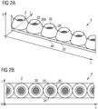
- the lens arrangement 4 comprises a plurality of lenses 2, which are lined up one behind the other along a line or along a straight line.
- the entire lens arrangement 4 is, for example, formed in one piece and consists of plastic.
- each lens 2 includes an elevation 200, which tapers in a first direction V, away from the exit surface 23 or underside 40.
- each lens 2 includes a first recess 20.
- the first recess 20 extends into the lens 2 up to a first bottom surface 22.
- the elevations 200 are each completely laterally surrounded and limited by an outer wall 25 of the elevations 200.
- the outer wall 25 completely surrounds the recess 20 laterally.
- the lateral directions L are directions perpendicular to the first direction V.
- a height of the outer wall 25, measured along the first direction V, has at least 70% of the height of the entire lens 2 everywhere around the recess 20.
- FIG 2B is the lens arrangement 4 of Figure 2A shown in top view. It can be seen that the first Bottom surfaces 22 of the lenses 2 are each circular. The first floor surfaces 22, for example, run essentially perpendicular to the first direction V.
- first recesses 20 are delimited by first inner walls 24.
- the first inner walls 24 have the shape of a lateral surface of a truncated cone.
- the first bottom surface 22 and the first inner wall 24 form parts of an entrance surface 22, 24 of the lens 2, through which light enters the lens 2 during operation.
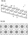
- a lens arrangement 4 which comprises two rows of lenses 2 each arranged along a straight line.
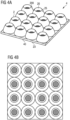
- FIG. 4A Another lens arrangement 4 is shown, in which the lenses 2 are arranged laterally next to one another in a square matrix pattern.
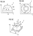
- the first recess 20 extends from a first opening 21 in the direction of the exit surface 23 and ends at a first floor surface 22. In the lateral direction L, the first recess 20 is delimited by a first inner wall 24, which extends transversely to the first floor surface 22.
- the first floor surface 22 is essentially flat and smooth.
- the first recess 20 tapers towards the first bottom surface 22.
- the first recess 20 has the shape of an inverted truncated cone.
- the elevation 200 of the lens 2 is limited by the outer wall 25.
- the outer wall 25 has a convex curvature. This proves to be particularly advantageous for the desired total reflection.
- the exit surface 23 of the lens 2 is flat in this example.
- FIG. 5B and 5C is the lens 2 of the Figure 5A shown in top view and in perspective view. It can be seen that the outer wall 25, the first bottom surface 22 and the first inner wall 24 are formed rotationally symmetrically with respect to an axis 10 through the first recess 20. The axis 10 is parallel to the first direction V.
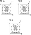
- FIG. 6A to 6C Top views of a lens 2 are shown, the first bottom surface 22 of the lens 2 being provided with microlenses.
- the microlenses are each spherical caps that are in the Figure 6A in a radially symmetrical pattern, in which Figure 6B in a hexagonal pattern and in the Figure 6C are arranged in a square pattern.
- a targeted structuring of the first bottom surface 22 with such microlenses can be used with all lenses 2 described here.
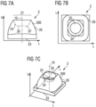
- FIG. 7A to 7C is an exemplary embodiment of a further lens 2, such as that shown here Lens arrangements 4 described can be used, shown in various illustrations.
- the lens 2 hardly differs from the lens 2 of the Figure 5A .
- the first recesses 20 are designed the same.
- the outer wall 25 of the survey 200 in the Figure 7A but differs from that of
- FIG. 5A When looking at the top view of the Figure 7B and the perspective view of the Figure 7C It can be seen that the outer wall 25 has no rotational symmetry with respect to an axis 10 through the first recess 20, but only a 4-fold rotational symmetry. In the top view of the Figure 7B When viewed, the outer wall 25 essentially has the contour of a square with rounded corners.
- FIGS 8A to 8D Cross-sectional views of various lenses 2 are shown, for example viewed in the CO plane. All lenses Figures 8A to 8D can be used in the lens arrangements 4 described here. The lenses 2 differ Figures 8A to 8D with regard to the exit surface 23. The exit surfaces 23 of Figures 8A to 8D can, for example, in the lenses 2 previously described Figures 5A to 7C be used.
- a second recess 26 according to claim 1 of the invention is provided in the area of the exit surface 23 of the lens 2.
- the second recess 26 extends from a second opening 27 towards the first recess 20 and ends at a second bottom surface 28.
- the second recess 26 is delimited by a second inner wall 29.
- the second bottom surface 28 is convexly curved.
- the exit surface 23 of the lens 2 is formed both by the second bottom surface 28 and by the second inner wall 29. The convex curvature of the second bottom surface 28 ensures additional bundling of the light emerging from the lens 2 in the area of the second bottom surface 28.
- the shape of the second recess 26 or the shape of the second bottom surface 28 and the second inner wall 29 is rotationally symmetrical with respect to an axis 10 through the first recess 20 and through the second recess 26.
- the axis 10 runs parallel to the first direction V.
- the from the lens 2 generated light distribution can in particular be symmetrical with respect to the axis 10.
- the light intensity distribution generated by the lens 2 in the CO plane shown here can be the same as the light intensity distribution generated by the lens 2 in the C90 plane.
- the exit surface of the lens 2 is provided with linear structures 230.
- the linear structures 230 are a central notch and grooves arranged on both sides of the central notch.
- the middle notch is V-shaped and includes two notch surfaces that converge in the first direction V and intersect at a notch edge.
- the structures 230 of the exit surface 23 are mirror-symmetrical with respect to a surface 11 running through the first recess 20 and the second recess 26.
- the light intensity distribution curve generated by the lens 2 in the CO plane shown here can therefore be mirror-symmetrical to the surface be 11.
- area 11 coincides with the C90 level.
- the exit surface 23 has no rotational symmetry or rotational symmetry with respect to an axis through the first recess 20 and the second recess 26.
- the shape of the lens 2 in the CO plane shown here is different than in the C90 plane. Accordingly, the light distribution generated by the lens 2 in the CO plane and C90 plane can also be different.
- a second recess 26 according to claim 1 of the invention is again provided in the area of the exit surface 23.
- the second recess 26 has no mirror symmetry in the CO plane shown. Therefore, the light intensity distribution of the CO plane shown here generated by the lens 2 can be asymmetrical.
- the cross-sectional shape of the lens corresponds to 2 Figure 8D but the form as it is in the Figure 8B is shown. In the C90 plane, a light intensity distribution of the lens 2 can therefore be symmetrical.
- a lens arrangement 4 is shown, in which a plurality of lenses 2, for example lenses 2 as shown in the Figure 8C are shown, are lined up along a straight line.
- the linear structures 230 on the underside 40 extend along the straight line across a plurality of the lenses 2. If one looks at the underside 40 of the lens arrangement 4 in a cross-sectional view perpendicular to the straight line and shifts the cross-sectional view along the straight line, the shape of the underside 40 remains essentially the same. In other words, the shape of the underside 40 remains the same Lens arrangement 4 along the straight line within the manufacturing tolerance is the same.
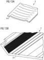
- Edge regions 42 of lens arrangements 4 are shown in detail.
- the edge region 42 delimits the lens arrangement 4 in the lateral direction L, is designed to be coherent and surrounds all lenses 2 of the lens arrangement 4.
- the height or thickness of the edge region 42 is smaller than that of the lens 2.
- the edge regions 42 shown can be used with all previously described lenses 2 can be combined.
- the Figures 10A to 10E are sectional views, for example in a CO level or C90 level.
- the contour of the edge area 42 is in the Figures 10A and 10B that of a rectangle.
- the contour of the edge area is that of a parallelogram with a descending or ascending edge.
- the contour of the edge region 42 in the C0 plane has the shape of an “L” tilted towards the optical axis.
- FIG. 11A 1A is again shown in a cross-sectional view, for example in a CO plane.
- the cover 5 is divided into a central area 50 and two edge areas 51 on both sides.
- the central region 50 covers all light sources 1.
- the edge regions 51 do not cover the light sources 1 in a plan view of the cover 5.
- the cover 5 includes a wave structure 510, which is designed so that the light striking the cover 5 in the edge region 51 in one hits the surface at a sharper angle than would be the case with a flat surface in order to reduce reflection losses.
- the lighting module Figure 11B differs from the light module Figure 11A because in the Figure 11B a lens arrangement 4 with a single row of lenses 2 instead of two rows of lenses 2 is used.
- a lighting module is shown in a cross-sectional view, in which the edge regions 51 of the cover are bent relative to the central region 50 of the cover in the direction of an entry side facing the light sources 1.
- the middle area 50 is structured on the entry side.
- the entry side in the central region 50 has the shape of a Fresnel lens 511.
- the edge regions 51 are linearly structured.
- the structures have the shape of spikes and/or grooves.
- the covers 5 can be designed to be transparent and/or scattering.
Claims (14)
- Module d'éclairage comprenant- une disposition de lentilles (4) avec plusieurs lentilles (2) disposées latéralement les unes à côté des autres,- plusieurs sources de lumière (1) disposées latéralement les unes à côté des autres, qui, lors du fonctionnement, émettant chacune de la lumière en direction de la disposition de lentilles (4), dans lequel- les lentilles (2) comprennent chacune une face d'entrée (22, 24) et une face de sortie (23), dans lequel la face d'entrée (22, 24) est disposée en aval de la face de sortie (23) respectivement dans une première direction,- les lentilles (2) comprennent chacune une saillie (200) se rétrécissant dans la première direction, avec une paroi externe (25) circulaire latérale,- dans la partie de la saillie (200) opposée à la face de sortie (23), est réalisé respectivement un premier évidement (20) dans la saillie (200),- la paroi externe (25) entoure entièrement l'évidement (20) respectivement de manière latérale,- une hauteur, mesurée le long de la première direction, de la paroi externe (25) représente, partout autour de l'évidement (20), respectivement au moins 50 % de la hauteur de la lentille (2) entière,- les faces de sortie (23) des lentilles (2) sont constituées d'un côté inférieur (40) continu de la disposition de lentilles (4),- exactement une lentille (2) est disposée en aval de chaque source de lumière (1),- la saillie (200) de chaque lentille (2) s'étend en direction de la source de lumière (1), de sorte que les premiers évidements (20) sont orientés respectivement vers les sources de lumière (1),- le module d'éclairage est conçu de sorte que la lumière sortant d'une source de lumière (1) entre au niveau du premier évidement (20) dans la lentille (2) disposée en aval, la partie de la lumière arrivant sur la paroi externe (25) de la lentille (2) est réfléchie en grande partie et la lumière est découplée par la face de sortie (23),- les lentilles (2) de la disposition de lentilles (4) comprennent chacune, au niveau de la face de sortie (23), un deuxième évidement (26), qui s'étend à partir d'une deuxième ouverture (27) dans lentille (2) correspondante jusqu'à une deuxième face inférieure (28),- le deuxième évidement (26) est délimité, dans la direction latérale, par une deuxième paroi interne (29) de la lentille (2) correspondante,- la face de sortie (23) de la lentille (2) correspondante (2) comprend la deuxième face inférieure (28) et la deuxième paroi interne (29),- l'extension latérale du deuxième évidement (26) diminue à partie de la deuxième ouverture (27) en direction de la deuxième face inférieure (28),- la deuxième face inférieure (28) est une face incurvée de manière convexe, caractérisé en ce que- le module d'éclairage comprend une plaque de recouvrement translucide (5) qui est disposée à une certaine distance des lentilles (2),- lors du fonctionnement, la lumière découplée par les faces de sortie (23) arrive sur la plaque de recouvrement (5),- dans lequel la plaque de recouvrement (5) est structurée, dans une partie centrale (50), qui recouvre, en vue de dessus de la plaque de recouvrement (5), les sources de lumière (1), afin d'obtenir une focalisation supplémentaire de la lumière sortant de la lentille.
- Module d'éclairage selon la revendication 1, dans lequel- le premier évidement (20) d'une lentille (2) s'étend à partir d'une première ouverture (21) dans la lentille (2) jusqu'à une première face inférieure (22) de la lentille (2),- le premier évidement (20) est délimité, dans la direction latérale, par une première paroi interne (24) de la lentille (2),- la face d'entrée (22, 24) de la lentille (2) comprend la première face inférieure (22) et la première paroi interne (24),- la paroi externe (25) se superpose, dans une direction opposée à la première direction, avec la première ouverture (21), la première paroi interne (24) et la première face inférieure (22) et dépasse de la première face inférieure (22),- une extension latérale du premier évidement (20) diminue respectivement à partir de la première ouverture (21) en direction de la première face inférieure (22).
- Module d'éclairage selon la revendication 1 ou 2,
dans lequel la paroi externe (25) d'une lentille (2) est incurvée de manière convexe. - Module d'éclairage selon l'une des revendications précédentes,
dans lequel la paroi externe (25) d'une lentille (2) est symétrique en rotation par rapport à un axe traversant le premier évidement (20). - Module d'éclairage selon l'une des revendications précédentes,
dans lequel la paroi externe (25) d'une lentille (2) présente une symétrie de révolution d'ordre n lors d'une rotation autour d'un axe traversant le premier évidement (20), dans lequel n est un nombre entier supérieur ou égal à 2. - Module d'éclairage selon l'une des revendications précédentes,
dans lequel la face de sortie (23) d'une lentille (2) est plane dans le cadre de la tolérance de fabrication. - Module d'éclairage selon l'une des revendications précédentes,
dans lequel la deuxième paroi interne (29) et/ou la deuxième face inférieure (28) est symétrique en rotation par rapport à un axe traversant le deuxième évidement (26). - Module d'éclairage selon l'une des revendications 1 à 6,
dans lequel la deuxième face inférieure (28) est conçue, en vue de dessus de la deuxième face inférieure (28), sous la forme d'un demi-cercle ou d'un segment de cercle. - Module d'éclairage selon l'une des revendications précédentes,
dans lequel la face de sortie (23) d'une lentille (2) est munie de structures (230) s'étendant de manière linéaire. - Module d'éclairage selon l'une des revendications précédentes,
dans lequel la disposition de lentilles (4) est réalisée d'une seule pièce. - Module d'éclairage selon la revendication 9, dans lequel- plusieurs lentilles (2) sont disposées le long d'une ligne,- les structures linéaires (230) s'étendent sur les lentilles (2) disposées en ligne, de sorte que la forme géométrique du côté inférieur (40) de la disposition de lentilles (4) ne varie pas le long de la ligne dans le cadre de la tolérance de fabrication.
- Module d'éclairage selon l'une des revendications précédentes,
comprenant une zone de bord (42) délimitant latéralement la disposition de lentilles (4), dans lequel- la zone de bord (42) est continue et entoure toutes lentilles (2) latéralement,- la zone de bord (42) est plus mince que les lentilles (2),- la zone de bord (42) est conçue pour dévier la lumière entrant dans la zone de bord (42) par réfraction et/ou réflexion totale. - Module d'éclairage selon l'une des revendications précédentes,
dans lequel les lentilles (2) sont disposées par rapport aux sources de lumière (1) de sorte qu'au moins 90 % de la lumière émise par une source de lumière (1) est émise vers le premier évidement (20) de la lentille (2) correspondante. - Module d'éclairage selon l'une des revendications précédentes
dans lequel la plaque de recouvrement (5) comprend, dans une zone de bord (51), qui ne se superpose pas, dans une vue de dessus de la plaque de recouvrement (5), avec les sources de lumière (1), des structures permettant de dévier la lumière guidée vers la zone de bord (51) de la plaque de recouvrement (5).
Applications Claiming Priority (1)
| Application Number | Priority Date | Filing Date | Title |
|---|---|---|---|
| DE102017125230.4A DE102017125230A1 (de) | 2017-10-27 | 2017-10-27 | Linse, linsenanordnung und leuchtmodul |
Publications (3)
| Publication Number | Publication Date |
|---|---|
| EP3477189A1 EP3477189A1 (fr) | 2019-05-01 |
| EP3477189B1 true EP3477189B1 (fr) | 2023-09-27 |
| EP3477189C0 EP3477189C0 (fr) | 2023-09-27 |
Family
ID=63965368
Family Applications (1)
| Application Number | Title | Priority Date | Filing Date |
|---|---|---|---|
| EP18202016.4A Active EP3477189B1 (fr) | 2017-10-27 | 2018-10-23 | Module lumineux |
Country Status (2)
| Country | Link |
|---|---|
| EP (1) | EP3477189B1 (fr) |
| DE (1) | DE102017125230A1 (fr) |
Families Citing this family (3)
| Publication number | Priority date | Publication date | Assignee | Title |
|---|---|---|---|---|
| CN110886983A (zh) * | 2019-11-07 | 2020-03-17 | 赛尔富电子有限公司 | 一种照明灯 |
| IT202100023114A1 (it) * | 2021-09-07 | 2023-03-07 | Sideis S R L | Dispositivo e sistema di illuminazione per gallerie stradali |
| WO2023084101A1 (fr) * | 2021-11-15 | 2023-05-19 | Zumtobel Lighting Gmbh | Élément optique et appareil d'éclairage équipé de celui-ci |
Family Cites Families (8)
| Publication number | Priority date | Publication date | Assignee | Title |
|---|---|---|---|---|
| DE2201574A1 (de) * | 1972-01-13 | 1973-07-19 | Siemens Ag | Signalleuchte |
| WO2009016586A1 (fr) * | 2007-08-02 | 2009-02-05 | Koninklijke Philips Electronics N.V. | Collimateur à réflexion interne totale avec uniformité améliorée |
| US20090128921A1 (en) * | 2007-11-15 | 2009-05-21 | Philips Solid-State Lighting Solutions | Led collimator having spline surfaces and related methods |
| US9360190B1 (en) * | 2012-05-14 | 2016-06-07 | Soraa, Inc. | Compact lens for high intensity light source |
| DE102013021053B4 (de) * | 2013-12-18 | 2018-03-01 | Erco Gmbh | Leuchte |
| US20150192257A1 (en) * | 2014-01-07 | 2015-07-09 | Cree, Inc. | Narrow-beam optic and lighting system using same |
| DE102015204665A1 (de) * | 2015-03-16 | 2016-09-22 | Zumtobel Lighting Gmbh | Optisches Element zur Beeinflussung der Lichtabgabe von Leuchtmitteln |
| DE102016207143A1 (de) * | 2016-04-27 | 2017-11-02 | Zumtobel Lighting Gmbh | Leuchtenoptik |
-
2017
- 2017-10-27 DE DE102017125230.4A patent/DE102017125230A1/de active Pending
-
2018
- 2018-10-23 EP EP18202016.4A patent/EP3477189B1/fr active Active
Also Published As
| Publication number | Publication date |
|---|---|
| EP3477189A1 (fr) | 2019-05-01 |
| DE102017125230A1 (de) | 2019-05-02 |
| EP3477189C0 (fr) | 2023-09-27 |
Similar Documents
| Publication | Publication Date | Title |
|---|---|---|
| DE102009017495B4 (de) | Beleuchtungseinrichtung | |
| EP3477189B1 (fr) | Module lumineux | |
| DE60205806T2 (de) | Linse für Leuchtdioden | |
| EP2507542B1 (fr) | Appareil d'éclairage, et dispositif d'éclairage de voie de circulation | |
| DE102004026530B3 (de) | Optikkörper | |
| EP2344362B1 (fr) | Élément de guidage de lumière pour dispositif d'éclairage | |
| DE102013204476B4 (de) | Optisches Element und optoelektronisches Bauelement mit optischem Element | |
| EP1881258B1 (fr) | Unité d'éclairage dotée d'une diode à corps de changement de direction de la lumière intégré | |
| DE102014112891B4 (de) | Optisches Element und optoelektronisches Bauelement | |
| EP2556394B1 (fr) | Module d'éclairage et dispositif d'éclairage à module d'éclairage | |
| DE112016000316B4 (de) | Optoelektronisches Bauelement | |
| EP3023689B1 (fr) | Dispositif d'éclairage | |
| WO2012119812A1 (fr) | Composant à semi-conducteur optoélectronique | |
| EP3477193B1 (fr) | Couvercle pour un module lumineux et module lumineux | |
| EP3477192B1 (fr) | Couvercle pour un module lumineux, module lumineux et luminaire | |
| WO2018096041A1 (fr) | Élément structural doté d'un composant optoélectronique | |
| WO2018215435A2 (fr) | Capteur et biocapteur | |
| DE102017125212B4 (de) | Linse und leuchtmodul | |
| DE102018128124B4 (de) | Optik | |
| WO2016075256A1 (fr) | Composant optoélectronique et dispositif d'éclairage | |
| EP2348250B1 (fr) | Lampe à DEL linéaire, notamment lampe annulaire à DEL | |
| EP1685348B2 (fr) | Lampe a element de sortie de lumiere transparent | |
| EP1900998B1 (fr) | Réflecteur doté d'une structure émettant de la lumière | |
| EP1411294B1 (fr) | Réflecteur avec une surface structurée et luminaire ou système d'éclairage indirect comprenant un tel réflecteur | |
| DE102012209013B4 (de) | Optisches Element und ein Leuchtmodul |
Legal Events
| Date | Code | Title | Description |
|---|---|---|---|
| PUAI | Public reference made under article 153(3) epc to a published international application that has entered the european phase |
Free format text: ORIGINAL CODE: 0009012 |
|
| STAA | Information on the status of an ep patent application or granted ep patent |
Free format text: STATUS: THE APPLICATION HAS BEEN PUBLISHED |
|
| AK | Designated contracting states |
Kind code of ref document: A1 Designated state(s): AL AT BE BG CH CY CZ DE DK EE ES FI FR GB GR HR HU IE IS IT LI LT LU LV MC MK MT NL NO PL PT RO RS SE SI SK SM TR |
|
| AX | Request for extension of the european patent |
Extension state: BA ME |
|
| STAA | Information on the status of an ep patent application or granted ep patent |
Free format text: STATUS: REQUEST FOR EXAMINATION WAS MADE |
|
| 17P | Request for examination filed |
Effective date: 20190703 |
|
| RBV | Designated contracting states (corrected) |
Designated state(s): AL AT BE BG CH CY CZ DE DK EE ES FI FR GB GR HR HU IE IS IT LI LT LU LV MC MK MT NL NO PL PT RO RS SE SI SK SM TR |
|
| RAP1 | Party data changed (applicant data changed or rights of an application transferred) |
Owner name: SITECO GMBH |
|
| REG | Reference to a national code |
Ref country code: DE Ref legal event code: R079 Ref document number: 502018013313 Country of ref document: DE Free format text: PREVIOUS MAIN CLASS: F21V0005000000 Ipc: F21S0004280000 Ref country code: DE Ref legal event code: R079 Free format text: PREVIOUS MAIN CLASS: F21V0005000000 Ipc: F21S0004280000 |
|
| STAA | Information on the status of an ep patent application or granted ep patent |
Free format text: STATUS: EXAMINATION IS IN PROGRESS |
|
| RIC1 | Information provided on ipc code assigned before grant |
Ipc: F21S 4/28 20160101AFI20210517BHEP Ipc: F21V 5/02 20060101ALI20210517BHEP Ipc: F21V 17/16 20060101ALI20210517BHEP Ipc: G02B 19/00 20060101ALI20210517BHEP Ipc: F21V 5/00 20180101ALI20210517BHEP Ipc: F21Y 115/10 20160101ALI20210517BHEP Ipc: F21V 5/04 20060101ALI20210517BHEP Ipc: G02B 3/08 20060101ALI20210517BHEP Ipc: F21V 7/00 20060101ALI20210517BHEP |
|
| 17Q | First examination report despatched |
Effective date: 20210610 |
|
| STAA | Information on the status of an ep patent application or granted ep patent |
Free format text: STATUS: EXAMINATION IS IN PROGRESS |
|
| GRAP | Despatch of communication of intention to grant a patent |
Free format text: ORIGINAL CODE: EPIDOSNIGR1 |
|
| STAA | Information on the status of an ep patent application or granted ep patent |
Free format text: STATUS: GRANT OF PATENT IS INTENDED |
|
| INTG | Intention to grant announced |
Effective date: 20230411 |
|
| GRAS | Grant fee paid |
Free format text: ORIGINAL CODE: EPIDOSNIGR3 |
|
| GRAA | (expected) grant |
Free format text: ORIGINAL CODE: 0009210 |
|
| STAA | Information on the status of an ep patent application or granted ep patent |
Free format text: STATUS: THE PATENT HAS BEEN GRANTED |
|
| AK | Designated contracting states |
Kind code of ref document: B1 Designated state(s): AL AT BE BG CH CY CZ DE DK EE ES FI FR GB GR HR HU IE IS IT LI LT LU LV MC MK MT NL NO PL PT RO RS SE SI SK SM TR |
|
| REG | Reference to a national code |
Ref country code: GB Ref legal event code: FG4D Free format text: NOT ENGLISH |
|
| REG | Reference to a national code |
Ref country code: CH Ref legal event code: EP |
|
| REG | Reference to a national code |
Ref country code: DE Ref legal event code: R096 Ref document number: 502018013313 Country of ref document: DE |
|
| REG | Reference to a national code |
Ref country code: IE Ref legal event code: FG4D Free format text: LANGUAGE OF EP DOCUMENT: GERMAN |
|
| REG | Reference to a national code |
Ref country code: NO Ref legal event code: T2 Effective date: 20230927 |
|
| U01 | Request for unitary effect filed |
Effective date: 20231024 |
|
| U07 | Unitary effect registered |
Designated state(s): AT BE BG DE DK EE FI FR IT LT LU LV MT NL PT SE SI Effective date: 20231030 |
|
| U20 | Renewal fee paid [unitary effect] |
Year of fee payment: 6 Effective date: 20231114 |
|
| PG25 | Lapsed in a contracting state [announced via postgrant information from national office to epo] |
Ref country code: GR Free format text: LAPSE BECAUSE OF FAILURE TO SUBMIT A TRANSLATION OF THE DESCRIPTION OR TO PAY THE FEE WITHIN THE PRESCRIBED TIME-LIMIT Effective date: 20231228 |
|
| PGFP | Annual fee paid to national office [announced via postgrant information from national office to epo] |
Ref country code: GB Payment date: 20231023 Year of fee payment: 6 |
|
| PG25 | Lapsed in a contracting state [announced via postgrant information from national office to epo] |
Ref country code: RS Free format text: LAPSE BECAUSE OF FAILURE TO SUBMIT A TRANSLATION OF THE DESCRIPTION OR TO PAY THE FEE WITHIN THE PRESCRIBED TIME-LIMIT Effective date: 20230927 Ref country code: HR Free format text: LAPSE BECAUSE OF FAILURE TO SUBMIT A TRANSLATION OF THE DESCRIPTION OR TO PAY THE FEE WITHIN THE PRESCRIBED TIME-LIMIT Effective date: 20230927 Ref country code: GR Free format text: LAPSE BECAUSE OF FAILURE TO SUBMIT A TRANSLATION OF THE DESCRIPTION OR TO PAY THE FEE WITHIN THE PRESCRIBED TIME-LIMIT Effective date: 20231228 |
|
| PGFP | Annual fee paid to national office [announced via postgrant information from national office to epo] |
Ref country code: NO Payment date: 20231026 Year of fee payment: 6 Ref country code: CH Payment date: 20231102 Year of fee payment: 6 |
|
| PG25 | Lapsed in a contracting state [announced via postgrant information from national office to epo] |
Ref country code: IS Free format text: LAPSE BECAUSE OF FAILURE TO SUBMIT A TRANSLATION OF THE DESCRIPTION OR TO PAY THE FEE WITHIN THE PRESCRIBED TIME-LIMIT Effective date: 20240127 |