EP3476301A1 - Instrument chirurgical de suture - Google Patents
Instrument chirurgical de suture Download PDFInfo
- Publication number
- EP3476301A1 EP3476301A1 EP18203330.8A EP18203330A EP3476301A1 EP 3476301 A1 EP3476301 A1 EP 3476301A1 EP 18203330 A EP18203330 A EP 18203330A EP 3476301 A1 EP3476301 A1 EP 3476301A1
- Authority
- EP
- European Patent Office
- Prior art keywords
- needle
- surgical
- end effector
- firing stroke
- surgical suturing
- Prior art date
- Legal status (The legal status is an assumption and is not a legal conclusion. Google has not performed a legal analysis and makes no representation as to the accuracy of the status listed.)
- Withdrawn
Links
Images


Classifications
-
- A—HUMAN NECESSITIES
- A61—MEDICAL OR VETERINARY SCIENCE; HYGIENE
- A61B—DIAGNOSIS; SURGERY; IDENTIFICATION
- A61B17/00—Surgical instruments, devices or methods, e.g. tourniquets
- A61B17/28—Surgical forceps
- A61B17/29—Forceps for use in minimally invasive surgery
-
- A—HUMAN NECESSITIES
- A61—MEDICAL OR VETERINARY SCIENCE; HYGIENE
- A61B—DIAGNOSIS; SURGERY; IDENTIFICATION
- A61B17/00—Surgical instruments, devices or methods, e.g. tourniquets
- A61B17/04—Surgical instruments, devices or methods, e.g. tourniquets for suturing wounds; Holders or packages for needles or suture materials
- A61B17/0469—Suturing instruments for use in minimally invasive surgery, e.g. endoscopic surgery
-
- A—HUMAN NECESSITIES
- A61—MEDICAL OR VETERINARY SCIENCE; HYGIENE
- A61B—DIAGNOSIS; SURGERY; IDENTIFICATION
- A61B17/00—Surgical instruments, devices or methods, e.g. tourniquets
- A61B17/04—Surgical instruments, devices or methods, e.g. tourniquets for suturing wounds; Holders or packages for needles or suture materials
- A61B17/0482—Needle or suture guides
-
- A—HUMAN NECESSITIES
- A61—MEDICAL OR VETERINARY SCIENCE; HYGIENE
- A61B—DIAGNOSIS; SURGERY; IDENTIFICATION
- A61B17/00—Surgical instruments, devices or methods, e.g. tourniquets
- A61B17/28—Surgical forceps
- A61B17/29—Forceps for use in minimally invasive surgery
- A61B17/2909—Handles
-
- A—HUMAN NECESSITIES
- A61—MEDICAL OR VETERINARY SCIENCE; HYGIENE
- A61B—DIAGNOSIS; SURGERY; IDENTIFICATION
- A61B18/00—Surgical instruments, devices or methods for transferring non-mechanical forms of energy to or from the body
- A61B18/04—Surgical instruments, devices or methods for transferring non-mechanical forms of energy to or from the body by heating
- A61B18/12—Surgical instruments, devices or methods for transferring non-mechanical forms of energy to or from the body by heating by passing a current through the tissue to be heated, e.g. high-frequency current
- A61B18/14—Probes or electrodes therefor
- A61B18/1442—Probes having pivoting end effectors, e.g. forceps
- A61B18/1445—Probes having pivoting end effectors, e.g. forceps at the distal end of a shaft, e.g. forceps or scissors at the end of a rigid rod
-
- A—HUMAN NECESSITIES
- A61—MEDICAL OR VETERINARY SCIENCE; HYGIENE
- A61B—DIAGNOSIS; SURGERY; IDENTIFICATION
- A61B34/00—Computer-aided surgery; Manipulators or robots specially adapted for use in surgery
- A61B34/30—Surgical robots
-
- A—HUMAN NECESSITIES
- A61—MEDICAL OR VETERINARY SCIENCE; HYGIENE
- A61B—DIAGNOSIS; SURGERY; IDENTIFICATION
- A61B17/00—Surgical instruments, devices or methods, e.g. tourniquets
- A61B2017/00017—Electrical control of surgical instruments
-
- A—HUMAN NECESSITIES
- A61—MEDICAL OR VETERINARY SCIENCE; HYGIENE
- A61B—DIAGNOSIS; SURGERY; IDENTIFICATION
- A61B17/00—Surgical instruments, devices or methods, e.g. tourniquets
- A61B2017/00017—Electrical control of surgical instruments
- A61B2017/00022—Sensing or detecting at the treatment site
- A61B2017/00026—Conductivity or impedance, e.g. of tissue
-
- A—HUMAN NECESSITIES
- A61—MEDICAL OR VETERINARY SCIENCE; HYGIENE
- A61B—DIAGNOSIS; SURGERY; IDENTIFICATION
- A61B17/00—Surgical instruments, devices or methods, e.g. tourniquets
- A61B2017/00017—Electrical control of surgical instruments
- A61B2017/00022—Sensing or detecting at the treatment site
- A61B2017/00039—Electric or electromagnetic phenomena other than conductivity, e.g. capacity, inductivity, Hall effect
-
- A—HUMAN NECESSITIES
- A61—MEDICAL OR VETERINARY SCIENCE; HYGIENE
- A61B—DIAGNOSIS; SURGERY; IDENTIFICATION
- A61B17/00—Surgical instruments, devices or methods, e.g. tourniquets
- A61B2017/00017—Electrical control of surgical instruments
- A61B2017/00022—Sensing or detecting at the treatment site
- A61B2017/00057—Light
-
- A—HUMAN NECESSITIES
- A61—MEDICAL OR VETERINARY SCIENCE; HYGIENE
- A61B—DIAGNOSIS; SURGERY; IDENTIFICATION
- A61B17/00—Surgical instruments, devices or methods, e.g. tourniquets
- A61B2017/00017—Electrical control of surgical instruments
- A61B2017/00221—Electrical control of surgical instruments with wireless transmission of data, e.g. by infrared radiation or radiowaves
-
- A—HUMAN NECESSITIES
- A61—MEDICAL OR VETERINARY SCIENCE; HYGIENE
- A61B—DIAGNOSIS; SURGERY; IDENTIFICATION
- A61B17/00—Surgical instruments, devices or methods, e.g. tourniquets
- A61B17/00234—Surgical instruments, devices or methods, e.g. tourniquets for minimally invasive surgery
- A61B2017/00292—Surgical instruments, devices or methods, e.g. tourniquets for minimally invasive surgery mounted on or guided by flexible, e.g. catheter-like, means
- A61B2017/003—Steerable
- A61B2017/00318—Steering mechanisms
- A61B2017/00323—Cables or rods
- A61B2017/00327—Cables or rods with actuating members moving in opposite directions
-
- A—HUMAN NECESSITIES
- A61—MEDICAL OR VETERINARY SCIENCE; HYGIENE
- A61B—DIAGNOSIS; SURGERY; IDENTIFICATION
- A61B17/00—Surgical instruments, devices or methods, e.g. tourniquets
- A61B2017/00367—Details of actuation of instruments, e.g. relations between pushing buttons, or the like, and activation of the tool, working tip, or the like
- A61B2017/00389—Button or wheel for performing multiple functions, e.g. rotation of shaft and end effector
- A61B2017/00393—Button or wheel for performing multiple functions, e.g. rotation of shaft and end effector with means for switching between functions
-
- A—HUMAN NECESSITIES
- A61—MEDICAL OR VETERINARY SCIENCE; HYGIENE
- A61B—DIAGNOSIS; SURGERY; IDENTIFICATION
- A61B17/00—Surgical instruments, devices or methods, e.g. tourniquets
- A61B2017/00367—Details of actuation of instruments, e.g. relations between pushing buttons, or the like, and activation of the tool, working tip, or the like
- A61B2017/00398—Details of actuation of instruments, e.g. relations between pushing buttons, or the like, and activation of the tool, working tip, or the like using powered actuators, e.g. stepper motors, solenoids
-
- A—HUMAN NECESSITIES
- A61—MEDICAL OR VETERINARY SCIENCE; HYGIENE
- A61B—DIAGNOSIS; SURGERY; IDENTIFICATION
- A61B17/00—Surgical instruments, devices or methods, e.g. tourniquets
- A61B2017/0042—Surgical instruments, devices or methods, e.g. tourniquets with special provisions for gripping
- A61B2017/00424—Surgical instruments, devices or methods, e.g. tourniquets with special provisions for gripping ergonomic, e.g. fitting in fist
-
- A—HUMAN NECESSITIES
- A61—MEDICAL OR VETERINARY SCIENCE; HYGIENE
- A61B—DIAGNOSIS; SURGERY; IDENTIFICATION
- A61B17/00—Surgical instruments, devices or methods, e.g. tourniquets
- A61B2017/0046—Surgical instruments, devices or methods, e.g. tourniquets with a releasable handle; with handle and operating part separable
- A61B2017/00464—Surgical instruments, devices or methods, e.g. tourniquets with a releasable handle; with handle and operating part separable for use with different instruments
-
- A—HUMAN NECESSITIES
- A61—MEDICAL OR VETERINARY SCIENCE; HYGIENE
- A61B—DIAGNOSIS; SURGERY; IDENTIFICATION
- A61B17/00—Surgical instruments, devices or methods, e.g. tourniquets
- A61B2017/0046—Surgical instruments, devices or methods, e.g. tourniquets with a releasable handle; with handle and operating part separable
- A61B2017/00473—Distal part, e.g. tip or head
-
- A—HUMAN NECESSITIES
- A61—MEDICAL OR VETERINARY SCIENCE; HYGIENE
- A61B—DIAGNOSIS; SURGERY; IDENTIFICATION
- A61B17/00—Surgical instruments, devices or methods, e.g. tourniquets
- A61B2017/00681—Aspects not otherwise provided for
- A61B2017/00734—Aspects not otherwise provided for battery operated
-
- A—HUMAN NECESSITIES
- A61—MEDICAL OR VETERINARY SCIENCE; HYGIENE
- A61B—DIAGNOSIS; SURGERY; IDENTIFICATION
- A61B17/00—Surgical instruments, devices or methods, e.g. tourniquets
- A61B17/04—Surgical instruments, devices or methods, e.g. tourniquets for suturing wounds; Holders or packages for needles or suture materials
- A61B2017/0498—Surgical instruments, devices or methods, e.g. tourniquets for suturing wounds; Holders or packages for needles or suture materials for advancing a suture filament along a helical path through tissue
-
- A—HUMAN NECESSITIES
- A61—MEDICAL OR VETERINARY SCIENCE; HYGIENE
- A61B—DIAGNOSIS; SURGERY; IDENTIFICATION
- A61B17/00—Surgical instruments, devices or methods, e.g. tourniquets
- A61B17/04—Surgical instruments, devices or methods, e.g. tourniquets for suturing wounds; Holders or packages for needles or suture materials
- A61B17/06—Needles ; Sutures; Needle-suture combinations; Holders or packages for needles or suture materials
- A61B17/06066—Needles, e.g. needle tip configurations
- A61B2017/06076—Needles, e.g. needle tip configurations helically or spirally coiled
-
- A—HUMAN NECESSITIES
- A61—MEDICAL OR VETERINARY SCIENCE; HYGIENE
- A61B—DIAGNOSIS; SURGERY; IDENTIFICATION
- A61B17/00—Surgical instruments, devices or methods, e.g. tourniquets
- A61B17/28—Surgical forceps
- A61B17/29—Forceps for use in minimally invasive surgery
- A61B2017/2901—Details of shaft
- A61B2017/2902—Details of shaft characterized by features of the actuating rod
- A61B2017/2903—Details of shaft characterized by features of the actuating rod transferring rotary motion
-
- A—HUMAN NECESSITIES
- A61—MEDICAL OR VETERINARY SCIENCE; HYGIENE
- A61B—DIAGNOSIS; SURGERY; IDENTIFICATION
- A61B17/00—Surgical instruments, devices or methods, e.g. tourniquets
- A61B17/28—Surgical forceps
- A61B17/29—Forceps for use in minimally invasive surgery
- A61B2017/2926—Details of heads or jaws
- A61B2017/2927—Details of heads or jaws the angular position of the head being adjustable with respect to the shaft
- A61B2017/2929—Details of heads or jaws the angular position of the head being adjustable with respect to the shaft with a head rotatable about the longitudinal axis of the shaft
-
- A—HUMAN NECESSITIES
- A61—MEDICAL OR VETERINARY SCIENCE; HYGIENE
- A61B—DIAGNOSIS; SURGERY; IDENTIFICATION
- A61B17/00—Surgical instruments, devices or methods, e.g. tourniquets
- A61B17/28—Surgical forceps
- A61B17/29—Forceps for use in minimally invasive surgery
- A61B2017/2926—Details of heads or jaws
- A61B2017/2931—Details of heads or jaws with releasable head
-
- A—HUMAN NECESSITIES
- A61—MEDICAL OR VETERINARY SCIENCE; HYGIENE
- A61B—DIAGNOSIS; SURGERY; IDENTIFICATION
- A61B17/00—Surgical instruments, devices or methods, e.g. tourniquets
- A61B17/28—Surgical forceps
- A61B17/29—Forceps for use in minimally invasive surgery
- A61B2017/2926—Details of heads or jaws
- A61B2017/2932—Transmission of forces to jaw members
- A61B2017/2943—Toothed members, e.g. rack and pinion
-
- A—HUMAN NECESSITIES
- A61—MEDICAL OR VETERINARY SCIENCE; HYGIENE
- A61B—DIAGNOSIS; SURGERY; IDENTIFICATION
- A61B18/00—Surgical instruments, devices or methods for transferring non-mechanical forms of energy to or from the body
- A61B2018/00571—Surgical instruments, devices or methods for transferring non-mechanical forms of energy to or from the body for achieving a particular surgical effect
- A61B2018/00601—Cutting
-
- A—HUMAN NECESSITIES
- A61—MEDICAL OR VETERINARY SCIENCE; HYGIENE
- A61B—DIAGNOSIS; SURGERY; IDENTIFICATION
- A61B18/00—Surgical instruments, devices or methods for transferring non-mechanical forms of energy to or from the body
- A61B2018/00571—Surgical instruments, devices or methods for transferring non-mechanical forms of energy to or from the body for achieving a particular surgical effect
- A61B2018/00607—Coagulation and cutting with the same instrument
-
- A—HUMAN NECESSITIES
- A61—MEDICAL OR VETERINARY SCIENCE; HYGIENE
- A61B—DIAGNOSIS; SURGERY; IDENTIFICATION
- A61B18/00—Surgical instruments, devices or methods for transferring non-mechanical forms of energy to or from the body
- A61B18/04—Surgical instruments, devices or methods for transferring non-mechanical forms of energy to or from the body by heating
- A61B18/12—Surgical instruments, devices or methods for transferring non-mechanical forms of energy to or from the body by heating by passing a current through the tissue to be heated, e.g. high-frequency current
- A61B18/14—Probes or electrodes therefor
- A61B18/1442—Probes having pivoting end effectors, e.g. forceps
- A61B2018/1452—Probes having pivoting end effectors, e.g. forceps including means for cutting
- A61B2018/1457—Probes having pivoting end effectors, e.g. forceps including means for cutting having opposing blades cutting tissue grasped by the jaws, i.e. combined scissors and pliers
-
- A—HUMAN NECESSITIES
- A61—MEDICAL OR VETERINARY SCIENCE; HYGIENE
- A61B—DIAGNOSIS; SURGERY; IDENTIFICATION
- A61B90/00—Instruments, implements or accessories specially adapted for surgery or diagnosis and not covered by any of the groups A61B1/00 - A61B50/00, e.g. for luxation treatment or for protecting wound edges
- A61B90/06—Measuring instruments not otherwise provided for
- A61B2090/064—Measuring instruments not otherwise provided for for measuring force, pressure or mechanical tension
- A61B2090/066—Measuring instruments not otherwise provided for for measuring force, pressure or mechanical tension for measuring torque
-
- A—HUMAN NECESSITIES
- A61—MEDICAL OR VETERINARY SCIENCE; HYGIENE
- A61B—DIAGNOSIS; SURGERY; IDENTIFICATION
- A61B90/00—Instruments, implements or accessories specially adapted for surgery or diagnosis and not covered by any of the groups A61B1/00 - A61B50/00, e.g. for luxation treatment or for protecting wound edges
- A61B90/08—Accessories or related features not otherwise provided for
- A61B2090/0807—Indication means
- A61B2090/0811—Indication means for the position of a particular part of an instrument with respect to the rest of the instrument, e.g. position of the anvil of a stapling instrument
Definitions
- Provisional Patent Application Serial No. 62/665,129 entitled SURGICAL SUTURING SYSTEMS, filed May 1, 2018, of U.S. Provisional Patent Application Serial No. 62/665,134 , entitled SURGICAL CLIP APPLIER, filed May 1, 2018, of U.S. Provisional Patent Application Serial No. 62/665,139 , entitled SURGICAL INSTRUMENTS COMPRISING CONTROL SYSTEMS, filed May 1, 2018, of U.S. Provisional Patent Application Serial No. 62/665,177 , entitled SURGICAL INSTRUMENTS COMPRISING HANDLE ARRANGEMENTS, filed May 1, 2018, and of U.S. Provisional Patent Application Serial No.
- Provisional Patent Application Serial No. 62/649,309 entitled SURGICAL HUB SPATIAL AWARENESS TO DETERMINE DEVICES IN OPERATING THEATER, filed March 28, 2018, of U.S. Provisional Patent Application Serial No. 62/649,310 , entitled COMPUTER IMPLEMENTED INTERACTIVE SURGICAL SYSTEMS, filed March 28, 2018, of U.S. Provisional Patent Application Serial No. 62/649,313 , entitled CLOUD INTERFACE FOR COUPLED SURGICAL DEVICES, filed March 28, 2018, of U.S. Provisional Patent Application Serial No.
- Provisional Patent Application Serial No. 62/578,844 entitled SURGICAL INSTRUMENT WITH MODULAR POWER SOURCES, filed October 30, 2017, and of U.S. Provisional Patent Application Serial No. 62/578,855 , entitled SURGICAL INSTRUMENT WITH SENSOR AND/OR CONTROL SYSTEMS, filed October 30, 2017, the disclosures of which are incorporated by reference herein in their entireties.
- the present disclosure relates to surgical systems and, in various arrangements, to grasping instruments that are designed to grasp the tissue of a patient, dissecting instruments configured to manipulate the tissue of a patient, clip appliers configured to clip the tissue of a patient, and suturing instruments configured to suture the tissue of a patient, among others.
- proximal and distal are used herein with reference to a clinician manipulating the handle portion of the surgical instrument.
- proximal refers to the portion closest to the clinician and the term “distal” refers to the portion located away from the clinician.
- distal refers to the portion located away from the clinician.
- spatial terms such as “vertical”, “horizontal”, “up”, and “down” may be used herein with respect to the drawings.
- surgical instruments are used in many orientations and positions, and these terms are not intended to be limiting and/or absolute.
- Various exemplary devices and methods are provided for performing laparoscopic and minimally invasive surgical procedures.
- the various methods and devices disclosed herein can be used in numerous surgical procedures and applications including, for example, in connection with open surgical procedures.
- the various instruments disclosed herein can be inserted into a body in any way, such as through a natural orifice, through an incision or puncture hole formed in tissue, etc.
- the working portions or end effector portions of the instruments can be inserted directly into a patient's body or can be inserted through an access device that has a working channel through which the end effector and elongate shaft of a surgical instrument can be advanced.
- these surgical suturing instruments comprise, among other things, a shaft, an end effector attached to the shaft, and drive systems positioned within the shaft to transfer motion from a source motion to the end effector.
- the motion source can comprise a manually driven actuator, an electric motor, and/or a robotic surgical system.
- the end effector comprises a body portion, a needle track defined within the body portion, and a needle driver configured to drive a needle through a rotational firing stroke.
- the needle is configured to be guided through its rotational firing stroke within the body portion by the needle track.
- the needle driver is similar to that of a ratchet system.
- the needle driver is configured to drive the needle through a first half of the rotational firing stroke which places the needle in a hand-off position - a position where a tissue-puncturing end of the needle has passed through the target tissue and reentered the body portion of the end effector.
- the needle driver can be returned to its original position to pick up the tissue-puncturing end of the needle and drive the needle through a second half of its rotational firing stroke. Once the needle driver pulls the needle through the second half of its rotational firing stroke, the needle driver is then returned to its original unfired position to grab the needle for another rotational firing stroke.
- the drive systems can be driven by one or more motors and/or manual drive actuation systems.
- the needle comprises suturing material, such as thread, for example, attached thereto.
- the suturing material is configured to be pulled through tissue as the needle is advanced through its rotational firing stroke to seal the tissue and/or attached the tissue to another structure, for example.
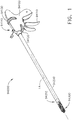
- FIGS. 1-5 depict a surgical suturing instrument 94000 configured to suture the tissue of a patient.
- the surgical suturing instrument 94000 comprises a handle 94100, a shaft 94200 extending distally from the handle 94100, and an end effector 94300 attached to the shaft 94200 by way of an articulation joint 94210.
- the handle 94100 comprises a firing trigger 94110 configured to actuate a firing drive of the surgical suturing instrument 94000, a first rotational actuator 94120 configured to articulate the end effector 94300 about an articulation axis AA defined by the articulation joint 94210, and a second rotational actuator 94130 configured to rotate the end effector 94300 about a longitudinal axis LA defined by the end effector 94300.
- the surgical suturing instrument 94000 further comprises a flush port 94140. Examples of surgical suturing devices, systems, and methods are disclosed in U.S. Patent Application Serial No. 13/832,786 , now U.S. Patent No.
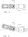
- FIGS. 6-8 depict a needle sensing system 91000 configured to be used with a surgical suturing instrument system.
- the needle sensing system 91000 comprises a resistive sensing circuit configured to allow a control program of a control interface to determine the position of a needle during its firing stroke by monitoring the resistance of the resistive sensing circuit.
- the needle sensing system 91000 comprises a needle sensing circuit 91100 and a needle 91200.
- the needle sensing circuit 91100 comprises a supply portion, or leg, 91110 terminating at a first terminal 91112 and comprising a first resistance R1.
- the needle sensing circuit 91100 further comprises a return portion 91120 comprising a first return leg 91130 terminating at a first return terminal 91132 and a second return leg 91140 terminating a second return terminal 91142.
- the first return leg 91130 and the second return leg 91140 are wired in parallel with respect to each other.
- the first return leg 91130 comprises a second resistance R2 and the second return leg 91140 comprises a third resistance R3.
- the needle 91210 is configured to act as a switch for the needle sensing circuit 91100 by contacting the terminals 91112, 91132, and 91142 during its firing stroke as the needle 91200 moves in a rotational direction to suture tissue.
- the resistance of such a circuit can be monitored by a processor to determine the location of the needle 91200 during its firing stroke.
- the needle 91200 comprises a tip 91213, a butt end 91211, and an arcuate shaft 91212 extending between the tip 91213 and the butt end 91211.
- the needle 91200 further comprises suturing material 91220 attached to the butt end 91211 of the needle 91200.
- the tip 91213 comprises a bevel, or point, 91215 configured to pierce tissue during a firing stroke of the needle 91200.
- the needle 91200 moves through its firing stroke, it is configured to move into and out of contact with the terminals 91112, 91132, and 91142. In its starting, or home, position ( FIG. 6 ), the needle 91200 is in contact with all three terminals 91112, 91132, and 91142.
- the total resistance of the circuit 91100 in this configuration can be detected by the control system of the suturing instrument to identify that the needle 91200 is in its starting position.
- the total resistance of the circuit 91100 in this configuration is shown in the circuit diagram 91000' of FIG. 6 and can be referred to as the starting position resistance.
- the total resistance of the circuit 91100 in this configuration is shown in the circuit diagram 91000' of FIG. 7 and can be referred to as the first partially-fired position resistance.
- the circuit 91100 now comprises a third total resistance that is different from the starting position resistance and the first-partially fired position resistance. This can be referred to as the second partially-fired position resistance ( FIG. 8 ). Because the second partially-fired position resistance is different than the starting position resistance and the first partially-fired position resistance, the second partially-fired position resistance can be detected to determine that the needle 91200 has moved into the second partially-fired position.
- the system 91100 permits the needle location to be detected directly. Monitoring the needle location over a period of time can provide means for determining the rate of advancement of the needle and/or changes in rate of advancement of the needle during its firing stroke. In various instances, if the needle is sensed to be moving at a rate slower than preferred, for example, the instrument can automatically adjust a power control program of the motor which is advancing the needle through its firing stroke to speed up the needle. Similarly, if the needle is sensed to be moving at a rate faster than preferred, for example, the instrument can automatically adjust the power control program of the motor which is advancing the needle through its firing stroke to slow down the needle. This arrangement allows the control program to adapt the rate and/or sequence at which the needle is fired during a procedure and/or during each firing stroke of the needle to better accommodate variable conditions such as, for example, variable tissue thicknesses during suturing.
- FIG. 9 illustrates a logic flow diagram of a process 93800 depicting a control program for controlling a surgical suturing instrument.
- the process 93800 comprises monitoring 93801 a position sensing circuit output.
- the output resistance of the system 91110 can be monitored throughout the operation of a surgical suturing instrument.
- the process 93800 further includes determining 93803 if the control motions applied to the needle need to be adjusted based on the position sensing circuit output.
- a processor for example, can monitor the position sensing circuit output over a period of time and calculate the speed of the needle during its firing stroke. If the speed is too fast or too slow for the present tissue thickness, for example, the control program can adjust 93807 the control motions applied to the needle to change the speed of the needle firing stroke. If the speed of the needle is consistent with a predetermined speed profile for the present tissue thickness, the control program can continue 93805 normal operation of the instrument.
- Other position sensing systems disclosed herein can be used with this process.
- FIG. 10 depicts a needle sensing system 91300 configured to allow a control system of a suturing instrument to monitor the motions of the needle within the end effector against the anticipated, or expected, motions of the needle.
- backlash in a motor-driven needle drive system could cause the drive system to produce a shorter needle stroke than expected for a given amount of motor rotations.
- the needle sensing system 91300 comprises an end effector 91310, a needle track 91312 defined within the end effector 91310, and a needle 91320. Similar to the above, the needle 91320 is configured to be actuated by a needle driver to move the needle 91320 through a circular firing stroke.
- the needle 91320 is guided by the needle track 91312 as the needle 91320 is actuated by the needle driver.
- the needle sensing system 91300 comprises a plurality of sensors 91340 designated as S1, S2, S3, and S4 which, as discussed below, are configured to track the motion of the needle 91320.
- the sensors 91340 may be any suitable position-detecting sensor such that, as the needle 91320 engages, or trips, a sensor 91340, that sensor sends a voltage signal to the control system that the sensor 91340 has detected that the needle 91320 indicating the position of the needle 91320.
- the needle 91320 comprises a tip 91322 that is configured to initially trip the sensors 91340 as the tip 91322 approaches and contacts, or otherwise trips, the sensors 91340.
- the end effector 91310 further comprises a tissue opening 91314 defined therein.
- the end effector 91310 is pressed against the patient tissue such that the tissue enters the opening 91314.
- the tip 91322 can pierce tissue in the opening 91314 and then re-enter the needle track 91312 on the other side of the end effector 91310.
- the needle 91320 is dimensioned to have a larger length than the distance of the opening 91314 so that the needle 91320 can be guided by the needle track 91312 back into the needle track 91312 before a butt end of the needle exits the end effector 91310 into the opening 91314.
- FIG. 11 is a graph 91350 depicting a portion of a needle firing stroke using the needle sensing system 91300 of FIG. 10 .
- FIG. 11 there is an overlap of detection for each neighboring sensor.
- each sensor is configured to detect the tip 91322 of the needle 91320 before the previous sensor no longer detects the needle 91320.
- more than two sensors are configured to sense the needle during the needle firing stroke.
- the sensors 91340 can be used in combination with a control program to ensure that a motor driving the needle 91320 through its firing stroke is driving the needle 91320 the expected amount. For example, a certain amount of rotation from the needle drive motor should produce a corresponding travel length of the needle 91320.
- Monitoring the position of the needle 91320 in the end effector 91310 along with rotational motion of the motor can provide a way to make sure that the motor is producing the anticipated drive motions of the needle.
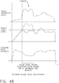
- An example of a needle stroke where the rotational motion of the motor and the actual length of needle travel are monitored is depicted in the graph 91360 illustrated in FIG. 12 .
- the control system can adjust the power delivered to the motor to account for these differences and assure that the needle is being driven all the way around its firing path during a firing stroke. For example, if the motor takes more rotations than expected to cause the needle to travel a certain distance, the control system can increase the number of rotations for the needle to complete the firing stroke. Such instances could be due to backlash in the drive system, for example.
- control program can place the system in a limp mode, for example, to prevent premature failure of components.
- the needle sensing system 91300 can also monitor the current drawn by the needle drive motor while monitoring the input from the sensors 91340.
- a control program can the reverse actuation of the needle 91320 in the event that a substantial increase in current is detected in the motor and the subsequent sensor 91340 has not been tripped - possibly indicating that the needle is jammed.
- an encoder can be used to measure the number of rotations being provided by the motor.
- a control program can compare the number of rotations being provided by the motor to the input from the sensors 91340.
- the control program can interrogate the motor current to assess why the needle is not traveling the expected distance. If the motor current is substantially high, this could indicate a jam, as discussed above. If the motor current is substantially low, this could indicate that the needle and the needle driver are no longer coupled, for example, and that the needle driver is freely moving without driving the needle. In an alternative embodiment, motor torque can be sensed instead of motor current. An example of current monitoring can be seen in the graph 91370 illustrated in FIG. 13 .
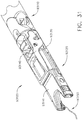
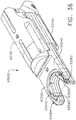
- FIGS. 14-16 depict a surgical suturing instrument 91500 comprising a shaft 91510, an end effector 91530, and a needle drive system 91550.
- the surgical suturing instrument 91500 is designed to provide a suturing bite width that is larger than the diameter of the shaft 91510 by using an expandable/collapsible needle guide element.
- Various suturing devices are limited to a bite width that is constrained by the diameter of their shafts.
- the surgical suturing instrument 91500 comprises a movable needle guide 91560 rotatably mounted to a body 91540 of the end effector 91530 configured to permit the use of a needle 91570, which also comprises a length that exceeds the width of the shaft diameter.
- a linear actuator 91512 connected to a proximal end 91562 of the movable needle guide 91560 is configured to be pushed and pulled to pivot the movable needle guide 91560 about its pivot point 91562.
- FIG. 14 illustrates the movable needle guide 91560 in an expanded configuration where the surgical suturing instrument 91500 is ready to be fired.
- the linear actuator 91512 is pulled proximally.
- the surgical suturing instrument 91500 is in a configuration sufficient to be passed through a trocar.
- the needle drive system 91550 comprises a linear actuator 91520, a proximal needle feed wheel 91552 configured to be rotated about its pivot 91552 by way of the linear actuator 91520 and rotatably mounted within the body 91540 of the end effector 91530, and a distal needle feed wheel 91554 configured to be rotated about its pivot 91555 by a connecting link 91556 by way of the proximal needle feed wheel 91552 and rotatably mounted within the body 91540 of the end effector 91530.
- the feed wheels 91552, 91554 are configured to be rotated together to move the flexible needle 91570 through the body 91540 of the end effector 91530 and out of the body 91540 of the end effector 91530 against the movable needle guide 91560.
- the movable needle guide 91560 comprises a curved tip 91563 configured to guide the flexible needle 91570 back into the body 91540 of the end effector 91530 so that the distal needle feed wheel 91554 can begin guiding the flexible needle 91570 back toward the proximal needle feed wheel 91552.
- the feed wheels 91552, 91554 are connected by a coupler bar such that they rotate at the same time.
- the needle 91570 may need to be repaired or replaced.
- the movable needle guide 91560 may be pivoted outwardly to provide access to the needle 91570 ( FIG. 16 ).
- the needle 91570 comprises an arc length A.
- the distance between the pivots 91553, 91555 of the feed wheels 91552, 91554 is labeled length B.
- the arc length A of the needle 91570 must be greater than the length B in order to be able to guide the flexible needle 91570 back into the end effector body 91540 with the proximal needle feed wheel 91553.
- Such an arrangement allows a capture, or bite, width 91580 of the surgical suturing instrument 91500 to be larger than the diameter of the shaft 91510.
- a portion of the end effector containing the needle drive system 91550 can be articulated relative to the end effector body 91540 so that the capture width, or opening, 91580 can hinge outwardly and face tissue distally with respect to the instrument 91500.
- This arrangement can prevent a user from having to preform the suturing procedure with respect to the side of the instrument 91500.
- Such a feature may utilize a hinge mechanism with snap features to rigidly hold the end effector body 91540 in a firing position as opposed to a position suitable for insertion through a trocar.
- a portion of the end effector 91530 is movable to increase or decrease the width of the end effector 91530. Decreasing the width of the end effector 91530 allows the end effector 91530 to be inserted through a narrow trocar passageway. Increasing the width of the end effector 91530 after it has been passed through the trocar allows the end effector 91530 to make larger suture loops in the patient tissue, for example.
- the end effector 91530 and/or the needle 91570 can be flexible so that they can be compressed as they are inserted through the trocar and then re-expand once they have passed through the trocar. Such an arrangement, as described above, allows a larger end effector to be used.
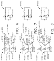
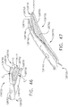
- FIG. 17 depicts a collapsible suturing device 92300 comprising a shaft 92310 and an end effector 92320 configured to be articulated relative to the shaft 92310.
- the device 92300 comprises a tissue bite region having a larger width than its shaft diameter.
- the end effector 92320 is hingedly coupled to the shaft 92310.
- the collapsible suturing device 92300 comprises a separate actuation member to rotate the end effector 92320 relative to the shaft 92310.
- the end effector 92320 can be spring biased into a straight configuration where a user may apply torque to a distal end of the end effector 92320 by pressing the end effector 92320 against tissue to rotate the end effector 92320 relative to the shaft 92310.
- a user may apply torque to a distal end of the end effector 92320 by pressing the end effector 92320 against tissue to rotate the end effector 92320 relative to the shaft 92310.
- a distal-facing tissue bite region 92321 which can permit a user to more accurately and/or easily target tissue to be sutured.
- the tissue bite region 92321 is larger than the diameter of the shaft 92310.
- a user would insert the collapsible suturing device 92300 into a trocar while the device 92300 is in its straight configuration.
- the user may actively rotate the end effector 92320 with an actuator to orient the end effector 92320 properly to prepare to suture the tissue.
- a movable needle guide may be actuated outwardly to prepare to advance the needle through a needle firing stroke. In this configuration, the end effector 92320 can then be pressed against the tissue to be sutured and the needle can be advanced through a needle firing stroke.
- the needle guide can be collapsed and the end effector 92320 can be rotated back into its straight configuration to be removed from the patient through the trocar.
- the needle may be taken out of the end effector 92320 before or after the end effector 92320 has passed back out of the patient through the trocar.
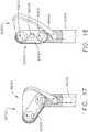
- FIG. 18 depicts a collapsible suturing device 92400 comprising a shaft 92410 and an end effector 92420 attached to the distal end of the shaft 92410.
- the device 92400 comprises a tissue bite region having a larger width than its shaft diameter.
- the end effector 92420 further comprises a needle driving system 92430 configured to drive a flexible needle through a needle firing stroke against a movable needle guide 92440.
- the needle driving system 92430 comprises a proximal feed wheel 92431, a distal feed wheel 92433, and an intermediate feed wheel 92435 configured to feed the flexible needle through the end effector 92420.
- the intermediate feed wheel 92435 permits the use of a longer flexible needle than arrangements without an intermediate feed wheel.
- the intermediate feed wheel is actively connected the needle driving system.
- the intermediate feed wheel is an idler component and rotates freely.
- the needle comprises a width that is larger than the width of the shaft with which is used.
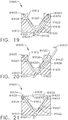
- FIGS. 19-21 depict a surgical suturing end effector 91600 configured to provide a suturing device with a variable needle stroke.
- the needle stroke of the end effector 91600 can be different every time the end effector 91600 is fired.
- the end effector 91600 also can provide a suturing bite width that is wider than the diameter of its shaft.
- the surgical suturing end effector 91600 comprises a body portion 91610 having a tissue-engaging opening 91612, a needle track 91620 defined within the body portion 91610, and a needle 91630 configured to be guided through a firing stroke by the needle track 91620.
- FIG. 19 illustrates the needle 91630 in its parked position where the end effector 91600 can be passed through a trocar.
- the needle 91630 is advanced linearly from a park track portion 91621 of the needle track 91620 - by way of its proximal end 91633 - to a ready-to-fire position ( FIG. 20 ).
- the needle 91630 extends outwardly beyond the body 91610 of the end effector 91600 when the needle 91630 is in its ready-to-fire position.
- the needle 91630 comprises a canoe-like shape but can comprise any suitable shape to achieve this.
- the needle 91630 When a clinician wants to complete a suture stroke, discussed in greater detail below, the needle 91630 is moved to the position shown in FIG. 21 referred to as the hand-off position. To get to this position, the proximal end 91633 of the needle 91630 is rotated and advanced linearly within a first track portion 91622 of the track 91620 until the proximal end 91633 of the needle 91630 reaches a distal end 91623 of the first track portion 91622 and a tip portion 91634 of the needle 91630 engages a distal end 91625 of a second track portion 91624 of the track 91620.
- This engagement allows a needle driver that rotates and linearly advances the needle 91630 within the track 91620 to move along the track 91620 to the distal end 91625 of the second track portion 91624 to grab the tip portion 91634 and pull the needle 91630 through the end effector 91600 by pulling the needle 91630 proximally and rotating the needle 91630 to prepare for a second firing stroke of the needle 91630.
- the needle driver can re-connect, or re-engage, with the proximal end 91633 of the needle 91630 to begin a second firing stroke to return the needle 91630 to its ready-to-fire position illustrated in FIG. 20 .
- the firing stroke of the needle 91630 having a canoe-like shape, can resemble a box-shaped, or diamond-shaped, path.
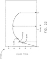
- FIG. 22 is a stress-strain diagram 91700 of the loads experienced by a needle during a firing stroke.
- a control system of a surgical suturing instrument can monitor input from a strain gauge and adjust the operation of the surgical suturing instrument based on the monitored strain and/or display the strain to a user during use.
- the surgical suturing instrument can alert a user when the needle has reached 75% 91701 of its yield strength during a suturing procedure.
- the surgical instrument can provide the clinician with an option to adjust the advancement speed of the needle to help prevent further spikes of the strain and/or stress within the needle. If the needle reaches 100% 91703 of its yield strength, overstress may be reported to the user and the control system will report the overstress to the system disclosed in U.S. Patent Application Serial No.
- the control program automatically slows the speed and may disable the instrument from actuating the needle any further, and/or request action to be taken before any further use of the surgical suturing instrument.
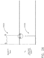
- FIGS. 23 and 24 depict a method for detecting the proper and/or improper attachment of a modular shaft to a surgical instrument handle and/or surgical robot, for example.
- FIG. 23 depicts an attachment assembly 91800 attachable to an attachment interface 91810 - which can be a surgical instrument handle and/or robotic attachment, or control, interface. Monitoring the torque of a drive system coupled at the attachment interface 91810 can provide a way to determine if the attachment interface 91810 and the modular attachment 91820 have been successfully attached or not.
- the solid plot line represents a scenario where an attempt at attaching the modular attachment 91820 to the attachment interface 91810 was made, and the modular attachment 91820 and the attachment 91830 slipped out of engagement thereby causing a reduction in torque of the actuation drive system below a minimum torque threshold representing an unsuccessful attachment and engagement of drive systems.
- the torque of a failed attempt is noticeably different than the torque of a successful attempt which is also illustrated in the graph 91830.
- the current of the motor that drives the drive system can be directly monitored.
- the surgical instrument is equipped with a control system that shuts off the motor in this scenario (1) when the torque sensed drops below the minimum threshold torque.
- the control system can also alert a user that the motor has been stopped because attachment was not successful.
- a second scenario is illustrated by a dashed plot line where attachment is made, however, the torque sensed increases above a maximum torque threshold. This could indicate a jam between the attachment interface 91810 and the modular attachment 91820.
- the surgical instrument is equipped with a control system that limits the torque delivered by the drive system when the torque sensed increases above the maximum threshold torque, as illustrated in the dashed plot line representing the second scenario (2). Such a limiting of torque delivery can prevent the breaking of components in the modular attachment 91820 and/or the attachment interface 91810.
- strain gauges can be fitted to frame elements of the modular attachments to monitor force applied to tissue with the frame elements themselves.
- a strain gauge can be fitted to an outer shaft element to monitor the force experienced by the shaft as the modular attachment is pushed against tissue and/or as the modular attachment pulls tissue. This information can be communicated to the user of the instrument so that the user is aware of the pressure being applied to the tissue by the grounded elements of the modular attachment due to manipulation and movement of the modular attachment within the surgical site.
- FIGS. 25 and 26 depict a surgical instrument system 91910 that is configured to monitor unexpected electrical potential applied to a surgical instrument during an operation that involves using a mono-polar bridge instrument.
- FIG. 25 depicts a system 91910 comprising a grasper 91912 and a mono-polar bridge instrument 91914 being used in the same surgical site.
- the voltage potential of the grasper 91912 can be monitored throughout the use of the system 91910 during an operation.
- Stage (1) of the graph 91920 represents the beginning of articulation of the grasper 91912 using motorized articulation.
- Stage (2) represents a spike in detected voltage potential of the grasper 91912.
- Such a spike in voltage potential can be conducted to the grasper 91912 by way of the mono-polar bridge instrument 91914.
- the system 91910 can automatically reverse the motor direction Stage (3) of articulation to move the grasper 91912 away from the mono-polar bridge instrument 91914 until the unexpected voltage spike subsides Stage (4).
- the control program of the system 91910 can then instruct the articulation motor to automatically reverse the articulation a predetermined amount passed the point when the system 91910 no longer detects the voltage spike to ensure that this voltage spike will not occur again due to minor inadvertent movement of either the grasper 91912 and/or the mono-polar bridge instrument 91914.
- the surgical instrument can also alert the user when an unexpected voltage potential is detected and await further action by a user of the instrument. If the user is using the instrument that experiences the voltage spike as a mono-polar bridge instrument then the user could inform the instrument of this to continue actuation of the instrument.
- the instrument can also include an electrical circuit, or ground path, to interrupt the flow of electricity beyond a dedicated position when the instrument experiences an unexpected voltage potential. In at least one instance, the ground path can extend within a flex circuit extending throughout the shaft.
- FIG. 27 illustrates a logic diagram of a process 93900 depicting a control program for controlling a surgical instrument.
- the process 93900 comprises sensing 93901 an electrical potential applied to the instrument. For example, the voltage of an electrical circuit which includes the instrument can be monitored.
- the process 93900 further includes determining 93903 if the sensed electrical potential is above a predetermined threshold based on the sensed electrical potential.
- a processor for example, can monitor the voltage and, if a voltage spike occurs, the processor can change the operation of the surgical instrument. For instance, the process can adjust 93907 the control motions of the instrument such as reversing a previous motion, for example. If the sensed electrical potential is below the predetermined threshold, the control program can continue 93905 the normal operation of the instrument.
- surgical suturing instruments can include means for detecting the tension of the suture during the suturing procedure. This can be achieved by monitoring the force required to advance a needle through its firing stroke. Monitoring the force required to pull the suturing material through tissue can indicate stitch tightness and/or suture tension. Pulling the suturing material too tight during, for example, tying a knot can cause the suturing material to break.
- the instrument can use the detected forces to communicate stitch tightness to the user during a suturing procedure and let the user know that the stitch is approaching its failure tightness or, on the other hand, is not tight enough to create a sufficient stitch.
- the communicated stitch tightness can be shown to a user during a suturing procedure in an effort to improve the stitch tightness throughout the procedure.
- a surgical suturing instrument comprises a method for detecting load within the end effector, or head, of the instrument, and a control program to monitor this information and automatically modify, and/or adjust, the operation of the instrument.
- a needle holder and/or a needle drive can comprise a strain gauge mounted thereon to monitor the force and stress being experienced by the needle during its firing stroke.
- a processor of the instrument can monitor the strain sensed by the strain gauge by monitoring the voltage reading that the strain gauge provides and, if the force detected is above a predetermined threshold, the processor can slow the needle and/or alert a user of the instrument that the needle is experiencing a force greater than a certain threshold.
- Other parameters such as needle velocity and/or acceleration, for example, can be monitored and used to modify the operation of the surgical instrument.
- FIG. 28 depicts a surgical suturing instrument 92200 comprising a shaft 92210, an end effector 92230, and an articulation joint 92220 attaching the end effector 92230 to the shaft 92210 and permitting articulation of the end effector 92230 relative to the shaft 92210.
- the end effector 92230 comprises a frame 92232 and a suture cartridge 92234.
- the cartridge 92234 comprises a needle 92236 comprising suturing material 92238 attached thereto configured to pass through tissue T.
- Various parameters of the instrument 92200 can be monitored during a surgical suturing procedure.
- the force, or load, experienced by the needle 92236 can be monitored, the torque load that resists distal head rotation of the end effector 92230 can be monitored, and/or the bending load of the shaft 92210 that can cause drive systems within the shaft to bind up can be monitored.
- the monitoring of these parameters is illustrated in the graph 92100 in FIG. 29 .
- the surgical instrument 92200 is configured to limit corresponding motor current if certain thresholds of the parameters are exceeded.
- the force experienced by the needle 92236 is represented by the solid plot line in the graph 92100. This force can directly correspond to the current drawn by the motor that fires the needle 92236.
- the motor that is firing the needle slows down thereby reducing the load on the needle and reducing current through the motor. If this force, or current, exceeds a certain pre-determined threshold, the power applied to the needle firing motor can be limited to prevent possible failure of drive system components and/or driving a needle through an unintended target.
- This limiting event is labeled (1) in the reaction graph 92120.
- the torque load experienced by the end effector 92230 is represented by the dashed plot in the graph 92100. This torque load can be a result of trying to rotate the end effector 92230 while the suturing material 92238 is still connected to tissue T and the needle 92236.
- This torque load can directly correspond to the current of the motor that rotates the end effector 92230. If this torque load, or current, exceeds a certain pre-determined threshold, power to the motor that rotates the end effector 92230 can be limited.
- This limiting event is labeled (2) in the reaction graph 92120.
- the bending load experienced by the shaft 92210 is represented by the dash-dot plot in the graph 92100 and can be sensed by using a strain gauge placed on the shaft 92210, for example. If this bending load exceeds a certain pre-determined threshold, power to the motor that rotates the end effector 92230 can be limited and reduced. This limiting event is labeled (3) in the reaction graph 92120.
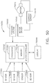
- FIG. 30 illustrates a logic diagram of a process 94000 depicting a control program for controlling a surgical suturing instrument.
- the process 94000 comprises monitoring 94001 one or more detectable parameters of the surgical suturing instrument. For example, the force experienced by the suturing needle, the torque load experienced by the shaft of the instrument, and/or the torque load experienced by the end effector of the instrument can be monitored. In fact, any combination of detectable parameters can be monitored.
- the process 94000 further includes determining 94003 if the detected parameters warrant a change in the operation of the instrument.
- the control program can adjust 94007 the control motions applied to the end effector, such as stopping the actuation of the instrument, until the torque experienced by the shaft falls below the predetermined threshold. If all of the detected parameters are within operational conditions, the control program can continue 94005 the normal operation of the instrument.
- Another system for detecting and/or monitoring the location of the suturing needle during its firing stroke can include utilizing one or more magnets and Hall Effect sensors.
- a permanent magnet can be placed within and/or on the needle and a Hall Effect sensor can be placed within, or adjacent to, the needle track, for example.
- movement of the needle will cause the magnet to move into, within, and/or out of the field created by the Hall Effect sensor thereby providing a way to detect the location of the needle.
- a magnet can be placed on one side of the needle track and a corresponding Hall Effect sensor can be placed on the other side of the needle track.
- the needle itself can interrupt the magnetic field between the magnet and the Hall Effect sensor as the needle passes between the two magnets, thereby providing a way to detect the location of the needle.
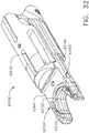
- FIGS. 31 and 32 depict a surgical suturing end effector assembly 93100 configured to suture the tissue of a patient during a surgical suturing procedure.
- the end effector assembly 93100 comprises a shaft 93110 and an end effector 93120 extending distally from the shaft 93110.
- the end effector 93120 comprises a first jaw 93130 and a second jaw 93140 configured to receive a replaceable suturing cartridge 93141 therein.
- the suturing cartridge 93141 comprises a needle 93152 and suture material 93150 attached thereto configured to be driven through a needle firing stroke and guided by a needle track 93142 in the suturing cartridge 93141.
- the surgical suturing end effector assembly 93100 further comprises a needle sensing system comprising a magnet 93162 and a Hall Effect sensor 93164.
- the magnet 93162 and Hall Effect sensor 93164 are positioned within the suturing cartridge 93141 such that the needle 93152 is configured to interrupt the magnetic field between the magnet 93162 and the Hall Effect sensor 93164. Such an interruption can indicate to a control program the position of the needle 93152 relative to the suturing cartridge 93141 and/or within its firing stroke.
- the sensor and magnet may be embedded within the cartridge and/or placed adjacent the needle track such as, for example, on top of, on bottom of, and/or on the sides of the needle track.
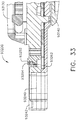
- FIG. 33 depicts a needle sensing system 93200 positioned within a suturing cartridge 93240.
- the suturing cartridge 93240 comprises a needle 93252 and a needle track 93242 configured to guide the needle 93252 through a needle firing stroke.
- the needle sensing system 93200 comprises a magnet 93264 and a Hall Effect sensor 93262 positioned above and below, respectively, the needle track 93242.
- the Hall Effect sensor 93262 and the magnet 93264 are configured to indicate the position of the needle to a control circuit as the needle interrupts the magnetic field between the Hall Effect sensor 93262 and the magnet 93264.
- Such an arrangement can provide a more localized needle position detection system.
- a suturing cartridge can contain more than one Hall Effect sensor and magnet arranged in this manner to provide multiple detection locations along the needle track. That said, any suitable sensor arrangement can be used.
- a control program can determine the position of the needle based on the sensor reading(s) of the Hall Effect sensor(s).
- a control program of the surgical instrument can adjust control motions applied to the surgical suturing instrument based on the readings from the Hall Effect sensor(s). For example, if the needle is detected to be moving slower than preferred during a firing stroke based on the time it takes for the needle to trip consecutive sensors, the control program can increase the speed of the motor driving the needle through its firing stroke. Also, for example, the control program can compensate for a lag in the position of the needle during its stroke. In at least one instance, the electrical motor of the needle firing drive can be left on for a few additional rotations to reposition the needle in its stroke.
- Another system for detecting and/or monitoring the location of the suturing needle during its firing stroke can include utilizing one or more proximity sensors near the needle and/or the needle driver.
- the needle driver is configured to drive the needle out of its needle track and back into the other side of the needle track, release the needle, and return to its original position to grab the needle on the other side of the track to prepare for a second half of a firing stroke.
- the proximity sensor(s) can be used to monitor the location of the needle and/or the needle driver. In an instance where multiple proximity sensors are used, a first proximity sensor can be used near the entry point on the needle track and a second proximity sensor can be used near the exit point on the needle track, for example.
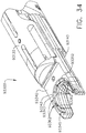
- FIG. 34 depicts a needle sensing system 93300 positioned within a suturing cartridge 93340.
- the suturing cartridge 93340 comprises a needle 93352 and a needle track 93342 configured to guide the needle 93352 through a needle firing stroke.
- the needle sensing system 93300 comprises a plurality of proximity sensors 93362 positioned within the needle track 93342.
- the sensors 93362 are molded into a sidewall 93343 of the needle track 93342.
- the sensors 93362 are molded into a top, or bottom, surface 93345 of the needle track 93342. Any suitable location within the end effector assembly can be used.
- the sensor information can be used to determine the location of the needle 93352 which can then be used to modify the operation of the surgical instrument if appropriate.
- a plurality of proximity sensors can be used within the end effector of a suturing device to determine if a needle of the suturing device has been de-tracked or fallen out of its track.
- an array of proximity sensors can be provided such that the needle contacts at least two sensors at all times during its firing stroke. If a control program determines that only one sensor is contacted based on the data from the proximity sensors, the control system can then determine that the needle has been de-tracked and modify the operation of the drive system accordingly.
- FIG. 35 depicts a needle sensing system 93400 positioned within a suturing cartridge 93440.
- the suturing cartridge 93440 comprises a needle 93452 and a needle track 93442 configured to guide the needle 93452 through a needle firing stroke.
- the needle sensing system 93400 comprises a plurality of conductive sensors 93462 positioned within the needle track 93442.
- the sensors 94362 are positioned adjacent a sidewall 93443 of the needle track 93442 such that the needle 93452 may progressively contact the sensors 94362 as the needle 93452 progresses through a needle firing stroke.
- the sensors 93462 are positioned adjacent a top, or bottom, surface 93445 of the needle track 93442. Any suitable location within the end effector assembly can be used.
- the sensor information can be used to determine the location of the needle 93452 which can then be used to modify the operation of the surgical instrument if appropriate.
- Another system for detecting and/or monitoring the location of the suturing needle during its firing stroke can include placing a circuit in communication with the needle track.
- a conductive supply leg can be wired in contact with one side of the needle track and a conductive return leg can be wired in contact with the other side of the needle track.
- the needle can act as a circuit switch and complete the circuit to lower the resistance within the circuit thereby providing a way to detect and/or monitor the location of the needle.
- Several of these circuits can be placed throughout the needle track. To aid the needle conductivity between the circuit contacts, brushes can be used to cradle the needle as the needle passes the circuit location.
- a flex circuit can also be used and can be adhered to inner walls of the needle track, for example.
- the flex circuit can contain multiple contacts, and/or terminals.
- the contacts can be molded directly into the walls.
- the contacts of the flex circuit can be folded over an inner wall of the needle track and stuck to the wall with an adhesive, for example, such that the contacts face the needle path.
- both of these mounting options can be employed.
- Another system for detecting and/or monitoring the location of the suturing needle during its firing stroke can include one or more inductive sensors. Such sensors can detect the needle and/or the needle grabber, or driver.
- Another system for detecting and/or monitoring the location of the suturing needle during its firing stroke can include using a light source and a photodetector which are positioned such that movement of the needle interrupts the detection of the light source by the photodetector.
- a light source can be positioned within, and/or near, the needle track, for example, and faced toward the needle path.
- the photodetector can be positioned opposite the light source such that needle can pass between the light source and the photodetector thereby interrupting the detection of light by the photodetector as the needle passes between the light source and the photodetector. Interruption of the light provided by the light source can indicate the needle's presence or lack thereof.
- the light source may be an infrared LED emitter, for example. Infrared light may be preferred due to its ability to penetrate tissue and organic debris, especially within a suturing site, which otherwise could produce a false positive reading by the photodetector. That said, any suitable light emitter could be used.
- FIG. 36 depicts a needle sensing system 93500 positioned within a suturing cartridge 93540.
- the suturing cartridge 93540 comprises a needle 93552 and a needle track 93542 configured to guide the needle 93552 through a needle firing stroke.
- the needle sensing system 93500 comprises a light source 93562 positioned at an entry point 93545 of the needle track 93542 and a photodetector 93564 positioned at an exit point 93543 of the needle track 93542.
- the light source 93562 is configured to emit light that spans across the capture opening of the suturing cartridge 93540 to indicate that the needle 93552 is in its home position.
- a control program can determine that the needle is not in its home position.
- the location of the needle 93552 can be determined by a control program based on the interruption of light between the light sources and photodetectors which can then be used to modify the operation of the surgical instrument if appropriate.
- FIG. 37 depicts a needle sensing system 93600 positioned within a suturing cartridge 93640.
- the suturing cartridge 93640 comprises a needle 93652 and a needle track 93642 configured to guide the needle 93652 through a needle firing stroke.
- the needle sensing system 93600 comprises a light source 93662 and a photodetector 93664 positioned at an exit point 93643 of the needle track 93642.
- the light source 93662 is configured to emit light that spans across the needle track cavity of the suturing cartridge 96640 to indicate the position of the needle 93652.
- another photodetector and light source are positioned at an exit point 93645 of the needle track 93642.
- an array of photodetectors and light sources are placed along the length of the needle track 93642.
- the location of the needle 93652 can be determined by a control program based on the interruption of light between the light source 93662 and the photodetector 93664.
- a surgical suturing needle can comprise a helical profile to provide helical suturing strokes.
- a needle comprises a length spanning 360 degrees where a butt end of the needle and a tip of the needle do not reside in the same plane and define a vertical distance therebetween.
- This needle can be actuated through a helical, or coil shaped, stroke to over-sew a staple line, for example, providing a three dimensional needle stroke.
- a needle having the helical shape discussed above provides a three dimensional suturing path.
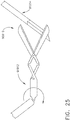
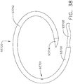
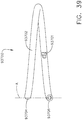
- FIGS. 38 and 39 depict a helical suturing needle assembly 93700 for use with a surgical suturing instrument.
- the suturing needle assembly 93700 comprises a tip 93704, a proximal end 93706, and a helical body portion 93702 extending therebetween.
- the helical body portion 93702 comprises a catch feature 93701 that a needle driver of a surgical suturing instrument is configured to catch on a return stroke of the driver.
- the tip 93704 and the proximal end 93706 reside in different horizontal planes and comprise a vertical distance therebetween; however, the tip 93704 and the proximal end 93706 terminate along a common axis A ( FIG. 39 ).
- the needle assembly 93700 can be actuated through a helical, or coil shaped, stroke to over-sew a staple line, for example, providing a three dimensional needle stroke.
- the needle comprises a circular configuration that is less than 360 degrees in circumference.
- the needle can be stored in the end effector in an orientation which stores the needle within the profile of the end effector. Once the end effector is positioned within the patient, the needle can be rotated out of its stored position to then perform a firing stroke.
- a surgical suturing instrument can accommodate different needle and suture sizes for different suturing procedures.
- Such an instrument can comprise a means for detecting the size of the needle and/or suture loaded into the instrument. This information can be communicated to the instrument so that the instrument can adjust the control program accordingly. Larger diameter needles may be rotated angularly at a slower rate than smaller diameter needles. Needles with different lengths may also be used with a single instrument.
- a surgical instrument can comprise means for detecting the length of the needle. This information can be communicated to a surgical instrument to modify the needle driver's path, for example. A longer needle may require a smaller stroke path from the needle driver to sufficiently advance the longer needle through its firing stroke as opposed to a smaller needle which may require a longer stroke path from the needle driver to sufficiently advance the shorter needle through its firing stroke in the same needle track.
- FIG. 40 depicts a logic diagram of a process 94100 depicting a control program for controlling a surgical instrument.
- the process 94100 comprises detecting 94101 the type of suturing cartridge installed within the surgical suturing instrument.
- different suture cartridges may have different suture lengths, needle lengths, needle diameters, and/or suture materials, for example.
- the type of suture cartridge and/or its characteristics can be communicated to a control circuit by an identification chip positioned within the cartridge such that, when a suture cartridge is installed within a surgical instrument, the control circuit can identify what type of cartridge has been installed and assess the characteristics of the suture cartridge.
- a control circuit may adjust the control motions that will be applied to the suture cartridge.
- firing speeds may differ for different sized needles.
- Another example may include adjusting the range of angular needle rotation based on different needle lengths, or sizes.
- the process 94100 implemented by a process comprises adjusting 94103 a motor control program of the instrument based on what type of suture cartridge is installed.
- a suture needle is stored in a suturing instrument in a folded manner.
- the suture needle comprises two portions which are hingedly connected to one another at a hinge. After the end effector has been passed through the trocar, the suture needle can be unfolded and locked into its unfolded configuration.
- a one-way snap feature can be used to rigidly hold the suture needle in its unfolded configuration.
- a surgical instrument is configured to apply a suture to the tissue of a patient which comprises a lockout system.
- the lockout system comprises a locked configuration and an unlocked configuration.
- the surgical instrument further comprises a control circuit and is configured to identify if a cartridge is installed or not installed within an end effector of the surgical instrument.
- the control circuit is configured to place the lockout system in the locked condition when a cartridge is not installed in the end effector and place the lockout system in the unlocked condition when a cartridge is installed in the end effector.
- a lockout system can include an electrical sensing circuit of which a cartridge can complete upon installation indicating that a cartridge has been installed.
- the actuator comprises an electric motor and the lockout system can prevent power from being supplied to the electric motor.
- the actuator comprises a mechanical trigger
- the lockout system blocks the mechanical trigger from being pulled to actuate the suture needle.
- the lockout system prevents an actuator from being actuated.
- the lockout system permits the actuator to deploy the suture positioned within the cartridge.
- the control circuit provides haptic feedback to a user of the surgical instrument when the electrical sensing circuit places the surgical instrument in the locked configuration.
- the control circuit prevents the actuation of an electric motor configured to actuate the actuator when the electrical sensing circuit determines that the lockout system is in the locked configuration.
- the lockout system is in the unlocked configuration when a cartridge is positioned in the end effector and the cartridge has not been completely expended.
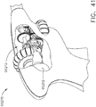
- FIGS. 41 and 42 depict a handle assembly 95200 that is operable for use a surgical suturing instrument.
- the handle assembly 95200 is connected to a proximal end of a shaft.
- the handle assembly 95200 includes a motor 95202 and a transmission assembly 95210.
- the motor 95202 is configured to actuate a needle of a surgical suturing end effector by way of a needle driver, articulate the end effector, and rotate the end effector by way of the transmission assembly 95210.
- the transmission assembly 95210 is shifted between three states by a double acting solenoid, for example, so as to allow the motor 95202 to be used to actuate a needle of a surgical suturing end effector, articulate the end effector, and/or rotate the end effector.
- the handle assembly 95200 could take the form of a robotic interface or a housing comprising gears, pulleys, and/or servomechanisms, for example. Such an arrangement could be used with a robotic surgical system.
- FIG. 43 depicts a suturing cartridge 93590 comprising a lower body 93581, an upper body 93582, and a needle cover 93583.
- the cartridge 93590 further comprises a drive system comprising a needle driver 93586, a rotary input 93594, and a link 93585 connecting the needle driver 93586 and the rotary input 93594.
- the needle driver 93586, rotary input 93594, and link 93585 are captured between the lower body 93581 and the upper body 93582.
- the needle driver 93586, the link 93585, and the rotary input 93594 are configured to be actuated to drive a needle 93570 through a needle firing stroke by way of a motor-driven system, a manually-driven handheld system, and/or a robotic system, for example.
- the lower and upper bodies 93581, 93582 are attached to one another using any suitable technique, such as, for example, welds, pins, adhesives, and/or the like to form the cartridge body.
- the needle 93570 comprises a leading end 93571 configured to puncture tissue, a trailing end 93572, and a length of suture 93573 extending from and attached to the trailing end 93572.
- the needle 93570 is configured to rotate in a circular path defined by a needle track 93584.
- the needle track 93584 is defined in the cartridge body.
- the needle 93570 is configured to exit one of a first arm 95393A and a second arm 95393B of the cartridge body and enter the other of the first arm 95393A and the second arm 95393B during a needle firing stroke.
- Recessed features 93574 are provided to so that the needle driver 93586 can engage and drive the needle 93570 through the needle firing stroke in a ratchet-like motion.
- the needle 93570 is positioned between the needle track 93584 and the needle cover 93583.
- the suturing cartridge 93590 further comprises a cage 93587 that is configured to slide over the cartridge body to attach the needle cover 93583 to the lower body 93581.
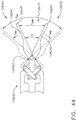
- a surgical system 128000 is illustrated in FIG. 44 .
- the surgical system 128000 comprises a handle, a shaft 128020 extending from the handle, and an end effector 128030 extending from the shaft 128020.
- the surgical system 128000 comprises a housing configured to be mounted to a robotic surgical system.
- the shaft 128020 extends from the robotic housing mount instead of the handle.
- the end effector 128030 comprises jaws 128040 and 128050 which are closeable to grasp a target, such as the tissue T of a patient and/or a suture needle, for example, as discussed in greater detail below.
- the jaws 128040 and 128050 are also openable to dissect the tissue of a patient, for example.
- the jaws 128040 and 128050 are insertable into the patient tissue to create an otomy therein and then spread to open the otomy, as discussed in greater detail below.
- the jaws 128040 and 128050 are pivotably coupled to the shaft 128020 about a pivot joint 128060.
- the pivot joint 128060 defines a fixed axis of rotation, although any suitable arrangement could be used.
- the jaw 128040 comprises a distal end, or tip, 128041 and an elongate profile which narrows from its proximal end to its distal end 128041.
- the jaw 128050 comprises a distal end, or tip, 128051 and an elongate profile which narrows from its proximal end to its distal end 128051.
- the distance between the tips 128041 and 128051 define the mouth width, or opening, 128032 of the end effector 128030.
- the mouth 128032 When the tips 128041 and 128051 are close to one another, or in contact with one another, the mouth 128032 is small, or closed, and the mouth angle e is small, or zero. When the tips 128041 and 128051 are far apart, the mouth 128032 is large and the mouth angle e is large.
- the jaws of the end effector 128030 are driven by a jaw drive system including an electric motor.
- a voltage potential is applied to the electric motor to rotate the drive shaft of the electric motor and drive the jaw drive system.
- the surgical system 128000 comprises a motor control system configured to apply the voltage potential to the electric motor.
- the motor control system is configured to apply a constant DC voltage potential to the electric motor.
- the electric motor will run at a constant speed, or an at least substantially constant speed.
- the motor control system comprises a pulse width modulation (PWM) circuit and/or a frequency modulation (FM) circuit which can apply voltage pulses to the electric motor.
- PWM and/or FM circuits can control the speed of the electric motor by controlling the frequency of the voltage pulses supplied to the electric motor, the duration of the voltage pulses supplied to the electric motor, and/or the duration between the voltage pulses supplied to the electric motor.
- the motor control system is also configured to monitor the current drawn by the electric motor as a means for monitoring the force being applied by the jaws of the end effector 128030.
- the loading force on the jaws is low.
- the loading force on the jaws is high when the current being drawn by the electric motor is high.
- the voltage being applied to the electric motor is fixed, or held constant, and the motor current is permitted to fluctuate as a function of the force loading at the jaws.
- the motor control system is configured to limit the current drawn by the electric motor to limit the force that can be applied by the jaws.
- the motor control system can include a current regulation circuit that holds constant, or at least substantially constant, the current drawn by the electric motor to maintain a constant loading force at the jaws.
- the force generated between the jaws of the end effector 128030, and/or on the jaws of the end effector 128030, may be different depending on the task that the jaws are being used to perform. For instance, the force needed to hold a suture needle may be high as suture needles are typically small and it is possible that a suture needle may slip during use. As such, the jaws of the end effector 128030 are often used to generate large forces when the jaws are close together. On the other hand, the jaws of the end effector 128030 are often used to apply smaller forces when the jaws are positioned further apart to perform larger, or gross, tissue manipulation, for example.
- the loading force, f, experienced by the jaws of the end effector 128030 can be limited by a force profile stored in the motor control system.
- the force limit profile 128110o for opening the jaws 128040 and 128050 is different than the force limit profile 128110c for closing the jaws 128040 and 128050. This is because the procedures performed when forcing the jaws 128040 and 128050 open are typically different than the procedures performed when forcing the jaws 128040 and 128050 closed. That said, the opening and closing force limit profiles could be the same.
- the force limit profiles typically come into play when the jaws 128040 and 128050 are being used to perform a particular procedure within the patient. For instance, the jaws 128040 and 128050 are forced open to create and expand an otomy in the tissue of a patient, as represented by graph sections 128115 and 128116, respectively, of graph 128100, while the jaws 128040 and 128050 are forced closed to grasp a needle and/or the patient tissue, as represented by graph sections 128111 and 128112, respectively, of graph 128100.
- the opening and closing jaw force limit profiles 1281100 and 128110c are depicted on the opposite sides of a zero force line depicted in the graph 128100.
- the jaw force limit threshold is higher - for both force limit profiles 128110o and 128110c - when the jaws 128040 and 128050 are just being opened from their fully-closed position.
- the jaw force limit threshold is lower-for both force limit profiles 128110o and 128110c - when the jaws 128040 and 128050 are reaching their fully-opened position.
- the force that the jaws 128040 and 128050 are allowed to apply is a function of the mouth opening size between the jaws and/or the direction in which the jaws are being moved.
- the jaw force f limit is very low as compared to when the jaws 128040 and 128050 are more closed to perform gross tissue manipulation, referring to graph section 128113 of upper graph section 128110.
- different jaw force limit profiles can be used for different jaw configurations. For instance, Maryland dissectors, which have narrow and pointy jaws, may have a different jaw force limit profile than a grasper having blunt jaws, for example.
- the speed of the jaws 128040 and 128050 can be controlled and/or limited by the motor control system as a function of the mouth opening size between the jaws 128040 and 128050 and/or the direction the jaws are being moved.
- the rate limit profile for moving the jaws 128040 and 128050 permits the jaws to be moved slowly when the jaws are near their closed position and moved quickly when the jaws are near their open position. In such instances, the jaws 128040 and 128050 are accelerated as the jaws are opened.
- Such an arrangement can provide fine control over the jaws 128040 and 128050 when they are close together to facilitate the fine dissection of tissue, for example.
- the rate limit profile for opening and closing the jaws 128040 and 128050 is the same, but they could be different in other embodiments.
- the rate limit profile for moving the jaws 128040 and 128050 permits the jaws to be moved quickly when the jaws are near their closed position and slowly when the jaws are near their open position. In such instances, the jaws 128040 and 128050 are decelerated as the jaws are opened.
- Such an arrangement can provide fine control over the jaws 128040 and 128050 when the jaws are being used to stretch an otomy, for example.
- the speed of the jaws 128040 and 128050 can be adjusted once the jaws experience loading resistance from the patient tissue, for example.
- the jaw opening rate and/or the jaw closing rate can be reduced once the jaws 128040 and 128050 begin to experience force resistance above a threshold, for example.
- the handle of the surgical system 128000 comprises an actuator, the motion of which tracks, or is supposed to track, the motion of the jaws 128040 and 128050 of the end effector 128030.
- the actuator can comprise a scissors-grip configuration which is openable and closable to mimic the opening and closing of the end effector jaws 128040 and 128050.
- the control system of the surgical system 128000 can comprise one or more sensor systems configured to monitor the state of the end effector jaws 128040 and 128050 and the state of the handle actuator and, if there is a discrepancy between the two states, the control system can take a corrective action once the discrepancy exceeds a threshold and/or threshold range.
- control system can provide feedback, such as audio, tactile, and/or haptic feedback, for example, to the clinician that the discrepancy exists and/or provide the degree of discrepancy to the clinician. In such instances, the clinician can make mental compensations for this discrepancy.
- control system can adapt its control program of the jaws 128040 and 128050 to match the motion of the actuator. In at least one instance, the control system can monitor the loading force being applied to the jaws and align the closed position of the actuator with the position of the jaws when the jaws experience the peak force loading condition when grasping tissue.
- control system can align the open position of the actuator with the position of the jaws when the jaws experience the minimum force loading condition when grasping tissue.
- control system is configured to provide the clinician with a control to override these adjustments and allow the clinician to use their own discretion in using the surgical system 128000 in an appropriate manner.
- a surgical system 128700 is illustrated in FIGS. 46 and 47 .
- the surgical system 128700 comprises a handle, a shaft assembly 128720 extending from the handle, and an end effector 128730 extending from the shaft assembly 128720.
- the surgical system 128700 comprises a housing configured to be mounted to a robotic surgical system.
- the shaft 128720 extends from the robotic housing mount instead of the handle.
- the end effector 128730 comprises shears configured to transect the tissue of a patient.
- the shears comprise two jaws 128740 and 128750 configured to transect the patient tissue positioned between the jaws 128740 and 128750 as the jaws 128740 and 128750 are being closed.
- Each of the jaws 128740 and 128750 comprises a sharp edge configured to cut the tissue and are pivotably mounted to the shaft 128720 about a pivot joint 128760.
- Such an arrangement can comprise bypassing scissors shears.
- one of the jaws 128740 and 128750 comprises a knife edge and the other comprises a mandrel against the tissue is supported and transected.
- Such an arrangement can comprise a knife wedge in which the knife wedge is moved toward the mandrel.
- the jaw comprising the knife edge is movable and the jaw comprising the mandrel is stationary.
- the tissue-engaging edges of one or both of the jaws 128740 and 128750 are not necessarily sharp.
- the end effector 128730 comprises two scissor jaws 128740 and 128750 movable between an open position and a closed position to cut the tissue of a patient.
- the jaw 128740 comprises a sharp distal end 128741 and the jaw 128750 comprises a sharp distal end 128751 which are configured to snip the tissue of the patient at the mouth 128731 of the end effector 128730, for example. That said, other embodiments are envisioned in which the distal ends 128741 and 128751 are blunt and can be used to dissect tissue, for example.
- the jaws are driven by a jaw drive system including an electric drive motor, the speed of which is adjustable to adjust the closure rate and/or opening rate of the jaws.
- the control system of the surgical system is configured to monitor the loading, or shear, force on the jaws 128740 and 128750 as the jaws 128740 and 128750 are being closed and adaptively slow down the drive motor when large forces, or forces above a threshold Fc, are experienced by the jaws 128740 and 128750. Such large forces often occur when the tissue T being cut by the jaws 128740 and 128750 is thick, for example. Similar to the above, the control system can monitor the current drawn by the drive motor as a proxy for the loading force being experienced by the jaws 128740 and 128750.
- control system can be configured to measure the jaw loading force directly by one or more load cells and/or strain gauges, for example. Once the loading force experienced by the jaws 128740 and 128750 drops below the force threshold Fc, the control system can adaptively speed up the jaw closure rate. Alternatively, the control system can maintain the lower closure rate of the jaws 128740 and 128750 even though the force threshold is no longer being exceeded.
- the surgical system 128700 can provide mechanical energy or a mechanical cutting force to the tissue of a patient. That said, the surgical system 128700 is also configured to provide electrosurgical energy or an electrosurgical cutting force to the tissue of a patient.
- the electrosurgical energy comprises RF energy, for example; however, electrosurgical energy could be supplied to the patient tissue at any suitable frequency.
- the surgical system 128700 can be configured to supply DC power to the patient tissue.
- the surgical system 128700 comprises a generator in electrical communication with one or more electrical pathways defined in the instrument shaft 128720 which can supply electrical power to the jaws 128740 and 128750 and also provide a return path for the current.
- the jaw 128740 comprises an electrode 128742 in electrical communication with a first electrical pathway in the shaft 128720 and the jaw 128750 comprises an electrode 128752 in electrical communication with a second electrical pathway in the shaft 128720.
- the first and second electrical pathways are electrically insulated, or at least substantially insulated, from one another and the surrounding shaft structure such that the first and second electrical pathways, the electrodes 128742 and 128752, and the tissue positioned between the electrodes 128742 and 128752 forms a circuit.
- Such an arrangement provides a bipolar arrangement between the electrodes 128742 and 128752. That said, embodiments are envisioned in which a monopolar arrangement could be used. In such an arrangement, the return path for the current goes through the patient and into a return electrode positioned on or under the patient, for example.
- the tissue of a patient can be cut by using a mechanical force and/or an electrical force.
- mechanical and electrical forces can be applied simultaneously and/or sequentially. For instance, both forces can be applied at the beginning of a tissue cutting actuation and then the mechanical force can be discontinued in favor of the electrosurgical force finishing the tissue cutting actuation.
- Such an approach can apply an energy-created hemostatic seal to the tissue after the mechanical cutting has been completed.
- the electrosurgical force is applied throughout the duration of the tissue cutting actuation.
- the mechanical cutting force without the electrosurgical cutting force, can be used to start a tissue cutting actuation which is then followed by the electrosurgical cutting force after the mechanical cutting force has been stopped.
- the mechanical and electrosurgical forces are not overlapping or co-extensive.
- both the mechanical and electrosurgical forces are overlapping and co-extensive throughout the entire tissue cutting actuation.
- both forces are overlapping and co-extensive throughout the entire tissue cutting actuation but in magnitudes or intensities that change during the tissue cutting actuation.
- any suitable combination, pattern, and/or sequence of mechanical and electrosurgical cutting forces and energies could be used.
- the surgical system 128700 comprises a control system configured to co-ordinate the application of the mechanical force and electrosurgical energy to the patient tissue.
- the control system is in communication with the motor controller which drives the jaws 128740 and 128750 and, also, the electrical generator and comprises one or more sensing systems for monitoring the mechanical force and electrosurgical energy being applied to the tissue.
- Systems for monitoring the forces within a mechanical drive system are disclosed elsewhere herein.
- Systems for monitoring the electrosurgical energy being applied to the patient tissue include monitoring the impedance, or changes in the impedance, of the patient tissue via the electrical pathways of the electrosurgical circuit. In at least one instance, referring to the graph 128800 in FIG.
- the RF current/voltage ratio of the electrosurgical power being applied to the patient tissue by the generator is evaluated by monitoring the current and voltage of the power being supplied by the generator.
- the impedance of the tissue and the RF current/voltage ratio of the electrosurgical power are a function of many variables such as the temperature of the tissue, the density of the tissue, the thickness of the tissue, the type of tissue between the jaws 128740 and 128750, the duration in which the power is applied to the tissue, among others, which change throughout the application of the electrosurgical energy.
- control system and/or generator of the surgical system 128700 comprises one or more ammeter circuits and/or voltmeter circuits configured to monitor the electrosurgical current and/or voltage, respectively, being applied to the patient tissue.
- a minimum amplitude limit and/or a maximum amplitude limit on the current being applied to the patient tissue can be preset in the control system and/or can be controllable by the user of the surgical instrument system through one or more input controls.
- the minimum and maximum amplitude limits can define a current envelope within which the electrosurgical portion of the surgical system 128700 is operated.
- control system of the surgical system 128700 is configured to adaptively increase the electrosurgical energy applied to the patient tissue when the drive motor slows.
- the motor slowing can be a reaction to an increase in the tissue cutting load and/or an adaptation of the control system.
- control system of the surgical system 128700 is configured to adaptively increase the electrosurgical energy applied to the patient tissue when the drive motor stops.
- the motor stopping can be a reaction to an increase in the tissue cutting load and/or an adaptation of the control system.
- Increasing the electrosurgical energy when the electric motor slows and/or stops can compensate for a reduction in mechanical cutting energy.
- the electrosurgical energy can be reduced and/or stopped when the electric motor slows and/or stops. Such embodiments can afford the clinician to evaluate the situation in a low-energy environment.
- control system of the surgical system 128700 is configured to adaptively decrease the electrosurgical energy applied to the patient tissue when the drive motor speeds up.
- the motor speeding up can be a reaction to a decrease in the cutting load and/or an adaptation of the control system. Decreasing the electrosurgical energy when the electric motor slows and/or stops can compensate for, or balance out, an increase in mechanical cutting energy.
- the electrosurgical energy can be increased when the electric motor speeds up. Such embodiments can accelerate the closure of the jaws and provide a clean, quick cutting motion.
- control system of the surgical system 128700 is configured to adaptively increase the speed of the drive motor when the electrosurgical energy applied to the patient tissue decreases.
- the electrosurgical energy decreasing can be a reaction to a change in tissue properties and/or an adaptation of the control system.
- control system of the surgical system 128700 is configured to adaptively increase the speed of the drive motor when electrosurgical energy applied to the patient tissue stops in response to an adaptation of the control system. Increasing the speed of the drive motor when the electrosurgical energy decreases or is stopped can compensate for a reduction in electrosurgical cutting energy.
- the speed of the drive motor can be reduced and/or stopped when the electrosurgical energy decreases and/or is stopped. Such embodiments can afford the clinician to evaluate the situation in a low-energy and/or static environment.
- control system of the surgical system 128700 is configured to adaptively decrease the speed of the electric motor when the electrosurgical energy applied to the patient tissue increases.
- the electrosurgical energy increasing can be a reaction to a change in tissue properties and/or an adaptation of the control system. Decreasing the drive motor speed when the electrosurgical energy increases can compensate for, or balance out, an increase in electrosurgical cutting energy.
- the drive motor speed can be increased when the electrosurgical energy increases. Such embodiments can accelerate the closure of the jaws and provide a clean, quick cutting motion.
- the surgical system 128700 comprises controls, such as on the handle of the surgical system 128700, for example, that a clinician can use to control when the mechanical and/or electrosurgical forces are applied.
- the control system of the surgical system 128700 is configured to monitor the mechanical force and electrical energy being applied to the tissue and adjust one or the other, if needed, to cut the tissue in a desirable manner according to one or more predetermined force-energy curves and/or matrices.
- the control system can increase the electrical energy being delivered to the tissue once the mechanical force being applied reaches a threshold limit.
- the control system is configured to consider other parameters, such as the impedance of the tissue being cut, when making adjustments to the mechanical force and/or electrical energy being applied to the tissue.
- FIG. 50 is a logic diagram of a control system 75000 for use with any of the various suturing instruments described herein.
- the control system 75000 comprises a control circuit.
- the control circuit includes a microcontroller 75040 comprising a processor 75020 and a memory 75030.
- One or more sensors such as sensor 75080, sensor 75090, sensor 71502, and sensor array 71940, for example, provide real time feedback to the processor 75020.
- the control system 75000 further comprises a motor driver 75050 configured to control an electric motor 75010 and a tracking system 75060 configured to determine the position of one or more movable components in the suturing instruments, such as a needle, needle drive system, suture, and/or suture spool, for example.
- the tracking system 75060 provides position information to the processor 75020, which can be programmed or configured to, among other things, determine the position of the suture needle, for example.
- the motor driver 75050 may be an A3941 available from Allegro Microsystems, Inc., for example; however, other motor drivers may be readily substituted for use in the tracking system 75060.
- a detailed description of an absolute positioning system is described in U.S. Patent Application Publication No. 2017/0296213 , entitled SYSTEMS AND METHODS FOR CONTROLLING A SURGICAL STAPLING AND CUTTING INSTRUMENT, the entire disclosure of which is hereby incorporated herein by reference.
- the microcontroller 75040 may be any single core or multicore processor such as those known under the trade name ARM Cortex by Texas Instruments, for example.
- the microcontroller 75040 is a LM4F230H5QR ARM Cortex-M4F Processor Core, available from Texas Instruments, for example, comprising on-chip memory of 256 KB single-cycle flash memory, or other non-volatile memory, up to 40 MHz, a prefetch buffer to improve performance above 40 MHz, a 32 KB single-cycle serial random access memory (SRAM), internal read-only memory (ROM) loaded with StellarisWare® software, 2 KB electrically erasable programmable read-only memory (EEPROM), one or more pulse width modulation (PWM) modules and/or frequency modulation (FM) modules, one or more quadrature encoder inputs (QEI) analog, one or more 12-bit Analog-to-Digital Converters (ADC) with 12 analog input channels, for example, details of which are available from the
- the microcontroller 75040 comprises a safety controller comprising two controller-based families such as TMS570 and RM4x known under the trade name Hercules ARM Cortex R4, also by Texas Instruments.
- the safety controller may be configured specifically for IEC 61508 and ISO 26262 safety critical applications, among others, to provide advanced integrated safety features while delivering scalable performance, connectivity, and memory options.
- the microcontroller 75040 is programmed to perform various functions such as precisely controlling the speed and/or position of the suture needle, for example.
- the microcontroller 75040 is also programmed to precisely control the rotational speed and position of the end effector of the suturing instrument and the articulation speed and position of the end effector of the suturing instrument.
- the microcontroller 75040 computes a response in the software of the microcontroller 75040.
- the computed response is compared to a measured response of the actual system to obtain an "observed" response, which is used for actual feedback decisions.
- the observed response is a favorable, tuned, value that balances the smooth, continuous nature of the simulated response with the measured response, which can detect outside influences on the system.
- the motor 75010 is controlled by the motor driver 75050.
- the motor 75010 is a DC brushed driving motor having a maximum rotational speed of approximately 25,000 RPM, for example.
- the motor 75010 includes a brushless motor, a cordless motor, a synchronous motor, a stepper motor, or any other suitable electric motor.
- the motor driver 75050 may comprise an H-bridge driver comprising field-effect transistors (FETs), for example.
- FETs field-effect transistors
- the motor driver 75050 may be an A3941 available from Allegro Microsystems, Inc., for example.
- the A3941 motor driver 75050 is a full-bridge controller for use with external N-channel power metal oxide semiconductor field effect transistors (MOSFETs) specifically designed for inductive loads, such as brush DC motors.
- the motor driver 75050 comprises a unique charge pump regulator provides full (>10 V) gate drive for battery voltages down to 7 V and allows the A3941 motor driver 75050 to operate with a reduced gate drive, down to 5.5 V.
- a bootstrap capacitor may be employed to provide the above-battery supply voltage required for N-channel MOSFETs.
- An internal charge pump for the high-side drive allows DC (100% duty cycle) operation.
- the full bridge can be driven in fast or slow decay modes using diode or synchronous rectification.
- current recirculation can be through the high-side or the lowside FETs.
- the power FETs are protected from shoot-through by resistor adjustable dead time.
- Integrated diagnostics provide indication of undervoltage, overtemperature, and power bridge faults, and can be configured to protect the power MOSFETs under most short circuit conditions. Other motor drivers may be readily substituted.
- the tracking system 75060 comprises a controlled motor drive circuit arrangement comprising one or more position sensors, such as the sensor 75080, sensor 75090, sensor 71502, and sensory array 71940, for example.
- the position sensors for an absolute positioning system provide a unique position signal corresponding to the location of a displacement member.
- the term displacement member is used generically to refer to any movable member of any of the surgical instruments disclosed herein.
- the displacement member may be coupled to any position sensor suitable for measuring linear displacement or rotational displacement.
- Linear displacement sensors may include contact or non-contact displacement sensors.
- the displacement sensors may comprise linear variable differential transformers (LVDT), differential variable reluctance transducers (DVRT), a slide potentiometer, a magnetic sensing system comprising a movable magnet and a series of linearly arranged Hall Effect sensors, a magnetic sensing system comprising a fixed magnet and a series of movable linearly arranged Hall Effect sensors, an optical sensing system comprising a movable light source and a series of linearly arranged photo diodes or photo detectors, or an optical sensing system comprising a fixed light source and a series of movable linearly arranged photo diodes or photo detectors, or any combination thereof.
- LVDT linear variable differential transformers
- DVRT differential variable reluctance transducers
- a slide potentiometer a magnetic sensing system comprising a movable magnet and a series of linearly arranged Hall Effect sensors
- a magnetic sensing system comprising a fixed magnet and a series of movable linearly arranged Hall Effect sensors
- the position sensors 75080, 75090, 71502, and 71940 may comprise any number of magnetic sensing elements, such as, for example, magnetic sensors classified according to whether they measure the total magnetic field or the vector components of the magnetic field.
- the techniques used to produce both types of magnetic sensors encompass many aspects of physics and electronics.
- the technologies used for magnetic field sensing include search coil, fluxgate, optically pumped, nuclear precession, SQUID, Hall-Effect, anisotropic magnetoresistance, giant magnetoresistance, magnetic tunnel junctions, giant magnetoimpedance, magnetostrictive/piezoelectric composites, magnetodiode, magnetotransistor, fiber optic, magnetooptic, and microelectromechanical systems-based magnetic sensors, among others.
- one or more of the position sensors of the tracking system 75060 comprise a magnetic rotary absolute positioning system.
- Such position sensors may be implemented as an AS5055EQFT single-chip magnetic rotary position sensor available from Austria Microsystems, AG and can be interfaced with the controller 75040 to provide an absolute positioning system.
- a position sensor comprises a low-voltage and low-power component and includes four Hall-Effect elements in an area of the position sensor that is located adjacent a magnet.
- a high resolution ADC and a smart power management controller are also provided on the chip.
- a CORDIC processor for Coordinate Rotation Digital Computer, also known as the digit-by-digit method and Volder's algorithm, is provided to implement a simple and efficient algorithm to calculate hyperbolic and trigonometric functions that require only addition, subtraction, bitshift, and table lookup operations.
- the angle position, alarm bits, and magnetic field information are transmitted over a standard serial communication interface such as an SPI interface to the controller 75040.
- the position sensors can provide 12 or 14 bits of resolution, for example.
- the position sensors can be an AS5055 chip provided in a small QFN 16-pin 4x4x0.85mm package, for example.
- the tracking system 75060 may comprise and/or be programmed to implement a feedback controller, such as a PID, state feedback, and adaptive controller.
- a power source converts the signal from the feedback controller into a physical input to the system, in this case voltage.
- Other examples include pulse width modulation (PWM) and/or frequency modulation (FM) of the voltage, current, and force.
- PWM pulse width modulation
- FM frequency modulation
- Other sensor(s) may be provided to measure physical parameters of the physical system in addition to position.
- the other sensor(s) can include sensor arrangements such as those described in U.S. Patent No. 9,345,481 , entitled STAPLE CARTRIDGE TISSUE THICKNESS SENSOR SYSTEM, which is hereby incorporated herein by reference in its entirety; U.S. Patent Application Publication No.
- the absolute positioning system may comprise a compare and combine circuit to combine a computed response with a measured response using algorithms such as weighted average and theoretical control loop that drives the computed response towards the measured response.
- the computed response of the physical system takes into account properties like mass, inertial, viscous friction, inductance resistance, etc., to predict what the states and outputs of the physical system will be by knowing the input.
- the absolute positioning system provides an absolute position of the displacement member upon power up of the instrument without retracting or advancing the displacement member to a reset (zero or home) position as may be required with conventional rotary encoders that merely count the number of steps forwards or backwards that the motor 75010 has taken to infer the position of a device actuator, the needle driver, and the like.
- a sensor 75080 and/or 71502 comprising a strain gauge or a micro-strain gauge, for example, is configured to measure one or more parameters of the end effector of the suturing instrument, such as, for example, the strain experienced by the needle during a suturing operation. The measured strain is converted to a digital signal and provided to the processor 75020.
- a sensor 75090 comprising a load sensor, for example, can measure another force applied by the suturing instrument.
- a current sensor 75070 can be employed to measure the current drawn by the motor 75010. The force required to throw, or rotate, the suturing needle can correspond to the current drawn by the motor 75010, for example. The measured force is converted to a digital signal and provided to the processor 75020.
- a magnetic field sensor can be employed to measure the thickness of the captured tissue. The measurement of the magnetic field sensor can also be converted to a digital signal and provided to the processor 75020.
- the measurements of the tissue thickness and/or the force required to rotate the needle through tissue as measured by the sensors can be used by the controller 75040 to characterize the position and/or speed of the movable member being tracked.
- the memory 75030 may store a technique, an equation, and/or a look-up table which can be employed by the controller 75040 in the assessment.
- the controller 75040 can provide the user of the suturing instrument with a choice as to the manner in which the suturing instrument should be operated.
- a display 75044 can display a variety of operating conditions of the suturing instrument and can include touch screen functionality for data input.
- information displayed on the display 75044 may be overlaid with images acquired via the imaging modules of one or more endoscopes and/or one or more additional surgical instruments used during the surgical procedure.
- the suturing instruments disclosed herein may comprise control systems.
- Each of the control systems can comprise a circuit board having one or more processors and/or memory devices.
- the control systems are configured to store sensor data, for example. They are also configured to store data which identifies the type of suturing instrument attached to a handle or housing. More specifically, the type of suturing instrument can be identified when attached to the handle or housing by the sensors and the sensor data can be stored in the control system. Moreover, they are also configured to store data including whether or not the suturing instrument has been previously used and/or how many times the suture needle has been cycled. This information can be obtained by the control system to assess whether or not the suturing instrument is suitable for use and/or has been used less than a predetermined number of times, for example.
- the surgical instrument systems described herein are motivated by an electric motor; however, the surgical instrument systems described herein can be motivated in any suitable manner.
- the motors disclosed herein may comprise a portion or portions of a robotically controlled system.
- U.S. Patent Application Serial No. 13/118,241 entitled SURGICAL STAPLING INSTRUMENTS WITH ROTATABLE STAPLE DEPLOYMENT ARRANGEMENTS, now U.S. Patent No. 9,072,535 , for example, discloses several examples of a robotic surgical instrument system in greater detail, the entire disclosure of which is incorporated by reference herein.
- an end effector in accordance with various embodiments can comprise electrodes configured to heat and seal the tissue.
- an end effector in accordance with certain embodiments can apply vibrational energy to seal the tissue.
- various embodiments are envisioned which utilize a suitable cutting means to cut the tissue.
- the devices disclosed herein can be designed to be disposed of after a single use, or they can be designed to be used multiple times. In either case, however, a device can be reconditioned for reuse after at least one use. Reconditioning can include any combination of the steps including, but not limited to, the disassembly of the device, followed by cleaning or replacement of particular pieces of the device, and subsequent reassembly of the device. In particular, a reconditioning facility and/or surgical team can disassemble a device and, after cleaning and/or replacing particular parts of the device, the device can be reassembled for subsequent use.
- reconditioning of a device can utilize a variety of techniques for disassembly, cleaning/replacement, and reassembly. Use of such techniques, and the resulting reconditioned device, are all within the scope of the present application.
- the devices disclosed herein may be processed before surgery.
- a new or used instrument may be obtained and, when necessary, cleaned.
- the instrument may then be sterilized.
- the instrument is placed in a closed and sealed container, such as a plastic or TYVEK bag.
- the container and instrument may then be placed in a field of radiation that can penetrate the container, such as gamma radiation, x-rays, and/or high-energy electrons.
- the radiation may kill bacteria on the instrument and in the container.
- the sterilized instrument may then be stored in the sterile container.
- the sealed container may keep the instrument sterile until it is opened in a medical facility.
- a device may also be sterilized using any other technique known in the art, including but not limited to beta radiation, gamma radiation, ethylene oxide, plasma peroxide, and/or steam.
Applications Claiming Priority (37)
| Application Number | Priority Date | Filing Date | Title |
|---|---|---|---|
| US201762578855P | 2017-10-30 | 2017-10-30 | |
| US201762578835P | 2017-10-30 | 2017-10-30 | |
| US201762578844P | 2017-10-30 | 2017-10-30 | |
| US201762578804P | 2017-10-30 | 2017-10-30 | |
| US201762578817P | 2017-10-30 | 2017-10-30 | |
| US201762578793P | 2017-10-30 | 2017-10-30 | |
| US201762611341P | 2017-12-28 | 2017-12-28 | |
| US201762611340P | 2017-12-28 | 2017-12-28 | |
| US201762611339P | 2017-12-28 | 2017-12-28 | |
| US15/908,021 US10736616B2 (en) | 2017-10-30 | 2018-02-28 | Surgical instrument with remote release |
| US15/908,040 US10952708B2 (en) | 2017-10-30 | 2018-02-28 | Surgical instrument with rotary drive selectively actuating multiple end effector functions |
| US15/908,057 US11129634B2 (en) | 2017-10-30 | 2018-02-28 | Surgical instrument with rotary drive selectively actuating multiple end effector functions |
| US15/908,143 US10932804B2 (en) | 2017-10-30 | 2018-02-28 | Surgical instrument with sensor and/or control systems |
| US15/908,058 US11116485B2 (en) | 2017-10-30 | 2018-02-28 | Surgical instrument with modular power sources |
| US15/908,012 US10842473B2 (en) | 2017-10-30 | 2018-02-28 | Surgical instrument having dual rotatable members to effect different types of end effector movement |
| US201862649300P | 2018-03-28 | 2018-03-28 | |
| US201862649309P | 2018-03-28 | 2018-03-28 | |
| US201862649291P | 2018-03-28 | 2018-03-28 | |
| US201862649296P | 2018-03-28 | 2018-03-28 | |
| US201862649307P | 2018-03-28 | 2018-03-28 | |
| US201862649294P | 2018-03-28 | 2018-03-28 | |
| US201862649333P | 2018-03-28 | 2018-03-28 | |
| US201862649313P | 2018-03-28 | 2018-03-28 | |
| US201862649320P | 2018-03-28 | 2018-03-28 | |
| US201862649302P | 2018-03-28 | 2018-03-28 | |
| US201862649310P | 2018-03-28 | 2018-03-28 | |
| US201862649327P | 2018-03-28 | 2018-03-28 | |
| US201862649323P | 2018-03-28 | 2018-03-28 | |
| US201862649315P | 2018-03-28 | 2018-03-28 | |
| US201862659900P | 2018-04-19 | 2018-04-19 | |
| US201862665129P | 2018-05-01 | 2018-05-01 | |
| US201862665128P | 2018-05-01 | 2018-05-01 | |
| US201862665134P | 2018-05-01 | 2018-05-01 | |
| US201862665139P | 2018-05-01 | 2018-05-01 | |
| US201862665192P | 2018-05-01 | 2018-05-01 | |
| US201862665177P | 2018-05-01 | 2018-05-01 | |
| US16/112,155 US11564703B2 (en) | 2017-10-30 | 2018-08-24 | Surgical suturing instrument comprising a capture width which is larger than trocar diameter |
Publications (1)
| Publication Number | Publication Date |
|---|---|
| EP3476301A1 true EP3476301A1 (fr) | 2019-05-01 |
Family
ID=63915209
Family Applications (1)
| Application Number | Title | Priority Date | Filing Date |
|---|---|---|---|
| EP18203330.8A Withdrawn EP3476301A1 (fr) | 2017-10-30 | 2018-10-30 | Instrument chirurgical de suture |
Country Status (1)
| Country | Link |
|---|---|
| EP (1) | EP3476301A1 (fr) |
Cited By (90)
| Publication number | Priority date | Publication date | Assignee | Title |
|---|---|---|---|---|
| WO2020261069A3 (fr) * | 2019-06-28 | 2021-03-04 | Ethicon Llc | Systèmes d'identification rfid pour instruments chirurgicaux |
| WO2023275797A1 (fr) * | 2021-06-30 | 2023-01-05 | Boston Scientific Medical Device Limited | Poignées de dispositif médical à degrés de liberté multiples |
| WO2023045563A1 (fr) * | 2021-09-26 | 2023-03-30 | 赛诺微医疗科技(浙江)有限公司 | Structure de détection de déplacement et son procédé de commande, agrafeuse électrique et dispositif médical |
| US11712244B2 (en) | 2015-09-30 | 2023-08-01 | Cilag Gmbh International | Implantable layer with spacer fibers |
| US11717291B2 (en) | 2021-03-22 | 2023-08-08 | Cilag Gmbh International | Staple cartridge comprising staples configured to apply different tissue compression |
| US11717297B2 (en) | 2014-09-05 | 2023-08-08 | Cilag Gmbh International | Smart cartridge wake up operation and data retention |
| US11717294B2 (en) | 2014-04-16 | 2023-08-08 | Cilag Gmbh International | End effector arrangements comprising indicators |
| US11723657B2 (en) | 2021-02-26 | 2023-08-15 | Cilag Gmbh International | Adjustable communication based on available bandwidth and power capacity |
| US11723662B2 (en) | 2021-05-28 | 2023-08-15 | Cilag Gmbh International | Stapling instrument comprising an articulation control display |
| US11723658B2 (en) | 2021-03-22 | 2023-08-15 | Cilag Gmbh International | Staple cartridge comprising a firing lockout |
| US11730471B2 (en) | 2016-02-09 | 2023-08-22 | Cilag Gmbh International | Articulatable surgical instruments with single articulation link arrangements |
| US11730473B2 (en) | 2021-02-26 | 2023-08-22 | Cilag Gmbh International | Monitoring of manufacturing life-cycle |
| US11730477B2 (en) | 2008-10-10 | 2023-08-22 | Cilag Gmbh International | Powered surgical system with manually retractable firing system |
| US11730474B2 (en) | 2005-08-31 | 2023-08-22 | Cilag Gmbh International | Fastener cartridge assembly comprising a movable cartridge and a staple driver arrangement |
| US11737754B2 (en) | 2010-09-30 | 2023-08-29 | Cilag Gmbh International | Surgical stapler with floating anvil |
| US11737749B2 (en) | 2021-03-22 | 2023-08-29 | Cilag Gmbh International | Surgical stapling instrument comprising a retraction system |
| US11737751B2 (en) | 2020-12-02 | 2023-08-29 | Cilag Gmbh International | Devices and methods of managing energy dissipated within sterile barriers of surgical instrument housings |
| US11744603B2 (en) | 2021-03-24 | 2023-09-05 | Cilag Gmbh International | Multi-axis pivot joints for surgical instruments and methods for manufacturing same |
| US11744588B2 (en) | 2015-02-27 | 2023-09-05 | Cilag Gmbh International | Surgical stapling instrument including a removably attachable battery pack |
| US11744593B2 (en) | 2019-06-28 | 2023-09-05 | Cilag Gmbh International | Method for authenticating the compatibility of a staple cartridge with a surgical instrument |
| US11744583B2 (en) | 2021-02-26 | 2023-09-05 | Cilag Gmbh International | Distal communication array to tune frequency of RF systems |
| US11749877B2 (en) | 2021-02-26 | 2023-09-05 | Cilag Gmbh International | Stapling instrument comprising a signal antenna |
| US11751867B2 (en) | 2017-12-21 | 2023-09-12 | Cilag Gmbh International | Surgical instrument comprising sequenced systems |
| US11751869B2 (en) | 2021-02-26 | 2023-09-12 | Cilag Gmbh International | Monitoring of multiple sensors over time to detect moving characteristics of tissue |
| US11759208B2 (en) | 2015-12-30 | 2023-09-19 | Cilag Gmbh International | Mechanisms for compensating for battery pack failure in powered surgical instruments |
| US11759202B2 (en) | 2021-03-22 | 2023-09-19 | Cilag Gmbh International | Staple cartridge comprising an implantable layer |
| US11771419B2 (en) | 2019-06-28 | 2023-10-03 | Cilag Gmbh International | Packaging for a replaceable component of a surgical stapling system |
| US11779420B2 (en) | 2012-06-28 | 2023-10-10 | Cilag Gmbh International | Robotic surgical attachments having manually-actuated retraction assemblies |
| US11779336B2 (en) | 2016-02-12 | 2023-10-10 | Cilag Gmbh International | Mechanisms for compensating for drivetrain failure in powered surgical instruments |
| US11779330B2 (en) | 2020-10-29 | 2023-10-10 | Cilag Gmbh International | Surgical instrument comprising a jaw alignment system |
| US11793518B2 (en) | 2006-01-31 | 2023-10-24 | Cilag Gmbh International | Powered surgical instruments with firing system lockout arrangements |
| US11793513B2 (en) | 2017-06-20 | 2023-10-24 | Cilag Gmbh International | Systems and methods for controlling motor speed according to user input for a surgical instrument |
| US11793509B2 (en) | 2012-03-28 | 2023-10-24 | Cilag Gmbh International | Staple cartridge including an implantable layer |
| US11793512B2 (en) | 2005-08-31 | 2023-10-24 | Cilag Gmbh International | Staple cartridges for forming staples having differing formed staple heights |
| US11801047B2 (en) | 2008-02-14 | 2023-10-31 | Cilag Gmbh International | Surgical stapling system comprising a control circuit configured to selectively monitor tissue impedance and adjust control of a motor |
| US11806013B2 (en) | 2012-06-28 | 2023-11-07 | Cilag Gmbh International | Firing system arrangements for surgical instruments |
| US11811253B2 (en) | 2016-04-18 | 2023-11-07 | Cilag Gmbh International | Surgical robotic system with fault state detection configurations based on motor current draw |
| US11806011B2 (en) | 2021-03-22 | 2023-11-07 | Cilag Gmbh International | Stapling instrument comprising tissue compression systems |
| US11812961B2 (en) | 2007-01-10 | 2023-11-14 | Cilag Gmbh International | Surgical instrument including a motor control system |
| US11812965B2 (en) | 2010-09-30 | 2023-11-14 | Cilag Gmbh International | Layer of material for a surgical end effector |
| US11812964B2 (en) | 2021-02-26 | 2023-11-14 | Cilag Gmbh International | Staple cartridge comprising a power management circuit |
| US11812954B2 (en) | 2008-09-23 | 2023-11-14 | Cilag Gmbh International | Robotically-controlled motorized surgical instrument with an end effector |
| US11826042B2 (en) | 2021-03-22 | 2023-11-28 | Cilag Gmbh International | Surgical instrument comprising a firing drive including a selectable leverage mechanism |
| US11826012B2 (en) | 2021-03-22 | 2023-11-28 | Cilag Gmbh International | Stapling instrument comprising a pulsed motor-driven firing rack |
| US11839352B2 (en) | 2007-01-11 | 2023-12-12 | Cilag Gmbh International | Surgical stapling device with an end effector |
| US11839375B2 (en) | 2005-08-31 | 2023-12-12 | Cilag Gmbh International | Fastener cartridge assembly comprising an anvil and different staple heights |
| US11849941B2 (en) | 2007-06-29 | 2023-12-26 | Cilag Gmbh International | Staple cartridge having staple cavities extending at a transverse angle relative to a longitudinal cartridge axis |
| US11849945B2 (en) | 2021-03-24 | 2023-12-26 | Cilag Gmbh International | Rotary-driven surgical stapling assembly comprising eccentrically driven firing member |
| US11849943B2 (en) | 2020-12-02 | 2023-12-26 | Cilag Gmbh International | Surgical instrument with cartridge release mechanisms |
| US11849952B2 (en) | 2010-09-30 | 2023-12-26 | Cilag Gmbh International | Staple cartridge comprising staples positioned within a compressible portion thereof |
| US11849946B2 (en) | 2015-09-23 | 2023-12-26 | Cilag Gmbh International | Surgical stapler having downstream current-based motor control |
| US11850310B2 (en) | 2010-09-30 | 2023-12-26 | Cilag Gmbh International | Staple cartridge including an adjunct |
| US11857187B2 (en) | 2010-09-30 | 2024-01-02 | Cilag Gmbh International | Tissue thickness compensator comprising controlled release and expansion |
| US11857181B2 (en) | 2007-06-04 | 2024-01-02 | Cilag Gmbh International | Robotically-controlled shaft based rotary drive systems for surgical instruments |
| US11871939B2 (en) | 2017-06-20 | 2024-01-16 | Cilag Gmbh International | Method for closed loop control of motor velocity of a surgical stapling and cutting instrument |
| US11871923B2 (en) | 2008-09-23 | 2024-01-16 | Cilag Gmbh International | Motorized surgical instrument |
| US11877748B2 (en) | 2006-10-03 | 2024-01-23 | Cilag Gmbh International | Robotically-driven surgical instrument with E-beam driver |
| US11882987B2 (en) | 2004-07-28 | 2024-01-30 | Cilag Gmbh International | Articulating surgical stapling instrument incorporating a two-piece E-beam firing mechanism |
| USD1013170S1 (en) | 2020-10-29 | 2024-01-30 | Cilag Gmbh International | Surgical instrument assembly |
| US11883025B2 (en) | 2010-09-30 | 2024-01-30 | Cilag Gmbh International | Tissue thickness compensator comprising a plurality of layers |
| US11883020B2 (en) | 2006-01-31 | 2024-01-30 | Cilag Gmbh International | Surgical instrument having a feedback system |
| US11883026B2 (en) | 2014-04-16 | 2024-01-30 | Cilag Gmbh International | Fastener cartridge assemblies and staple retainer cover arrangements |
| US11890005B2 (en) | 2017-06-29 | 2024-02-06 | Cilag Gmbh International | Methods for closed loop velocity control for robotic surgical instrument |
| US11890012B2 (en) | 2004-07-28 | 2024-02-06 | Cilag Gmbh International | Staple cartridge comprising cartridge body and attached support |
| US11890029B2 (en) | 2006-01-31 | 2024-02-06 | Cilag Gmbh International | Motor-driven surgical cutting and fastening instrument |
| US11890015B2 (en) | 2015-09-30 | 2024-02-06 | Cilag Gmbh International | Compressible adjunct with crossing spacer fibers |
| US11890008B2 (en) | 2006-01-31 | 2024-02-06 | Cilag Gmbh International | Surgical instrument with firing lockout |
| US11896217B2 (en) | 2020-10-29 | 2024-02-13 | Cilag Gmbh International | Surgical instrument comprising an articulation lock |
| US11896219B2 (en) | 2021-03-24 | 2024-02-13 | Cilag Gmbh International | Mating features between drivers and underside of a cartridge deck |
| US11896222B2 (en) | 2017-12-15 | 2024-02-13 | Cilag Gmbh International | Methods of operating surgical end effectors |
| US11896218B2 (en) | 2021-03-24 | 2024-02-13 | Cilag Gmbh International | Method of using a powered stapling device |
| US11903581B2 (en) | 2019-04-30 | 2024-02-20 | Cilag Gmbh International | Methods for stapling tissue using a surgical instrument |
| US11911027B2 (en) | 2010-09-30 | 2024-02-27 | Cilag Gmbh International | Adhesive film laminate |
| US11918222B2 (en) | 2014-04-16 | 2024-03-05 | Cilag Gmbh International | Stapling assembly having firing member viewing windows |
| US11918220B2 (en) | 2012-03-28 | 2024-03-05 | Cilag Gmbh International | Tissue thickness compensator comprising tissue ingrowth features |
| US11918212B2 (en) | 2015-03-31 | 2024-03-05 | Cilag Gmbh International | Surgical instrument with selectively disengageable drive systems |
| US11918210B2 (en) | 2014-10-16 | 2024-03-05 | Cilag Gmbh International | Staple cartridge comprising a cartridge body including a plurality of wells |
| US11918208B2 (en) | 2011-05-27 | 2024-03-05 | Cilag Gmbh International | Robotically-controlled shaft based rotary drive systems for surgical instruments |
| US11918215B2 (en) | 2016-12-21 | 2024-03-05 | Cilag Gmbh International | Staple cartridge with array of staple pockets |
| US11931034B2 (en) | 2016-12-21 | 2024-03-19 | Cilag Gmbh International | Surgical stapling instruments with smart staple cartridges |
| USD1018577S1 (en) | 2017-06-28 | 2024-03-19 | Cilag Gmbh International | Display screen or portion thereof with a graphical user interface for a surgical instrument |
| US11931025B2 (en) | 2020-10-29 | 2024-03-19 | Cilag Gmbh International | Surgical instrument comprising a releasable closure drive lock |
| US11931028B2 (en) | 2016-04-15 | 2024-03-19 | Cilag Gmbh International | Surgical instrument with multiple program responses during a firing motion |
| US11937816B2 (en) | 2021-10-28 | 2024-03-26 | Cilag Gmbh International | Electrical lead arrangements for surgical instruments |
| US11944338B2 (en) | 2015-03-06 | 2024-04-02 | Cilag Gmbh International | Multiple level thresholds to modify operation of powered surgical instruments |
| US11944296B2 (en) | 2020-12-02 | 2024-04-02 | Cilag Gmbh International | Powered surgical instruments with external connectors |
| US11950777B2 (en) | 2021-02-26 | 2024-04-09 | Cilag Gmbh International | Staple cartridge comprising an information access control system |
| US11957345B2 (en) | 2013-03-01 | 2024-04-16 | Cilag Gmbh International | Articulatable surgical instruments with conductive pathways for signal communication |
| US11957339B2 (en) | 2018-08-20 | 2024-04-16 | Cilag Gmbh International | Method for fabricating surgical stapler anvils |
| US11963678B2 (en) | 2020-04-03 | 2024-04-23 | Cilag Gmbh International | Fastener cartridges including extensions having different configurations |
Citations (29)
| Publication number | Priority date | Publication date | Assignee | Title |
|---|---|---|---|---|
| US1392408A (en) | 1919-09-22 | 1921-10-04 | Remington Typewriter Co | Typewriting-machine |
| US20060282098A1 (en) * | 2005-06-13 | 2006-12-14 | Shelton Frederick E Iv | Surgical suturing apparatus with detachable handle |
| WO2007089603A2 (fr) * | 2006-01-27 | 2007-08-09 | Suturtek Incorporated | Dispositif et procede de fermeture tissulaire |
| US7371227B2 (en) | 2004-12-17 | 2008-05-13 | Ethicon Endo-Surgery, Inc. | Trocar seal assembly |
| US20100198248A1 (en) | 2009-02-02 | 2010-08-05 | Ethicon Endo-Surgery, Inc. | Surgical dissector |
| US7845537B2 (en) | 2006-01-31 | 2010-12-07 | Ethicon Endo-Surgery, Inc. | Surgical instrument having recording capabilities |
| US7862579B2 (en) | 2004-07-28 | 2011-01-04 | Ethicon Endo-Surgery, Inc. | Electroactive polymer-based articulation mechanism for grasper |
| US8123764B2 (en) | 2004-09-20 | 2012-02-28 | Endoevolution, Llc | Apparatus and method for minimally invasive suturing |
| US8628545B2 (en) | 2008-06-13 | 2014-01-14 | Covidien Lp | Endoscopic stitching devices |
| US20140263552A1 (en) | 2013-03-13 | 2014-09-18 | Ethicon Endo-Surgery, Inc. | Staple cartridge tissue thickness sensor system |
| US8852174B2 (en) | 2009-11-13 | 2014-10-07 | Intuitive Surgical Operations, Inc. | Surgical tool with a two degree of freedom wrist |
| US20150182277A1 (en) | 2009-10-09 | 2015-07-02 | Ethicon Endo-Surgery, Inc. | Surgical generator for ultrasonic and electrosurgical devices |
| US9072535B2 (en) | 2011-05-27 | 2015-07-07 | Ethicon Endo-Surgery, Inc. | Surgical stapling instruments with rotatable staple deployment arrangements |
| US9095362B2 (en) | 2010-11-15 | 2015-08-04 | Intutitive Surgical Operations, Inc. | Method for passively decoupling torque applied by a remote actuator into an independently rotating member |
| WO2015153642A1 (fr) | 2014-03-31 | 2015-10-08 | Intuitive Surgical Operations, Inc. | Instrument chirurgical avec mécanisme de transmission décalable |
| US9282974B2 (en) | 2012-06-28 | 2016-03-15 | Ethicon Endo-Surgery, Llc | Empty clip cartridge lockout |
| WO2016057225A1 (fr) | 2014-10-07 | 2016-04-14 | Covidien Lp | Système chirurgical électromécanique portatif |
| US9398905B2 (en) | 2012-12-13 | 2016-07-26 | Ethicon Endo-Surgery, Llc | Circular needle applier with offset needle and carrier tracks |
| US20160296271A1 (en) | 2015-04-10 | 2016-10-13 | Ethicon Endo-Surgery, Llc | Surgical generator systems and related methods |
| US20160361055A1 (en) * | 2015-06-15 | 2016-12-15 | Ethicon Endo-Surgery, Llc | Suturing instrument with needle motion indicator |
| US20170027571A1 (en) | 2015-07-30 | 2017-02-02 | Ethicon Endo-Surgery, Llc | Surgical instrument comprising systems for assuring the proper sequential operation of the surgical instrument |
| US20170086910A1 (en) | 2015-09-30 | 2017-03-30 | Ethicon Endo-Surgery, Llc | Techniques for circuit topologies for combined generator |
| US9629629B2 (en) | 2013-03-14 | 2017-04-25 | Ethicon Endo-Surgey, LLC | Control systems for surgical instruments |
| US20170202605A1 (en) | 2016-01-15 | 2017-07-20 | Ethicon Endo-Surgery, Llc | Modular battery powered handheld surgical instrument and methods therefor |
| US20170296213A1 (en) | 2016-04-15 | 2017-10-19 | Ethicon Endo-Surgery, Llc | Systems and methods for controlling a surgical stapling and cutting instrument |
| US9795436B2 (en) | 2014-01-07 | 2017-10-24 | Ethicon Llc | Harvesting energy from a surgical generator |
| US9826976B2 (en) | 2013-04-16 | 2017-11-28 | Ethicon Llc | Motor driven surgical instruments with lockable dual drive shafts |
| US9888914B2 (en) | 2015-06-16 | 2018-02-13 | Ethicon Endo-Surgery, Llc | Suturing instrument with motorized needle drive |
| US10022120B2 (en) | 2015-05-26 | 2018-07-17 | Ethicon Llc | Surgical needle with recessed features |
-
2018
- 2018-10-30 EP EP18203330.8A patent/EP3476301A1/fr not_active Withdrawn
Patent Citations (32)
| Publication number | Priority date | Publication date | Assignee | Title |
|---|---|---|---|---|
| US1392408A (en) | 1919-09-22 | 1921-10-04 | Remington Typewriter Co | Typewriting-machine |
| US7862579B2 (en) | 2004-07-28 | 2011-01-04 | Ethicon Endo-Surgery, Inc. | Electroactive polymer-based articulation mechanism for grasper |
| US8123764B2 (en) | 2004-09-20 | 2012-02-28 | Endoevolution, Llc | Apparatus and method for minimally invasive suturing |
| US7371227B2 (en) | 2004-12-17 | 2008-05-13 | Ethicon Endo-Surgery, Inc. | Trocar seal assembly |
| US20060282098A1 (en) * | 2005-06-13 | 2006-12-14 | Shelton Frederick E Iv | Surgical suturing apparatus with detachable handle |
| WO2007089603A2 (fr) * | 2006-01-27 | 2007-08-09 | Suturtek Incorporated | Dispositif et procede de fermeture tissulaire |
| US7845537B2 (en) | 2006-01-31 | 2010-12-07 | Ethicon Endo-Surgery, Inc. | Surgical instrument having recording capabilities |
| US8628545B2 (en) | 2008-06-13 | 2014-01-14 | Covidien Lp | Endoscopic stitching devices |
| US20100198248A1 (en) | 2009-02-02 | 2010-08-05 | Ethicon Endo-Surgery, Inc. | Surgical dissector |
| US20150182277A1 (en) | 2009-10-09 | 2015-07-02 | Ethicon Endo-Surgery, Inc. | Surgical generator for ultrasonic and electrosurgical devices |
| US8852174B2 (en) | 2009-11-13 | 2014-10-07 | Intuitive Surgical Operations, Inc. | Surgical tool with a two degree of freedom wrist |
| US9095362B2 (en) | 2010-11-15 | 2015-08-04 | Intutitive Surgical Operations, Inc. | Method for passively decoupling torque applied by a remote actuator into an independently rotating member |
| US9072535B2 (en) | 2011-05-27 | 2015-07-07 | Ethicon Endo-Surgery, Inc. | Surgical stapling instruments with rotatable staple deployment arrangements |
| US9282974B2 (en) | 2012-06-28 | 2016-03-15 | Ethicon Endo-Surgery, Llc | Empty clip cartridge lockout |
| US9398905B2 (en) | 2012-12-13 | 2016-07-26 | Ethicon Endo-Surgery, Llc | Circular needle applier with offset needle and carrier tracks |
| US20140263552A1 (en) | 2013-03-13 | 2014-09-18 | Ethicon Endo-Surgery, Inc. | Staple cartridge tissue thickness sensor system |
| US9345481B2 (en) | 2013-03-13 | 2016-05-24 | Ethicon Endo-Surgery, Llc | Staple cartridge tissue thickness sensor system |
| US9629629B2 (en) | 2013-03-14 | 2017-04-25 | Ethicon Endo-Surgey, LLC | Control systems for surgical instruments |
| US9867612B2 (en) | 2013-04-16 | 2018-01-16 | Ethicon Llc | Powered surgical stapler |
| US9826976B2 (en) | 2013-04-16 | 2017-11-28 | Ethicon Llc | Motor driven surgical instruments with lockable dual drive shafts |
| US9795436B2 (en) | 2014-01-07 | 2017-10-24 | Ethicon Llc | Harvesting energy from a surgical generator |
| WO2015153642A1 (fr) | 2014-03-31 | 2015-10-08 | Intuitive Surgical Operations, Inc. | Instrument chirurgical avec mécanisme de transmission décalable |
| WO2016057225A1 (fr) | 2014-10-07 | 2016-04-14 | Covidien Lp | Système chirurgical électromécanique portatif |
| US20160296271A1 (en) | 2015-04-10 | 2016-10-13 | Ethicon Endo-Surgery, Llc | Surgical generator systems and related methods |
| US10022120B2 (en) | 2015-05-26 | 2018-07-17 | Ethicon Llc | Surgical needle with recessed features |
| US20160361055A1 (en) * | 2015-06-15 | 2016-12-15 | Ethicon Endo-Surgery, Llc | Suturing instrument with needle motion indicator |
| US9888914B2 (en) | 2015-06-16 | 2018-02-13 | Ethicon Endo-Surgery, Llc | Suturing instrument with motorized needle drive |
| US20170027571A1 (en) | 2015-07-30 | 2017-02-02 | Ethicon Endo-Surgery, Llc | Surgical instrument comprising systems for assuring the proper sequential operation of the surgical instrument |
| US20170086910A1 (en) | 2015-09-30 | 2017-03-30 | Ethicon Endo-Surgery, Llc | Techniques for circuit topologies for combined generator |
| US20170086914A1 (en) | 2015-09-30 | 2017-03-30 | Ethicon Endo-Surgery, Llc | Techniques for operating generator for digitally generating electrical signal waveforms and surgical instruments |
| US20170202605A1 (en) | 2016-01-15 | 2017-07-20 | Ethicon Endo-Surgery, Llc | Modular battery powered handheld surgical instrument and methods therefor |
| US20170296213A1 (en) | 2016-04-15 | 2017-10-19 | Ethicon Endo-Surgery, Llc | Systems and methods for controlling a surgical stapling and cutting instrument |
Cited By (113)
| Publication number | Priority date | Publication date | Assignee | Title |
|---|---|---|---|---|
| US11890012B2 (en) | 2004-07-28 | 2024-02-06 | Cilag Gmbh International | Staple cartridge comprising cartridge body and attached support |
| US11882987B2 (en) | 2004-07-28 | 2024-01-30 | Cilag Gmbh International | Articulating surgical stapling instrument incorporating a two-piece E-beam firing mechanism |
| US11896225B2 (en) | 2004-07-28 | 2024-02-13 | Cilag Gmbh International | Staple cartridge comprising a pan |
| US11730474B2 (en) | 2005-08-31 | 2023-08-22 | Cilag Gmbh International | Fastener cartridge assembly comprising a movable cartridge and a staple driver arrangement |
| US11771425B2 (en) | 2005-08-31 | 2023-10-03 | Cilag Gmbh International | Stapling assembly for forming staples to different formed heights |
| US11793512B2 (en) | 2005-08-31 | 2023-10-24 | Cilag Gmbh International | Staple cartridges for forming staples having differing formed staple heights |
| US11839375B2 (en) | 2005-08-31 | 2023-12-12 | Cilag Gmbh International | Fastener cartridge assembly comprising an anvil and different staple heights |
| US11944299B2 (en) | 2006-01-31 | 2024-04-02 | Cilag Gmbh International | Surgical instrument having force feedback capabilities |
| US11883020B2 (en) | 2006-01-31 | 2024-01-30 | Cilag Gmbh International | Surgical instrument having a feedback system |
| US11890029B2 (en) | 2006-01-31 | 2024-02-06 | Cilag Gmbh International | Motor-driven surgical cutting and fastening instrument |
| US11890008B2 (en) | 2006-01-31 | 2024-02-06 | Cilag Gmbh International | Surgical instrument with firing lockout |
| US11793518B2 (en) | 2006-01-31 | 2023-10-24 | Cilag Gmbh International | Powered surgical instruments with firing system lockout arrangements |
| US11877748B2 (en) | 2006-10-03 | 2024-01-23 | Cilag Gmbh International | Robotically-driven surgical instrument with E-beam driver |
| US11918211B2 (en) | 2007-01-10 | 2024-03-05 | Cilag Gmbh International | Surgical stapling instrument for use with a robotic system |
| US11844521B2 (en) | 2007-01-10 | 2023-12-19 | Cilag Gmbh International | Surgical instrument for use with a robotic system |
| US11937814B2 (en) | 2007-01-10 | 2024-03-26 | Cilag Gmbh International | Surgical instrument for use with a robotic system |
| US11931032B2 (en) | 2007-01-10 | 2024-03-19 | Cilag Gmbh International | Surgical instrument with wireless communication between a control unit of a robotic system and remote sensor |
| US11812961B2 (en) | 2007-01-10 | 2023-11-14 | Cilag Gmbh International | Surgical instrument including a motor control system |
| US11849947B2 (en) | 2007-01-10 | 2023-12-26 | Cilag Gmbh International | Surgical system including a control circuit and a passively-powered transponder |
| US11839352B2 (en) | 2007-01-11 | 2023-12-12 | Cilag Gmbh International | Surgical stapling device with an end effector |
| US11911028B2 (en) | 2007-06-04 | 2024-02-27 | Cilag Gmbh International | Surgical instruments for use with a robotic surgical system |
| US11857181B2 (en) | 2007-06-04 | 2024-01-02 | Cilag Gmbh International | Robotically-controlled shaft based rotary drive systems for surgical instruments |
| US11849941B2 (en) | 2007-06-29 | 2023-12-26 | Cilag Gmbh International | Staple cartridge having staple cavities extending at a transverse angle relative to a longitudinal cartridge axis |
| US11801047B2 (en) | 2008-02-14 | 2023-10-31 | Cilag Gmbh International | Surgical stapling system comprising a control circuit configured to selectively monitor tissue impedance and adjust control of a motor |
| US11812954B2 (en) | 2008-09-23 | 2023-11-14 | Cilag Gmbh International | Robotically-controlled motorized surgical instrument with an end effector |
| US11871923B2 (en) | 2008-09-23 | 2024-01-16 | Cilag Gmbh International | Motorized surgical instrument |
| US11730477B2 (en) | 2008-10-10 | 2023-08-22 | Cilag Gmbh International | Powered surgical system with manually retractable firing system |
| US11911027B2 (en) | 2010-09-30 | 2024-02-27 | Cilag Gmbh International | Adhesive film laminate |
| US11850310B2 (en) | 2010-09-30 | 2023-12-26 | Cilag Gmbh International | Staple cartridge including an adjunct |
| US11849952B2 (en) | 2010-09-30 | 2023-12-26 | Cilag Gmbh International | Staple cartridge comprising staples positioned within a compressible portion thereof |
| US11857187B2 (en) | 2010-09-30 | 2024-01-02 | Cilag Gmbh International | Tissue thickness compensator comprising controlled release and expansion |
| US11883025B2 (en) | 2010-09-30 | 2024-01-30 | Cilag Gmbh International | Tissue thickness compensator comprising a plurality of layers |
| US11737754B2 (en) | 2010-09-30 | 2023-08-29 | Cilag Gmbh International | Surgical stapler with floating anvil |
| US11925354B2 (en) | 2010-09-30 | 2024-03-12 | Cilag Gmbh International | Staple cartridge comprising staples positioned within a compressible portion thereof |
| US11944292B2 (en) | 2010-09-30 | 2024-04-02 | Cilag Gmbh International | Anvil layer attached to a proximal end of an end effector |
| US11957795B2 (en) | 2010-09-30 | 2024-04-16 | Cilag Gmbh International | Tissue thickness compensator configured to redistribute compressive forces |
| US11812965B2 (en) | 2010-09-30 | 2023-11-14 | Cilag Gmbh International | Layer of material for a surgical end effector |
| US11918208B2 (en) | 2011-05-27 | 2024-03-05 | Cilag Gmbh International | Robotically-controlled shaft based rotary drive systems for surgical instruments |
| US11918220B2 (en) | 2012-03-28 | 2024-03-05 | Cilag Gmbh International | Tissue thickness compensator comprising tissue ingrowth features |
| US11793509B2 (en) | 2012-03-28 | 2023-10-24 | Cilag Gmbh International | Staple cartridge including an implantable layer |
| US11779420B2 (en) | 2012-06-28 | 2023-10-10 | Cilag Gmbh International | Robotic surgical attachments having manually-actuated retraction assemblies |
| US11918213B2 (en) | 2012-06-28 | 2024-03-05 | Cilag Gmbh International | Surgical stapler including couplers for attaching a shaft to an end effector |
| US11806013B2 (en) | 2012-06-28 | 2023-11-07 | Cilag Gmbh International | Firing system arrangements for surgical instruments |
| US11957345B2 (en) | 2013-03-01 | 2024-04-16 | Cilag Gmbh International | Articulatable surgical instruments with conductive pathways for signal communication |
| US11883026B2 (en) | 2014-04-16 | 2024-01-30 | Cilag Gmbh International | Fastener cartridge assemblies and staple retainer cover arrangements |
| US11944307B2 (en) | 2014-04-16 | 2024-04-02 | Cilag Gmbh International | Surgical stapling system including jaw windows |
| US11918222B2 (en) | 2014-04-16 | 2024-03-05 | Cilag Gmbh International | Stapling assembly having firing member viewing windows |
| US11717294B2 (en) | 2014-04-16 | 2023-08-08 | Cilag Gmbh International | End effector arrangements comprising indicators |
| US11925353B2 (en) | 2014-04-16 | 2024-03-12 | Cilag Gmbh International | Surgical stapling instrument comprising internal passage between stapling cartridge and elongate channel |
| US11717297B2 (en) | 2014-09-05 | 2023-08-08 | Cilag Gmbh International | Smart cartridge wake up operation and data retention |
| US11918210B2 (en) | 2014-10-16 | 2024-03-05 | Cilag Gmbh International | Staple cartridge comprising a cartridge body including a plurality of wells |
| US11744588B2 (en) | 2015-02-27 | 2023-09-05 | Cilag Gmbh International | Surgical stapling instrument including a removably attachable battery pack |
| US11944338B2 (en) | 2015-03-06 | 2024-04-02 | Cilag Gmbh International | Multiple level thresholds to modify operation of powered surgical instruments |
| US11918212B2 (en) | 2015-03-31 | 2024-03-05 | Cilag Gmbh International | Surgical instrument with selectively disengageable drive systems |
| US11849946B2 (en) | 2015-09-23 | 2023-12-26 | Cilag Gmbh International | Surgical stapler having downstream current-based motor control |
| US11712244B2 (en) | 2015-09-30 | 2023-08-01 | Cilag Gmbh International | Implantable layer with spacer fibers |
| US11944308B2 (en) | 2015-09-30 | 2024-04-02 | Cilag Gmbh International | Compressible adjunct with crossing spacer fibers |
| US11903586B2 (en) | 2015-09-30 | 2024-02-20 | Cilag Gmbh International | Compressible adjunct with crossing spacer fibers |
| US11890015B2 (en) | 2015-09-30 | 2024-02-06 | Cilag Gmbh International | Compressible adjunct with crossing spacer fibers |
| US11759208B2 (en) | 2015-12-30 | 2023-09-19 | Cilag Gmbh International | Mechanisms for compensating for battery pack failure in powered surgical instruments |
| US11730471B2 (en) | 2016-02-09 | 2023-08-22 | Cilag Gmbh International | Articulatable surgical instruments with single articulation link arrangements |
| US11779336B2 (en) | 2016-02-12 | 2023-10-10 | Cilag Gmbh International | Mechanisms for compensating for drivetrain failure in powered surgical instruments |
| US11931028B2 (en) | 2016-04-15 | 2024-03-19 | Cilag Gmbh International | Surgical instrument with multiple program responses during a firing motion |
| US11811253B2 (en) | 2016-04-18 | 2023-11-07 | Cilag Gmbh International | Surgical robotic system with fault state detection configurations based on motor current draw |
| US11931034B2 (en) | 2016-12-21 | 2024-03-19 | Cilag Gmbh International | Surgical stapling instruments with smart staple cartridges |
| US11918215B2 (en) | 2016-12-21 | 2024-03-05 | Cilag Gmbh International | Staple cartridge with array of staple pockets |
| US11871939B2 (en) | 2017-06-20 | 2024-01-16 | Cilag Gmbh International | Method for closed loop control of motor velocity of a surgical stapling and cutting instrument |
| US11793513B2 (en) | 2017-06-20 | 2023-10-24 | Cilag Gmbh International | Systems and methods for controlling motor speed according to user input for a surgical instrument |
| USD1018577S1 (en) | 2017-06-28 | 2024-03-19 | Cilag Gmbh International | Display screen or portion thereof with a graphical user interface for a surgical instrument |
| US11890005B2 (en) | 2017-06-29 | 2024-02-06 | Cilag Gmbh International | Methods for closed loop velocity control for robotic surgical instrument |
| US11896222B2 (en) | 2017-12-15 | 2024-02-13 | Cilag Gmbh International | Methods of operating surgical end effectors |
| US11751867B2 (en) | 2017-12-21 | 2023-09-12 | Cilag Gmbh International | Surgical instrument comprising sequenced systems |
| US11849939B2 (en) | 2017-12-21 | 2023-12-26 | Cilag Gmbh International | Continuous use self-propelled stapling instrument |
| US11957339B2 (en) | 2018-08-20 | 2024-04-16 | Cilag Gmbh International | Method for fabricating surgical stapler anvils |
| US11903581B2 (en) | 2019-04-30 | 2024-02-20 | Cilag Gmbh International | Methods for stapling tissue using a surgical instrument |
| EP3769713A3 (fr) * | 2019-06-28 | 2021-06-02 | Ethicon LLC | Systèmes d'identification rfid pour instruments chirurgicaux |
| WO2020261069A3 (fr) * | 2019-06-28 | 2021-03-04 | Ethicon Llc | Systèmes d'identification rfid pour instruments chirurgicaux |
| US11744593B2 (en) | 2019-06-28 | 2023-09-05 | Cilag Gmbh International | Method for authenticating the compatibility of a staple cartridge with a surgical instrument |
| US11771419B2 (en) | 2019-06-28 | 2023-10-03 | Cilag Gmbh International | Packaging for a replaceable component of a surgical stapling system |
| US11963678B2 (en) | 2020-04-03 | 2024-04-23 | Cilag Gmbh International | Fastener cartridges including extensions having different configurations |
| US11963679B2 (en) | 2020-07-20 | 2024-04-23 | Cilag Gmbh International | Articulating surgical stapling instrument incorporating a two-piece E-beam firing mechanism |
| USD1013170S1 (en) | 2020-10-29 | 2024-01-30 | Cilag Gmbh International | Surgical instrument assembly |
| US11931025B2 (en) | 2020-10-29 | 2024-03-19 | Cilag Gmbh International | Surgical instrument comprising a releasable closure drive lock |
| US11896217B2 (en) | 2020-10-29 | 2024-02-13 | Cilag Gmbh International | Surgical instrument comprising an articulation lock |
| US11779330B2 (en) | 2020-10-29 | 2023-10-10 | Cilag Gmbh International | Surgical instrument comprising a jaw alignment system |
| US11737751B2 (en) | 2020-12-02 | 2023-08-29 | Cilag Gmbh International | Devices and methods of managing energy dissipated within sterile barriers of surgical instrument housings |
| US11849943B2 (en) | 2020-12-02 | 2023-12-26 | Cilag Gmbh International | Surgical instrument with cartridge release mechanisms |
| US11944296B2 (en) | 2020-12-02 | 2024-04-02 | Cilag Gmbh International | Powered surgical instruments with external connectors |
| US11751869B2 (en) | 2021-02-26 | 2023-09-12 | Cilag Gmbh International | Monitoring of multiple sensors over time to detect moving characteristics of tissue |
| US11744583B2 (en) | 2021-02-26 | 2023-09-05 | Cilag Gmbh International | Distal communication array to tune frequency of RF systems |
| US11950777B2 (en) | 2021-02-26 | 2024-04-09 | Cilag Gmbh International | Staple cartridge comprising an information access control system |
| US11730473B2 (en) | 2021-02-26 | 2023-08-22 | Cilag Gmbh International | Monitoring of manufacturing life-cycle |
| US11723657B2 (en) | 2021-02-26 | 2023-08-15 | Cilag Gmbh International | Adjustable communication based on available bandwidth and power capacity |
| US11812964B2 (en) | 2021-02-26 | 2023-11-14 | Cilag Gmbh International | Staple cartridge comprising a power management circuit |
| US11749877B2 (en) | 2021-02-26 | 2023-09-05 | Cilag Gmbh International | Stapling instrument comprising a signal antenna |
| US11759202B2 (en) | 2021-03-22 | 2023-09-19 | Cilag Gmbh International | Staple cartridge comprising an implantable layer |
| US11723658B2 (en) | 2021-03-22 | 2023-08-15 | Cilag Gmbh International | Staple cartridge comprising a firing lockout |
| US11717291B2 (en) | 2021-03-22 | 2023-08-08 | Cilag Gmbh International | Staple cartridge comprising staples configured to apply different tissue compression |
| US11737749B2 (en) | 2021-03-22 | 2023-08-29 | Cilag Gmbh International | Surgical stapling instrument comprising a retraction system |
| US11806011B2 (en) | 2021-03-22 | 2023-11-07 | Cilag Gmbh International | Stapling instrument comprising tissue compression systems |
| US11826012B2 (en) | 2021-03-22 | 2023-11-28 | Cilag Gmbh International | Stapling instrument comprising a pulsed motor-driven firing rack |
| US11826042B2 (en) | 2021-03-22 | 2023-11-28 | Cilag Gmbh International | Surgical instrument comprising a firing drive including a selectable leverage mechanism |
| US11896218B2 (en) | 2021-03-24 | 2024-02-13 | Cilag Gmbh International | Method of using a powered stapling device |
| US11744603B2 (en) | 2021-03-24 | 2023-09-05 | Cilag Gmbh International | Multi-axis pivot joints for surgical instruments and methods for manufacturing same |
| US11896219B2 (en) | 2021-03-24 | 2024-02-13 | Cilag Gmbh International | Mating features between drivers and underside of a cartridge deck |
| US11849945B2 (en) | 2021-03-24 | 2023-12-26 | Cilag Gmbh International | Rotary-driven surgical stapling assembly comprising eccentrically driven firing member |
| US11826047B2 (en) | 2021-05-28 | 2023-11-28 | Cilag Gmbh International | Stapling instrument comprising jaw mounts |
| US11918217B2 (en) | 2021-05-28 | 2024-03-05 | Cilag Gmbh International | Stapling instrument comprising a staple cartridge insertion stop |
| US11723662B2 (en) | 2021-05-28 | 2023-08-15 | Cilag Gmbh International | Stapling instrument comprising an articulation control display |
| WO2023275797A1 (fr) * | 2021-06-30 | 2023-01-05 | Boston Scientific Medical Device Limited | Poignées de dispositif médical à degrés de liberté multiples |
| WO2023045563A1 (fr) * | 2021-09-26 | 2023-03-30 | 赛诺微医疗科技(浙江)有限公司 | Structure de détection de déplacement et son procédé de commande, agrafeuse électrique et dispositif médical |
| US11937816B2 (en) | 2021-10-28 | 2024-03-26 | Cilag Gmbh International | Electrical lead arrangements for surgical instruments |
| US11963680B2 (en) | 2022-10-19 | 2024-04-23 | Cilag Gmbh International | Cartridge body design with force reduction based on firing completion |
Similar Documents
| Publication | Publication Date | Title |
|---|---|---|
| US11925373B2 (en) | Surgical suturing instrument comprising a non-circular needle | |
| EP3476301A1 (fr) | Instrument chirurgical de suture | |
| EP3476302A2 (fr) | Instrument chirurgical de suture comprenant une aiguille non circulaire | |
| JP7286638B2 (ja) | 外科用システムの反応アルゴリズム | |
| JP7328244B2 (ja) | 適応性制御システムを備える外科用器具 | |
| JP2017513561A (ja) | 電池交換/処置回数の検証 | |
| JP2017513563A (ja) | 外科用ステープル留め器具システム | |
| JP2017513560A (ja) | 外科用器具の手動脱出システムのフィードバックアルゴリズム | |
| EP3476329B1 (fr) | Instruments chirurgicaux comprenant un système de compensation d'articulation et de rotation | |
| JP6573905B2 (ja) | 分離可能なシャフトアセンブリを備えたモジュール式電動外科用器具 | |
| EP3476303A2 (fr) | Algorithme de réactif pour système chirurgical | |
| EP3476325A1 (fr) | Instrument chirurgical de suture conçu pour manipuler un tissu à l'aide d'une puissance mécanique et électrique | |
| EP3477654A1 (fr) | Commande de sortie de puissance électrique basée sur des forces mécaniques | |
| JP6816232B2 (ja) | 外科用器具 |
Legal Events
| Date | Code | Title | Description |
|---|---|---|---|
| PUAI | Public reference made under article 153(3) epc to a published international application that has entered the european phase |
Free format text: ORIGINAL CODE: 0009012 |
|
| STAA | Information on the status of an ep patent application or granted ep patent |
Free format text: STATUS: THE APPLICATION HAS BEEN PUBLISHED |
|
| AK | Designated contracting states |
Kind code of ref document: A1 Designated state(s): AL AT BE BG CH CY CZ DE DK EE ES FI FR GB GR HR HU IE IS IT LI LT LU LV MC MK MT NL NO PL PT RO RS SE SI SK SM TR |
|
| AX | Request for extension of the european patent |
Extension state: BA ME |
|
| STAA | Information on the status of an ep patent application or granted ep patent |
Free format text: STATUS: REQUEST FOR EXAMINATION WAS MADE |
|
| 17P | Request for examination filed |
Effective date: 20191101 |
|
| RBV | Designated contracting states (corrected) |
Designated state(s): AL AT BE BG CH CY CZ DE DK EE ES FI FR GB GR HR HU IE IS IT LI LT LU LV MC MK MT NL NO PL PT RO RS SE SI SK SM TR |
|
| STAA | Information on the status of an ep patent application or granted ep patent |
Free format text: STATUS: EXAMINATION IS IN PROGRESS |
|
| 17Q | First examination report despatched |
Effective date: 20200417 |
|
| RIC1 | Information provided on ipc code assigned before grant |
Ipc: A61B 90/00 20160101ALN20200731BHEP Ipc: A61B 34/30 20160101ALI20200731BHEP Ipc: A61B 18/00 20060101ALN20200731BHEP Ipc: A61B 17/29 20060101ALI20200731BHEP Ipc: A61B 17/04 20060101AFI20200731BHEP Ipc: A61B 17/00 20060101ALN20200731BHEP Ipc: A61B 17/06 20060101ALN20200731BHEP Ipc: A61B 18/14 20060101ALI20200731BHEP |
|
| GRAP | Despatch of communication of intention to grant a patent |
Free format text: ORIGINAL CODE: EPIDOSNIGR1 |
|
| STAA | Information on the status of an ep patent application or granted ep patent |
Free format text: STATUS: GRANT OF PATENT IS INTENDED |
|
| RIC1 | Information provided on ipc code assigned before grant |
Ipc: A61B 34/30 20160101ALI20200918BHEP Ipc: A61B 90/00 20160101ALN20200918BHEP Ipc: A61B 18/14 20060101ALI20200918BHEP Ipc: A61B 17/29 20060101ALI20200918BHEP Ipc: A61B 17/04 20060101AFI20200918BHEP Ipc: A61B 17/00 20060101ALN20200918BHEP Ipc: A61B 17/06 20060101ALN20200918BHEP Ipc: A61B 18/00 20060101ALN20200918BHEP |
|
| INTG | Intention to grant announced |
Effective date: 20201007 |
|
| RIN1 | Information on inventor provided before grant (corrected) |
Inventor name: YATES, DAVID C. Inventor name: MORGAN, JEROME R. Inventor name: BAKOS, GREGORY J. Inventor name: SHELTON, IV, FREDERICK E. Inventor name: DECK, ANDREW C. Inventor name: HARRIS, JASON L. |
|
| STAA | Information on the status of an ep patent application or granted ep patent |
Free format text: STATUS: THE APPLICATION IS DEEMED TO BE WITHDRAWN |
|
| 18D | Application deemed to be withdrawn |
Effective date: 20210218 |