EP3476264B1 - Toilettensitzanordnung - Google Patents
Toilettensitzanordnung Download PDFInfo
- Publication number
- EP3476264B1 EP3476264B1 EP17199147.4A EP17199147A EP3476264B1 EP 3476264 B1 EP3476264 B1 EP 3476264B1 EP 17199147 A EP17199147 A EP 17199147A EP 3476264 B1 EP3476264 B1 EP 3476264B1
- Authority
- EP
- European Patent Office
- Prior art keywords
- hinge
- toilet
- rod
- toilet bowl
- hinge parts
- Prior art date
- Legal status (The legal status is an assumption and is not a legal conclusion. Google has not performed a legal analysis and makes no representation as to the accuracy of the status listed.)
- Active
Links
Images


Classifications
-
- A—HUMAN NECESSITIES
- A47—FURNITURE; DOMESTIC ARTICLES OR APPLIANCES; COFFEE MILLS; SPICE MILLS; SUCTION CLEANERS IN GENERAL
- A47K—SANITARY EQUIPMENT; ACCESSORIES THEREFOR, e.g. TOILET ACCESSORIES
- A47K13/00—Seats or covers for all kinds of closets
- A47K13/24—Parts or details not covered in, or of interest apart from, groups A47K13/02 - A47K13/22
- A47K13/26—Mounting devices for seats or covers
Definitions
- the present invention relates to a toilet seat arrangement according to the preamble of claim 1.
- Toilet seat arrangements are known from the prior art.
- toilet seat arrangements with a seat ring and cover have become known, the hinge parts of which are connected to the toilet bowl by screw connections.
- the invention has for its object to provide an easy to assemble toilet seat assembly.
- the toilet seat arrangement should be easy to disassemble for cleaning purposes.
- a toilet seat arrangement comprises at least one folding element with two hinge parts spaced apart from one another and a fastening element with which the at least one folding element can be pivotably connected to a toilet bowl via the hinge parts.
- the fastening element has a first hinge seat for one of the two hinge parts and a second hinge seat for the other of the two Hinge parts on.
- the fastening element has two clamping sections with which the fastening element can be clamped to the toilet bowl.
- the fastening element can thus be clamped to the toilet bowl and has corresponding hinge receptacles for receiving the at least one folding element.
- the folding element can simply be removed from the fastening element.
- the fastening element in turn can be separated from the clamp connection with the toilet bowl.
- the hinge parts lie in the hinge receptacle such that the folding element can be pivoted or folded relative to the toilet bowl and the fastening element.
- the two hinge parts in the hinge receptacle can be pivoted about a common hinge axis.
- a single fastening element is provided, which in the state connected to the toilet bowl forms a receptacle for the two hinge parts arranged on the folding element.
- the folding element is connected indirectly to the toilet bowl via the fastening element, while the fastening element is connected directly to the toilet bowl.
- the fastening element provides the folding element with a defined bearing and, above all, a dimensionally accurate bearing. This is an advantage over a direct design of the hinge receptacle on the ceramic toilet bowl because the toilet bowl cannot be manufactured very precisely for manufacturing reasons.
- the two clamping sections are connected to one another via a resilient rod, hinge receptacles, the clamping sections and the rod being formed in one piece.
- the fastener is thus formed in one piece.
- a “resilient design” is understood to mean that the rod can deform resiliently when the fastening element is installed.
- the rod takes on its original shape during disassembly and can be under tension, which is caused by the resilient property is provided to be assembled.
- the rod is preferably designed to be resilient in such a way that the two clamping sections can be moved resiliently from an initial position into an assembly position and, in the assembled state, lie in a clamped position which lies between the initial position and the assembly position, such that the spring force provided by the resilient rod a clamping force is provided with which the fastening element can be clamped to the toilet bowl. Due to the effect of the clamping force, it is achieved that the fastening element can be mounted securely under tension to the toilet bowl.
- an intermediate space between the two clamping sections there is preferably an intermediate space between the two clamping sections, the intermediate space being delimited on one side by the rod, and the clamping sections being provided on a side facing the intermediate space with a bulging surface which engages in an undercut on the toilet bowl.
- an elevated area of the toilet bowl preferably protrudes into the space and fills it. This means that the fastening element encompasses said raised area of the toilet bowl.
- the undercut is arranged laterally to the raised area. The shape of the undercut and the bulging areas protruding into the undercut are preferably such that a suitable fit is created.
- the engagement between the bulging surface and the undercut is preferably such that a relative movement between the fastening element and the toilet bowl is impossible when the fastening element is mounted. This means that the engagement is such that the fastening element is fixed on the toilet bowl. The engagement thus creates a tight connection between the toilet bowl and the fastening element. In order to bring the fastening element out of engagement with the toilet bowl, it must be moved from its clamped position to the assembly position.
- the rod preferably merges into the respective clamping section in an arc shape.
- the rod is preferably designed as a bending rod.
- a bending rod is understood to mean that the rod bends resiliently during assembly and then, after installation, moves back approximately to its starting position or in the direction of its starting position.
- the rod preferably has a square or round or rectangular or elliptical cross section. With a corresponding selection of the cross section, the rod can be dimensioned well in terms of its flexibility.
- the rod preferably extends along an arc line or along a straight line.
- the radius of the curved line can be constant or variable. It is also conceivable for the rod to be arc-shaped in regions which adjoin the hinge receptacle or the clamping section, and to extend essentially in the direction of a straight line between these regions.
- the fastening element is preferably designed symmetrically with respect to a plane of symmetry running transversely and centrally through the rod.
- the hinge receptacles preferably lie on the outside of the respective clamping section. In another variant, the hinge receptacles are located on the inside of the respective clamping section.
- the two clamping sections are preferably opposite one another and are in particular arranged on the end of the rod.
- the two hinge seats are also opposite each other.
- a dumbbell-like structure is provided. The expression "opposite one another” is to be understood to mean that the corresponding elements are opposite one another with respect to the rod.
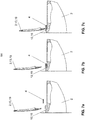
- the hinge receptacles are preferably designed to be open at the top, such that the at least one folding element with its hinge parts can be inserted into the hinge receptacles from above. This means that in an assembly position, the folding element with its hinge parts can enter the hinge receptacles from above are used and then pivoted. When viewed in the installed position, the assembly movement essentially follows the vertical from top to bottom.
- the hinge receptacle and the hinge parts are preferably designed such that a separation between the hinge receptacle and hinge parts is not possible when the folding element pivots out of the mounting position.
- the hinge receptacles and the hinge parts are preferably mechanically connected to one another.
- the mechanical connection is, for example, a locking mechanism or a quick release.
- a quick-release fastener is understood to be a mechanical connection that can be released without the aid of a tool.
- a cylindrical pin is formed with two surfaces and a cylindrical receptacle has a slot through which the pin can be passed if the surfaces are parallel to the slot.
- the mechanical connection can also be made in the EP 2 679 127 disclosed mechanical connection.
- the two hinge parts on the folding element are arranged rigidly to one another via the folding element, wherein if the two hinge parts are in the respective hinge receptacle, the hinge parts form a stop for the clamping sections, such that the clamping sections cannot be disengaged from the toilet bowl when the hinge parts are inserted are.
- hinge parts provide a stop for the clamping sections and prevent the clamping sections from moving away from one another.
- the at least one folding element is preferably a seat ring or a cover.
- a folding element in the form of a seat ring and a folding element in the form of a cover are formed, the hinge parts of the seat ring and the hinge parts of the cover preferably lying in a common hinge seat.
- the fastening element is preferably made of metal, in particular steel. This has the advantage that a defined basis for the folding element can be created.
- An arrangement comprises a toilet bowl, in particular made of ceramic, and a toilet seat arrangement as described above, the toilet bowl having two receptacles, one of the clamping sections protruding into one of the receptacles.
- the receptacles preferably each have an undercut, the clamping sections engaging in the undercut.
- undercut and clamping section is preferably designed in such a way that a bearing is provided via the mold, which prevents relative movement between the clamping element and the toilet bowl in at least one direction.
- the shape is particularly preferred in such a way that movement out of the undercut in the vertical and horizontal directions is prevented.
- the recordings are preferably accessible from two sides lying opposite one another. This means that the clamping sections will each protrude into the receptacles from the outside.
- An elevated area preferably extends away from a support surface on which the at least one folding element rests, the receptacle extending laterally into the raised area, and the space between the two clamping sections being filled by this raised area.
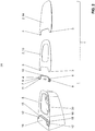
- FIG. 1 a perspective view of a toilet bowl 5 with a toilet seat arrangement 1 is shown.
- the toilet seat arrangement 1 is mechanically connected to the toilet bowl 5.
- the toilet seat arrangement 1 comprises at least one folding element 2 and a fastening element 4, with which the at least one folding element 2 can be connected to the toilet bowl 5.
- the at least one folding element 2 is connected to the toilet bowl 5 via the fastening element 4 and is pivotably mounted on the fastening element 4.
- two folding elements 2 are shown, namely a seat ring 13 and a cover 14.
- the at least one folding element 2 comprises two hinge parts 3 which are spaced apart from one another.
- the at least one folding element 2 is pivotably connected to the fastening element 4 via the hinge parts 3, whereby the at least one folding element 2 can be pivotably connected to the toilet bowl 5.
- the folding element 2 can be swiveled upwards from a support surface 18 of the toilet bowl 5.
- the bearing surface 18 surrounds the interior 20 of the toilet bowl 5.
- the fastening element 4 has a first hinge receptacle 5 for one of the two hinge parts 3 and a second hinge receptacle 7 for the other of the two hinge parts 3. Furthermore, the fastening element 4 has two clamping sections 8, 9, with which the fastening element 4 can be clamped to the toilet bowl 5.
- the toilet bowl 5 has two receptacles 15, in which the clamping sections 8, 9 engage. This means that the fastening element 4 can be clamped to the toilet bowl 5 via the two clamping sections 8, 9 and thus forms a base for receiving the at least one folding element 2, which can be pivoted with the fastening element 4 via the hinge parts 3 and the hinge receptacle 6, 7 Can be connected.
- a hinge part 3 from the seat ring 13 and a hinge part from the cover 14 are each mounted in a common hinge receptacle 6, 7.
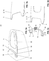
- the Figures 3a to 3d show the individual elements of the toilet seat assembly 1 in detail.
- the Figure 3a shows the toilet bowl that Figure 3b the rear end of the lid 14, the Figure 3c the fastener and the Figure 3d the rear end of the seat ring 13.
- the two clamping sections 8, 9 are connected via a resilient rod 10.
- the rod 10 is designed here as a bending rod and can be easily deformed when the fastening element 4 is installed.
- the hinge receptacles 6, 7, the clamping sections 8, 9 and the rod 10 are formed in one piece. This means that the fastening element 4 consists of one piece.
- the two hinge receptacles 6, 7 lie on the outside of the respective clamping section 8, 9 and thus adjoin the clamping section 8, 9.
- the two clamping sections 8, 9 and the two hinge receptacles 6, 7 each project from one end to a transverse side of the rod. Between the two clamping sections 8, 9 there is an intermediate space Z, in which parts of the toilet bowl 5 are received. Here, a rear area 19 of the toilet bowl 5 projects into the intermediate space Z and essentially fills it completely.
- the two clamping sections 8, 9 lie opposite one another with respect to the intermediate space Z.
- the rod 2 is designed such that the two clamping sections are resilient from an initial position and in the Figure 3c shown, are movable into an assembly position.
- the clamping sections 8, 9 are slightly bent outwards along the arrows P, as a result of which the intermediate space Z is enlarged.
- the clamping sections 8, 9 are in a clamping position.
- the clamping position is such that it is spatially located between the starting position and the mounting position.
- the clamping position is selected such that, due to the spring force provided by the resilient rod 2, a clamping force K can be provided with which the fastening element 4 can be clamped to the toilet bowl 5.
- the clamping force K is indicated by arrows in the Figure 5 symbolizes. This means that the fastening element 4 is connected to the toilet bowl 5 under tension and is under mechanical tension after the connection has been made.
- the two clamping sections 8, 9 are provided with a bulging surface 11 on a side facing the rod 10.
- the bulging surface 11 protrudes into the intermediate space Z or is bulged toward the intermediate space Z. This means that the space Z between the two clamping sections 8, 9 becomes slightly smaller in the region of the bulging surface 11 due to the bulging surface 11.
- the bulging surface 11 protrudes into an undercut 12 of the receptacle 15.
- the undercut 12 then works together with the bulging surface 11, so that Folding element 2 and the fastening element 4 cannot easily be separated from the toilet bowl 5.
- the rod 10 merges into the respective clamping section.
- the arc-shaped area bears the reference numeral 16.
- the rod 10 itself is designed as a bending rod between the two arcuate regions 16. In the bending area, which bears the reference number 17, the rod is slightly bent when the fastening element 4 is installed.
- the rod has a rectangular cross section in the embodiment shown. The cross section can also be different.
- the bending region 17 extends in the embodiment shown along a straight line.
- the rod can also extend here along an arc line.
- the fastening element 4 is in relation to a plane of symmetry S which runs transversely and centrally through the rod 10 and which is in the Figure 3c is drawn symmetrically.
- This is a mirror symmetry with respect to the plane of symmetry S. That is, the part of the rod 10 to the left of the plane of symmetry S, as well as the hinge receptacle 6 and the clamping section 8 are essentially mirror-inverted to the part of the rod 10 to the right of the plane of symmetry S. as well as the second hinge receptacle 7 and the clamping section 9.
- the hinge receptacles 6, 7 lie on the outside of the respective clamping section 8, 9. That is, the clamping section 8, 9 lies on the inside on the hinge receptacles 6, 7.
- a reverse arrangement is also conceivable.
- the hinge receptacles 6, 7 are open at the top.
- the open design is such that the at least one flap element 2 with its hinge parts 3 can be inserted into the hinge receptacle 6, 7 in a vertical direction from above.
- the The vertical direction is essentially perpendicular to the contact surface 18.
- the hinge parts 3 are preferably pivotably mounted in the respective hinge receptacle 6, 7 via a mechanical connection.
- the mechanical connection can be a locking mechanism or a quick release.
- the mechanical connection can preferably be removed without tools, so that the separation between the folding element 2 and the fastening element 4 can be easily removed.
- the two hinge parts 3 are fixedly arranged on at least one folding element 2 and are rigid with respect to one another.
- the two hinge parts 3 of the seat ring 13 in the embodiment shown act as a stop for the clamping sections 8, 9. If the two hinge parts 3 lie in the respective hinge receptacle 6, 7, the hinge parts 3 form a stop for the clamping sections 8, 9.
- the stop is formed in such a way that the clamping sections 8, 9 cannot be moved out of engagement with the receptacle 15 of the toilet bowl 5 when the hinge parts 3 are inserted. A movement against the direction of the clamping force K is therefore not possible when hinge parts 3 are inserted.
- undercut 12 and clamping section 8, 9 is designed in the embodiment shown such that a relative movement between fastening element 4 and toilet bowl 5 can be prevented both in the vertical direction V and in the horizontal direction H.
- the shape of the undercut 12 and the clamping section 8, 9 is selected such that said movement can be prevented.
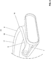
- the undercut 12 preferably projects, as from FIGS Figures 5 and 6 It can be seen with respect to a rear direction 19 transversely to a vertical direction V and also transversely to a horizontal direction H in the rear region 19.
- an undercut 12 can be created which is undercut in two directions.
- the fastening element 4 is preferably made of metal, in particular steel.
- the toilet bowl 5 has two receptacles 15 in the embodiment shown.
- One of the clamping sections 8, 9 projects into one of the receptacles 15.
- the receptacles 15 are formed here by side surfaces on a rear area 19 of the toilet bowl 5.
- the rear region 19 is raised from the support surface 18.
- the receptacles 15 are still open on the outside.
- the rear area 19 between the receptacles 15 comes to lie in the space Z of the fastening element 4.
Landscapes
- Health & Medical Sciences (AREA)
- Public Health (AREA)
- Toilet Supplies (AREA)
Priority Applications (2)
| Application Number | Priority Date | Filing Date | Title |
|---|---|---|---|
| EP17199147.4A EP3476264B1 (de) | 2017-10-30 | 2017-10-30 | Toilettensitzanordnung |
| PL17199147T PL3476264T3 (pl) | 2017-10-30 | 2017-10-30 | Zespół deski sedesowej |
Applications Claiming Priority (1)
| Application Number | Priority Date | Filing Date | Title |
|---|---|---|---|
| EP17199147.4A EP3476264B1 (de) | 2017-10-30 | 2017-10-30 | Toilettensitzanordnung |
Publications (2)
| Publication Number | Publication Date |
|---|---|
| EP3476264A1 EP3476264A1 (de) | 2019-05-01 |
| EP3476264B1 true EP3476264B1 (de) | 2020-05-27 |
Family
ID=60191251
Family Applications (1)
| Application Number | Title | Priority Date | Filing Date |
|---|---|---|---|
| EP17199147.4A Active EP3476264B1 (de) | 2017-10-30 | 2017-10-30 | Toilettensitzanordnung |
Country Status (2)
| Country | Link |
|---|---|
| EP (1) | EP3476264B1 (pl) |
| PL (1) | PL3476264T3 (pl) |
Family Cites Families (6)
| Publication number | Priority date | Publication date | Assignee | Title |
|---|---|---|---|---|
| IT1090104B (it) * | 1977-10-06 | 1985-06-18 | Ics Cidneo Spa | Perfezionamenti al coperchio per vasi igienici |
| EP1699336A1 (fr) | 2003-12-09 | 2006-09-13 | MAUDUIT, Daniel | Toilettes a palier d une piece avec la cuvette |
| FR2898033B1 (fr) | 2006-03-02 | 2010-07-30 | Daniel Mauduit | Toilettes a palier et tourillon munis de moyens d'attraction magnetique |
| CN201710270U (zh) * | 2010-04-09 | 2011-01-19 | 陈焕斌 | 方便拆卸盖的马桶 |
| DK2679127T3 (da) | 2012-06-28 | 2014-05-05 | Geberit Int Ag | WC-komponenter og WC med aftageligt hængsel |
| CN203302979U (zh) * | 2013-05-02 | 2013-11-27 | 周裕佳 | 一种马桶按键结构 |
-
2017
- 2017-10-30 PL PL17199147T patent/PL3476264T3/pl unknown
- 2017-10-30 EP EP17199147.4A patent/EP3476264B1/de active Active
Non-Patent Citations (1)
| Title |
|---|
| None * |
Also Published As
| Publication number | Publication date |
|---|---|
| EP3476264A1 (de) | 2019-05-01 |
| PL3476264T3 (pl) | 2021-04-06 |
Similar Documents
| Publication | Publication Date | Title |
|---|---|---|
| DE2812665C2 (de) | Vorrichtung zum Befestigen und Spannen eines dünnen Films | |
| DE69100219T2 (de) | Verbindungsstück für längliche Elemente. | |
| EP0749378B1 (de) | Wischblatt | |
| DE102014005286B3 (de) | Befestigungsvorrichtung, Aufhängevorrichtung und Verfahren zum Montieren einer Aufhängevorrichtung | |
| DE2741061A1 (de) | Befestigungselement | |
| EP3797662B1 (de) | Kippdübel | |
| DE19631509A1 (de) | Flexibler Spannverschluß | |
| DE9407618U1 (de) | Befestigungsvorrichtung für Leitungen | |
| EP4169131B1 (de) | Steckverbinder umfassend einen kontaktträger mit zwei benachbarten haltestegen | |
| EP3776772B1 (de) | Trennsteg für eine energieführungskette | |
| EP3183467B1 (de) | Aggregatlager-anordnung | |
| DE102024107214A1 (de) | Befestigungselement | |
| DE19817849A1 (de) | Kipphebel | |
| DE102018123321A1 (de) | Wischerhalter und Wischer | |
| EP0070400B1 (de) | Schraubzwinge | |
| EP3476264B1 (de) | Toilettensitzanordnung | |
| EP2721983B1 (de) | Halteeinrichtung zur Montage an Duschstangen | |
| EP3825481B1 (de) | Spülwasserverteiler | |
| DE102019114519B4 (de) | Montagesystem mit Justiermöglichkeit, Gepäckfach sowie Fahrzeug mit Montagesystem und Verfahren zur Installation und Justierung eines Bauteils | |
| DE69011489T2 (de) | Verbindungselemente für Rückenlehnen mit dazugehörigen Sitzen. | |
| DE202020104251U1 (de) | Scharnier zur beweglichen Verbindung eines beweglichen Möbelteils an einen Möbelkorpus | |
| DE69329892T2 (de) | Wärmetauscher mit, mit Stützen verbundenen, Wasserkästen insbesondere für Fahrzeuge | |
| DE102024124552B3 (de) | Befestigungsanordnung zwischen einem Halter und einer Kabeltragkomponente sowie Halter mit einem daran angeschlossenen Anschlussadapter | |
| CH716364B1 (de) | Spülwasserverteiler für einen Sanitärartikel. | |
| EP3797659B1 (de) | Befestigungsvorrichtung |
Legal Events
| Date | Code | Title | Description |
|---|---|---|---|
| PUAI | Public reference made under article 153(3) epc to a published international application that has entered the european phase |
Free format text: ORIGINAL CODE: 0009012 |
|
| STAA | Information on the status of an ep patent application or granted ep patent |
Free format text: STATUS: THE APPLICATION HAS BEEN PUBLISHED |
|
| AK | Designated contracting states |
Kind code of ref document: A1 Designated state(s): AL AT BE BG CH CY CZ DE DK EE ES FI FR GB GR HR HU IE IS IT LI LT LU LV MC MK MT NL NO PL PT RO RS SE SI SK SM TR |
|
| AX | Request for extension of the european patent |
Extension state: BA ME |
|
| STAA | Information on the status of an ep patent application or granted ep patent |
Free format text: STATUS: REQUEST FOR EXAMINATION WAS MADE |
|
| 17P | Request for examination filed |
Effective date: 20190902 |
|
| RBV | Designated contracting states (corrected) |
Designated state(s): AL AT BE BG CH CY CZ DE DK EE ES FI FR GB GR HR HU IE IS IT LI LT LU LV MC MK MT NL NO PL PT RO RS SE SI SK SM TR |
|
| GRAP | Despatch of communication of intention to grant a patent |
Free format text: ORIGINAL CODE: EPIDOSNIGR1 |
|
| STAA | Information on the status of an ep patent application or granted ep patent |
Free format text: STATUS: GRANT OF PATENT IS INTENDED |
|
| INTG | Intention to grant announced |
Effective date: 20191129 |
|
| GRAS | Grant fee paid |
Free format text: ORIGINAL CODE: EPIDOSNIGR3 |
|
| GRAJ | Information related to disapproval of communication of intention to grant by the applicant or resumption of examination proceedings by the epo deleted |
Free format text: ORIGINAL CODE: EPIDOSDIGR1 |
|
| GRAL | Information related to payment of fee for publishing/printing deleted |
Free format text: ORIGINAL CODE: EPIDOSDIGR3 |
|
| STAA | Information on the status of an ep patent application or granted ep patent |
Free format text: STATUS: REQUEST FOR EXAMINATION WAS MADE |
|
| GRAR | Information related to intention to grant a patent recorded |
Free format text: ORIGINAL CODE: EPIDOSNIGR71 |
|
| STAA | Information on the status of an ep patent application or granted ep patent |
Free format text: STATUS: GRANT OF PATENT IS INTENDED |
|
| GRAA | (expected) grant |
Free format text: ORIGINAL CODE: 0009210 |
|
| STAA | Information on the status of an ep patent application or granted ep patent |
Free format text: STATUS: THE PATENT HAS BEEN GRANTED |
|
| INTC | Intention to grant announced (deleted) | ||
| AK | Designated contracting states |
Kind code of ref document: B1 Designated state(s): AL AT BE BG CH CY CZ DE DK EE ES FI FR GB GR HR HU IE IS IT LI LT LU LV MC MK MT NL NO PL PT RO RS SE SI SK SM TR |
|
| INTG | Intention to grant announced |
Effective date: 20200421 |
|
| REG | Reference to a national code |
Ref country code: GB Ref legal event code: FG4D Free format text: NOT ENGLISH |
|
| REG | Reference to a national code |
Ref country code: CH Ref legal event code: EP |
|
| REG | Reference to a national code |
Ref country code: DE Ref legal event code: R096 Ref document number: 502017005435 Country of ref document: DE |
|
| REG | Reference to a national code |
Ref country code: AT Ref legal event code: REF Ref document number: 1273635 Country of ref document: AT Kind code of ref document: T Effective date: 20200615 |
|
| REG | Reference to a national code |
Ref country code: CH Ref legal event code: NV Representative=s name: ISLER AND PEDRAZZINI AG, CH |
|
| REG | Reference to a national code |
Ref country code: LT Ref legal event code: MG4D |
|
| PG25 | Lapsed in a contracting state [announced via postgrant information from national office to epo] |
Ref country code: LT Free format text: LAPSE BECAUSE OF FAILURE TO SUBMIT A TRANSLATION OF THE DESCRIPTION OR TO PAY THE FEE WITHIN THE PRESCRIBED TIME-LIMIT Effective date: 20200527 Ref country code: SE Free format text: LAPSE BECAUSE OF FAILURE TO SUBMIT A TRANSLATION OF THE DESCRIPTION OR TO PAY THE FEE WITHIN THE PRESCRIBED TIME-LIMIT Effective date: 20200527 Ref country code: FI Free format text: LAPSE BECAUSE OF FAILURE TO SUBMIT A TRANSLATION OF THE DESCRIPTION OR TO PAY THE FEE WITHIN THE PRESCRIBED TIME-LIMIT Effective date: 20200527 Ref country code: PT Free format text: LAPSE BECAUSE OF FAILURE TO SUBMIT A TRANSLATION OF THE DESCRIPTION OR TO PAY THE FEE WITHIN THE PRESCRIBED TIME-LIMIT Effective date: 20200928 Ref country code: IS Free format text: LAPSE BECAUSE OF FAILURE TO SUBMIT A TRANSLATION OF THE DESCRIPTION OR TO PAY THE FEE WITHIN THE PRESCRIBED TIME-LIMIT Effective date: 20200927 Ref country code: GR Free format text: LAPSE BECAUSE OF FAILURE TO SUBMIT A TRANSLATION OF THE DESCRIPTION OR TO PAY THE FEE WITHIN THE PRESCRIBED TIME-LIMIT Effective date: 20200828 Ref country code: NO Free format text: LAPSE BECAUSE OF FAILURE TO SUBMIT A TRANSLATION OF THE DESCRIPTION OR TO PAY THE FEE WITHIN THE PRESCRIBED TIME-LIMIT Effective date: 20200827 |
|
| REG | Reference to a national code |
Ref country code: NL Ref legal event code: MP Effective date: 20200527 |
|
| PG25 | Lapsed in a contracting state [announced via postgrant information from national office to epo] |
Ref country code: LV Free format text: LAPSE BECAUSE OF FAILURE TO SUBMIT A TRANSLATION OF THE DESCRIPTION OR TO PAY THE FEE WITHIN THE PRESCRIBED TIME-LIMIT Effective date: 20200527 Ref country code: RS Free format text: LAPSE BECAUSE OF FAILURE TO SUBMIT A TRANSLATION OF THE DESCRIPTION OR TO PAY THE FEE WITHIN THE PRESCRIBED TIME-LIMIT Effective date: 20200527 Ref country code: BG Free format text: LAPSE BECAUSE OF FAILURE TO SUBMIT A TRANSLATION OF THE DESCRIPTION OR TO PAY THE FEE WITHIN THE PRESCRIBED TIME-LIMIT Effective date: 20200827 Ref country code: HR Free format text: LAPSE BECAUSE OF FAILURE TO SUBMIT A TRANSLATION OF THE DESCRIPTION OR TO PAY THE FEE WITHIN THE PRESCRIBED TIME-LIMIT Effective date: 20200527 |
|
| PG25 | Lapsed in a contracting state [announced via postgrant information from national office to epo] |
Ref country code: NL Free format text: LAPSE BECAUSE OF FAILURE TO SUBMIT A TRANSLATION OF THE DESCRIPTION OR TO PAY THE FEE WITHIN THE PRESCRIBED TIME-LIMIT Effective date: 20200527 Ref country code: AL Free format text: LAPSE BECAUSE OF FAILURE TO SUBMIT A TRANSLATION OF THE DESCRIPTION OR TO PAY THE FEE WITHIN THE PRESCRIBED TIME-LIMIT Effective date: 20200527 |
|
| PG25 | Lapsed in a contracting state [announced via postgrant information from national office to epo] |
Ref country code: CZ Free format text: LAPSE BECAUSE OF FAILURE TO SUBMIT A TRANSLATION OF THE DESCRIPTION OR TO PAY THE FEE WITHIN THE PRESCRIBED TIME-LIMIT Effective date: 20200527 Ref country code: RO Free format text: LAPSE BECAUSE OF FAILURE TO SUBMIT A TRANSLATION OF THE DESCRIPTION OR TO PAY THE FEE WITHIN THE PRESCRIBED TIME-LIMIT Effective date: 20200527 Ref country code: SM Free format text: LAPSE BECAUSE OF FAILURE TO SUBMIT A TRANSLATION OF THE DESCRIPTION OR TO PAY THE FEE WITHIN THE PRESCRIBED TIME-LIMIT Effective date: 20200527 Ref country code: EE Free format text: LAPSE BECAUSE OF FAILURE TO SUBMIT A TRANSLATION OF THE DESCRIPTION OR TO PAY THE FEE WITHIN THE PRESCRIBED TIME-LIMIT Effective date: 20200527 Ref country code: DK Free format text: LAPSE BECAUSE OF FAILURE TO SUBMIT A TRANSLATION OF THE DESCRIPTION OR TO PAY THE FEE WITHIN THE PRESCRIBED TIME-LIMIT Effective date: 20200527 Ref country code: ES Free format text: LAPSE BECAUSE OF FAILURE TO SUBMIT A TRANSLATION OF THE DESCRIPTION OR TO PAY THE FEE WITHIN THE PRESCRIBED TIME-LIMIT Effective date: 20200527 |
|
| PG25 | Lapsed in a contracting state [announced via postgrant information from national office to epo] |
Ref country code: SK Free format text: LAPSE BECAUSE OF FAILURE TO SUBMIT A TRANSLATION OF THE DESCRIPTION OR TO PAY THE FEE WITHIN THE PRESCRIBED TIME-LIMIT Effective date: 20200527 |
|
| REG | Reference to a national code |
Ref country code: DE Ref legal event code: R097 Ref document number: 502017005435 Country of ref document: DE |
|
| PLBE | No opposition filed within time limit |
Free format text: ORIGINAL CODE: 0009261 |
|
| STAA | Information on the status of an ep patent application or granted ep patent |
Free format text: STATUS: NO OPPOSITION FILED WITHIN TIME LIMIT |
|
| 26N | No opposition filed |
Effective date: 20210302 |
|
| PG25 | Lapsed in a contracting state [announced via postgrant information from national office to epo] |
Ref country code: SI Free format text: LAPSE BECAUSE OF FAILURE TO SUBMIT A TRANSLATION OF THE DESCRIPTION OR TO PAY THE FEE WITHIN THE PRESCRIBED TIME-LIMIT Effective date: 20200527 |
|
| PG25 | Lapsed in a contracting state [announced via postgrant information from national office to epo] |
Ref country code: LU Free format text: LAPSE BECAUSE OF NON-PAYMENT OF DUE FEES Effective date: 20201030 Ref country code: MC Free format text: LAPSE BECAUSE OF FAILURE TO SUBMIT A TRANSLATION OF THE DESCRIPTION OR TO PAY THE FEE WITHIN THE PRESCRIBED TIME-LIMIT Effective date: 20200527 |
|
| REG | Reference to a national code |
Ref country code: BE Ref legal event code: MM Effective date: 20201031 |
|
| PG25 | Lapsed in a contracting state [announced via postgrant information from national office to epo] |
Ref country code: BE Free format text: LAPSE BECAUSE OF NON-PAYMENT OF DUE FEES Effective date: 20201031 |
|
| PG25 | Lapsed in a contracting state [announced via postgrant information from national office to epo] |
Ref country code: IE Free format text: LAPSE BECAUSE OF NON-PAYMENT OF DUE FEES Effective date: 20201030 |
|
| PGFP | Annual fee paid to national office [announced via postgrant information from national office to epo] |
Ref country code: PL Payment date: 20210921 Year of fee payment: 5 |
|
| PGFP | Annual fee paid to national office [announced via postgrant information from national office to epo] |
Ref country code: DE Payment date: 20211020 Year of fee payment: 5 |
|
| PGFP | Annual fee paid to national office [announced via postgrant information from national office to epo] |
Ref country code: IT Payment date: 20211022 Year of fee payment: 5 Ref country code: FR Payment date: 20211022 Year of fee payment: 5 Ref country code: CH Payment date: 20211013 Year of fee payment: 5 |
|
| PG25 | Lapsed in a contracting state [announced via postgrant information from national office to epo] |
Ref country code: TR Free format text: LAPSE BECAUSE OF FAILURE TO SUBMIT A TRANSLATION OF THE DESCRIPTION OR TO PAY THE FEE WITHIN THE PRESCRIBED TIME-LIMIT Effective date: 20200527 Ref country code: MT Free format text: LAPSE BECAUSE OF FAILURE TO SUBMIT A TRANSLATION OF THE DESCRIPTION OR TO PAY THE FEE WITHIN THE PRESCRIBED TIME-LIMIT Effective date: 20200527 Ref country code: CY Free format text: LAPSE BECAUSE OF FAILURE TO SUBMIT A TRANSLATION OF THE DESCRIPTION OR TO PAY THE FEE WITHIN THE PRESCRIBED TIME-LIMIT Effective date: 20200527 |
|
| GBPC | Gb: european patent ceased through non-payment of renewal fee |
Effective date: 20211030 |
|
| PG25 | Lapsed in a contracting state [announced via postgrant information from national office to epo] |
Ref country code: MK Free format text: LAPSE BECAUSE OF FAILURE TO SUBMIT A TRANSLATION OF THE DESCRIPTION OR TO PAY THE FEE WITHIN THE PRESCRIBED TIME-LIMIT Effective date: 20200527 |
|
| PG25 | Lapsed in a contracting state [announced via postgrant information from national office to epo] |
Ref country code: GB Free format text: LAPSE BECAUSE OF NON-PAYMENT OF DUE FEES Effective date: 20211030 |
|
| REG | Reference to a national code |
Ref country code: DE Ref legal event code: R119 Ref document number: 502017005435 Country of ref document: DE |
|
| REG | Reference to a national code |
Ref country code: CH Ref legal event code: PL |
|
| PG25 | Lapsed in a contracting state [announced via postgrant information from national office to epo] |
Ref country code: LI Free format text: LAPSE BECAUSE OF NON-PAYMENT OF DUE FEES Effective date: 20221031 Ref country code: FR Free format text: LAPSE BECAUSE OF NON-PAYMENT OF DUE FEES Effective date: 20221031 Ref country code: DE Free format text: LAPSE BECAUSE OF NON-PAYMENT OF DUE FEES Effective date: 20230503 Ref country code: CH Free format text: LAPSE BECAUSE OF NON-PAYMENT OF DUE FEES Effective date: 20221031 |
|
| PG25 | Lapsed in a contracting state [announced via postgrant information from national office to epo] |
Ref country code: IT Free format text: LAPSE BECAUSE OF NON-PAYMENT OF DUE FEES Effective date: 20221030 |
|
| REG | Reference to a national code |
Ref country code: AT Ref legal event code: MM01 Ref document number: 1273635 Country of ref document: AT Kind code of ref document: T Effective date: 20221030 |
|
| PG25 | Lapsed in a contracting state [announced via postgrant information from national office to epo] |
Ref country code: AT Free format text: LAPSE BECAUSE OF NON-PAYMENT OF DUE FEES Effective date: 20221030 |
|
| PG25 | Lapsed in a contracting state [announced via postgrant information from national office to epo] |
Ref country code: PL Free format text: LAPSE BECAUSE OF NON-PAYMENT OF DUE FEES Effective date: 20221030 |
|
| PG25 | Lapsed in a contracting state [announced via postgrant information from national office to epo] |
Ref country code: PL Free format text: LAPSE BECAUSE OF NON-PAYMENT OF DUE FEES Effective date: 20221030 |