EP3475922B1 - Verfahren und fahrzeugsteuersystem zum erzeugen von abbildungen eines umfeldmodells und entsprechendes fahrzeug - Google Patents
Verfahren und fahrzeugsteuersystem zum erzeugen von abbildungen eines umfeldmodells und entsprechendes fahrzeug Download PDFInfo
- Publication number
- EP3475922B1 EP3475922B1 EP17755058.9A EP17755058A EP3475922B1 EP 3475922 B1 EP3475922 B1 EP 3475922B1 EP 17755058 A EP17755058 A EP 17755058A EP 3475922 B1 EP3475922 B1 EP 3475922B1
- Authority
- EP
- European Patent Office
- Prior art keywords
- camera
- vehicle
- movement path
- reference point
- camera parameters
- Prior art date
- Legal status (The legal status is an assumption and is not a legal conclusion. Google has not performed a legal analysis and makes no representation as to the accuracy of the status listed.)
- Active
Links
Images


Classifications
-
- G—PHYSICS
- G06—COMPUTING OR CALCULATING; COUNTING
- G06T—IMAGE DATA PROCESSING OR GENERATION, IN GENERAL
- G06T19/00—Manipulating three-dimensional [3D] models or images for computer graphics
- G06T19/003—Navigation within 3D models or images
-
- H—ELECTRICITY
- H04—ELECTRIC COMMUNICATION TECHNIQUE
- H04N—PICTORIAL COMMUNICATION, e.g. TELEVISION
- H04N23/00—Cameras or camera modules comprising electronic image sensors; Control thereof
- H04N23/50—Constructional details
- H04N23/54—Mounting of pick-up tubes, electronic image sensors, deviation or focusing coils
-
- G—PHYSICS
- G06—COMPUTING OR CALCULATING; COUNTING
- G06T—IMAGE DATA PROCESSING OR GENERATION, IN GENERAL
- G06T2200/00—Indexing scheme for image data processing or generation, in general
- G06T2200/04—Indexing scheme for image data processing or generation, in general involving 3D image data
-
- G—PHYSICS
- G06—COMPUTING OR CALCULATING; COUNTING
- G06T—IMAGE DATA PROCESSING OR GENERATION, IN GENERAL
- G06T2200/00—Indexing scheme for image data processing or generation, in general
- G06T2200/08—Indexing scheme for image data processing or generation, in general involving all processing steps from image acquisition to 3D model generation
Definitions
- the present invention relates to a method and a vehicle control system for a vehicle for generating continuous images of a stored three-dimensional model of the surroundings of a vehicle and to a vehicle.
- Environment models for vehicles such as from the WO 2013/060323 A1 known, provide information about objects in the surroundings of the vehicle and thereby allow a driver or a driver assistance system to recognize drivable areas.
- SEIYA SHIMIZU ET AL "Wraparound View System for Motor Vehicles "describes a method for generating 360 images of a stored three-dimensional environment model (31) of a vehicle, the view of a virtual camera being animated from a point A to a point B.”
- This object is achieved by a method for generating continuous images of a stored three-dimensional environment model of a vehicle with the Features of claim 1, a vehicle control system of a vehicle for generating continuous images of a stored three-dimensional model of the surroundings of the vehicle with the features of claim 10 and by a vehicle with the features of claim 15.
- the invention accordingly creates a method for generating continuous images of a stored three-dimensional model of the surroundings of a vehicle.
- At least one camera image is generated by a camera device of the vehicle and the generated camera image is projected onto a projection surface in the stored three-dimensional model of the surroundings of the vehicle.
- Continuous images of the projection surface are generated and the generated continuous images are output by means of a virtual camera that can be moved in the environment model.
- the virtual camera here includes a set of camera parameters, the elements of which include a camera position of the virtual camera and an optical axis of the virtual camera.
- the set of camera parameters of the virtual camera is interpolated between a predetermined first set of camera parameters and a second set of camera parameters along a first movement path in the environment model.
- the set of camera parameters of the virtual camera is continuously interpolated between the second set of camera parameters and a predefined third set of camera parameters along a second movement path in the environment model. That optical axis of the virtual camera, which is an element of the second set of camera parameters, is determined in such a way that it runs through a predefined axis point which lies on a connecting path between a first reference point and a second reference point.
- the first reference point is a predetermined point on that optical axis of the virtual camera which is an element of the first set of camera parameters.
- the second reference point is a predetermined point of that optical axis of the virtual camera which is an element of the third set of camera parameters.
- An image of the environment model is understood to mean an image of a specific spatial sub-area of the environment model generated by means of the virtual camera, the image being dependent on a position and orientation of the virtual camera.
- the projection surface is to be understood as a two-dimensional hypersurface in the three-dimensional environment model, which can be shaped and curved as desired.
- the projection surface can be, for example, a flat plane, a spherical shell segment, a cylindrical surface or a paraboloidal or hyperboloidal surface.
- the optical axes extend from the corresponding camera position in the detection direction of the virtual camera.
- the optical axes of the first and third sets of camera parameters are preferably aligned with the projection surface.
- the invention makes it possible to use the first and third set of camera parameters to specify a start and end position of the virtual camera with corresponding orientations, between which there is continuous interpolation.
- the second set of camera parameters defines an additional interpolation point so that the interpolation path is divided into the first and second movement paths.
- the camera parameters specified at the support point are selected by the construction according to the invention in such a way that the interpolation prevents the orientation of the virtual camera from changing in such a way that it is aligned with an area of the environment model that cannot be displayed or is not provided with image information.
- the inventive Method thus enables the generation of continuous images.
- the method according to the invention increases safety, since correct and uninterrupted, that is to say continuous, images are displayed to the driver and the driver can thereby better assess the road situation.
- the method is particularly advantageous in combination with a driver assistance system which controls the vehicle semi-autonomously or autonomously and is therefore dependent on correct information on the surroundings.
- the first movement path and the second movement path describe a segment of a circle. This enables particularly simple interpolation of the camera parameters.
- the interpolation of the camera position of the movable virtual camera along the first movement path and / or along the second movement path is carried out by spherical linear interpolation (SLERP).
- SLERP spherical linear interpolation
- the interpolation of the optical axis of the movable virtual camera along the first movement path and / or along the second movement path is carried out by spherical linear interpolation (SLERP).
- SLERP spherical linear interpolation
- the camera position which is an element of the second set of camera parameters, lies in a middle third of the circle segment and in particular on a middle point of the circle segment.
- a distance of the first reference point from that camera position which is an element of the first set of camera parameters is essentially the same as a distance of the second reference point from that camera position which is an element of the third set of camera parameters.
- the predetermined connection point lies essentially in a center of the connection path between the first reference point and the second reference point.
- a driver assistance system controls a vehicle function of the vehicle on the basis of the continuous images that are output.
- the vehicle functions can include activating and activating or deactivating actuators, such as indicators or side mirrors, or also semi-autonomous or autonomous acceleration, braking or steering of the vehicle.
- the output continuous images are displayed to a driver of the vehicle on a display device.
- the invention relates to a vehicle control system of a vehicle for generating continuous images of a stored three-dimensional model of the surroundings of the vehicle.
- the vehicle control system comprises a camera device of the vehicle for generating at least one camera image and a computing device.
- the computing device is designed to transfer the generated camera image to a To project the projection surface in the stored three-dimensional model of the surroundings of the vehicle, and to generate continuous images of the projection surface by means of a movable virtual camera.
- the vehicle control system further comprises an output device which is designed to output the continuous images generated.
- the virtual camera has a set of camera parameters, the elements of which include a camera position of the virtual camera and an optical axis of the virtual camera.
- the computing device is designed to continuously interpolate the set of camera parameters along a first movement path in the environment model between a predetermined first set of camera parameters and a second set of camera parameters. Furthermore, the computing device is designed to continuously interpolate the camera parameters of the virtual camera along a second movement path in the environment model between the second set of camera parameters and a predefined third set of camera parameters. The computing device is further designed to determine that optical axis of the virtual camera, which is an element of the second set of camera parameters, in such a way that it runs through a predetermined axis point which lies on a connecting route between a first reference point and a second reference point .
- the first reference point is a predetermined point on that optical axis of the virtual camera that is an element of the first set of camera parameters. Furthermore, the second reference point is a predetermined point on that optical axis of the virtual camera which is an element of the third set of camera parameters.
- the computing device is preferably designed to determine the axis point, the first reference point and the second reference point.
- the first movement path and describe the second movement path in the environment model is a segment of a circle.
- the computing device is designed to interpolate the camera position of the movable virtual camera along the first movement path and / or along the second movement path by spherical linear interpolation (SLERP).
- SLERP spherical linear interpolation
- the vehicle control system comprises a driver assistance system which is designed to control a vehicle function of the vehicle on the basis of the continuous images that are output.
- the output device comprises a display device which is designed to display the output continuous images to a driver of the vehicle.
- the present invention relates to a vehicle with a vehicle control system.
- Figure 1 shows a flowchart to explain a method for generating continuous images of a stored three-dimensional environment model of a vehicle according to an embodiment of the invention.
- FIG. 2 A scenario is illustrated which shows a top view of a vehicle 21 with a camera device 22.
- the camera device 22 of the vehicle 21 comprises a multiplicity of vehicle cameras 22a to 22d which are arranged around the vehicle 21 and enable a surround view view.
- a first method step S1 at least one camera image is generated by the camera device 22 of the vehicle 21.
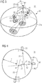
- FIG. 3 Illustrated three-dimensional environment model 31 provided, in which a two-dimensional projection surface 32a is defined.
- the projection surface 32a can represent, for example, a flat hyperplane or a cylinder surface in the environment model 31.
- the projection surface 32a corresponds to an in Figure 3 depicted surface of a bowl-shaped lower hemisphere of a sphere 32.
- a spatial position of the vehicle 21 in the environment model 31 preferably corresponds to a center z of the sphere 32.
- the camera image generated is projected onto the projection surface 32a. If the at least one camera image forms a surround view of the vehicle surroundings, the at least one camera image is projected onto the entire projection surface 32a. According to one embodiment, however, the generated camera image can also only be imaged or projected onto a partial area of the projection surface 32a.
- step S3 continuous images of the projection surface 32a are generated by means of a movable virtual camera 33.
- step S4 the generated continuous images are output.
- the virtual camera 33 has a set of camera parameters or is characterized by these camera parameters. Elements of the set of camera parameters include a camera position of the virtual camera 33 and an optical axis of the virtual camera 33.
- the virtual camera 33 is characterized in three configurations, which are characterized by a first set M1 of camera parameters with a corresponding camera position P1 and optical axis A1, a second set M2 of camera parameters with a corresponding camera position P2 and optical axis A2, and a third set M3 of camera parameters are marked with the corresponding camera position P3 and optical axis A3.
- the first set M1 of camera parameters and the third set M3 of camera parameters are fixed and correspond to an initial configuration or final configuration of the virtual camera 33.
- the second set M2 corresponds to an auxiliary configuration which enables correct interpolation between the initial configuration and the final configuration.
- the camera positions P1 to P3 of the first to third sets M1 to M3 lie on a great circle which extends on a surface 32b of an upper hemisphere of the sphere 32.
- This surface 32b indicates the possible camera positions of the virtual camera 33, that is, the virtual camera 33 is in principle freely displaceable or movable on the surface 32b.
- the camera position can then be specified, for example, by specifying coordinates x, y, z of the environment model 31.
- the camera position is preferably indicated by spherical coordinates r, ⁇ , ⁇ , where r corresponds to the radius of the sphere 32, ⁇ is the polar angle and ⁇ is the azimuth angle.
- the optical axis can be determined by corresponding Euler angles.
- the optical axis is preferably described by a quaternion.
- a movement path W between the initial configuration and the final configuration is divided into a first movement path W1 between the camera position P1 of the first set M1 and the camera position P2 of the second set M2 and a second movement path W2 between the camera position P2 of the second set M2 and the camera position P3 the third set M3.
- the camera position P2 of the second set M2 is determined by a point on the movement path W and is preferably in a middle third of the segment of the corresponding great circle given by the movement path W.
- the camera position P2 of the second set M2 is particularly preferably on the middle point of the movement path W.
- Figure 4 shows a schematic cross-sectional view of the environment model 31 along the great circle containing the movement path W.
- the determination of the optical axis A2 of the second set M2 will be discussed in greater detail.
- a first reference point y1 is specified or determined, which lies on the optical axis A1 of the first set M1.
- the first reference point y1 has a distance from the camera position P1 of the first set M1, which essentially corresponds to a radius r of the sphere 32.
- a second reference point y3 is determined, which is a predetermined point on the optical axis A3 of the third set M3 of camera parameters.
- a distance of the second reference point y3 from the camera position P3 of the third set M3 corresponds to the distance of the first reference point y1 from the camera position P1 of the first set M1 and is also essentially the same size as the radius r of the sphere 32.
- an axis point y2 is determined, which lies on the connecting path S between the first reference point y1 and the second reference point y3.
- the axis point y2 preferably lies essentially in a center of the Link S between the first reference point y1 and the second reference point y3.
- the camera parameters of the virtual camera 33 are now continuously interpolated between the initial configuration and the final configuration.
- the set of camera parameters along the first movement path W1 in the environment model 31 is continuously interpolated between the first set M1 and the second set M2 of camera parameters and along the second movement path W2 the set of camera parameters is continuously between the second set M2 and the third set M3 interpolated from camera parameters.
- the camera position of the movable virtual camera 33 is preferably carried out along the first and / or second movement path W1, W2 by spherical linear interpolation, SLERP.
- the optical axis of the movable virtual camera is preferably carried out along the first and / or second movement path W1, W2 by spherical linear interpolation, SLERP, the optical axis preferably being represented as a quaternion.
- the camera parameters further comprise an opening angle, the opening angle being interpolated along the first movement path between a first opening angle x1 of the first set M1 of camera parameters and an opening angle x2 of the second set M2 of camera parameters and the opening angle along the second movement path W2 between the opening angle x2 of the second set M2 of camera parameters and an opening angle x3 of the third set M3 of camera parameters is interpolated.
- the interpolation is preferably carried out linearly.
- the opening angle of the first set M1 and the second set M2 is preferably specified in each case and the Opening angle x2 of the second set determined by linear interpolation.
- the effect of the invention is based on the in Figure 5
- the cross-section of the environment model 31 shown is explained in more detail below.
- the initial configuration is specified by the first set M1 of camera parameters and the final configuration by the third set M3 of camera parameters.
- the camera position is now interpolated by spherical linear interpolation between the camera position P1 of the first set M1 and the camera position P3 of the third set M3 and at the same time the optical axis of the virtual camera 33 is interpolated between the first axis A1 of the first set M1 and the third axis A3 of the third Set M3 interpolated using spherical linear interpolation, the in Figure 5
- the illustrated case may occur that an optical axis A2 ′ of the virtual camera 33 for a camera position P2 between the camera position P1 of the first set M1 and the camera position P3 of the third set M3 points out of the sphere 32 and thereby makes it difficult to generate an image by the virtual camera 33 or made impossible.
- the illustrated situation is prevented according to the invention in that the second set M2 is determined by camera parameters whose optical axis A2 or detection direction is correctly oriented, that is to say in the direction of the center z. It is thus possible to generate continuous images of the three-dimensional environment model 31.
- the continuous images of the projection surface 32a are made of the moving along the path W of movement virtual camera 33 is generated, which has the camera parameters generated by the interpolation.
- the continuous images are output to a driver assistance system which controls vehicle functions of the vehicle.
- the driver assistance system can carry out a parking process partially autonomously or autonomously on the basis of the images of the environment model 31.
- the continuous images are displayed to a driver of the vehicle on a display device.
- FIG. 6 shows a block diagram of a vehicle control system 61 of a vehicle 21 for generating continuous images of a stored three-dimensional environment model 31 of the vehicle 21 according to an embodiment of the invention.
- the vehicle control system 61 has a camera device 22 of the vehicle 21, which can include one or more vehicle cameras.
- the vehicle control system 61 further includes a computing device 62 which is designed to project the generated camera image onto a projection surface in the stored three-dimensional environment model 31 of the vehicle.
- the environment model 31 can preferably be stored on a storage device of the vehicle control system 61 or provided to the computing device 62 via a network.
- the environment model 31 can contain further information, which is provided to the vehicle control system 61 in particular by distance sensors, radar sensors, infrared images or lidar sensors of the vehicle.
- the computing device 62 is further designed to generate continuous images of the projection surface 32a by means of a movable virtual camera 33.
- the Virtual camera 33 moves along a movement path W, which has a first movement path W1 and a second movement path W2.
- the virtual camera 33 has a set of camera parameters, the elements of which include a camera position of the virtual camera 33 and an optical axis of the virtual camera 33.
- the computing device 62 is designed to continuously interpolate the set of camera parameters along the first movement path W1 in the environment model 31 between a predefined first set M1 of camera parameters and a predefined second set M2 of camera parameters.
- the computing device 62 is also designed to continuously interpolate the set of camera parameters of the virtual camera 33 along the second movement path W2 in the environment model 31 between the second set M2 of camera parameters and a predefined third set M3 of camera parameters.
- the first set M1 and the third set M3 of camera parameters are specified and corresponding to an initial and final configuration of the virtual camera 33.
- the camera position P2 of the second set M2 of camera parameters corresponds to a point on the movement path W, which is in particular created by connecting the camera position P1 of the first set M1 and the camera position P3 of the third set M3 can be determined by the computing device 62 by means of a great circle illustrated in FIG.
- the computing device is designed to define the optical axis A2 of the second set M2 of camera parameters in such a way that it runs through a predetermined axis point y2, which lies on a connection path S between a first reference point y1 and a second reference point y3.
- the first and second reference points y1, y3 here correspond to a predetermined point on the optical axis A1, A2 of the first set M1 or third set M3.
- the computing device 62 can use the second set M2 of Set camera parameters according to the procedure described above.
- the vehicle control system 61 further comprises an output device 63 which is designed to output the continuous images generated.
- the output device 63 can have an interface, in particular a cable connection, a USB interface or a wireless interface.
- the generated images can be transmitted in particular via the output device 63 to further devices or via car-to-car communication to further vehicles.
- the vehicle control system 61 further includes a driver assistance system 64 which is designed to control a vehicle function of the vehicle 21 on the basis of the continuous images that are output.
- the output device 63 further comprises a display device, for example a vehicle display, which is designed to display the output continuous images to a driver of the vehicle.
- a display device for example a vehicle display, which is designed to display the output continuous images to a driver of the vehicle.
- Figure 7 shows a block diagram of a vehicle 21 with a vehicle control system 61, in particular according to one of the embodiments of the invention described above.
Landscapes
- Engineering & Computer Science (AREA)
- Software Systems (AREA)
- General Engineering & Computer Science (AREA)
- Physics & Mathematics (AREA)
- Remote Sensing (AREA)
- Theoretical Computer Science (AREA)
- Computer Graphics (AREA)
- Computer Hardware Design (AREA)
- General Physics & Mathematics (AREA)
- Radar, Positioning & Navigation (AREA)
- Multimedia (AREA)
- Signal Processing (AREA)
- Closed-Circuit Television Systems (AREA)
- Image Processing (AREA)
- Fittings On The Vehicle Exterior For Carrying Loads, And Devices For Holding Or Mounting Articles (AREA)
- Processing Or Creating Images (AREA)
- Traffic Control Systems (AREA)
Applications Claiming Priority (2)
| Application Number | Priority Date | Filing Date | Title |
|---|---|---|---|
| DE102016211453.0A DE102016211453A1 (de) | 2016-06-27 | 2016-06-27 | Verfahren und Fahrzeugsteuersystem zum Erzeugen von Abbildungen eines Umfeldmodells und entsprechendes Fahrzeug |
| PCT/DE2017/200055 WO2018001422A1 (de) | 2016-06-27 | 2017-06-20 | Verfahren und fahrzeugsteuersystem zum erzeugen von abbildungen eines umfeldmodells und entsprechendes fahrzeug |
Publications (2)
| Publication Number | Publication Date |
|---|---|
| EP3475922A1 EP3475922A1 (de) | 2019-05-01 |
| EP3475922B1 true EP3475922B1 (de) | 2020-08-19 |
Family
ID=59683361
Family Applications (1)
| Application Number | Title | Priority Date | Filing Date |
|---|---|---|---|
| EP17755058.9A Active EP3475922B1 (de) | 2016-06-27 | 2017-06-20 | Verfahren und fahrzeugsteuersystem zum erzeugen von abbildungen eines umfeldmodells und entsprechendes fahrzeug |
Country Status (5)
| Country | Link |
|---|---|
| US (1) | US10692284B2 (https=) |
| EP (1) | EP3475922B1 (https=) |
| JP (1) | JP6936816B2 (https=) |
| DE (2) | DE102016211453A1 (https=) |
| WO (1) | WO2018001422A1 (https=) |
Families Citing this family (6)
| Publication number | Priority date | Publication date | Assignee | Title |
|---|---|---|---|---|
| CN107809610B (zh) * | 2016-09-08 | 2021-06-11 | 松下知识产权经营株式会社 | 摄像头参数集算出装置、摄像头参数集算出方法以及记录介质 |
| DE102018203590A1 (de) | 2018-03-09 | 2019-09-12 | Conti Temic Microelectronic Gmbh | Surroundview-System mit angepasster Projektionsfläche |
| CN110393916B (zh) * | 2019-07-26 | 2023-03-14 | 腾讯科技(深圳)有限公司 | 视角转动的方法、装置、设备及存储介质 |
| CN112169330B (zh) * | 2020-09-25 | 2021-12-31 | 腾讯科技(深圳)有限公司 | 虚拟环境的画面显示方法、装置、设备及介质 |
| JP7523196B2 (ja) * | 2020-12-16 | 2024-07-26 | 株式会社デンソー | 周辺画像表示装置 |
| JP7488856B2 (ja) * | 2022-07-29 | 2024-05-22 | 任天堂株式会社 | ゲームプログラム、ゲームシステム、ゲーム装置およびゲーム制御方法 |
Family Cites Families (6)
| Publication number | Priority date | Publication date | Assignee | Title |
|---|---|---|---|---|
| EP2285109B1 (en) * | 2008-05-29 | 2018-11-28 | Fujitsu Limited | Vehicle image processor, and vehicle image processing system |
| CN102239506B (zh) * | 2008-10-02 | 2014-07-09 | 弗兰霍菲尔运输应用研究公司 | 中间视合成和多视点数据信号的提取 |
| JP5439890B2 (ja) * | 2009-03-25 | 2014-03-12 | 富士通株式会社 | 画像処理方法、画像処理装置及びプログラム |
| DE102011112577A1 (de) * | 2011-09-08 | 2013-03-14 | Continental Teves Ag & Co. Ohg | Verfahren und Vorrichtung für ein Assistenzsystem in einem Fahrzeg zur Durchführung eines autonomen oder teilautonomen Fahrmanövers |
| WO2013060323A1 (de) | 2011-10-28 | 2013-05-02 | Conti Temic Microelectronic Gmbh | Gitterbasiertes umfeldmodell für ein fahrzeug |
| EP2620917B1 (en) * | 2012-01-30 | 2019-08-28 | Harman Becker Automotive Systems GmbH | Viewing system and method for displaying an environment of a vehicle |
-
2016
- 2016-06-27 DE DE102016211453.0A patent/DE102016211453A1/de not_active Withdrawn
-
2017
- 2017-06-20 WO PCT/DE2017/200055 patent/WO2018001422A1/de not_active Ceased
- 2017-06-20 EP EP17755058.9A patent/EP3475922B1/de active Active
- 2017-06-20 JP JP2018563545A patent/JP6936816B2/ja active Active
- 2017-06-20 DE DE112017002285.1T patent/DE112017002285A5/de not_active Withdrawn
- 2017-06-20 US US16/310,907 patent/US10692284B2/en active Active
Non-Patent Citations (1)
| Title |
|---|
| None * |
Also Published As
| Publication number | Publication date |
|---|---|
| US20190325650A1 (en) | 2019-10-24 |
| WO2018001422A1 (de) | 2018-01-04 |
| US10692284B2 (en) | 2020-06-23 |
| DE112017002285A5 (de) | 2019-02-14 |
| JP6936816B2 (ja) | 2021-09-22 |
| DE102016211453A1 (de) | 2017-12-28 |
| EP3475922A1 (de) | 2019-05-01 |
| JP2019526099A (ja) | 2019-09-12 |
Similar Documents
| Publication | Publication Date | Title |
|---|---|---|
| EP3475922B1 (de) | Verfahren und fahrzeugsteuersystem zum erzeugen von abbildungen eines umfeldmodells und entsprechendes fahrzeug | |
| DE102018009927B4 (de) | Steuerungssystem und Steuerungsverfahren für einen hybriden Ansatz zum Ermitteln einer möglichen Trajektorie für ein Kraftfahrzeug | |
| EP3882733B1 (de) | Verfahren und system zum autonomen fahren eines fahrzeugs | |
| EP3337713B1 (de) | Einparksystem mit interaktiver trajektorienoptimierung | |
| WO2020089311A1 (de) | Steuerungssystem und steuerungsverfahren zum samplingbasierten planen möglicher trajektorien für kraftfahrzeuge | |
| DE102021200057A1 (de) | Schleppassistenzvorrichtung | |
| DE102006026092A1 (de) | Verfahren zur Steuerung eines Einparkvorgangs | |
| EP3475921B1 (de) | Verfahren und fahrzeugsteuersystem zum erzeugen von abbildungen eines umfeldmodells und entsprechendes fahrzeug | |
| EP3710337A1 (de) | Verfahren zur steuerung eines parkvorgangs eines kraftfahrzeugs | |
| EP2755883A1 (de) | Fahrerassistenzsystem zur unterstützung eines fahrers in kollisionsrelevanten situationen | |
| DE102017107484A1 (de) | Verfahren zum Bereitstellen einer einen Fahrer eines Kraftfahrzeugs unterstützenden Anzeige, Fahrerassistenzsystem und Kraftfahrzeug | |
| DE102017210221B4 (de) | Verfahren zur Längs- und Querführung eines Kraftfahrzeugs | |
| EP2766244B1 (de) | Verfahren zur unterstützung eines fahrers eines fahrzeugs bei einem ausparkvorgang aus einer querparklücke | |
| EP3057842A1 (de) | Verfahren zum betrieb eines fahrerassistenzsystems eines kraftfahrzeugs und kraftfahrzeug | |
| EP3891038A1 (de) | Verfahren zum unterstützen eines benutzers beim fernsteuern eines kraftfahrzeugs, computerprogrammprodukt, fernsteuereinrichtung und fahrerassistenzsystem für ein kraftfahrzeug | |
| WO2020048718A1 (de) | Konzept zum überwachen und planen einer bewegung eines fortbewegungsmittels | |
| EP4371298A1 (de) | Kamerasystem sowie verfahren zum erzeugen einer ansicht mit einem kamerasystem | |
| DE102015205135A1 (de) | Verfahren zum Ermitteln eines für eine zumindest teilweise automatisierte Bewegung des Fahrzeugs nutzbaren Automatisierungsgrads | |
| EP3774499B1 (de) | Verfahren zur überwachung und steuerung eines fernbedienten park- oder manövriervorgangs eines fahrzeugs | |
| DE102013209853A1 (de) | Parkassistenzsystem und Verfahren zur Durchführung eines teilautomatischen Park- bzw. Rangiervorgangs eines Fahrzeuges | |
| WO2024125911A1 (de) | Verfahren zum betreiben eines einparkassistenzsystem, recheneinrichtung für ein ego-fahrzeug, computerlesbares speichermedium, einparkassistenzsystem | |
| DE102022211851A1 (de) | Verfahren und System zum infrastrukturgestützten Assistieren mindestens eines vernetzten Kraftfahrzeugs bei einer zumindest teilautomatisiert geführten Fahrt durch eine Straßeninfrastruktur | |
| EP4542325B1 (de) | Simulationsbasierter latenzausgleich für teleoperierte fahrzeuge | |
| DE102024105883A1 (de) | Verfahren, Einrichtung und System zur Unterstützung von Fahrzeugen bei einem Fahrmanöver | |
| WO2025195716A1 (de) | Verfahren zum erzeugen einer umgebungsdarstellung, steuergerät, fahrzeug, computerprogramm und datenträger |
Legal Events
| Date | Code | Title | Description |
|---|---|---|---|
| STAA | Information on the status of an ep patent application or granted ep patent |
Free format text: STATUS: UNKNOWN |
|
| STAA | Information on the status of an ep patent application or granted ep patent |
Free format text: STATUS: THE INTERNATIONAL PUBLICATION HAS BEEN MADE |
|
| PUAI | Public reference made under article 153(3) epc to a published international application that has entered the european phase |
Free format text: ORIGINAL CODE: 0009012 |
|
| STAA | Information on the status of an ep patent application or granted ep patent |
Free format text: STATUS: REQUEST FOR EXAMINATION WAS MADE |
|
| 17P | Request for examination filed |
Effective date: 20190128 |
|
| AK | Designated contracting states |
Kind code of ref document: A1 Designated state(s): AL AT BE BG CH CY CZ DE DK EE ES FI FR GB GR HR HU IE IS IT LI LT LU LV MC MK MT NL NO PL PT RO RS SE SI SK SM TR |
|
| AX | Request for extension of the european patent |
Extension state: BA ME |
|
| DAV | Request for validation of the european patent (deleted) | ||
| DAX | Request for extension of the european patent (deleted) | ||
| GRAP | Despatch of communication of intention to grant a patent |
Free format text: ORIGINAL CODE: EPIDOSNIGR1 |
|
| STAA | Information on the status of an ep patent application or granted ep patent |
Free format text: STATUS: GRANT OF PATENT IS INTENDED |
|
| INTG | Intention to grant announced |
Effective date: 20200330 |
|
| GRAJ | Information related to disapproval of communication of intention to grant by the applicant or resumption of examination proceedings by the epo deleted |
Free format text: ORIGINAL CODE: EPIDOSDIGR1 |
|
| STAA | Information on the status of an ep patent application or granted ep patent |
Free format text: STATUS: REQUEST FOR EXAMINATION WAS MADE |
|
| GRAP | Despatch of communication of intention to grant a patent |
Free format text: ORIGINAL CODE: EPIDOSNIGR1 |
|
| STAA | Information on the status of an ep patent application or granted ep patent |
Free format text: STATUS: GRANT OF PATENT IS INTENDED |
|
| INTC | Intention to grant announced (deleted) | ||
| INTG | Intention to grant announced |
Effective date: 20200520 |
|
| GRAS | Grant fee paid |
Free format text: ORIGINAL CODE: EPIDOSNIGR3 |
|
| GRAA | (expected) grant |
Free format text: ORIGINAL CODE: 0009210 |
|
| STAA | Information on the status of an ep patent application or granted ep patent |
Free format text: STATUS: THE PATENT HAS BEEN GRANTED |
|
| AK | Designated contracting states |
Kind code of ref document: B1 Designated state(s): AL AT BE BG CH CY CZ DE DK EE ES FI FR GB GR HR HU IE IS IT LI LT LU LV MC MK MT NL NO PL PT RO RS SE SI SK SM TR |
|
| REG | Reference to a national code |
Ref country code: CH Ref legal event code: EP |
|
| REG | Reference to a national code |
Ref country code: DE Ref legal event code: R096 Ref document number: 502017006838 Country of ref document: DE |
|
| REG | Reference to a national code |
Ref country code: AT Ref legal event code: REF Ref document number: 1304817 Country of ref document: AT Kind code of ref document: T Effective date: 20200915 |
|
| REG | Reference to a national code |
Ref country code: IE Ref legal event code: FG4D Free format text: LANGUAGE OF EP DOCUMENT: GERMAN |
|
| REG | Reference to a national code |
Ref country code: SE Ref legal event code: TRGR |
|
| RAP2 | Party data changed (patent owner data changed or rights of a patent transferred) |
Owner name: CONTI TEMIC MICROELECTRONIC GMBH |
|
| REG | Reference to a national code |
Ref country code: LT Ref legal event code: MG4D |
|
| REG | Reference to a national code |
Ref country code: NL Ref legal event code: MP Effective date: 20200819 |
|
| PG25 | Lapsed in a contracting state [announced via postgrant information from national office to epo] |
Ref country code: HR Free format text: LAPSE BECAUSE OF FAILURE TO SUBMIT A TRANSLATION OF THE DESCRIPTION OR TO PAY THE FEE WITHIN THE PRESCRIBED TIME-LIMIT Effective date: 20200819 Ref country code: LT Free format text: LAPSE BECAUSE OF FAILURE TO SUBMIT A TRANSLATION OF THE DESCRIPTION OR TO PAY THE FEE WITHIN THE PRESCRIBED TIME-LIMIT Effective date: 20200819 Ref country code: BG Free format text: LAPSE BECAUSE OF FAILURE TO SUBMIT A TRANSLATION OF THE DESCRIPTION OR TO PAY THE FEE WITHIN THE PRESCRIBED TIME-LIMIT Effective date: 20201119 Ref country code: FI Free format text: LAPSE BECAUSE OF FAILURE TO SUBMIT A TRANSLATION OF THE DESCRIPTION OR TO PAY THE FEE WITHIN THE PRESCRIBED TIME-LIMIT Effective date: 20200819 Ref country code: NO Free format text: LAPSE BECAUSE OF FAILURE TO SUBMIT A TRANSLATION OF THE DESCRIPTION OR TO PAY THE FEE WITHIN THE PRESCRIBED TIME-LIMIT Effective date: 20201119 Ref country code: PT Free format text: LAPSE BECAUSE OF FAILURE TO SUBMIT A TRANSLATION OF THE DESCRIPTION OR TO PAY THE FEE WITHIN THE PRESCRIBED TIME-LIMIT Effective date: 20201221 Ref country code: GR Free format text: LAPSE BECAUSE OF FAILURE TO SUBMIT A TRANSLATION OF THE DESCRIPTION OR TO PAY THE FEE WITHIN THE PRESCRIBED TIME-LIMIT Effective date: 20201120 |
|
| PG25 | Lapsed in a contracting state [announced via postgrant information from national office to epo] |
Ref country code: LV Free format text: LAPSE BECAUSE OF FAILURE TO SUBMIT A TRANSLATION OF THE DESCRIPTION OR TO PAY THE FEE WITHIN THE PRESCRIBED TIME-LIMIT Effective date: 20200819 Ref country code: RS Free format text: LAPSE BECAUSE OF FAILURE TO SUBMIT A TRANSLATION OF THE DESCRIPTION OR TO PAY THE FEE WITHIN THE PRESCRIBED TIME-LIMIT Effective date: 20200819 Ref country code: NL Free format text: LAPSE BECAUSE OF FAILURE TO SUBMIT A TRANSLATION OF THE DESCRIPTION OR TO PAY THE FEE WITHIN THE PRESCRIBED TIME-LIMIT Effective date: 20200819 Ref country code: PL Free format text: LAPSE BECAUSE OF FAILURE TO SUBMIT A TRANSLATION OF THE DESCRIPTION OR TO PAY THE FEE WITHIN THE PRESCRIBED TIME-LIMIT Effective date: 20200819 Ref country code: IS Free format text: LAPSE BECAUSE OF FAILURE TO SUBMIT A TRANSLATION OF THE DESCRIPTION OR TO PAY THE FEE WITHIN THE PRESCRIBED TIME-LIMIT Effective date: 20201219 |
|
| PG25 | Lapsed in a contracting state [announced via postgrant information from national office to epo] |
Ref country code: EE Free format text: LAPSE BECAUSE OF FAILURE TO SUBMIT A TRANSLATION OF THE DESCRIPTION OR TO PAY THE FEE WITHIN THE PRESCRIBED TIME-LIMIT Effective date: 20200819 Ref country code: SM Free format text: LAPSE BECAUSE OF FAILURE TO SUBMIT A TRANSLATION OF THE DESCRIPTION OR TO PAY THE FEE WITHIN THE PRESCRIBED TIME-LIMIT Effective date: 20200819 Ref country code: RO Free format text: LAPSE BECAUSE OF FAILURE TO SUBMIT A TRANSLATION OF THE DESCRIPTION OR TO PAY THE FEE WITHIN THE PRESCRIBED TIME-LIMIT Effective date: 20200819 Ref country code: DK Free format text: LAPSE BECAUSE OF FAILURE TO SUBMIT A TRANSLATION OF THE DESCRIPTION OR TO PAY THE FEE WITHIN THE PRESCRIBED TIME-LIMIT Effective date: 20200819 Ref country code: CZ Free format text: LAPSE BECAUSE OF FAILURE TO SUBMIT A TRANSLATION OF THE DESCRIPTION OR TO PAY THE FEE WITHIN THE PRESCRIBED TIME-LIMIT Effective date: 20200819 |
|
| REG | Reference to a national code |
Ref country code: DE Ref legal event code: R097 Ref document number: 502017006838 Country of ref document: DE |
|
| PG25 | Lapsed in a contracting state [announced via postgrant information from national office to epo] |
Ref country code: AL Free format text: LAPSE BECAUSE OF FAILURE TO SUBMIT A TRANSLATION OF THE DESCRIPTION OR TO PAY THE FEE WITHIN THE PRESCRIBED TIME-LIMIT Effective date: 20200819 Ref country code: ES Free format text: LAPSE BECAUSE OF FAILURE TO SUBMIT A TRANSLATION OF THE DESCRIPTION OR TO PAY THE FEE WITHIN THE PRESCRIBED TIME-LIMIT Effective date: 20200819 |
|
| PLBE | No opposition filed within time limit |
Free format text: ORIGINAL CODE: 0009261 |
|
| STAA | Information on the status of an ep patent application or granted ep patent |
Free format text: STATUS: NO OPPOSITION FILED WITHIN TIME LIMIT |
|
| PG25 | Lapsed in a contracting state [announced via postgrant information from national office to epo] |
Ref country code: SK Free format text: LAPSE BECAUSE OF FAILURE TO SUBMIT A TRANSLATION OF THE DESCRIPTION OR TO PAY THE FEE WITHIN THE PRESCRIBED TIME-LIMIT Effective date: 20200819 |
|
| 26N | No opposition filed |
Effective date: 20210520 |
|
| PG25 | Lapsed in a contracting state [announced via postgrant information from national office to epo] |
Ref country code: SI Free format text: LAPSE BECAUSE OF FAILURE TO SUBMIT A TRANSLATION OF THE DESCRIPTION OR TO PAY THE FEE WITHIN THE PRESCRIBED TIME-LIMIT Effective date: 20200819 |
|
| PG25 | Lapsed in a contracting state [announced via postgrant information from national office to epo] |
Ref country code: MC Free format text: LAPSE BECAUSE OF FAILURE TO SUBMIT A TRANSLATION OF THE DESCRIPTION OR TO PAY THE FEE WITHIN THE PRESCRIBED TIME-LIMIT Effective date: 20200819 |
|
| REG | Reference to a national code |
Ref country code: CH Ref legal event code: PL |
|
| REG | Reference to a national code |
Ref country code: BE Ref legal event code: MM Effective date: 20210630 |
|
| PG25 | Lapsed in a contracting state [announced via postgrant information from national office to epo] |
Ref country code: LU Free format text: LAPSE BECAUSE OF NON-PAYMENT OF DUE FEES Effective date: 20210620 |
|
| PG25 | Lapsed in a contracting state [announced via postgrant information from national office to epo] |
Ref country code: LI Free format text: LAPSE BECAUSE OF NON-PAYMENT OF DUE FEES Effective date: 20210630 Ref country code: IE Free format text: LAPSE BECAUSE OF NON-PAYMENT OF DUE FEES Effective date: 20210620 Ref country code: CH Free format text: LAPSE BECAUSE OF NON-PAYMENT OF DUE FEES Effective date: 20210630 |
|
| REG | Reference to a national code |
Ref country code: DE Ref legal event code: R081 Ref document number: 502017006838 Country of ref document: DE Owner name: CONTINENTAL AUTONOMOUS MOBILITY GERMANY GMBH, DE Free format text: FORMER OWNER: CONTI TEMIC MICROELECTRONIC GMBH, 90411 NUERNBERG, DE Ref country code: DE Ref legal event code: R081 Ref document number: 502017006838 Country of ref document: DE Owner name: AUMOVIO AUTONOMOUS MOBILITY GERMANY GMBH, DE Free format text: FORMER OWNER: CONTI TEMIC MICROELECTRONIC GMBH, 90411 NUERNBERG, DE |
|
| PG25 | Lapsed in a contracting state [announced via postgrant information from national office to epo] |
Ref country code: BE Free format text: LAPSE BECAUSE OF NON-PAYMENT OF DUE FEES Effective date: 20210630 |
|
| P01 | Opt-out of the competence of the unified patent court (upc) registered |
Effective date: 20230522 |
|
| PG25 | Lapsed in a contracting state [announced via postgrant information from national office to epo] |
Ref country code: CY Free format text: LAPSE BECAUSE OF FAILURE TO SUBMIT A TRANSLATION OF THE DESCRIPTION OR TO PAY THE FEE WITHIN THE PRESCRIBED TIME-LIMIT Effective date: 20200819 |
|
| PG25 | Lapsed in a contracting state [announced via postgrant information from national office to epo] |
Ref country code: HU Free format text: LAPSE BECAUSE OF FAILURE TO SUBMIT A TRANSLATION OF THE DESCRIPTION OR TO PAY THE FEE WITHIN THE PRESCRIBED TIME-LIMIT; INVALID AB INITIO Effective date: 20170620 |
|
| REG | Reference to a national code |
Ref country code: AT Ref legal event code: MM01 Ref document number: 1304817 Country of ref document: AT Kind code of ref document: T Effective date: 20220620 |
|
| PG25 | Lapsed in a contracting state [announced via postgrant information from national office to epo] |
Ref country code: AT Free format text: LAPSE BECAUSE OF NON-PAYMENT OF DUE FEES Effective date: 20220620 |
|
| REG | Reference to a national code |
Ref country code: GB Ref legal event code: 732E Free format text: REGISTERED BETWEEN 20240321 AND 20240327 |
|
| PG25 | Lapsed in a contracting state [announced via postgrant information from national office to epo] |
Ref country code: MK Free format text: LAPSE BECAUSE OF FAILURE TO SUBMIT A TRANSLATION OF THE DESCRIPTION OR TO PAY THE FEE WITHIN THE PRESCRIBED TIME-LIMIT Effective date: 20200819 |
|
| PG25 | Lapsed in a contracting state [announced via postgrant information from national office to epo] |
Ref country code: MT Free format text: LAPSE BECAUSE OF FAILURE TO SUBMIT A TRANSLATION OF THE DESCRIPTION OR TO PAY THE FEE WITHIN THE PRESCRIBED TIME-LIMIT Effective date: 20200819 |
|
| PGFP | Annual fee paid to national office [announced via postgrant information from national office to epo] |
Ref country code: DE Payment date: 20250630 Year of fee payment: 9 |
|
| PGFP | Annual fee paid to national office [announced via postgrant information from national office to epo] |
Ref country code: GB Payment date: 20250618 Year of fee payment: 9 |
|
| REG | Reference to a national code |
Ref country code: DE Ref legal event code: R081 Ref document number: 502017006838 Country of ref document: DE Owner name: AUMOVIO AUTONOMOUS MOBILITY GERMANY GMBH, DE Free format text: FORMER OWNER: CONTINENTAL AUTONOMOUS MOBILITY GERMANY GMBH, 85057 INGOLSTADT, DE |
|
| PGFP | Annual fee paid to national office [announced via postgrant information from national office to epo] |
Ref country code: FR Payment date: 20250625 Year of fee payment: 9 |
|
| PGFP | Annual fee paid to national office [announced via postgrant information from national office to epo] |
Ref country code: SE Payment date: 20250618 Year of fee payment: 9 |
|
| PGFP | Annual fee paid to national office [announced via postgrant information from national office to epo] |
Ref country code: IT Payment date: 20250624 Year of fee payment: 9 |
|
| PG25 | Lapsed in a contracting state [announced via postgrant information from national office to epo] |
Ref country code: TR Free format text: LAPSE BECAUSE OF FAILURE TO SUBMIT A TRANSLATION OF THE DESCRIPTION OR TO PAY THE FEE WITHIN THE PRESCRIBED TIME-LIMIT Effective date: 20200819 |