EP3474385A1 - Electrical connection structure - Google Patents
Electrical connection structure Download PDFInfo
- Publication number
- EP3474385A1 EP3474385A1 EP18201895.2A EP18201895A EP3474385A1 EP 3474385 A1 EP3474385 A1 EP 3474385A1 EP 18201895 A EP18201895 A EP 18201895A EP 3474385 A1 EP3474385 A1 EP 3474385A1
- Authority
- EP
- European Patent Office
- Prior art keywords
- shaped terminal
- plate
- terminal
- conduction
- shaped
- Prior art date
- Legal status (The legal status is an assumption and is not a legal conclusion. Google has not performed a legal analysis and makes no representation as to the accuracy of the status listed.)
- Withdrawn
Links
Images


Classifications
-
- H—ELECTRICITY
- H01—ELECTRIC ELEMENTS
- H01R—ELECTRICALLY-CONDUCTIVE CONNECTIONS; STRUCTURAL ASSOCIATIONS OF A PLURALITY OF MUTUALLY-INSULATED ELECTRICAL CONNECTING ELEMENTS; COUPLING DEVICES; CURRENT COLLECTORS
- H01R13/00—Details of coupling devices of the kinds covered by groups H01R12/70 or H01R24/00 - H01R33/00
- H01R13/02—Contact members
- H01R13/04—Pins or blades for co-operation with sockets
- H01R13/05—Resilient pins or blades
-
- H—ELECTRICITY
- H01—ELECTRIC ELEMENTS
- H01R—ELECTRICALLY-CONDUCTIVE CONNECTIONS; STRUCTURAL ASSOCIATIONS OF A PLURALITY OF MUTUALLY-INSULATED ELECTRICAL CONNECTING ELEMENTS; COUPLING DEVICES; CURRENT COLLECTORS
- H01R13/00—Details of coupling devices of the kinds covered by groups H01R12/70 or H01R24/00 - H01R33/00
- H01R13/02—Contact members
- H01R13/10—Sockets for co-operation with pins or blades
- H01R13/11—Resilient sockets
- H01R13/112—Resilient sockets forked sockets having two legs
-
- H—ELECTRICITY
- H01—ELECTRIC ELEMENTS
- H01R—ELECTRICALLY-CONDUCTIVE CONNECTIONS; STRUCTURAL ASSOCIATIONS OF A PLURALITY OF MUTUALLY-INSULATED ELECTRICAL CONNECTING ELEMENTS; COUPLING DEVICES; CURRENT COLLECTORS
- H01R12/00—Structural associations of a plurality of mutually-insulated electrical connecting elements, specially adapted for printed circuits, e.g. printed circuit boards [PCB], flat or ribbon cables, or like generally planar structures, e.g. terminal strips, terminal blocks; Coupling devices specially adapted for printed circuits, flat or ribbon cables, or like generally planar structures; Terminals specially adapted for contact with, or insertion into, printed circuits, flat or ribbon cables, or like generally planar structures
- H01R12/50—Fixed connections
- H01R12/51—Fixed connections for rigid printed circuits or like structures
- H01R12/55—Fixed connections for rigid printed circuits or like structures characterised by the terminals
- H01R12/58—Fixed connections for rigid printed circuits or like structures characterised by the terminals terminals for insertion into holes
-
- H—ELECTRICITY
- H01—ELECTRIC ELEMENTS
- H01R—ELECTRICALLY-CONDUCTIVE CONNECTIONS; STRUCTURAL ASSOCIATIONS OF A PLURALITY OF MUTUALLY-INSULATED ELECTRICAL CONNECTING ELEMENTS; COUPLING DEVICES; CURRENT COLLECTORS
- H01R13/00—Details of coupling devices of the kinds covered by groups H01R12/70 or H01R24/00 - H01R33/00
- H01R13/02—Contact members
- H01R13/04—Pins or blades for co-operation with sockets
- H01R13/05—Resilient pins or blades
- H01R13/055—Resilient pins or blades co-operating with sockets having a rectangular transverse section
-
- H—ELECTRICITY
- H01—ELECTRIC ELEMENTS
- H01R—ELECTRICALLY-CONDUCTIVE CONNECTIONS; STRUCTURAL ASSOCIATIONS OF A PLURALITY OF MUTUALLY-INSULATED ELECTRICAL CONNECTING ELEMENTS; COUPLING DEVICES; CURRENT COLLECTORS
- H01R13/00—Details of coupling devices of the kinds covered by groups H01R12/70 or H01R24/00 - H01R33/00
- H01R13/02—Contact members
- H01R13/10—Sockets for co-operation with pins or blades
-
- H—ELECTRICITY
- H01—ELECTRIC ELEMENTS
- H01R—ELECTRICALLY-CONDUCTIVE CONNECTIONS; STRUCTURAL ASSOCIATIONS OF A PLURALITY OF MUTUALLY-INSULATED ELECTRICAL CONNECTING ELEMENTS; COUPLING DEVICES; CURRENT COLLECTORS
- H01R13/00—Details of coupling devices of the kinds covered by groups H01R12/70 or H01R24/00 - H01R33/00
- H01R13/02—Contact members
- H01R13/10—Sockets for co-operation with pins or blades
- H01R13/11—Resilient sockets
- H01R13/113—Resilient sockets co-operating with pins or blades having a rectangular transverse section
-
- H—ELECTRICITY
- H01—ELECTRIC ELEMENTS
- H01R—ELECTRICALLY-CONDUCTIVE CONNECTIONS; STRUCTURAL ASSOCIATIONS OF A PLURALITY OF MUTUALLY-INSULATED ELECTRICAL CONNECTING ELEMENTS; COUPLING DEVICES; CURRENT COLLECTORS
- H01R13/00—Details of coupling devices of the kinds covered by groups H01R12/70 or H01R24/00 - H01R33/00
- H01R13/46—Bases; Cases
-
- H—ELECTRICITY
- H01—ELECTRIC ELEMENTS
- H01R—ELECTRICALLY-CONDUCTIVE CONNECTIONS; STRUCTURAL ASSOCIATIONS OF A PLURALITY OF MUTUALLY-INSULATED ELECTRICAL CONNECTING ELEMENTS; COUPLING DEVICES; CURRENT COLLECTORS
- H01R9/00—Structural associations of a plurality of mutually-insulated electrical connecting elements, e.g. terminal strips or terminal blocks; Terminals or binding posts mounted upon a base or in a case; Bases therefor
- H01R9/22—Bases, e.g. strip, block, panel
- H01R9/24—Terminal blocks
- H01R9/2458—Electrical interconnections between terminal blocks
-
- H—ELECTRICITY
- H01—ELECTRIC ELEMENTS
- H01R—ELECTRICALLY-CONDUCTIVE CONNECTIONS; STRUCTURAL ASSOCIATIONS OF A PLURALITY OF MUTUALLY-INSULATED ELECTRICAL CONNECTING ELEMENTS; COUPLING DEVICES; CURRENT COLLECTORS
- H01R2201/00—Connectors or connections adapted for particular applications
- H01R2201/26—Connectors or connections adapted for particular applications for vehicles
Definitions
- This disclosure relates to an electrical connection structure that reaches an electrically conductive state by fitting a plate-shaped terminal into a slit-shaped space of a tuning fork-shaped terminal.
- JP 2003-250213 A discloses a technique in which a tuning fork-shaped terminal (a connection terminal 39d in Reference 1) and a slackened deformed portion (34a) are displaced even in a case where a plate-shaped terminal (legs 11a in Reference 1) and the tuning fork-shaped terminal are deviated when being connected to each other by forming the deformed portion at a terminal connecting portion continuing to the tuning fork-shaped terminal, thereby maintaining a contact state.
- a distal end of the tuning fork-shaped terminal branches into a forked shape, and the forked shape is brought into a conductive state by interposing the plate-shaped terminal (the leg 11a) at a surface that the portion of the forked shape faces.
- tuning fork-shaped terminal is allowed to be displaced by deforming the deformed portion (34a)
- the tuning fork-shaped terminal and the plate-shaped terminal are connected in an inappropriate posture
- automatic adjustment is performed to bring each of the tuning fork-shaped terminal and the plate-shaped terminal in an appropriate posture by deforming the deformed portion.
- a support member for supporting a tuning fork-shaped terminal and a support member for supporting a plate-shaped terminal can be fitted together by a linear sliding operation, and in a state in which two support members are fitted together, the tuning fork-shaped terminal and the plate-shaped terminal are designed to be appropriately fit together. That is, after fitting of the two support members, the respective positional relationship is set such that the plate-shaped terminal is interposed between a pair of contact conduction portions which have a forked shape at the tuning fork-shaped terminal with equal pressure.
- the plate-shaped terminal was not appropriately fitted into a slit-like fitting space of the tuning fork-shaped terminal even in a state where the two support members were fitted together. Specifically, a strong force acted on one of the pair of the contact conduction portions having the forked shape at the tuning fork-shaped terminal from the plate-shaped terminal, and thereby the distance between the contact conduction portions having the forked shape was enlarged and the plate-shaped terminal did not come into contact with the other contact conduction portion.
- a feature of an electrical connection structure resides in that the electrical connection structure includes a tuning fork-shaped terminal having a slit-shaped space formed at an end portion; a first support that supports the tuning fork-shaped terminal; a plate-shaped terminal having a conduction region formed at an end portion; and a second support that supports the plate-shaped terminal, in which the electrical connection structure has a structure in which the conduction region of the plate-shaped terminal is fitted into the slit-shaped space of the tuning fork-shaped terminal by connecting the first support and the second support, and thereby the tuning fork-shaped terminal and the plate-shaped terminal reach an electrical conduction state, and the plate-shaped terminal includes a thinned flexible portion that allows deformation due to bending in a plate thickness direction.
- the flexible portion is thinned - that is made to be thin - relative to a proximal end of the plate-shaped terminal. In some embodiments, the flexible portion may also be thinned relative to the conduction region of the plate-shaped terminal.
- the plate-shaped terminal in a case where even one of the tuning fork-shaped terminal and the plate-shaped terminal is in a positional relationship out of an appropriate position, when the first support and the second support are shifted to a connected state, the plate-shaped terminal is strongly brought into contact with one of a pair of inner surfaces constituting the slit-shaped space of the tuning fork-shaped terminal in accordance with an operation of fitting the plate-shaped terminal into the slit-shaped space of the tuning fork-shaped terminal.
- the plate-shaped terminal Since a stress acts on the flexible portion of the plate-shaped terminal at the time of this contact, the plate-shaped terminal is deformed in a form of being bent in the flexible portion, and it is possible to maintain a contact state, in which the pair of inner surfaces equally interpose the plate-shaped terminal therebetween, without increasing the distance between the pair of inner surfaces constituting the slit-shaped space.
- the flexible portion may be formed as a recessed portion having a cross-sectional shape which is an arc shape at a center portion in an extension direction of the plate-shaped terminal.
- the deformation is made in a form of being generally curved, and thereby it is possible to prevent the plate-shaped terminal from being damaged by suppressing local deformation.
- the recessed portion having the arc cross-sectional shape may have a smoothly dented shape, and some errors are allowable, and thus the recessed portion can be easily manufactured by press working or the like.
- the flexible portion may be formed as a recessed portion having a cross-sectional shape which is a circular arc shape at a center portion in an extension direction of the plate-shaped terminal.
- the deformation is made in a form of being generally curved, and thereby it is possible to prevent the plate-shaped terminal from being damaged by suppressing local deformation.
- the cross-sectional shape of the flexible portion is the circular arc shape, there is no inconvenience that a thin portion of the flexible portion is made extremely thin.
- the tuning fork-shaped terminal has a pair of contact conduction portions interposing the conduction region of the plate-shaped terminal fitted into the slit-shaped space, in which the flexible portion may be disposed on the proximal end side of the plate-shaped terminal with respect to a contact position at which the conduction region of the plate-shaped terminal contacts the contact conduction portion.
- the flexible portion in a state in which the conduction region of the plate-shaped terminal is fitted into the slit-shaped space of the tuning fork-shaped terminal, the flexible portion is formed on the proximal end side from the position in contact with the conduction terminal portion with respect to the contact conduction portion among the plate-shaped terminals, and thus, for example, as compared with a portion in which a part of the flexible portion overlaps the contact conduction portion, it is possible to lead the deformation of the flexible portion to excellent conduction.
- the flexible portion may have a reduced width in a width direction of the plate-shaped terminal.
- the flexible portion is narrowed - made to have a reduced width or to be narrow - relative to the proximal end of the plate-shaped terminal. In some embodiments, the flexible portion may also be narrowed relative to the conduction region of the plate-shaped terminal.
- the width direction at the portion of the flexible portion is set to be narrow, and thus deformation due to the bending of the flexible portion in the thickness direction can be more easily performed.
- an oil pump 100 is constituted by connecting a motor housing 10 (an example of a first support), a pump housing 20, and a control housing 30 (an example of a second support).
- This oil pump 100 is provided in, for example, a hybrid type vehicle or a vehicle in which idle stop control is performed, and enables supply of hydraulic pressure to a transmission in a situation where an engine (not shown) stops.
- the oil pump 100 houses an electric motor 1 in a resin motor housing 10, houses a pump portion 2 in a metal pump housing 20, and houses a control substrate 3 in a resin control housing 30. That is, the oil pump 100 has a structure in which the pump housing 20, the motor housing 10, and the control housing 30 are stacked in this order.
- a drive shaft 11 driven and rotated by a driving force of the electric motor 1 is disposed in a region extending from the motor housing 10 to the pump housing 20, and the pump portion 2 is driven by the driving force of the drive shaft 11.
- the pump housing 20 is provided with a suction port 27P and a discharge port 28P.
- a suction port 27P By driving the pump portion 2 with the driving force of the electric motor 1, oil is sucked from the suction port 27P and oil is discharged from the discharge port 28P.
- the oil pump 100 is provided in the vehicle in such a manner that a part of the control housing 30 is supported by a shift control case of the vehicle.
- Motor portion, Pump portion, and Drive shaft are provided in the vehicle in such a manner that a part of the control housing 30 is supported by a shift control case of the vehicle.
- the electric motor 1 includes a drive shaft 11 rotatably supported coaxially with a driving axis X, a motor rotor 12 fixed to one shaft end of the drive shaft 11, and a stator 13 disposed in a region surrounding the motor rotor 12.
- the motor rotor 12 includes a back yoke and a plurality of permanent magnets, and is disposed in a motor space 10S.
- a coil 14 is wound around a stator core constituting the stator 13 and is inserted into the motor housing 10.
- this electric motor 1 is configured as a three-phase brushless DC motor, it may be configured as an induction motor or a three-phase motor.
- the pump portion 2 is configured by housing an inner rotor 21 driven by the drive shaft 11 and an outer rotor 22 as a pump rotor in a pump space 24.
- the pump portion 2 is configured in an internal gear type in which a part of an external tooth portion 21A of the inner rotor 21 and an internal tooth portion 22A of the outer rotor 22 mesh with each other.
- the pump housing 20 is configured by stacking a first housing 20A in which the pump space 24 is formed, a second housing 20B connected to the first housing 20A, and a plate 20C connected to the outer surface side of the second housing 20B, and these are connected to each other by a connecting bolt 23a. Further, the pump housing 20 thus connected is fastened to the motor housing 10 by a fastening bolt 23b.
- a pump space 24 is formed in the first housing 20A, and a first insertion hole portion 25 having a through hole shape into which the drive shaft 11 of the drive shaft 11 is inserted is formed.
- a second insertion hole portion 26 functioning as a bearing hole portion is formed in the second housing 20B.
- a suction flow path 27 communicating with the negative pressure side of the pump space 24 and a discharge flow path 28 communicating with the high pressure side of the pump space 24 are formed in the second housing 20B.
- the suction port 27P in the form of a through hole is formed at a position communicating with the suction flow path 27, and a discharge port 28P in the form of a through hole is formed at a position communicating with the discharge flow path 28.
- the inner rotor 21 rotates integrally with the drive shaft 11 as the electric motor 1 rotates.
- the negative pressure acts on the suction flow path 27, oil is sucked from the suction port 27P to the suction flow path 27, and the oil pressurized by the pump portion 2 is discharged from the discharge flow path 28 to the discharge port 28P.
- the control housing 30 is formed in a casing shape to be joined to a joining end portion of the motor housing 10 on the opposite side to the pump housing 20 by a technique of welding or the like, and the control substrate 3 described above is housed in an inner space 30S of the control housing 30.
- the inner space 30S is a space including not only a space inside the control housing 30 but also a recessed portion formed at the end portion of the motor housing 10.
- the control housing 30 is formed with a bulging portion 31 which bulges in a direction away from the motor housing 10.
- a flange portion 32 is integrally formed on the proximal end side (the lower side in Fig. 1 ) of the bulging portion 31, and a connector portion 33 is integrally formed with a projecting portion (the upper end portion in Fig. 1 ) in the direction in which the bulging portion 31 bulges.
- a cylindrical wall portion 10a is integrally formed along the outer periphery of the motor housing 10 at a portion of the motor housing 10 on the opposite side to the control housing 30.
- the flange portion 32 is joined to the end face of the cylindrical wall portion 10a by thermal fusion bonding.
- An adhesive may be used as a bonding form, and bonding may be performed by fastening a screw or the like.
- a plurality (four in this embodiment) of substrate support portions 10b are formed to protrude from the motor housing 10, and the control substrate 3 is fixed to three of the four substrate support portions 10b by screws.
- a positioning protrusion of the control substrate 3 is formed on the remaining one of the substrate support portions 10b.
- a groove-shaped engagement recessed portion 10c is formed at a plurality of positions on the inner periphery of the cylindrical wall portion 10a, and an engagement protrusion 34 engageable with the engagement recessed portion 10c is formed in the control housing 30.
- the motor housing 10 (an example of the first support) and the control housing 30 (an example of the second support) are relatively moved in the proximity direction along the movement direction T (the direction parallel with the driving axis X) as illustrated in Fig. 3 , and therefore, the corresponding engagement protrusion 34 are brought into engagement with a plurality of engagement protrusions 34, so that the motor housing 10 and the control housing 30 have an appropriate positional relationship.
- three coil terminals 35 conducted to the coil 14 are formed so as to protrude from the motor housing 10. Further, in the inner space 30S, in a form supported by the motor housing 10, the plurality (four in the embodiment) of conducting shaft bodies 36 and the plurality (four in the embodiment) tuning fork-shaped terminals 37 are supported by the motor housing 10 in a positional relationship of being arranged in parallel.
- the conducting shaft body 36 and the tuning fork-shaped terminal 37 are integrally formed by pressing a good conductor such as a copper alloy. Also, it is also possible to use a steel plate for the tuning fork-shaped terminal 37. A pair of contact conduction portions 37b of the tuning fork-shaped terminal 37 is subjected to a surface treatment for performing gold plating, tin plating or the like (refer to Fig. 4 ).
- control substrate 3 printed wiring is formed on the front surface, and control elements conducted to these are mounted.
- Three through holes into which the three coil terminals 35 are inserted and four through holes into which the four conducting shaft bodies 36 are inserted are formed on the control substrate 3. With this configuration, three coil terminals 35 and four conducting shaft bodies 36 are connected by solder in a state where the control substrate 3 is supported by the substrate support portion 10b while being inserted into the through holes.
- connection terminals 33a are provided inside the connector portion 33, and four conduction terminals 38 (an example of plate-shaped terminals) individually conducted to the connection terminals 33a are provided inside the control housing 30.
- the conduction terminal 38 is made of a good conductor such as a copper alloy as described above, and is fit into a slit-shaped space 37S of the tuning fork-shaped terminal 37 to which a conduction region 38S at the end position of the conduction terminal 38 corresponds. With this, the tuning fork-shaped terminal 37 and the conduction terminal 38 reach a conductive state.
- the tuning-fork-shaped terminal 37 has an arm-shaped portion 37a having a forked shape, and has a contact conduction portion 37b protruding in the proximity direction at a distal end portion of each arm-shaped portion 37a.
- the slit-shaped space 37S is formed between the pair of the contact conduction portions 37b, and a region of the conduction terminal 38 which is interposed (fitted) by the pair of contact conduction portions 37b corresponds to the conduction region 38S.
- the tuning fork-shaped terminal 37 is supported in a position fixed state with respect to the motor housing 10 as a first support and the conduction terminal 38 is supported in a position fixed state with respect to the control housing 30 as a second support.
- the tuning fork-shaped terminal 37 and the conduction terminal 38 do not fit appropriately when the motor housing 10 and the control housing 30 are brought close to each other along the movement direction T in a state where the engagement protrusion 34 is engaged with the engagement recessed portion 10c.
- the width direction (plate thickness direction of the tuning fork-shaped terminal 37) of the conduction terminal 38 is referred to as a first direction U1
- the thickness direction of the conduction terminal 38 is referred to as a second direction U2
- the positional relationship at the time of fitting the conduction terminal 38 and the tuning fork-shaped terminal 37 will be described.
- the first direction U1, the second direction U2, and the movement direction T are orthogonal to each other.
- the conduction terminal 38 and the tuning fork-shaped terminal 37 are slightly shifted in the second direction U2 based on the proper positional relationship, when the conduction terminal 38 is fitted to the tuning fork-shaped terminal 37, the conduction terminal 38 strongly contacts one of the pair of contact conduction portions 37b of the terminal 37. This contact expands the space between the arm-shaped portions 37a and leads to an inappropriate conducting state where only one of the contact conduction portions 37b contacts the conduction terminal 38.
- a thin-walled flexible portion F that allows deformation in a form in which the conduction terminal 38 is bent is formed on the proximal end side (the upper side in Fig. 4 ) from the conduction region 38S.
- the flexible portion F has a recessed portion 38a having a cross-sectional shape of a circular arc shape or an arc shape as viewed in a direction along the first direction U1, and in the right side of Fig. 5 , the flexible portion F has a pair of narrow portions 38b narrowing the portion corresponding to the area where the recessed portion 38a is formed as viewed in a direction along the second direction U2.
- the recessed portion 38a has a cross section having a circular arc shape or an arc shape, in the case where the conduction terminal 38 is bent in the flexible portion F, smooth deformation is realized without locally concentrating the stress.
- the pair of narrow portions 38b formed it is possible to make excellent deformation without reducing the thickness of the thin portion of the flexible portion F to a small value.
- the flexible portion F is formed on the proximal end side from the position in contact with the conduction terminal 38 with respect to the contact conduction portion 37b, and thus, for example, as compared with a portion in which a part of the flexible portion F overlaps the contact conduction portion 37b, it is possible to lead the deformation of the flexible portion F to an excellent conduction state.
- the center line tilts in the thickness direction of the conduction terminal 38 with respect to the center line of the pair of contact conduction portions 37b of the tuning fork-shaped terminal 37.
- the conduction terminal 38 is bent so as to be curved in the flexible portion F, thereby an excellent conduction state in which the conduction region 38S of the conduction terminal 38 is equally interposed by the inner surfaces of the pair of contact conduction portions 37b is realized.
- the present invention may be configured in the following manner besides the above-described embodiments (those having the same functions as those in the embodiment are denoted by the same reference numerals as in the embodiments).
- the present invention can be used for an electrical connection structure that reaches a conductive state by fitting a plate-shaped terminal in a slit-shaped space of a tuning fork-shaped terminal.
Landscapes
- Coupling Device And Connection With Printed Circuit (AREA)
Abstract
An electrical connection structure includes: a tuning fork-shaped terminal (37) having a slit-shaped space (37S) formed at an end portion; a first support (10) that supports the tuning fork-shaped terminal; a plate-shaped terminal (38) having a conduction region (38S) formed at an end portion; and a second support (30) that supports the plate-shaped terminal, in which the electrical connection structure has a structure in which the conduction region of the plate-shaped terminal is fitted into the slit-shaped space of the tuning fork-shaped terminal by connecting the first support and the second support, and thereby the tuning fork-shaped terminal and the plate-shaped terminal reach an electrical conduction state, and the plate-shaped terminal includes a thin flexible portion (F) that allows deformation due to bending in a plate thickness direction.
Description
- This disclosure relates to an electrical connection structure that reaches an electrically conductive state by fitting a plate-shaped terminal into a slit-shaped space of a tuning fork-shaped terminal.
- As an electrical connection structure having the above-described configuration,
JP 2003-250213 A - In
Reference 1, a distal end of the tuning fork-shaped terminal (connection terminal 39d) branches into a forked shape, and the forked shape is brought into a conductive state by interposing the plate-shaped terminal (the leg 11a) at a surface that the portion of the forked shape faces. In addition, in a case where tuning fork-shaped terminal is allowed to be displaced by deforming the deformed portion (34a), and the tuning fork-shaped terminal and the plate-shaped terminal are connected in an inappropriate posture, automatic adjustment is performed to bring each of the tuning fork-shaped terminal and the plate-shaped terminal in an appropriate posture by deforming the deformed portion. - In this type of electrical connection structure, a support member for supporting a tuning fork-shaped terminal and a support member for supporting a plate-shaped terminal can be fitted together by a linear sliding operation, and in a state in which two support members are fitted together, the tuning fork-shaped terminal and the plate-shaped terminal are designed to be appropriately fit together. That is, after fitting of the two support members, the respective positional relationship is set such that the plate-shaped terminal is interposed between a pair of contact conduction portions which have a forked shape at the tuning fork-shaped terminal with equal pressure.
- However, due to distortion of errors and postures at the time of manufacturing the tuning fork-shaped terminal and the plate-shaped terminal, it was considered that the plate-shaped terminal was not appropriately fitted into a slit-like fitting space of the tuning fork-shaped terminal even in a state where the two support members were fitted together. Specifically, a strong force acted on one of the pair of the contact conduction portions having the forked shape at the tuning fork-shaped terminal from the plate-shaped terminal, and thereby the distance between the contact conduction portions having the forked shape was enlarged and the plate-shaped terminal did not come into contact with the other contact conduction portion.
- Such a disadvantage is improved to some extent by providing the deformed portion as in
Reference 1. However, it is difficult to eliminate a situation in which an external force acts to enlarge the distance between the pair of the contact conduction portions having the forked shape. Note that, in a configuration having the deformed portion as disclosed inReference 1, since a deformable member is connected to the tuning fork-shaped terminal, the number of parts is increased and a structure becomes complicated, and thus improvement for these is required. - Thus, a need exists for an electrical connection structure capable of fitting the tuning fork-shaped terminal and the plate-shaped terminal together in an appropriate posture.
- A feature of an electrical connection structure according to an aspect of this disclosure resides in that the electrical connection structure includes a tuning fork-shaped terminal having a slit-shaped space formed at an end portion; a first support that supports the tuning fork-shaped terminal; a plate-shaped terminal having a conduction region formed at an end portion; and a second support that supports the plate-shaped terminal, in which the electrical connection structure has a structure in which the conduction region of the plate-shaped terminal is fitted into the slit-shaped space of the tuning fork-shaped terminal by connecting the first support and the second support, and thereby the tuning fork-shaped terminal and the plate-shaped terminal reach an electrical conduction state, and the plate-shaped terminal includes a thinned flexible portion that allows deformation due to bending in a plate thickness direction.
- The flexible portion is thinned - that is made to be thin - relative to a proximal end of the plate-shaped terminal. In some embodiments, the flexible portion may also be thinned relative to the conduction region of the plate-shaped terminal.
- According to the above configuration, in a case where even one of the tuning fork-shaped terminal and the plate-shaped terminal is in a positional relationship out of an appropriate position, when the first support and the second support are shifted to a connected state, the plate-shaped terminal is strongly brought into contact with one of a pair of inner surfaces constituting the slit-shaped space of the tuning fork-shaped terminal in accordance with an operation of fitting the plate-shaped terminal into the slit-shaped space of the tuning fork-shaped terminal. Since a stress acts on the flexible portion of the plate-shaped terminal at the time of this contact, the plate-shaped terminal is deformed in a form of being bent in the flexible portion, and it is possible to maintain a contact state, in which the pair of inner surfaces equally interpose the plate-shaped terminal therebetween, without increasing the distance between the pair of inner surfaces constituting the slit-shaped space.
- As a result, it is possible to provide an electrical connection structure capable of fitting the tuning fork-shaped terminal and the plate-shaped terminal together in an appropriate posture.
- As another configuration, the flexible portion may be formed as a recessed portion having a cross-sectional shape which is an arc shape at a center portion in an extension direction of the plate-shaped terminal.
- According to this configuration, in a case where the flexible portion is deformed, since the center portion of the recessed portion is deformed largest, and the deformation amount becomes smaller as the portion is separated from the center portion, the deformation is made in a form of being generally curved, and thereby it is possible to prevent the plate-shaped terminal from being damaged by suppressing local deformation. Further, it is considered that the recessed portion having the arc cross-sectional shape may have a smoothly dented shape, and some errors are allowable, and thus the recessed portion can be easily manufactured by press working or the like.
- As another configuration, the flexible portion may be formed as a recessed portion having a cross-sectional shape which is a circular arc shape at a center portion in an extension direction of the plate-shaped terminal.
- According to this configuration, in a case where the flexible portion is deformed, since the center portion of the recessed portion is deformed largest, and the deformation amount becomes smaller as the portion is separated from the center portion, the deformation is made in a form of being generally curved, and thereby it is possible to prevent the plate-shaped terminal from being damaged by suppressing local deformation. In addition, since the cross-sectional shape of the flexible portion is the circular arc shape, there is no inconvenience that a thin portion of the flexible portion is made extremely thin.
- As another configuration, the tuning fork-shaped terminal has a pair of contact conduction portions interposing the conduction region of the plate-shaped terminal fitted into the slit-shaped space, in which the flexible portion may be disposed on the proximal end side of the plate-shaped terminal with respect to a contact position at which the conduction region of the plate-shaped terminal contacts the contact conduction portion.
- According to this configuration, in a state in which the conduction region of the plate-shaped terminal is fitted into the slit-shaped space of the tuning fork-shaped terminal, the flexible portion is formed on the proximal end side from the position in contact with the conduction terminal portion with respect to the contact conduction portion among the plate-shaped terminals, and thus, for example, as compared with a portion in which a part of the flexible portion overlaps the contact conduction portion, it is possible to lead the deformation of the flexible portion to excellent conduction.
- As another configuration, the flexible portion may have a reduced width in a width direction of the plate-shaped terminal.
- The flexible portion is narrowed - made to have a reduced width or to be narrow - relative to the proximal end of the plate-shaped terminal. In some embodiments, the flexible portion may also be narrowed relative to the conduction region of the plate-shaped terminal.
- According to this configuration, in addition to thinning the thickness of a portion of the flexible portion in the thickness direction among the plate-shaped terminals, the width direction at the portion of the flexible portion is set to be narrow, and thus deformation due to the bending of the flexible portion in the thickness direction can be more easily performed.
- The foregoing and additional features and characteristics of this disclosure will become more apparent from the following detailed description considered with the reference to the accompanying drawings, wherein:
-
Fig. 1 is a sectional view of an oil pump; -
Fig. 2 is a sectional view of a pump portion; -
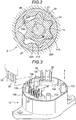
Fig. 3 is a perspective view of a motor housing; -
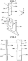
Fig. 4 is a perspective view of a tuning fork-shaped terminal and a conduction terminal; -
Fig. 5 is a view illustrating a side surface shape and a top surface shape of the conduction terminal; -
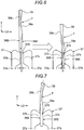
Fig. 6 is a view illustrating a state before and after conduction between the tuning fork-shaped terminal and the conduction terminal; -
Fig. 7 is a view illustrating bending of a flexible portion; and -
Fig. 8 is a view illustrating other embodiments in a list. - Embodiments disclosed here will be described below with reference to the drawings.
- As illustrated in
Fig. 1 , anoil pump 100 is constituted by connecting a motor housing 10 (an example of a first support), apump housing 20, and a control housing 30 (an example of a second support). - This
oil pump 100 is provided in, for example, a hybrid type vehicle or a vehicle in which idle stop control is performed, and enables supply of hydraulic pressure to a transmission in a situation where an engine (not shown) stops. - As illustrated in
Fig. 1 , theoil pump 100 houses anelectric motor 1 in aresin motor housing 10, houses apump portion 2 in ametal pump housing 20, and houses acontrol substrate 3 in aresin control housing 30. That is, theoil pump 100 has a structure in which the pump housing 20, themotor housing 10, and thecontrol housing 30 are stacked in this order. - In this
oil pump 100, adrive shaft 11 driven and rotated by a driving force of theelectric motor 1 is disposed in a region extending from themotor housing 10 to thepump housing 20, and thepump portion 2 is driven by the driving force of thedrive shaft 11. - The
pump housing 20 is provided with asuction port 27P and adischarge port 28P. By driving thepump portion 2 with the driving force of theelectric motor 1, oil is sucked from thesuction port 27P and oil is discharged from thedischarge port 28P. - For example, the
oil pump 100 is provided in the vehicle in such a manner that a part of thecontrol housing 30 is supported by a shift control case of the vehicle. Motor portion, Pump portion, and Drive shaft - As illustrated in
Fig. 1 , theelectric motor 1 includes adrive shaft 11 rotatably supported coaxially with a driving axis X, amotor rotor 12 fixed to one shaft end of thedrive shaft 11, and astator 13 disposed in a region surrounding themotor rotor 12. - The
motor rotor 12 includes a back yoke and a plurality of permanent magnets, and is disposed in amotor space 10S. Acoil 14 is wound around a stator core constituting thestator 13 and is inserted into themotor housing 10. Although thiselectric motor 1 is configured as a three-phase brushless DC motor, it may be configured as an induction motor or a three-phase motor. - As illustrated in
Fig. 1 andFig. 2 , thepump portion 2 is configured by housing aninner rotor 21 driven by thedrive shaft 11 and anouter rotor 22 as a pump rotor in apump space 24. Thepump portion 2 is configured in an internal gear type in which a part of anexternal tooth portion 21A of theinner rotor 21 and aninternal tooth portion 22A of theouter rotor 22 mesh with each other. - As illustrated in
Fig. 1 , thepump housing 20 is configured by stacking afirst housing 20A in which thepump space 24 is formed, asecond housing 20B connected to thefirst housing 20A, and a plate 20C connected to the outer surface side of thesecond housing 20B, and these are connected to each other by a connectingbolt 23a. Further, thepump housing 20 thus connected is fastened to themotor housing 10 by a fasteningbolt 23b. - A
pump space 24 is formed in thefirst housing 20A, and a first insertion hole portion 25 having a through hole shape into which thedrive shaft 11 of thedrive shaft 11 is inserted is formed. A secondinsertion hole portion 26 functioning as a bearing hole portion is formed in thesecond housing 20B. Asuction flow path 27 communicating with the negative pressure side of thepump space 24 and adischarge flow path 28 communicating with the high pressure side of thepump space 24 are formed in thesecond housing 20B. - In a plate 20C, the
suction port 27P in the form of a through hole is formed at a position communicating with thesuction flow path 27, and adischarge port 28P in the form of a through hole is formed at a position communicating with thedischarge flow path 28. - In the
oil pump 100, as illustrated inFig. 2 , theinner rotor 21 rotates integrally with thedrive shaft 11 as theelectric motor 1 rotates. In conjunction with this rotation of theouter rotor 22, the negative pressure acts on thesuction flow path 27, oil is sucked from thesuction port 27P to thesuction flow path 27, and the oil pressurized by thepump portion 2 is discharged from thedischarge flow path 28 to thedischarge port 28P. - As illustrated in
Fig. 1 , thecontrol housing 30 is formed in a casing shape to be joined to a joining end portion of themotor housing 10 on the opposite side to thepump housing 20 by a technique of welding or the like, and thecontrol substrate 3 described above is housed in aninner space 30S of thecontrol housing 30. Note that, theinner space 30S is a space including not only a space inside thecontrol housing 30 but also a recessed portion formed at the end portion of themotor housing 10. - The
control housing 30 is formed with a bulgingportion 31 which bulges in a direction away from themotor housing 10. Aflange portion 32 is integrally formed on the proximal end side (the lower side inFig. 1 ) of the bulgingportion 31, and aconnector portion 33 is integrally formed with a projecting portion (the upper end portion inFig. 1 ) in the direction in which the bulgingportion 31 bulges. - As illustrated in
Fig. 1 andFig. 3 , acylindrical wall portion 10a is integrally formed along the outer periphery of themotor housing 10 at a portion of themotor housing 10 on the opposite side to thecontrol housing 30. Theflange portion 32 is joined to the end face of thecylindrical wall portion 10a by thermal fusion bonding. An adhesive may be used as a bonding form, and bonding may be performed by fastening a screw or the like. - In the region surrounded by the
cylindrical wall portion 10a, a plurality (four in this embodiment) ofsubstrate support portions 10b are formed to protrude from themotor housing 10, and thecontrol substrate 3 is fixed to three of the foursubstrate support portions 10b by screws. A positioning protrusion of thecontrol substrate 3 is formed on the remaining one of thesubstrate support portions 10b. A groove-shaped engagement recessedportion 10c is formed at a plurality of positions on the inner periphery of thecylindrical wall portion 10a, and anengagement protrusion 34 engageable with the engagement recessedportion 10c is formed in thecontrol housing 30. - With such an engagement configuration provided, the motor housing 10 (an example of the first support) and the control housing 30 (an example of the second support) are relatively moved in the proximity direction along the movement direction T (the direction parallel with the driving axis X) as illustrated in
Fig. 3 , and therefore, the correspondingengagement protrusion 34 are brought into engagement with a plurality ofengagement protrusions 34, so that themotor housing 10 and thecontrol housing 30 have an appropriate positional relationship. - As illustrated in
Fig. 3 , threecoil terminals 35 conducted to thecoil 14 are formed so as to protrude from themotor housing 10. Further, in theinner space 30S, in a form supported by themotor housing 10, the plurality (four in the embodiment) of conductingshaft bodies 36 and the plurality (four in the embodiment) tuning fork-shapedterminals 37 are supported by themotor housing 10 in a positional relationship of being arranged in parallel. - Note that, the conducting
shaft body 36 and the tuning fork-shapedterminal 37 are integrally formed by pressing a good conductor such as a copper alloy. Also, it is also possible to use a steel plate for the tuning fork-shapedterminal 37. A pair ofcontact conduction portions 37b of the tuning fork-shapedterminal 37 is subjected to a surface treatment for performing gold plating, tin plating or the like (refer toFig. 4 ). - In the
control substrate 3, printed wiring is formed on the front surface, and control elements conducted to these are mounted. Three through holes into which the threecoil terminals 35 are inserted and four through holes into which the four conductingshaft bodies 36 are inserted are formed on thecontrol substrate 3. With this configuration, threecoil terminals 35 and four conductingshaft bodies 36 are connected by solder in a state where thecontrol substrate 3 is supported by thesubstrate support portion 10b while being inserted into the through holes. - Four
connector terminals 33a are provided inside theconnector portion 33, and four conduction terminals 38 (an example of plate-shaped terminals) individually conducted to theconnection terminals 33a are provided inside thecontrol housing 30. These are specific configurations of the electrical connection structure that reaches the electrically conductive state, and theconduction terminal 38 is made of a good conductor such as a copper alloy as described above, and is fit into a slit-shapedspace 37S of the tuning fork-shapedterminal 37 to which aconduction region 38S at the end position of theconduction terminal 38 corresponds. With this, the tuning fork-shapedterminal 37 and theconduction terminal 38 reach a conductive state. - With the electrical connection structure provided, when connecting the
pump housing 20 to themotor housing 10, in a state where the above-describedengagement protrusion 34 is engaged with the engagement recessedportion 10c, fourconduction terminal 38 are fitted into corresponding tuning-fork shapedterminals 37 by an operation of bringing them close to each other along the movement direction T as illustrated inFig. 4 . - Since the four conducting
shaft bodies 36 to which each of the four tuning fork-shapedterminals 37 are conducted are conducted to the printed wiring of thecontrol substrate 3, the electric power supplied from theconnector portion 33 is supplied to the threecoil terminals 35 via thecontrol substrate 3 to realize control of theelectric motor 1. - As illustrated in
Fig. 3 to Fig. 5 , the tuning-fork-shapedterminal 37 has an arm-shapedportion 37a having a forked shape, and has acontact conduction portion 37b protruding in the proximity direction at a distal end portion of each arm-shapedportion 37a. In addition, the slit-shapedspace 37S is formed between the pair of thecontact conduction portions 37b, and a region of theconduction terminal 38 which is interposed (fitted) by the pair ofcontact conduction portions 37b corresponds to theconduction region 38S. By chamfering a corner portion of the protruding end of theconduction region 38S, the arm-shapedportion 37a is easily fit into thecontact conduction portion 37b. - The tuning fork-shaped
terminal 37 is supported in a position fixed state with respect to themotor housing 10 as a first support and theconduction terminal 38 is supported in a position fixed state with respect to thecontrol housing 30 as a second support. - Accordingly, in a case where the positional relationship between the tuning fork-shaped
terminal 37 and theconduction terminal 38 is not appropriate due to a manufacturing error or the like, it is conceived that the tuning fork-shapedterminal 37 and theconduction terminal 38 do not fit appropriately when themotor housing 10 and thecontrol housing 30 are brought close to each other along the movement direction T in a state where theengagement protrusion 34 is engaged with the engagement recessedportion 10c. - Here, as illustrated in
Fig. 4 , the width direction (plate thickness direction of the tuning fork-shaped terminal 37) of theconduction terminal 38 is referred to as a first direction U1, the thickness direction of the conduction terminal 38 (width direction of the tuning fork-shaped terminal 37) is referred to as a second direction U2, and the positional relationship at the time of fitting theconduction terminal 38 and the tuning fork-shapedterminal 37 will be described. Note that, the first direction U1, the second direction U2, and the movement direction T are orthogonal to each other. - That is, even if the
conduction terminal 38 and the tuning fork-shapedterminal 37 are slightly shifted in the first direction U1 relative to each other based on the proper positional relationship, a position of theconduction terminal 38 fitted to a pair ofcontact conduction portions 37b of the tuning fork-shapedterminal 37 is displaced along the first direction U1 (in a direction orthogonal to the plate surface of the tuning fork shaped terminal 37), which does not cause inconvenience in fitting. - However, in a case where the
conduction terminal 38 and the tuning fork-shapedterminal 37 are slightly shifted in the second direction U2 based on the proper positional relationship, when theconduction terminal 38 is fitted to the tuning fork-shapedterminal 37, theconduction terminal 38 strongly contacts one of the pair ofcontact conduction portions 37b of the terminal 37. This contact expands the space between the arm-shapedportions 37a and leads to an inappropriate conducting state where only one of thecontact conduction portions 37b contacts theconduction terminal 38. - In order to solve this inconvenience, a thin-walled flexible portion F that allows deformation in a form in which the
conduction terminal 38 is bent is formed on the proximal end side (the upper side inFig. 4 ) from theconduction region 38S. As illustrated in the left side ofFig. 4 and Fig. 5 , the flexible portion F has a recessedportion 38a having a cross-sectional shape of a circular arc shape or an arc shape as viewed in a direction along the first direction U1, and in the right side ofFig. 5 , the flexible portion F has a pair ofnarrow portions 38b narrowing the portion corresponding to the area where the recessedportion 38a is formed as viewed in a direction along the second direction U2. - Due to this structure, as illustrated in
Fig. 6 , in the connecting operation in a state where a center line in the thickness direction of theconduction terminal 38 is offset by an offset amount Q based one the center lines of the pair ofcontact conduction portions 37b of the tuning fork-shaped terminal 37 (a state where positional relationship shifted in the direction of the second direction U2), the connection is allowed in a state where theconduction terminal 38 is deformed by bending of the flexible portion F. - That is, in this connection operation, when motor housing 10 (first support) and the control housing 30 (second support) are brought close to each other along the movement direction T so as to be connected to each other, as illustrated in the left side of
Fig. 6 , theconduction region 38S of the conduction terminal 38 (plate-shaped terminal) is inserted into the slit-shapedspace 37S of the tuning fork-shapedterminal 37. In this inserted state, when themotor housing 10 and thecontrol housing 30 are brought further closer to each other, a force acts between the tuning fork-shapedterminal 37 and theconduction terminal 38, and due to the action of this force, theconduction terminal 38 is deformed in the flexible portion F by bending as illustrated in the right side ofFig. 6 . - In the right side of
Fig. 6 , a state where the tuning fork-shapedterminal 37 and theconduction terminal 38 reach a connection position is illustrated, and as illustrated inFig. 6 , as theconduction terminal 38 is bent in the flexible portion F, the phenomenon that theconduction terminal 38 strongly contacts only one of the pair ofcontact conduction portions 37b is suppressed while the center in the thickness direction at a base end portion of theconduction terminal 38 is offset from the center of the pair ofcontact conduction portions 37b of the tuning fork-shapedterminal 37, so that there is no enlargement of the space between the pair of arm-shapedportions 37a, and an excellent conduction state in which theconduction region 38S of theconduction terminal 38 is equally interposed by the inner surfaces of the pair ofcontact conduction portions 37b is realized. - In this configuration, since the recessed
portion 38a has a cross section having a circular arc shape or an arc shape, in the case where theconduction terminal 38 is bent in the flexible portion F, smooth deformation is realized without locally concentrating the stress. In addition, with the pair ofnarrow portions 38b formed, it is possible to make excellent deformation without reducing the thickness of the thin portion of the flexible portion F to a small value. - The flexible portion F is formed on the proximal end side from the position in contact with the
conduction terminal 38 with respect to thecontact conduction portion 37b, and thus, for example, as compared with a portion in which a part of the flexible portion F overlaps thecontact conduction portion 37b, it is possible to lead the deformation of the flexible portion F to an excellent conduction state. - Further, it is also supposed that the center line tilts in the thickness direction of the
conduction terminal 38 with respect to the center line of the pair ofcontact conduction portions 37b of the tuning fork-shapedterminal 37. In such a case, in a state where the tuning fork-shapedterminal 37 and theconduction terminal 38 reach the connection position, as illustrated inFig. 7 , theconduction terminal 38 is bent so as to be curved in the flexible portion F, thereby an excellent conduction state in which theconduction region 38S of theconduction terminal 38 is equally interposed by the inner surfaces of the pair ofcontact conduction portions 37b is realized. - The present invention may be configured in the following manner besides the above-described embodiments (those having the same functions as those in the embodiment are denoted by the same reference numerals as in the embodiments).
- (a) As illustrated in column I of
Fig. 8 , similar to the embodiment, a plurality of the recessedportions 38a which are thin in the plate thickness direction and whose cross-sectional shape is that of an arc, in particular a circular arc are continuously arranged on one surface of the conduction terminal 38 (two in embodiment a) in the extension direction of theconduction terminal 38 so as to form the flexible portion F. This configuration enables excellent bending without reducing the thickness of the flexible portion F. In this embodiment (a), the flexible portion F can be configured to include three or more recessedportions 38a, and the flexible portion F may be configured to be narrow. - (b) As illustrated in column II in
Fig. 8 , similar to the embodiment, a plurality of the recessedportions 38a whose cross-sectional shape is that of an arc, in particular a circular arc are arranged at a position where both surfaces of theconduction terminal 38 overlap with each other in the plate thickness direction so as to form the flexible portion F. In this embodiment (b), two pairs of recessedportions 38a overlapping with each other in the plate thickness direction are arranged in the extension direction of theconduction terminal 38. This configuration enables excellent bending. In this embodiment (b), the flexible portion F may be configured to be narrow. Further, the number of the recessedportions 38a may be one. - (c) As illustrated in column III of
Fig. 8 , as the flexible portion F, a single recessedportion 38a including a flatbottom surface portion 38p that is parallel to the plate surface of theconduction terminal 38 and a pair of side surface portions 39q continuous with thebottom surface portion 38p is configured. With such a cross-sectional shape, for example, it is possible to adjust the length of thebottom surface portion 38p in the projecting direction of theconduction terminal 38 while maintaining the thickness of theconduction terminal 38 of thebottom surface portion 38p at a constant value. In this embodiment (c), the flexible portion F may be configured to be narrow. Further, a plurality of sets of the recessedportion 38a may be provided. - (d) As illustrated in column IV of
Fig. 8 , the recessedportion 38a of embodiment (c) is disposed on both sides of theconduction terminal 38 so as to form the flexible portion F. In this embodiment (d), the pair of recessedportions 38a are arranged at positions where the recessedportions 38a overlap with each other, but may be arranged to deviate somewhat in the projecting direction. From the configuration of this embodiment (d), bending is performed in a form in which thebottom surface portion 38p is curved on average. In this embodiment (d), the flexible portion F may be configured to be narrow. Further, a plurality of sets of the recessedportion 38a may be provided. - (e) As illustrated in column V of
Fig. 8 , the flexible portion F is formed in theconduction terminal 38 by setting the thickness of a distal end portion smaller than the base end portion of theconduction terminal 38. In this embodiment (e), a thin wall portion 38T which is thinned by cutting or pressing is formed on one surface of theconduction terminal 38. A central region of theconduction terminal 38 in this thin portion 38T is the flexible portion F, and theconduction region 38S is formed on both surfaces of the distal end portion. In the configuration of this embodiment (e), it is possible to bend in a region where the projecting direction of theconduction terminal 38 is long. In this embodiment (e), the flexible portion F may be configured to be narrow. - (f) As illustrated in column VI of
Fig. 8 , a plurality ofgroove portions 38r are formed on at least one surface in the thickness direction of theconduction terminal 38 to cover the entire width of theconduction terminal 38 so as to form the flexible portion F. In this embodiment (f), a plurality ofgroove portions 38r having different groove depths are formed on both surfaces of theconduction terminal 38, and the bending of theconduction terminal 38 at each of the plurality ofgroove portions 38r can make the bending enlarged overall. In this embodiment (f), the flexible portion F may be configured to be narrow. - (g) As illustrated in column VII of
Fig. 8 , similar to the embodiment, the flexible portion F is constituted by arranging the recessedportions 38a whose cross-sectional shape is that of an arc, in particular a circular arc at positions shifted from each other in the extension direction of theconduction terminal 38 on both surfaces of theconduction terminal 38. This configuration enables excellent bending without reducing the thickness of the flexible portion F. In the configuration of this embodiment (g), the flexible portion F can be configured to include three or more recessedportions 38a. In this embodiment (g), the flexible portion F may be configured to be narrow. - (h) Instead of an electrical connection structure that is in a conductive state inside the housing as in the embodiment, for example, the tuning fork-shaped
terminal 37 is supported on one of a pair of fitting members configured so as to be fitted and separated, and theconduction terminal 38 is provided on the other side, thereby constituting a connector. In this configuration, one of the pair of fitting members is afirst support 10 and the other is asecond support 30. In addition, this is applied to the electrical connection structure other than the electrical connection structure described in the embodiment. - The present invention can be used for an electrical connection structure that reaches a conductive state by fitting a plate-shaped terminal in a slit-shaped space of a tuning fork-shaped terminal.
- The principles, preferred embodiment and mode of operation of the present invention have been described in the foregoing specification. However, the invention which is intended to be protected is not to be construed as limited to the particular embodiments disclosed. Further, the embodiments described herein are to be regarded as illustrative rather than restrictive. Variations and changes may be made by others, and equivalents employed, without departing from the spirit of the present invention. Accordingly, it is expressly intended that all such variations, changes and equivalents which fall within the spirit and scope of the present invention as defined in the claims, be embraced thereby.
Claims (5)
- An electrical connection structure, comprising:a tuning fork-shaped terminal (37) having a slit-shaped space (37S) formed at an end portion;a first support (10) that supports the tuning fork-shaped terminal (37);a plate-shaped terminal (38) having a conduction region (38S) formed at an end portion; anda second support (30) that supports the plate-shaped terminal (38),wherein the electrical connection structure has a structure in which the conduction region (38S) of the plate-shaped terminal (38) is fitted into the slit-shaped space (37S) of the tuning fork-shaped terminal (37) by connecting the first support (10) and the second support (30), and thereby the tuning fork-shaped terminal (37) and the plate-shaped terminal (38) reach an electrical conduction state, andthe plate-shaped terminal (38) includes a thinned flexible portion (F) that allows deformation due to bending in a plate thickness direction.
- The electrical connection structure according to claim 1,
wherein the flexible portion (F) is formed as a recessed portion (38a) having a cross-sectional shape which is an arc shape at a center portion in an extension direction of the plate-shaped terminal (38). - The electrical connection structure according to claim 1,
wherein the flexible portion (F) is formed as a recessed portion (38a) having a cross-sectional shape which is a circular arc shape at a center portion in an extension direction of the plate-shaped terminal (38). - The electrical connection structure according to any one of claims 1 to 3,
wherein the tuning fork-shaped terminal (37) has a pair of contact conduction portions (37b) interposing the conduction region (38S) of the plate-shaped terminal (38) fitted into the slit-shaped space (37), and
the flexible portion (F) is disposed on a proximal end side of the plate-shaped terminal (38) with respect to a contact position at which the conduction region (38S) of the plate-shaped terminal (38) contacts the contact conduction portion (37b). - The electrical connection structure according to any one of claims 1 to 4,
wherein the flexible portion (F) has a reduced width in a width direction (U1) of the plate-shaped terminal (38).
Applications Claiming Priority (1)
| Application Number | Priority Date | Filing Date | Title |
|---|---|---|---|
| JP2017204399A JP2019079641A (en) | 2017-10-23 | 2017-10-23 | Electrical connection structure |
Publications (1)
| Publication Number | Publication Date |
|---|---|
| EP3474385A1 true EP3474385A1 (en) | 2019-04-24 |
Family
ID=63965305
Family Applications (1)
| Application Number | Title | Priority Date | Filing Date |
|---|---|---|---|
| EP18201895.2A Withdrawn EP3474385A1 (en) | 2017-10-23 | 2018-10-23 | Electrical connection structure |
Country Status (4)
| Country | Link |
|---|---|
| US (1) | US10490924B2 (en) |
| EP (1) | EP3474385A1 (en) |
| JP (1) | JP2019079641A (en) |
| CN (1) | CN109698420A (en) |
Families Citing this family (1)
| Publication number | Priority date | Publication date | Assignee | Title |
|---|---|---|---|---|
| USD871346S1 (en) * | 2018-07-08 | 2019-12-31 | Every Industry Llc | Explosion-proof junction box |
Citations (5)
| Publication number | Priority date | Publication date | Assignee | Title |
|---|---|---|---|---|
| JP2003250213A (en) | 2002-02-26 | 2003-09-05 | Fujikura Ltd | Electric connection structure and electric connection box using the same |
| US20140141631A1 (en) * | 2012-11-16 | 2014-05-22 | Delta Electronics (Shanghai) Co., Ltd. | Package module, package terminal and manufacturing method thereof |
| CN204680787U (en) * | 2015-05-28 | 2015-09-30 | 欧度(上海)连接器制造有限公司 | Connector |
| US9184524B2 (en) * | 2012-08-28 | 2015-11-10 | Denso Corporation | Solenoid |
| KR20160110717A (en) * | 2015-03-11 | 2016-09-22 | 주식회사 듀링플러스 | Elastic signal pin |
Family Cites Families (39)
| Publication number | Priority date | Publication date | Assignee | Title |
|---|---|---|---|---|
| US3545080A (en) * | 1967-05-16 | 1970-12-08 | Amp Inc | Method of making resilient pins |
| US4030792A (en) * | 1976-03-01 | 1977-06-21 | Fabri-Tek Incorporated | Tuning fork connector |
| DE3906207A1 (en) * | 1989-02-28 | 1990-09-06 | Daut & Rietz Trw | FLAT CONTACT SPRING FOR CONNECTORS OF ELECTRICAL CONNECTORS |
| US5004426A (en) * | 1989-09-19 | 1991-04-02 | Teradyne, Inc. | Electrically connecting |
| US5147218A (en) * | 1991-04-12 | 1992-09-15 | Minnesota Mining And Manufacturing Company | Pluggable modular splicing connector and bridging adapter |
| US5273442A (en) * | 1992-12-24 | 1993-12-28 | The Whitaker Corporation | Modular chip carrier socket |
| JP2734994B2 (en) * | 1994-07-20 | 1998-04-02 | 住友電装株式会社 | Male terminal fitting |
| JP3177144B2 (en) * | 1996-02-14 | 2001-06-18 | 矢崎総業株式会社 | Male terminal |
| JP3106957B2 (en) * | 1996-05-27 | 2000-11-06 | 住友電装株式会社 | Board connector |
| JP3560200B2 (en) * | 1996-06-18 | 2004-09-02 | 矢崎総業株式会社 | Connection terminal mounting structure |
| US5957734A (en) * | 1998-01-21 | 1999-09-28 | General Motors Corporation | Tuning fork inline connection system |
| US6062916A (en) * | 1998-07-14 | 2000-05-16 | General Motors Corporation | Printed circuit board with pass through bussed terminal system for a bussed electrical distribution center |
| US6099338A (en) * | 1998-11-09 | 2000-08-08 | Huang; Chyong-Yen | Securing means for blades of electrical plug |
| US6254440B1 (en) * | 1998-12-07 | 2001-07-03 | Hon Hai Precision Ind. Co., Ltd. | Terminal having contact portion with reduced thickness |
| JP3354902B2 (en) * | 1999-06-25 | 2002-12-09 | エヌイーシートーキン株式会社 | Connector contact and method of manufacturing the same |
| US6406338B1 (en) * | 1999-07-08 | 2002-06-18 | Yazaki Corporation | Board terminal and method of producing same |
| JP3480708B2 (en) * | 2000-03-15 | 2003-12-22 | 住友電装株式会社 | Male terminal fitting |
| JP2002100443A (en) * | 2000-09-20 | 2002-04-05 | Auto Network Gijutsu Kenkyusho:Kk | Board connector |
| DE20110131U1 (en) * | 2001-06-19 | 2002-10-24 | Robert Bosch Gmbh, 70469 Stuttgart | Electrical connector |
| JP2003036910A (en) * | 2001-07-19 | 2003-02-07 | Yazaki Corp | Connector terminal |
| JP3866631B2 (en) * | 2002-07-30 | 2007-01-10 | 三菱電線工業株式会社 | Male rod-shaped connection terminal and method for manufacturing the same |
| US6997727B1 (en) * | 2003-03-14 | 2006-02-14 | Zierick Manufacturing Corp | Compliant surface mount electrical contacts for circuit boards and method of making and using same |
| JP4100282B2 (en) | 2003-08-08 | 2008-06-11 | 住友電装株式会社 | Electric junction box with slit width inspection part for tuning fork terminals |
| JP4348224B2 (en) | 2004-03-31 | 2009-10-21 | 株式会社オートネットワーク技術研究所 | Electrical junction box |
| JP2005312129A (en) * | 2004-04-19 | 2005-11-04 | Auto Network Gijutsu Kenkyusho:Kk | Electrical junction box |
| JP4361429B2 (en) * | 2004-06-29 | 2009-11-11 | 矢崎総業株式会社 | Direct connector mating structure |
| CN2833960Y (en) * | 2005-09-30 | 2006-11-01 | 番禺得意精密电子工业有限公司 | Electric connector |
| CN2862428Y (en) * | 2005-09-30 | 2007-01-24 | 番禺得意精密电子工业有限公司 | Electric connector |
| DE102006001876A1 (en) * | 2006-01-13 | 2007-11-08 | Siemens Ag | Component with an electrical printed circuit board |
| US20080188112A1 (en) * | 2007-02-06 | 2008-08-07 | Lotes Co., Ltd | Electrical connector |
| CN201207462Y (en) * | 2008-03-28 | 2009-03-11 | 众鸣精密工业(深圳)有限公司 | Electric connector |
| EP2413435B1 (en) * | 2009-03-25 | 2018-05-16 | Yazaki Corporation | Connector |
| WO2012023038A2 (en) * | 2010-08-20 | 2012-02-23 | Fci Automotive Holding | Electrical male terminal |
| JP6007146B2 (en) * | 2012-04-27 | 2016-10-12 | 第一電子工業株式会社 | connector |
| JP5454646B1 (en) * | 2012-09-25 | 2014-03-26 | 第一精工株式会社 | Electrical connector |
| JP5700026B2 (en) * | 2012-11-28 | 2015-04-15 | 株式会社デンソー | Terminal equipment for electrical equipment |
| JP6198069B2 (en) | 2014-12-03 | 2017-09-20 | 住友電装株式会社 | Board connector |
| CN204597029U (en) * | 2015-03-31 | 2015-08-26 | 谢子聪 | A kind of electric automobile change arrangements of electric connection |
| CN106450867B (en) * | 2016-10-12 | 2019-03-15 | 维尔斯电子(昆山)有限公司 | A kind of attaching plug and socket |
-
2017
- 2017-10-23 JP JP2017204399A patent/JP2019079641A/en active Pending
-
2018
- 2018-10-19 CN CN201811222103.7A patent/CN109698420A/en active Pending
- 2018-10-22 US US16/166,652 patent/US10490924B2/en not_active Expired - Fee Related
- 2018-10-23 EP EP18201895.2A patent/EP3474385A1/en not_active Withdrawn
Patent Citations (5)
| Publication number | Priority date | Publication date | Assignee | Title |
|---|---|---|---|---|
| JP2003250213A (en) | 2002-02-26 | 2003-09-05 | Fujikura Ltd | Electric connection structure and electric connection box using the same |
| US9184524B2 (en) * | 2012-08-28 | 2015-11-10 | Denso Corporation | Solenoid |
| US20140141631A1 (en) * | 2012-11-16 | 2014-05-22 | Delta Electronics (Shanghai) Co., Ltd. | Package module, package terminal and manufacturing method thereof |
| KR20160110717A (en) * | 2015-03-11 | 2016-09-22 | 주식회사 듀링플러스 | Elastic signal pin |
| CN204680787U (en) * | 2015-05-28 | 2015-09-30 | 欧度(上海)连接器制造有限公司 | Connector |
Also Published As
| Publication number | Publication date |
|---|---|
| US20190123466A1 (en) | 2019-04-25 |
| US10490924B2 (en) | 2019-11-26 |
| JP2019079641A (en) | 2019-05-23 |
| CN109698420A (en) | 2019-04-30 |
Similar Documents
| Publication | Publication Date | Title |
|---|---|---|
| JP6248984B2 (en) | Drive device | |
| US10435060B2 (en) | Electronic control device | |
| JP4353951B2 (en) | Electric power steering device | |
| JP2018071499A (en) | Electric pump | |
| KR101834092B1 (en) | Lead frame, electronic control device using lead frame, and lead-frame mounting method | |
| JP6500952B2 (en) | Electric power steering device | |
| US11462969B2 (en) | Rotary apparatus | |
| JP6394533B2 (en) | Mechanical and electrical integrated device | |
| US10490924B2 (en) | Electrical connection structure including tuning fork-shaped terminal | |
| JP3972598B2 (en) | Brushless motor and its terminal structure | |
| TW201108571A (en) | Motor | |
| JP7198674B2 (en) | case mold type capacitor | |
| JP2022061246A (en) | Motor unit and electric pump with the same | |
| US20080303374A1 (en) | Motor with rotor shaft and rotor magnet | |
| US10873235B2 (en) | DC motor with a positive temperature coefficient thermistor | |
| JP2017152389A (en) | Electronic control unit | |
| US12068653B2 (en) | Coil, stator member, stator, and motor | |
| US6836050B2 (en) | Terminal structures for motor with brush to connect motor to external circuit | |
| JPH09331641A (en) | Rotating electric machine | |
| US20170201144A1 (en) | Brushless motor | |
| JP2017033875A (en) | Electromechanical device | |
| US20080297009A1 (en) | Stator member and motor | |
| JPH11299165A (en) | Miniature dc motor | |
| JP2017033877A (en) | Mechanical and electrical integrated device | |
| JP2017033878A (en) | Mechatronic device |
Legal Events
| Date | Code | Title | Description |
|---|---|---|---|
| PUAI | Public reference made under article 153(3) epc to a published international application that has entered the european phase |
Free format text: ORIGINAL CODE: 0009012 |
|
| STAA | Information on the status of an ep patent application or granted ep patent |
Free format text: STATUS: THE APPLICATION HAS BEEN PUBLISHED |
|
| AK | Designated contracting states |
Kind code of ref document: A1 Designated state(s): AL AT BE BG CH CY CZ DE DK EE ES FI FR GB GR HR HU IE IS IT LI LT LU LV MC MK MT NL NO PL PT RO RS SE SI SK SM TR |
|
| AX | Request for extension of the european patent |
Extension state: BA ME |
|
| STAA | Information on the status of an ep patent application or granted ep patent |
Free format text: STATUS: THE APPLICATION IS DEEMED TO BE WITHDRAWN |
|
| 18D | Application deemed to be withdrawn |
Effective date: 20191025 |