WO2010110032A1 - Connector - Google Patents
Connector Download PDFInfo
- Publication number
- WO2010110032A1 WO2010110032A1 PCT/JP2010/053625 JP2010053625W WO2010110032A1 WO 2010110032 A1 WO2010110032 A1 WO 2010110032A1 JP 2010053625 W JP2010053625 W JP 2010053625W WO 2010110032 A1 WO2010110032 A1 WO 2010110032A1
- Authority
- WO
- WIPO (PCT)
- Prior art keywords
- connector
- inner housing
- housing
- electrical connection
- terminal
- Prior art date
Links
Images


Classifications
-
- H—ELECTRICITY
- H01—ELECTRIC ELEMENTS
- H01R—ELECTRICALLY-CONDUCTIVE CONNECTIONS; STRUCTURAL ASSOCIATIONS OF A PLURALITY OF MUTUALLY-INSULATED ELECTRICAL CONNECTING ELEMENTS; COUPLING DEVICES; CURRENT COLLECTORS
- H01R13/00—Details of coupling devices of the kinds covered by groups H01R12/70 or H01R24/00 - H01R33/00
- H01R13/62—Means for facilitating engagement or disengagement of coupling parts or for holding them in engagement
- H01R13/629—Additional means for facilitating engagement or disengagement of coupling parts, e.g. aligning or guiding means, levers, gas pressure electrical locking indicators, manufacturing tolerances
- H01R13/631—Additional means for facilitating engagement or disengagement of coupling parts, e.g. aligning or guiding means, levers, gas pressure electrical locking indicators, manufacturing tolerances for engagement only
- H01R13/6315—Additional means for facilitating engagement or disengagement of coupling parts, e.g. aligning or guiding means, levers, gas pressure electrical locking indicators, manufacturing tolerances for engagement only allowing relative movement between coupling parts, e.g. floating connection
-
- H—ELECTRICITY
- H01—ELECTRIC ELEMENTS
- H01R—ELECTRICALLY-CONDUCTIVE CONNECTIONS; STRUCTURAL ASSOCIATIONS OF A PLURALITY OF MUTUALLY-INSULATED ELECTRICAL CONNECTING ELEMENTS; COUPLING DEVICES; CURRENT COLLECTORS
- H01R13/00—Details of coupling devices of the kinds covered by groups H01R12/70 or H01R24/00 - H01R33/00
- H01R13/02—Contact members
- H01R13/04—Pins or blades for co-operation with sockets
- H01R13/05—Resilient pins or blades
-
- H—ELECTRICITY
- H01—ELECTRIC ELEMENTS
- H01R—ELECTRICALLY-CONDUCTIVE CONNECTIONS; STRUCTURAL ASSOCIATIONS OF A PLURALITY OF MUTUALLY-INSULATED ELECTRICAL CONNECTING ELEMENTS; COUPLING DEVICES; CURRENT COLLECTORS
- H01R13/00—Details of coupling devices of the kinds covered by groups H01R12/70 or H01R24/00 - H01R33/00
- H01R13/46—Bases; Cases
- H01R13/514—Bases; Cases composed as a modular blocks or assembly, i.e. composed of co-operating parts provided with contact members or holding contact members between them
Definitions
- the present invention relates to a connector including a terminal metal fitting, an inner housing that accommodates the terminal metal fitting, and an outer housing that accommodates the terminal metal fitting and the inner housing.
- the wire harness is composed of a plurality of electric wires and a plurality of connectors attached to the ends of these electric wires.
- the connector is composed of a terminal fitting and a housing that accommodates the terminal fitting. And each connector of this wire harness is each fitted by each connector fixed to the case of each electronic device, etc., and these electronic devices are electrically connected.
- the terminal metal fitting of the connector and the terminal metal fitting of the mating connector may be misaligned and may not be mated with the mating connector.
- a terminal fitting capable of absorbing such a positional deviation from the counterpart terminal fitting for example, there is a terminal fitting disclosed in Patent Document 1.
- a connector capable of absorbing such a positional deviation from the terminal fitting of the mating connector there is a connector disclosed in Patent Document 2, for example.
- the terminal fitting shown in Patent Document 1 includes a first female terminal portion into which a first male terminal as a “mating terminal fitting” is inserted, and a second female terminal as a “mating terminal fitting”.
- a second female terminal portion into which a male terminal is inserted, and a connecting portion that connects the first female terminal portion and the second female terminal portion are provided.
- the connecting portion is provided with a buffer portion that is narrower or thinner than other portions of the connecting portion.
- the connector shown in Patent Document 2 includes a terminal fitting attached to an end of an electric wire, an inner housing that houses the terminal fitting, an outer housing that movably accommodates the inner housing that houses the terminal fitting, A spring washer disposed between the inner housing and the inner bottom surface of the outer housing and biasing the inner housing toward the mating connector.
- a stopper is provided on the inner side surface of the outer housing to prevent the inner housing from coming out of the outer housing.
- the terminal fitting shown in Patent Document 1 described above can move the first female terminal portion or the second female terminal portion only in one direction, that is, only in the thickness direction of the buffer portion.
- the positional deviation between the terminal fittings generated in the width direction of the buffer portion and the direction in which the first female terminal portion and the second female terminal portion are arranged cannot be absorbed.
- the connector disclosed in Patent Document 2 is provided with a stopper on the inner side surface of the outer housing for preventing the inner housing from coming out of the outer housing.
- this stopper is structured to be assembled to the outer housing after the inner housing is accommodated in the outer housing, the number of parts is increased in the connector, and the structure of the outer housing is also increased. There was a problem of becoming complicated. Further, in the connector, there is a problem that severe dimensional accuracy is required for the outer housing and the stopper, resulting in high cost.
- the connector disclosed in Patent Document 2 has a configuration in which the electric wire connected to the terminal fitting is drawn out of the outer housing through a through hole provided in the inner bottom surface of the outer housing.
- the wire is also largely tilted, which may affect the connection reliability between the wire and a member electrically connected to the wire. There was a problem.
- the present invention pays attention to the above-mentioned problems, and absorbs the positional deviation generated between the terminal fitting and the terminal fitting of the counterpart connector when mating with the counterpart connector, thereby securely It is a first object to provide a connector that can be fitted into the connector. In addition, the present invention absorbs misalignment in all directions between the terminal fitting and the terminal fitting of the mating connector when mating with the mating connector, thereby further securely mating with the mating connector. It is a second object to provide a connector that can be used. In addition, the present invention can absorb the positional deviation generated between the terminal fitting and the terminal fitting of the mating connector at the time of fitting with the mating connector, and can be securely fitted with the mating connector.
- a third object of the present invention is to provide a connector that can prevent breakage due to an impact when mated with a mating connector.
- the present invention can absorb the positional deviation generated between the terminal fitting and the terminal fitting of the mating connector at the time of fitting with the mating connector, and can be securely fitted with the mating connector.
- a fourth object of the present invention is to provide a connector with a simple configuration that can prevent damage due to an impact when mated with a mating connector and that has a small number of parts.
- the invention described in claim 1 is a connector including a terminal fitting, an inner housing, and an outer housing that accommodates the terminal fitting and the inner housing.
- the terminal fitting is housed and held in the inner housing and is electrically connected to the mating connector, and is disposed at a position farther from the mating connector than the first electrical connection portion.
- a second electrical connection portion and a connection made of a conductive material and having flexibility or flexibility, wherein the first electrical connection portion and the second electrical connection portion are movably connected to each other and electrically connected.
- a housing portion in which the inner housing housing the first electrical connection portion is movably accommodated in the outer housing, and the second electrical connection portion A fixed portion fixed a connector, characterized in that is provided.
- the invention described in claim 2 is characterized in that, in the invention described in claim 1, the connecting portion is formed of a braided wire. It is.
- the invention described in claim 3 is the invention described in claim 1, wherein the connecting portion is formed by pressing a metal plate, and the connection A ring-shaped first annular portion that is attached to the first electrical connection portion; an annular second annular portion that is attached to the second electrical connection portion; and one end that is connected to the first annular portion and the other end A plurality of arcuate portions formed in a band shape that is continuous with the second annular portion and bent between the first annular portion and the second annular portion in an arcuate manner in all directions.
- the first electrical connection portion and the second electrical connection portion are movably coupled in all directions by being elastically deformed.
- the invention described in claim 4 is characterized in that, in the invention described in claim 1, the connecting portion is constituted by a coil spring. It is.
- the invention described in claim 5 is the invention described in one of claims 1 to 4, wherein the invention is arranged between the fixed portion and the inner housing. And an urging member for urging the inner housing toward the mating connector.
- the invention described in claim 6 is the invention described in claim 5, wherein the biasing member is formed of a coil spring. Is.
- the invention described in claim 7 is the invention described in claim 5, wherein the urging member is formed in a cylindrical shape from rubber, and The connecting portion is positioned inside the biasing member.
- the invention described in claim 8 is the invention described in one of claims 1 to 7, wherein the invention is installed in the housing portion and houses the inner housing. It further comprises a cylindrical holder.
- the invention described in claim 9 is the invention described in claim 8, in which the holder is fitted in the accommodating portion in the fitting direction with the mating connector. It is attached so that it can move along the direction which cross
- the invention described in claim 10 is the invention described in claim 8 or 9, wherein the inner housing is attached to the holder on the inner surface of the housing portion.
- An urging portion that urges toward the side is provided.
- the invention described in claim 11 is the invention described in one of claims 8 to 10, wherein the inner housing is attached to the holder by the holder. A stopper is provided to prevent going out.
- the invention described in claim 12 is the invention described in one of claims 8 to 11, wherein the holder is made of a metal material. It is characterized by.
- the invention described in claim 13 is the invention described in claim 8 or 9, wherein the holder is formed by pressing a metal plate.
- the holder is formed in a cylindrical shape and accommodates the inner housing, and a part of the cylindrical portion is cut and raised and bent inside the cylindrical portion, and the inner housing is accommodated in the holder.
- An urging portion that urges toward an inner surface of the portion, and is formed by being bent from one end portion of the cylindrical portion and inside the cylindrical portion and toward the mating connector, and the fixing portion and the A second urging portion disposed between the inner housing and urging the inner housing toward the mating connector; and extending from the other end portion of the cylindrical portion, wherein the inner housing is connected to the cylindrical portion.
- the opening on the other end side A stopper that is formed by being bent so as to cover the end surface of the inner housing on the mating connector side after being inserted into the cylindrical portion, and prevents the inner housing from coming out of the accommodating portion. It is characterized by being provided.
- the invention described in claim 14 is the invention described in one of claims 8 to 13, wherein the first electrical connection portion is provided in the inner housing.
- An inner housing main body to be accommodated and an elastic arm that is connected to the outer surface of the inner housing main body and elastically contacts the inner surface of the holder are provided.
- the invention described in claim 15 is the invention described in one of claims 1 to 14, in which the inner housing is disposed in the housing portion in the entire housing. It is accommodated in such a way that it can move freely in the direction.
- the terminal fitting is accommodated and held in the inner housing and is electrically connected to the mating connector, than the first electrical connecting portion.
- a second electrical connecting portion disposed at a position away from the mating connector; and formed of a conductive material and having flexibility or flexibility; the first electrical connecting portion and the second electrical connecting portion; And a connecting portion electrically connected to each other and electrically connected to each other, and a housing portion in which the inner housing housing the first electrical connecting portion is movably accommodated in the outer housing, and And a fixing portion to which the second electrical connecting portion is fixed.
- the first electrical connecting portion is The a Na housing, to absorb the positional deviation between the first electrical connection portion and the terminal fitting of the mating connector is moved in the housing portion so as to be electrically connected. Further, even if the inner housing and the first electrical connection portion move in this way, the second electrical connection portion is fixed to the fixed portion and does not move. Therefore, the second electrical connection portion and the second electrical connection portion are not moved. It is possible to prevent the connection reliability with the member electrically connected to the electrical connection portion from being affected. In addition, when the first electrical connection portion moves in this manner, the connecting portion having flexibility or flexibility is deformed, and thus distortion occurs in the first electrical connection portion and the second electrical connection portion. Can be prevented.
- the connecting portion when vibration is applied to the connector, the connecting portion is deformed to absorb the vibration, which may affect the connection reliability between the terminal fitting and the terminal fitting of the mating connector. Can be prevented. Therefore, it is possible to provide a connector that can be securely fitted to the mating connector by absorbing a positional shift generated between the terminal fitting and the mating connector terminal fitting when mated with the mating connector. Can do.
- the connecting portion is formed of a braided wire, the connecting portion can be deformed in all directions, and therefore, when fitted with the mating connector.
- the connecting portion can absorb misalignment in all directions between the terminal fitting and the terminal fitting of the mating connector and can be more securely fitted to the mating connector.
- the connecting portion is formed by pressing a metal plate, and the connecting portion is an annular first annular portion attached to the first electrical connecting portion; An annular second annular portion attached to the second electrical connecting portion, and a first annular portion formed in a belt shape having one end connected to the first annular portion and the other end connected to the second annular portion. And a plurality of arcuate portions bent in an arcuate shape between the second annular portion and the second annular portion, and are formed to be elastically deformable in all directions. And the second electrical connection portion are movably coupled in all directions, so that when the mating connector is fitted, the displacement in all directions that occurs between the terminal fitting and the terminal fitting of the counterpart connector Can be more securely fitted to the mating connector. It is possible to provide a connector.
- the connecting portion is constituted by a coil spring, the connecting portion can be deformed in all directions, and therefore, when fitted with the mating connector.
- the connecting portion can absorb misalignment in all directions between the terminal fitting and the terminal fitting of the mating connector and can be more securely fitted to the mating connector.
- the invention described in claim 5 since it further includes a biasing member that is disposed between the fixed portion and the inner housing and biases the inner housing toward the mating connector.
- the inner housing When the mating connector collides with the inner housing, the inner housing is once moved to the fixed portion side and then pushed back to the mating connector side by the elastic restoring force of the biasing member.
- the inner housing can be prevented from violently colliding with and being damaged by the fixed portion.
- the biasing member elastically deforms to absorb the vibration, which affects connection reliability between the terminal fitting and the terminal fitting of the mating connector. Can be prevented.
- the misalignment between the terminal fitting and the mating connector's terminal fitting can be absorbed, and the mating connector can be securely fitted, and the mating connector It is possible to provide a connector that can prevent breakage due to an impact when mated with the connector.
- the biasing member is constituted by a coil spring, it is generated between the terminal metal fitting and the terminal metal fitting of the counterpart connector at the time of fitting with the counterpart connector. Therefore, it is possible to provide a connector that can absorb the misalignment and can be securely fitted to the mating connector, and can be prevented from being damaged by an impact when mating with the mating connector.
- the urging member is formed in a cylindrical shape with rubber, and the connecting portion is positioned inside the urging member, When mating, it absorbs the misalignment that occurs between the terminal fitting and the terminal fitting of the mating connector so that it can be securely mated with the mating connector and when mating with the mating connector. It is possible to provide a connector that can prevent breakage due to impact.
- the strength of the housing portion can be improved. Therefore, when mating with the mating connector, the misalignment between the terminal fitting and the mating connector's terminal fitting can be absorbed, and the mating connector can be securely fitted, and the mating connector It is possible to provide a connector that can prevent breakage due to an impact when mated with the connector.
- the holder since the holder is movably attached in the accommodating portion along the direction intersecting the fitting direction with the mating connector, the holder moves.
- the inner housing that supports the first electrical connection portion moves within the housing portion and absorbs the displacement. Therefore, when mating with the mating connector, the misalignment between the terminal fitting and the mating connector's terminal fitting can be absorbed, and the mating connector can be securely fitted, and the mating connector It is possible to provide a connector that can prevent breakage due to an impact when mated with the connector.
- the biasing portion that biases the inner housing toward the inner surface of the housing portion is provided in the holder, the biasing portion is elastically deformed.
- the inner housing that supports the first electrical connection portion moves within the housing portion and absorbs the displacement. Therefore, when mating with the mating connector, the misalignment between the terminal fitting and the mating connector's terminal fitting can be absorbed, and the mating connector can be securely fitted, and the mating connector It is possible to provide a connector that can prevent breakage due to an impact when mated with the connector.
- the stopper is provided on the holder to prevent the inner housing from coming out of the accommodating portion
- the terminal fitting is fitted with the mating connector. Absorbs the misalignment between the connector and the terminal fitting of the mating connector, and can be securely mated with the mating connector, preventing damage caused by impact when mating with the mating connector It is possible to provide a connector that can prevent the inner housing from going out of the housing portion.
- the holder since the holder is made of a metal material, the strength of the holder itself can be improved, and therefore, the strength of the housing portion can be further improved. Can do. Therefore, when mating with the mating connector, the misalignment between the terminal fitting and the mating connector's terminal fitting can be absorbed, and the mating connector can be securely fitted, and the mating connector It is possible to provide a connector that can prevent breakage due to an impact when mated with the connector.
- the cylindrical portion, the urging portion, the second urging portion, and the stopper are provided integrally with the holder, so that the housing is accommodated by one holder.
- the strength of the portion can be improved, the displacement between the terminal fitting and the terminal fitting of the mating connector can be absorbed, and the impact load applied to the inner housing when fitted to the mating connector can be reduced.
- the inner housing can be prevented from going out of the housing portion, and the vibration applied to the connector can be absorbed. Therefore, when mating with the mating connector, the misalignment between the terminal fitting and the mating connector's terminal fitting can be absorbed, and the mating connector can be securely fitted. It is possible to provide a connector with a simple configuration that can prevent damage due to an impact at the time of fitting and has a small number of parts.
- an inner housing body that houses the first electrical connection portion in the inner housing, and an elastic arm that is connected to the outer surface of the inner housing body and elastically contacts the inner surface of the holder. Therefore, when the elastic arm is elastically deformed, the inner housing body supporting the first electrical connection portion moves in the housing portion and absorbs the displacement. Therefore, it is possible to provide a connector that can be securely fitted to the mating connector by absorbing a positional shift generated between the terminal fitting and the mating connector terminal fitting when mated with the mating connector. Can do.
- the inner housing is housed in the housing part so as to be movable in all directions, the terminal fitting and the mating connector are fitted when mating with the mating connector. It is possible to provide a connector that can absorb misalignment in all directions between the terminal fitting and the mating connector and can be more securely fitted.
- FIG. 5 is a cross-sectional perspective view taken along line AA in FIG. 4.
- FIG. 5 is a cross-sectional view taken along line AA in FIG. 4.
- It is a top view which shows the terminal metal fitting of the connector shown by FIG.
- It is a perspective view which shows the connector which concerns on the 3rd Embodiment of this invention.
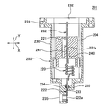
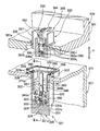
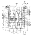
- FIG. 9 is a cross-sectional view taken along line BB in FIG. It is a section perspective view showing the connector concerning a 4th embodiment of the present invention. It is sectional drawing along the II-II line in FIG.
- FIG. 11 is a top view of the connector shown in FIG. 10. It is sectional drawing along the IV-IV line in FIG. It is sectional drawing which shows the state which the connector shown by FIG. 10 began to fit with the other party connector. It is sectional drawing which shows the state which the inner housing shown by FIG. 14 collided with the other party connector, and moved.
- FIG. 16 is a cross-sectional view illustrating a state where the inner housing illustrated in FIG. 15 is pushed back and the connectors are completely fitted to each other.
- FIG. 20 is a cross-sectional view of the connector shown in FIG. 19.
- FIG. 20 is a perspective view of the holder shown in FIG. 19.
- FIG. 22 is a cross-sectional view taken along the line CC in FIG. 21.
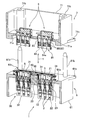
- the connector 1 is attached to a case 61 of a motor 6 mounted on an electric vehicle or a hybrid vehicle, and a pair of mating connectors 8 attached to a case 71 of an ECU (Electronic Control Unit) 7. And a connector that is electrically connected. That is, the connector 1 is a connector that is directly connected to a pair of mating connectors 8 provided integrally with the ECU 7 when the ECU 7 is mounted on the motor 6.
- the pair of mating connectors 8 are respectively attached to a pair of connector receiving holes 71 a provided in the case 71 of the ECU 7.
- the connector receiving hole 71a penetrates the outer wall of the case 71 and is formed in a shape along the outer surface of the housing main body 83 of the housing 81 described later of the mating connector 8. Further, in the vicinity of the connector receiving hole 71 a of the case 71, a positioning hole 71 b into which the boss 61 b of the motor 6 is inserted and a bolt hole 71 c that overlaps with the bolt hole 61 c of the motor 6 are provided.
- the mating connector 8 includes a plurality of terminal fittings 80 and a synthetic resin housing 81.
- the terminal fitting 80 is inserted into the terminal fitting 2 of the connector 1 and electrically connected to the terminal fitting 2, and is connected to the electric contact portion 82 and is electrically connected to the electric circuit of the ECU 7. And a circuit connection portion (not shown).
- the housing 81 includes a rectangular parallelepiped housing main body 83 that accommodates a plurality of terminal fittings 80, and a hood portion 84 that extends in a cylindrical shape from the end surface of the housing main body 83 facing the connector 1 toward the connector 1. It has been. When the mating connector 8 and the connector 1 are fitted, the hood portion 84 positions an inner housing 5 described later of the connector 1 on the inner side.
- the inside of the hood portion 84 is partitioned by a plurality of partition walls 84a.
- the mating connector 8 and the connector 1 described above are fitted along the longitudinal direction of the electrical contact portion 82 accommodated in the housing body 83. Further, an arrow Y in FIG. 1 represents a fitting direction between the mating connector 8 and the connector 1.
- the connector 1 is attached to a connector receiving hole 61a provided in the case 61 of the motor 6 as shown in FIG.
- the connector receiving hole 61a penetrates the outer wall of the case 61 and is formed in a shape along the outer surface of a pair of outer housing bodies 32 described later of the connector 1. Further, in the vicinity of the connector receiving hole 61a of the case 61, a boss 61b for positioning the ECU, a bolt hole 61c for fixing the ECU, and a bolt hole 61d for fixing the connector in which a nut 91 is embedded (see FIG. 3). ) Etc. are provided.
- the connector 1 includes a plurality of terminal fittings 2, an inner housing 5 that houses and holds a first electrical connection portion 21 described later of each terminal fitting 2, a plurality of terminal fittings 2, and an inner fitting.
- An outer housing 30 that houses the housing 4, a holder 31 that is attached to the outer housing 30, and a fixing member 40 that fixes the holder 31 to the outer housing 30 are provided.
- the terminal fitting 2 is accommodated and held in the inner housing 5 and is disposed at a position near the mating connector 8 of the outer housing 30.
- the first electrical connection portion 21 that is electrically connected to the contact portion 82 and the first electrical connection portion 21 of the outer housing 30 that is disposed at a position farther from the mating connector 8 and is electrically connected to the electrical circuit of the motor 6.
- a second electrical connection portion 22 and a connection portion 23 that connects the first electrical connection portion 21 and the second electrical connection portion 22 to each other while being movably connected to each other are provided.
- the first electrical connection portion 21 is obtained by pressing a metal plate or the like, and is formed separately from the second electrical connection portion 22.
- the first electrical connecting portion 21 is provided with a rectangular plate-shaped flat plate portion 21a and a pair of caulking pieces 21b.
- One end portion of the flat plate portion 21a located on the side away from the second electrical connection portion 22 is positioned outside the inner housing 5 and is inserted into the electrical contact portion 82 of the terminal fitting 80 of the mating connector 8 for electrical contact.
- the unit 82 is electrically connected.
- a locking hole 21c (see FIG. 3) for locking a locking arm 52 (to be described later) of the inner housing 5 is provided in a central portion positioned in the inner housing 5 of the flat plate portion 21a.
- the pair of caulking pieces 21b are provided at the other end portion of the flat plate portion 21a located on the second electrical connection portion 22 side, and are erected from both ends in the width direction of the flat plate portion 21a.
- the pair of caulking pieces 21b are electrically and mechanically connected to the connecting portion 23 by sandwiching the connecting portion 23 between the pair of caulking pieces 21b and the flat plate portion 21a by bending the distal end portion thereof toward the flat plate portion 21a.
- the second electrical connecting portion 22 is obtained by pressing a metal plate.
- the second electrical connection portion 22 is provided with a rectangular plate-shaped flat plate portion 22a and a pair of caulking pieces 22b.
- One end portion of the flat plate portion 22a located on the side away from the first electrical connection portion 21 is exposed outside the outer housing 30.
- a bolt hole 22c is provided at one end of the flat plate portion 22a.
- One end of the flat plate portion 22a is overlaid with terminal fittings constituting the electric circuit of the motor 6, and bolts are attached to the bolt holes provided in the terminal fittings and the bolt holes 22c. It is electrically and mechanically connected to the bracket. Further, the central portion in the longitudinal direction of the flat plate portion 22 a is accommodated in a terminal accommodating chamber 35 a described later of the outer housing 30.
- a packing 92 is attached to the central portion so as to be in close contact with the inner surface of the terminal accommodating chamber 35a and keep the inner surface of the terminal accommodating chamber 35a and the second electrical connection portion 22 watertight.
- the pair of caulking pieces 22b are provided at the other end portion of the flat plate portion 22a located on the first electrical connection portion 21 side, and are erected from both ends in the width direction of the flat plate portion 22a.
- the pair of caulking pieces 22b are electrically and mechanically connected to the connecting portion 23 by sandwiching the connecting portion 23 between the pair of caulking pieces 22b and the flat plate portion 22a. .
- the connecting portion 23 includes a braided wire 23a and a covering portion 23b covering the braided wire 23a.
- the braided wire 23a is formed by knitting a plurality of metal strands into a strip shape, and has flexibility.
- the covering portion 23b is made of an insulating synthetic resin and has flexibility. Moreover, the coating
- Such a connecting portion 23 is formed to be more flexible than the first electrical connecting portion 21 and the second electrical connecting portion 22. Further, the connecting portion 23 is formed to be longer than the distance between the first electrical connection portion 21 and the second electrical connection portion 22 accommodated in the outer housing 30. That is, the connecting portion 23 is accommodated in the outer housing 30 in a bent state.
- connection part 23 the coating
- Such a connecting portion 23 is electrically connected to the first electric connecting portion 21 and the second electric connecting portion 22 by caulking both ends of the exposed braided wire 23a to the caulking pieces 21b and 22b as described above. Mechanically connected.
- the connecting portion 23 is composed of the braided wire 23a, a round cross-section having a core wire formed by twisting a plurality of strands and a covering portion covering the core wire.
- the flexibility can be made larger than that of the pattern electric wire.
- this connection part 23 can deform
- the outer housing 30 is made of an insulating synthetic resin.
- the outer housing 30 is integrally provided with a pair of outer housing main bodies 32, a connecting body 33 that connects the pair of outer housing main bodies 32, and a flange portion 34.
- the pair of outer housing bodies 32 have the same configuration.
- the outer housing main body 32 includes a housing portion 36 in which the inner housing 5 that houses and supports the first electrical connection portion 21 is movably accommodated in all directions, and a second electrical connection.
- the fixing portion 35 to which the portion 22 is fixed and the terminal exposed portion 35b are integrally provided.
- the fixing part 35 is formed in a block shape.
- the fixed portion 35 is provided with a plurality of terminal accommodating chambers 35a penetrating the fixed portion 35 along the arrow Y direction.
- Each of the terminal accommodating chambers 35 a accommodates a central portion in the longitudinal direction of the flat plate portion 22 a of the second electrical connection portion 22.
- the terminal exposed portion 35b is formed to extend from an end surface of the fixed portion 35 away from the accommodating portion 36.
- the terminal exposed portion 35b positions the one end portion of the flat plate portion 22a positioned outside the terminal accommodating chamber 35a on the surface.
- a nut 93 is embedded in the terminal exposed portion 35b, into which a bolt passed through the bolt hole 22c described above is screwed.
- reference numeral 35c in FIG. 3 is a bolt hole through which the bolt is passed.
- the housing portion 36 is formed to extend in a cylindrical shape from an end surface of the fixed portion 35 away from the terminal exposed portion 35b.
- Such an accommodating portion 36 accommodates and supports the other end portion of the flat plate portion 22a of the second electrical connecting portion 22, the connecting portion 23, the first electrical connecting portion 21, and the first electrical connecting portion 21.
- An inner housing 5 is accommodated.
- the connecting body 33 has one end connected to the outer peripheral surface of the one outer housing main body 32 near the mating connector 8 and the other end near the mating connector 8 of the other outer housing main body 32. It is connected to the outer peripheral surface.
- the coupling body 33 couples the pair of outer housing bodies 32 to each other so that the central axes of the pair of outer housing bodies 32 are parallel to each other.
- the flange portion 34 is provided at an end portion of the coupling body 33 and the pair of outer housing main bodies 32 near the mating connector 8, and protrudes from the outer peripheral surfaces of the coupling body 33 and the pair of outer housing main bodies 32 in a bowl shape. It is provided in an annular shape.
- the flange portion 34 is overlaid on the outer surface of the case 61 in a state where the coupling body 33 and the pair of outer housing main bodies 32 are inserted into the connector receiving holes 61a.
- a mounting groove 34a is provided on each of the lower surface of the flange portion 34 that overlaps the case 61 and the upper surface of the ECU 7 that overlaps the case 71 of the ECU 7 opposite to the lower surface.
- Each mounting groove 34 a is formed in an annular shape over the entire circumference of the flange portion 34.
- An annular packing 94 a is attached to the attachment groove 34 a provided on the lower surface of the flange portion 34. The packing 94a is in close contact with the outer surface of the case 61 to keep the case 61 and the outer housing 30 watertight.
- An annular packing 94 b is attached to the attachment groove 34 a provided on the upper surface of the flange portion 34. The packing 94b is in close contact with the outer surface of the case 71 of the ECU 7 and keeps the space between the case 71 and the outer housing 30 watertight.
- a recess 36a in which a flange portion 39 (to be described later) of the holder 31 is positioned is provided.
- a plurality of bolting pieces 34c provided with bolt holes 34b are provided on the outer peripheral surface of the flange portion 34.
- the bolting piece 34c is overlaid on the outer surface of the case 61 with the connecting body 33 and the pair of outer housing main bodies 32 inserted into the connector receiving holes 61a, and the bolt holes 34b are provided in the bolt holes 61d provided in the case 61. Is superimposed on.
- the outer housing 30, that is, the connector 1 is attached to the case 61 by screwing the bolts 95 into the bolt holes 34 b and 61 d.
- the holder 31 is made of an insulating synthetic resin. As shown in FIG. 1, two holders 31 are provided, and one holder 31 is attached in each housing portion 36 of each outer housing 30. As shown in FIGS. 2 and 3, each holder 31 is provided with a cylindrical portion 37, a flange portion 39, and a pair of elastic contact portions 38.
- the cylindrical portion 37 is formed in a cylindrical shape having an outer diameter smaller than the inner diameter of the accommodating portion 36.
- the cylinder part 37 is attached in the accommodating part 36 with a gap between the inner side surface of the accommodating part 36.
- the inner housing 5 to which the first electrical connection portion 21 is attached is accommodated in a cylinder portion 37 attached to the accommodation portion 36 so as to be movable in all directions.
- the housing 81 of the mating connector 8 is inserted into a cylindrical portion 37 attached in the accommodating portion 36.
- the flange portion 39 protrudes in a bowl shape from the outer peripheral surface of the cylindrical portion 37 and is formed in an annular shape over the entire circumference of the cylindrical portion 37.
- the flange portion 39 is positioned in the concave portion 36a described above in a state where the cylindrical portion 37 is positioned in the accommodating portion 36.
- the pair of elastic contact portions 38 are provided at locations where the cylindrical portion 37 faces each other.
- the elastic contact portion 38 is formed in a plate shape extending along the arrow Y direction, and is formed in a double-supported plate shape in which both end portions are connected to the cylindrical portion 37. That is, the elastic contact portion 38 is a portion located between the pair of parallel slits provided by forming a pair of parallel slits in the cylindrical portion 37.
- the elastic contact portion 38 is in elastic contact with an elastic arm 51 (described later) of the inner housing 5. Further, the elastic contact portion 38 bends to the outside of the cylindrical portion 37 by contacting the elastic arm 51 of the inner housing 5.
- the fixing member 40 is obtained by pressing a metal plate.
- the fixing member 40 is formed in a substantially rectangular plate shape, and a bolt hole is provided at the center.
- the fixing member 40 is overlaid on the surface of the coupling body 33 facing the mating connector 8, and both ends thereof are overlaid on the flange portions 39 of the holders 31, respectively, with the bolts 96 passed through the bolt holes. It is fixed to the outer housing 30.
- the fixing member 40 fixes the holder 31 to the outer housing 30 with the flange portion 39 of the holder 31 sandwiched between the fixing member 40 and the outer housing 30.
- the inner housing 5 is made of an insulating synthetic resin. As shown in FIG. 1, two inner housings 5 are provided, and one inner housing 5 is accommodated in each of the two holders 31. As shown in FIG. 2, the inner housing 5 is integrally provided with an inner housing main body 50, a pair of elastic arms 51, and a locking arm 52.
- the inner housing body 50 is formed in a rectangular parallelepiped shape.
- the inner housing body 50 is provided with a plurality of terminal accommodating chambers 50a for accommodating the first electrical connecting portions 21 of the respective terminal fittings 2 respectively.
- Each of the terminal accommodating chambers 50a accommodates the other end portion and the central portion in the longitudinal direction of the flat plate portion 21a of the first electrical connecting portion 21 and the caulking piece 21b.
- a slit 50 b into which the partition wall 84 a of the mating connector 8 enters is provided on the surface of the inner housing body 50 facing the mating connector 8.
- the pair of elastic arms 51 are connected to outer side surfaces located at both ends of the inner housing body 50 in the width direction (indicated by arrows W in FIG. 2), and are extended in a cantilever manner. ing.
- the elastic arm 51 includes a base portion 51a protruding from the outer surface of the inner housing main body 50, and an arm main body 51b extending from the base portion 51a toward the mating connector 8 and extending in a bar shape on the side away from the outer surface of the inner housing main body 50. And are provided.
- Such an elastic arm 51 is formed in the direction in which the free end 51c of the arm main body 51b approaches and separates from the outer surface of the inner housing main body 50, that is, in the width direction of the inner housing main body 50 (indicated by an arrow W in FIG. 2). It is formed to be elastically deformable along. Further, the inner housing 5 is held movably in the holder 31, that is, in the accommodating portion 36, when the free end 51 c of the elastic arm 51 comes into elastic contact with the elastic contact portion 38.
- the locking arm 52 is provided in the terminal accommodating chamber 50a of the inner housing main body 50 as shown in FIG.
- the locking arm 52 has an arm main body 52a that is cantilevered from the inner surface of the terminal accommodating chamber 50a, and a locking hole that is provided at the free end of the arm main body 52a and is provided in the first electrical connection portion 21.
- a locking projection 52b that locks to 21c is provided.
- the free end of the arm body 52a is elastically deformable in the thickness direction of the inner housing body 50 (indicated by an arrow T in FIGS. 2 and 3), that is, in a direction intersecting the elastic deformation direction of the elastic arm 51. Is provided.
- the arm main body 52a is elastically deformed in the thickness direction of the inner housing main body 50 (indicated by an arrow T in FIGS. 2 and 3), so that the first electrical connecting portion 21 is connected to the inner housing main body 50. Attach to the movably.
- the inner housing 5 attached with the first electrical connection portion 21 in the accommodating portion 36 has the elastic arm 51 and the elastic contact portion 38 in the width direction of the inner housing body 50 (indicated by an arrow W in FIG. 2).
- the first electrical connecting portion 21 attached to the inner housing main body 50 is supported in the accommodating portion 36 so as to be movable in the width direction of the inner housing main body 50.
- the inner housing 5 is configured such that the arm main body 52a of the locking arm 52 is elastically deformed along the thickness direction of the inner housing main body 50 (indicated by an arrow T in FIGS. Is supported in the accommodating portion 36 so as to be movable in the thickness direction of the inner housing body 50 (indicated by an arrow T in FIGS. 2 and 3).
- the direction in which the elastic arm 51 is elastically deformed and the first electrical connecting portion 21 moves is the direction intersecting the direction in which the locking arm 52 is elastically deformed and the first electrical connecting portion 21 is moved. It is said that. Accordingly, the degree of freedom in the movement direction of the first electrical connection portion 21 is improved, and it becomes easier to cope with the positional deviation.
- the packing 92 is attached to the second electrical connection portion 22 of the terminal fitting 2. Then, the inner housing 5 to which the terminal fitting 2 and the first electrical connection portion 21 are attached is inserted into the outer housing 30 from the opening of the accommodation portion 36, and the second electrical connection portion 22 is inserted into the terminal accommodation chamber 35 a of the fixing portion 35. The inner housing 5 having the first electrical connection portion 21 attached thereto is inserted into the housing portion 36, that is, the holder 31. Thus, the connector 1 is assembled.
- the connector 1 assembled as described above is inserted into the connector receiving hole 61a, the flange portion 34 of the outer housing 30 is overlaid on the outer surface of the case 61, and the bolt hole 34b of the bolting piece 34c and the bolt hole of the case 61 are overlapped.
- a bolt 95 is screwed to 61 d and attached to the case 61 of the motor 6.
- the terminal metal fixture which comprises the electric circuit of the motor 6 is piled up on the 2nd electrical connection part 22 located on the surface of the terminal exposure part 35b, and the bolt hole and bolt hole 22c, 35c which were provided in this terminal metal fitting are piled up.
- the bolt is screwed to electrically connect the electric circuit of the motor 6 and the second electric connecting portion 22.
- the inner housing body 50 moves in the holder 31, and the elastic arm 51, the elastic contact portion 38, The locking arm 52 and the connecting portion 23 are elastically deformed to absorb the displacement. Then, the first electrical connection portion 21 is completely inserted into the electrical contact portion 82 and the first electrical connection portion 21 and the electrical contact portion 82 are electrically connected. Thus, the connector 1 and the mating connector 8 are fitted, and the motor 6 and the ECU 7 are electrically connected.
- the inner housing main body 50 to which the first electrical connection portion 21 is attached moves in the holder 31 when the mating connector 8 is fitted, and the elastic arm 51 and the elastic contact portion 38.
- the locking arm 52 and the connecting portion 23 are elastically deformed, the displacement in all directions between the first electrical connection portion 21 of the terminal fitting 2 and the terminal fitting 80 of the mating connector 8 is absorbed.
- the mating connector 8 can be securely fitted.
- the elastic arm 51 is elastically deformed
- the elastic contact portion 38 is elastically deformed toward the inner side surface of the accommodating portion 36, so that a large load is not applied to the elastically deformed elastic arm 51. Can be prevented from being damaged.
- the second electrical connection portion 22 is fixed to the fixed portion 35 and does not move. It is possible to prevent the connection reliability between the electrical connection portion 22 and the terminal fitting constituting the electrical circuit of the motor 6 that is electrically connected to the second electrical connection portion 22 from being affected. Moreover, when the 1st electrical connection part 21 moves as mentioned above, since the flexible connection part 23 elastically deforms, distortion arises in the 1st electrical connection part 21 and the 2nd electrical connection part 22. FIG. Can be prevented.
- the elastic arm 51, the elastic contact portion 38, and the connecting portion 23 are elastically deformed to absorb the vibration, so that the terminal fitting 2 and the mating connector 8 terminal fitting. It is possible to prevent the connection reliability with 80 from being affected.
- the connector 1 of the present invention since the connector 1 of the present invention includes the holder 31 that is mounted in the housing portion 36, the strength of the housing portion 36 can be improved. For this reason, it is possible to prevent the outer housing 30 and the like from being damaged due to an impact when mated with the mating connector 8.
- the connector 1 is attached to the case 61 of the motor 6.
- the connector 1 of the present invention may be attached to the case of another electronic device.
- the mating connector 8 may be attached to a case of an electronic device other than the ECU 7.
- the connecting portion 23 is composed of the braided wire 23a and the covering portion 23b.
- the connector of the present invention may be less flexible, but a plurality of strands may be formed.
- the electric wire may be provided with a core wire formed by twisting and a covering portion that covers the core wire.
- the connection part 23 may be comprised only of the braided wire 23a, without the coating
- the connecting portion 23 may have any shape or material as long as the connecting portion 23 is more flexible and conductive than the first electric connecting portion 21 and the second electric connecting portion 22.
- the locking arm 52 is locked to the first electrical connecting portion 21.
- the connector of the present invention does not include the locking arm 52 and the first electrical connecting portion 21 is provided. May be insert-molded in the inner housing body 50. Further, the direction in which the locking arm 52 is elastically deformed may be parallel to the direction in which the elastic arm 51 is elastically deformed, although the degree of freedom of movement of the first electrical connecting portion 21 may be reduced.
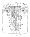
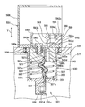
- the connector 101 is a connector that is fitted to the mating connector 111 and electrically connected to the mating connector 111, as shown in FIG.
- the mating connector 111 includes a cylindrical housing 113 and a terminal fitting 112 accommodated in the housing 113.
- the terminal fitting 112 is formed in a cylindrical shape, that is, a female shape by a metal plate.
- the terminal fitting 112 is provided with a plurality of spring pieces 112 a that are elastically deformable along the radial direction of the terminal fitting 112 by providing a plurality of slits on the cylindrical outer wall.
- the plurality of spring pieces 112a elastically contact a first electrical connection portion 121 of a terminal fitting 102, which will be described later, of the connector 101 and urge the first electrical connection portion 121 inward.
- the arrow Y represents the fitting direction between the mating connector 111 and the connector 101
- the arrow X represents the direction orthogonal to the fitting direction
- the connector 101 includes a terminal fitting 102, an inner housing 104 that accommodates and holds a first electrical connecting portion 121 (described later) of the terminal fitting 102, and the terminal fitting 102 and the inner housing 104. And an outer housing 108 for housing the housing.
- the terminal fitting 102 includes a first electrical connection portion 121 that is electrically connected to the terminal fitting 112 of the mating connector 111, and a terminal fitting (not shown) (for example, an electric circuit of an electronic device).
- the first electrical connection portion 121 is formed of a conductive metal material in a rod shape, that is, a male shape.
- the first electrical connection portion 121 is inserted into the terminal fitting 112 of the mating connector 111. Further, the first electrical connecting portion 121 is biased toward the inner side of the terminal fitting 112 by the plurality of spring pieces 112a of the terminal fitting 112, so that the electrical connection state with the terminal fitting 112 is maintained. Further, the plurality of spring pieces 112 a of the terminal fitting 112 follows the movement of the first electrical connecting portion 121 in the arrow X direction.
- the second electrical connection portion 122 is formed in a cylindrical shape from a conductive metal material.
- the second electrical connection portion 122 is provided with a receiving hole 126 formed in a concave shape from an end portion away from the first electrical connection portion 121.
- the second electrical connection portion 122 is electrically connected to a terminal fitting (not shown) inserted into the accommodation hole 126.
- the connecting part 120 is obtained by pressing a metal plate.
- the connecting portion 120 includes an annular first annular portion 123 attached to an end portion of the first electrical connection portion 121 near the second electrical connection portion 122, and a proximity of the first electrical connection portion 121 of the second electrical connection portion 122.
- An annular second annular portion 124 attached to the end portion of the first annular portion 123, and one end portion connected to the first annular portion 123 and the other end portion connected to the second annular portion 124.
- a plurality of arcuate portions 125 bent in an arcuate shape between the two annular portions 124 are integrally provided.
- first annular portion 123 and the second annular portion 124 are wound around the end portion of the first electrical connection portion 121 and the end portion of the second electrical connection portion 122, and these first electrical connection portions.
- first electrical connection portion 121 and the end portion of the second electrical connection portion 122 By being welded to 121 and the second electrical connection portion 122, the outer periphery of the first electrical connection portion 121 and the outer periphery of the second electrical connection portion 122 are attached in a ring shape.
- the first annular portion 123 and the second annular portion 124 are electrically connected to the first electrical connection portion 121 and the second electrical connection portion 122.
- first annular portion 123 and the second annular portion 124 are welded to the first electrical connection portion 121 and the second electrical connection portion 122, respectively, but in the present invention, the first annular portion 123 and The second annular portion 124 may be configured to crimp the first electrical connection portion 121 and the second electrical connection portion 122, respectively.
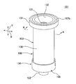
- the plurality of arcuate portions 125 are bent in an arcuate shape that protrudes away from each other, and have a spherical shape as a whole. Further, the arcuate portion 125 is bent and plastically deformed in the state shown in FIG. That is, the connecting portion 120 shown in FIG. 7 is in a state where no external force is applied.
- the connecting portion 120 having the above configuration is elastically deformable in all directions as a whole because each of the plurality of arcuate portions 125 is formed to be elastically deformable.
- “all directions” are the direction in which the first electrical connection portion 121 and the second electrical connection portion 122 are aligned and the direction that intersects the alignment direction.
- Such a connecting part 120 is formed by elastically deforming the plurality of arcuate parts 125 so that the first electrical connection part 121 and the second electrical connection part 122 are connected in all directions, that is, the first electrical connection part 121 and the second electrical connection part. It connects so that it can move freely in the direction of alignment with the connecting portion 122 and the direction that intersects the direction of alignment.
- the inner housing 104 is formed in a cylindrical shape from a synthetic resin, and a central portion in the longitudinal direction of the first electrical connection portion 121 is attached to the inner side.
- the outer housing 108 is provided with an outer housing main body 103 in which an inner housing 104 that houses and holds the first electric connection portion 121 is movably accommodated in all directions, and a second electric connection.
- a fixing portion 134 to which the portion 122 is fixed and packings 107 a and 107 b attached to a flange portion 131 provided at one end portion of the outer housing main body 103 are provided.
- the outer housing main body 103 is made of synthetic resin.
- the outer housing main body 103 includes a cylindrical housing portion 130 extending in the arrow Y direction, and a flange extending in a hook shape outside the housing portion 130 along the arrow X direction from one end portion of the housing portion 130 in the arrow Y direction.
- the part 131 is provided integrally.
- the terminal fitting 102 is accommodated in the accommodating portion 130 in such a direction that the first electric connecting portion 121 is positioned at one end portion of the accommodating portion 130 and the second electric connecting portion 122 is positioned at the other end portion of the accommodating portion 130.
- the inner housing 104 that houses and holds the first electrical connection portion 121 is housed in the housing portion 130 in a state of being spaced from the inner surface of the housing portion 130. This interval is an interval for the first electrical connection part 121 to move in the direction intersecting the arrow Y.
- the above-described mating connector 111 is inserted into the housing portion 130 through the opening 132 located at one end of the housing portion 130.
- the fixing portion 134 is attached to the outer periphery of the second electrical connection portion 122 and press-fitted into the housing portion 130, the cap 106 attached to the other end of the housing portion 130, and the housing portion 130. And the other end.
- the water stop cock 105 is formed in a cylindrical shape from an elastically deformable synthetic resin, that is, synthetic rubber.
- the stop cock 105 is press-fitted into the other end portion of the accommodating portion 130 with the central portion in the longitudinal direction of the second electrical connection portion 122 attached inside. Further, the stop cock 105 is in close contact with the outer surface of the second electrical connection part 122 and the inner side surface of the housing part 130. Such a stop cock 105 is press-fitted into the housing portion 130, thereby fixing the second electrical connection portion 122 to the other end portion of the housing portion 130.
- the cap 106 is attached to the other end portion of the housing portion 130 away from the flange portion 131 and closes the opening 133 located at the other end portion to prevent the terminal fitting 102 from coming out of the housing portion 130.
- the cap 106 is provided with an insertion hole through which an end portion of the second electrical connection portion 122 away from the first electrical connection portion 121 is passed. That is, the second electrical connection part 122 is positioned outside the accommodating part 130 at the end away from the first electrical connection part 121.
- the 2nd electrical connection part 122 is the terminal metal fitting 102 mentioned above.
- the first electrical connecting portion 121 is movable in all the directions described above.
- the connector 101 having the above-described configuration is fitted to the mating connector 111, the plurality of arcuate portions of the connecting portion 120 so that the first electrical connection portion 121 is inserted into the terminal fitting 112 of the mating connector 111.
- the first electrical connecting portion 121 and the inner housing 104 move in the accommodating portion 130, and all the occurrences between the terminal fitting 112 of the mating connector 111 and the first electrical connecting portion 121 occur. Absorbs misalignment in direction. Therefore, the connector 101 of the present invention can be securely fitted to the mating connector 111.
- the plurality of arcuate portions 125 of the connecting portion 120 are elastically deformed by the impact load applied to the first electrical connecting portion 121 and the inner housing 104 by fitting with the mating connector 111. Can be absorbed by.
- the second electrical connecting portion 122 is electrically connected to the first electrical connecting portion 121 via the connecting portion 120, the first electrical connecting portion is fitted by mating with the mating connector 111. Regardless of which direction the 121 moves, the second electrical connection portion 122 does not move. For this reason, the second electrical connection portion 122 and a terminal (not shown) that is electrically connected to the second electrical connection portion 122. It is possible to prevent the connection reliability with the metal fitting from being affected.
- the connector 101 according to the present invention can prevent the vibration from being transmitted to the terminal fitting 102 by absorbing the vibration applied to the outer housing 108 by the connecting portion 120. It is possible to prevent the connection reliability with the terminal fitting 112 from being affected.
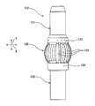
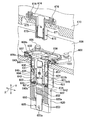
- the connector 201 is a connector that is fitted with a mating connector (not shown) and is electrically connected to the mating connector. Moreover, the arrow Y in FIGS. 8 and 9 represents the fitting direction between the connector 201 and the mating connector, and the arrow X represents the direction orthogonal to the fitting direction. As shown in FIGS. 8 and 9, the connector 201 includes a terminal fitting 202, an inner housing 204 that houses and holds a first electrical connection portion 221 (to be described later) of the terminal fitting 202, and the terminal fitting 202 and the inner housing 204. And an outer housing 203 for housing the housing.
- the terminal fitting 202 includes a first electrical connection portion 221 that is electrically connected to the terminal fitting of the mating connector, a terminal fitting (not shown) (for example, a terminal fitting that constitutes an electric circuit of an electronic device), and the like.
- a second electrical connection part 222 to be connected, and a connection part 220 that connects the first electrical connection part 221 and the second electrical connection part 222 to each other while being movably connected are provided.
- the first electrical connection portion 221 is formed of a conductive metal material in a rod shape, that is, a male shape. The first electrical connection portion 221 is inserted into the terminal fitting of the mating connector.
- the second electrical connection portion 222 is formed in a plate shape from a conductive metal material. Further, the second electrical connection portion 222 is provided with a bolt hole 222 a at an end portion away from the first electrical connection portion 221. The second electrical connection portion 222 is overlapped with a terminal fitting (not shown), and is electrically connected to the terminal fitting by attaching a bolt to the bolt hole 222a.
- the connecting part 220 is composed of a coil spring in which a conductive wire is spirally wound. One end of the connecting portion 220 is welded to the end of the first electrical connecting portion 221 near the second electrical connecting portion 222, and the other end is the end of the second electrical connecting portion 222 near the first electrical connecting portion 221.
- the first electrical connection portion 221 and the second electrical connection portion 222 are electrically connected to each other.
- the connecting portion 220 having the above-described configuration is formed of a coil spring, it can be elastically deformed in all directions.
- “all directions” are the direction in which the first electrical connection portion 221 and the second electrical connection portion 222 are aligned and the direction that intersects the alignment direction.
- Such a connecting part 220 is elastically deformed so that the first electric connecting part 221 and the second electric connecting part 222 are arranged in all directions, that is, the arrangement direction of the first electric connecting part 221 and the second electric connecting part 222. And movably connected in a direction that intersects the direction of alignment.
- the inner housing 204 is made of synthetic resin, and is formed in a cylindrical shape provided with a terminal accommodating chamber 240 that accommodates the first electrical connection portion 221.
- a locking arm 141 is provided in the terminal accommodating chamber 240 to be locked in a locking hole 221a provided in the center in the longitudinal direction of the first electrical connection part 221 and attach the first electrical connection part 221. It has been.
- the outer housing 203 is made of synthetic resin.
- the outer housing 203 includes a cylindrical housing portion 230 in which an inner housing 204 that houses and supports the first electrical connection portion 221 is movably accommodated in all directions, and one end of the housing portion 230 in the arrow Y direction.
- a flange portion 231 extending in a bowl shape outside the housing portion 230 along the arrow X direction from the portion, a fixing portion 234 to which the second electrical connection portion 222 is fixed, and a terminal exposure portion 235 are integrally provided. ing.
- the fixing portion 234 is provided with a terminal insertion hole 233 extending in the arrow Y direction at the center thereof.
- the central portion in the longitudinal direction of the second electrical connection portion 222 is positioned.
- the end portion of the second electrical connecting portion 222 located on the side away from the first electrical connecting portion 221 is exposed to the outside of the outer housing 203 through the terminal insertion hole 233.
- An annular packing 205 is attached to the longitudinal center of the second electrical connection portion 222.
- the second electrical connection portion 222 is fixed to the fixing portion 234 when the packing 205 is press-fitted into the terminal insertion hole 233.
- the terminal exposed portion 235 is formed to extend from the end surface of the fixed portion 234 away from the accommodating portion 230.
- the terminal exposure part 235 positions the end part of the second electrical connection part 222 positioned outside the terminal insertion hole 233 on the surface.
- the terminal exposed portion 235 is embedded with a nut into which a bolt that is passed through the bolt hole 222a described above is screwed.
- the housing portion 230 is formed to extend in a cylindrical shape in the arrow Y direction from an end surface of the fixing portion 234 away from the terminal exposed portion 235.
- the terminal fitting 202 is housed in the housing portion 230 in such a direction that the first electrical connection portion 221 is positioned at one end portion of the housing portion 230 and the connecting portion 220 is positioned at the other end portion of the housing portion 230.
- the inner housing 204 that houses and holds the first electrical connection portion 221 is housed in the housing portion 230 in a state of being spaced from the inner surface of the housing portion 230. This interval is an interval for the first electrical connection part 221 to move in the direction intersecting the arrow Y.
- the mating connector is inserted into the accommodating portion 230 through the opening 232 located at one end of the accommodating portion 230.
- the second electrical connection portion 222 is The first electrical connecting portion 221 is movable in all the directions described above while being fixed to the fixing portion 234.
- the first connecting portion 220 is elastically deformed so that the first electrical connection portion 221 is inserted into the terminal fitting of the mating connector.
- the electrical connection part 221 and the inner housing 204 move in the housing part 230, and absorb the misalignment in all directions that occurs between the terminal fitting of the mating connector and the first electrical connection part 221. Therefore, the connector 201 of the present invention can be securely fitted to the mating connector.
- the connector 201 of the present invention can absorb the impact load applied to the first electrical connection portion 221 and the inner housing 204 by fitting with the mating connector by the connecting portion 220 being elastically deformed.
- the second electrical connection portion 222 is electrically connected to the first electrical connection portion 221 via the connecting portion 220, the first electrical connection portion 221 is engaged with the mating connector. No matter which direction the second electrical connection portion 222 moves, the second electrical connection portion 222 does not move. Therefore, the second electrical connection portion 222 and a terminal fitting (not shown) electrically connected to the second electrical connection portion 222 are provided. It is possible to prevent the connection reliability with the device from being affected.
- the connector 201 of the present invention can prevent the vibration from being transmitted to the terminal fitting 202 when the connecting portion 220 absorbs the vibration applied to the outer housing 203, so that the terminal fitting 202 and the terminal of the mating connector can be prevented. It is possible to prevent the connection reliability with the metal fitting from being affected.
- the second electrical connection portions 122 and 222 are configured to be electrically connected to the terminal fitting, but the second electrical connection of the terminal fitting according to the present invention.
- the part may be configured to be electrically connected to the electric wire.
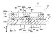
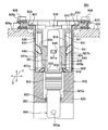
- the connector 301 is attached to a case 371 of a motor 307 mounted on an electric vehicle or a hybrid vehicle, and is fitted to a mating connector 309 attached to a case 381 of an inverter 308. It is a connector that is electrically connected. That is, the connector 301 is a connector that is directly connected to the mating connector 309 provided integrally with the inverter 308 when the inverter 308 is mounted on the motor 307.
- the mating connector 309 is attached to a connector receiving hole 381 a provided in the case 381 of the inverter 308.
- the connector receiving hole 381 a passes through the outer wall of the case 381 and is formed in a shape along the outer surface of the mating connector 309. Further, around the connector receiving hole 381a of the case 381, a recess 381b in which a flange portion 333 described later of the connector 301 is positioned is provided.
- the mating connector 309 includes a terminal fitting 391 and a synthetic resin housing 392 that houses the terminal fitting 391.
- the terminal fitting 391 is inserted into the terminal fitting 302 of the connector 301 and electrically connected to the terminal fitting 302, and the terminal fitting 391 is disposed in the case 381 and electrically connected to the electric circuit of the inverter 308.
- the circuit connection part 394 to be connected to each other, and the connection part 395 for connecting the electrical contact part 393 and the circuit connection part 394 to each other are provided.
- the electrical contact portion 393 has a rectangular plate-shaped flat plate portion 393a, an elastic piece 393b sandwiching the terminal fitting 302 of the connector 301 between the flat plate portion 393a, and a connecting portion 395 between the flat plate portion 393a.
- the housing 392 includes a rectangular parallelepiped housing main body 396 provided with a terminal accommodating chamber 396a for accommodating the electric contact portion 393, a hood portion 397 formed in a rectangular tube shape and connected to the outer periphery of the housing main body 396, and a hood portion.
- a flange portion 398 erected from the outer peripheral surface of 397 is integrally provided. The flange portion 398 is overlaid on the inner surface of the case 381 with the housing body 396 and the hood portion 397 inserted into the connector receiving hole 381a.
- the mating connector 309 and the connector 301 described above are fitted along the arrow Y direction in FIG.
- the connector 301 is attached to a connector receiving hole 371a provided in the case 371 of the motor 307 as shown in FIGS.
- the connector receiving hole 371 a passes through the outer wall of the case 371 and is formed in a shape along the outer surface of the connector 301.
- the connector 301 includes a terminal fitting 302, an inner housing 340 that houses and holds a first electrical connection portion 321, which will be described later, and an outer housing 330 that houses the terminal fitting 302 and the inner housing 340.
- a coil spring 350 as a “force member” and a holder 360 attached to the outer housing 330 are provided.
- the terminal fitting 302 is accommodated and held in the inner housing 340, disposed at a position near the mating connector 309 of the outer housing 330, and electrically connected to the electrical contact portion 393 of the terminal fitting 391 of the mating connector 309.
- a connecting portion 323 that connects the first electrical connecting portion 321 and the second electrical connecting portion 322 to each other while being movably connected thereto is provided.
- the first electrical connection portion 321 is obtained by pressing a metal plate or the like, and is formed separately from the second electrical connection portion 322. As shown in FIG. 11, the first electrical connection portion 321 is provided with a flat plate portion 321a having a rectangular plate shape. One end portion of the flat plate portion 321a located on the side away from the second electrical connection portion 322 is positioned outside the inner housing 340 and is inserted into the electrical contact portion 393 of the terminal fitting 302 of the mating connector 309 to be electrically contacted. 393 is electrically connected.
- a locking hole 321c for locking a locking arm 340d (to be described later) of the inner housing 340 is provided in a central portion of the flat plate portion 321a positioned in the inner housing 340.
- the second electrical connection portion 322 is obtained by pressing a metal plate.
- the second electrical connection portion 322 is provided with a rectangular plate-shaped flat plate portion 322a.
- One end portion of the flat plate portion 322a located on the side away from the first electrical connection portion 321 is exposed outside the outer housing 330.
- a bolt hole 322c is provided at one end of the flat plate portion 322a.
- One end of the flat plate portion 322a is overlaid with terminal fittings constituting the electric circuit of the motor 307, and bolts are attached to the bolt holes provided in the terminal fittings and the bolt holes 322c. It is electrically and mechanically connected to the bracket.
- the central portion in the longitudinal direction of the flat plate portion 322 a is positioned in a terminal insertion hole 331 a described later of the outer housing 330.
- a packing 324 is attached to the central portion of the flat plate portion 322a so as to be in close contact with the inner surface of the terminal insertion hole 331a and keep the inner surface of the terminal insertion hole 331a and the second electrical connection portion 322 watertight.
- the connecting portion 323 includes a braided wire 323a and a covering portion 323b that covers the braided wire 323a.
- the braided wire 323a is formed by knitting a plurality of metal strands into a strip shape, and has flexibility.
- the covering portion 323b is made of an insulating synthetic resin and has flexibility. Moreover, the coating
- Such a connecting portion 323 is formed to be more flexible than the first electric connecting portion 321 and the second electric connecting portion 322. Further, the connecting portion 323 is formed to be longer than the distance between the first electrical connection portion 321 and the second electrical connection portion 322 accommodated in the outer housing 330.
- the connecting portion 323 is accommodated in the outer housing 330 in a bent state.
- the connecting portion 323 has the covering portion 323b peeled off at both ends thereof, and the braided wire 323a is exposed.
- both ends of the exposed braided wire 323a are welded to the first electric connecting part 321 and the second electric connecting part 322, respectively, and the first electric connecting part 321 and the second electric connecting part 322 are connected to each other. Electrically and mechanically connected.
- the connecting portion 323 is composed of the braided wire 323a, so that a round cross-section with a core wire formed by twisting a plurality of strands and a covering portion covering the core wire is provided.
- the flexibility can be made larger than that of the pattern electric wire.
- this connection part 323 can deform
- the inner housing 340 is made of an insulating synthetic resin.
- the inner housing 340 is formed in a rectangular parallelepiped shape having an outer diameter smaller than the inner diameter of the accommodating portion 332 of the outer housing 330 and is accommodated in the accommodating portion 332 so as to be movable in all directions.
- the inner housing 340 is formed such that the other end portion positioned on the side away from the mating connector 309 has a larger diameter than the one end portion positioned near the mating connector 309.
- a contact surface 340a formed flat along a direction orthogonal to the arrow Y direction is formed on the outer peripheral surface between the one end and the other end.
- the contact surface 340 a contacts the end surface of the holder 360.
- the inner housing 340 is provided with a terminal accommodating chamber 340b for accommodating the first electrical connection portion 321 and a spring accommodating groove 340c.
- the terminal accommodating chamber 340b penetrates the inner housing 340 in the arrow Y direction.
- a locking arm 340d for locking to the locking hole 321a provided at the center in the longitudinal direction of the first electrical connection portion 321 and attaching the first electrical connection portion 321. It has been.
- the spring accommodating groove 340 c is formed in a concave shape from the end surface of the inner housing 340 on the side away from the mating connector 309.
- the spring accommodating groove 340c is formed in an annular shape in plan view, and the opening of the terminal accommodating chamber 340b is positioned at the center thereof.
- the spring accommodating groove 340c accommodates the other end of the coil spring 350 inside.
- the outer housing 330 is made of an insulating synthetic resin.
- the outer housing 330 includes a cylindrical housing portion 332 in which an inner housing 340 that houses and supports the first electrical connection portion 321 is movably accommodated in all directions, and the mating connector 309 side of the housing portion 332.
- a flange portion 333 extending in a bowl shape from one end portion positioned outside the housing portion 230, a fixing portion 331 to which the second electrical connection portion 322 is fixed, and a terminal exposure portion 331c are integrally provided. .
- the fixing portion 331 is provided with a terminal insertion hole 331a extending in the arrow Y direction and a spring accommodating groove 331b at the center thereof.
- a central portion in the longitudinal direction of the second electrical connection portion 322 is positioned in the terminal insertion hole 331a.
- the end portion of the second electrical connection portion 322 located on the side away from the first electrical connection portion 321 is exposed to the outside of the outer housing 330 through the terminal insertion hole 331a.
- An annular packing 324 is attached to the central portion in the longitudinal direction of the second electrical connection portion 322.
- the second electrical connection portion 322 is fixed to the fixing portion 331 by the packing 324 being press-fitted into the terminal insertion hole 331a.
- the spring accommodating groove 331b is formed in a concave shape from the end surface facing the mating connector 309.
- the spring accommodating groove 331b is formed in an annular shape in plan view, and the opening of the terminal insertion hole 331a is positioned at the center thereof.
- the spring accommodating groove 331b accommodates one end of the coil spring 350 inside.
- the terminal exposed portion 331c is formed to extend from the end surface of the fixed portion 331 away from the accommodating portion 332.
- the terminal exposed portion 331c positions the end of the second electrical connection portion 322 positioned outside the terminal insertion hole 331a on the surface.
- the terminal exposed portion 331c is provided with a bolt hole 331d in which a nut 334 into which a bolt passed through the bolt hole 322c described above is screwed is embedded.
- the housing portion 332 is formed to extend in a rectangular tube shape in the arrow Y direction from the end surface of the fixing portion 331 away from the terminal exposed portion 331c. Further, the terminal fitting 302 is accommodated in the accommodating portion 332 in such a direction that the first electrical connection portion 321 is positioned at one end portion of the accommodating portion 332 and the connecting portion 323 is positioned at the other end portion of the accommodating portion 332.
- the inner housing 340 that holds and holds the first electrical connection portion 321 is housed in the housing portion 332 in a state of being spaced from the inner surface of the housing portion 332. This interval is an interval for the first electrical connection portion 321 to move in the direction intersecting the arrow Y.
- the mating connector is inserted into the housing portion 332 through an opening located at one end of the housing portion 332.
- the flange portion 333 is overlaid on the outer surface of the case 371 with the accommodating portion 332 being inserted into the connector receiving hole 371a.
- the flange portion 333 is positioned in the recess 381b of the case 381 in a state where the connector 301 and the mating connector 309 are fitted.
- mounting grooves 333a are provided on the lower surface of the flange portion 333 that overlaps the case 371 and the upper surface of the inverter 308 that is opposite to the lower surface and that overlaps the case 381.
- Each mounting groove 333 a is formed in an annular shape over the entire circumference of the flange portion 333.
- An annular packing 336 is attached to the attachment groove 333 a provided on the lower surface of the flange portion 333.
- the packing 336 is in close contact with the outer surface of the case 371 and keeps the space between the case 371 and the outer housing 330 watertight.
- An annular packing 336 is attached to the attachment groove 333 a provided on the upper surface of the flange portion 333.
- the packing 336 is in close contact with the outer surface of the case 381 of the inverter 308 and keeps the space between the case 381 and the outer housing 330 watertight.
- a concave portion 335 is provided on the upper surface of the flange portion 333.
- the bottom surface 335a of the recess 335 is formed flat along a direction orthogonal to the arrow Y direction.
- a flange portion 362 described later of the holder 360 is overlaid on the bottom surface 335a.
- a pair of bolt holes 335b are provided on the bottom surface 335a.
- the coil spring 350 is accommodated in the accommodating portion 332 in a direction in which the central axis direction is parallel to the arrow Y direction, that is, in a direction in which the direction of elastic deformation is parallel to the arrow Y direction. Further, the coil spring 350 is disposed between the fixed portion 331 and the inner housing 340, one end thereof is positioned in the spring accommodating groove 331 b of the fixed portion 331, and the other end is the spring accommodating groove 340 c of the inner housing 340. Positioned within. Such a coil spring 350 biases the inner housing 340 accommodated in the accommodating portion 332 toward the mating connector 309.
- the contact surface 340a of the inner housing 340 biased by the coil spring 350 is in contact with the end surface of the holder 360. It has become.
- the holder 360 is formed of a metal material harder than the synthetic resin that constitutes the outer housing 330 and the inner housing 340.
- the holder 360 is obtained by pressing a metal plate or the like.
- the holder 360 is provided with a cylindrical portion 361 that is accommodated in the accommodating portion 332, and a flange portion 362 that is superimposed on the bottom surface 335 a of the concave portion 335.
- the cylindrical portion 361 is formed in a rectangular tube shape having an outer diameter smaller than the inner diameter of the accommodating portion 332.
- the cylindrical portion 361 has an inner diameter that is larger than the outer diameter of one end portion of the inner housing 340 and an inner diameter that is smaller than the outer diameter of the other end portion of the inner housing 340.
- the flange portion 362 is provided at the end of the cylindrical portion 361 on the mating connector 309 side.
- the flange portion 362 protrudes in a bowl shape from the outer peripheral surface of the cylindrical portion 361 and is formed in an annular shape over the entire circumference of the cylindrical portion 361.
- the flange portion 362 is provided with a pair of holes 363.
- the pair of holes 363 are formed by cutting the outer edge portion of the flange portion 362 into a rectangular shape, and are provided at positions where the central axes of the holder 360 are positioned between each other.
- such a holder 360 is formed by attaching a fastener 366, a bolt 368, and a washer 367 to the bottom surface 335 a of the recess 335, so that the fitting direction between the connector 301 and the mating connector 309, That is, it is attached to the outer housing 330 movably along a direction orthogonal to the arrow Y direction.
- the fastener 366 is obtained by pressing a metal plate. As shown in FIGS. 12 and 13, the fastener 366 has a rectangular plate-like plate portion 366 a smaller than the hole 363 and a pair of standing pieces erected in the same direction from both longitudinal ends of the plate portion 366 a. 366b, and a pair of extending pieces 366c extending in a direction away from the end portions away from the plate portion 366a of the pair of standing pieces 366b (longitudinal direction of the plate portion 366a).
- a bolt hole 366d through which the bolt 368 is passed is provided in the center of the plate portion 366a.
- the overall dimension of the fastener 366 in the longitudinal direction is larger than the longitudinal dimension of the hole 363.
- the distance between the surface overlaid on the bottom surface 335 a of the plate portion 366 a and the surface facing the bottom surface 335 a of the extending piece 366 c is formed to be larger than the thickness of the flange portion 362. That is, the fastener 366 is formed so that the surface of the extending piece 366 c does not contact the surface of the flange portion 362.
- the cylindrical portion 361 of the holder 360 is inserted into the accommodating portion 332 and the flange portion 362 is overlaid on the bottom surface 335a of the recess 335, and then the fastener 360 is attached.
- the plate portion 366 a of the tool 366 is overlaid on the bottom surface 335 a exposed from the hole 363.
- the fasteners 366 are overlapped so that the longitudinal direction of the fastener 366 and the longitudinal direction of the hole 363 are parallel to each other, and the bolt holes 366d of the plate portion 366a and the bolt holes 335b of the concave portion 335 are overlapped.
- the bolt 368 is screwed into the bolt holes 335b and 366d via the washer 367.
- the holder 360 attached to the outer housing 330 is prevented from falling off the outer housing 330 because the portion around the hole 363 is positioned between the bottom surface 335a and the extending piece 366c.
- the fastener 366 is formed so that a gap is formed between the outer edge portion of the plate portion 366a and the inner edge portion of the hole 363, and the extended piece 366c is formed so as not to contact the surface of the flange portion 362. Therefore, the holder 360 has a surface direction of the bottom surface 335a (for example, the direction of the arrow H1 or the arrow H2 shown in FIG. 12 and the direction orthogonal to the arrow Y direction) so that the flange portion 362 slides on the bottom surface 335a.
- the holder 360 is attached to the outer housing 330 so as to be movable along the direction in which the connector 301 and the mating connector 309 are fitted, that is, the direction perpendicular to the arrow Y direction.
- the holder 360 accommodates one end portion of the inner housing 340 in the cylindrical portion 361 while being attached to the outer housing 330. Further, since the inner housing 340 is urged toward the mating connector 309 by the coil spring 350, the contact surface 340a contacts the end surface of the cylindrical portion 361 on the side away from the flange portion 362. This prevents the inner housing 340 from going out of the accommodating portion 332. That is, the end surface of the cylindrical portion 361 on the side away from the flange portion 362 corresponds to a “stopper” described in the claims. Further, when the holder 360 moves along a direction orthogonal to the arrow Y direction, the inner housing 340 moves in the accommodating portion 332 together with the holder 360.
- the first electrical connection portion 321 of the terminal fitting 302 is inserted into the terminal accommodating chamber 340 b of the inner housing 340, and the terminal fitting 302 is attached to the inner housing 340. Further, the packing 324 is attached to the second electrical connection part 322 of the terminal fitting 302. Further, the packing 336 is attached to the packing attachment groove 333 a of the outer housing 330. Next, the coil spring 350 is inserted into the housing portion 332.
- the inner housing 340 to which the terminal fitting 302 and the first electric connection portion 321 are attached is inserted into the outer housing 330 from the opening of the accommodating portion 332, and the second electric connection portion 322 is inserted into the terminal insertion hole 331a of the fixing portion 331.
- the inner housing 340 having the first electrical connection portion 321 attached thereto is inserted into the housing portion 332.
- the holder 360 is inserted into the accommodating portion 332, and one end portion of the inner housing 340 is accommodated in the cylindrical portion 361, and the abutting surface 340 a of the inner housing 340 is pressed by the end surface of the cylindrical portion 361 to coil spring 350.
- the flange portion 362 is overlapped with the bottom surface 335 a of the recess 335.
- the holder 360 is attached to the outer housing 330 using the fastener 366 as described above.
- the connector 301 is assembled.
- the connector 301 assembled as described above is inserted into the connector receiving hole 371a, the flange portion 333 of the outer housing 330 is overlaid on the outer surface of the case 371, and is bolted to be attached to the case 371.
- the terminal metal fitting which comprises the electric circuit of the motor 307 is piled up on the 2nd electrical connection part 322 positioned on the surface of the terminal exposure part 331c, and the bolt hole provided in this terminal metal fitting, the bolt hole 322c, and the bolt hole Bolts are screwed to 331d, and the electric circuit of the motor 307 and the two electric connecting portions 322 are electrically connected.
- the front end surface of the housing body 396 is caused by the impact of overlapping the case 381 having a large weight as shown in FIG.
- the inner housing 340 collides with the front end surface of the inner housing 340, and the inner housing 340 moves to the fixed portion 331 side and elastically deforms in the direction in which the coil spring 350 contracts.
- the coil spring 350 is disposed between the fixed portion 331 and the inner housing 340, thereby preventing the inner housing 340 from colliding with the fixed portion 331.
- the inner housing 340 is pushed back toward the mating connector 309 by the elastic restoring force of the coil spring 350, and the front end surface of the inner housing 340 comes into contact with the front end surface of the housing body 396,
- the electrical connection portion 321 is sandwiched between the flat plate portion 393a and the elastic piece 393b, and the first electrical connection portion 321 and the electrical contact portion 393 are electrically connected.
- the connector 301 and the mating connector 309 are completely fitted, and the motor 307 and the inverter 308 are electrically connected.
- the connector 301 of the present invention is in electrical contact with the holder 360 and the inner housing 340 to which the first electrical connection portion 321 is attached when the mating connector 309 is fitted.
- the misalignment between the portion 393 and the first electrical connection portion 321 can be absorbed, and the mating connector 309 can be securely fitted.
- the connector 301 of the motor 307 and the mating connector 309 of the inverter 308 can be directly fitted without using a wire harness, so the weight of the vehicle body is reduced and the generation of CO 2 is reduced. can do.
- the second electrical connection portion 322 is fixed to the fixed portion 331 and does not move. It is possible to prevent the connection reliability between the electrical connection portion 322 and the terminal fitting constituting the electrical circuit of the motor 307 that is electrically connected to the second electrical connection portion 322 from being affected. Further, as described above, when the first electrical connecting portion 321 moves, the flexible connecting portion 323 is elastically deformed, so that the first electrical connecting portion 321 and the second electrical connecting portion 322 are distorted. Can be prevented.
- the connector 301 of the present invention since the connector 301 of the present invention includes the holder 360 attached in the housing portion 332, the strength of the housing portion 332 can be improved. For this reason, it is possible to prevent the outer housing 330 and the like from being damaged due to an impact when mated with the mating connector 309. Moreover, since the holder 360 is formed of a metal material, the strength of the holder 360 itself can be improved, and therefore the strength of the housing portion 332 can be further improved.
- the connector 301 of the present invention includes the coil spring 350, the inner housing 340 collides with the fixed portion 331 and the housing main body 396 and is damaged by an impact when mated with the mating connector 309. Can be prevented.
- the coil spring 350 and the connecting portion 323 are elastically deformed to absorb the vibration, so that the connection reliability between the terminal fitting 302 and the terminal fitting 391 of the mating connector 309 is reliable. It is possible to prevent the sex from being affected.
- the connector 301 of the present invention can prevent the inner housing 340 from coming out of the accommodating portion 332 because the end surface of the cylindrical portion 361 of the holder 360 contacts the contact surface 340a of the inner housing 340.
- FIG. 17 A connector 401 according to a fifth embodiment of the present invention will be described with reference to FIG. 17, the same components as those in the fourth embodiment described above are denoted by the same reference numerals and description thereof is omitted.
- the connector 401 is attached to a case 371 of a motor 307 mounted on an electric vehicle or a hybrid vehicle, like the connector 301 described in the fourth embodiment, and is fitted with a mating connector attached to the case of the inverter.
- the connector 401 includes three terminal fittings 302, an inner housing 440 that houses and holds the first electrical connection portions 321 of these terminal fittings 302, and the first electrical connection portion of the terminal fittings 302.
- An outer housing 430 provided with an accommodating portion 332 in which an inner housing 440 to which the 321 is attached is movably accommodated and a fixing portion 431 to which the second electrical connection portion 322 of the terminal fitting 302 is fixed;
- the connector 401 has the same configuration as the connector 301 described in the fourth embodiment except that a plurality of terminal fittings 302 are provided and an elastic tube 450 is provided instead of the coil spring 350 as an urging member. It is the composition.
- the inner housing 440 has the same configuration as the inner housing 340 of the fourth embodiment except that three terminal accommodating chambers 440b and two spring accommodating grooves 440c are provided.
- the three terminal accommodating chambers 440b are provided at intervals.
- Each terminal accommodating chamber 440b accommodates the first electrical connection portion 321 of each terminal fitting 302.
- Two spring accommodating grooves 440c are provided so that the openings of the two terminal accommodating chambers 440b located at both ends of the three terminal accommodating chambers 440b are positioned at the centers.
- the outer housing 430 has the same configuration as the outer housing 330 of the fourth embodiment except that the fixed portion 431 is provided with three terminal insertion holes 431a and two spring housing grooves 431b.
- the three terminal insertion holes 431a are provided at intervals.
- Each terminal insertion hole 431 a accommodates the second electrical connection portion 322 of each terminal fitting 302.
- Two spring accommodating grooves 431b are provided so that the openings of the two terminal insertion holes 431a located at both ends of the three terminal insertion holes 431a are respectively positioned at the center.
- the elastic tube 450 is formed in a cylindrical shape from elastically deformable synthetic rubber. Two elastic tubes 450 are provided, and each elastic tube 450 passes the connecting portions 323 of the terminal fittings 302 located at both ends of the three terminal fittings 302 to the inside.
- the elastic tube 450 is integrally provided with a pair of cylindrical portions 451 formed in a cylindrical shape and a bellows-shaped bellows accommodating portion 452 that connects the pair of cylindrical portions 451 to each other.
- One cylindrical portion 451 is positioned in the spring accommodating groove 431 b of the outer housing 430, and the other cylindrical portion 451 is positioned in the spring accommodating groove 431 b of the inner housing 440.
- the inner tube 440 when the housing body of the mating connector collides with the inner housing 440, the inner tube 440 once moves to the fixing portion 431 side and then the elastic tube 450 is moved, as in the fourth embodiment. Therefore, the inner housing 440 can be prevented from being damaged. Furthermore, elastic deformation of the elastic tube 450 can absorb vibrations and can prevent the connection reliability between the terminal fitting 302 and the terminal fitting of the mating connector from being affected. Further, since the holder 360 is formed of a metal material and has high strength, the holder 360 can be prevented from being damaged, and the displacement of the terminal fitting 302 of the connector 401 and the terminal fitting of the mating connector is absorbed by the movement of the holder 360. be able to.
- FIG. 18 A connector 501 according to a sixth embodiment of the present invention will be described with reference to FIG.
- the same components as those of the above-described fourth embodiment are denoted by the same reference numerals, and description thereof is omitted.
- the connector 501 is attached to the case 571 of the motor 507 mounted on the electric vehicle or the hybrid vehicle, and is connected to the case 581 of the inverter 508, similarly to the connector 301 described in the fourth embodiment.
- 509 is a connector fitted to 509, that is, electrically connected.
- the connector 501 is attached with a terminal fitting 502, an inner housing 540 that houses and holds the first electrical connection portion 521 of the terminal fitting 502, and the first electrical connection portion 521 of the terminal fitting 502.
- An outer housing 530 provided with an accommodating portion 332 in which the inner housing 540 is movably accommodated and a fixing portion 331 to which the second electrical connection portion 322 of the terminal fitting 502 is fixed, and a coil as an “urging member” And a spring 350.
- the terminal fitting 502 includes a first electrical connecting portion 521, a second electrical connecting portion 322, and a connecting portion 323 that connects and electrically connects the first electrical connecting portion 521 and the second electrical connecting portion 322 to each other. , Is provided.
- the first electrical connection portion 521 is obtained by pressing a metal plate or the like, and is provided with an L-shaped plate portion 521a having an L-shaped cross section.
- One end of the L-shaped plate portion 521a is accommodated in a terminal accommodating recess 540a of an inner housing 540, which will be described later, exposed outside the connector 501, and electrically connected to the mating connector 509.
- a bolt hole 521d for bolting the terminal fitting 591 of the mating connector 509 is provided at one end of the L-shaped plate portion 521a.
- the other end of the L-shaped plate portion 521a orthogonal to the one end is accommodated in the terminal accommodating chamber 540b of the inner housing 540.
- the other end of the L-shaped plate 521a is provided with a locking hole 521c for locking the locking arm 540d of the inner housing 540.
- the inner housing 540 is made of an insulating synthetic resin.
- the inner housing 540 is formed in a rectangular parallelepiped shape and has a size that can be movably accommodated in the accommodating portion 332 of the outer housing 530.
- the inner housing 540 is provided with a terminal accommodating chamber 540b, a spring accommodating groove 540c, a terminal accommodating recess 540a, and a bolt hole 540e.
- the terminal accommodating recess 540a is formed as a recess from the end surface of the inner housing 540 facing the mating connector 509.
- the terminal accommodating recess 540a accommodates one end portion of the L-shaped plate portion 521a of the terminal fitting 502 and exposes one surface of the one end portion of the L-shaped plate portion 521a to the outside of the connector 501.
- the bolt hole 540e is formed as a recess from the bottom surface of the terminal accommodating recess 540a, and a nut 541 is embedded therein.
- the bolt hole 540e is overlapped with the bolt hole 521d of the L-shaped plate portion 521a.
- the coil spring 350 is not elastically deformed, and a part of the inner housing 540 facing the mating connector 509 is part of the motor 507. It is in a state of protruding from the surface of the case 571.
- the mating connector 509 includes a terminal fitting 591 and a synthetic resin housing 592.
- the terminal fitting 591 is obtained by pressing a metal plate.
- the terminal fitting 591 is integrally provided with an electrical contact portion 593 electrically connected to the terminal fitting 502 of the connector 501 and a circuit connection portion 594 connected to the electrical circuit of the inverter 508 connected to the electrical contact portion 593. Yes.
- the electric contact portion 593 has an L-shaped cross section. One end of the electrical contact portion 593 is provided with a locking hole 593a for locking the locking arm 592d of the housing 592. The other end of the electrical contact portion 593 that is orthogonal to the one end is exposed outside the mating connector 509 and overlaps the terminal fitting 502 of the connector 501. A bolt hole 593 b that overlaps the bolt hole 521 d of the terminal fitting 502 is provided at the other end of the electrical contact portion 593. Further, the terminal fitting 502 and the terminal fitting 591 are electrically and mechanically connected by screwing bolts 595 into the bolt holes 521d and 593b that are overlapped with each other.
- the circuit connection portion 594 is formed in a flat plate shape and extends from one end portion of the electrical contact portion 593 in a direction away from the other end portion of the electrical contact portion 593.
- a terminal fitting constituting the electric circuit of the inverter 508 is overlaid on the circuit connection portion 594.
- the circuit connection portion 594 is provided with a bolt hole 594a that overlaps the bolt hole of the terminal fitting.
- the terminal fitting 591 and the terminal fitting constituting the electric circuit of the inverter 508 are electrically and mechanically connected by screwing a bolt into a bolt hole overlapped with each other.
- the housing 592 is provided with a terminal accommodating chamber 592a for accommodating the electrical contact portion 593 of the terminal fitting 591, a terminal accommodating recess 592b, and a bolt hole 592c.
- a locking arm 592d is provided which is engaged with the electrical contact portion 593 and attaches the electrical contact portion 593 in the terminal accommodating chamber 592a.
- the other end portion of the electrical contact portion 593 accommodated in the terminal accommodating chamber 592a is disposed so as to cover the opening portion of the terminal accommodating chamber 592a facing the connector 501 and exposed outside the connector 509.
- the terminal accommodating recess 592b is formed as a recess from the end surface of the housing 592 away from the connector 501 and accommodates the circuit connection portion 594 of the terminal fitting 591.
- the bolt hole 592c is recessed from the bottom surface of the terminal accommodating recess 592b, and a nut 596 is embedded therein. The bolt hole 592c overlaps the bolt hole 594a of the circuit connecting portion 594.
- the inner housing 540 when the terminal fitting 591 collides with the terminal fitting 502, the inner housing 540 once moves to the fixing portion 331 side and then the elastic recovery of the coil spring 350 is performed as in the fourth embodiment. Since it is pushed back by force, damage to the inner housing 540 can be prevented. Furthermore, since the coil spring 350 is elastically deformed, vibration can be absorbed and connection reliability between the terminal fitting 502 and the terminal fitting 591 of the mating connector 509 can be prevented from being affected.
- the connector 601 is attached to a case 609 of a motor mounted on an automobile, and is fitted to a mating connector 671 attached to an inverter case 670, that is, a connector to be electrically connected. It is. That is, the connector 601 is a connector that is directly connected to the mating connector 671 provided integrally with the inverter when the inverter is mounted on the motor.
- the mating connector 671 includes a female terminal fitting 675 that is electrically connected to the electric circuit of the inverter and is electrically connected to the terminal fitting 605 of the connector 601, and a housing 72 made of synthetic resin.
- the housing 72 is integrally provided with a flange portion 674 fixed to the case 670 with a bolt 676 and a terminal accommodating portion 673 that accommodates the terminal fitting 675.
- the arrow Y represents the fitting direction between the mating connector 671 and the connector 601
- the arrow X represents the direction orthogonal to the fitting direction.
- the connector 601 is fixed to a terminal fitting 605, an inner housing 604 that houses and holds a first electrical connection portion 651 (to be described later) of the terminal fitting 605, and a motor case 609.
- An outer housing 602 that accommodates the terminal fitting 605 and the inner housing 604, a holder 603 that is attached to the outer housing 602, and that is movably mounted in the outer housing 602 in all directions, and packings 606a, 606b, and 692. And.
- the terminal fitting 605 is provided with a first electric connecting portion 651, a second electric connecting portion 653, and a connecting portion 652.
- the first electrical connection portion 651 is formed of a conductive metal in a plate shape, that is, a male shape.
- the first electrical connection portion 651 is inserted inside the female terminal fitting 675 of the mating connector 671, that is, is fitted and electrically connected to the terminal fitting 675. Further, the first electrical connection portion 651 is provided with a locking hole 651 a that is locked to a locking lock 644 described later of the inner housing 604.
- the second electrical connection portion 653 is formed in a plate shape from a conductive metal.
- the second electrical connection portion 653 is electrically connected to an electrical circuit in the motor case 609.
- the second electrical connection portion 653 is provided with a round hole 653a through which a bolt is passed when being fixed to the electric circuit of the motor.
- the connecting portion 652 is formed of a braided wire that is a flexible conductive member.
- the connecting portion 652 is disposed between the first electric connecting portion 651 and the second electric connecting portion 653, and connects the first electric connecting portion 651 and the second electric connecting portion 653 to each other while being movable. is doing. Further, the connecting portion 652, the first electrical connecting portion 651, and the second electrical connecting portion 653 are electrically connected to each other by ultrasonic bonding.
- the inner housing 604 is made of synthetic resin.
- the inner housing 604 includes a terminal housing portion 641 having a bottomed tubular shape, that is, a square tubular shape, which accommodates a distal end portion of the terminal fitting 605 away from the connecting portion 652 of the first electrical connection portion 651, and a terminal housing portion 641.
- a terminal mounting portion 640 that extends from the inner bottom surface to the side away from the opening of the terminal accommodating portion 641 and attaches the rear end portion of the first electrical connecting portion 651 near the connecting portion 652 is integrally provided.
- a space is provided between the inner surface of the terminal accommodating portion 641 and the first electrical connection portion 651 for accommodating the terminal accommodating portion 673 of the mating connector 671 inserted from the opening of the terminal accommodating portion 641. It has been.
- the mating connector 671 accommodates the first electrical connecting portion 651 in the terminal fitting 675 when the terminal accommodating portion 673 is fitted into the space of the terminal accommodating portion 641.
- the terminal mounting portion 640 is disposed on the inner surface of the through hole 640a and the through hole 640a that communicates with the internal space of the terminal accommodating portion 641 and passes the rear end portion of the first electrical connection portion 651.
- a locking lock 644 that locks in the locking hole 651a of the electrical connection portion 651 is provided.
- the terminal attachment portion 640 attaches the first electrical connection portion 651 by the engagement lock 644 engaging with the engagement hole 651a.
- reference numeral 643 shown in FIG. 20 and the like indicates a “front end face” of the inner housing 604, and reference numeral 642 indicates a “rear end face” of the inner housing 604.
- Reference numeral 645 denotes an “outer surface” of the inner housing 604.
- the end surface of the inner housing 604 on the side where the terminal accommodating portion 641 is provided is referred to as “front end surface 643”
- the end surface of the inner housing 604 on the side where the terminal mounting portion 640 is provided is referred to as “rear end surface”. 642 ".
- the through hole 640 a is opened to the rear end surface 642 side of the inner housing 604, and the rear end portion of the first electrical connection portion 651 protrudes from the rear end surface 642.
- the outer housing 602 is made of synthetic resin.
- the outer housing 602 includes a housing portion 621 having a bottomed cylindrical shape, that is, a rectangular tube shape, opened to the front, that is, the mating connector 671 side, and an outer side of the housing portion 621 from an end portion of the housing portion 621 on the opening side.
- a flange portion 623 extending in a bowl shape and a fixing portion 620 extending from the inner bottom surface 621a of the housing portion 621 to the side away from the opening portion of the housing portion 621 are integrally provided.
- the housing portion 621 has the inner housing 604 inward so that the front end surface 643 of the inner housing 604 is positioned on the opening side of the housing portion 621 and the rear end surface 642 of the inner housing 604 is positioned on the inner bottom surface 621a side. Accommodate. Further, the inner diameter of the accommodating portion 621 is formed larger than the outer diameter of the inner housing 604. Further, the depth of the accommodating portion 621 in the arrow Y direction is formed to be greater than the total length of the inner housing 604 in the arrow Y direction. From this, the accommodating part 621 accommodates the inner housing 604 movably in all directions.
- the flange 623 is overlaid on the outer surface of the case 609 and fixed to the case 609 with a bolt 608.
- a packing 606 a is attached between the flange portion 623 and the outer surface of the case 609.
- the packing 606a keeps the space between the flange portion 623 and the outer surface of the case 609 watertight.
- a packing 606 b is attached between the flange portion 623 and the outer surface of the inverter case 670.
- the packing 606b keeps the space between the flange portion 623 and the outer surface of the case 670 watertight.
- the packings 606a and 606b are provided in an annular shape over the entire circumference of the flange portion 623, that is, the entire circumference of the outer housing 602.
- the fixing portion 620 is provided with a through hole 620a that communicates with the internal space of the accommodating portion 621 and accommodates the connecting portion 652 of the terminal fitting 605 and the second electrical connecting portion 653. Further, the through hole 620a opens to the rear end surface side away from the housing portion 621 of the fixing portion 620, and causes the rear end portion of the second electrical connection portion 653 to protrude from the rear end surface of the fixing portion 620. Further, as described above, the rear end portion of the second electrical connection portion 653 protruding from the rear end surface of the fixing portion 620 is electrically connected to the electric circuit of the motor by passing a bolt through the round hole 653a.
- annular packing 692 that is in close contact with the inner surface of the through hole 620a and keeps the space between the inner surface of the through hole 620a and the second electric connection portion 653 at the center in the longitudinal direction of the second electric connection portion 653. It is attached.
- the packing 692 is attached to the outer periphery of the second electrical connection portion 653 and is press-fitted into the through hole 620a, whereby the second electrical connection portion 653 is fixed to the fixing portion 620.
- the holder 603 is obtained by pressing a thin metal plate. As shown in FIGS. 21 and 22, the holder 603 includes a cylindrical portion 630, four first springs 634 as “biasing portions”, and “second biasing portions” and “biasing members”. Two second springs 635, two stoppers 636, and two flange portions 633 are integrally provided.
- the cylindrical portion 630 is formed in a square cylindrical shape by a pair of walls 631 facing each other and a pair of walls 632 facing each other.
- the cylindrical portion 630 positions the inner housing 604 inside.
- the four first springs 634 are formed by cutting a part of each wall 631, 32 of the cylindrical portion 630 into a cantilevered band shape, and bending it into a U shape so as to protrude inside the cylindrical portion 630. Is formed.
- the two second springs 635 extend in a cantilevered manner from one end of each of the pair of walls 631 of the cylindrical portion 630, and project toward the inside of the cylindrical portion 630 and the other end portion side of the cylindrical portion 630. In this way, it is bent into a U shape.
- the two stoppers 636 are extended from the other end of each of the pair of walls 632 of the cylindrical portion 630.
- the two stoppers 636 are configured to contact the front end surface 643 of the inner housing 604 after the inner housing 604 is inserted into the cylindrical portion 630 from the opening on the other end side of the cylindrical portion 630, that is, to cover the two stoppers 636. , Bent and formed.
- the two flange portions 633 are extended from the other end portions of the pair of walls 631 and are formed to be bent outside the cylindrical portion 630.
- the flange portion 633 is provided with a round hole 633a through which the bolt 607 is passed.
- the flange portion 633 is overlapped with the flange portion 623 of the outer housing 602 and is fixed to the flange portion 623 by the bolt 7 passed through the round hole 633a.
- Such a holder 603 is attached to the outer housing 602 by being inserted into the accommodating portion 621 from the opening of the accommodating portion 621 with the outer surface of the cylindrical portion 630 extending along the inner side surface 621b of the accommodating portion 621.
- the holder 603 includes four first springs 634 arranged so as to surround the inner housing 604 in a state where the inner housing 604 is accommodated inside the cylindrical portion 630 and attached to the outer housing 602.
- the outer surface 645 of 604 is urged in the arrow X direction toward the inner surface 621b of the housing portion 621. That is, the four first springs 634 urge the inner housing 604 toward the center of the inner housing 604.
- the holder 603 attaches the inner housing 604 in the accommodating portion 621 of the outer housing 602 so as to be movable in all directions.
- the first spring 634 and the second spring of the holder 603 are inserted so that the first electrical connection portion 651 is inserted into the terminal fitting 675 of the mating connector 671. Due to the elastic deformation of 635, the inner housing 604 moves in the housing portion 621 of the outer housing 602, and absorbs the positional deviation between the terminal fitting 675 of the mating connector 671 and the first electrical connection portion 651.
- the connector 601 configured as described above absorbs the impact load applied to the inner housing 604 by fitting with the mating connector 671 as the second spring 635 elastically deforms. This prevents the inner housing 604 from colliding with the inner bottom surface 621a of the accommodating portion 621, that is, the fixing portion 620, and being damaged. Note that the impact load applied to the inner housing 604 at the time of mating with the mating connector 671 integrated with the inverter becomes large as the weight of the inverter is added.
- the inner housing 604 is pushed back to the mating connector 671 side by the elastic restoring force of the second spring 635, but when the stopper 636 abuts against the front end surface 643 of the inner housing 604 and presses the front end surface 643, this The inner housing 604 is prevented from going out of the opening of the housing portion 621.
- the connector 601 having the above configuration makes it difficult for the first spring 634 and the second spring 635 to absorb the vibration of the case 609 caused by the driving of the motor or the like, so that the vibration is hardly transmitted to the inner housing 604.
- the connector 601 having the above-described configuration is fitted to the mating connector 671 because the second electrical connection portion 653 is electrically connected to the first electrical connection portion 651 via the connecting portion 652 formed of a braided wire. Even if the inner housing 604 and the first electrical connection portion 651 are moved by this, the second electrical connection portion 653 does not move, and stress is generated in the member electrically connected to the second electrical connection portion 653. Can be prevented. Moreover, it can prevent that the connection reliability of the 2nd electrical connection part 653 and the said member falls.
- the fitting with the mating connector 671 is performed.
- the positional deviation generated between the terminal fitting 605 and the terminal fitting 675 of the mating connector 671 can be absorbed, and can be securely fitted to the mating connector 671.
- the terminal metal fitting 605, the inner housing 604, and the outer housing 602 can be prevented from being damaged by the impact, the inner housing 604 can be prevented from coming out of the accommodating portion 621, the vibration can be absorbed, and the number of parts can be reduced. Therefore, it is possible to provide the connector 601 having a simple configuration with few.
- the stopper 636 is formed by bending the inner housing 604 inside the cylindrical portion 630 and then bending it so as to contact the front end face 643 of the inner housing 604.
- the outer housing 602 and the stopper 636 can be formed in a simple shape as compared with the case of using a “stopper structured to be assembled to the outer housing after being accommodated in the inner housing”.
- the connector 601 is fixed to the motor case 609
- the connector of the present invention may be fixed to any case.
- the connecting portion 652, the first electrical connecting portion 651, and the second electrical connecting portion 653 are electrically connected to each other by ultrasonic bonding.
- the connecting portion 652 and The first electrical connection portion 651 and the second electrical connection portion 653 may be caulked with metal fittings or the like and electrically connected to each other.
- the connecting portion of the present invention is not limited to a braided wire, and may be any member as long as it is formed of a conductive material and has flexibility or flexibility.
- first springs are provided, and four or more may be provided. Further, it is sufficient that at least one “second spring” and “stopper” are provided, and two or more “second springs” may be provided.
Landscapes
- Details Of Connecting Devices For Male And Female Coupling (AREA)
- Connector Housings Or Holding Contact Members (AREA)
Abstract
Provided is a connector that can absorb the deviation in position between metal contacts of a terminal and metal contacts of a terminal of a connector on the other side, and which can intermesh securely with the connector on the other side. The connector (1) is provided with metal contacts of a terminal (2), an inner housing (5), and an outer housing (30) that accommodates the metal contacts of a terminal (2) and the inner housing (5). Each metal contact of the terminal (2) is provided with: a first electrical connection section (21) that is accommodated and retained within the inner housing (5), and which is to be electrically connected to the connector on the other side; a second electrical connection section (22); and a connecting section (23) that is formed by conductive material, which has flexibility, and which connects the first electrical connection section (21) and the second electrical connection section (22) in a mutually movable state, and which also connects the two connection sections electrically. The outer housing (30) is provided with: an accommodating section (36) within which the inner housing (5) that had the first electrical connection section (21) accommodated therein is to be accommodated in a movable state; and an anchoring section (35) where the second electrical connection section (22) is to be anchored.
Description
本発明は、端子金具と、前記端子金具を収容するインナハウジングと、前記端子金具及び前記インナハウジングを収容するアウタハウジングと、を備えたコネクタに関するものである。
The present invention relates to a connector including a terminal metal fitting, an inner housing that accommodates the terminal metal fitting, and an outer housing that accommodates the terminal metal fitting and the inner housing.
自動車には多種多様の電子機器が搭載されている。これら電子機器同士を電気接続する際には従来よりワイヤハーネスが用いられてきた。ワイヤハーネスとは複数の電線とこれら電線の端末に取り付けられた複数のコネクタとで構成されるものである。また、コネクタとは端子金具とこの端子金具を収容するハウジングとで構成されるものである。そして、このワイヤハーネスの各コネクタが各電子機器のケースなどに固定された各コネクタにそれぞれ嵌合されることでこれら電子機器同士が電気接続される。
A wide variety of electronic devices are installed in automobiles. Conventionally, a wire harness has been used to electrically connect these electronic devices. The wire harness is composed of a plurality of electric wires and a plurality of connectors attached to the ends of these electric wires. The connector is composed of a terminal fitting and a housing that accommodates the terminal fitting. And each connector of this wire harness is each fitted by each connector fixed to the case of each electronic device, etc., and these electronic devices are electrically connected.
前述したコネクタにおいては、当該コネクタの端子金具と相手側コネクタの端子金具とに位置ずれが生じて、相手側コネクタと嵌合できないことがあった。このような相手側の端子金具との位置ずれを吸収することが可能な端子金具として、例えば、特許文献1に示された端子金具がある。また、このような相手側コネクタの端子金具との位置ずれを吸収することが可能なコネクタとして、例えば、特許文献2に示されたコネクタがある。
In the connector described above, the terminal metal fitting of the connector and the terminal metal fitting of the mating connector may be misaligned and may not be mated with the mating connector. As a terminal fitting capable of absorbing such a positional deviation from the counterpart terminal fitting, for example, there is a terminal fitting disclosed in Patent Document 1. Moreover, as a connector capable of absorbing such a positional deviation from the terminal fitting of the mating connector, there is a connector disclosed in Patent Document 2, for example.
特許文献1に示された端子金具には、「相手側の端子金具」としての第1の雄端子が挿入される第1の雌端子部と、「相手側の端子金具」としての第2の雄端子が挿入される第2の雌端子部と、前記第1の雌端子部と前記第2の雌端子部とを連結した連結部と、が設けられている。前記連結部には、当該連結部の他の部分よりも幅狭、または、薄肉に形成された緩衝部が設けられている。このような端子金具は、前記緩衝部がその厚み方向に弾性変形することにより、前記第1の雌端子部または前記第2の雌端子部が前記緩衝部の厚み方向に沿って移動して、前記第1の雄端子と前記第1の雌端子部との位置ずれ、または、前記第2の雄端子と前記第2の雌端子部との位置ずれを吸収する。
The terminal fitting shown in Patent Document 1 includes a first female terminal portion into which a first male terminal as a “mating terminal fitting” is inserted, and a second female terminal as a “mating terminal fitting”. A second female terminal portion into which a male terminal is inserted, and a connecting portion that connects the first female terminal portion and the second female terminal portion are provided. The connecting portion is provided with a buffer portion that is narrower or thinner than other portions of the connecting portion. In such a terminal fitting, when the buffer portion is elastically deformed in the thickness direction, the first female terminal portion or the second female terminal portion moves along the thickness direction of the buffer portion, The positional deviation between the first male terminal and the first female terminal part or the positional deviation between the second male terminal and the second female terminal part is absorbed.
特許文献2に示されたコネクタは、電線の端末に取り付けられた端子金具と、該端子金具を収容するインナハウジングと、前記端子金具を収容した前記インナハウジングを移動自在に収容するアウタハウジングと、前記インナハウジングと前記アウタハウジングの内底面との間に配置され、前記インナハウジングを相手側コネクタに向かって付勢するスプリングワッシャと、を備えている。また、前記アウタハウジングの内側面には、前記インナハウジングが前記アウタハウジングの外に出ることを防止するストッパが設けられている。このようなコネクタは、相手側コネクタと嵌合する際に、前記端子金具が相手側コネクタの端子金具と電気接続するように前記スプリングワッシャが弾性変形することにより、前記端子金具を収容した前記インナハウジングが前記アウタハウジング内を移動して、前記端子金具と相手側コネクタの端子金具との位置ずれを吸収する。また、このようなコネクタは、相手側コネクタと嵌合する際に前記インナハウジングに加えられる衝撃荷重を前記スプリングワッシャが吸収することにより、前記インナハウジングが破損することを防止する。
The connector shown in Patent Document 2 includes a terminal fitting attached to an end of an electric wire, an inner housing that houses the terminal fitting, an outer housing that movably accommodates the inner housing that houses the terminal fitting, A spring washer disposed between the inner housing and the inner bottom surface of the outer housing and biasing the inner housing toward the mating connector. A stopper is provided on the inner side surface of the outer housing to prevent the inner housing from coming out of the outer housing. When such a connector is fitted to the mating connector, the spring washer is elastically deformed so that the terminal fitting is electrically connected to the terminal fitting of the mating connector, so that the inner containing the terminal fitting is accommodated. The housing moves in the outer housing and absorbs the positional deviation between the terminal fitting and the terminal fitting of the mating connector. In addition, such a connector prevents the inner housing from being damaged by the spring washer absorbing the impact load applied to the inner housing when mated with the mating connector.
しかしながら、前述した端子金具及びコネクタにおいては、以下に示す問題があった。
However, the terminal fittings and connectors described above have the following problems.
即ち、前述した特許文献1に示された端子金具は、一方向のみ、即ち前記緩衝部の厚み方向のみ、にしか第1の雌端子部または第2の雌端子部を移動させることができず、前記緩衝部の幅方向、及び、前記第1の雌端子部と前記第2の雌端子部との並び方向に生じた端子金具間の前記位置ずれを吸収することができないという問題があった。このようなことから、端子金具と相手側コネクタの端子金具との間に生じるあらゆる方向の位置ずれ、即ち全ての方向の位置ずれ、を吸収することができるコネクタが求められていた。
That is, the terminal fitting shown in Patent Document 1 described above can move the first female terminal portion or the second female terminal portion only in one direction, that is, only in the thickness direction of the buffer portion. There is a problem in that the positional deviation between the terminal fittings generated in the width direction of the buffer portion and the direction in which the first female terminal portion and the second female terminal portion are arranged cannot be absorbed. . For this reason, there has been a demand for a connector that can absorb misalignment in all directions, that is, misalignment in all directions, between the terminal metal fitting and the terminal metal fitting of the mating connector.
一方、近年では、コスト面や組み立て作業性の理由から、前記ワイヤハーネスを用いずに、各電子機器のケースなどに取り付けられたコネクタ同士を直接嵌合させて前記電子機器同士を電気接続することが行われている。この場合、前記コネクタの端子金具と相手側コネクタの端子金具との間に大きな位置ずれが生じることが予想されるが、特許文献1に示された端子金具は、吸収できる位置ずれ量が小さいことから、前述した用途に使用されるコネクタに適用することができないという問題があった。さらに、前記電子機器が重量物である場合、当該電子機器に取り付けられたコネクタ同士を直接嵌合する際に、これらコネクタに大きな衝撃荷重が加えられて当該コネクタが破損するおそれがあるという問題があった。
On the other hand, in recent years, for reasons of cost and assembly workability, the electronic devices are electrically connected by directly fitting connectors attached to a case of each electronic device without using the wire harness. Has been done. In this case, it is expected that a large displacement occurs between the terminal fitting of the connector and the terminal fitting of the mating connector. However, the terminal fitting shown in Patent Document 1 has a small amount of displacement that can be absorbed. Therefore, there is a problem that it cannot be applied to the connector used for the above-described purposes. Further, when the electronic device is heavy, there is a problem that when the connectors attached to the electronic device are directly fitted to each other, a large impact load may be applied to the connectors and the connectors may be damaged. there were.
また、特許文献2に示されたコネクタは、前述したように、前記インナハウジングが前記アウタハウジングの外に出ることを防止するストッパが前記アウタハウジングの内側面に設けられている。しかしながら、このストッパは、前記インナハウジングが前記アウタハウジング内に収容された後に前記アウタハウジングに組み付けられる構造であることから、前記コネクタにおいては、部品点数が増加する上に、前記アウタハウジングの構造が複雑になってしまうという問題があった。さらに、前記コネクタにおいては、前記アウタハウジング及び前記ストッパに厳しい寸法精度が要求され、コスト高になってしまうという問題があった。
In addition, as described above, the connector disclosed in Patent Document 2 is provided with a stopper on the inner side surface of the outer housing for preventing the inner housing from coming out of the outer housing. However, since this stopper is structured to be assembled to the outer housing after the inner housing is accommodated in the outer housing, the number of parts is increased in the connector, and the structure of the outer housing is also increased. There was a problem of becoming complicated. Further, in the connector, there is a problem that severe dimensional accuracy is required for the outer housing and the stopper, resulting in high cost.
また、特許文献2に示されたコネクタは、前記端子金具に接続された前記電線が前記アウタハウジングの内底面に設けられた貫通孔を通されて前記アウタハウジング外に引き出されている構成であり、相手側コネクタと嵌合する際に前記インナハウジングが傾けられることによって前記電線も大きく傾けられるので、この電線と該電線に電気接続される部材との接続信頼性に影響が生じるおそれがあるという問題があった。
Further, the connector disclosed in Patent Document 2 has a configuration in which the electric wire connected to the terminal fitting is drawn out of the outer housing through a through hole provided in the inner bottom surface of the outer housing. When the inner housing is tilted when mating with the mating connector, the wire is also largely tilted, which may affect the connection reliability between the wire and a member electrically connected to the wire. There was a problem.
本発明は、上記のような問題点に着目し、相手側コネクタとの嵌合時に、端子金具と相手側コネクタの端子金具との間に生じた位置ずれを吸収して、相手側コネクタと確実に嵌合することができるコネクタを提供することを第1の目的としている。また、本発明は、相手側コネクタとの嵌合時に、端子金具と相手側コネクタの端子金具との間に生じた全ての方向の位置ずれを吸収して、相手側コネクタとさらに確実に嵌合することができるコネクタを提供することを第2の目的としている。また、本発明は、相手側コネクタとの嵌合時に、端子金具と相手側コネクタの端子金具との間に生じた位置ずれを吸収して、相手側コネクタと確実に嵌合することができ、かつ、相手側コネクタと嵌合する際の衝撃によって破損が生じることを防止できるコネクタを提供することを第3の目的としている。また、本発明は、相手側コネクタとの嵌合時に、端子金具と相手側コネクタの端子金具との間に生じた位置ずれを吸収して、相手側コネクタと確実に嵌合することができ、相手側コネクタと嵌合する際の衝撃によって破損が生じることを防止でき、かつ、部品点数が少なく簡素な構成のコネクタを提供することを第4の目的としている。
The present invention pays attention to the above-mentioned problems, and absorbs the positional deviation generated between the terminal fitting and the terminal fitting of the counterpart connector when mating with the counterpart connector, thereby securely It is a first object to provide a connector that can be fitted into the connector. In addition, the present invention absorbs misalignment in all directions between the terminal fitting and the terminal fitting of the mating connector when mating with the mating connector, thereby further securely mating with the mating connector. It is a second object to provide a connector that can be used. In addition, the present invention can absorb the positional deviation generated between the terminal fitting and the terminal fitting of the mating connector at the time of fitting with the mating connector, and can be securely fitted with the mating connector. A third object of the present invention is to provide a connector that can prevent breakage due to an impact when mated with a mating connector. In addition, the present invention can absorb the positional deviation generated between the terminal fitting and the terminal fitting of the mating connector at the time of fitting with the mating connector, and can be securely fitted with the mating connector. A fourth object of the present invention is to provide a connector with a simple configuration that can prevent damage due to an impact when mated with a mating connector and that has a small number of parts.
上述した第1の目的を達成するために、請求項1に記載された発明は、端子金具と、インナハウジングと、前記端子金具及び前記インナハウジングを収容するアウタハウジングと、を備えたコネクタにおいて、前記端子金具に、前記インナハウジングに収容されて保持され、相手側コネクタと電気接続される第1電気接続部と、前記第1電気接続部よりも前記相手側コネクタから離れた位置に配置された第2電気接続部と、導電性材料で形成され、可撓性または柔軟性を有し、前記第1電気接続部と前記第2電気接続部とを互いに移動自在に連結するとともに電気接続した連結部と、が設けられ、かつ、前記アウタハウジングに、前記第1電気接続部を収容した前記インナハウジングが移動自在に収容される収容部と、前記第2電気接続部が固定される固定部と、が設けられていることを特徴とするコネクタである。
In order to achieve the first object described above, the invention described in claim 1 is a connector including a terminal fitting, an inner housing, and an outer housing that accommodates the terminal fitting and the inner housing. The terminal fitting is housed and held in the inner housing and is electrically connected to the mating connector, and is disposed at a position farther from the mating connector than the first electrical connection portion. A second electrical connection portion and a connection made of a conductive material and having flexibility or flexibility, wherein the first electrical connection portion and the second electrical connection portion are movably connected to each other and electrically connected. And a housing portion in which the inner housing housing the first electrical connection portion is movably accommodated in the outer housing, and the second electrical connection portion A fixed portion fixed a connector, characterized in that is provided.
上述した第2の目的を達成するために、請求項2に記載された発明は、請求項1に記載された発明において、前記連結部が、編組線で構成されていることを特徴とするものである。
In order to achieve the second object, the invention described in claim 2 is characterized in that, in the invention described in claim 1, the connecting portion is formed of a braided wire. It is.
上述した第2の目的を達成するために、請求項3に記載された発明は、請求項1に記載された発明において、前記連結部が金属板にプレス加工が施されて形成され、当該連結部が、前記第1電気接続部に取り付けられる環状の第1環状部と、前記第2電気接続部に取り付けられる環状の第2環状部と、一端部が前記第1環状部に連なりかつ他端部が前記第2環状部に連なった帯状に形成されて前記第1環状部と前記第2環状部との間の部分が弓状に曲げられた複数の弓状部と、により全ての方向に弾性変形自在に形成されており、弾性変形することで前記第1電気接続部と前記第2電気接続部とを全ての方向に移動自在に連結することを特徴とするものである。
In order to achieve the second object, the invention described in claim 3 is the invention described in claim 1, wherein the connecting portion is formed by pressing a metal plate, and the connection A ring-shaped first annular portion that is attached to the first electrical connection portion; an annular second annular portion that is attached to the second electrical connection portion; and one end that is connected to the first annular portion and the other end A plurality of arcuate portions formed in a band shape that is continuous with the second annular portion and bent between the first annular portion and the second annular portion in an arcuate manner in all directions. The first electrical connection portion and the second electrical connection portion are movably coupled in all directions by being elastically deformed.
上述した第2の目的を達成するために、請求項4に記載された発明は、請求項1に記載された発明において、前記連結部が、コイルばねで構成されていることを特徴とするものである。
In order to achieve the second object described above, the invention described in claim 4 is characterized in that, in the invention described in claim 1, the connecting portion is constituted by a coil spring. It is.
上述した第3の目的を達成するために、請求項5に記載された発明は、請求項1~4のうち1項に記載された発明において、前記固定部と前記インナハウジングとの間に配置され、前記インナハウジングを前記相手側コネクタに向かって付勢する付勢部材をさらに備えていることを特徴とするものである。
In order to achieve the third object described above, the invention described in claim 5 is the invention described in one of claims 1 to 4, wherein the invention is arranged between the fixed portion and the inner housing. And an urging member for urging the inner housing toward the mating connector.
上述した第3の目的を達成するために、請求項6に記載された発明は、請求項5に記載された発明において、前記付勢部材が、コイルばねで構成されていることを特徴とするものである。
In order to achieve the third object described above, the invention described in claim 6 is the invention described in claim 5, wherein the biasing member is formed of a coil spring. Is.
上述した第3の目的を達成するために、請求項7に記載された発明は、請求項5に記載された発明において、前記付勢部材が、ゴムにより筒状に形成されており、当該付勢部材の内側に前記連結部が位置付けられていることを特徴とするものである。
In order to achieve the third object described above, the invention described in claim 7 is the invention described in claim 5, wherein the urging member is formed in a cylindrical shape from rubber, and The connecting portion is positioned inside the biasing member.
上述した第3の目的を達成するために、請求項8に記載された発明は、請求項1~7のうち1項に記載された発明において、前記収容部内に取り付けられ、前記インナハウジングを収容する筒状のホルダをさらに備えていることを特徴とするものである。
In order to achieve the third object described above, the invention described in claim 8 is the invention described in one of claims 1 to 7, wherein the invention is installed in the housing portion and houses the inner housing. It further comprises a cylindrical holder.
上述した第3の目的を達成するために、請求項9に記載された発明は、請求項8に記載された発明において、前記ホルダが、前記収容部内に、前記相手側コネクタとの嵌合方向と交差する方向に沿って移動自在に取り付けられていることを特徴とするものである。
In order to achieve the third object described above, the invention described in claim 9 is the invention described in claim 8, in which the holder is fitted in the accommodating portion in the fitting direction with the mating connector. It is attached so that it can move along the direction which cross | intersects.
上述した第3の目的を達成するために、請求項10に記載された発明は、請求項8または請求項9に記載された発明において、前記ホルダに、前記インナハウジングを前記収容部の内側面に向かって付勢する付勢部が設けられていることを特徴とするものである。
In order to achieve the third object described above, the invention described in claim 10 is the invention described in claim 8 or 9, wherein the inner housing is attached to the holder on the inner surface of the housing portion. An urging portion that urges toward the side is provided.
上述した第3の目的を達成するために、請求項11に記載された発明は、請求項8~10のうち1項に記載された発明において、前記ホルダに、前記インナハウジングが前記収容部の外に出ることを防止するストッパが設けられていることを特徴とするものである。
In order to achieve the third object described above, the invention described in claim 11 is the invention described in one of claims 8 to 10, wherein the inner housing is attached to the holder by the holder. A stopper is provided to prevent going out.
上述した第3の目的を達成するために、請求項12に記載された発明は、請求項8~11のうち1項に記載された発明において、前記ホルダが、金属材料で形成されていることを特徴とするものである。
In order to achieve the third object described above, the invention described in claim 12 is the invention described in one of claims 8 to 11, wherein the holder is made of a metal material. It is characterized by.
上述した第4の目的を達成するために、請求項13に記載された発明は、請求項8または請求項9に記載された発明において、前記ホルダが金属板にプレス加工が施されて形成され、前記ホルダに、筒状に形成され、前記インナハウジングを収容する筒部と、前記筒部の一部が切り起こされて前記筒部の内側に曲げられて形成され、前記インナハウジングを前記収容部の内側面に向かって付勢する付勢部と、前記筒部の一端部から延設されて前記筒部の内側でかつ前記相手側コネクタ側に曲げられて形成され、前記固定部と前記インナハウジングとの間に配置されて前記インナハウジングを前記相手側コネクタに向かって付勢する第2付勢部と、前記筒部の他端部から延設され、前記インナハウジングが前記筒部の前記他端部側の開口部から当該筒部内に挿入された後に前記インナハウジングの前記相手側コネクタ側の端面に被さるように曲げられて形成され、前記インナハウジングが前記収容部の外に出ることを防止するストッパと、が一体に設けられていることを特徴とするものである。
In order to achieve the fourth object described above, the invention described in claim 13 is the invention described in claim 8 or 9, wherein the holder is formed by pressing a metal plate. The holder is formed in a cylindrical shape and accommodates the inner housing, and a part of the cylindrical portion is cut and raised and bent inside the cylindrical portion, and the inner housing is accommodated in the holder. An urging portion that urges toward an inner surface of the portion, and is formed by being bent from one end portion of the cylindrical portion and inside the cylindrical portion and toward the mating connector, and the fixing portion and the A second urging portion disposed between the inner housing and urging the inner housing toward the mating connector; and extending from the other end portion of the cylindrical portion, wherein the inner housing is connected to the cylindrical portion. The opening on the other end side A stopper that is formed by being bent so as to cover the end surface of the inner housing on the mating connector side after being inserted into the cylindrical portion, and prevents the inner housing from coming out of the accommodating portion. It is characterized by being provided.
上述した第1の目的を達成するために、請求項14に記載された発明は、請求項8~13のうち1項に記載された発明において、前記インナハウジングに、前記第1電気接続部を収容するインナハウジング本体と、前記インナハウジング本体の外面に連なり、前記ホルダの内面に弾性接触する弾性アームと、が設けられていることを特徴とするものである。
In order to achieve the first object described above, the invention described in claim 14 is the invention described in one of claims 8 to 13, wherein the first electrical connection portion is provided in the inner housing. An inner housing main body to be accommodated and an elastic arm that is connected to the outer surface of the inner housing main body and elastically contacts the inner surface of the holder are provided.
上述した第2の目的を達成するために、請求項15に記載された発明は、請求項1~14のうち1項に記載された発明において、前記インナハウジングが、前記収容部内に、全ての方向に移動自在に収容されていることを特徴とするものである。
In order to achieve the second object described above, the invention described in claim 15 is the invention described in one of claims 1 to 14, in which the inner housing is disposed in the housing portion in the entire housing. It is accommodated in such a way that it can move freely in the direction.
請求項1に記載された発明によれば、前記端子金具に、前記インナハウジングに収容されて保持され、相手側コネクタと電気接続される第1電気接続部と、前記第1電気接続部よりも前記相手側コネクタから離れた位置に配置された第2電気接続部と、導電性材料で形成され、可撓性または柔軟性を有し、前記第1電気接続部と前記第2電気接続部とを互いに移動自在に連結するとともに電気接続した連結部と、が設けられ、かつ、前記アウタハウジングに、前記第1電気接続部を収容した前記インナハウジングが移動自在に収容される収容部と、前記第2電気接続部が固定される固定部と、が設けられているので、前記端子金具と前記相手側コネクタの端子金具との間に位置ずれが生じている場合、前記第1電気接続部を支持した前記インナハウジングが、前記第1電気接続部と前記相手側コネクタの端子金具とが電気接続するように前記収容部内で移動して前記位置ずれを吸収する。また、このように前記インナハウジング及び前記第1電気接続部が移動しても、前記第2電気接続部は前記固定部に固定されていて移動しないので、前記第2電気接続部と該第2電気接続部に電気接続される部材との接続信頼性に影響が生じることを防止できる。また、このように前記第1電気接続部が移動する際は、可撓性または柔軟性を有する前記連結部が変形するので、前記第1電気接続部及び前記第2電気接続部にひずみが生じることを防止できる。また、本コネクタに振動が加えられた際は、前記連結部が変形することで前記振動を吸収するので、前記端子金具と前記相手側コネクタの端子金具との接続信頼性に影響が生じることを防止できる。よって、相手側コネクタとの嵌合時に、端子金具と相手側コネクタの端子金具との間に生じた位置ずれを吸収して、相手側コネクタと確実に嵌合することができるコネクタを提供することができる。
According to the first aspect of the present invention, the terminal fitting is accommodated and held in the inner housing and is electrically connected to the mating connector, than the first electrical connecting portion. A second electrical connecting portion disposed at a position away from the mating connector; and formed of a conductive material and having flexibility or flexibility; the first electrical connecting portion and the second electrical connecting portion; And a connecting portion electrically connected to each other and electrically connected to each other, and a housing portion in which the inner housing housing the first electrical connecting portion is movably accommodated in the outer housing, and And a fixing portion to which the second electrical connecting portion is fixed. Therefore, when a positional deviation occurs between the terminal fitting and the terminal fitting of the mating connector, the first electrical connecting portion is The a Na housing, to absorb the positional deviation between the first electrical connection portion and the terminal fitting of the mating connector is moved in the housing portion so as to be electrically connected. Further, even if the inner housing and the first electrical connection portion move in this way, the second electrical connection portion is fixed to the fixed portion and does not move. Therefore, the second electrical connection portion and the second electrical connection portion are not moved. It is possible to prevent the connection reliability with the member electrically connected to the electrical connection portion from being affected. In addition, when the first electrical connection portion moves in this manner, the connecting portion having flexibility or flexibility is deformed, and thus distortion occurs in the first electrical connection portion and the second electrical connection portion. Can be prevented. In addition, when vibration is applied to the connector, the connecting portion is deformed to absorb the vibration, which may affect the connection reliability between the terminal fitting and the terminal fitting of the mating connector. Can be prevented. Therefore, it is possible to provide a connector that can be securely fitted to the mating connector by absorbing a positional shift generated between the terminal fitting and the mating connector terminal fitting when mated with the mating connector. Can do.
請求項2に記載された発明によれば、前記連結部が編組線で構成されているので、この連結部が全ての方向に変形することができ、そのために、相手側コネクタとの嵌合時に、端子金具と相手側コネクタの端子金具との間に生じた全ての方向の位置ずれを吸収して、相手側コネクタとさらに確実に嵌合することができるコネクタを提供することができる。
According to the invention described in claim 2, since the connecting portion is formed of a braided wire, the connecting portion can be deformed in all directions, and therefore, when fitted with the mating connector. Thus, it is possible to provide a connector that can absorb misalignment in all directions between the terminal fitting and the terminal fitting of the mating connector and can be more securely fitted to the mating connector.
請求項3に記載された発明によれば、前記連結部が金属板にプレス加工が施されて形成され、当該連結部が、前記第1電気接続部に取り付けられる環状の第1環状部と、前記第2電気接続部に取り付けられる環状の第2環状部と、一端部が前記第1環状部に連なりかつ他端部が前記第2環状部に連なった帯状に形成されて前記第1環状部と前記第2環状部との間の部分が弓状に曲げられた複数の弓状部と、により全ての方向に弾性変形自在に形成されており、弾性変形することで前記第1電気接続部と前記第2電気接続部とを全ての方向に移動自在に連結するので、相手側コネクタとの嵌合時に、端子金具と相手側コネクタの端子金具との間に生じた全ての方向の位置ずれを吸収して、相手側コネクタとさらに確実に嵌合することができるコネクタを提供することができる。
According to the invention described in claim 3, the connecting portion is formed by pressing a metal plate, and the connecting portion is an annular first annular portion attached to the first electrical connecting portion; An annular second annular portion attached to the second electrical connecting portion, and a first annular portion formed in a belt shape having one end connected to the first annular portion and the other end connected to the second annular portion. And a plurality of arcuate portions bent in an arcuate shape between the second annular portion and the second annular portion, and are formed to be elastically deformable in all directions. And the second electrical connection portion are movably coupled in all directions, so that when the mating connector is fitted, the displacement in all directions that occurs between the terminal fitting and the terminal fitting of the counterpart connector Can be more securely fitted to the mating connector. It is possible to provide a connector.
請求項4に記載された発明によれば、前記連結部がコイルばねで構成されているので、この連結部が全ての方向に変形することができ、そのために、相手側コネクタとの嵌合時に、端子金具と相手側コネクタの端子金具との間に生じた全ての方向の位置ずれを吸収して、相手側コネクタとさらに確実に嵌合することができるコネクタを提供することができる。
According to the invention described in claim 4, since the connecting portion is constituted by a coil spring, the connecting portion can be deformed in all directions, and therefore, when fitted with the mating connector. Thus, it is possible to provide a connector that can absorb misalignment in all directions between the terminal fitting and the terminal fitting of the mating connector and can be more securely fitted to the mating connector.
請求項5に記載された発明によれば、前記固定部と前記インナハウジングとの間に配置され、前記インナハウジングを前記相手側コネクタに向かって付勢する付勢部材をさらに備えているので、前記相手側コネクタが嵌合する際に前記インナハウジングに衝突すると、該インナハウジングが一旦、前記固定部側に移動した後に前記付勢部材の弾性復元力によって前記相手側コネクタ側に押し戻されることとなり、前記インナハウジングが前記固定部に激しく衝突して破損することを防止できる。また、本コネクタに振動が加えられた際は、前記付勢部材が弾性変形することで前記振動を吸収するので、前記端子金具と前記相手側コネクタの端子金具との接続信頼性に影響が生じることを防止できる。よって、相手側コネクタとの嵌合時に、端子金具と相手側コネクタの端子金具との間に生じた位置ずれを吸収して、相手側コネクタと確実に嵌合することができ、かつ、相手側コネクタと嵌合する際の衝撃によって破損が生じることを防止できるコネクタを提供することができる。
According to the invention described in claim 5, since it further includes a biasing member that is disposed between the fixed portion and the inner housing and biases the inner housing toward the mating connector. When the mating connector collides with the inner housing, the inner housing is once moved to the fixed portion side and then pushed back to the mating connector side by the elastic restoring force of the biasing member. The inner housing can be prevented from violently colliding with and being damaged by the fixed portion. In addition, when vibration is applied to the connector, the biasing member elastically deforms to absorb the vibration, which affects connection reliability between the terminal fitting and the terminal fitting of the mating connector. Can be prevented. Therefore, when mating with the mating connector, the misalignment between the terminal fitting and the mating connector's terminal fitting can be absorbed, and the mating connector can be securely fitted, and the mating connector It is possible to provide a connector that can prevent breakage due to an impact when mated with the connector.
請求項6に記載された発明によれば、前記付勢部材が、コイルばねで構成されているので、相手側コネクタとの嵌合時に、端子金具と相手側コネクタの端子金具との間に生じた位置ずれを吸収して、相手側コネクタと確実に嵌合することができ、かつ、相手側コネクタと嵌合する際の衝撃によって破損が生じることを防止できるコネクタを提供することができる。
According to the invention described in claim 6, since the biasing member is constituted by a coil spring, it is generated between the terminal metal fitting and the terminal metal fitting of the counterpart connector at the time of fitting with the counterpart connector. Therefore, it is possible to provide a connector that can absorb the misalignment and can be securely fitted to the mating connector, and can be prevented from being damaged by an impact when mating with the mating connector.
請求項7に記載された発明によれば、前記付勢部材が、ゴムにより筒状に形成されており、当該付勢部材の内側に前記連結部が位置付けられているので、相手側コネクタとの嵌合時に、端子金具と相手側コネクタの端子金具との間に生じた位置ずれを吸収して、相手側コネクタと確実に嵌合することができ、かつ、相手側コネクタと嵌合する際の衝撃によって破損が生じることを防止できるコネクタを提供することができる。
According to the invention described in claim 7, since the urging member is formed in a cylindrical shape with rubber, and the connecting portion is positioned inside the urging member, When mating, it absorbs the misalignment that occurs between the terminal fitting and the terminal fitting of the mating connector so that it can be securely mated with the mating connector and when mating with the mating connector. It is possible to provide a connector that can prevent breakage due to impact.
請求項8に記載された発明によれば、前記収容部内に取り付けられ、前記インナハウジングを収容する筒状のホルダをさらに備えているので、前記収容部の強度向上を図ることができる。よって、相手側コネクタとの嵌合時に、端子金具と相手側コネクタの端子金具との間に生じた位置ずれを吸収して、相手側コネクタと確実に嵌合することができ、かつ、相手側コネクタと嵌合する際の衝撃によって破損が生じることを防止できるコネクタを提供することができる。
According to the eighth aspect of the present invention, since the cylindrical holder that is attached in the housing portion and houses the inner housing is further provided, the strength of the housing portion can be improved. Therefore, when mating with the mating connector, the misalignment between the terminal fitting and the mating connector's terminal fitting can be absorbed, and the mating connector can be securely fitted, and the mating connector It is possible to provide a connector that can prevent breakage due to an impact when mated with the connector.
請求項9に記載された発明によれば、前記ホルダが、前記収容部内に、前記相手側コネクタとの嵌合方向と交差する方向に沿って移動自在に取り付けられているので、前記ホルダが移動することによって、前記第1電気接続部を支持した前記インナハウジングが前記収容部内で移動して前記位置ずれを吸収する。よって、相手側コネクタとの嵌合時に、端子金具と相手側コネクタの端子金具との間に生じた位置ずれを吸収して、相手側コネクタと確実に嵌合することができ、かつ、相手側コネクタと嵌合する際の衝撃によって破損が生じることを防止できるコネクタを提供することができる。
According to the invention described in claim 9, since the holder is movably attached in the accommodating portion along the direction intersecting the fitting direction with the mating connector, the holder moves. By doing so, the inner housing that supports the first electrical connection portion moves within the housing portion and absorbs the displacement. Therefore, when mating with the mating connector, the misalignment between the terminal fitting and the mating connector's terminal fitting can be absorbed, and the mating connector can be securely fitted, and the mating connector It is possible to provide a connector that can prevent breakage due to an impact when mated with the connector.
請求項10に記載された発明によれば、前記ホルダに、前記インナハウジングを前記収容部の内側面に向かって付勢する付勢部が設けられているので、前記付勢部が弾性変形することによって、前記第1電気接続部を支持した前記インナハウジングが前記収容部内で移動して前記位置ずれを吸収する。よって、相手側コネクタとの嵌合時に、端子金具と相手側コネクタの端子金具との間に生じた位置ずれを吸収して、相手側コネクタと確実に嵌合することができ、かつ、相手側コネクタと嵌合する際の衝撃によって破損が生じることを防止できるコネクタを提供することができる。
According to the invention described in claim 10, since the biasing portion that biases the inner housing toward the inner surface of the housing portion is provided in the holder, the biasing portion is elastically deformed. As a result, the inner housing that supports the first electrical connection portion moves within the housing portion and absorbs the displacement. Therefore, when mating with the mating connector, the misalignment between the terminal fitting and the mating connector's terminal fitting can be absorbed, and the mating connector can be securely fitted, and the mating connector It is possible to provide a connector that can prevent breakage due to an impact when mated with the connector.
請求項11に記載された発明によれば、前記ホルダに、前記インナハウジングが前記収容部の外に出ることを防止するストッパが設けられているので、相手側コネクタとの嵌合時に、端子金具と相手側コネクタの端子金具との間に生じた位置ずれを吸収して、相手側コネクタと確実に嵌合することができ、相手側コネクタと嵌合する際の衝撃によって破損が生じることを防止でき、前記インナハウジングが前記収容部の外に出ることを防止できるコネクタを提供することができる。
According to the eleventh aspect of the present invention, since the stopper is provided on the holder to prevent the inner housing from coming out of the accommodating portion, the terminal fitting is fitted with the mating connector. Absorbs the misalignment between the connector and the terminal fitting of the mating connector, and can be securely mated with the mating connector, preventing damage caused by impact when mating with the mating connector It is possible to provide a connector that can prevent the inner housing from going out of the housing portion.
請求項12に記載された発明によれば、前記ホルダが、金属材料で形成されているので、当該ホルダ自体の強度向上を図ることができ、そのために、前記収容部のさらなる強度向上を図ることができる。よって、相手側コネクタとの嵌合時に、端子金具と相手側コネクタの端子金具との間に生じた位置ずれを吸収して、相手側コネクタと確実に嵌合することができ、かつ、相手側コネクタと嵌合する際の衝撃によって破損が生じることを防止できるコネクタを提供することができる。
According to the twelfth aspect of the present invention, since the holder is made of a metal material, the strength of the holder itself can be improved, and therefore, the strength of the housing portion can be further improved. Can do. Therefore, when mating with the mating connector, the misalignment between the terminal fitting and the mating connector's terminal fitting can be absorbed, and the mating connector can be securely fitted, and the mating connector It is possible to provide a connector that can prevent breakage due to an impact when mated with the connector.
請求項13に記載された発明によれば、筒部と、付勢部と、第2付勢部と、ストッパと、が前記ホルダに一体に設けられているので、1つのホルダによって、前記収容部の強度向上を図ることができ、前記端子金具と前記相手側コネクタの端子金具との位置ずれを吸収することができ、前記相手側コネクタとの嵌合時に前記インナハウジングに加えられる衝撃荷重を吸収することができ、前記インナハウジングが前記収容部の外に出ることを防止でき、本コネクタに加えられた振動を吸収することができる。よって、相手側コネクタとの嵌合時に、端子金具と相手側コネクタの端子金具との間に生じた位置ずれを吸収して、相手側コネクタと確実に嵌合することができ、相手側コネクタと嵌合する際の衝撃によって破損が生じることを防止でき、かつ、部品点数が少なく簡素な構成のコネクタを提供することができる。
According to the invention described in claim 13, the cylindrical portion, the urging portion, the second urging portion, and the stopper are provided integrally with the holder, so that the housing is accommodated by one holder. The strength of the portion can be improved, the displacement between the terminal fitting and the terminal fitting of the mating connector can be absorbed, and the impact load applied to the inner housing when fitted to the mating connector can be reduced. The inner housing can be prevented from going out of the housing portion, and the vibration applied to the connector can be absorbed. Therefore, when mating with the mating connector, the misalignment between the terminal fitting and the mating connector's terminal fitting can be absorbed, and the mating connector can be securely fitted. It is possible to provide a connector with a simple configuration that can prevent damage due to an impact at the time of fitting and has a small number of parts.
請求項14に記載された発明によれば、前記インナハウジングに、前記第1電気接続部を収容するインナハウジング本体と、前記インナハウジング本体の外面に連なり、前記ホルダの内面に弾性接触する弾性アームと、が設けられているので、前記弾性アームが弾性変形することによって、前記第1電気接続部を支持した前記インナハウジング本体が前記収容部内で移動して前記位置ずれを吸収する。よって、相手側コネクタとの嵌合時に、端子金具と相手側コネクタの端子金具との間に生じた位置ずれを吸収して、相手側コネクタと確実に嵌合することができるコネクタを提供することができる。
According to the fourteenth aspect of the present invention, an inner housing body that houses the first electrical connection portion in the inner housing, and an elastic arm that is connected to the outer surface of the inner housing body and elastically contacts the inner surface of the holder. Therefore, when the elastic arm is elastically deformed, the inner housing body supporting the first electrical connection portion moves in the housing portion and absorbs the displacement. Therefore, it is possible to provide a connector that can be securely fitted to the mating connector by absorbing a positional shift generated between the terminal fitting and the mating connector terminal fitting when mated with the mating connector. Can do.
請求項15に記載された発明によれば、前記インナハウジングが、前記収容部内に、全ての方向に移動自在に収容されているので、相手側コネクタとの嵌合時に、端子金具と相手側コネクタの端子金具との間に生じた全ての方向の位置ずれを吸収して、相手側コネクタとさらに確実に嵌合することができるコネクタを提供することができる。
According to the invention described in claim 15, since the inner housing is housed in the housing part so as to be movable in all directions, the terminal fitting and the mating connector are fitted when mating with the mating connector. It is possible to provide a connector that can absorb misalignment in all directions between the terminal fitting and the mating connector and can be more securely fitted.
(第1の実施形態)
本発明の第1の実施形態に係るコネクタを図1ないし図3を参照しながら説明する。 (First embodiment)
A connector according to a first embodiment of the present invention will be described with reference to FIGS.
本発明の第1の実施形態に係るコネクタを図1ないし図3を参照しながら説明する。 (First embodiment)
A connector according to a first embodiment of the present invention will be described with reference to FIGS.
上記コネクタ1は、図1に示すように、電気自動車やハイブリッド車に搭載されるモータ6のケース61に取り付けられ、ECU(Electronic Control Unit)7のケース71に取り付けられた一対の相手側コネクタ8と嵌合される、即ち電気接続される、コネクタである。即ち、コネクタ1は、前記モータ6に前記ECU7がマウントされる場合において、ECU7と一体に設けられた一対の相手側コネクタ8と直接接続されるコネクタである。
As shown in FIG. 1, the connector 1 is attached to a case 61 of a motor 6 mounted on an electric vehicle or a hybrid vehicle, and a pair of mating connectors 8 attached to a case 71 of an ECU (Electronic Control Unit) 7. And a connector that is electrically connected. That is, the connector 1 is a connector that is directly connected to a pair of mating connectors 8 provided integrally with the ECU 7 when the ECU 7 is mounted on the motor 6.
また、一対の相手側コネクタ8は、ECU7のケース71に設けられた一対のコネクタ受け孔71aにそれぞれ取り付けられている。コネクタ受け孔71aは、ケース71の外壁を貫通しており、相手側コネクタ8の後述するハウジング81のハウジング本体83の外表面に沿う形状に形成されている。また、ケース71のコネクタ受け孔71aの近傍には、モータ6のボス61bが挿入される位置決め孔71bや、モータ6のボルト孔61cと重ねられるボルト孔71cが設けられている。
Further, the pair of mating connectors 8 are respectively attached to a pair of connector receiving holes 71 a provided in the case 71 of the ECU 7. The connector receiving hole 71a penetrates the outer wall of the case 71 and is formed in a shape along the outer surface of the housing main body 83 of the housing 81 described later of the mating connector 8. Further, in the vicinity of the connector receiving hole 71 a of the case 71, a positioning hole 71 b into which the boss 61 b of the motor 6 is inserted and a bolt hole 71 c that overlaps with the bolt hole 61 c of the motor 6 are provided.
上記相手側コネクタ8は、複数の端子金具80と、合成樹脂製のハウジング81と、を備えている。前記端子金具80には、コネクタ1の端子金具2が挿入されて当該端子金具2と電気接続される雌型の電気接触部82と、電気接触部82に連なり、ECU7の電気回路と電気接続される回路接続部(不図示)と、が設けられている。前記ハウジング81には、複数の端子金具80を収容する直方体形状のハウジング本体83と、ハウジング本体83のコネクタ1と相対する端面からコネクタ1に向かって筒状に延びたフード部84と、が設けられている。このフード部84は、相手側コネクタ8とコネクタ1とが嵌合する際に、コネクタ1の後述するインナハウジング5を内側に位置付ける。フード部84の内側は、複数の隔壁84aによって仕切られている。
The mating connector 8 includes a plurality of terminal fittings 80 and a synthetic resin housing 81. The terminal fitting 80 is inserted into the terminal fitting 2 of the connector 1 and electrically connected to the terminal fitting 2, and is connected to the electric contact portion 82 and is electrically connected to the electric circuit of the ECU 7. And a circuit connection portion (not shown). The housing 81 includes a rectangular parallelepiped housing main body 83 that accommodates a plurality of terminal fittings 80, and a hood portion 84 that extends in a cylindrical shape from the end surface of the housing main body 83 facing the connector 1 toward the connector 1. It has been. When the mating connector 8 and the connector 1 are fitted, the hood portion 84 positions an inner housing 5 described later of the connector 1 on the inner side. The inside of the hood portion 84 is partitioned by a plurality of partition walls 84a.
前述した相手側コネクタ8とコネクタ1とは、ハウジング本体83に収容された電気接触部82の長手方向に沿って嵌合する。また、図1中の矢印Yは、相手側コネクタ8とコネクタ1との嵌合方向を表している。
The mating connector 8 and the connector 1 described above are fitted along the longitudinal direction of the electrical contact portion 82 accommodated in the housing body 83. Further, an arrow Y in FIG. 1 represents a fitting direction between the mating connector 8 and the connector 1.
上記コネクタ1は、図1に示すように、モータ6のケース61に設けられたコネクタ受け孔61aに取り付けられている。コネクタ受け孔61aは、ケース61の外壁を貫通しており、コネクタ1の後述する一対のアウタハウジング本体32の外表面に沿う形状に形成されている。また、ケース61のコネクタ受け孔61aの近傍には、ECU位置決め用のボス61bや、ECU固定用のボルト孔61cや、ナット91が埋設されたコネクタ固定用のボルト孔61d(図3を参照。)等が設けられている。
The connector 1 is attached to a connector receiving hole 61a provided in the case 61 of the motor 6 as shown in FIG. The connector receiving hole 61a penetrates the outer wall of the case 61 and is formed in a shape along the outer surface of a pair of outer housing bodies 32 described later of the connector 1. Further, in the vicinity of the connector receiving hole 61a of the case 61, a boss 61b for positioning the ECU, a bolt hole 61c for fixing the ECU, and a bolt hole 61d for fixing the connector in which a nut 91 is embedded (see FIG. 3). ) Etc. are provided.
上記コネクタ1は、図1に示すように、複数の端子金具2と、各端子金具2の後述の第1電気接続部21を収容して保持するインナハウジング5と、複数の端子金具2及びインナハウジング4を収容するアウタハウジング30と、アウタハウジング30に取り付けられるホルダ31と、ホルダ31をアウタハウジング30に固定する固定部材40と、を備えている。
As shown in FIG. 1, the connector 1 includes a plurality of terminal fittings 2, an inner housing 5 that houses and holds a first electrical connection portion 21 described later of each terminal fitting 2, a plurality of terminal fittings 2, and an inner fitting. An outer housing 30 that houses the housing 4, a holder 31 that is attached to the outer housing 30, and a fixing member 40 that fixes the holder 31 to the outer housing 30 are provided.
上記端子金具2には、図1に示すように、インナハウジング5に収容されて保持され、アウタハウジング30の相手側コネクタ8寄りの位置に配置されて、相手側コネクタ8の端子金具80の電気接触部82と電気接続される第1電気接続部21と、アウタハウジング30の第1電気接続部21よりも相手側コネクタ8から離れた位置に配置されてモータ6の電気回路と電気接続される第2電気接続部22と、これら第1電気接続部21と第2電気接続部22とを互いに移動自在に連結するとともに電気接続した連結部23と、が設けられている。
As shown in FIG. 1, the terminal fitting 2 is accommodated and held in the inner housing 5 and is disposed at a position near the mating connector 8 of the outer housing 30. The first electrical connection portion 21 that is electrically connected to the contact portion 82 and the first electrical connection portion 21 of the outer housing 30 that is disposed at a position farther from the mating connector 8 and is electrically connected to the electrical circuit of the motor 6. A second electrical connection portion 22 and a connection portion 23 that connects the first electrical connection portion 21 and the second electrical connection portion 22 to each other while being movably connected to each other are provided.
上記第1電気接続部21は、金属板にプレス加工等が施されて得られるものであり、第2電気接続部22と別体で形成されている。この第1電気接続部21には、長方形板状の平板部21aと、一対のかしめ片21bと、が設けられている。前記平板部21aの第2電気接続部22から離れた側に位置する一端部は、インナハウジング5外に位置付けられ、相手側コネクタ8の端子金具80の電気接触部82内に挿入されて電気接触部82と電気接続される。また、平板部21aのインナハウジング5内に位置付けられる中央部には、インナハウジング5の後述する係止アーム52が係止する係止孔21c(図3を参照。)が設けられている。前記一対のかしめ片21bは、平板部21aの第2電気接続部22側に位置する他端部に設けられており、平板部21aの幅方向の両端部からそれぞれ立設している。これら一対のかしめ片21bは、その先端部が平板部21a側に曲げられることにより、平板部21aとの間に連結部23を挟んで、連結部23と電気的・機械的に接続される。
The first electrical connection portion 21 is obtained by pressing a metal plate or the like, and is formed separately from the second electrical connection portion 22. The first electrical connecting portion 21 is provided with a rectangular plate-shaped flat plate portion 21a and a pair of caulking pieces 21b. One end portion of the flat plate portion 21a located on the side away from the second electrical connection portion 22 is positioned outside the inner housing 5 and is inserted into the electrical contact portion 82 of the terminal fitting 80 of the mating connector 8 for electrical contact. The unit 82 is electrically connected. Further, a locking hole 21c (see FIG. 3) for locking a locking arm 52 (to be described later) of the inner housing 5 is provided in a central portion positioned in the inner housing 5 of the flat plate portion 21a. The pair of caulking pieces 21b are provided at the other end portion of the flat plate portion 21a located on the second electrical connection portion 22 side, and are erected from both ends in the width direction of the flat plate portion 21a. The pair of caulking pieces 21b are electrically and mechanically connected to the connecting portion 23 by sandwiching the connecting portion 23 between the pair of caulking pieces 21b and the flat plate portion 21a by bending the distal end portion thereof toward the flat plate portion 21a.
上記第2電気接続部22は、金属板にプレス加工等が施されて得られるものである。この第2電気接続部22には、長方形板状の平板部22aと、一対のかしめ片22bと、が設けられている。前記平板部22aの第1電気接続部21から離れた側に位置する一端部は、アウタハウジング30外に露出される。また、平板部22aの一端部には、ボルト孔22cが設けられている。この平板部22aの一端部は、モータ6の電気回路を構成する端子金具が重ねられ、当該端子金具に設けられたボルト孔と前記ボルト孔22cとにボルトが取り付けられることにより、モータ6の端子金具と電気的・機械的に接続される。また、平板部22aの長手方向の中央部は、アウタハウジング30の後述する端子収容室35a内に収容される。この中央部には、端子収容室35aの内面に密着して端子収容室35aの内面と第2電気接続部22との間を水密に保つパッキン92が取り付けられる。前記一対のかしめ片22bは、平板部22aの第1電気接続部21側に位置する他端部に設けられており、平板部22aの幅方向の両端部からそれぞれ立設している。これら一対のかしめ片22bは、その先端部が平板部22a側に曲げられることにより、平板部22aとの間に連結部23を挟んで、連結部23とを電気的・機械的に接続される。
The second electrical connecting portion 22 is obtained by pressing a metal plate. The second electrical connection portion 22 is provided with a rectangular plate-shaped flat plate portion 22a and a pair of caulking pieces 22b. One end portion of the flat plate portion 22a located on the side away from the first electrical connection portion 21 is exposed outside the outer housing 30. A bolt hole 22c is provided at one end of the flat plate portion 22a. One end of the flat plate portion 22a is overlaid with terminal fittings constituting the electric circuit of the motor 6, and bolts are attached to the bolt holes provided in the terminal fittings and the bolt holes 22c. It is electrically and mechanically connected to the bracket. Further, the central portion in the longitudinal direction of the flat plate portion 22 a is accommodated in a terminal accommodating chamber 35 a described later of the outer housing 30. A packing 92 is attached to the central portion so as to be in close contact with the inner surface of the terminal accommodating chamber 35a and keep the inner surface of the terminal accommodating chamber 35a and the second electrical connection portion 22 watertight. The pair of caulking pieces 22b are provided at the other end portion of the flat plate portion 22a located on the first electrical connection portion 21 side, and are erected from both ends in the width direction of the flat plate portion 22a. The pair of caulking pieces 22b are electrically and mechanically connected to the connecting portion 23 by sandwiching the connecting portion 23 between the pair of caulking pieces 22b and the flat plate portion 22a. .
上記連結部23は、編組線23aと、この編組線23aを被覆した被覆部23bと、で構成されている。前記編組線23aは、金属製の複数の素線が編まれて帯状に形成されたものであり、柔軟性を有している。前記被覆部23bは、絶縁性の合成樹脂により形成されており、可撓性を有している。また、被覆部23bは、屈曲しやすいように肉薄に形成されている。このような連結部23は、第1電気接続部21及び第2電気接続部22よりも可撓性が大きく形成されている。また、連結部23は、アウタハウジング30内に収容される第1電気接続部21と第2電気接続部22との間の距離よりも長尺に形成されている。即ち、連結部23は、撓んだ状態でアウタハウジング30内に収容される。また、連結部23は、その両端部において、被覆部23bが皮剥きされて編組線23aが露出している。このような連結部23は、露出した編組線23aの両端部がそれぞれ前述したようにかしめ片21b,22bにかしめられることにより、第1電気接続部21及び第2電気接続部22と電気的・機械的に接続されている。
The connecting portion 23 includes a braided wire 23a and a covering portion 23b covering the braided wire 23a. The braided wire 23a is formed by knitting a plurality of metal strands into a strip shape, and has flexibility. The covering portion 23b is made of an insulating synthetic resin and has flexibility. Moreover, the coating | coated part 23b is formed thinly so that it may be bent easily. Such a connecting portion 23 is formed to be more flexible than the first electrical connecting portion 21 and the second electrical connecting portion 22. Further, the connecting portion 23 is formed to be longer than the distance between the first electrical connection portion 21 and the second electrical connection portion 22 accommodated in the outer housing 30. That is, the connecting portion 23 is accommodated in the outer housing 30 in a bent state. Moreover, as for the connection part 23, the coating | coated part 23b is peeled in the both ends, and the braided wire 23a is exposed. Such a connecting portion 23 is electrically connected to the first electric connecting portion 21 and the second electric connecting portion 22 by caulking both ends of the exposed braided wire 23a to the caulking pieces 21b and 22b as described above. Mechanically connected.
また、本発明では、連結部23が編組線23aで構成されていることにより、複数の素線が撚られて形成された芯線と当該芯線を被覆した被覆部とを備えた断面丸型の丸型電線よりも、可撓性を大きくすることができる。また、本発明では、連結部23が編組線23aで構成されているので、この連結部23が全ての方向に変形することができる。
Further, in the present invention, since the connecting portion 23 is composed of the braided wire 23a, a round cross-section having a core wire formed by twisting a plurality of strands and a covering portion covering the core wire. The flexibility can be made larger than that of the pattern electric wire. Moreover, in this invention, since the connection part 23 is comprised by the braided wire 23a, this connection part 23 can deform | transform in all directions.
上記アウタハウジング30は、絶縁性の合成樹脂により形成されている。アウタハウジング30には、一対のアウタハウジング本体32と、一対のアウタハウジング本体32同士を連結した連結体33と、フランジ部34と、が一体で設けられている。また、一対のアウタハウジング本体32は、互いに同一の構成となっている。
The outer housing 30 is made of an insulating synthetic resin. The outer housing 30 is integrally provided with a pair of outer housing main bodies 32, a connecting body 33 that connects the pair of outer housing main bodies 32, and a flange portion 34. The pair of outer housing bodies 32 have the same configuration.
上記アウタハウジング本体32には、図2に示すように、第1電気接続部21を収容して支持したインナハウジング5が全ての方向に移動自在に収容される収容部36と、第2電気接続部22が固定される固定部35と、端子露出部35bと、が一体で設けられている。
As shown in FIG. 2, the outer housing main body 32 includes a housing portion 36 in which the inner housing 5 that houses and supports the first electrical connection portion 21 is movably accommodated in all directions, and a second electrical connection. The fixing portion 35 to which the portion 22 is fixed and the terminal exposed portion 35b are integrally provided.
上記固定部35は、ブロック状に形成されている。この固定部35には、当該固定部35を矢印Y方向に沿って貫通した端子収容室35aが複数設けられている。これら端子収容室35aは、それぞれ、第2電気接続部22の平板部22aの長手方向の中央部を収容する。
The fixing part 35 is formed in a block shape. The fixed portion 35 is provided with a plurality of terminal accommodating chambers 35a penetrating the fixed portion 35 along the arrow Y direction. Each of the terminal accommodating chambers 35 a accommodates a central portion in the longitudinal direction of the flat plate portion 22 a of the second electrical connection portion 22.
上記端子露出部35bは、固定部35の収容部36から離れた端面から延設されて形成されている。端子露出部35bは、端子収容室35a外に位置付けられた平板部22aの前記一端部を表面上に位置付ける。また、端子露出部35bには、前述したボルト孔22cに通されるボルトが螺合されるナット93が埋設されている。また、図3中の符号35cは、前記ボルトが通されるボルト孔である。
The terminal exposed portion 35b is formed to extend from an end surface of the fixed portion 35 away from the accommodating portion 36. The terminal exposed portion 35b positions the one end portion of the flat plate portion 22a positioned outside the terminal accommodating chamber 35a on the surface. Further, a nut 93 is embedded in the terminal exposed portion 35b, into which a bolt passed through the bolt hole 22c described above is screwed. Further, reference numeral 35c in FIG. 3 is a bolt hole through which the bolt is passed.
上記収容部36は、固定部35の端子露出部35bから離れた端面から筒状に延設されて形成されている。このような収容部36は、第2電気接続部22の平板部22aの他端部と、連結部23と、第1電気接続部21と、この第1電気接続部21を収容して支持したインナハウジング5と、を収容する。
The housing portion 36 is formed to extend in a cylindrical shape from an end surface of the fixed portion 35 away from the terminal exposed portion 35b. Such an accommodating portion 36 accommodates and supports the other end portion of the flat plate portion 22a of the second electrical connecting portion 22, the connecting portion 23, the first electrical connecting portion 21, and the first electrical connecting portion 21. An inner housing 5 is accommodated.
上記連結体33は、図1に示すように、一端部が一方のアウタハウジング本体32の相手側コネクタ8寄りの外周面に連なり、他端部が他方のアウタハウジング本体32の相手側コネクタ8寄りの外周面に連なっている。連結体33は、一対のアウタハウジング本体32の中心軸が互いに平行になるように、これら一対のアウタハウジング本体32同士を互いに連結している。
As shown in FIG. 1, the connecting body 33 has one end connected to the outer peripheral surface of the one outer housing main body 32 near the mating connector 8 and the other end near the mating connector 8 of the other outer housing main body 32. It is connected to the outer peripheral surface. The coupling body 33 couples the pair of outer housing bodies 32 to each other so that the central axes of the pair of outer housing bodies 32 are parallel to each other.
上記フランジ部34は、連結体33及び一対のアウタハウジング本体32の相手側コネクタ8寄りの端部に設けられ、連結体33及び一対のアウタハウジング本体32の外周面から鍔状に突出し、全体として環状に設けられている。このフランジ部34は、連結体33及び一対のアウタハウジング本体32がコネクタ受け孔61aに挿入された状態で、ケース61の外表面に重ねられる。
The flange portion 34 is provided at an end portion of the coupling body 33 and the pair of outer housing main bodies 32 near the mating connector 8, and protrudes from the outer peripheral surfaces of the coupling body 33 and the pair of outer housing main bodies 32 in a bowl shape. It is provided in an annular shape. The flange portion 34 is overlaid on the outer surface of the case 61 in a state where the coupling body 33 and the pair of outer housing main bodies 32 are inserted into the connector receiving holes 61a.
また、フランジ部34のケース61に重なる下面と、前記下面と反対側のECU7のケース71と重なる上面とには、それぞれ、取付溝34aが設けられている。各取付溝34aは、フランジ部34の全周に亘って環状に形成されている。また、フランジ部34の前記下面に設けられた取付溝34aには、環状のパッキン94aが取り付けられる。このパッキン94aは、ケース61の外表面に密着して当該ケース61とアウタハウジング30との間を水密に保つ。また、フランジ部34の前記上面に設けられた取付溝34aには、環状のパッキン94bが取り付けられる。このパッキン94bは、ECU7のケース71の外表面に密着して当該ケース71とアウタハウジング30との間を水密に保つ。
Also, a mounting groove 34a is provided on each of the lower surface of the flange portion 34 that overlaps the case 61 and the upper surface of the ECU 7 that overlaps the case 71 of the ECU 7 opposite to the lower surface. Each mounting groove 34 a is formed in an annular shape over the entire circumference of the flange portion 34. An annular packing 94 a is attached to the attachment groove 34 a provided on the lower surface of the flange portion 34. The packing 94a is in close contact with the outer surface of the case 61 to keep the case 61 and the outer housing 30 watertight. An annular packing 94 b is attached to the attachment groove 34 a provided on the upper surface of the flange portion 34. The packing 94b is in close contact with the outer surface of the case 71 of the ECU 7 and keeps the space between the case 71 and the outer housing 30 watertight.
また、フランジ部34の前記上面、及び、連結体33の相手側コネクタ8と相対する表面には、ホルダ31の後述するフランジ部39が位置付けられる凹部36aが設けられている。
Further, on the upper surface of the flange portion 34 and the surface of the coupling body 33 facing the mating connector 8, a recess 36a in which a flange portion 39 (to be described later) of the holder 31 is positioned is provided.
また、フランジ部34の外周面には、図3に示すように、ボルト孔34bが設けられたボルト留め片34cが複数設けられている。このボルト留め片34cは、連結体33及び一対のアウタハウジング本体32がコネクタ受け孔61aに挿入された状態でケース61の外表面に重ねられ、ボルト孔34bがケース61に設けられたボルト孔61dに重ねられる。そして、これらボルト孔34b,61dにボルト95が螺合されることにより、アウタハウジング30即ちコネクタ1がケース61に取り付けられる。
Further, as shown in FIG. 3, a plurality of bolting pieces 34c provided with bolt holes 34b are provided on the outer peripheral surface of the flange portion 34. The bolting piece 34c is overlaid on the outer surface of the case 61 with the connecting body 33 and the pair of outer housing main bodies 32 inserted into the connector receiving holes 61a, and the bolt holes 34b are provided in the bolt holes 61d provided in the case 61. Is superimposed on. The outer housing 30, that is, the connector 1 is attached to the case 61 by screwing the bolts 95 into the bolt holes 34 b and 61 d.
上記ホルダ31は、絶縁性の合成樹脂により形成されている。ホルダ31は、図1に示すように、2つ設けられ、各アウタハウジング30の収容部36内に1つずつ取り付けられる。各ホルダ31には、図2及び図3に示すように、筒部37と、フランジ部39と、一対の弾性接触部38と、が設けられている。
The holder 31 is made of an insulating synthetic resin. As shown in FIG. 1, two holders 31 are provided, and one holder 31 is attached in each housing portion 36 of each outer housing 30. As shown in FIGS. 2 and 3, each holder 31 is provided with a cylindrical portion 37, a flange portion 39, and a pair of elastic contact portions 38.
上記筒部37は、収容部36の内径よりも小さな外径の筒状に形成されている。筒部37は、収容部36の内側面との間に隙間をあけて収容部36内に取り付けられる。また、第1電気接続部21を取り付けたインナハウジング5は、収容部36内に取り付けられた筒部37内に、全ての方向に移動自在に収容される。また、相手側コネクタ8のハウジング81は、収容部36内に取り付けられた筒部37内に挿入される。
The cylindrical portion 37 is formed in a cylindrical shape having an outer diameter smaller than the inner diameter of the accommodating portion 36. The cylinder part 37 is attached in the accommodating part 36 with a gap between the inner side surface of the accommodating part 36. Further, the inner housing 5 to which the first electrical connection portion 21 is attached is accommodated in a cylinder portion 37 attached to the accommodation portion 36 so as to be movable in all directions. Further, the housing 81 of the mating connector 8 is inserted into a cylindrical portion 37 attached in the accommodating portion 36.
上記フランジ部39は、筒部37の外周面から鍔状に突出し、筒部37の全周に亘って環状に形成されている。このフランジ部39は、筒部37が収容部36内に位置付けられた状態で、前述した凹部36aに位置付けられる。
The flange portion 39 protrudes in a bowl shape from the outer peripheral surface of the cylindrical portion 37 and is formed in an annular shape over the entire circumference of the cylindrical portion 37. The flange portion 39 is positioned in the concave portion 36a described above in a state where the cylindrical portion 37 is positioned in the accommodating portion 36.
上記一対の弾性接触部38は、筒部37の互いに相対する箇所に設けられている。この弾性接触部38は、矢印Y方向に沿って延びた板状に形成され、両端部が筒部37に連なった両持ち板状に形成されている。即ち、弾性接触部38は、筒部37に一対の平行なスリットが形成されることで設けられた、前記一対の平行なスリット間に位置する部分を言う。この弾性接触部38は、インナハウジング5の後述する弾性アーム51と弾性接触する。また、弾性接触部38は、インナハウジング5の弾性アーム51と接触することにより筒部37の外側に撓む。
The pair of elastic contact portions 38 are provided at locations where the cylindrical portion 37 faces each other. The elastic contact portion 38 is formed in a plate shape extending along the arrow Y direction, and is formed in a double-supported plate shape in which both end portions are connected to the cylindrical portion 37. That is, the elastic contact portion 38 is a portion located between the pair of parallel slits provided by forming a pair of parallel slits in the cylindrical portion 37. The elastic contact portion 38 is in elastic contact with an elastic arm 51 (described later) of the inner housing 5. Further, the elastic contact portion 38 bends to the outside of the cylindrical portion 37 by contacting the elastic arm 51 of the inner housing 5.
上記固定部材40は、金属板にプレス加工等が施されて得られるものである。固定部材40は、略長方形板状に形成され、中央部にボルト孔が設けられている。固定部材40は、連結体33の相手側コネクタ8と相対する表面に重ねられ、その両端部がそれぞれ各ホルダ31のフランジ部39に重ねられた状態で、前記ボルト孔を通されたボルト96によってアウタハウジング30に固定される。固定部材40は、アウタハウジング30との間にホルダ31のフランジ部39を挟んで、アウタハウジング30にホルダ31を固定する。
The fixing member 40 is obtained by pressing a metal plate. The fixing member 40 is formed in a substantially rectangular plate shape, and a bolt hole is provided at the center. The fixing member 40 is overlaid on the surface of the coupling body 33 facing the mating connector 8, and both ends thereof are overlaid on the flange portions 39 of the holders 31, respectively, with the bolts 96 passed through the bolt holes. It is fixed to the outer housing 30. The fixing member 40 fixes the holder 31 to the outer housing 30 with the flange portion 39 of the holder 31 sandwiched between the fixing member 40 and the outer housing 30.
上記インナハウジング5は、絶縁性の合成樹脂により形成されている。インナハウジング5は、図1に示すように、2つ設けられ、2つのホルダ31内にそれぞれ1つずつ収容される。このインナハウジング5には、図2に示すように、インナハウジング本体50と、一対の弾性アーム51と、係止アーム52と、が一体で設けられている。
The inner housing 5 is made of an insulating synthetic resin. As shown in FIG. 1, two inner housings 5 are provided, and one inner housing 5 is accommodated in each of the two holders 31. As shown in FIG. 2, the inner housing 5 is integrally provided with an inner housing main body 50, a pair of elastic arms 51, and a locking arm 52.
上記インナハウジング本体50は、直方体形状に形成されている。インナハウジング本体50には、各端子金具2の第1電気接続部21をそれぞれ収容する端子収容室50aが複数設けられている。これら端子収容室50aは、それぞれ、第1電気接続部21の平板部21aの長手方向の他端部及び中央部と、かしめ片21bとを収容する。また、インナハウジング本体50の相手側コネクタ8と相対する表面には、前述した相手側コネクタ8の隔壁84aが進入するスリット50bが設けられている。
The inner housing body 50 is formed in a rectangular parallelepiped shape. The inner housing body 50 is provided with a plurality of terminal accommodating chambers 50a for accommodating the first electrical connecting portions 21 of the respective terminal fittings 2 respectively. Each of the terminal accommodating chambers 50a accommodates the other end portion and the central portion in the longitudinal direction of the flat plate portion 21a of the first electrical connecting portion 21 and the caulking piece 21b. In addition, a slit 50 b into which the partition wall 84 a of the mating connector 8 enters is provided on the surface of the inner housing body 50 facing the mating connector 8.
上記一対の弾性アーム51は、図2に示すように、インナハウジング本体50の幅方向(図2中に矢印Wで示す)の両端部に位置する外側面に連なり、片持ち状に延設されている。この弾性アーム51には、インナハウジング本体50の外側面から突出した基部51aと、基部51aから相手側コネクタ8側に延びるとともにインナハウジング本体50の外側面から離れる側に棒状に延びたアーム本体51bと、が設けられている。このような弾性アーム51は、アーム本体51bの自由端51cがインナハウジング本体50の外側面に近付く方向及び離れる方向、即ちインナハウジング本体50の幅方向(図2中に矢印Wで示す)、に沿って弾性変形自在に形成されている。また、インナハウジング5は、弾性アーム51の自由端51cが弾性接触部38と弾性接触することにより、ホルダ31内即ち収容部36内に移動自在に保持される。
As shown in FIG. 2, the pair of elastic arms 51 are connected to outer side surfaces located at both ends of the inner housing body 50 in the width direction (indicated by arrows W in FIG. 2), and are extended in a cantilever manner. ing. The elastic arm 51 includes a base portion 51a protruding from the outer surface of the inner housing main body 50, and an arm main body 51b extending from the base portion 51a toward the mating connector 8 and extending in a bar shape on the side away from the outer surface of the inner housing main body 50. And are provided. Such an elastic arm 51 is formed in the direction in which the free end 51c of the arm main body 51b approaches and separates from the outer surface of the inner housing main body 50, that is, in the width direction of the inner housing main body 50 (indicated by an arrow W in FIG. 2). It is formed to be elastically deformable along. Further, the inner housing 5 is held movably in the holder 31, that is, in the accommodating portion 36, when the free end 51 c of the elastic arm 51 comes into elastic contact with the elastic contact portion 38.
上記係止アーム52は、図3に示すように、インナハウジング本体50の端子収容室50a内に設けられている。係止アーム52には、端子収容室50aの内面から片持ち状に延設されたアーム本体52aと、アーム本体52aの自由端に設けられ、第1電気接続部21に設けられた係止孔21cに係止する係止突起52bと、が設けられている。また、アーム本体52aは、その自由端が、インナハウジング本体50の厚さ方向(図2,3に矢印Tで示す)、即ち弾性アーム51の弾性変形する方向と交差する方向、に弾性変形自在に設けられている。このような係止アーム52は、アーム本体52aがインナハウジング本体50の厚さ方向(図2,3に矢印Tで示す)に弾性変形することにより、第1電気接続部21をインナハウジング本体50に移動自在に取り付ける。
The locking arm 52 is provided in the terminal accommodating chamber 50a of the inner housing main body 50 as shown in FIG. The locking arm 52 has an arm main body 52a that is cantilevered from the inner surface of the terminal accommodating chamber 50a, and a locking hole that is provided at the free end of the arm main body 52a and is provided in the first electrical connection portion 21. A locking projection 52b that locks to 21c is provided. The free end of the arm body 52a is elastically deformable in the thickness direction of the inner housing body 50 (indicated by an arrow T in FIGS. 2 and 3), that is, in a direction intersecting the elastic deformation direction of the elastic arm 51. Is provided. In such a locking arm 52, the arm main body 52a is elastically deformed in the thickness direction of the inner housing main body 50 (indicated by an arrow T in FIGS. 2 and 3), so that the first electrical connecting portion 21 is connected to the inner housing main body 50. Attach to the movably.
また、第1電気接続部21を取り付けて収容部36内に取り付けられたインナハウジング5は、弾性アーム51及び弾性接触部38がインナハウジング本体50の幅方向(図2中に矢印Wで示す)に沿って弾性変形することによって、インナハウジング本体50に取り付けられた第1電気接続部21を、収容部36内でインナハウジング本体50の幅方向に移動自在に支持する。また、インナハウジング5は、係止アーム52のアーム本体52aがインナハウジング本体50の厚さ方向(図2,3に矢印Tで示す)に沿って弾性変形することによって、第1電気接続部21を収容部36内でインナハウジング本体50の厚さ方向(図2,3に矢印Tで示す)に移動自在に支持する。このように本発明では、弾性アーム51が弾性変形して第1電気接続部21が移動する方向が、係止アーム52が弾性変形して第1電気接続部21が移動する方向と交差する方向とされている。したがって、第1電気接続部21の移動方向の自由度が向上し、位置ずれにさらに対応しやすくなる。
Further, the inner housing 5 attached with the first electrical connection portion 21 in the accommodating portion 36 has the elastic arm 51 and the elastic contact portion 38 in the width direction of the inner housing body 50 (indicated by an arrow W in FIG. 2). The first electrical connecting portion 21 attached to the inner housing main body 50 is supported in the accommodating portion 36 so as to be movable in the width direction of the inner housing main body 50. Further, the inner housing 5 is configured such that the arm main body 52a of the locking arm 52 is elastically deformed along the thickness direction of the inner housing main body 50 (indicated by an arrow T in FIGS. Is supported in the accommodating portion 36 so as to be movable in the thickness direction of the inner housing body 50 (indicated by an arrow T in FIGS. 2 and 3). As described above, in the present invention, the direction in which the elastic arm 51 is elastically deformed and the first electrical connecting portion 21 moves is the direction intersecting the direction in which the locking arm 52 is elastically deformed and the first electrical connecting portion 21 is moved. It is said that. Accordingly, the degree of freedom in the movement direction of the first electrical connection portion 21 is improved, and it becomes easier to cope with the positional deviation.
続いて、前述したコネクタ1を組み立てる方法について説明する。まず、各ホルダ31の筒部37をアウタハウジング30の各収容部36内に挿入し、フランジ部39を凹部36a内に位置付けた後に、固定部材40をアウタハウジング30の連結体33にボルト留めして、各ホルダ31をアウタハウジング30に取り付ける。また、アウタハウジング30の取付溝34a内にパッキン94a、94bを取り付ける。また、インナハウジング本体50の端子収容室50a内に端子金具2の第1電気接続部21を挿入して係止アーム52を係止孔21cに係止させ、インナハウジング5に第1電気接続部21を取り付ける。また、端子金具2の第2電気接続部22にパッキン92を取り付ける。そして、これら端子金具2及び第1電気接続部21を取り付けたインナハウジング5を収容部36の開口部からアウタハウジング30内に挿入し、第2電気接続部22を固定部35の端子収容室35a内に挿入するとともに第1電気接続部21を取り付けたインナハウジング5を収容部36内即ちホルダ31内に挿入する。こうして、コネクタ1が組み立てられる。
Subsequently, a method of assembling the connector 1 described above will be described. First, after inserting the cylindrical portion 37 of each holder 31 into each accommodating portion 36 of the outer housing 30 and positioning the flange portion 39 in the recess 36a, the fixing member 40 is bolted to the connecting body 33 of the outer housing 30. Then, each holder 31 is attached to the outer housing 30. Further, packings 94 a and 94 b are attached in the attachment grooves 34 a of the outer housing 30. Further, the first electrical connection portion 21 of the terminal fitting 2 is inserted into the terminal accommodating chamber 50a of the inner housing main body 50 so that the locking arm 52 is locked to the locking hole 21c, and the first electrical connection portion is connected to the inner housing 5. 21 is attached. Further, the packing 92 is attached to the second electrical connection portion 22 of the terminal fitting 2. Then, the inner housing 5 to which the terminal fitting 2 and the first electrical connection portion 21 are attached is inserted into the outer housing 30 from the opening of the accommodation portion 36, and the second electrical connection portion 22 is inserted into the terminal accommodation chamber 35 a of the fixing portion 35. The inner housing 5 having the first electrical connection portion 21 attached thereto is inserted into the housing portion 36, that is, the holder 31. Thus, the connector 1 is assembled.
前述したように組み立てられたコネクタ1は、コネクタ受け孔61aに挿入され、アウタハウジング30のフランジ部34がケース61の外表面に重ねられ、ボルト留め片34cのボルト孔34bとケース61のボルト孔61dとにボルト95が螺合されて、モータ6のケース61に取り付けられる。そして、端子露出部35bの表面上に位置付けられた第2電気接続部22にモータ6の電気回路を構成する端子金具が重ねられ、該端子金具に設けられたボルト孔とボルト孔22c,35cにボルトが螺合されて、モータ6の電気回路と第2電気接続部22とが電気接続される。
The connector 1 assembled as described above is inserted into the connector receiving hole 61a, the flange portion 34 of the outer housing 30 is overlaid on the outer surface of the case 61, and the bolt hole 34b of the bolting piece 34c and the bolt hole of the case 61 are overlapped. A bolt 95 is screwed to 61 d and attached to the case 61 of the motor 6. And the terminal metal fixture which comprises the electric circuit of the motor 6 is piled up on the 2nd electrical connection part 22 located on the surface of the terminal exposure part 35b, and the bolt hole and bolt hole 22c, 35c which were provided in this terminal metal fitting are piled up. The bolt is screwed to electrically connect the electric circuit of the motor 6 and the second electric connecting portion 22.
続いて、前述したコネクタ1と相手側コネクタ8とが嵌合される際の様子を説明する。矢印Y方向に沿ってモータ6のコネクタ1にECU7の相手側コネクタ8が近付けられると、ケース61に設けられたボス61bが位置決め孔71bに挿入される。さらにコネクタ1に相手側コネクタ8が近付けられると、ホルダ31の筒部37内、即ち収容部36内、に相手側コネクタ8のハウジング81が挿入され、第1電気接続部21が相手側コネクタ8の電気接触部82内に挿入される。また、この際、第1電気接続部21と電気接触部82との間に位置ずれが生じている場合は、インナハウジング本体50がホルダ31内で移動するとともに弾性アーム51、弾性接触部38、係止アーム52、連結部23が弾性変形して、前記位置ずれを吸収する。そして、第1電気接続部21が電気接触部82内に完全に挿入されて第1電気接続部21と電気接触部82とが電気接続される。こうして、コネクタ1と相手側コネクタ8とが嵌合され、モータ6とECU7とが電気接続される。その後、ケース61のボルト孔61cとケース71のボルト孔71cとにボルトが通され、このボルトにナットが螺合されて、モータ6のケース61とECU7のケース71とが固定される。
Subsequently, a state when the connector 1 and the mating connector 8 are mated will be described. When the counterpart connector 8 of the ECU 7 is brought close to the connector 1 of the motor 6 along the arrow Y direction, the boss 61b provided in the case 61 is inserted into the positioning hole 71b. Further, when the mating connector 8 is brought close to the connector 1, the housing 81 of the mating connector 8 is inserted into the cylindrical portion 37 of the holder 31, that is, the accommodating portion 36, and the first electrical connection portion 21 is connected to the mating connector 8. Is inserted into the electrical contact portion 82. At this time, if there is a displacement between the first electrical connection portion 21 and the electrical contact portion 82, the inner housing body 50 moves in the holder 31, and the elastic arm 51, the elastic contact portion 38, The locking arm 52 and the connecting portion 23 are elastically deformed to absorb the displacement. Then, the first electrical connection portion 21 is completely inserted into the electrical contact portion 82 and the first electrical connection portion 21 and the electrical contact portion 82 are electrically connected. Thus, the connector 1 and the mating connector 8 are fitted, and the motor 6 and the ECU 7 are electrically connected. Thereafter, a bolt is passed through the bolt hole 61c of the case 61 and the bolt hole 71c of the case 71, and a nut is screwed into the bolt, so that the case 61 of the motor 6 and the case 71 of the ECU 7 are fixed.
このように、本発明のコネクタ1は、相手側コネクタ8との嵌合時に、第1電気接続部21を取り付けたインナハウジング本体50がホルダ31内で移動するとともに弾性アーム51、弾性接触部38、係止アーム52、連結部23が弾性変形することによって、端子金具2の第1電気接続部21と相手側コネクタ8の端子金具80との間に生じた全ての方向の位置ずれを吸収して、相手側コネクタ8と確実に嵌合することができる。また、弾性アーム51が弾性変形する際に、弾性接触部38が収容部36の内側面側に弾性変形するので、弾性変形した弾性アーム51に大きな負荷がかかることなく、そのために、弾性アーム51の破損を防止できる。
Thus, in the connector 1 of the present invention, the inner housing main body 50 to which the first electrical connection portion 21 is attached moves in the holder 31 when the mating connector 8 is fitted, and the elastic arm 51 and the elastic contact portion 38. When the locking arm 52 and the connecting portion 23 are elastically deformed, the displacement in all directions between the first electrical connection portion 21 of the terminal fitting 2 and the terminal fitting 80 of the mating connector 8 is absorbed. Thus, the mating connector 8 can be securely fitted. Further, when the elastic arm 51 is elastically deformed, the elastic contact portion 38 is elastically deformed toward the inner side surface of the accommodating portion 36, so that a large load is not applied to the elastically deformed elastic arm 51. Can be prevented from being damaged.
また、本発明のコネクタ1は、前述したようにインナハウジング5及び第1電気接続部21が移動しても、第2電気接続部22は固定部35に固定されていて移動しないので、第2電気接続部22と該第2電気接続部22に電気接続される、モータ6の電気回路を構成する端子金具との接続信頼性に影響が生じることを防止できる。また、前述したように第1電気接続部21が移動する際は、可撓性を有する連結部23が弾性変形するので、第1電気接続部21及び第2電気接続部22にひずみが生じることを防止できる。
Further, in the connector 1 of the present invention, even if the inner housing 5 and the first electrical connection portion 21 move as described above, the second electrical connection portion 22 is fixed to the fixed portion 35 and does not move. It is possible to prevent the connection reliability between the electrical connection portion 22 and the terminal fitting constituting the electrical circuit of the motor 6 that is electrically connected to the second electrical connection portion 22 from being affected. Moreover, when the 1st electrical connection part 21 moves as mentioned above, since the flexible connection part 23 elastically deforms, distortion arises in the 1st electrical connection part 21 and the 2nd electrical connection part 22. FIG. Can be prevented.
また、本コネクタ1に振動が加えられた際は、弾性アーム51、弾性接触部38、連結部23が弾性変形することで前記振動を吸収するので、端子金具2と相手側コネクタ8の端子金具80との接続信頼性に影響が生じることを防止できる。
Further, when vibration is applied to the connector 1, the elastic arm 51, the elastic contact portion 38, and the connecting portion 23 are elastically deformed to absorb the vibration, so that the terminal fitting 2 and the mating connector 8 terminal fitting. It is possible to prevent the connection reliability with 80 from being affected.
また、本発明のコネクタ1は、収容部36内に取り付けられるホルダ31を備えているので、収容部36の強度向上を図ることができる。このため、相手側コネクタ8と嵌合する際の衝撃によってアウタハウジング30等に破損が生じることを防止できる。
Moreover, since the connector 1 of the present invention includes the holder 31 that is mounted in the housing portion 36, the strength of the housing portion 36 can be improved. For this reason, it is possible to prevent the outer housing 30 and the like from being damaged due to an impact when mated with the mating connector 8.
前述した実施形態においては、コネクタ1がモータ6のケース61に取り付けられていたが、本発明のコネクタ1は、他の電子機器のケースに取り付けられていても良い。また、相手側コネクタ8も同様に、ECU7以外の電子機器のケースに取り付けられていても良い。
In the above-described embodiment, the connector 1 is attached to the case 61 of the motor 6. However, the connector 1 of the present invention may be attached to the case of another electronic device. Similarly, the mating connector 8 may be attached to a case of an electronic device other than the ECU 7.
また、前述した実施形態においては、連結部23が編組線23aと被覆部23bとで構成されていたが、本発明のコネクタは、可撓性が小さくなるおそれがあるものの、複数の素線が撚られて形成された芯線と当該芯線を被覆する被覆部とを備えた電線であっても良い。また、連結部23は、被覆部23bが省かれ、編組線23aのみで構成されていても良い。また、連結部23は、第1電気接続部21や第2電気接続部22よりも可撓性が大きく導電性を有していればその形状や材質は如何なるものであっても良い。
In the above-described embodiment, the connecting portion 23 is composed of the braided wire 23a and the covering portion 23b. However, the connector of the present invention may be less flexible, but a plurality of strands may be formed. The electric wire may be provided with a core wire formed by twisting and a covering portion that covers the core wire. Moreover, the connection part 23 may be comprised only of the braided wire 23a, without the coating | coated part 23b. Further, the connecting portion 23 may have any shape or material as long as the connecting portion 23 is more flexible and conductive than the first electric connecting portion 21 and the second electric connecting portion 22.
また、前述した実施形態においては、係止アーム52が第1電気接続部21に係止する構成であったが、本発明のコネクタは、係止アーム52を設けずに第1電気接続部21をインナハウジング本体50内にインサート成形しても良い。また、係止アーム52の弾性変形する方向は、第1電気接続部21の移動自由度が低下するおそれがあるものの、弾性アーム51の弾性変形する方向と平行であっても良い。
In the embodiment described above, the locking arm 52 is locked to the first electrical connecting portion 21. However, the connector of the present invention does not include the locking arm 52 and the first electrical connecting portion 21 is provided. May be insert-molded in the inner housing body 50. Further, the direction in which the locking arm 52 is elastically deformed may be parallel to the direction in which the elastic arm 51 is elastically deformed, although the degree of freedom of movement of the first electrical connecting portion 21 may be reduced.
(第2の実施形態)
本発明第2の実施形態に係るコネクタを図4ないし図7を参照しながら説明する。 (Second Embodiment)
A connector according to a second embodiment of the present invention will be described with reference to FIGS.
本発明第2の実施形態に係るコネクタを図4ないし図7を参照しながら説明する。 (Second Embodiment)
A connector according to a second embodiment of the present invention will be described with reference to FIGS.
上記コネクタ101は、図5に示すように、相手側コネクタ111と嵌合されて該相手側コネクタ111と電気接続されるコネクタである。また、相手側コネクタ111は、筒状のハウジング113と、ハウジング113内に収容された端子金具112と、を備えている。端子金具112は、金属板により筒状即ち雌型に形成されている。また、端子金具112は、筒状の外壁に複数本のスリットが設けられることで、当該端子金具112の径方向に沿って弾性変形自在な複数のばね片112aが設けられている。これら複数のばね片112aは、コネクタ101の後述する端子金具102の第1電気接続部121に弾性接触するとともにこの第1電気接続部121を内側に付勢する。
The connector 101 is a connector that is fitted to the mating connector 111 and electrically connected to the mating connector 111, as shown in FIG. The mating connector 111 includes a cylindrical housing 113 and a terminal fitting 112 accommodated in the housing 113. The terminal fitting 112 is formed in a cylindrical shape, that is, a female shape by a metal plate. In addition, the terminal fitting 112 is provided with a plurality of spring pieces 112 a that are elastically deformable along the radial direction of the terminal fitting 112 by providing a plurality of slits on the cylindrical outer wall. The plurality of spring pieces 112a elastically contact a first electrical connection portion 121 of a terminal fitting 102, which will be described later, of the connector 101 and urge the first electrical connection portion 121 inward.
また、図4ないし図7中の矢印Yは、相手側コネクタ111とコネクタ101との嵌合方向を表しており、矢印Xは、前記嵌合方向と直交する方向を表している。
4 to 7, the arrow Y represents the fitting direction between the mating connector 111 and the connector 101, and the arrow X represents the direction orthogonal to the fitting direction.
上記コネクタ101は、図4ないし図6に示すように、端子金具102と、端子金具102の後述の第1電気接続部121を収容して保持するインナハウジング104と、端子金具102及びインナハウジング104を収容するアウタハウジング108と、を備えている。
As shown in FIGS. 4 to 6, the connector 101 includes a terminal fitting 102, an inner housing 104 that accommodates and holds a first electrical connecting portion 121 (described later) of the terminal fitting 102, and the terminal fitting 102 and the inner housing 104. And an outer housing 108 for housing the housing.
上記端子金具102には、図7に示すように、相手側コネクタ111の端子金具112と電気接続される第1電気接続部121と、図示しない端子金具(例えば、電子機器の電気回路を構成する端子金具などである。)と電気接続される第2電気接続部122と、第1電気接続部121と第2電気接続部122とを互いに移動自在に連結するとともに電気接続した連結部120と、が設けられている。
As shown in FIG. 7, the terminal fitting 102 includes a first electrical connection portion 121 that is electrically connected to the terminal fitting 112 of the mating connector 111, and a terminal fitting (not shown) (for example, an electric circuit of an electronic device). A second electric connecting portion 122 electrically connected to the terminal fitting, etc.), a connecting portion 120 that connects the first electric connecting portion 121 and the second electric connecting portion 122 movably and electrically connected to each other, Is provided.
上記第1電気接続部121は、導電性金属材料により、棒状即ち雄型に形成されている。この第1電気接続部121は、相手側コネクタ111の端子金具112内に挿入される。また、第1電気接続部121は、端子金具112の複数のばね片112aによって端子金具112の内側方向に付勢されることにより、端子金具112との電気接続状態が維持される。さらに、端子金具112の複数のばね片112aは、第1電気接続部121の矢印X方向の移動に追従する。
The first electrical connection portion 121 is formed of a conductive metal material in a rod shape, that is, a male shape. The first electrical connection portion 121 is inserted into the terminal fitting 112 of the mating connector 111. Further, the first electrical connecting portion 121 is biased toward the inner side of the terminal fitting 112 by the plurality of spring pieces 112a of the terminal fitting 112, so that the electrical connection state with the terminal fitting 112 is maintained. Further, the plurality of spring pieces 112 a of the terminal fitting 112 follows the movement of the first electrical connecting portion 121 in the arrow X direction.
上記第2電気接続部122は、導電性金属材料により、円柱状に形成されている。また、第2電気接続部122には、第1電気接続部121と離れた端部から凹に形成された収容穴126が設けられている。この第2電気接続部122は、収容穴126内に挿入される図示しない端子金具と電気接続される。
The second electrical connection portion 122 is formed in a cylindrical shape from a conductive metal material. In addition, the second electrical connection portion 122 is provided with a receiving hole 126 formed in a concave shape from an end portion away from the first electrical connection portion 121. The second electrical connection portion 122 is electrically connected to a terminal fitting (not shown) inserted into the accommodation hole 126.
上記連結部120は、金属板にプレス加工等が施されて得られるものである。この連結部120には、第1電気接続部121の第2電気接続部122寄りの端部に取り付けられる環状の第1環状部123と、第2電気接続部122の第1電気接続部121寄りの端部に取り付けられる環状の第2環状部124と、一端部が第1環状部123に連なりかつ他端部が第2環状部124に連なった帯状に形成されて第1環状部123と第2環状部124との間の部分が弓状に曲げられた複数の弓状部125と、が一体で設けられている。
The connecting part 120 is obtained by pressing a metal plate. The connecting portion 120 includes an annular first annular portion 123 attached to an end portion of the first electrical connection portion 121 near the second electrical connection portion 122, and a proximity of the first electrical connection portion 121 of the second electrical connection portion 122. An annular second annular portion 124 attached to the end portion of the first annular portion 123, and one end portion connected to the first annular portion 123 and the other end portion connected to the second annular portion 124. A plurality of arcuate portions 125 bent in an arcuate shape between the two annular portions 124 are integrally provided.
また、上記第1環状部123と上記第2環状部124は、第1電気接続部121の前記端部及び第2電気接続部122の前記端部に巻き付けられ、そして、これら第1電気接続部121及び第2電気接続部122に溶接されることで、第1電気接続部121の外周及び第2電気接続部122の外周に環状に取り付けられている。また、第1環状部123と第2環状部124とは、第1電気接続部121及び第2電気接続部122に電気接続されている。
Further, the first annular portion 123 and the second annular portion 124 are wound around the end portion of the first electrical connection portion 121 and the end portion of the second electrical connection portion 122, and these first electrical connection portions. By being welded to 121 and the second electrical connection portion 122, the outer periphery of the first electrical connection portion 121 and the outer periphery of the second electrical connection portion 122 are attached in a ring shape. The first annular portion 123 and the second annular portion 124 are electrically connected to the first electrical connection portion 121 and the second electrical connection portion 122.
なお、本実施形態では第1環状部123と第2環状部124とが第1電気接続部121及び第2電気接続部122にそれぞれ溶接されているが、本発明では、第1環状部123と第2環状部124とが第1電気接続部121及び第2電気接続部122をそれぞれ圧着する構成であっても良い。
In the present embodiment, the first annular portion 123 and the second annular portion 124 are welded to the first electrical connection portion 121 and the second electrical connection portion 122, respectively, but in the present invention, the first annular portion 123 and The second annular portion 124 may be configured to crimp the first electrical connection portion 121 and the second electrical connection portion 122, respectively.
また、上記複数の弓状部125は、互いに離れる方向に突出する格好で弓状に曲げられており、全体として球状の形状をなしている。また、弓状部125は、図7に示す状態において、折り曲げられて塑性変形している。即ち、図7に示す連結部120は、外力が加えられていない状態である。
The plurality of arcuate portions 125 are bent in an arcuate shape that protrudes away from each other, and have a spherical shape as a whole. Further, the arcuate portion 125 is bent and plastically deformed in the state shown in FIG. That is, the connecting portion 120 shown in FIG. 7 is in a state where no external force is applied.
上記構成の連結部120は、複数の弓状部125各々が弾性変形自在に形成されていることから、全体として、全ての方向に弾性変形自在となっている。また、「全ての方向」とは、第1電気接続部121と第2電気接続部122との並び方向と、この並び方向に交差する方向である。このような連結部120は、複数の弓状部125が弾性変形することで第1電気接続部121と第2電気接続部122とを全ての方向、即ち第1電気接続部121と第2電気接続部122との並び方向とこの並び方向に交差する方向、に移動自在に連結する。
The connecting portion 120 having the above configuration is elastically deformable in all directions as a whole because each of the plurality of arcuate portions 125 is formed to be elastically deformable. In addition, “all directions” are the direction in which the first electrical connection portion 121 and the second electrical connection portion 122 are aligned and the direction that intersects the alignment direction. Such a connecting part 120 is formed by elastically deforming the plurality of arcuate parts 125 so that the first electrical connection part 121 and the second electrical connection part 122 are connected in all directions, that is, the first electrical connection part 121 and the second electrical connection part. It connects so that it can move freely in the direction of alignment with the connecting portion 122 and the direction that intersects the direction of alignment.
上記インナハウジング104は、合成樹脂により筒状に形成されており、内側に第1電気接続部121の長手方向の中央部を取り付ける。
The inner housing 104 is formed in a cylindrical shape from a synthetic resin, and a central portion in the longitudinal direction of the first electrical connection portion 121 is attached to the inner side.
上記アウタハウジング108には、第1電気接続部121を収容して保持したインナハウジング104が全ての方向に移動自在に収容される収容部130が設けられたアウタハウジング本体103と、第2電気接続部122が固定される固定部134と、アウタハウジング本体103の一端部に設けられたフランジ部131に取り付けられるパッキン107a,107bと、が設けられている。
The outer housing 108 is provided with an outer housing main body 103 in which an inner housing 104 that houses and holds the first electric connection portion 121 is movably accommodated in all directions, and a second electric connection. A fixing portion 134 to which the portion 122 is fixed and packings 107 a and 107 b attached to a flange portion 131 provided at one end portion of the outer housing main body 103 are provided.
上記アウタハウジング本体103は、合成樹脂により形成されている。アウタハウジング本体103には、矢印Y方向に延びた筒状の収容部130と、収容部130の矢印Y方向の一端部から矢印X方向に沿って収容部130の外側に鍔状に延びたフランジ部131と、が一体で設けられている。
The outer housing main body 103 is made of synthetic resin. The outer housing main body 103 includes a cylindrical housing portion 130 extending in the arrow Y direction, and a flange extending in a hook shape outside the housing portion 130 along the arrow X direction from one end portion of the housing portion 130 in the arrow Y direction. The part 131 is provided integrally.
また、端子金具102は、第1電気接続部121が収容部130の一端部に位置付けられ、第2電気接続部122が収容部130の他端部に位置付けられる向きで収容部130内に収容される。また、第1電気接続部121を収容して保持したインナハウジング104は、収容部130の内側面との間に間隔をあけた状態で当該収容部130内に収容される。この間隔は、第1電気接続部121が矢印Yと交差する方向に移動するための間隔である。また、上述した相手側コネクタ111は、収容部130の一端部に位置する開口部132から収容部130内に挿入される。
Further, the terminal fitting 102 is accommodated in the accommodating portion 130 in such a direction that the first electric connecting portion 121 is positioned at one end portion of the accommodating portion 130 and the second electric connecting portion 122 is positioned at the other end portion of the accommodating portion 130. The Further, the inner housing 104 that houses and holds the first electrical connection portion 121 is housed in the housing portion 130 in a state of being spaced from the inner surface of the housing portion 130. This interval is an interval for the first electrical connection part 121 to move in the direction intersecting the arrow Y. Further, the above-described mating connector 111 is inserted into the housing portion 130 through the opening 132 located at one end of the housing portion 130.
上記固定部134は、第2電気接続部122の外周に取り付けられかつ収容部130内に圧入される止水栓105と、収容部130の他端部に取り付けられるキャップ106と、収容部130の他端部と、で構成されている。
The fixing portion 134 is attached to the outer periphery of the second electrical connection portion 122 and press-fitted into the housing portion 130, the cap 106 attached to the other end of the housing portion 130, and the housing portion 130. And the other end.
上記止水栓105は、弾性変形自在な合成樹脂、即ち合成ゴム等、により筒状に形成されている。この止水栓105は、内側に第2電気接続部122の長手方向の中央部を取り付けて、収容部130の他端部の内部に圧入される。また、止水栓105は、第2電気接続部122の外表面及び収容部130の内側面に密着する。このような止水栓105は、収容部130内に圧入されることで、第2電気接続部122を収容部130の他端部に固定する。
The water stop cock 105 is formed in a cylindrical shape from an elastically deformable synthetic resin, that is, synthetic rubber. The stop cock 105 is press-fitted into the other end portion of the accommodating portion 130 with the central portion in the longitudinal direction of the second electrical connection portion 122 attached inside. Further, the stop cock 105 is in close contact with the outer surface of the second electrical connection part 122 and the inner side surface of the housing part 130. Such a stop cock 105 is press-fitted into the housing portion 130, thereby fixing the second electrical connection portion 122 to the other end portion of the housing portion 130.
上記キャップ106は、収容部130のフランジ部131から離れた他端部に取り付けられ、この他端部に位置する開口部133を塞いで、端子金具102が収容部130から抜け出ることを防止する。また、キャップ106には、その中央に第2電気接続部122の第1電気接続部121と離れた端部が通される挿通孔が設けられている。即ち、第2電気接続部122は、第1電気接続部121と離れた端部が収容部130外に位置付けられる。
The cap 106 is attached to the other end portion of the housing portion 130 away from the flange portion 131 and closes the opening 133 located at the other end portion to prevent the terminal fitting 102 from coming out of the housing portion 130. In addition, the cap 106 is provided with an insertion hole through which an end portion of the second electrical connection portion 122 away from the first electrical connection portion 121 is passed. That is, the second electrical connection part 122 is positioned outside the accommodating part 130 at the end away from the first electrical connection part 121.
また、上述した端子金具102は、第1電気接続部121と第2電気接続部122とが全ての方向に弾性変形自在な連結部120によって連結されていることから、第2電気接続部122が固定部134に固定された状態で、第1電気接続部121が前述した全ての方向に移動自在となっている。
Moreover, since the 1st electrical connection part 121 and the 2nd electrical connection part 122 are connected by the connection part 120 which can be elastically deformed in all directions, the 2nd electrical connection part 122 is the terminal metal fitting 102 mentioned above. In a state of being fixed to the fixing portion 134, the first electrical connecting portion 121 is movable in all the directions described above.
上記構成のコネクタ101は、相手側コネクタ111と嵌合される際に、第1電気接続部121が相手側コネクタ111の端子金具112内に差し込まれるように、連結部120の複数の弓状部125が弾性変形することにより、第1電気接続部121及びインナハウジング104が収容部130内を移動して、相手側コネクタ111の端子金具112と第1電気接続部121との間に生じる全ての方向の位置ずれを吸収する。よって、本発明のコネクタ101は、相手側コネクタ111と確実に嵌合することができる。
When the connector 101 having the above-described configuration is fitted to the mating connector 111, the plurality of arcuate portions of the connecting portion 120 so that the first electrical connection portion 121 is inserted into the terminal fitting 112 of the mating connector 111. As a result of the elastic deformation of 125, the first electrical connecting portion 121 and the inner housing 104 move in the accommodating portion 130, and all the occurrences between the terminal fitting 112 of the mating connector 111 and the first electrical connecting portion 121 occur. Absorbs misalignment in direction. Therefore, the connector 101 of the present invention can be securely fitted to the mating connector 111.
また、本発明のコネクタ101は、相手側コネクタ111との嵌合によって第1電気接続部121及びインナハウジング104に加えられる衝撃荷重を、連結部120の複数の弓状部125が弾性変形することによって吸収することができる。
In the connector 101 of the present invention, the plurality of arcuate portions 125 of the connecting portion 120 are elastically deformed by the impact load applied to the first electrical connecting portion 121 and the inner housing 104 by fitting with the mating connector 111. Can be absorbed by.
また、本発明のコネクタ101は、第2電気接続部122が連結部120を介して第1電気接続部121に電気接続されているので、相手側コネクタ111との嵌合によって第1電気接続部121がいずれの方向に移動したとしても、第2電気接続部122が移動することがなく、そのために、第2電気接続部122と、この第2電気接続部122に電気接続される図示しない端子金具との接続信頼性に影響が生じることを防止できる。
In the connector 101 of the present invention, since the second electrical connecting portion 122 is electrically connected to the first electrical connecting portion 121 via the connecting portion 120, the first electrical connecting portion is fitted by mating with the mating connector 111. Regardless of which direction the 121 moves, the second electrical connection portion 122 does not move. For this reason, the second electrical connection portion 122 and a terminal (not shown) that is electrically connected to the second electrical connection portion 122. It is possible to prevent the connection reliability with the metal fitting from being affected.
さらに、本発明のコネクタ101は、アウタハウジング108に加えられる振動を連結部120が吸収することによって、前記振動を端子金具102に伝わり難くすることができるので、端子金具102と相手側コネクタ111の端子金具112との接続信頼性に影響が生じることを防止できる。
Furthermore, the connector 101 according to the present invention can prevent the vibration from being transmitted to the terminal fitting 102 by absorbing the vibration applied to the outer housing 108 by the connecting portion 120. It is possible to prevent the connection reliability with the terminal fitting 112 from being affected.
(第3の実施形態)
本発明第3の実施形態に係るコネクタを図8及び図9を参照しながら説明する。 (Third embodiment)
A connector according to a third embodiment of the present invention will be described with reference to FIGS.
本発明第3の実施形態に係るコネクタを図8及び図9を参照しながら説明する。 (Third embodiment)
A connector according to a third embodiment of the present invention will be described with reference to FIGS.
上記コネクタ201は、相手側コネクタ(不図示)と嵌合されて該相手側コネクタと電気接続されるコネクタである。また、図8,9中の矢印Yは、コネクタ201と相手側コネクタとの嵌合方向を表しており、矢印Xは、前記嵌合方向と直交する方向を表している。このコネクタ201は、図8及び図9に示すように、端子金具202と、端子金具202の後述の第1電気接続部221を収容して保持するインナハウジング204と、端子金具202及びインナハウジング204を収容するアウタハウジング203と、を備えている。
The connector 201 is a connector that is fitted with a mating connector (not shown) and is electrically connected to the mating connector. Moreover, the arrow Y in FIGS. 8 and 9 represents the fitting direction between the connector 201 and the mating connector, and the arrow X represents the direction orthogonal to the fitting direction. As shown in FIGS. 8 and 9, the connector 201 includes a terminal fitting 202, an inner housing 204 that houses and holds a first electrical connection portion 221 (to be described later) of the terminal fitting 202, and the terminal fitting 202 and the inner housing 204. And an outer housing 203 for housing the housing.
上記端子金具202には、相手側コネクタの端子金具と電気接続される第1電気接続部221と、図示しない端子金具(例えば、電子機器の電気回路を構成する端子金具などである。)と電気接続される第2電気接続部222と、第1電気接続部221と第2電気接続部222とを互いに移動自在に連結するとともに電気接続した連結部220と、が設けられている。
The terminal fitting 202 includes a first electrical connection portion 221 that is electrically connected to the terminal fitting of the mating connector, a terminal fitting (not shown) (for example, a terminal fitting that constitutes an electric circuit of an electronic device), and the like. A second electrical connection part 222 to be connected, and a connection part 220 that connects the first electrical connection part 221 and the second electrical connection part 222 to each other while being movably connected are provided.
上記第1電気接続部221は、導電性金属材料により、棒状即ち雄型に形成されている。この第1電気接続部221は、相手側コネクタの端子金具内に挿入される。
The first electrical connection portion 221 is formed of a conductive metal material in a rod shape, that is, a male shape. The first electrical connection portion 221 is inserted into the terminal fitting of the mating connector.
上記第2電気接続部222は、導電性金属材料により、板状に形成されている。また、第2電気接続部222には、第1電気接続部221と離れた端部にボルト孔222aが設けられている。この第2電気接続部222は、図示しない端子金具と重ねられ、ボルト孔222aにボルトが取り付けられることによって前記端子金具と電気接続される。
The second electrical connection portion 222 is formed in a plate shape from a conductive metal material. Further, the second electrical connection portion 222 is provided with a bolt hole 222 a at an end portion away from the first electrical connection portion 221. The second electrical connection portion 222 is overlapped with a terminal fitting (not shown), and is electrically connected to the terminal fitting by attaching a bolt to the bolt hole 222a.
上記連結部220は、導電性の針金が螺旋状に巻かれたコイルばねで構成されている。この連結部220は、一端部が第1電気接続部221の第2電気接続部222寄りの端部に溶接され、他端部が第2電気接続部222の第1電気接続部221寄りの端部に溶接されて第1電気接続部221及び第2電気接続部222に電気接続されている。
The connecting part 220 is composed of a coil spring in which a conductive wire is spirally wound. One end of the connecting portion 220 is welded to the end of the first electrical connecting portion 221 near the second electrical connecting portion 222, and the other end is the end of the second electrical connecting portion 222 near the first electrical connecting portion 221. The first electrical connection portion 221 and the second electrical connection portion 222 are electrically connected to each other.
上記構成の連結部220は、コイルばねで構成されていることから、全ての方向に弾性変形自在となっている。また、「全ての方向」とは、第1電気接続部221と第2電気接続部222との並び方向と、この並び方向に交差する方向である。このような連結部220は、弾性変形することで第1電気接続部221と第2電気接続部222とを全ての方向、即ち第1電気接続部221と第2電気接続部222との並び方向とこの並び方向に交差する方向、に移動自在に連結する。
Since the connecting portion 220 having the above-described configuration is formed of a coil spring, it can be elastically deformed in all directions. In addition, “all directions” are the direction in which the first electrical connection portion 221 and the second electrical connection portion 222 are aligned and the direction that intersects the alignment direction. Such a connecting part 220 is elastically deformed so that the first electric connecting part 221 and the second electric connecting part 222 are arranged in all directions, that is, the arrangement direction of the first electric connecting part 221 and the second electric connecting part 222. And movably connected in a direction that intersects the direction of alignment.
上記インナハウジング204は、合成樹脂により形成されており、第1電気接続部221を収容する端子収容室240が設けられた筒状に形成されている。また、端子収容室240内には、第1電気接続部221の長手方向の中央部に設けられた係止孔221aに係止して該第1電気接続部221を取り付ける係止アーム141が設けられている。
The inner housing 204 is made of synthetic resin, and is formed in a cylindrical shape provided with a terminal accommodating chamber 240 that accommodates the first electrical connection portion 221. In addition, a locking arm 141 is provided in the terminal accommodating chamber 240 to be locked in a locking hole 221a provided in the center in the longitudinal direction of the first electrical connection part 221 and attach the first electrical connection part 221. It has been.
上記アウタハウジング203は、合成樹脂により形成されている。アウタハウジング203には、第1電気接続部221を収容して支持したインナハウジング204が全ての方向に移動自在に収容される筒状の収容部230と、この収容部230の矢印Y方向の一端部から矢印X方向に沿って収容部230の外側に鍔状に延びたフランジ部231と、第2電気接続部222が固定される固定部234と、端子露出部235と、が一体で設けられている。
The outer housing 203 is made of synthetic resin. The outer housing 203 includes a cylindrical housing portion 230 in which an inner housing 204 that houses and supports the first electrical connection portion 221 is movably accommodated in all directions, and one end of the housing portion 230 in the arrow Y direction. A flange portion 231 extending in a bowl shape outside the housing portion 230 along the arrow X direction from the portion, a fixing portion 234 to which the second electrical connection portion 222 is fixed, and a terminal exposure portion 235 are integrally provided. ing.
上記固定部234には、その中央に矢印Y方向に延びた端子挿通孔233が設けられている。この端子挿通孔233内には、第2電気接続部222の長手方向の中央部が位置付けられる。また、第2電気接続部222は、第1電気接続部221から離れた側に位置する端部が、端子挿通孔233を通されてアウタハウジング203外に露出される。また、第2電気接続部222の長手方向の中央部には、環状のパッキン205が取り付けられる。この第2電気接続部222は、パッキン205が端子挿通孔233内に圧入されることによって固定部234に固定される。
The fixing portion 234 is provided with a terminal insertion hole 233 extending in the arrow Y direction at the center thereof. In the terminal insertion hole 233, the central portion in the longitudinal direction of the second electrical connection portion 222 is positioned. Further, the end portion of the second electrical connecting portion 222 located on the side away from the first electrical connecting portion 221 is exposed to the outside of the outer housing 203 through the terminal insertion hole 233. An annular packing 205 is attached to the longitudinal center of the second electrical connection portion 222. The second electrical connection portion 222 is fixed to the fixing portion 234 when the packing 205 is press-fitted into the terminal insertion hole 233.
上記端子露出部235は、固定部234の収容部230から離れた端面から延設されて形成されている。端子露出部235は、端子挿通孔233外に位置付けられた第2電気接続部222の端部を表面上に位置付ける。また、端子露出部235には、前述したボルト孔222aに通されるボルトが螺合されるナットが埋設されている。
The terminal exposed portion 235 is formed to extend from the end surface of the fixed portion 234 away from the accommodating portion 230. The terminal exposure part 235 positions the end part of the second electrical connection part 222 positioned outside the terminal insertion hole 233 on the surface. The terminal exposed portion 235 is embedded with a nut into which a bolt that is passed through the bolt hole 222a described above is screwed.
上記収容部230は、固定部234の端子露出部235から離れた端面から矢印Y方向に筒状に延設されて形成されている。また、端子金具202は、第1電気接続部221が収容部230の一端部に位置付けられ、連結部220が収容部230の他端部に位置付けられる向きで収容部230内に収容される。また、第1電気接続部221を収容して保持したインナハウジング204は、収容部230の内側面との間に間隔をあけた状態で当該収容部230内に収容される。この間隔は、第1電気接続部221が矢印Yと交差する方向に移動するための間隔である。また、相手側コネクタは、収容部230の一端部に位置する開口部232から収容部230内に挿入される。
The housing portion 230 is formed to extend in a cylindrical shape in the arrow Y direction from an end surface of the fixing portion 234 away from the terminal exposed portion 235. The terminal fitting 202 is housed in the housing portion 230 in such a direction that the first electrical connection portion 221 is positioned at one end portion of the housing portion 230 and the connecting portion 220 is positioned at the other end portion of the housing portion 230. Further, the inner housing 204 that houses and holds the first electrical connection portion 221 is housed in the housing portion 230 in a state of being spaced from the inner surface of the housing portion 230. This interval is an interval for the first electrical connection part 221 to move in the direction intersecting the arrow Y. Further, the mating connector is inserted into the accommodating portion 230 through the opening 232 located at one end of the accommodating portion 230.
また、上述した端子金具202は、第1電気接続部221と第2電気接続部222とが全ての方向に弾性変形自在な連結部220によって連結されていることから、第2電気接続部222が固定部234に固定された状態で、第1電気接続部221が前述した全ての方向に移動自在となっている。
In the terminal fitting 202 described above, since the first electrical connection portion 221 and the second electrical connection portion 222 are coupled by the coupling portion 220 that is elastically deformable in all directions, the second electrical connection portion 222 is The first electrical connecting portion 221 is movable in all the directions described above while being fixed to the fixing portion 234.
上記構成のコネクタ201は、相手側コネクタと嵌合される際に、第1電気接続部221が相手側コネクタの端子金具内に差し込まれるように、連結部220が弾性変形することにより、第1電気接続部221及びインナハウジング204が収容部230内を移動して、相手側コネクタの端子金具と第1電気接続部221との間に生じる全ての方向の位置ずれを吸収する。よって、本発明のコネクタ201は、相手側コネクタと確実に嵌合することができる。
When the connector 201 having the above-described configuration is fitted with the mating connector, the first connecting portion 220 is elastically deformed so that the first electrical connection portion 221 is inserted into the terminal fitting of the mating connector. The electrical connection part 221 and the inner housing 204 move in the housing part 230, and absorb the misalignment in all directions that occurs between the terminal fitting of the mating connector and the first electrical connection part 221. Therefore, the connector 201 of the present invention can be securely fitted to the mating connector.
また、本発明のコネクタ201は、相手側コネクタとの嵌合によって第1電気接続部221及びインナハウジング204に加えられる衝撃荷重を、連結部220が弾性変形することによって吸収することができる。
In addition, the connector 201 of the present invention can absorb the impact load applied to the first electrical connection portion 221 and the inner housing 204 by fitting with the mating connector by the connecting portion 220 being elastically deformed.
また、本発明のコネクタ201は、第2電気接続部222が連結部220を介して第1電気接続部221に電気接続されているので、相手側コネクタとの嵌合によって第1電気接続部221がいずれの方向に移動したとしても、第2電気接続部222が移動することがなく、そのために、第2電気接続部222と、この第2電気接続部222に電気接続される図示しない端子金具との接続信頼性に影響が生じることを防止できる。
In the connector 201 of the present invention, since the second electrical connection portion 222 is electrically connected to the first electrical connection portion 221 via the connecting portion 220, the first electrical connection portion 221 is engaged with the mating connector. No matter which direction the second electrical connection portion 222 moves, the second electrical connection portion 222 does not move. Therefore, the second electrical connection portion 222 and a terminal fitting (not shown) electrically connected to the second electrical connection portion 222 are provided. It is possible to prevent the connection reliability with the device from being affected.
さらに、本発明のコネクタ201は、アウタハウジング203に加えられる振動を連結部220が吸収することによって、前記振動を端子金具202に伝わり難くすることができるので、端子金具202と相手側コネクタの端子金具との接続信頼性に影響が生じることを防止できる。
Furthermore, the connector 201 of the present invention can prevent the vibration from being transmitted to the terminal fitting 202 when the connecting portion 220 absorbs the vibration applied to the outer housing 203, so that the terminal fitting 202 and the terminal of the mating connector can be prevented. It is possible to prevent the connection reliability with the metal fitting from being affected.
また、上述した第2の実施形態及び第3の実施形態では、第2電気接続部122,222が、端子金具と電気接続される構成であったが、本発明の端子金具の第2電気接続部は、電線と電気接続される構成であっても良い。
Further, in the second embodiment and the third embodiment described above, the second electrical connection portions 122 and 222 are configured to be electrically connected to the terminal fitting, but the second electrical connection of the terminal fitting according to the present invention. The part may be configured to be electrically connected to the electric wire.
(第4の実施形態)
本発明の第4の実施形態に係るコネクタを図10ないし図16を参照しながら説明する。 (Fourth embodiment)
A connector according to a fourth embodiment of the present invention will be described with reference to FIGS.
本発明の第4の実施形態に係るコネクタを図10ないし図16を参照しながら説明する。 (Fourth embodiment)
A connector according to a fourth embodiment of the present invention will be described with reference to FIGS.
上記コネクタ301は、図10に示すように、電気自動車やハイブリッド車に搭載されるモータ307のケース371に取り付けられ、インバータ308のケース381に取り付けられた相手側コネクタ309と嵌合される、即ち電気接続される、コネクタである。即ち、コネクタ301は、前記モータ307に前記インバータ308がマウントされる場合において、インバータ308と一体に設けられた相手側コネクタ309と直接接続されるコネクタである。
As shown in FIG. 10, the connector 301 is attached to a case 371 of a motor 307 mounted on an electric vehicle or a hybrid vehicle, and is fitted to a mating connector 309 attached to a case 381 of an inverter 308. It is a connector that is electrically connected. That is, the connector 301 is a connector that is directly connected to the mating connector 309 provided integrally with the inverter 308 when the inverter 308 is mounted on the motor 307.
また、相手側コネクタ309は、インバータ308のケース381に設けられたコネクタ受け孔381aに取り付けられている。コネクタ受け孔381aは、ケース381の外壁を貫通しており、相手側コネクタ309の外表面に沿う形状に形成されている。また、ケース381のコネクタ受け孔381aの周囲には、コネクタ301の後述するフランジ部333が位置付けられる凹部381bが設けられている。
The mating connector 309 is attached to a connector receiving hole 381 a provided in the case 381 of the inverter 308. The connector receiving hole 381 a passes through the outer wall of the case 381 and is formed in a shape along the outer surface of the mating connector 309. Further, around the connector receiving hole 381a of the case 381, a recess 381b in which a flange portion 333 described later of the connector 301 is positioned is provided.
上記相手側コネクタ309は、端子金具391と、端子金具391を収容する合成樹脂製のハウジング392と、を備えている。前記端子金具391には、コネクタ301の端子金具302が挿入されて当該端子金具302と電気接続される雌型の電気接触部393と、ケース381内に配置されてインバータ308の電気回路と電気接続される回路接続部394と、これら電気接触部393と回路接続部394とを互いに連結する連結部395と、が設けられている。また、前記電気接触部393には、長方形板状の平板部393aと、平板部393aとの間にコネクタ301の端子金具302を挟む弾性片393bと、平板部393aとの間に連結部395をかしめるかしめ片393cと、が設けられている。前記ハウジング392には、電気接触部393を収容する端子収容室396aが設けられた直方体形状のハウジング本体396と、ハウジング本体396の外周に連なり角筒状に形成されたフード部397と、フード部397の外周面から立設したフランジ部398と、が一体で設けられている。また、前記フランジ部398は、ハウジング本体396及びフード部397がコネクタ受け孔381aに挿入された状態で、ケース381の内表面に重ねられる。
The mating connector 309 includes a terminal fitting 391 and a synthetic resin housing 392 that houses the terminal fitting 391. The terminal fitting 391 is inserted into the terminal fitting 302 of the connector 301 and electrically connected to the terminal fitting 302, and the terminal fitting 391 is disposed in the case 381 and electrically connected to the electric circuit of the inverter 308. The circuit connection part 394 to be connected to each other, and the connection part 395 for connecting the electrical contact part 393 and the circuit connection part 394 to each other are provided. The electrical contact portion 393 has a rectangular plate-shaped flat plate portion 393a, an elastic piece 393b sandwiching the terminal fitting 302 of the connector 301 between the flat plate portion 393a, and a connecting portion 395 between the flat plate portion 393a. A caulking piece 393c is provided. The housing 392 includes a rectangular parallelepiped housing main body 396 provided with a terminal accommodating chamber 396a for accommodating the electric contact portion 393, a hood portion 397 formed in a rectangular tube shape and connected to the outer periphery of the housing main body 396, and a hood portion. A flange portion 398 erected from the outer peripheral surface of 397 is integrally provided. The flange portion 398 is overlaid on the inner surface of the case 381 with the housing body 396 and the hood portion 397 inserted into the connector receiving hole 381a.
前述した相手側コネクタ309とコネクタ301とは、図1中の矢印Y方向に沿って嵌合される。
The mating connector 309 and the connector 301 described above are fitted along the arrow Y direction in FIG.
上記コネクタ301は、図10及び図11に示すように、モータ307のケース371に設けられたコネクタ受け孔371aに取り付けられている。コネクタ受け孔371aは、ケース371の外壁を貫通しており、コネクタ301の外表面に沿う形状に形成されている。
The connector 301 is attached to a connector receiving hole 371a provided in the case 371 of the motor 307 as shown in FIGS. The connector receiving hole 371 a passes through the outer wall of the case 371 and is formed in a shape along the outer surface of the connector 301.
上記コネクタ301は、端子金具302と、端子金具302の後述の第1電気接続部321を収容して保持するインナハウジング340と、端子金具302及びインナハウジング340を収容するアウタハウジング330と、「付勢部材」としてのコイルばね350と、アウタハウジング330に取り付けられるホルダ360と、を備えている。
The connector 301 includes a terminal fitting 302, an inner housing 340 that houses and holds a first electrical connection portion 321, which will be described later, and an outer housing 330 that houses the terminal fitting 302 and the inner housing 340. A coil spring 350 as a “force member” and a holder 360 attached to the outer housing 330 are provided.
上記端子金具302は、インナハウジング340に収容されて保持され、アウタハウジング330の相手側コネクタ309寄りの位置に配置されて、相手側コネクタ309の端子金具391の電気接触部393と電気接続される第1電気接続部321と、アウタハウジング330の第1電気接続部321よりも相手側コネクタ309から離れた位置に配置されてモータ307の電気回路と電気接続される第2電気接続部322と、これら第1電気接続部321と第2電気接続部322とを互いに移動自在に連結するとともに電気接続した連結部323と、が設けられている。
The terminal fitting 302 is accommodated and held in the inner housing 340, disposed at a position near the mating connector 309 of the outer housing 330, and electrically connected to the electrical contact portion 393 of the terminal fitting 391 of the mating connector 309. A first electrical connection portion 321, a second electrical connection portion 322 disposed at a position farther from the counterpart connector 309 than the first electrical connection portion 321 of the outer housing 330 and electrically connected to the electrical circuit of the motor 307, A connecting portion 323 that connects the first electrical connecting portion 321 and the second electrical connecting portion 322 to each other while being movably connected thereto is provided.
上記第1電気接続部321は、金属板にプレス加工等が施されて得られるものであり、第2電気接続部322と別体で形成されている。この第1電気接続部321には、図11に示すように、長方形板状の平板部321aが設けられている。平板部321aの第2電気接続部322から離れた側に位置する一端部は、インナハウジング340外に位置付けられ、相手側コネクタ309の端子金具302の電気接触部393内に挿入されて電気接触部393と電気接続される。また、平板部321aのインナハウジング340内に位置付けられる中央部には、インナハウジング340の後述する係止アーム340dが係止する係止孔321cが設けられている。
The first electrical connection portion 321 is obtained by pressing a metal plate or the like, and is formed separately from the second electrical connection portion 322. As shown in FIG. 11, the first electrical connection portion 321 is provided with a flat plate portion 321a having a rectangular plate shape. One end portion of the flat plate portion 321a located on the side away from the second electrical connection portion 322 is positioned outside the inner housing 340 and is inserted into the electrical contact portion 393 of the terminal fitting 302 of the mating connector 309 to be electrically contacted. 393 is electrically connected. A locking hole 321c for locking a locking arm 340d (to be described later) of the inner housing 340 is provided in a central portion of the flat plate portion 321a positioned in the inner housing 340.
上記第2電気接続部322は、金属板にプレス加工等が施されて得られるものである。この第2電気接続部322には、長方形板状の平板部322aが設けられている。平板部322aの第1電気接続部321から離れた側に位置する一端部は、アウタハウジング330外に露出される。また、平板部322aの一端部には、ボルト孔322cが設けられている。この平板部322aの一端部は、モータ307の電気回路を構成する端子金具が重ねられ、当該端子金具に設けられたボルト孔と前記ボルト孔322cとにボルトが取り付けられることにより、モータ307の端子金具と電気的・機械的に接続される。また、平板部322aの長手方向の中央部は、アウタハウジング330の後述する端子挿通孔331a内に位置付けられる。この平板部322aの中央部には、端子挿通孔331aの内面に密着して端子挿通孔331aの内面と第2電気接続部322との間を水密に保つパッキン324が取り付けられる。
The second electrical connection portion 322 is obtained by pressing a metal plate. The second electrical connection portion 322 is provided with a rectangular plate-shaped flat plate portion 322a. One end portion of the flat plate portion 322a located on the side away from the first electrical connection portion 321 is exposed outside the outer housing 330. A bolt hole 322c is provided at one end of the flat plate portion 322a. One end of the flat plate portion 322a is overlaid with terminal fittings constituting the electric circuit of the motor 307, and bolts are attached to the bolt holes provided in the terminal fittings and the bolt holes 322c. It is electrically and mechanically connected to the bracket. Further, the central portion in the longitudinal direction of the flat plate portion 322 a is positioned in a terminal insertion hole 331 a described later of the outer housing 330. A packing 324 is attached to the central portion of the flat plate portion 322a so as to be in close contact with the inner surface of the terminal insertion hole 331a and keep the inner surface of the terminal insertion hole 331a and the second electrical connection portion 322 watertight.
上記連結部323は、編組線323aと、この編組線323aを被覆した被覆部323bと、で構成されている。前記編組線323aは、金属製の複数の素線が編まれて帯状に形成されたものであり、柔軟性を有している。前記被覆部323bは、絶縁性の合成樹脂により形成されており、可撓性を有している。また、被覆部323bは、屈曲しやすいように肉薄に形成されている。このような連結部323は、第1電気接続部321及び第2電気接続部322よりも可撓性が大きく形成されている。また、連結部323は、アウタハウジング330内に収容される第1電気接続部321と第2電気接続部322との間の距離よりも長尺に形成されている。即ち、連結部323は、撓んだ状態でアウタハウジング330内に収容される。また、連結部323は、その両端部において、被覆部323bが皮剥きされて編組線323aが露出している。このような連結部323は、露出した編組線323aの両端部がそれぞれ第1電気接続部321と第2電気接続部322に溶接されて、第1電気接続部321及び第2電気接続部322と電気的・機械的に接続されている。
The connecting portion 323 includes a braided wire 323a and a covering portion 323b that covers the braided wire 323a. The braided wire 323a is formed by knitting a plurality of metal strands into a strip shape, and has flexibility. The covering portion 323b is made of an insulating synthetic resin and has flexibility. Moreover, the coating | coated part 323b is formed thinly so that it may be bent easily. Such a connecting portion 323 is formed to be more flexible than the first electric connecting portion 321 and the second electric connecting portion 322. Further, the connecting portion 323 is formed to be longer than the distance between the first electrical connection portion 321 and the second electrical connection portion 322 accommodated in the outer housing 330. That is, the connecting portion 323 is accommodated in the outer housing 330 in a bent state. In addition, the connecting portion 323 has the covering portion 323b peeled off at both ends thereof, and the braided wire 323a is exposed. In such a connecting part 323, both ends of the exposed braided wire 323a are welded to the first electric connecting part 321 and the second electric connecting part 322, respectively, and the first electric connecting part 321 and the second electric connecting part 322 are connected to each other. Electrically and mechanically connected.
また、本発明では、連結部323が編組線323aで構成されていることにより、複数の素線が撚られて形成された芯線と当該芯線を被覆した被覆部とを備えた断面丸型の丸型電線よりも、可撓性を大きくすることができる。また、本発明では、連結部323が編組線323aで構成されているので、この連結部323が全ての方向に変形することができる。
Further, in the present invention, the connecting portion 323 is composed of the braided wire 323a, so that a round cross-section with a core wire formed by twisting a plurality of strands and a covering portion covering the core wire is provided. The flexibility can be made larger than that of the pattern electric wire. Moreover, in this invention, since the connection part 323 is comprised by the braided wire 323a, this connection part 323 can deform | transform in all directions.
上記インナハウジング340は、絶縁性の合成樹脂で形成されている。インナハウジング340は、アウタハウジング330の収容部332の内径よりも小さな外径の直方体形状に形成され、収容部332内に全ての方向に移動自在に収容されている。また、インナハウジング340は、相手側コネクタ309から離れた側に位置付けられる他端部側が、相手側コネクタ309寄りに位置付けられる一端部側よりも大径に形成されている。また、前記一端部と前記他端部の間の外周面には、矢印Y方向と直交する方向に沿って平坦に形成された当接面340aが形成されている。当接面340aは、ホルダ360の端面に当接する。
The inner housing 340 is made of an insulating synthetic resin. The inner housing 340 is formed in a rectangular parallelepiped shape having an outer diameter smaller than the inner diameter of the accommodating portion 332 of the outer housing 330 and is accommodated in the accommodating portion 332 so as to be movable in all directions. The inner housing 340 is formed such that the other end portion positioned on the side away from the mating connector 309 has a larger diameter than the one end portion positioned near the mating connector 309. Further, a contact surface 340a formed flat along a direction orthogonal to the arrow Y direction is formed on the outer peripheral surface between the one end and the other end. The contact surface 340 a contacts the end surface of the holder 360.
また、上記インナハウジング340には、第1電気接続部321を収容する端子収容室340bと、ばね収容溝340cとが設けられている。前記端子収容室340bは、矢印Y方向にインナハウジング340を貫通している。また、端子収容室340b内には、第1電気接続部321の長手方向の中央部に設けられた係止孔321aに係止して該第1電気接続部321を取り付ける係止アーム340dが設けられている。前記ばね収容溝340cは、インナハウジング340の相手側コネクタ309から離れた側の端面から凹に形成されている。ばね収容溝340cは、平面視環状に形成され、端子収容室340bの開口部をその中心に位置付けている。ばね収容溝340cは、コイルばね350の他端部を内側に収容する。
Further, the inner housing 340 is provided with a terminal accommodating chamber 340b for accommodating the first electrical connection portion 321 and a spring accommodating groove 340c. The terminal accommodating chamber 340b penetrates the inner housing 340 in the arrow Y direction. Further, in the terminal accommodating chamber 340b, there is provided a locking arm 340d for locking to the locking hole 321a provided at the center in the longitudinal direction of the first electrical connection portion 321 and attaching the first electrical connection portion 321. It has been. The spring accommodating groove 340 c is formed in a concave shape from the end surface of the inner housing 340 on the side away from the mating connector 309. The spring accommodating groove 340c is formed in an annular shape in plan view, and the opening of the terminal accommodating chamber 340b is positioned at the center thereof. The spring accommodating groove 340c accommodates the other end of the coil spring 350 inside.
上記アウタハウジング330は、絶縁性の合成樹脂で形成されている。アウタハウジング330には、第1電気接続部321を収容して支持したインナハウジング340が全ての方向に移動自在に収容される筒状の収容部332と、この収容部332の相手側コネクタ309側に位置付けられる一端部から収容部230の外側に鍔状に延びたフランジ部333と、第2電気接続部322が固定される固定部331と、端子露出部331cと、が一体で設けられている。
The outer housing 330 is made of an insulating synthetic resin. The outer housing 330 includes a cylindrical housing portion 332 in which an inner housing 340 that houses and supports the first electrical connection portion 321 is movably accommodated in all directions, and the mating connector 309 side of the housing portion 332. A flange portion 333 extending in a bowl shape from one end portion positioned outside the housing portion 230, a fixing portion 331 to which the second electrical connection portion 322 is fixed, and a terminal exposure portion 331c are integrally provided. .
上記固定部331には、図11に示すように、その中央に矢印Y方向に延びた端子挿通孔331aと、ばね収容溝331bと、が設けられている。前記端子挿通孔331a内には、第2電気接続部322の長手方向の中央部が位置付けられる。また、第2電気接続部322は、第1電気接続部321から離れた側に位置する端部が、端子挿通孔331aを通されてアウタハウジング330外に露出される。また、第2電気接続部322の長手方向の中央部には、環状のパッキン324が取り付けられる。この第2電気接続部322は、パッキン324が端子挿通孔331a内に圧入されることによって固定部331に固定される。前記ばね収容溝331bは、相手側コネクタ309と相対する側の端面から凹に形成されている。ばね収容溝331bは、平面視環状に形成され、端子挿通孔331aの開口部をその中心に位置付けている。ばね収容溝331bは、コイルばね350の一端部を内側に収容する。
As shown in FIG. 11, the fixing portion 331 is provided with a terminal insertion hole 331a extending in the arrow Y direction and a spring accommodating groove 331b at the center thereof. A central portion in the longitudinal direction of the second electrical connection portion 322 is positioned in the terminal insertion hole 331a. In addition, the end portion of the second electrical connection portion 322 located on the side away from the first electrical connection portion 321 is exposed to the outside of the outer housing 330 through the terminal insertion hole 331a. An annular packing 324 is attached to the central portion in the longitudinal direction of the second electrical connection portion 322. The second electrical connection portion 322 is fixed to the fixing portion 331 by the packing 324 being press-fitted into the terminal insertion hole 331a. The spring accommodating groove 331b is formed in a concave shape from the end surface facing the mating connector 309. The spring accommodating groove 331b is formed in an annular shape in plan view, and the opening of the terminal insertion hole 331a is positioned at the center thereof. The spring accommodating groove 331b accommodates one end of the coil spring 350 inside.
上記端子露出部331cは、固定部331の収容部332から離れた端面から延設されて形成されている。端子露出部331cは、端子挿通孔331a外に位置付けられた第2電気接続部322の端部を表面上に位置付ける。また、端子露出部331cには、前述したボルト孔322cに通されるボルトが螺合されるナット334が埋設されたボルト孔331dが設けられている。
The terminal exposed portion 331c is formed to extend from the end surface of the fixed portion 331 away from the accommodating portion 332. The terminal exposed portion 331c positions the end of the second electrical connection portion 322 positioned outside the terminal insertion hole 331a on the surface. Further, the terminal exposed portion 331c is provided with a bolt hole 331d in which a nut 334 into which a bolt passed through the bolt hole 322c described above is screwed is embedded.
上記収容部332は、固定部331の端子露出部331cから離れた端面から矢印Y方向に角筒状に延設されて形成されている。また、端子金具302は、第1電気接続部321が収容部332の一端部に位置付けられ、連結部323が収容部332の他端部に位置付けられる向きで収容部332内に収容される。また、第1電気接続部321を収容して保持したインナハウジング340は、収容部332の内側面との間に間隔をあけた状態で当該収容部332内に収容される。この間隔は、第1電気接続部321が矢印Yと交差する方向に移動するための間隔である。また、相手側コネクタは、収容部332の一端部に位置する開口部から収容部332内に挿入される。
The housing portion 332 is formed to extend in a rectangular tube shape in the arrow Y direction from the end surface of the fixing portion 331 away from the terminal exposed portion 331c. Further, the terminal fitting 302 is accommodated in the accommodating portion 332 in such a direction that the first electrical connection portion 321 is positioned at one end portion of the accommodating portion 332 and the connecting portion 323 is positioned at the other end portion of the accommodating portion 332. In addition, the inner housing 340 that holds and holds the first electrical connection portion 321 is housed in the housing portion 332 in a state of being spaced from the inner surface of the housing portion 332. This interval is an interval for the first electrical connection portion 321 to move in the direction intersecting the arrow Y. The mating connector is inserted into the housing portion 332 through an opening located at one end of the housing portion 332.
上記フランジ部333は、収容部332がコネクタ受け孔371a内に挿入された状態で、ケース371の外表面に重ねられる。また、フランジ部333は、コネクタ301と相手側コネクタ309とが嵌合された状態で、ケース381の凹部381bに位置付けられる。また、フランジ部333のケース371に重なる下面と、前記下面と反対側のインバータ308のケース381と重なる上面とには、それぞれ、取付溝333aが設けられている。各取付溝333aは、フランジ部333の全周に亘って環状に形成されている。また、フランジ部333の前記下面に設けられた取付溝333aには、環状のパッキン336が取り付けられる。このパッキン336は、ケース371の外表面に密着して当該ケース371とアウタハウジング330との間を水密に保つ。また、フランジ部333の前記上面に設けられた取付溝333aには、環状のパッキン336が取り付けられる。このパッキン336は、インバータ308のケース381の外表面に密着して当該ケース381とアウタハウジング330との間を水密に保つ。
The flange portion 333 is overlaid on the outer surface of the case 371 with the accommodating portion 332 being inserted into the connector receiving hole 371a. The flange portion 333 is positioned in the recess 381b of the case 381 in a state where the connector 301 and the mating connector 309 are fitted. Also, mounting grooves 333a are provided on the lower surface of the flange portion 333 that overlaps the case 371 and the upper surface of the inverter 308 that is opposite to the lower surface and that overlaps the case 381. Each mounting groove 333 a is formed in an annular shape over the entire circumference of the flange portion 333. An annular packing 336 is attached to the attachment groove 333 a provided on the lower surface of the flange portion 333. The packing 336 is in close contact with the outer surface of the case 371 and keeps the space between the case 371 and the outer housing 330 watertight. An annular packing 336 is attached to the attachment groove 333 a provided on the upper surface of the flange portion 333. The packing 336 is in close contact with the outer surface of the case 381 of the inverter 308 and keeps the space between the case 381 and the outer housing 330 watertight.
また、フランジ部333の前記上面には、凹部335が設けられている。凹部335の底面335aは、矢印Y方向と直交する方向に沿って平坦に形成されている。この底面335aには、ホルダ360の後述するフランジ部362が重ねられる。また、この底面335aには、図13に示すように、ボルト孔335bが一対設けられている。
Further, a concave portion 335 is provided on the upper surface of the flange portion 333. The bottom surface 335a of the recess 335 is formed flat along a direction orthogonal to the arrow Y direction. A flange portion 362 described later of the holder 360 is overlaid on the bottom surface 335a. Further, as shown in FIG. 13, a pair of bolt holes 335b are provided on the bottom surface 335a.
上記コイルばね350は、その中心軸方向が矢印Y方向と平行になる向きで、即ち弾性変形する方向が矢印Y方向と平行になる向きで収容部332内に収容される。また、コイルばね350は、固定部331とインナハウジング340との間に配置され、その一端部が固定部331のばね収容溝331b内に位置付けられ、その他端部がインナハウジング340のばね収容溝340c内に位置付けられる。このようなコイルばね350は、収容部332内に収容されたインナハウジング340を相手側コネクタ309に向かって付勢する。
The coil spring 350 is accommodated in the accommodating portion 332 in a direction in which the central axis direction is parallel to the arrow Y direction, that is, in a direction in which the direction of elastic deformation is parallel to the arrow Y direction. Further, the coil spring 350 is disposed between the fixed portion 331 and the inner housing 340, one end thereof is positioned in the spring accommodating groove 331 b of the fixed portion 331, and the other end is the spring accommodating groove 340 c of the inner housing 340. Positioned within. Such a coil spring 350 biases the inner housing 340 accommodated in the accommodating portion 332 toward the mating connector 309.
また、相手側コネクタ309と嵌合する前のコネクタ301においては、図11に示すように、コイルばね350によって付勢されたインナハウジング340の当接面340aがホルダ360の端面に当接した状態となっている。
Further, in the connector 301 before mating with the mating connector 309, as shown in FIG. 11, the contact surface 340a of the inner housing 340 biased by the coil spring 350 is in contact with the end surface of the holder 360. It has become.
上記ホルダ360は、アウタハウジング330やインナハウジング340を構成する合成樹脂よりも硬質な金属材料で形成されている。また、ホルダ360は、金属板にプレス加工等が施されて得られるものである。このホルダ360には、収容部332内に収容される筒部361と、凹部335の底面335aに重ねられるフランジ部362と、が設けられている。
The holder 360 is formed of a metal material harder than the synthetic resin that constitutes the outer housing 330 and the inner housing 340. The holder 360 is obtained by pressing a metal plate or the like. The holder 360 is provided with a cylindrical portion 361 that is accommodated in the accommodating portion 332, and a flange portion 362 that is superimposed on the bottom surface 335 a of the concave portion 335.
上記筒部361は、収容部332の内径よりも小さな外径の角筒状に形成されている。また、筒部361は、インナハウジング340の一端部の外径よりも大きい内径で、かつ、インナハウジング340の他端部の外径よりも小さい内径に形成されている。
The cylindrical portion 361 is formed in a rectangular tube shape having an outer diameter smaller than the inner diameter of the accommodating portion 332. The cylindrical portion 361 has an inner diameter that is larger than the outer diameter of one end portion of the inner housing 340 and an inner diameter that is smaller than the outer diameter of the other end portion of the inner housing 340.
上記フランジ部362は、筒部361の相手側コネクタ309側の端部に設けられている。フランジ部362は、筒部361の外周面から鍔状に突出し、筒部361の全周に亘って環状に形成されている。このフランジ部362には、図12及び図13に示すように、一対の孔363が設けられている。一対の孔363は、フランジ部362の外縁部が長方形状に切り欠かれて形成され、ホルダ360の中心軸を互いの間に位置付ける位置に設けられている。
The flange portion 362 is provided at the end of the cylindrical portion 361 on the mating connector 309 side. The flange portion 362 protrudes in a bowl shape from the outer peripheral surface of the cylindrical portion 361 and is formed in an annular shape over the entire circumference of the cylindrical portion 361. As shown in FIGS. 12 and 13, the flange portion 362 is provided with a pair of holes 363. The pair of holes 363 are formed by cutting the outer edge portion of the flange portion 362 into a rectangular shape, and are provided at positions where the central axes of the holder 360 are positioned between each other.
このようなホルダ360は、図12,13に示すように、留め具366、ボルト368、ワッシャー367が凹部335の底面335aに取り付けられることによって、コネクタ301と相手側コネクタ309との嵌合方向、即ち矢印Y方向、と直交する方向に沿って移動自在にアウタハウジング330に取り付けられる。
As shown in FIGS. 12 and 13, such a holder 360 is formed by attaching a fastener 366, a bolt 368, and a washer 367 to the bottom surface 335 a of the recess 335, so that the fitting direction between the connector 301 and the mating connector 309, That is, it is attached to the outer housing 330 movably along a direction orthogonal to the arrow Y direction.
上記留め具366は、金属板にプレス加工等が施されて得られるものである。留め具366は、図12,13に示すように、孔363よりも小さい長方形板状の板部366aと、板部366aの長手方向の両端部から互いに同方向に立設した一対の立設片366bと、一対の立設片366bの板部366aから離れた端部から互いに離れる方向(板部366aの長手方向)に延びた一対の延設片366cと、で構成されている。板部366aの中央には、ボルト368が通されるボルト孔366dが設けられている。また、留め具366全体の長手方向の寸法は、孔363の長手方向の寸法よりも大きく形成されている。また、板部366aの底面335aに重ねられる表面と、延設片366cの底面335aと相対する表面との距離は、フランジ部362の厚みよりも大きく形成されている。即ち、留め具366は、延設片366cの前記表面がフランジ部362の表面と接触しないように形成されている。
The fastener 366 is obtained by pressing a metal plate. As shown in FIGS. 12 and 13, the fastener 366 has a rectangular plate-like plate portion 366 a smaller than the hole 363 and a pair of standing pieces erected in the same direction from both longitudinal ends of the plate portion 366 a. 366b, and a pair of extending pieces 366c extending in a direction away from the end portions away from the plate portion 366a of the pair of standing pieces 366b (longitudinal direction of the plate portion 366a). A bolt hole 366d through which the bolt 368 is passed is provided in the center of the plate portion 366a. The overall dimension of the fastener 366 in the longitudinal direction is larger than the longitudinal dimension of the hole 363. Further, the distance between the surface overlaid on the bottom surface 335 a of the plate portion 366 a and the surface facing the bottom surface 335 a of the extending piece 366 c is formed to be larger than the thickness of the flange portion 362. That is, the fastener 366 is formed so that the surface of the extending piece 366 c does not contact the surface of the flange portion 362.
前述した留め具366を用いてホルダ360をアウタハウジング330に取り付ける際には、ホルダ360の筒部361を収容部332内に挿入してフランジ部362を凹部335の底面335aに重ねた後、留め具366の板部366aを、孔363から露出した底面335aに重ねる。この際、留め具366の長手方向と孔363の長手方向とが平行になるように重ね、板部366aのボルト孔366dと凹部335のボルト孔335bとが重なるように重ねる。そして、ボルト孔335b,366dにワッシャー367を介してボルト368を螺合させる。
When the holder 360 is attached to the outer housing 330 using the fastener 366 described above, the cylindrical portion 361 of the holder 360 is inserted into the accommodating portion 332 and the flange portion 362 is overlaid on the bottom surface 335a of the recess 335, and then the fastener 360 is attached. The plate portion 366 a of the tool 366 is overlaid on the bottom surface 335 a exposed from the hole 363. At this time, the fasteners 366 are overlapped so that the longitudinal direction of the fastener 366 and the longitudinal direction of the hole 363 are parallel to each other, and the bolt holes 366d of the plate portion 366a and the bolt holes 335b of the concave portion 335 are overlapped. Then, the bolt 368 is screwed into the bolt holes 335b and 366d via the washer 367.
こうしてアウタハウジング330に取り付けられたホルダ360は、孔363の周囲の部分が底面335aと延設片366cとの間に位置付けられていることから、アウタハウジング330から脱落することが防止される。また、留め具366が、板部366aの外縁部と孔363の内縁部との間に隙間が生じるように形成され、延設片366cがフランジ部362の表面と接触しないように形成されていることから、ホルダ360は、フランジ部362が底面335a上を摺動するように、底面335aの面方向(例えば図12に示す矢印H1方向や矢印H2方向であり、矢印Y方向と直交する方向)に沿って移動自在となっている。このように、ホルダ360は、コネクタ301と相手側コネクタ309との嵌合方向、即ち矢印Y方向、と直交する方向に沿って移動自在にアウタハウジング330に取り付けられる。
Thus, the holder 360 attached to the outer housing 330 is prevented from falling off the outer housing 330 because the portion around the hole 363 is positioned between the bottom surface 335a and the extending piece 366c. Further, the fastener 366 is formed so that a gap is formed between the outer edge portion of the plate portion 366a and the inner edge portion of the hole 363, and the extended piece 366c is formed so as not to contact the surface of the flange portion 362. Therefore, the holder 360 has a surface direction of the bottom surface 335a (for example, the direction of the arrow H1 or the arrow H2 shown in FIG. 12 and the direction orthogonal to the arrow Y direction) so that the flange portion 362 slides on the bottom surface 335a. It is possible to move along. In this way, the holder 360 is attached to the outer housing 330 so as to be movable along the direction in which the connector 301 and the mating connector 309 are fitted, that is, the direction perpendicular to the arrow Y direction.
また、ホルダ360は、アウタハウジング330に取り付けられた状態で、筒部361内にインナハウジング340の一端部を収容する。また、インナハウジング340は、コイルばね350によって相手側コネクタ309側に付勢されていることから、当接面340aが筒部361のフランジ部362から離れた側の端面に当接する。このことにより、インナハウジング340が収容部332の外に出ることが防止される。即ち、筒部361のフランジ部362から離れた側の端面は、特許請求の範囲に記載した「ストッパ」に相当する。また、ホルダ360が矢印Y方向と直交する方向に沿って移動することにより、インナハウジング340がホルダ360と共に収容部332内を移動する。
Further, the holder 360 accommodates one end portion of the inner housing 340 in the cylindrical portion 361 while being attached to the outer housing 330. Further, since the inner housing 340 is urged toward the mating connector 309 by the coil spring 350, the contact surface 340a contacts the end surface of the cylindrical portion 361 on the side away from the flange portion 362. This prevents the inner housing 340 from going out of the accommodating portion 332. That is, the end surface of the cylindrical portion 361 on the side away from the flange portion 362 corresponds to a “stopper” described in the claims. Further, when the holder 360 moves along a direction orthogonal to the arrow Y direction, the inner housing 340 moves in the accommodating portion 332 together with the holder 360.
続いて、前述したコネクタ301を組み立てる方法について説明する。まず、インナハウジング340の端子収容室340b内に端子金具302の第1電気接続部321を挿入して、インナハウジング340に端子金具302を取り付ける。また、端子金具302の第2電気接続部322にパッキン324を取り付ける。また、アウタハウジング330のパッキン取付溝333aにパッキン336を取り付ける。次に、コイルばね350を収容部332内に挿入する。そして、端子金具302及び第1電気接続部321を取り付けたインナハウジング340を収容部332の開口部からアウタハウジング330内に挿入し、第2電気接続部322を固定部331の端子挿通孔331a内に挿入するとともに第1電気接続部321を取り付けたインナハウジング340を収容部332内に挿入する。そして、ホルダ360を収容部332内に挿入し、筒部361内にインナハウジング340の一端部を収容するとともに、筒部361の端面でインナハウジング340の当接面340aを押圧してコイルばね350を弾性変形させて、フランジ部362を凹部335の底面335aに重ねる。そして、前述したように留め具366を用いてホルダ360をアウタハウジング330に取り付ける。こうして、コネクタ301が組み立てられる。
Subsequently, a method of assembling the connector 301 described above will be described. First, the first electrical connection portion 321 of the terminal fitting 302 is inserted into the terminal accommodating chamber 340 b of the inner housing 340, and the terminal fitting 302 is attached to the inner housing 340. Further, the packing 324 is attached to the second electrical connection part 322 of the terminal fitting 302. Further, the packing 336 is attached to the packing attachment groove 333 a of the outer housing 330. Next, the coil spring 350 is inserted into the housing portion 332. Then, the inner housing 340 to which the terminal fitting 302 and the first electric connection portion 321 are attached is inserted into the outer housing 330 from the opening of the accommodating portion 332, and the second electric connection portion 322 is inserted into the terminal insertion hole 331a of the fixing portion 331. The inner housing 340 having the first electrical connection portion 321 attached thereto is inserted into the housing portion 332. Then, the holder 360 is inserted into the accommodating portion 332, and one end portion of the inner housing 340 is accommodated in the cylindrical portion 361, and the abutting surface 340 a of the inner housing 340 is pressed by the end surface of the cylindrical portion 361 to coil spring 350. The flange portion 362 is overlapped with the bottom surface 335 a of the recess 335. Then, the holder 360 is attached to the outer housing 330 using the fastener 366 as described above. Thus, the connector 301 is assembled.
前述したように組み立てられたコネクタ301は、コネクタ受け孔371aに挿入され、アウタハウジング330のフランジ部333がケース371の外表面に重ねられ、ボルト留めされてケース371に取り付けられる。そして、端子露出部331cの表面上に位置付けられた第2電気接続部322にモータ307の電気回路を構成する端子金具が重ねられ、該端子金具に設けられたボルト孔とボルト孔322cとボルト孔331dとにボルトが螺合されて、モータ307の電気回路と2電気接続部322とが電気接続される。
The connector 301 assembled as described above is inserted into the connector receiving hole 371a, the flange portion 333 of the outer housing 330 is overlaid on the outer surface of the case 371, and is bolted to be attached to the case 371. And the terminal metal fitting which comprises the electric circuit of the motor 307 is piled up on the 2nd electrical connection part 322 positioned on the surface of the terminal exposure part 331c, and the bolt hole provided in this terminal metal fitting, the bolt hole 322c, and the bolt hole Bolts are screwed to 331d, and the electric circuit of the motor 307 and the two electric connecting portions 322 are electrically connected.
続いて、前述したコネクタ301と相手側コネクタ309とが嵌合される際の様子を説明する。矢印Y方向に沿ってモータ307のケース371に取り付けられたコネクタ301にインバータ308のケース381に取り付けられた相手側コネクタ309が近付けられると、図14に示すように、相手側コネクタ309のハウジング本体396がコネクタ301の筒部361内に挿入され、第1電気接続部321が電気接触部393の平板部393aと弾性片393bとの間に挿入される。また、この際、電気接触部393と第1電気接続部321との間に位置ずれが生じている場合は、ホルダ360が矢印H1方向や矢印H2方向に移動して、前記位置ずれを吸収する。
Subsequently, a state when the above-described connector 301 and the mating connector 309 are fitted will be described. When the counterpart connector 309 attached to the case 381 of the inverter 308 is brought close to the connector 301 attached to the case 371 of the motor 307 along the arrow Y direction, as shown in FIG. 14, the housing body of the counterpart connector 309 is obtained. 396 is inserted into the cylindrical portion 361 of the connector 301, and the first electrical connection portion 321 is inserted between the flat plate portion 393a of the electrical contact portion 393 and the elastic piece 393b. At this time, if there is a displacement between the electrical contact portion 393 and the first electrical connection portion 321, the holder 360 moves in the arrow H1 direction or the arrow H2 direction to absorb the displacement. .
そして、さらにコネクタ301に相手側コネクタ309が近付けられてケース381がケース371に重ねられると、図15に示すように、重量が大きいケース381が重ねられた衝撃によって、ハウジング本体396の前端面がインナハウジング340の前端面に衝突して、インナハウジング340が固定部331側に移動するとともにコイルばね350が縮む方向に弾性変形する。この際、固定部331とインナハウジング340との間にコイルばね350が配置されていることにより、インナハウジング340が固定部331に衝突することが防止される。
When the mating connector 309 is further brought closer to the connector 301 and the case 381 is overlapped with the case 371, the front end surface of the housing body 396 is caused by the impact of overlapping the case 381 having a large weight as shown in FIG. The inner housing 340 collides with the front end surface of the inner housing 340, and the inner housing 340 moves to the fixed portion 331 side and elastically deforms in the direction in which the coil spring 350 contracts. At this time, the coil spring 350 is disposed between the fixed portion 331 and the inner housing 340, thereby preventing the inner housing 340 from colliding with the fixed portion 331.
その後、図16に示すように、コイルばね350の弾性復元力によってインナハウジング340が相手側コネクタ309側に押し戻されて、インナハウジング340の前端面がハウジング本体396の前端面に当接し、第1電気接続部321が平板部393aと弾性片393bとの間に挟まれて、第1電気接続部321と電気接触部393とが電気接続される。こうしてコネクタ301と相手側コネクタ309とが完全に嵌合され、モータ307とインバータ308とが電気接続される。
Thereafter, as shown in FIG. 16, the inner housing 340 is pushed back toward the mating connector 309 by the elastic restoring force of the coil spring 350, and the front end surface of the inner housing 340 comes into contact with the front end surface of the housing body 396, The electrical connection portion 321 is sandwiched between the flat plate portion 393a and the elastic piece 393b, and the first electrical connection portion 321 and the electrical contact portion 393 are electrically connected. Thus, the connector 301 and the mating connector 309 are completely fitted, and the motor 307 and the inverter 308 are electrically connected.
このように、本発明のコネクタ301は、相手側コネクタ309との嵌合時に、ホルダ360と第1電気接続部321を取り付けたインナハウジング340とが収容部332内を移動することによって、電気接触部393と第1電気接続部321との位置ずれを吸収して、相手側コネクタ309と確実に嵌合することができる。また、本発明によれば、モータ307のコネクタ301とインバータ308の相手側コネクタ309とを、ワイヤハーネスを用いることなく直接嵌合させることができるので、車体を軽量化してCO2の発生を低減することができる。
As described above, the connector 301 of the present invention is in electrical contact with the holder 360 and the inner housing 340 to which the first electrical connection portion 321 is attached when the mating connector 309 is fitted. The misalignment between the portion 393 and the first electrical connection portion 321 can be absorbed, and the mating connector 309 can be securely fitted. In addition, according to the present invention, the connector 301 of the motor 307 and the mating connector 309 of the inverter 308 can be directly fitted without using a wire harness, so the weight of the vehicle body is reduced and the generation of CO 2 is reduced. can do.
また、本発明のコネクタ301は、前述したようにインナハウジング340及び第1電気接続部321が移動しても、第2電気接続部322は固定部331に固定されていて移動しないので、第2電気接続部322と該第2電気接続部322に電気接続される、モータ307の電気回路を構成する端子金具との接続信頼性に影響が生じることを防止できる。また、前述したように第1電気接続部321が移動する際は、可撓性を有する連結部323が弾性変形するので、第1電気接続部321及び第2電気接続部322にひずみが生じることを防止できる。
Further, in the connector 301 of the present invention, even if the inner housing 340 and the first electrical connection portion 321 move as described above, the second electrical connection portion 322 is fixed to the fixed portion 331 and does not move. It is possible to prevent the connection reliability between the electrical connection portion 322 and the terminal fitting constituting the electrical circuit of the motor 307 that is electrically connected to the second electrical connection portion 322 from being affected. Further, as described above, when the first electrical connecting portion 321 moves, the flexible connecting portion 323 is elastically deformed, so that the first electrical connecting portion 321 and the second electrical connecting portion 322 are distorted. Can be prevented.
また、本発明のコネクタ301は、収容部332内に取り付けられるホルダ360を備えているので、収容部332の強度向上を図ることができる。このため、相手側コネクタ309と嵌合する際の衝撃によってアウタハウジング330等に破損が生じることを防止できる。また、ホルダ360が金属材料で形成されているので、ホルダ360自体の強度向上を図ることができ、そのために、収容部332のさらなる強度向上を図ることができる。
In addition, since the connector 301 of the present invention includes the holder 360 attached in the housing portion 332, the strength of the housing portion 332 can be improved. For this reason, it is possible to prevent the outer housing 330 and the like from being damaged due to an impact when mated with the mating connector 309. Moreover, since the holder 360 is formed of a metal material, the strength of the holder 360 itself can be improved, and therefore the strength of the housing portion 332 can be further improved.
また、本発明のコネクタ301は、コイルばね350を備えているので、相手側コネクタ309と嵌合する際の衝撃によって、インナハウジング340が固定部331やハウジング本体396に激しく衝突して破損することを防止できる。
In addition, since the connector 301 of the present invention includes the coil spring 350, the inner housing 340 collides with the fixed portion 331 and the housing main body 396 and is damaged by an impact when mated with the mating connector 309. Can be prevented.
また、本コネクタ301に振動が加えられた際は、コイルばね350、連結部323が弾性変形することで前記振動を吸収するので、端子金具302と相手側コネクタ309の端子金具391との接続信頼性に影響が生じることを防止できる。
Further, when vibration is applied to the connector 301, the coil spring 350 and the connecting portion 323 are elastically deformed to absorb the vibration, so that the connection reliability between the terminal fitting 302 and the terminal fitting 391 of the mating connector 309 is reliable. It is possible to prevent the sex from being affected.
また、本発明のコネクタ301は、ホルダ360の筒部361の端面がインナハウジング340の当接面340aに当接するので、インナハウジング340が収容部332の外に出ることを防止できる。
Further, the connector 301 of the present invention can prevent the inner housing 340 from coming out of the accommodating portion 332 because the end surface of the cylindrical portion 361 of the holder 360 contacts the contact surface 340a of the inner housing 340.
(第5の実施形態)
本発明の第5の実施形態に係るコネクタ401を、図17を参照しながら説明する。また、図17において、前述した第4の実施形態と同一構成部分には同一符号を付して説明を省略する。 (Fifth embodiment)
Aconnector 401 according to a fifth embodiment of the present invention will be described with reference to FIG. In FIG. 17, the same components as those in the fourth embodiment described above are denoted by the same reference numerals and description thereof is omitted.
本発明の第5の実施形態に係るコネクタ401を、図17を参照しながら説明する。また、図17において、前述した第4の実施形態と同一構成部分には同一符号を付して説明を省略する。 (Fifth embodiment)
A
上記コネクタ401は、前述した第4の実施形態で説明したコネクタ301と同じく、電気自動車やハイブリッド車に搭載されるモータ307のケース371に取り付けられ、インバータのケースに取り付けられた相手側コネクタと嵌合される、即ち電気接続される、コネクタである。
The connector 401 is attached to a case 371 of a motor 307 mounted on an electric vehicle or a hybrid vehicle, like the connector 301 described in the fourth embodiment, and is fitted with a mating connector attached to the case of the inverter. A connector that is mated, ie, electrically connected.
上記コネクタ401は、図17に示すように、3つの端子金具302と、これら端子金具302の第1電気接続部321を収容して保持するインナハウジング440と、端子金具302の第1電気接続部321を取り付けたインナハウジング440が移動自在に収容される収容部332と端子金具302の第2電気接続部322が固定される固定部431とが設けられたアウタハウジング430と、「付勢部材」としての弾性チューブ450と、アウタハウジング430に取り付けられるホルダ360と、を備えている。また、コネクタ401は、端子金具302が複数設けられ、付勢部材としてコイルばね350の代わりに弾性チューブ450が設けられていること以外の構成は、第4の実施形態で説明したコネクタ301と同一の構成である。
As shown in FIG. 17, the connector 401 includes three terminal fittings 302, an inner housing 440 that houses and holds the first electrical connection portions 321 of these terminal fittings 302, and the first electrical connection portion of the terminal fittings 302. An outer housing 430 provided with an accommodating portion 332 in which an inner housing 440 to which the 321 is attached is movably accommodated and a fixing portion 431 to which the second electrical connection portion 322 of the terminal fitting 302 is fixed; As an elastic tube 450 and a holder 360 attached to the outer housing 430. The connector 401 has the same configuration as the connector 301 described in the fourth embodiment except that a plurality of terminal fittings 302 are provided and an elastic tube 450 is provided instead of the coil spring 350 as an urging member. It is the composition.
上記インナハウジング440は、3つの端子収容室440bと2つのばね収容溝440cとが設けられていること以外は、第4の実施形態のインナハウジング340と同一の構成である。3つの端子収容室440bは、互いに間隔をあけて設けられている。各端子収容室440bは、各端子金具302の第1電気接続部321を収容する。ばね収容溝440cは、3つの端子収容室440bのうち両端に位置する2つの端子収容室440bの開口部をそれぞれ中心に位置付けるように、2つ設けられている。
The inner housing 440 has the same configuration as the inner housing 340 of the fourth embodiment except that three terminal accommodating chambers 440b and two spring accommodating grooves 440c are provided. The three terminal accommodating chambers 440b are provided at intervals. Each terminal accommodating chamber 440b accommodates the first electrical connection portion 321 of each terminal fitting 302. Two spring accommodating grooves 440c are provided so that the openings of the two terminal accommodating chambers 440b located at both ends of the three terminal accommodating chambers 440b are positioned at the centers.
上記アウタハウジング430は、固定部431に3つの端子挿通孔431aと2つのばね収容溝431bとが設けられていること以外は、第4の実施形態のアウタハウジング330と同一の構成である。3つの端子挿通孔431aは、互いに間隔をあけて設けられている。各端子挿通孔431aは、各端子金具302の第2電気接続部322を収容する。ばね収容溝431bは、3つの端子挿通孔431aのうち両端に位置する2つの端子挿通孔431aの開口部をそれぞれ中心に位置付けるように、2つ設けられている。
The outer housing 430 has the same configuration as the outer housing 330 of the fourth embodiment except that the fixed portion 431 is provided with three terminal insertion holes 431a and two spring housing grooves 431b. The three terminal insertion holes 431a are provided at intervals. Each terminal insertion hole 431 a accommodates the second electrical connection portion 322 of each terminal fitting 302. Two spring accommodating grooves 431b are provided so that the openings of the two terminal insertion holes 431a located at both ends of the three terminal insertion holes 431a are respectively positioned at the center.
上記弾性チューブ450は、弾性変形自在な合成ゴムにより筒状に形成されている。弾性チューブ450は2つ設けられ、各弾性チューブ450は3つの端子金具302のうち両端に位置する端子金具302の連結部323をそれぞれ内側に通している。弾性チューブ450には、筒状に形成された一対の筒状部451と、一対の筒状部451同士を互いに連結する蛇腹状の蛇腹収容部452と、が一体で設けられている。一方の筒状部451はアウタハウジング430のばね収容溝431b内に位置付けられ、他方の筒状部451はインナハウジング440のばね収容溝431b内に位置付けられる。
The elastic tube 450 is formed in a cylindrical shape from elastically deformable synthetic rubber. Two elastic tubes 450 are provided, and each elastic tube 450 passes the connecting portions 323 of the terminal fittings 302 located at both ends of the three terminal fittings 302 to the inside. The elastic tube 450 is integrally provided with a pair of cylindrical portions 451 formed in a cylindrical shape and a bellows-shaped bellows accommodating portion 452 that connects the pair of cylindrical portions 451 to each other. One cylindrical portion 451 is positioned in the spring accommodating groove 431 b of the outer housing 430, and the other cylindrical portion 451 is positioned in the spring accommodating groove 431 b of the inner housing 440.
本実施形態のコネクタ401においても、前述した第4の実施形態と同様に、相手側コネクタのハウジング本体がインナハウジング440に衝突すると、インナハウジング440が固定部431側に一旦移動した後に弾性チューブ450の弾性復元力によって押し戻されるので、インナハウジング440の破損を防止できる。さらに、弾性チューブ450が弾性変形することによって、振動を吸収でき、端子金具302と相手側コネクタの端子金具との接続信頼性に影響が生じることを防止できる。また、ホルダ360が金属材料で形成されて強度が高いのでホルダ360の破損を防止でき、ホルダ360が移動することによってコネクタ401の端子金具302と相手側コネクタの端子金具との位置ずれを吸収することができる。
Also in the connector 401 of this embodiment, when the housing body of the mating connector collides with the inner housing 440, the inner tube 440 once moves to the fixing portion 431 side and then the elastic tube 450 is moved, as in the fourth embodiment. Therefore, the inner housing 440 can be prevented from being damaged. Furthermore, elastic deformation of the elastic tube 450 can absorb vibrations and can prevent the connection reliability between the terminal fitting 302 and the terminal fitting of the mating connector from being affected. Further, since the holder 360 is formed of a metal material and has high strength, the holder 360 can be prevented from being damaged, and the displacement of the terminal fitting 302 of the connector 401 and the terminal fitting of the mating connector is absorbed by the movement of the holder 360. be able to.
(第6の実施形態)
本発明の第6の実施形態に係るコネクタ501を、図18を参照しながら説明する。また、図18において、前述した第4の実施形態と同一構成部分には同一符号を付して説明を省略する。 (Sixth embodiment)
Aconnector 501 according to a sixth embodiment of the present invention will be described with reference to FIG. In FIG. 18, the same components as those of the above-described fourth embodiment are denoted by the same reference numerals, and description thereof is omitted.
本発明の第6の実施形態に係るコネクタ501を、図18を参照しながら説明する。また、図18において、前述した第4の実施形態と同一構成部分には同一符号を付して説明を省略する。 (Sixth embodiment)
A
上記コネクタ501は、前述した第4の実施形態で説明したコネクタ301と同じく、電気自動車やハイブリッド車に搭載されるモータ507のケース571に取り付けられ、インバータ508のケース581に取り付けられた相手側コネクタ509と嵌合される、即ち電気接続される、コネクタである。
The connector 501 is attached to the case 571 of the motor 507 mounted on the electric vehicle or the hybrid vehicle, and is connected to the case 581 of the inverter 508, similarly to the connector 301 described in the fourth embodiment. 509 is a connector fitted to 509, that is, electrically connected.
上記コネクタ501は、図18に示すように、端子金具502と、端子金具502の第1電気接続部521を収容して保持するインナハウジング540と、端子金具502の第1電気接続部521を取り付けたインナハウジング540が移動自在に収容される収容部332と端子金具502の第2電気接続部322が固定される固定部331とが設けられたアウタハウジング530と、「付勢部材」としてのコイルばね350と、を備えている。
As shown in FIG. 18, the connector 501 is attached with a terminal fitting 502, an inner housing 540 that houses and holds the first electrical connection portion 521 of the terminal fitting 502, and the first electrical connection portion 521 of the terminal fitting 502. An outer housing 530 provided with an accommodating portion 332 in which the inner housing 540 is movably accommodated and a fixing portion 331 to which the second electrical connection portion 322 of the terminal fitting 502 is fixed, and a coil as an “urging member” And a spring 350.
上記端子金具502には、第1電気接続部521と、第2電気接続部322と、これら第1電気接続部521と第2電気接続部322とを互いに連結するとともに電気接続した連結部323と、が設けられている。
The terminal fitting 502 includes a first electrical connecting portion 521, a second electrical connecting portion 322, and a connecting portion 323 that connects and electrically connects the first electrical connecting portion 521 and the second electrical connecting portion 322 to each other. , Is provided.
上記第1電気接続部521は、金属板にプレス加工等が施されて得られるものであり、断面L字状のL字板部521aが設けられている。L字板部521aの一端部は、後述するインナハウジング540の端子収容凹部540aに収容されてコネクタ501外に露出され、相手側コネクタ509と電気接続される。このL字板部521aの一端部には、相手側コネクタ509の端子金具591をボルト留めするためのボルト孔521dが設けられている。L字板部521aの前記一端部と直交する他端部は、インナハウジング540の端子収容室540b内に収容される。このL字板部521aの他端部には、インナハウジング540の係止アーム540dが係止する係止孔521cが設けられている。
The first electrical connection portion 521 is obtained by pressing a metal plate or the like, and is provided with an L-shaped plate portion 521a having an L-shaped cross section. One end of the L-shaped plate portion 521a is accommodated in a terminal accommodating recess 540a of an inner housing 540, which will be described later, exposed outside the connector 501, and electrically connected to the mating connector 509. A bolt hole 521d for bolting the terminal fitting 591 of the mating connector 509 is provided at one end of the L-shaped plate portion 521a. The other end of the L-shaped plate portion 521a orthogonal to the one end is accommodated in the terminal accommodating chamber 540b of the inner housing 540. The other end of the L-shaped plate 521a is provided with a locking hole 521c for locking the locking arm 540d of the inner housing 540.
上記インナハウジング540は、絶縁性の合成樹脂で形成されている。インナハウジング540は、直方体形状に形成され、アウタハウジング530の収容部332内に移動自在に収容することができる大きさに形成されている。また、インナハウジング540には、端子収容室540bと、ばね収容溝540cと、端子収容凹部540aと、ボルト孔540eと、が設けられている。
The inner housing 540 is made of an insulating synthetic resin. The inner housing 540 is formed in a rectangular parallelepiped shape and has a size that can be movably accommodated in the accommodating portion 332 of the outer housing 530. In addition, the inner housing 540 is provided with a terminal accommodating chamber 540b, a spring accommodating groove 540c, a terminal accommodating recess 540a, and a bolt hole 540e.
上記端子収容凹部540aは、インナハウジング540の相手側コネクタ509と相対する側の端面から凹に形成されている。端子収容凹部540aは、端子金具502のL字板部521aの一端部を収容するとともに、L字板部521aの一端部の一方の表面をコネクタ501外に露出させる。
The terminal accommodating recess 540a is formed as a recess from the end surface of the inner housing 540 facing the mating connector 509. The terminal accommodating recess 540a accommodates one end portion of the L-shaped plate portion 521a of the terminal fitting 502 and exposes one surface of the one end portion of the L-shaped plate portion 521a to the outside of the connector 501.
上記ボルト孔540eは、端子収容凹部540aの底面から凹に形成され、ナット541が埋設されている。ボルト孔540eは、L字板部521aのボルト孔521dが重ねられる。
The bolt hole 540e is formed as a recess from the bottom surface of the terminal accommodating recess 540a, and a nut 541 is embedded therein. The bolt hole 540e is overlapped with the bolt hole 521d of the L-shaped plate portion 521a.
なお、相手側コネクタ509と嵌合する前のコネクタ501においては、コイルばね350は弾性変形していない状態であり、インナハウジング540の相手側コネクタ509と相対する側の一部は、モータ507のケース571の表面から突出した状態となっている。
In addition, in the connector 501 before fitting with the mating connector 509, the coil spring 350 is not elastically deformed, and a part of the inner housing 540 facing the mating connector 509 is part of the motor 507. It is in a state of protruding from the surface of the case 571.
相手側コネクタ509は、端子金具591と、合成樹脂製のハウジング592と、を備えている。端子金具591は、金属板にプレス加工等が施されて得られるものである。端子金具591には、コネクタ501の端子金具502と電気接続される電気接触部593と、電気接触部593に連なりインバータ508の電気回路と接続される回路接続部594と、が一体で設けられている。
The mating connector 509 includes a terminal fitting 591 and a synthetic resin housing 592. The terminal fitting 591 is obtained by pressing a metal plate. The terminal fitting 591 is integrally provided with an electrical contact portion 593 electrically connected to the terminal fitting 502 of the connector 501 and a circuit connection portion 594 connected to the electrical circuit of the inverter 508 connected to the electrical contact portion 593. Yes.
上記電気接触部593は、断面L字状に形成されている。電気接触部593の一端部には、ハウジング592の係止アーム592dが係止する係止孔593aが設けられている。また、電気接触部593の前記一端部と直交する他端部は、相手側コネクタ509外に露出され、コネクタ501の端子金具502に重ねられる。この電気接触部593の他端部には、端子金具502のボルト孔521dに重ねられるボルト孔593bが設けられている。また、端子金具502と端子金具591とは、互いに重ねられたボルト孔521d,593bにボルト595が螺合されて電気的・機械的に接続される。
The electric contact portion 593 has an L-shaped cross section. One end of the electrical contact portion 593 is provided with a locking hole 593a for locking the locking arm 592d of the housing 592. The other end of the electrical contact portion 593 that is orthogonal to the one end is exposed outside the mating connector 509 and overlaps the terminal fitting 502 of the connector 501. A bolt hole 593 b that overlaps the bolt hole 521 d of the terminal fitting 502 is provided at the other end of the electrical contact portion 593. Further, the terminal fitting 502 and the terminal fitting 591 are electrically and mechanically connected by screwing bolts 595 into the bolt holes 521d and 593b that are overlapped with each other.
上記回路接続部594は、平板状に形成され、電気接触部593の一端部から電気接触部593の他端部と離れる方向に延びている。回路接続部594には、インバータ508の電気回路を構成する端子金具が重ねられる。また、回路接続部594には、前記端子金具のボルト孔と重ねられるボルト孔594aが設けられている。また、端子金具591とインバータ508の電気回路を構成する端子金具とは、互いに重ねられたボルト孔にボルトが螺合されて、電気的・機械的に接続される。
The circuit connection portion 594 is formed in a flat plate shape and extends from one end portion of the electrical contact portion 593 in a direction away from the other end portion of the electrical contact portion 593. A terminal fitting constituting the electric circuit of the inverter 508 is overlaid on the circuit connection portion 594. Further, the circuit connection portion 594 is provided with a bolt hole 594a that overlaps the bolt hole of the terminal fitting. In addition, the terminal fitting 591 and the terminal fitting constituting the electric circuit of the inverter 508 are electrically and mechanically connected by screwing a bolt into a bolt hole overlapped with each other.
上記ハウジング592には、端子金具591の電気接触部593を収容する端子収容室592aと、端子収容凹部592bと、ボルト孔592cとが設けられている。前記端子収容室592a内には、電気接触部593に係止して電気接触部593を端子収容室592a内に取り付ける係止アーム592dが設けられている。また、端子収容室592a内に収容された電気接触部593の他端部は、端子収容室592aのコネクタ501と相対する側の開口部を覆うように配置されて、コネクタ509外に露出する。前記端子収容凹部592bは、ハウジング592のコネクタ501から離れた側の端面から凹に形成されており、端子金具591の回路接続部594を収容する。前記ボルト孔592cは、端子収容凹部592bの底面から凹に形成されており、ナット596が埋設されている。ボルト孔592cは、回路接続部594のボルト孔594aが重ねられる。
The housing 592 is provided with a terminal accommodating chamber 592a for accommodating the electrical contact portion 593 of the terminal fitting 591, a terminal accommodating recess 592b, and a bolt hole 592c. In the terminal accommodating chamber 592a, a locking arm 592d is provided which is engaged with the electrical contact portion 593 and attaches the electrical contact portion 593 in the terminal accommodating chamber 592a. The other end portion of the electrical contact portion 593 accommodated in the terminal accommodating chamber 592a is disposed so as to cover the opening portion of the terminal accommodating chamber 592a facing the connector 501 and exposed outside the connector 509. The terminal accommodating recess 592b is formed as a recess from the end surface of the housing 592 away from the connector 501 and accommodates the circuit connection portion 594 of the terminal fitting 591. The bolt hole 592c is recessed from the bottom surface of the terminal accommodating recess 592b, and a nut 596 is embedded therein. The bolt hole 592c overlaps the bolt hole 594a of the circuit connecting portion 594.
続いて、前述したコネクタ501と相手側コネクタ509とが嵌合される際の様子を説明する。矢印Y方向に沿ってモータ507のコネクタ501にインバータ508の相手側コネクタ509が近付けられ、端子金具502の第1電気接続部521に端子金具591の電気接触部593が重ねられると、重ねられた衝撃によって、インナハウジング540が固定部331側に移動するとともにコイルばね350が縮む方向に弾性変形する。その後、コイルばね350の弾性復元力によってインナハウジング540が相手側コネクタ509側に押し戻されて、第1電気接続部521と電気接触部593とが重なり合う。こうして重なり合った第1電気接続部521と電気接触部593とがボルト595で固定されて、端子金具502と端子金具591とが電気接続される。こうしてコネクタ501と相手側コネクタ509とが嵌合される。
Subsequently, a state when the above-described connector 501 and the mating connector 509 are fitted together will be described. When the mating connector 509 of the inverter 508 is brought close to the connector 501 of the motor 507 along the arrow Y direction, and the electrical contact portion 593 of the terminal fitting 591 is overlapped with the first electrical connection portion 521 of the terminal fitting 502, they are overlapped. Due to the impact, the inner housing 540 moves toward the fixed portion 331 and elastically deforms in the direction in which the coil spring 350 contracts. Thereafter, the inner housing 540 is pushed back to the mating connector 509 side by the elastic restoring force of the coil spring 350, and the first electrical connection portion 521 and the electrical contact portion 593 overlap. The first electrical connection portion 521 and the electrical contact portion 593 thus overlapped are fixed with bolts 595, and the terminal fitting 502 and the terminal fitting 591 are electrically connected. Thus, the connector 501 and the mating connector 509 are fitted.
本実施形態のコネクタ501においても、前述した第4の実施形態と同様に、端子金具591が端子金具502に衝突すると、インナハウジング540が固定部331側に一旦移動した後にコイルばね350の弾性復元力によって押し戻されるので、インナハウジング540の破損を防止できる。さらに、コイルばね350が弾性変形することによって、振動を吸収でき、端子金具502と相手側コネクタ509の端子金具591との接続信頼性に影響が生じることを防止できる。
Also in the connector 501 of this embodiment, when the terminal fitting 591 collides with the terminal fitting 502, the inner housing 540 once moves to the fixing portion 331 side and then the elastic recovery of the coil spring 350 is performed as in the fourth embodiment. Since it is pushed back by force, damage to the inner housing 540 can be prevented. Furthermore, since the coil spring 350 is elastically deformed, vibration can be absorbed and connection reliability between the terminal fitting 502 and the terminal fitting 591 of the mating connector 509 can be prevented from being affected.
(第7の実施形態)
本発明の第7の実施形態に係るコネクタを図19ないし図22を参照しながら説明する。 (Seventh embodiment)
A connector according to a seventh embodiment of the present invention will be described with reference to FIGS.
本発明の第7の実施形態に係るコネクタを図19ないし図22を参照しながら説明する。 (Seventh embodiment)
A connector according to a seventh embodiment of the present invention will be described with reference to FIGS.
上記コネクタ601は、図19に示すように、自動車に搭載されるモータのケース609に取り付けられ、インバータのケース670に取り付けられた相手側コネクタ671と嵌合される、即ち電気接続される、コネクタである。即ち、コネクタ601は、前記モータに前記インバータがマウントされる場合において、インバータと一体に設けられた相手側コネクタ671と直接接続されるコネクタである。
As shown in FIG. 19, the connector 601 is attached to a case 609 of a motor mounted on an automobile, and is fitted to a mating connector 671 attached to an inverter case 670, that is, a connector to be electrically connected. It is. That is, the connector 601 is a connector that is directly connected to the mating connector 671 provided integrally with the inverter when the inverter is mounted on the motor.
上記相手側コネクタ671は、インバータの電気回路に電気接続されかつコネクタ601の端子金具605に電気接続される雌型の端子金具675と、合成樹脂製のハウジング72と、を備えている。また、ハウジング72には、ケース670にボルト676で固定されるフランジ部674と、端子金具675を収容した端子収容部673と、が一体に設けられている。
The mating connector 671 includes a female terminal fitting 675 that is electrically connected to the electric circuit of the inverter and is electrically connected to the terminal fitting 605 of the connector 601, and a housing 72 made of synthetic resin. The housing 72 is integrally provided with a flange portion 674 fixed to the case 670 with a bolt 676 and a terminal accommodating portion 673 that accommodates the terminal fitting 675.
また、図19及び図20中の矢印Yは、相手側コネクタ671とコネクタ601との嵌合方向を表しており、矢印Xは、前記嵌合方向と直交する方向を表している。
19 and 20, the arrow Y represents the fitting direction between the mating connector 671 and the connector 601, and the arrow X represents the direction orthogonal to the fitting direction.
上記コネクタ601は、図19及び図20に示すように、端子金具605と、端子金具605の後述の第1電気接続部651を収容して保持するインナハウジング604と、モータのケース609に固定され、端子金具605及びインナハウジング604を収容するアウタハウジング602と、アウタハウジング602に取り付けられ、インナハウジング604をアウタハウジング602内に全ての方向に移動自在に取り付けるホルダ603と、パッキン606a,606b,692と、を備えている。
As shown in FIGS. 19 and 20, the connector 601 is fixed to a terminal fitting 605, an inner housing 604 that houses and holds a first electrical connection portion 651 (to be described later) of the terminal fitting 605, and a motor case 609. An outer housing 602 that accommodates the terminal fitting 605 and the inner housing 604, a holder 603 that is attached to the outer housing 602, and that is movably mounted in the outer housing 602 in all directions, and packings 606a, 606b, and 692. And.
上記端子金具605には、第1電気接続部651と、第2電気接続部653と、連結部652と、が設けられている。
The terminal fitting 605 is provided with a first electric connecting portion 651, a second electric connecting portion 653, and a connecting portion 652.
上記第1電気接続部651は、導電性の金属により板状、即ち雄型、に形成されている。第1電気接続部651は、相手側コネクタ671の雌型の端子金具675の内側に差し込まれて、即ち嵌合して、端子金具675と電気接続される。また、第1電気接続部651には、インナハウジング604の後述の係止ロック644に係止する係止穴651aが設けられている。
The first electrical connection portion 651 is formed of a conductive metal in a plate shape, that is, a male shape. The first electrical connection portion 651 is inserted inside the female terminal fitting 675 of the mating connector 671, that is, is fitted and electrically connected to the terminal fitting 675. Further, the first electrical connection portion 651 is provided with a locking hole 651 a that is locked to a locking lock 644 described later of the inner housing 604.
上記第2電気接続部653は、導電性の金属により板状に形成されている。第2電気接続部653は、モータのケース609内の電気回路に電気接続される。また、第2電気接続部653には、モータの電気回路に固定される際にボルトが通される丸穴653aが設けられている。
The second electrical connection portion 653 is formed in a plate shape from a conductive metal. The second electrical connection portion 653 is electrically connected to an electrical circuit in the motor case 609. The second electrical connection portion 653 is provided with a round hole 653a through which a bolt is passed when being fixed to the electric circuit of the motor.
上記連結部652は、柔軟性を有する導電部材である編組線で構成されている。連結部652は、第1電気接続部651と第2電気接続部653との間に配置されてこれら第1電気接続部651と第2電気接続部653とを互いに移動自在に連結するとともに電気接続している。また、連結部652と、第1電気接続部651及び第2電気接続部653とは、超音波接合により互いに電気接続されている。
The connecting portion 652 is formed of a braided wire that is a flexible conductive member. The connecting portion 652 is disposed between the first electric connecting portion 651 and the second electric connecting portion 653, and connects the first electric connecting portion 651 and the second electric connecting portion 653 to each other while being movable. is doing. Further, the connecting portion 652, the first electrical connecting portion 651, and the second electrical connecting portion 653 are electrically connected to each other by ultrasonic bonding.
このような端子金具605は、第1電気接続部651と第2電気接続部653とが変形自在な連結部652によって電気接続されていることから、第2電気接続部653が固定された状態で、第1電気接続部651が自由に移動することができる。
In such a terminal fitting 605, since the first electrical connection portion 651 and the second electrical connection portion 653 are electrically connected by a deformable connecting portion 652, the second electrical connection portion 653 is fixed. The first electrical connection part 651 can move freely.
上記インナハウジング604は、合成樹脂で形成されている。インナハウジング604には、端子金具605の第1電気接続部651の連結部652から離れた先端部分を収容する有底筒状、即ち四角筒状、の端子収容部641と、端子収容部641の内底面から端子収容部641の開口部と離れた側に延設され、第1電気接続部651の連結部652寄りの後端部分を取り付ける端子取付部640と、が一体に設けられている。また、端子収容部641の内側面と第1電気接続部651との間には、端子収容部641の開口部から挿入される相手側コネクタ671の端子収容部673を収容するための間隔が設けられている。
The inner housing 604 is made of synthetic resin. The inner housing 604 includes a terminal housing portion 641 having a bottomed tubular shape, that is, a square tubular shape, which accommodates a distal end portion of the terminal fitting 605 away from the connecting portion 652 of the first electrical connection portion 651, and a terminal housing portion 641. A terminal mounting portion 640 that extends from the inner bottom surface to the side away from the opening of the terminal accommodating portion 641 and attaches the rear end portion of the first electrical connecting portion 651 near the connecting portion 652 is integrally provided. In addition, a space is provided between the inner surface of the terminal accommodating portion 641 and the first electrical connection portion 651 for accommodating the terminal accommodating portion 673 of the mating connector 671 inserted from the opening of the terminal accommodating portion 641. It has been.
また、相手側コネクタ671は、端子収容部673が端子収容部641の前記間隔に嵌まると、端子金具675内に第1電気接続部651を収容する。
In addition, the mating connector 671 accommodates the first electrical connecting portion 651 in the terminal fitting 675 when the terminal accommodating portion 673 is fitted into the space of the terminal accommodating portion 641.
また、端子取付部640には、端子収容部641の内部空間に連通し、第1電気接続部651の後端部分を通す貫通孔640aと、貫通孔640aの内面に配置され、前述した第1電気接続部651の係止穴651aに係止する係止ロック644と、が設けられている。端子取付部640は、係止ロック644が係止穴651aに係止することにより、第1電気接続部651を取り付ける。
In addition, the terminal mounting portion 640 is disposed on the inner surface of the through hole 640a and the through hole 640a that communicates with the internal space of the terminal accommodating portion 641 and passes the rear end portion of the first electrical connection portion 651. A locking lock 644 that locks in the locking hole 651a of the electrical connection portion 651 is provided. The terminal attachment portion 640 attaches the first electrical connection portion 651 by the engagement lock 644 engaging with the engagement hole 651a.
また、図20などに示す符号643は、インナハウジング604の「前端面」を示しており、符号642は、インナハウジング604の「後端面」を示している。また、符号645は、インナハウジング604の「外側面」を示している。このように、本発明では、インナハウジング604の端子収容部641が設けられた側の端面を「前端面643」とし、インナハウジング604の端子取付部640が設けられた側の端面を「後端面642」とする。また、前記貫通孔640aは、インナハウジング604の後端面642側に開口しており、第1電気接続部651の後端部分を後端面642から突出させる。
Further, reference numeral 643 shown in FIG. 20 and the like indicates a “front end face” of the inner housing 604, and reference numeral 642 indicates a “rear end face” of the inner housing 604. Reference numeral 645 denotes an “outer surface” of the inner housing 604. Thus, in the present invention, the end surface of the inner housing 604 on the side where the terminal accommodating portion 641 is provided is referred to as “front end surface 643”, and the end surface of the inner housing 604 on the side where the terminal mounting portion 640 is provided is referred to as “rear end surface”. 642 ". Further, the through hole 640 a is opened to the rear end surface 642 side of the inner housing 604, and the rear end portion of the first electrical connection portion 651 protrudes from the rear end surface 642.
上記アウタハウジング602は、合成樹脂で形成されている。アウタハウジング602には、前方、即ち相手側コネクタ671側、に開口した有底筒状、即ち四角筒状、の収容部621と、収容部621の開口部側の端部から収容部621の外側に鍔状に延びたフランジ部623と、収容部621の内底面621aから収容部621の開口部と離れた側に延設された固定部620と、が一体に設けられている。
The outer housing 602 is made of synthetic resin. The outer housing 602 includes a housing portion 621 having a bottomed cylindrical shape, that is, a rectangular tube shape, opened to the front, that is, the mating connector 671 side, and an outer side of the housing portion 621 from an end portion of the housing portion 621 on the opening side. A flange portion 623 extending in a bowl shape and a fixing portion 620 extending from the inner bottom surface 621a of the housing portion 621 to the side away from the opening portion of the housing portion 621 are integrally provided.
上記収容部621は、上記インナハウジング604の前端面643が収容部621の開口部側に位置し、インナハウジング604の後端面642が内底面621a側に位置する向きで、インナハウジング604を内側に収容する。また、収容部621の内径は、インナハウジング604の外径よりも大きく形成されている。また、収容部621の矢印Y方向の深さは、インナハウジング604の矢印Y方向の全長よりも大きく形成されている。このことから、収容部621は、インナハウジング604を全ての方向に移動自在に収容する。
The housing portion 621 has the inner housing 604 inward so that the front end surface 643 of the inner housing 604 is positioned on the opening side of the housing portion 621 and the rear end surface 642 of the inner housing 604 is positioned on the inner bottom surface 621a side. Accommodate. Further, the inner diameter of the accommodating portion 621 is formed larger than the outer diameter of the inner housing 604. Further, the depth of the accommodating portion 621 in the arrow Y direction is formed to be greater than the total length of the inner housing 604 in the arrow Y direction. From this, the accommodating part 621 accommodates the inner housing 604 movably in all directions.
上記フランジ部623は、ケース609の外表面に重ねられて、ケース609にボルト608で固定される。また、フランジ部623とケース609の外表面との間には、パッキン606aが取り付けられている。このパッキン606aは、フランジ部623とケース609の外表面との間を水密に保つ。また、フランジ部623とインバータのケース670の外表面との間には、パッキン606bが取り付けられている。このパッキン606bは、フランジ部623とケース670の外表面との間を水密に保つ。また、これらパッキン606a,606bは、フランジ部623の全周、即ちアウタハウジング602の全周、に亘って環状に設けられている。
The flange 623 is overlaid on the outer surface of the case 609 and fixed to the case 609 with a bolt 608. A packing 606 a is attached between the flange portion 623 and the outer surface of the case 609. The packing 606a keeps the space between the flange portion 623 and the outer surface of the case 609 watertight. A packing 606 b is attached between the flange portion 623 and the outer surface of the inverter case 670. The packing 606b keeps the space between the flange portion 623 and the outer surface of the case 670 watertight. Further, the packings 606a and 606b are provided in an annular shape over the entire circumference of the flange portion 623, that is, the entire circumference of the outer housing 602.
上記固定部620には、収容部621の内部空間に連通し、端子金具605の連結部652と第2電気接続部653とを収容する貫通孔620aが設けられている。また、貫通孔620aは、固定部620の収容部621から離れた後端面側に開口しており、第2電気接続部653の後端部分を固定部620の後端面から突出させる。また、固定部620の後端面から突出した第2電気接続部653の後端部分は、前述したように、丸穴653aにボルトが通されてモータの電気回路に電気接続される。
The fixing portion 620 is provided with a through hole 620a that communicates with the internal space of the accommodating portion 621 and accommodates the connecting portion 652 of the terminal fitting 605 and the second electrical connecting portion 653. Further, the through hole 620a opens to the rear end surface side away from the housing portion 621 of the fixing portion 620, and causes the rear end portion of the second electrical connection portion 653 to protrude from the rear end surface of the fixing portion 620. Further, as described above, the rear end portion of the second electrical connection portion 653 protruding from the rear end surface of the fixing portion 620 is electrically connected to the electric circuit of the motor by passing a bolt through the round hole 653a.
また、第2電気接続部653の長手方向の中央部には、貫通孔620aの内面に密着して貫通孔620aの内面と第2電気接続部653との間を水密に保つ環状のパッキン692が取り付けられる。このパッキン692が第2電気接続部653の外周に取り付けられて貫通孔620a内に圧入されることで、第2電気接続部653が固定部620に固定される。
In addition, an annular packing 692 that is in close contact with the inner surface of the through hole 620a and keeps the space between the inner surface of the through hole 620a and the second electric connection portion 653 at the center in the longitudinal direction of the second electric connection portion 653. It is attached. The packing 692 is attached to the outer periphery of the second electrical connection portion 653 and is press-fitted into the through hole 620a, whereby the second electrical connection portion 653 is fixed to the fixing portion 620.
上記ホルダ603は、厚みの薄い金属板にプレス加工等が施されて得られるものである。ホルダ603には、図21及び図22に示すように、筒部630と、「付勢部」としての4つの第1バネ634と、「第2付勢部」及び「付勢部材」としての2つの第2バネ635と、2つのストッパ636と、2つのフランジ部633と、が一体に設けられている。
The holder 603 is obtained by pressing a thin metal plate. As shown in FIGS. 21 and 22, the holder 603 includes a cylindrical portion 630, four first springs 634 as “biasing portions”, and “second biasing portions” and “biasing members”. Two second springs 635, two stoppers 636, and two flange portions 633 are integrally provided.
上記筒部630は、互いに相対する一対の壁631と、互いに相対する一対の壁632と、により四角筒状に形成されている。この筒部630は、内側にインナハウジング604を位置付ける。
The cylindrical portion 630 is formed in a square cylindrical shape by a pair of walls 631 facing each other and a pair of walls 632 facing each other. The cylindrical portion 630 positions the inner housing 604 inside.
上記4つの第1バネ634は、筒部630の各壁631,32の一部が片持ちの帯状に切り起こされ、そして、筒部630の内側に突出するようにU字状に曲げられて形成されている。
The four first springs 634 are formed by cutting a part of each wall 631, 32 of the cylindrical portion 630 into a cantilevered band shape, and bending it into a U shape so as to protrude inside the cylindrical portion 630. Is formed.
上記2つの第2バネ635は、筒部630の一対の壁631それぞれの一端部から片持ちの帯状に延設され、そして、筒部630の内側及び筒部630の他端部側に突出するようにU字状に曲げられて形成されている。
The two second springs 635 extend in a cantilevered manner from one end of each of the pair of walls 631 of the cylindrical portion 630, and project toward the inside of the cylindrical portion 630 and the other end portion side of the cylindrical portion 630. In this way, it is bent into a U shape.
上記2つのストッパ636は、筒部630の一対の壁632それぞれの他端部から延設されている。2つのストッパ636は、インナハウジング604が筒部630の他端部側の開口部から当該筒部630内に挿入された後にこのインナハウジング604の前端面643に当接するように、即ち被さるように、折り曲げられて形成される。
The two stoppers 636 are extended from the other end of each of the pair of walls 632 of the cylindrical portion 630. The two stoppers 636 are configured to contact the front end surface 643 of the inner housing 604 after the inner housing 604 is inserted into the cylindrical portion 630 from the opening on the other end side of the cylindrical portion 630, that is, to cover the two stoppers 636. , Bent and formed.
上記2つのフランジ部633は、一対の壁631それぞれの他端部から延設され、筒部630の外側に折り曲げられて形成されている。また、フランジ部633には、ボルト607が通される丸穴633aが設けられている。このフランジ部633は、アウタハウジング602のフランジ部623に重ねられ、丸穴633aを通されたボルト7によってフランジ部623に固定される。
The two flange portions 633 are extended from the other end portions of the pair of walls 631 and are formed to be bent outside the cylindrical portion 630. The flange portion 633 is provided with a round hole 633a through which the bolt 607 is passed. The flange portion 633 is overlapped with the flange portion 623 of the outer housing 602 and is fixed to the flange portion 623 by the bolt 7 passed through the round hole 633a.
このようなホルダ603は、筒部630の外表面が収容部621の内側面621bに沿う向きで、収容部621の開口部から収容部621内に挿入されてアウタハウジング602に取り付けられる。また、ホルダ603は、筒部630の内側にインナハウジング604が収容されかつアウタハウジング602に取り付けられた状態で、インナハウジング604を包囲する格好で配置された4つの第1バネ634が、インナハウジング604の外側面645を収容部621の内側面621bに向かって矢印X方向に付勢する。即ち、4つの第1バネ634がインナハウジング604を当該インナハウジング604の中心に向かって付勢する。また、固定部620とインナハウジング604の後端面642との間に配置された2つの第2バネ635が、インナハウジング604の後端面642を収容部621の開口部側に付勢する。また、2つの第2バネ635がインナハウジング604を収容部621の開口部側に付勢することにより、インナハウジング604の前端面643が2つのストッパ636に当接する。また、これら2つのストッパ636は、インナハウジング604が収容部621の開口部から収容部621の外に出ることを防止する。
Such a holder 603 is attached to the outer housing 602 by being inserted into the accommodating portion 621 from the opening of the accommodating portion 621 with the outer surface of the cylindrical portion 630 extending along the inner side surface 621b of the accommodating portion 621. In addition, the holder 603 includes four first springs 634 arranged so as to surround the inner housing 604 in a state where the inner housing 604 is accommodated inside the cylindrical portion 630 and attached to the outer housing 602. The outer surface 645 of 604 is urged in the arrow X direction toward the inner surface 621b of the housing portion 621. That is, the four first springs 634 urge the inner housing 604 toward the center of the inner housing 604. In addition, the two second springs 635 disposed between the fixing portion 620 and the rear end surface 642 of the inner housing 604 bias the rear end surface 642 of the inner housing 604 toward the opening side of the housing portion 621. Further, the two second springs 635 urge the inner housing 604 toward the opening of the housing portion 621, so that the front end face 643 of the inner housing 604 comes into contact with the two stoppers 636. These two stoppers 636 prevent the inner housing 604 from coming out of the housing portion 621 through the opening of the housing portion 621.
即ち、ホルダ603は、インナハウジング604及び第1電気接続部651が矢印Xに沿って移動すると、第1バネ634が弾性変形する。また、インナハウジング604及び第1電気接続部651が矢印Yに沿って移動すると、第2バネ635が弾性変形する。このようにして、ホルダ603は、インナハウジング604をアウタハウジング602の収容部621内に全ての方向に移動自在に取り付ける。
That is, in the holder 603, when the inner housing 604 and the first electrical connection portion 651 move along the arrow X, the first spring 634 is elastically deformed. In addition, when the inner housing 604 and the first electrical connection portion 651 move along the arrow Y, the second spring 635 is elastically deformed. In this manner, the holder 603 attaches the inner housing 604 in the accommodating portion 621 of the outer housing 602 so as to be movable in all directions.
上記構成のコネクタ601は、相手側コネクタ671と嵌合する際に、第1電気接続部651が相手側コネクタ671の端子金具675内に差し込まれるようにホルダ603の第1バネ634及び第2バネ635が弾性変形することにより、インナハウジング604がアウタハウジング602の収容部621内を移動して、相手側コネクタ671の端子金具675と第1電気接続部651との位置ずれを吸収する。
When the connector 601 configured as described above is fitted to the mating connector 671, the first spring 634 and the second spring of the holder 603 are inserted so that the first electrical connection portion 651 is inserted into the terminal fitting 675 of the mating connector 671. Due to the elastic deformation of 635, the inner housing 604 moves in the housing portion 621 of the outer housing 602, and absorbs the positional deviation between the terminal fitting 675 of the mating connector 671 and the first electrical connection portion 651.
また、上記構成のコネクタ601は、相手側コネクタ671との嵌合によってインナハウジング604に加えられる衝撃荷重を第2バネ635が弾性変形することにより吸収する。このことにより、インナハウジング604が収容部621の内底面621a、即ち固定部620、に衝突して破損することが防止される。なお、インバータと一体になった相手側コネクタ671との嵌合時にインナハウジング604に加えられる衝撃荷重は、インバータの重量が加わる分、大きなものとなる。さらに、この第2バネ635の弾性復元力によってインナハウジング604は相手側コネクタ671側に押し返されるが、ストッパ636がインナハウジング604の前端面643に当接して前端面643を押さえることにより、このインナハウジング604が収容部621の開口部外に出ることが防止される。
In addition, the connector 601 configured as described above absorbs the impact load applied to the inner housing 604 by fitting with the mating connector 671 as the second spring 635 elastically deforms. This prevents the inner housing 604 from colliding with the inner bottom surface 621a of the accommodating portion 621, that is, the fixing portion 620, and being damaged. Note that the impact load applied to the inner housing 604 at the time of mating with the mating connector 671 integrated with the inverter becomes large as the weight of the inverter is added. Further, the inner housing 604 is pushed back to the mating connector 671 side by the elastic restoring force of the second spring 635, but when the stopper 636 abuts against the front end surface 643 of the inner housing 604 and presses the front end surface 643, this The inner housing 604 is prevented from going out of the opening of the housing portion 621.
さらに、上記構成のコネクタ601は、モータの駆動などによって生じるケース609の振動を第1バネ634及び第2バネ635が吸収することにより、前記振動をインナハウジング604に伝わりにくくする。
Furthermore, the connector 601 having the above configuration makes it difficult for the first spring 634 and the second spring 635 to absorb the vibration of the case 609 caused by the driving of the motor or the like, so that the vibration is hardly transmitted to the inner housing 604.
さらに、上記構成のコネクタ601は、第2電気接続部653が編組線で構成された連結部652を介して第1電気接続部651に電気接続されているので、相手側コネクタ671との嵌合によってインナハウジング604及び第1電気接続部651が移動したとしても、第2電気接続部653が移動することがなく、そのために、第2電気接続部653と電気接続される部材に応力が生じることを防止できる。また、第2電気接続部653と前記部材との接続信頼性が低下することを防止できる。
Further, the connector 601 having the above-described configuration is fitted to the mating connector 671 because the second electrical connection portion 653 is electrically connected to the first electrical connection portion 651 via the connecting portion 652 formed of a braided wire. Even if the inner housing 604 and the first electrical connection portion 651 are moved by this, the second electrical connection portion 653 does not move, and stress is generated in the member electrically connected to the second electrical connection portion 653. Can be prevented. Moreover, it can prevent that the connection reliability of the 2nd electrical connection part 653 and the said member falls.
このように、本発明では、筒部630と、第1バネ634と、第2バネ635と、ストッパ636と、が一体で設けられたホルダ603を備えているので、相手側コネクタ671との嵌合時に、端子金具605と相手側コネクタ671の端子金具675との間に生じた位置ずれを吸収して、相手側コネクタ671と確実に嵌合することができ、相手側コネクタ671と衝突した際の衝撃によって端子金具605やインナハウジング604やアウタハウジング602が破損することを防止でき、インナハウジング604が収容部621の外に出ることを防止でき、振動を吸収することができ、かつ、部品点数が少なく簡素な構成のコネクタ601を提供することができる。また、ストッパ636は、筒部630の内側にインナハウジング604が挿入された後にこのインナハウジング604の前端面643に当接するように折り曲げられて形成されるものであるので、「インナハウジングをアウタハウジング内に収容した後にアウタハウジングに組み付ける構造のストッパ」を用いる場合と比較して、アウタハウジング602及びストッパ636を簡素な形状とすることができる。
As described above, in the present invention, since the holder 603 in which the cylindrical portion 630, the first spring 634, the second spring 635, and the stopper 636 are integrally provided is provided, the fitting with the mating connector 671 is performed. At the time, the positional deviation generated between the terminal fitting 605 and the terminal fitting 675 of the mating connector 671 can be absorbed, and can be securely fitted to the mating connector 671. The terminal metal fitting 605, the inner housing 604, and the outer housing 602 can be prevented from being damaged by the impact, the inner housing 604 can be prevented from coming out of the accommodating portion 621, the vibration can be absorbed, and the number of parts can be reduced. Therefore, it is possible to provide the connector 601 having a simple configuration with few. The stopper 636 is formed by bending the inner housing 604 inside the cylindrical portion 630 and then bending it so as to contact the front end face 643 of the inner housing 604. The outer housing 602 and the stopper 636 can be formed in a simple shape as compared with the case of using a “stopper structured to be assembled to the outer housing after being accommodated in the inner housing”.
また、上述した実施形態では、コネクタ601がモータのケース609に固定されている例を説明したが、本発明のコネクタは、如何なるケースに固定されていても良い。
In the above-described embodiment, the example in which the connector 601 is fixed to the motor case 609 has been described. However, the connector of the present invention may be fixed to any case.
また、上述した実施形態では、連結部652と、第1電気接続部651及び第2電気接続部653とが、超音波接合により互いに電気接続されているが、本発明では、連結部652と、第1電気接続部651及び第2電気接続部653とが、金具等でかしめられて互いに電気接続されていても良い。さらに、本発明の前記連結部は、編組線に限らず、導電性材料で形成され、可撓性または柔軟性を有するものであれば、如何なるものであっても良い。
In the above-described embodiment, the connecting portion 652, the first electrical connecting portion 651, and the second electrical connecting portion 653 are electrically connected to each other by ultrasonic bonding. However, in the present invention, the connecting portion 652 and The first electrical connection portion 651 and the second electrical connection portion 653 may be caulked with metal fittings or the like and electrically connected to each other. Furthermore, the connecting portion of the present invention is not limited to a braided wire, and may be any member as long as it is formed of a conductive material and has flexibility or flexibility.
さらに、本発明では、前記「第1バネ」が少なくとも2つ設けられていれば良く、4つ以上設けられていても良い。また、前記「第2バネ」及び前記「ストッパ」が少なくとも1つ設けられていれば良く、2つ以上設けられていても良い。
Furthermore, in the present invention, it is sufficient that at least two “first springs” are provided, and four or more may be provided. Further, it is sufficient that at least one “second spring” and “stopper” are provided, and two or more “second springs” may be provided.
また、前述した実施形態は本発明の代表的な形態を示したに過ぎず、本発明は、実施形態に限定されるものではない。即ち、本発明の骨子を逸脱しない範囲で種々変形して実施することができる。
Further, the above-described embodiments are merely representative forms of the present invention, and the present invention is not limited to the embodiments. That is, various modifications can be made without departing from the scope of the present invention.
1,101,201,301,401,501,601 コネクタ
2,102,202,302,502,605 端子金具
5,104,204,340,440,540,604 インナハウジング
8,111,309,509,671 相手側コネクタ
21,121,221,321,521,651 第1電気接続部
22,122,222,322,653 第2電気接続部
23,120,220,323,652 連結部
30,108,203,330,430,530,602 アウタハウジング
35,134,234,331,431,620 固定部
36,130,230,332,621 収容部 1, 101, 201, 301, 401, 501, 601 Connector 2, 102, 202, 302, 502, 605 Terminal fitting 5, 104, 204, 340, 440, 540, 604 Inner housing 8, 111, 309, 509, 671 Mating connector 21, 121, 221, 321, 521, 651 First electrical connection part 22, 122, 222, 322, 653 Second electrical connection part 23, 120, 220, 323, 652 Connection part 30, 108, 203 , 330, 430, 530, 602 Outer housing 35, 134, 234, 331, 431, 620 Fixed portion 36, 130, 230, 332, 621 Housing portion
2,102,202,302,502,605 端子金具
5,104,204,340,440,540,604 インナハウジング
8,111,309,509,671 相手側コネクタ
21,121,221,321,521,651 第1電気接続部
22,122,222,322,653 第2電気接続部
23,120,220,323,652 連結部
30,108,203,330,430,530,602 アウタハウジング
35,134,234,331,431,620 固定部
36,130,230,332,621 収容部 1, 101, 201, 301, 401, 501, 601
Claims (15)
- 端子金具と、インナハウジングと、前記端子金具及び前記インナハウジングを収容するアウタハウジングと、を備えたコネクタにおいて、
前記端子金具に、前記インナハウジングに収容されて保持され、相手側コネクタと電気接続される第1電気接続部と、前記第1電気接続部よりも前記相手側コネクタから離れた位置に配置された第2電気接続部と、導電性材料で形成され、可撓性または柔軟性を有し、前記第1電気接続部と前記第2電気接続部とを互いに移動自在に連結するとともに電気接続した連結部と、が設けられ、かつ、
前記アウタハウジングに、前記第1電気接続部を収容した前記インナハウジングが移動自在に収容される収容部と、前記第2電気接続部が固定される固定部と、が設けられている
ことを特徴とするコネクタ。 In a connector comprising a terminal fitting, an inner housing, and an outer housing that houses the terminal fitting and the inner housing,
The terminal fitting is housed and held in the inner housing and is electrically connected to the mating connector, and is disposed at a position farther from the mating connector than the first electrical connection portion. A second electrical connection portion and a connection made of a conductive material and having flexibility or flexibility, wherein the first electrical connection portion and the second electrical connection portion are movably connected to each other and electrically connected And is provided, and
The outer housing is provided with an accommodating portion in which the inner housing accommodating the first electrical connection portion is movably accommodated, and a fixed portion to which the second electrical connection portion is fixed. Connector. - 前記連結部が、編組線で構成されている
ことを特徴とする請求項1に記載のコネクタ。 The connector according to claim 1, wherein the connecting portion is formed of a braided wire. - 前記連結部が金属板にプレス加工が施されて形成され、当該連結部が、前記第1電気接続部に取り付けられる環状の第1環状部と、前記第2電気接続部に取り付けられる環状の第2環状部と、一端部が前記第1環状部に連なりかつ他端部が前記第2環状部に連なった帯状に形成されて前記第1環状部と前記第2環状部との間の部分が弓状に曲げられた複数の弓状部と、により全ての方向に弾性変形自在に形成されており、弾性変形することで前記第1電気接続部と前記第2電気接続部とを全ての方向に移動自在に連結する
ことを特徴とする請求項1に記載のコネクタ。 The connecting part is formed by pressing a metal plate, and the connecting part includes an annular first annular part attached to the first electrical connecting part and an annular first attached to the second electrical connecting part. Two annular portions, and one end portion is connected to the first annular portion and the other end portion is connected to the second annular portion, and a portion between the first annular portion and the second annular portion is formed. A plurality of arcuate parts bent into an arcuate shape are formed so as to be elastically deformable in all directions, and the first electric connection part and the second electric connection part are made to be elastically deformed in all directions. The connector according to claim 1, wherein the connector is movably connected to the connector. - 前記連結部が、コイルばねで構成されている
ことを特徴とする請求項1に記載のコネクタ。 The connector according to claim 1, wherein the connecting portion is constituted by a coil spring. - 前記固定部と前記インナハウジングとの間に配置され、前記インナハウジングを前記相手側コネクタに向かって付勢する付勢部材をさらに備えている
ことを特徴とする請求項1~4のうち1項に記載のコネクタ。 5. The apparatus according to claim 1, further comprising a biasing member that is disposed between the fixed portion and the inner housing and biases the inner housing toward the mating connector. Connector described in. - 前記付勢部材が、コイルばねで構成されている
ことを特徴とする請求項5に記載のコネクタ。 The connector according to claim 5, wherein the biasing member is constituted by a coil spring. - 前記付勢部材が、ゴムにより筒状に形成されており、当該付勢部材の内側に前記連結部が位置付けられている
ことを特徴とする請求項5に記載のコネクタ。 The connector according to claim 5, wherein the urging member is formed in a cylindrical shape from rubber, and the connecting portion is positioned inside the urging member. - 前記収容部内に取り付けられ、前記インナハウジングを収容する筒状のホルダをさらに備えている
ことを特徴とする請求項1~7のうち1項に記載のコネクタ。 The connector according to any one of claims 1 to 7, further comprising a cylindrical holder attached in the housing portion and housing the inner housing. - 前記ホルダが、前記収容部内に、前記相手側コネクタとの嵌合方向と交差する方向に沿って移動自在に取り付けられている
ことを特徴とする請求項8に記載のコネクタ。 The connector according to claim 8, wherein the holder is attached in the housing part so as to be movable along a direction intersecting a fitting direction with the mating connector. - 前記ホルダに、前記インナハウジングを前記収容部の内側面に向かって付勢する付勢部が設けられている
ことを特徴とする請求項8または請求項9に記載のコネクタ。 The connector according to claim 8 or 9, wherein the holder is provided with a biasing portion that biases the inner housing toward an inner surface of the housing portion. - 前記ホルダに、前記インナハウジングが前記収容部の外に出ることを防止するストッパが設けられている
ことを特徴とする請求項8~10のうち1項に記載のコネクタ。 11. The connector according to claim 8, wherein the holder is provided with a stopper for preventing the inner housing from coming out of the accommodating portion. - 前記ホルダが、金属材料で形成されている
ことを特徴とする請求項8~11のうち1項に記載のコネクタ。 The connector according to claim 8, wherein the holder is made of a metal material. - 前記ホルダが金属板にプレス加工が施されて形成され、
前記ホルダに、
筒状に形成され、前記インナハウジングを収容する筒部と、
前記筒部の一部が切り起こされて前記筒部の内側に曲げられて形成され、前記インナハウジングを前記収容部の内側面に向かって付勢する付勢部と、
前記筒部の一端部から延設されて前記筒部の内側でかつ前記相手側コネクタ側に曲げられて形成され、前記固定部と前記インナハウジングとの間に配置されて前記インナハウジングを前記相手側コネクタに向かって付勢する第2付勢部と、
前記筒部の他端部から延設され、前記インナハウジングが前記筒部の前記他端部側の開口部から当該筒部内に挿入された後に前記インナハウジングの前記相手側コネクタ側の端面に被さるように曲げられて形成され、前記インナハウジングが前記収容部の外に出ることを防止するストッパと、が一体に設けられている
ことを特徴とする請求項8または請求項9に記載のコネクタ。 The holder is formed by pressing a metal plate,
In the holder,
A cylindrical portion that is formed in a cylindrical shape and accommodates the inner housing;
A part of the cylindrical part is cut and raised and bent inside the cylindrical part, and a biasing part that biases the inner housing toward the inner surface of the housing part;
Extending from one end portion of the cylindrical portion, formed to be bent inside the cylindrical portion and toward the mating connector, and disposed between the fixed portion and the inner housing, A second biasing portion biasing toward the side connector;
The inner housing extends from the other end of the cylindrical portion, and the inner housing covers the end surface of the inner housing on the mating connector side after being inserted into the cylindrical portion from the opening on the other end side of the cylindrical portion. 10. The connector according to claim 8, wherein the connector is integrally formed with a stopper that is bent so as to prevent the inner housing from coming out of the housing portion. 11. - 前記インナハウジングに、前記第1電気接続部を収容するインナハウジング本体と、前記インナハウジング本体の外面に連なり、前記ホルダの内面に弾性接触する弾性アームと、が設けられている
ことを特徴とする請求項8~13のうち1項に記載のコネクタ。 The inner housing is provided with an inner housing main body that accommodates the first electrical connection portion, and an elastic arm that is connected to the outer surface of the inner housing main body and elastically contacts the inner surface of the holder. The connector according to one of claims 8 to 13. - 前記インナハウジングが、前記収容部内に、全ての方向に移動自在に収容されている
ことを特徴とする請求項1~14のうち1項に記載のコネクタ。 The connector according to claim 1, wherein the inner housing is accommodated in the accommodating portion so as to be movable in all directions.
Priority Applications (3)
| Application Number | Priority Date | Filing Date | Title |
|---|---|---|---|
| US13/258,271 US8585421B2 (en) | 2009-03-25 | 2010-03-05 | Connector |
| EP10755833.0A EP2413435B1 (en) | 2009-03-25 | 2010-03-05 | Connector |
| CN201080009718.7A CN102341969B (en) | 2009-03-25 | 2010-03-05 | Adapter |
Applications Claiming Priority (8)
| Application Number | Priority Date | Filing Date | Title |
|---|---|---|---|
| JP2009073127A JP5426202B2 (en) | 2009-03-25 | 2009-03-25 | connector |
| JP2009-073127 | 2009-03-25 | ||
| JP2009-151788 | 2009-06-26 | ||
| JP2009151788A JP5303378B2 (en) | 2009-06-26 | 2009-06-26 | Standby connector |
| JP2009-158511 | 2009-07-03 | ||
| JP2009158511A JP5608345B2 (en) | 2009-07-03 | 2009-07-03 | Terminal and connector having the terminal |
| JP2009-183151 | 2009-08-06 | ||
| JP2009183151A JP5426272B2 (en) | 2009-08-06 | 2009-08-06 | connector |
Publications (1)
| Publication Number | Publication Date |
|---|---|
| WO2010110032A1 true WO2010110032A1 (en) | 2010-09-30 |
Family
ID=42780725
Family Applications (1)
| Application Number | Title | Priority Date | Filing Date |
|---|---|---|---|
| PCT/JP2010/053625 WO2010110032A1 (en) | 2009-03-25 | 2010-03-05 | Connector |
Country Status (4)
| Country | Link |
|---|---|
| US (1) | US8585421B2 (en) |
| EP (1) | EP2413435B1 (en) |
| CN (1) | CN102341969B (en) |
| WO (1) | WO2010110032A1 (en) |
Cited By (7)
| Publication number | Priority date | Publication date | Assignee | Title |
|---|---|---|---|---|
| US20120274163A1 (en) * | 2011-04-27 | 2012-11-01 | Toyota Jidosha Kabushiki Kaisha | Power unit |
| CN102969610A (en) * | 2011-08-29 | 2013-03-13 | 矢崎总业株式会社 | Multi-plug connection unit |
| WO2016121481A1 (en) * | 2015-01-28 | 2016-08-04 | 住友電装株式会社 | Connector device |
| WO2016121525A1 (en) * | 2015-01-28 | 2016-08-04 | 住友電装株式会社 | Device connector |
| JP2017010867A (en) * | 2015-06-25 | 2017-01-12 | 矢崎総業株式会社 | Male terminal |
| DE112012005398B4 (en) * | 2011-12-22 | 2020-02-06 | Yazaki Corporation | Waterproof connector connection setup |
| JP2021164235A (en) * | 2020-03-31 | 2021-10-11 | 本田技研工業株式会社 | Power control unit |
Families Citing this family (50)
| Publication number | Priority date | Publication date | Assignee | Title |
|---|---|---|---|---|
| JP5050083B2 (en) * | 2010-08-09 | 2012-10-17 | シャープ株式会社 | Part mounting structure and functional unit |
| WO2012124700A1 (en) * | 2011-03-16 | 2012-09-20 | 株式会社豊田自動織機 | Connector component |
| JP2013229154A (en) * | 2012-04-25 | 2013-11-07 | Hirose Electric Co Ltd | Power supply electrode connection member |
| FR2990746A1 (en) * | 2012-05-16 | 2013-11-22 | Staubli Sa Ets | CONNECTING ASSEMBLY AND ASSEMBLY THEREFOR |
| JP2014007133A (en) | 2012-05-28 | 2014-01-16 | Auto Network Gijutsu Kenkyusho:Kk | Connector |
| JP2014022266A (en) * | 2012-07-20 | 2014-02-03 | Sumitomo Wiring Syst Ltd | Connector |
| DE102012217949A1 (en) * | 2012-10-01 | 2014-04-03 | Robert Bosch Gmbh | Plug connector for establishing electrical connection between electrical contact elements, has contact element that is electrically connected to braided conductor from several interwoven strands of conduit from cable |
| JP5942930B2 (en) * | 2013-02-05 | 2016-06-29 | 住友電装株式会社 | Connectors and holders with electronic components |
| JP5606588B1 (en) * | 2013-05-20 | 2014-10-15 | イリソ電子工業株式会社 | connector |
| JP5979445B2 (en) * | 2013-05-30 | 2016-08-24 | 株式会社オートネットワーク技術研究所 | Terminal block |
| JP6024986B2 (en) * | 2013-05-30 | 2016-11-16 | 株式会社オートネットワーク技術研究所 | Terminal block |
| JP6024985B2 (en) * | 2013-05-30 | 2016-11-16 | 株式会社オートネットワーク技術研究所 | Terminal block |
| EP2816674A1 (en) * | 2013-06-17 | 2014-12-24 | Airbus Operations GmbH | Self-aligning connector for data and/or power transmission |
| JP6135502B2 (en) * | 2013-12-26 | 2017-05-31 | 株式会社オートネットワーク技術研究所 | connector |
| JP6225836B2 (en) * | 2014-06-02 | 2017-11-08 | 株式会社オートネットワーク技術研究所 | Connector structure |
| JP2016012534A (en) | 2014-06-30 | 2016-01-21 | 住友電装株式会社 | connector |
| JP2016012532A (en) | 2014-06-30 | 2016-01-21 | 住友電装株式会社 | connector |
| JP6645739B2 (en) * | 2015-01-28 | 2020-02-14 | 本田技研工業株式会社 | Integrated unit |
| JP6443081B2 (en) | 2015-01-28 | 2018-12-26 | 住友電装株式会社 | Connector device |
| JP6427016B2 (en) | 2015-01-28 | 2018-11-21 | 住友電装株式会社 | Connector device |
| JP6132868B2 (en) * | 2015-03-31 | 2017-05-24 | 矢崎総業株式会社 | connector |
| DE102016004170A1 (en) * | 2015-04-10 | 2016-10-13 | Hirschmann Automotive Gmbh | Plug connection with clearance compensation in all three spatial axes |
| US10315686B2 (en) * | 2015-08-10 | 2019-06-11 | Nsk Ltd. | Brushless motor, and electric power steering apparatus and vehicle equipped with the same |
| DE102015119723A1 (en) * | 2015-11-16 | 2017-05-18 | Te Connectivity Germany Gmbh | Contactor detent spring, electrical contactor assembly, and electrical connector |
| US10704353B2 (en) * | 2015-12-22 | 2020-07-07 | Teledyne Instruments, Inc. | Modular electrical feedthrough |
| US9774131B2 (en) | 2015-12-22 | 2017-09-26 | Teledyne Instruments, Inc. | Fire-resistant electrical feedthrough |
| CN107465006B (en) * | 2016-06-02 | 2024-03-01 | 泰科电子(上海)有限公司 | Busbar, coupling assembling, connector and central electrical apparatus box |
| DE102016213757B4 (en) | 2016-07-27 | 2018-09-27 | Audi Ag | Plug-in connection for coupling high-voltage connections and system with such a connector |
| JP6815141B2 (en) * | 2016-09-13 | 2021-01-20 | イリソ電子工業株式会社 | Imaging device and harness side connector |
| DE102016122396B3 (en) * | 2016-11-21 | 2018-03-22 | Amphenol-Tuchel Electronics Gmbh | Electrical plug connection with an electrical plug |
| JP6819903B2 (en) * | 2017-01-30 | 2021-01-27 | 株式会社オートネットワーク技術研究所 | Connector connection structure |
| JP6345287B1 (en) * | 2017-02-17 | 2018-06-20 | イリソ電子工業株式会社 | Movable connector |
| JP6554509B2 (en) * | 2017-06-12 | 2019-07-31 | 矢崎総業株式会社 | Connector connection structure |
| CN111755903B (en) * | 2017-06-23 | 2022-08-30 | 上海电巴新能源科技有限公司 | Electrical connection device |
| US10505304B2 (en) * | 2017-06-26 | 2019-12-10 | Astec International Limited | Movable power connections for power supplies |
| JP6709513B2 (en) * | 2017-07-04 | 2020-06-17 | 住友電装株式会社 | Terminal block |
| DE102017213150A1 (en) * | 2017-07-31 | 2019-01-31 | Robert Bosch Gmbh | Electrical plug contact for high current applications and connector system for high current applications |
| JP2019079641A (en) * | 2017-10-23 | 2019-05-23 | アイシン精機株式会社 | Electrical connection structure |
| US10524367B2 (en) * | 2018-03-28 | 2019-12-31 | Veoneer Us Inc. | Solderless sensor unit with substrate carrier |
| BE1026231B1 (en) * | 2018-04-24 | 2019-11-25 | Phoenix Contact Gmbh & Co | ELECTRIC CONNECTOR |
| CN109728476B (en) * | 2018-12-05 | 2020-07-10 | 东莞市鼎通精密科技股份有限公司 | Multi-line position high-speed connector structure for automobile |
| JP2020141430A (en) * | 2019-02-26 | 2020-09-03 | 本田技研工業株式会社 | Supply connection part structure of power control unit |
| DE112020001483T5 (en) | 2019-03-27 | 2022-02-17 | Ihi Corporation | Gas supply device with integrated inverter |
| JP7322689B2 (en) * | 2019-12-12 | 2023-08-08 | 住友電装株式会社 | Terminal block |
| JP2021125397A (en) * | 2020-02-06 | 2021-08-30 | イリソ電子工業株式会社 | connector |
| JP7074789B2 (en) | 2020-03-16 | 2022-05-24 | 矢崎総業株式会社 | connector |
| US11251567B2 (en) * | 2020-07-01 | 2022-02-15 | Dell Products L.P. | Floating multi-connector blind mating system |
| DE102020121611A1 (en) | 2020-08-18 | 2022-02-24 | Bayerische Motoren Werke Aktiengesellschaft | Electrical connection of a connector head to a robotic arm of a device for charging an electric vehicle |
| US11742613B2 (en) * | 2021-03-10 | 2023-08-29 | Dell Products L.P. | Floating auto-centering cable connector assembly |
| EP4266507A1 (en) * | 2022-04-19 | 2023-10-25 | Signify Holding B.V. | Electrical connector |
Citations (3)
| Publication number | Priority date | Publication date | Assignee | Title |
|---|---|---|---|---|
| JP2004079206A (en) * | 2002-08-09 | 2004-03-11 | Sumitomo Wiring Syst Ltd | Connector |
| JP2008262736A (en) * | 2007-04-10 | 2008-10-30 | Hirose Electric Co Ltd | Coaxial connector |
| JP2008288120A (en) * | 2007-05-21 | 2008-11-27 | Japan Aviation Electronics Industry Ltd | Connector |
Family Cites Families (14)
| Publication number | Priority date | Publication date | Assignee | Title |
|---|---|---|---|---|
| GB1453994A (en) * | 1973-04-06 | 1976-10-27 | Siemens Ag | Electrical connectors |
| US4351582A (en) * | 1980-05-23 | 1982-09-28 | Robinson Nugent, Inc. | Adapting electrical connector |
| GB2188497B (en) * | 1986-03-27 | 1990-11-07 | Yazaki Corp | Connector |
| JP3016164B2 (en) * | 1991-06-19 | 2000-03-06 | 日本エー・エム・ピー株式会社 | Movable connector |
| JP3228460B2 (en) * | 1996-08-08 | 2001-11-12 | ヒロセ電機株式会社 | Floating electrical connector |
| US5769652A (en) * | 1996-12-31 | 1998-06-23 | Applied Engineering Products, Inc. | Float mount coaxial connector |
| JPH11265755A (en) | 1998-03-16 | 1999-09-28 | Harness Syst Tech Res Ltd | Movable connector for board |
| JP3451206B2 (en) | 1998-11-05 | 2003-09-29 | 住友電装株式会社 | Board connector |
| JP3035541B1 (en) | 1999-03-19 | 2000-04-24 | エスエムケイ株式会社 | Floating connector |
| JP2001332358A (en) * | 2000-05-19 | 2001-11-30 | Tokai Rika Co Ltd | Connector device |
| JP2004253163A (en) | 2003-02-18 | 2004-09-09 | Yazaki Corp | Relay terminal and connector |
| JP2005129390A (en) | 2003-10-24 | 2005-05-19 | Yazaki Corp | Relay terminal |
| JP4665848B2 (en) * | 2006-03-15 | 2011-04-06 | 日立電線株式会社 | Connector structure |
| JP4941740B2 (en) | 2007-06-04 | 2012-05-30 | 住友電装株式会社 | connector |
-
2010
- 2010-03-05 CN CN201080009718.7A patent/CN102341969B/en active Active
- 2010-03-05 EP EP10755833.0A patent/EP2413435B1/en active Active
- 2010-03-05 WO PCT/JP2010/053625 patent/WO2010110032A1/en active Application Filing
- 2010-03-05 US US13/258,271 patent/US8585421B2/en active Active
Patent Citations (3)
| Publication number | Priority date | Publication date | Assignee | Title |
|---|---|---|---|---|
| JP2004079206A (en) * | 2002-08-09 | 2004-03-11 | Sumitomo Wiring Syst Ltd | Connector |
| JP2008262736A (en) * | 2007-04-10 | 2008-10-30 | Hirose Electric Co Ltd | Coaxial connector |
| JP2008288120A (en) * | 2007-05-21 | 2008-11-27 | Japan Aviation Electronics Industry Ltd | Connector |
Cited By (10)
| Publication number | Priority date | Publication date | Assignee | Title |
|---|---|---|---|---|
| US20120274163A1 (en) * | 2011-04-27 | 2012-11-01 | Toyota Jidosha Kabushiki Kaisha | Power unit |
| CN102969610A (en) * | 2011-08-29 | 2013-03-13 | 矢崎总业株式会社 | Multi-plug connection unit |
| DE112012005398B4 (en) * | 2011-12-22 | 2020-02-06 | Yazaki Corporation | Waterproof connector connection setup |
| WO2016121481A1 (en) * | 2015-01-28 | 2016-08-04 | 住友電装株式会社 | Connector device |
| WO2016121525A1 (en) * | 2015-01-28 | 2016-08-04 | 住友電装株式会社 | Device connector |
| JP2016139540A (en) * | 2015-01-28 | 2016-08-04 | 住友電装株式会社 | Connector device |
| US9966715B2 (en) | 2015-01-28 | 2018-05-08 | Sumitomo Wiring Systems, Ltd. | Device connector |
| US10290974B2 (en) | 2015-01-28 | 2019-05-14 | Sumitomo Wiring Systems, Ltd. | Connector device |
| JP2017010867A (en) * | 2015-06-25 | 2017-01-12 | 矢崎総業株式会社 | Male terminal |
| JP2021164235A (en) * | 2020-03-31 | 2021-10-11 | 本田技研工業株式会社 | Power control unit |
Also Published As
| Publication number | Publication date |
|---|---|
| US20120015546A1 (en) | 2012-01-19 |
| CN102341969A (en) | 2012-02-01 |
| EP2413435B1 (en) | 2018-05-16 |
| EP2413435A1 (en) | 2012-02-01 |
| EP2413435A4 (en) | 2012-07-18 |
| CN102341969B (en) | 2016-06-29 |
| US8585421B2 (en) | 2013-11-19 |
Similar Documents
| Publication | Publication Date | Title |
|---|---|---|
| WO2010110032A1 (en) | Connector | |
| JP5303378B2 (en) | Standby connector | |
| JP5608345B2 (en) | Terminal and connector having the terminal | |
| JP5399804B2 (en) | connector | |
| JP5426202B2 (en) | connector | |
| JP5426272B2 (en) | connector | |
| US8808026B2 (en) | Waterproof structure | |
| US9124024B2 (en) | Connector having inner conductive member | |
| JP4153549B1 (en) | Waterproof connector, waterproof connector mounting structure, and waterproof connector mounting method | |
| JP5059527B2 (en) | Relay connector | |
| US9312623B2 (en) | Connector for electronic device | |
| US20100055967A1 (en) | Electronic Module Having A Plug Connection | |
| JP5999440B2 (en) | connector | |
| JP2012124992A (en) | Electronic apparatus, and grommet | |
| EP3745540A1 (en) | Connector and wire harness | |
| CN114006200B (en) | Shell and connector | |
| JP2005190720A (en) | Self-aligning connector | |
| JP5851869B2 (en) | Electrical junction box | |
| WO2023223910A1 (en) | Connector | |
| WO2023228742A1 (en) | Connector | |
| JP7398271B2 (en) | joint connector | |
| US9966682B2 (en) | Connector | |
| JP2022149652A (en) | connector | |
| JP2024102540A (en) | Connectors, connector assembly methods | |
| JP2023102948A (en) | Connector and rubber seal for connector |
Legal Events
| Date | Code | Title | Description |
|---|---|---|---|
| WWE | Wipo information: entry into national phase |
Ref document number: 201080009718.7 Country of ref document: CN |
|
| 121 | Ep: the epo has been informed by wipo that ep was designated in this application |
Ref document number: 10755833 Country of ref document: EP Kind code of ref document: A1 |
|
| WWE | Wipo information: entry into national phase |
Ref document number: 2010755833 Country of ref document: EP |
|
| WWE | Wipo information: entry into national phase |
Ref document number: 13258271 Country of ref document: US |
|
| NENP | Non-entry into the national phase |
Ref country code: DE |