EP3473531A1 - Device for holding sail boards - Google Patents
Device for holding sail boards Download PDFInfo
- Publication number
- EP3473531A1 EP3473531A1 EP18201316.9A EP18201316A EP3473531A1 EP 3473531 A1 EP3473531 A1 EP 3473531A1 EP 18201316 A EP18201316 A EP 18201316A EP 3473531 A1 EP3473531 A1 EP 3473531A1
- Authority
- EP
- European Patent Office
- Prior art keywords
- vehicle
- loops
- loop
- frame
- spriegelbretter
- Prior art date
- Legal status (The legal status is an assumption and is not a legal conclusion. Google has not performed a legal analysis and makes no representation as to the accuracy of the status listed.)
- Withdrawn
Links
- 239000000725 suspension Substances 0.000 claims abstract description 14
- 239000000463 material Substances 0.000 claims description 15
- 239000004753 textile Substances 0.000 claims description 11
- 239000011248 coating agent Substances 0.000 claims description 3
- 238000000576 coating method Methods 0.000 claims description 3
- 238000010276 construction Methods 0.000 description 7
- 238000003780 insertion Methods 0.000 description 5
- 229910052782 aluminium Inorganic materials 0.000 description 3
- XAGFODPZIPBFFR-UHFFFAOYSA-N aluminium Chemical compound [Al] XAGFODPZIPBFFR-UHFFFAOYSA-N 0.000 description 3
- 230000037431 insertion Effects 0.000 description 3
- 229910052751 metal Inorganic materials 0.000 description 2
- 239000002184 metal Substances 0.000 description 2
- 238000010008 shearing Methods 0.000 description 2
- 230000015572 biosynthetic process Effects 0.000 description 1
- 238000010586 diagram Methods 0.000 description 1
- 238000000034 method Methods 0.000 description 1
- 239000007921 spray Substances 0.000 description 1
- 239000002023 wood Substances 0.000 description 1
Images
Classifications
-
- B—PERFORMING OPERATIONS; TRANSPORTING
- B62—LAND VEHICLES FOR TRAVELLING OTHERWISE THAN ON RAILS
- B62D—MOTOR VEHICLES; TRAILERS
- B62D33/00—Superstructures for load-carrying vehicles
- B62D33/04—Enclosed load compartments ; Frameworks for movable panels, tarpaulins or side curtains
-
- B—PERFORMING OPERATIONS; TRANSPORTING
- B60—VEHICLES IN GENERAL
- B60P—VEHICLES ADAPTED FOR LOAD TRANSPORTATION OR TO TRANSPORT, TO CARRY, OR TO COMPRISE SPECIAL LOADS OR OBJECTS
- B60P1/00—Vehicles predominantly for transporting loads and modified to facilitate loading, consolidating the load, or unloading
- B60P1/003—Vehicles predominantly for transporting loads and modified to facilitate loading, consolidating the load, or unloading vehicles with loading gates
Definitions
- the invention relates to a device for the storage of Spriegelbrettern during loading and unloading of side wall-mounted vehicles and side wall-mounted vehicle trailers with Spriegel- and plan structures.
- the aerofoil boards In order to be able to load and unload the vehicle or the vehicle trailer from the side as well, after retracting the tarpaulin, the aerofoil boards must be removed from their storage in the spray bags.
- the removed boards are placed either under or beside the side wallless vehicle trailer.
- this approach has the disadvantages that when stored under the vehicle this can not be moved without running over the Spriegelbretter and so damaging or destroying.
- the Spriegelbretter represent on the one hand a trip hazard and on the other hand, the loading and unloading in the way and are often run over by these, causing the Spriegelbretter be damaged or destroyed.
- U is a device for storage of Spriegelbrettern on vehicles and trailers with half-height folding side walls known.
- U-shaped brackets for supporting the removed Spriegelbretter are arranged on the outside of the downwardly folded side walls.
- this known construction is only applicable to vehicles and vehicle trailers with at least partially existing side walls. For side wall vehicles and trailers this known construction is not usable.
- the invention is based on the object to provide a device for storing of a bow, which allows permits safe storage of the Hoop boards when loading and unloading.
- the solution to this problem is inventively characterized by at least two attachable to a frame of the side wall-mounted vehicle or side-mounted vehicle trailer loops for receiving the Spriegelbretter, wherein the setting of each loop on the frame via a suspension mechanism.
- the holding support of the Spriegelbretter on the vehicle frame prevents damage to the Spriegelbretter and keeps them also in the immediate vicinity of the vehicle or vehicle trailer ready for re-insertion into the Spr manaschen the vehicle body.
- the loops are designed as straps made of a textile material, wherein the textile material is preferably designed cut resistant.
- the training of straps provides a particularly simple and inexpensive way to provide the loops.
- the cut resistance of the loop material is advantageous, since in particular made of aluminum Spriegelbretter are often very sharp-edged.
- loops as straps made of a textile material
- the loops it is of course also possible to form the loops as metal loops or as a chain ring.
- the suspension mechanism comprise at least one hook for connection to the frame and a hinge between the hook and the loop.
- the use of the hinge between hook and loop ensures that the respective loop can be easily and quickly aligned when inserting the first bow.
- the rotary joint is advantageously designed as a swivel.
- the use of a swivel prevents shearing loads from acting on the suspension, in particular the hook fixed to the vehicle frame.
- the length of the loop circumference is variably adjustable in order to adapt the device to the reception of more or less Spriegelbrettern and different frame heights of vehicles or vehicle trailers.
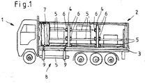
- FIG. 1 shows in side view a side wallless vehicle 1 with a tarpaulin and bow construction. 2
- the removed Spriegelbretter 5 are placed either below or next to the side wallless vehicle 1.
- this approach has the disadvantages that during storage of the Spriegelbretter 5 under the vehicle 1 this can not be moved without the Spriegelbretter 5 to run over and to damage or destroy.
- the Spriegelbretter 5 When storing the Spriegelbretter 5 next to the vehicle 1, the Spriegelbretter 5 on the one hand represent a trip hazard and on the other hand, the loading and unloading in the way and are often run over by these, causing the Spriegelbretter 5 are damaged or destroyed.
- a vehicle 1 is on the frame 3 of in Fig. 1 illustrated side wallless vehicle 1 consisting of two loops 8 device 8 for storing the Spriegelbretter 5 arranged during the loading and unloading.
- This device 8 consists of at least two fixable on the frame 3 of the side wallless vehicle 1 loops 8 for receiving the Spriegelbretter 5, wherein the fixing of each loop 8 takes place on the frame 3 via a suspension mechanism 10.
- the holding support of the Spriegelbretter 5 on the frame 3 prevents damaging the Spriegelbretter 5 and keeps them beyond ready in the immediate vicinity of the vehicle 1 for re-insertion into the Spr manaschen 6 of the vehicle body ready.
- the loops 9 themselves are preferably formed as straps of one of a textile material.
- a cut-resistant material is advantageously used to form the loops 9.
- loops 9 made of a textile material with a coating of a cut-resistant material so as to protect the loops against mechanical damage by the sprue boards 5 mounted in the loops 9.
- loops 9 are also possible to form the loops 9 not of a textile material, but as metal loops or chain rings.
- FIGS. 2 and 3 The construction of a loop 9 and of the suspension mechanism 10 for fixing the loop 9 on the frame 3 of the vehicle 1 is shown in particular in FIGS. 2 and 3.
- the suspension mechanism 10 has at least one hook 11 for connection to the frame 3 and a pivot 12 between the hook 11 and the loop 9.
- the use of the swivel joint 12 between the hook 11 and the loop 9 ensures that the respective loop 9 can be simply and quickly aligned during insertion of the first bowing board 5 in such a way that the bowling board 5 can be slid lengthwise into the loop 9.
- the swivel joint 12 is advantageously designed as a swivel 13. By the use of the rotating vortex 13, it is prevented that shearing loads can act on the suspension, in particular the hook 11 fixed to the frame 3.
- the fixing of the loops 9 on the frame 3 of the vehicle 1 via the hooks 11 of the suspension mechanism 10 takes place, for example, in the openings formed in the frame 3, in which otherwise the straps for securing the charge can be fixed.
- a web 14 running in the direction of the loop circumference is arranged.
- This web 14 serves on the one hand to prevent the load at the point of action of the suspension mechanism 10 on the loop 9 acts only selectively on the loop 9 and so could cause a tearing of the loop 9.
- the other is the jetty 14 but also to open the loop 9, whereby the insertion of the Spriegelbretter 5 is facilitated in the loop 9.
- the length of the loop circumference is variably adjustable.
- FIG. 4 shows schematically the sequence of use of the above-described device 8 for supporting the Spriegelbretter 5. Since the loops 9 are rotatably mounted on the pivot joints 12 on the frame 3 of the vehicle 1, it is recommended, especially when inserting the first Spriegelbretts 5 to proceed in the loops 8 of the device 8 as shown.
- the person supporting the bowling board 5 turns laterally next to the two loops 9 of the device 8 suspended from the frame 3 of the vehicle 1, that a loop 9 is arranged to its left side and the other loop 9 to its right side. Now the to be inserted bowing board 5 is first threaded in the direction of the arrow P1 in the left loop 9 (or the right loop 9).
- the hoisting board 5 is threaded in the direction of the arrow P2 into the right loop 9 (or the left loop 9).
- This described procedure is easier, in particular when threading the first bowing board 5 into the loops 9, than the insertion of the long bowling boards 5 from the rear or front through both loops 9.
- a device 8 constructed as described above for the storage of sprue boards 5 is characterized in that it allows safe storage of the Spriegelbretter 5 when loading and unloading a vehicle 1 or vehicle trailer and accelerates the loading and unloading, since the Spriegelbretter 5 not have to be pushed back and forth to avoid being in the way.
Abstract
Die Erfindung betrifft eine Vorrichtung (8) zur Lagerung von Spriegelbrettern (5) beim Beladen und Entladen von seitenwandlosen Fahrzeugen (1) und seitenwandlosen Fahrzeuganhängern mit Spriegel- und Planeaufbauten (2). Eine Vorrichtung zur Lagerung von Spriegelbrettern (5), die ein gefahrloses Lagern der Spriegelbretter (5) beim Be- und Entladen ermöglicht, ist erfindungsgemäß gekennzeichnet durch mindestens zwei an einem Rahmen (3) des seitenwandlosen Fahrzeugs (1) oder seitenwandlosen Fahrzeuganhängers festlegbare Schlaufen (9) zur Aufnahme der Spriegelbretter (5), wobei das Festlegen einer jeden Schlaufen (9) am Rahmen (3) über einen Aufhängemechanismus (10) erfolgt.The invention relates to a device (8) for the storage of Spriegelbrettern (5) during loading and unloading of side wall-mounted vehicles (1) and side wall-mounted vehicle trailers with Spriegel- and plan structures (2). A device for mounting of Spriegelbrettern (5), which allows safe storage of the Spriegelbretter (5) during loading and unloading, according to the invention characterized by at least two on a frame (3) of the side wallless vehicle (1) or side wallless vehicle trailer lockable loops ( 9) for receiving the Spriegelbretter (5), wherein the fixing of each loop (9) on the frame (3) via a suspension mechanism (10).
Description
Die Erfindung betrifft eine Vorrichtung zur Lagerung von Spriegelbrettern beim Beladen und Entladen von seitenwandlosen Fahrzeugen und seitenwandlosen Fahrzeuganhängern mit Spriegel- und Planeaufbauten.The invention relates to a device for the storage of Spriegelbrettern during loading and unloading of side wall-mounted vehicles and side wall-mounted vehicle trailers with Spriegel- and plan structures.
Seitenwandlose Fahrzeuge und seitenwandlose Fahrzeuganhänger mit Plane- und Sprieglaufbauten weisen keine festen seitlichen Bordwände auf. Statt dessen werden die Seiten durch entnehmbare senkrechte Rungen und die Rungen miteinander verbindende horizontale Spriegelbretter, die in Spriegeltaschen an den Rungen gelagert sind, sowie die darüber gespannte Plane gebildet. Die Spriegelbretter bestehen aus Holz oder Aluminium und wiegen bei einer Länge von bis zu 3 Meter 3 Kilogramm und mehr.Sidewallless vehicles and side wallless vehicle trailers with tarpaulin and Sprieglaufbauten have no fixed lateral side walls. Instead, the sides are formed by removable vertical stakes and the stanchions interconnecting horizontal Spriegelbretter, which are stored in buckets on the stakes, as well as over the tarred tarpaulin. The Spriegelbretter consist of wood or aluminum and weigh with a length of up to 3
Um das Fahrzeug bzw. den Fahrzeuganhänger auch von der Seite beladen und entladen zu können, müssen nach den Zurückziehen der Plane die Spriegelbretter aus ihrer Lagerung in den Spriegeltaschen entfernt werden.In order to be able to load and unload the vehicle or the vehicle trailer from the side as well, after retracting the tarpaulin, the aerofoil boards must be removed from their storage in the spray bags.
In der Praxis werden die entnommenen Bretter entweder unter oder neben das seitenwandlose Fahrzeuganhänger gelegt. Diese Vorgehensweise weist jedoch die Nachteile auf, dass bei der Lagerung unter dem Fahrzeug dieses nicht bewegt werden kann, ohne die Spriegelbretter zu überfahren und so zu beschädigen bzw. zu zerstören. Bei der Lagerung neben dem Fahrzeug stellen die Spriegelbretter einerseits eine Stolperfalle dar und liegen andererseits den Be- und Entladestaplern im Weg und werden von diesen häufig überfahren, wodurch die Spriegelbretter beschädigt oder zerstört werden.In practice, the removed boards are placed either under or beside the side wallless vehicle trailer. However, this approach has the disadvantages that when stored under the vehicle this can not be moved without running over the Spriegelbretter and so damaging or destroying. When stored next to the vehicle the Spriegelbretter represent on the one hand a trip hazard and on the other hand, the loading and unloading in the way and are often run over by these, causing the Spriegelbretter be damaged or destroyed.
Aus der
Davon ausgehend liegt der Erfindung die Aufgabe zugrunde, eine Vorrichtung zum Lagern von Spriegelbrettern zu schaffen, die ein gefahrloses Lagern der Spriegelbretter beim Be- und Entladen ermöglicht ermöglicht.On this basis, the invention is based on the object to provide a device for storing of a bow, which allows permits safe storage of the Hoop boards when loading and unloading.
Die Lösung dieser Aufgabenstellung ist erfindungsgemäß gekennzeichnet durch mindestens zwei an einem Rahmen des seitenwandlosen Fahrzeugs oder seitenwandlosen Fahrzeuganhängers festlegbare Schlaufen zur Aufnahme der Spriegelbretter, wobei das Festlegen einer jeden Schlaufen am Rahmen über einen Aufhängemechanismus erfolgt.The solution to this problem is inventively characterized by at least two attachable to a frame of the side wall-mounted vehicle or side-mounted vehicle trailer loops for receiving the Spriegelbretter, wherein the setting of each loop on the frame via a suspension mechanism.
Durch die Verwendung der vorzugsweise paarweise zu verwendenden Schlaufen, die am Rahmen des seitenwandlosen Fahrzeugs oder seitenwandlosen Fahrzeuganhängers festlegbar sind, ist es erstmalig möglich, die vom Aufbau abgenommenen Spriegelbretter so zu lagern, dass diese einerseits nicht die Bewegung des seitenwandlosen Fahrzeugs bzw. seitenwandlosen Fahrzeuganhängers einschränken und andererseits weder den mit der Be- und/oder Entladung befassten Personen noch den Be- und Entladestaplern im Weg liegen.By using the preferably pairs to use loops, which can be fixed to the frame of the side wall-mounted vehicle or side wall-mounted vehicle trailer, it is possible for the first time to remove the structure removed from the Spriegelbretter so that on the one hand does not restrict the movement of the side wall-mounted vehicle or side wall-mounted vehicle trailer on the other hand, neither the persons involved in the loading and / or unloading nor the loading and unloading trucks are in the way.
Die haltende Lagerung der Spriegelbretter am Fahrzeugrahmen verhindert ein Beschädigen der Spriegelbretter und hält diese darüber hinaus in unmittelbarer Nähe des Fahrzeugs bzw. Fahrzeuganhängers zum Wiedereinsetzen in die Spriegeltaschen des Fahrzeugaufbaus bereit.The holding support of the Spriegelbretter on the vehicle frame prevents damage to the Spriegelbretter and keeps them also in the immediate vicinity of the vehicle or vehicle trailer ready for re-insertion into the Sprießaschen the vehicle body.
Gemäß einer bevorzugten Ausführungsform der Erfindung wird vorgeschlagen, die Schlaufen als Gurte aus einem textilen Material ausgebildet sind, wobei das textile Material vorzugsweise schnittfest ausgebildet ist. Die Ausbildung der Gurte stellt eine besonders einfache und günstige Art zur Bereitstellung der Schlaufen dar. Die Schnittfestigkeit des Schlaufenmaterials ist vorteilhaft, da insbesondere die aus Aluminium gefertigten Spriegelbretter häufig sehr scharfkantig ausgebildet sind.According to a preferred embodiment of the invention, it is proposed that the loops are designed as straps made of a textile material, wherein the textile material is preferably designed cut resistant. The training of straps provides a particularly simple and inexpensive way to provide the loops. The cut resistance of the loop material is advantageous, since in particular made of aluminum Spriegelbretter are often very sharp-edged.
Mit einer alternativen Ausführungsform zur Ausbildung der aus einem textilen Material gefertigten Schlaufen wird mit der Erfindung vorgeschlagen, dass die textilen Schlaufen mit einem Überzug aus einem schnittfesten Material überzogen sind.With an alternative embodiment for forming the loops made of a textile material is proposed with the invention that the textile loops are coated with a coating of a cut-resistant material.
Alternativ zur Ausbildung der Schlaufen als Gurte aus einem textilen Material ist es selbstverständlich auch möglich, die Schlaufen als Metallschlaufen oder als Kettenring auszubilden.Alternatively to the formation of the loops as straps made of a textile material, it is of course also possible to form the loops as metal loops or as a chain ring.
Zur Ausbildung des Aufhängemechanismus wird gemäß einer praktischen Ausführungsform der Erfindung vorgeschlagen, dass der Aufhängemechanismus mindestens einen Haken zum Verbinden mit dem Rahmen sowie ein Drehgelenk zwischen dem Haken und der Schlaufe umfasst. Die Verwendung des Drehgelenks zwischen Haken und Schlaufe stellt sicher, dass die jeweilige Schlaufe beim Einschieben des ersten Spriegelbretts einfach und schnell ausgerichtet werden kann.To form the suspension mechanism, according to a practical embodiment of the invention, it is proposed that the suspension mechanism comprise at least one hook for connection to the frame and a hinge between the hook and the loop. The use of the hinge between hook and loop ensures that the respective loop can be easily and quickly aligned when inserting the first bow.
Weiterhin wird mit der Erfindung vorgeschlagen, dass das Drehgelenk vorteilhafterweise als Drehwirbel ausgebildet ist. Durch die Verwendung eines Drehwirbels wird verhindert, dass Scherbelastungen auf die Aufhängung, insbesondere den am Fahrzeugrahmen festgelegten Haken, einwirken können.Furthermore, it is proposed with the invention that the rotary joint is advantageously designed as a swivel. The use of a swivel prevents shearing loads from acting on the suspension, in particular the hook fixed to the vehicle frame.
Schließlich wird mit der Erfindung vorgeschlagen, dass die Länge des Schlaufenumfangs variabel einstellbar ist, um die Vorrichtung an die Aufnahme von mehr oder weniger Spriegelbrettern sowie verschiedene Rahmenhöhen der Fahrzeuge bzw. Fahrzeuganhänger anpassen zu können.Finally, it is proposed with the invention that the length of the loop circumference is variably adjustable in order to adapt the device to the reception of more or less Spriegelbrettern and different frame heights of vehicles or vehicle trailers.
Weitere Merkmale und Vorteile der Erfindung ergeben sich anhand der zugehörigen Zeichnungen, in denen ein Ausführungsbeispiel einer erfindungsgemäßen Vorrichtung zur Lagerung von Spriegelbrettern nur beispielhaft dargestellt ist, ohne die Erfindung auf dieses Ausführungsbeispiel zu beschränken. In den Zeichnungen zeigt:
- Fig. 1
- eine schematische Seitenansicht eines seitenwandlosen Fahrzeugs mit Plane- und Spriegelaufbau, an dem eine erfindungsgemäße Vorrichtung zur Lagerung von Spriegelbrettern befestigt ist,
- Fig. 2
- eine vergrößerte Seitensicht einer Schlaufe einer erfindungsgemäßen Vorrichtung;
- Fig. 3
- eine vergrößerte Ansicht des Details III gemäß Fig. 2 und
- Fig. 4
- eine schematische Ablaufskizze zur Verwendung der erfindungsgemäßen Vorrichtung.
- Fig. 1
- a schematic side view of a side wallless vehicle with tarpaulin and bow construction, on which a device according to the invention for the storage of Spriegelbrettern is attached,
- Fig. 2
- an enlarged side view of a loop of a device according to the invention;
- Fig. 3
- an enlarged view of the detail III of FIG. 2 and
- Fig. 4
- a schematic flow diagram for use of the device according to the invention.
Die Abbildung
Seitenwandlose Fahrzeuge 1 und seitenwandlose Fahrzeuganhänger mit Plane- und Sprieglaufbauten 2 weisen keine festen seitlichen Bordwände auf. Statt dessen werden die Seiten durch in einem Rahmen 3 des Fahrzeugs 1 festlegbare senkrechte Rungen 4 und die Rungen 4 miteinander verbindende horizontale Spriegelbretter 5, die in Spriegeltaschen 6 an den Rungen 4 gelagert sind, sowie die darüber gespannte Plane 7 gebildet.Sidewallless vehicles 1 and side wallless vehicle trailers with tarpaulin and
Seitenwandlose Fahrzeuge 1 und seitenwandlose Fahrzeuganhänger mit Plane- und Spriegelaufbau 2 können neben den klassischen LKW und LKW-Anhängern auch Kleinlaster und Eisenbahnwagen mit entsprechendem Plane- und Spriegelaufbau 2 sein.Seitenwandlose vehicles 1 and side wall-mounted vehicle trailers with tarpaulin and
Um das Fahrzeug 1 auch von der Seite beladen und entladen zu können, müssen nach den Zurückziehen der Plane 7 die Spriegelbretter 5 aus ihrer Lagerung in den Spriegeltaschen 6 der Rungen 4 entfernt werden.In order to be able to load and unload the vehicle 1 also from the side, after retracting the
In der Praxis werden die entnommenen Spriegelbretter 5 entweder unter oder neben das seitenwandlose Fahrzeug 1 gelegt. Diese Vorgehensweise weist jedoch die Nachteile auf, dass bei der Lagerung der Spriegelbretter 5 unter dem Fahrzeug 1 dieses nicht bewegt werden kann, ohne die Spriegelbretter 5 zu überfahren und so zu beschädigen bzw. zu zerstören. Bei der Lagerung der Spriegelbretter 5 neben dem Fahrzeug 1 stellen die Spriegelbretter 5 einerseits eine Stolperfalle dar und liegen andererseits den Be- und Entladestaplern im Weg und werden von diesen häufig überfahren, wodurch die Spriegelbretter 5 beschädigt oder zerstört werden.In practice, the removed Spriegelbretter 5 are placed either below or next to the side wallless vehicle 1. However, this approach has the disadvantages that during storage of the Spriegelbretter 5 under the vehicle 1 this can not be moved without the
Zur Vermeidung dieser voranstehend beschriebenen Nachteile beim Be- und Entladen eines Fahrzeugs 1 ist am Rahmen 3 des in
Diese Vorrichtung 8 besteht aus mindestens zwei an dem Rahmen 3 des seitenwandlosen Fahrzeugs 1 festlegbaren Schlaufen 8 zur Aufnahme der Spriegelbretter 5, wobei das Festlegen einer jeden Schlaufen 8 am Rahmen 3 über einen Aufhängemechanismus 10 erfolgt.This
Durch die Verwendung der vorzugsweise paarweise zu verwendenden Schlaufen 9, die am Rahmen 3 des Fahrzeugs 1 festlegbar sind, ist es möglich, die vom Aufbau abgenommenen Spriegelbretter 5 so zu lagern, dass diese einerseits nicht die Bewegung des Fahrzeugs 1 einschränken und andererseits weder den mit der Be- und/oder Entladung befassten Personen noch den Be- und Entladestaplern im Weg liegen.By using the preferably pairs to use
Die haltende Lagerung der Spriegelbretter 5 am Rahmen 3 verhindert ein Beschädigen der Spriegelbretter 5 und hält diese darüber hinaus in unmittelbarer Nähe des Fahrzeugs 1 zum Wiedereinsetzen in die Spriegeltaschen 6 des Fahrzeugaufbaus bereit.The holding support of the Spriegelbretter 5 on the
Die Schlaufen 9 selbst sind vorzugsweise als Gurte aus einem aus einem textilen Material ausgebildet. Um ein Beschädigen des Materials der Schlaufen 9 insbesondere bei den aus Aluminium bestehenden Spriegelbrettern 5 zu vermeiden, wird zur Ausbildung der Schlaufen 9 vorteilhafterweise ein schnittfestes Material verwendet.The
Alternativ besteht die Möglichkeit, die aus einem textilen Material gefertigten Schlaufen 9 mit einem Überzug aus einem schnittfesten Material zu überziehen, um so die Schlaufen vor mechanischer Beschädigung durch die in den Schlaufen 9 gelagerten Spriegelbretter 5 zu schützen.Alternatively, it is possible to coat the
Selbstverständlich ist es auch möglich, die Schlaufen 9 nicht aus einem textilen Material, sondern als Metallschlaufen oder als Kettenringe auszubilden.Of course, it is also possible to form the
Der Aufbau einer Schlaufe 9 sowie des Aufhängemechanismus 10 zum Festlegen der Schlaufe 9 am Rahmen 3 des Fahrzeugs 1 ist insbesondere den Abbildungen Fig. 2 und 3 zu entnehmen.The construction of a
Der Aufhängemechanismus 10 weist mindestens einen Haken 11 zum Verbinden mit dem Rahmen 3 sowie ein Drehgelenk 12 zwischen dem Haken 11 und der Schlaufe 9 auf. Die Verwendung des Drehgelenks 12 zwischen Haken 11 und Schlaufe 9 stellt sicher, dass die jeweilige Schlaufe 9 beim Einschieben des ersten Spriegelbretts 5 einfach und schnell so ausgerichtet werden kann, dass das Spriegelbrett 5 der Länge nach in die Schlaufe 9 geschoben werden kann.The suspension mechanism 10 has at least one hook 11 for connection to the
Das Drehgelenk 12 ist vorteilhafterweise als Drehwirbel 13 ausgebildet. Durch die Verwendung des Drehwirbels 13 wird verhindert, dass Scherbelastungen auf die Aufhängung, insbesondere den am Rahmen 3 festgelegten Haken 11, einwirken können.The swivel joint 12 is advantageously designed as a swivel 13. By the use of the rotating vortex 13, it is prevented that shearing loads can act on the suspension, in particular the hook 11 fixed to the
Das Festlegen der Schlaufen 9 am Rahmen 3 des Fahrzeugs 1 über die Haken 11 des Aufhängemechanismus 10 erfolgt beispielsweise in den im Rahmen 3 ausgebildeten Öffnungen, in denen sonst die Spanngurte zum Verzurren der Ladung festlegbar sind.The fixing of the
Wie aus Fig. 2 ersichtlich, ist im Bereich der Befestigung des Aufhängemechanismus 10 an der Schlaufe 9 auf der Innenseite der Schlaufe 9 ein in Richtung des Schlaufenumfangs verlaufender Steg 14 angeordnet. Dieser Steg 14 dient zum einen dazu zu verhindern, dass die Last im Angriffspunkt des Aufhängemechanismus 10 an der Schlaufe 9 nur punktuell auf die Schlaufe 9 wirkt und so ein Ausreißen der Schlaufe 9 bewirken könnte. Zum anderen dient der Steg 14 aber auch dazu, die Schlaufe 9 zu öffnen, wodurch das Einfügen der Spriegelbretter 5 in die Schlaufe 9 erleichtert wird.As can be seen from FIG. 2, in the region of attachment of the suspension mechanism 10 to the
Um die Vorrichtung 8 an die Aufnahme von mehr oder weniger Spriegelbrettern 5 sowie verschiedene Rahmenhöhen der Fahrzeuge 1 bzw. Fahrzeuganhänger anpassen zu können, ist die Länge des Schlaufenumfangs variabel einstellbar.In order to adapt the
Die Abbildung Fig. 4 zeigt schematisch den Ablauf der Verwendung der voranstehend beschriebenen Vorrichtung 8 zur Lagerung der Spriegelbretter 5. Da die Schlaufen 9 über die Drehgelenke 12 verdrehbar am Rahmen 3 des Fahrzeugs 1 gelagert sind, empfiehlt es sich, insbesondere beim Einfügen des ersten Spriegelbretts 5 in die Schlaufen 8 der Vorrichtung 8 wie dargestellt vorzugehen.The figure Fig. 4 shows schematically the sequence of use of the above-described
Im ersten Schritt stellt sich die das Spriegelbrett 5 tragende Person seitlich so neben die beiden am Rahmen 3 des Fahrzeugs 1 aufgehängten Schlaufen 9 der Vorrichtung 8, dass eine Schlaufe 9 zu seiner linken Seite und die andere Schlaufe 9 zu seiner rechten Seite angeordnet ist. Jetzt wird das einzusetzende Spriegelbrett 5 in Richtung des Pfeils P1 zuerst in die linke Schlaufe 9 (oder die rechte Schlaufe 9) eingefädelt.In the first step, the person supporting the
Anschließend im zweiten Schritt wird das Spriegelbrett 5 in Richtung des Pfeils P2 in die rechte Schlaufe 9 (oder die linke Schlaufe 9) eingefädelt.Subsequently, in the second step, the hoisting
Diese beschriebene Vorgehensweise ist insbesondere beim Einfädeln des ersten Spriegelbretts 5 in die Schlaufen 9 einfacher als das Einschieben der langen Spriegelbretter 5 von hinten oder vorne durch beide Schlaufen 9.This described procedure is easier, in particular when threading the
Eine wie voranstehend beschrieben aufgebaute Vorrichtung 8 zur Lagerung von Spriegelbrettern 5 zeichnet sich dadurch aus, dass diese ein gefahrloses Lagern der Spriegelbretter 5 beim Be- und Entladen eines Fahrzeugs 1 bzw. Fahrzeuganhängers ermöglicht und den Be- und Entladevorgang beschleunigt, da die Spriegelbretter 5 nicht hin- und hergeschoben werden müssen, um nicht im Wege zu liegen.A
- 11
- seitenwandloses Fahrzeugside wall-less vehicle
- 22
- Plane- und SpriegelaufbauTarpaulin and bow construction
- 33
- Rahmenframe
- 44
- Rungestake
- 55
- SpriegelbrettSpriegelbrett
- 66
- SpriegeltascheSpriegeltasche
- 77
- PlanePlans
- 88th
- Vorrichtungdevice
- 99
- Schlaufeloop
- 1010
- Aufhängemechanismussuspension mechanism
- 1111
- Hakenhook
- 1212
- Drehgelenkswivel
- 1313
- Drehwirbelswivel
- 1414
- Stegweb
- P1P1
- Pfeilarrow
- P2P2
- Pfeilarrow
Claims (7)
gekennzeichnet durch
mindestens zwei an einem Rahmen (3) des seitenwandlosen Fahrzeugs (1) oder seitenwandlosen Fahrzeuganhängers festlegbare Schlaufen (9) zur Aufnahme der Spriegelbretter (5), wobei das Festlegen einer jeden Schlaufen (9) am Rahmen (3) über einen Aufhängemechanismus (10) erfolgt.Device for the storage of sprue boards during loading and unloading of side-wall-mounted vehicles (1) and side-wall-mounted vehicle trailers with bow and tarpaulin structures (2),
marked by
at least two loops (9), which can be fixed on a frame (3) of the side-wall-mounted vehicle (1) or side-wall-mounted vehicle trailer, for receiving the bowing boards (5), wherein the fixing of each loop (9) to the frame (3) is effected by means of a suspension mechanism (10) he follows.
Applications Claiming Priority (1)
| Application Number | Priority Date | Filing Date | Title |
|---|---|---|---|
| DE102017009701.1A DE102017009701B4 (en) | 2017-10-18 | 2017-10-18 | Device for storing bow boards |
Publications (1)
| Publication Number | Publication Date |
|---|---|
| EP3473531A1 true EP3473531A1 (en) | 2019-04-24 |
Family
ID=63914923
Family Applications (1)
| Application Number | Title | Priority Date | Filing Date |
|---|---|---|---|
| EP18201316.9A Withdrawn EP3473531A1 (en) | 2017-10-18 | 2018-10-18 | Device for holding sail boards |
Country Status (2)
| Country | Link |
|---|---|
| EP (1) | EP3473531A1 (en) |
| DE (1) | DE102017009701B4 (en) |
Citations (4)
| Publication number | Priority date | Publication date | Assignee | Title |
|---|---|---|---|---|
| GB1498655A (en) * | 1976-04-23 | 1978-01-25 | Chrysler Uk | Attachment devices |
| US5325568A (en) * | 1993-06-21 | 1994-07-05 | Ronald Bruhm | Tie-down device combining a looped strap and a snubbing clinch |
| DE10106920A1 (en) * | 2001-02-15 | 2002-09-19 | Bayerische Motoren Werke Ag | Securing device for loads on vehicle seats comprises luggage strap with belt tongue locking into lock of seat belt system and with socket to receive locking part at other end of strap |
| US20160375818A1 (en) * | 2015-06-24 | 2016-12-29 | Ancra International Llc | Assistance strap for access to cargo container |
Family Cites Families (3)
| Publication number | Priority date | Publication date | Assignee | Title |
|---|---|---|---|---|
| DE7904408U1 (en) * | 1979-11-15 | Westfalia-Werke Franz Knoebel & Soehne Kg, 4840 Rheda-Wiedenbrueck | Trailer with a device for fastening tarpaulins | |
| DE7314786U (en) * | 1973-04-18 | 1973-08-09 | Schenk R Fahrzeugfabrik | Structure for trucks and trailers |
| EP2184221B2 (en) * | 2008-11-10 | 2016-09-14 | F. HESTERBERG & SÖHNE GmbH & Co. KG | Bar holder for commercial vehicle trailers |
-
2017
- 2017-10-18 DE DE102017009701.1A patent/DE102017009701B4/en active Active
-
2018
- 2018-10-18 EP EP18201316.9A patent/EP3473531A1/en not_active Withdrawn
Patent Citations (4)
| Publication number | Priority date | Publication date | Assignee | Title |
|---|---|---|---|---|
| GB1498655A (en) * | 1976-04-23 | 1978-01-25 | Chrysler Uk | Attachment devices |
| US5325568A (en) * | 1993-06-21 | 1994-07-05 | Ronald Bruhm | Tie-down device combining a looped strap and a snubbing clinch |
| DE10106920A1 (en) * | 2001-02-15 | 2002-09-19 | Bayerische Motoren Werke Ag | Securing device for loads on vehicle seats comprises luggage strap with belt tongue locking into lock of seat belt system and with socket to receive locking part at other end of strap |
| US20160375818A1 (en) * | 2015-06-24 | 2016-12-29 | Ancra International Llc | Assistance strap for access to cargo container |
Also Published As
| Publication number | Publication date |
|---|---|
| DE102017009701B4 (en) | 2021-04-15 |
| DE102017009701A1 (en) | 2019-04-18 |
Similar Documents
| Publication | Publication Date | Title |
|---|---|---|
| EP2708731B1 (en) | Method and device for transporting a rotor blade of a wind energy plant | |
| DE1680107C3 (en) | Device for vehicles for loading and unloading loads | |
| WO2018202608A1 (en) | Flow-guide panel | |
| EP3473531A1 (en) | Device for holding sail boards | |
| DE202022001426U1 (en) | Auxiliary device for handling lashing straps | |
| DE2651561A1 (en) | Spring loaded bottom discharge skip - partly self-closing double flaps shut in succession with overlap for sealing | |
| DE10054656C2 (en) | Collapsible warning triangle | |
| DE102016116045B4 (en) | Mobile observation stand | |
| DE102011110934A1 (en) | Transportation container for transporting equipment pieces for submarine, has rollers extended from lower side of container by through-holes, which are formed at bottom of container, and frame structure provided with rectangular frames | |
| EP3587181B1 (en) | Transport vehicle | |
| DE867496C (en) | Device for storing ladders and other equipment on the roof of fire engines | |
| DE2319474A1 (en) | SCAFFOLDING TO PERFORM WORK ON AN OVERHANGING SHIP WALL | |
| DE4323983C1 (en) | Transport device for cash boxes | |
| DE1087459B (en) | Transport, loading and towing equipment for motor vehicles | |
| DE202017103647U1 (en) | Device for storing and / or transporting elements, in particular for the construction industry | |
| DE450318C (en) | Device for reloading fallen goods | |
| DE1959316U (en) | GUIDANCE DEVICE PROVIDED ON A CRANE CONCRETE BUCKET. | |
| DE1921472C3 (en) | Device for coupling containers or the like | |
| DE3026444A1 (en) | Remote operated canvas side cover for lorry - has series of pull lines pulley linked to end of lorry | |
| DE102008004173A1 (en) | Tipper has two arms, which are arranged parallel to each other and pivoted in rear area of vehicle-storage area and swiveling around axes running parallel to rear boundary, and safety device connects loading base with connecting unit | |
| DE7001334U (en) | DEVICE FOR LOCKING IN PARTICULAR ROLLER CONTAINERS ON ROAD VEHICLES | |
| DE1285340B (en) | Semi-trailers, especially for transporting prefabricated components for houses | |
| DE8104914U1 (en) | AGRICULTURAL TRANSPORT VEHICLE WITH FOLD-OUT BOARDS | |
| DE1868041U (en) | DEVICE FOR RELEASABLE COUPLING OF A LIFTING CRANE TO A TRUCK TRUCK OD. DGL. | |
| DE1222220B (en) | Hydraulic lifting device in the form of a reciprocating parallel crank gear |
Legal Events
| Date | Code | Title | Description |
|---|---|---|---|
| PUAI | Public reference made under article 153(3) epc to a published international application that has entered the european phase |
Free format text: ORIGINAL CODE: 0009012 |
|
| AK | Designated contracting states |
Kind code of ref document: A1 Designated state(s): AL AT BE BG CH CY CZ DE DK EE ES FI FR GB GR HR HU IE IS IT LI LT LU LV MC MK MT NL NO PL PT RO RS SE SI SK SM TR |
|
| AX | Request for extension of the european patent |
Extension state: BA ME |
|
| STAA | Information on the status of an ep patent application or granted ep patent |
Free format text: STATUS: THE APPLICATION IS DEEMED TO BE WITHDRAWN |
|
| 18D | Application deemed to be withdrawn |
Effective date: 20191025 |