EP3473153A1 - Aspirateur et procédé de commande d'un moteur destiné à une brosse de l'aspirateur - Google Patents
Aspirateur et procédé de commande d'un moteur destiné à une brosse de l'aspirateur Download PDFInfo
- Publication number
- EP3473153A1 EP3473153A1 EP18200242.8A EP18200242A EP3473153A1 EP 3473153 A1 EP3473153 A1 EP 3473153A1 EP 18200242 A EP18200242 A EP 18200242A EP 3473153 A1 EP3473153 A1 EP 3473153A1
- Authority
- EP
- European Patent Office
- Prior art keywords
- duty cycle
- vacuum cleaner
- electrical parameter
- pwm duty
- brush
- Prior art date
- Legal status (The legal status is an assumption and is not a legal conclusion. Google has not performed a legal analysis and makes no representation as to the accuracy of the status listed.)
- Granted
Links
- 238000000034 method Methods 0.000 title claims abstract description 18
- 238000004140 cleaning Methods 0.000 claims abstract description 14
- 238000012545 processing Methods 0.000 claims description 8
- 230000003247 decreasing effect Effects 0.000 claims description 7
- 230000004044 response Effects 0.000 claims description 2
- 230000006870 function Effects 0.000 description 4
- 238000010276 construction Methods 0.000 description 3
- 230000007423 decrease Effects 0.000 description 3
- 238000005259 measurement Methods 0.000 description 3
- 238000010586 diagram Methods 0.000 description 2
- 230000009471 action Effects 0.000 description 1
- 230000003213 activating effect Effects 0.000 description 1
- 239000000654 additive Substances 0.000 description 1
- 230000000996 additive effect Effects 0.000 description 1
- 238000013459 approach Methods 0.000 description 1
- 230000033228 biological regulation Effects 0.000 description 1
- 239000003990 capacitor Substances 0.000 description 1
- 238000004891 communication Methods 0.000 description 1
- 230000003750 conditioning effect Effects 0.000 description 1
- 230000003287 optical effect Effects 0.000 description 1
- 230000008569 process Effects 0.000 description 1
Images


Classifications
-
- A—HUMAN NECESSITIES
- A47—FURNITURE; DOMESTIC ARTICLES OR APPLIANCES; COFFEE MILLS; SPICE MILLS; SUCTION CLEANERS IN GENERAL
- A47L—DOMESTIC WASHING OR CLEANING; SUCTION CLEANERS IN GENERAL
- A47L5/00—Structural features of suction cleaners
- A47L5/12—Structural features of suction cleaners with power-driven air-pumps or air-compressors, e.g. driven by motor vehicle engine vacuum
- A47L5/22—Structural features of suction cleaners with power-driven air-pumps or air-compressors, e.g. driven by motor vehicle engine vacuum with rotary fans
- A47L5/28—Suction cleaners with handles and nozzles fixed on the casings, e.g. wheeled suction cleaners with steering handle
- A47L5/30—Suction cleaners with handles and nozzles fixed on the casings, e.g. wheeled suction cleaners with steering handle with driven dust-loosening tools, e.g. rotating brushes
-
- A—HUMAN NECESSITIES
- A47—FURNITURE; DOMESTIC ARTICLES OR APPLIANCES; COFFEE MILLS; SPICE MILLS; SUCTION CLEANERS IN GENERAL
- A47L—DOMESTIC WASHING OR CLEANING; SUCTION CLEANERS IN GENERAL
- A47L9/00—Details or accessories of suction cleaners, e.g. mechanical means for controlling the suction or for effecting pulsating action; Storing devices specially adapted to suction cleaners or parts thereof; Carrying-vehicles specially adapted for suction cleaners
- A47L9/28—Installation of the electric equipment, e.g. adaptation or attachment to the suction cleaner; Controlling suction cleaners by electric means
- A47L9/2805—Parameters or conditions being sensed
- A47L9/2831—Motor parameters, e.g. motor load or speed
-
- A—HUMAN NECESSITIES
- A47—FURNITURE; DOMESTIC ARTICLES OR APPLIANCES; COFFEE MILLS; SPICE MILLS; SUCTION CLEANERS IN GENERAL
- A47L—DOMESTIC WASHING OR CLEANING; SUCTION CLEANERS IN GENERAL
- A47L9/00—Details or accessories of suction cleaners, e.g. mechanical means for controlling the suction or for effecting pulsating action; Storing devices specially adapted to suction cleaners or parts thereof; Carrying-vehicles specially adapted for suction cleaners
- A47L9/02—Nozzles
- A47L9/04—Nozzles with driven brushes or agitators
- A47L9/0405—Driving means for the brushes or agitators
- A47L9/0411—Driving means for the brushes or agitators driven by electric motor
-
- A—HUMAN NECESSITIES
- A47—FURNITURE; DOMESTIC ARTICLES OR APPLIANCES; COFFEE MILLS; SPICE MILLS; SUCTION CLEANERS IN GENERAL
- A47L—DOMESTIC WASHING OR CLEANING; SUCTION CLEANERS IN GENERAL
- A47L9/00—Details or accessories of suction cleaners, e.g. mechanical means for controlling the suction or for effecting pulsating action; Storing devices specially adapted to suction cleaners or parts thereof; Carrying-vehicles specially adapted for suction cleaners
- A47L9/02—Nozzles
- A47L9/04—Nozzles with driven brushes or agitators
- A47L9/0461—Dust-loosening tools, e.g. agitators, brushes
- A47L9/0466—Rotating tools
- A47L9/0477—Rolls
-
- A—HUMAN NECESSITIES
- A47—FURNITURE; DOMESTIC ARTICLES OR APPLIANCES; COFFEE MILLS; SPICE MILLS; SUCTION CLEANERS IN GENERAL
- A47L—DOMESTIC WASHING OR CLEANING; SUCTION CLEANERS IN GENERAL
- A47L9/00—Details or accessories of suction cleaners, e.g. mechanical means for controlling the suction or for effecting pulsating action; Storing devices specially adapted to suction cleaners or parts thereof; Carrying-vehicles specially adapted for suction cleaners
- A47L9/28—Installation of the electric equipment, e.g. adaptation or attachment to the suction cleaner; Controlling suction cleaners by electric means
- A47L9/2805—Parameters or conditions being sensed
- A47L9/2826—Parameters or conditions being sensed the condition of the floor
-
- A—HUMAN NECESSITIES
- A47—FURNITURE; DOMESTIC ARTICLES OR APPLIANCES; COFFEE MILLS; SPICE MILLS; SUCTION CLEANERS IN GENERAL
- A47L—DOMESTIC WASHING OR CLEANING; SUCTION CLEANERS IN GENERAL
- A47L9/00—Details or accessories of suction cleaners, e.g. mechanical means for controlling the suction or for effecting pulsating action; Storing devices specially adapted to suction cleaners or parts thereof; Carrying-vehicles specially adapted for suction cleaners
- A47L9/28—Installation of the electric equipment, e.g. adaptation or attachment to the suction cleaner; Controlling suction cleaners by electric means
- A47L9/2836—Installation of the electric equipment, e.g. adaptation or attachment to the suction cleaner; Controlling suction cleaners by electric means characterised by the parts which are controlled
- A47L9/2842—Suction motors or blowers
-
- A—HUMAN NECESSITIES
- A47—FURNITURE; DOMESTIC ARTICLES OR APPLIANCES; COFFEE MILLS; SPICE MILLS; SUCTION CLEANERS IN GENERAL
- A47L—DOMESTIC WASHING OR CLEANING; SUCTION CLEANERS IN GENERAL
- A47L9/00—Details or accessories of suction cleaners, e.g. mechanical means for controlling the suction or for effecting pulsating action; Storing devices specially adapted to suction cleaners or parts thereof; Carrying-vehicles specially adapted for suction cleaners
- A47L9/28—Installation of the electric equipment, e.g. adaptation or attachment to the suction cleaner; Controlling suction cleaners by electric means
- A47L9/2836—Installation of the electric equipment, e.g. adaptation or attachment to the suction cleaner; Controlling suction cleaners by electric means characterised by the parts which are controlled
- A47L9/2847—Surface treating elements
-
- A—HUMAN NECESSITIES
- A47—FURNITURE; DOMESTIC ARTICLES OR APPLIANCES; COFFEE MILLS; SPICE MILLS; SUCTION CLEANERS IN GENERAL
- A47L—DOMESTIC WASHING OR CLEANING; SUCTION CLEANERS IN GENERAL
- A47L9/00—Details or accessories of suction cleaners, e.g. mechanical means for controlling the suction or for effecting pulsating action; Storing devices specially adapted to suction cleaners or parts thereof; Carrying-vehicles specially adapted for suction cleaners
- A47L9/28—Installation of the electric equipment, e.g. adaptation or attachment to the suction cleaner; Controlling suction cleaners by electric means
- A47L9/2857—User input or output elements for control, e.g. buttons, switches or displays
-
- A—HUMAN NECESSITIES
- A47—FURNITURE; DOMESTIC ARTICLES OR APPLIANCES; COFFEE MILLS; SPICE MILLS; SUCTION CLEANERS IN GENERAL
- A47L—DOMESTIC WASHING OR CLEANING; SUCTION CLEANERS IN GENERAL
- A47L9/00—Details or accessories of suction cleaners, e.g. mechanical means for controlling the suction or for effecting pulsating action; Storing devices specially adapted to suction cleaners or parts thereof; Carrying-vehicles specially adapted for suction cleaners
- A47L9/28—Installation of the electric equipment, e.g. adaptation or attachment to the suction cleaner; Controlling suction cleaners by electric means
- A47L9/30—Arrangement of illuminating devices
Definitions
- the invention relates to a vacuum cleaner including a surface cleaning head having a brush and motor for operating the brush.
- Upright vacuum cleaners are typically used to clean floor surfaces, such as carpeting. Sometimes the carpeting can have a long pile height or other attribute providing a significant resistance to the brush of the vacuum cleaner.
- a vacuum cleaner in one embodiment, includes a surface cleaning head having a dirty air inlet, a brush supported by the surface cleaning head, and a control circuit to operate the vacuum cleaner.
- the control circuit includes a motor coupled to and operable to cause movement of the brush, a sensor to sense an electrical parameter related to an amount of carpet load restricting the brush, a comparator to determine whether the electrical parameter traverses a threshold indicative of an excess carpet load, and a switch controlled in response to the determination.
- the switch is controlled with a first pulse-width-modulated (PWM) duty cycle when the electrical parameter does not traverse the threshold and is controlled with a second PWM duty cycle when the electrical parameter traverses the threshold.
- the second PWM duty cycle is less than the first duty cycle.
- a vacuum cleaner providing a method of controlling a motor for a brush of a vacuum cleaner.
- the method includes controlling a current of the motor to move the brush, sensing an electrical parameter related to an amount of carpet load restricting the brush, comparing the electrical parameter with a threshold indicative of an excess carpet load, and determining a pulse width modulated (PWM) duty cycle value based on the comparison of the electrical parameter with the threshold.
- the determination includes decreasing the PWM duty cycle value when the electrical parameter traverses the threshold, and increasing the PWM duty cycle value when the electrical parameter does not traverse the threshold.
- the method further includes further controlling the current of the motor with a switch based on the PWM duty cycle value.
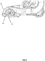
- Fig. 1 illustrates an exemplary vacuum cleaner 10.
- the vacuum cleaner 10 includes a surface cleaning head 15, a pivot assembly 20, and a canister assembly 25.
- the vacuum cleaner 10 further includes an upright handle 30.
- the vacuum cleaner 10 shown in Fig. 1 is typically referred to as an upright vacuum cleaner.
- the invention is not limited to upright vacuum cleaners, i.e., can be used in other vacuum types for example canister vacuums, stick vacuums, and robot vacuums, and the arrangement of the upright vacuum cleaner can vary from the vacuum cleaner 10 shown in Fig. 1 .
- the surface cleaning head 15 is movable along a surface 35 to be cleaned, such as a carpeted floor.
- the upright handle 30 allows a user to move the surface cleaning head 15 along the surface 35.
- the upright handle 30 is also movable relative to the surface cleaning head 15 between an upright position ( Fig. 1 ) and an inclined position.
- the surface cleaning head 15 includes a dirty air inlet 40 (shown in Fig. 2 ).
- the surface cleaning head further includes a brushroll (also referred to as a brush) 45 for agitating the surface 35 being cleaned.
- the brush 45 is driven by a brush motor 50 (shown in Fig. 3 ).
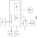
- the vacuum cleaner 10 includes other electrical components besides the brush motor 50 that are part of an appliance control circuit 55.
- the control circuit 55 further includes an appliance controller 60, a suction motor 65, a user interface, and sensors.
- the appliance controller 60 includes combinations of software and hardware that are operable to, among other things, control the operation of the vacuum 10, receive input from the sensors, receive input or provide output with the user interface, and control the motors 50 and 65.
- the appliance controller 60 includes a printed circuit board (“PCB") that is populated with a plurality of electrical and electronic components that provide, power, operational control, and protection to the vacuum 10.
- the PCB includes, for example, a processing unit 70 (e.g., a microprocessor, a microcontroller, or another suitable programmable device) and a memory 75.
- the memory 75 includes, for example, a read-only memory (“ROM”), a random access memory (“RAM”), an electrically erasable programmable read-only memory (“EEPROM”), a flash memory, or another suitable magnetic, optical, physical, or electronic memory device.
- the processing unit 70 is connected to the memory 75 and executes instructions (e.g., software) that is capable of being stored in the RAM (e.g., during execution), the ROM (e.g., on a generally permanent basis), or another non-transitory computer readable medium such as another memory or a disc. Additionally or alternatively, the memory 75 is included in the processing unit 70 (e.g., as part of a microcontroller).
- instructions e.g., software
- the RAM e.g., during execution
- the ROM e.g., on a generally permanent basis
- another non-transitory computer readable medium such as another memory or a disc.
- the memory 75 is included in the processing unit 70 (e.g., as part of a microcontroller).
- the software included in this implementation of the vacuum cleaner 10 is stored in the memory 75 of the appliance controller 60.
- the software includes, for example, firmware, program data, one or more program modules, and other executable instructions.
- the appliance controller 60 is configured to retrieve from memory and execute, among other things, instructions related to the control processes and methods described herein.
- the PCB also includes, among other things, a plurality of additional passive and active components such as resistors, capacitors, inductors, integrated circuits, and amplifiers. These components are arranged and connected to provide a plurality of electrical functions to the PCB including, among other things, signal conditioning or voltage regulation.
- the PCB and the electrical components populated on the PCB are collectively referred to as the appliance controller 60.
- the current sensor discussed below
- the current sensor for example can be mounted on the PCB and also considered part of the appliance controller 60. However, for ease of description, the current sensor will be described separately.
- the user interface is included to control the vacuum cleaner 10.
- the user interface can include a combination of digital and analog input devices to control the vacuum cleaner 10.
- the user interface can include a display 80 and a switch 85, or the like.
- the display 80 can be as simple as LEDs indicating operation of the vacuum cleaner 10, and the switch 85 can be used for activating/deactivating the vacuum cleaner 10.
- the display 80 can be mounted on a PCB with other additional passive and active components necessary for controlling the display, similar to what was discussed for the appliance controller 60, or can be mounted on the PCB for the appliance controller 60.
- the appliance controller 60 operates the brushroll motor 50 and the suction motor 65, the operation of which may be based on a floor type. For example, the appliance controller 60 may operate the suction motor 65 at a lower power on a hard floor surface to conserve energy or a higher power on a hard floor surface to increase debris pick-up. In some embodiments, the brushroll motor 50 may be operated at a lower power on certain height carpets to reduce the action of the brushroll 45 to the carpet and the force applied from the carpet to the brushroll, or carpet load, so that the vacuum cleaner 10 is less likely to stall, for example.
- the current sensor 90 (also sometimes referred to as the brushroll sensor) refers to a sensor that senses an electrical parameter related directly or indirectly to an aspect of carpet load restricting the brush.
- An exemplary parameter may be the amount of current to or through the brushroll motor 50.
- the brushroll sensor can be a tachometer for sensing a revolutions per minute (RPM) value of the brushroll 45, a tachometer for sensing an RPM value of the brushroll motor 50, an electrical sensor (e.g., the current sensor) for sensing an electrical parameter (e.g., current or voltage) of the brushroll motor 50, a torque sensor for sensing a torque parameter of the brushroll motor 50, etc. It is envisioned that the number of sensors can be greater than the single sensor shown.
- the vacuum cleaner 10 includes a current sensor 90 and an appliance controller 60 in communication with the current sensor 90.
- the current sensor 90 is configured to sense a parameter indicative of the current draw of the brushroll motor 50.
- the appliance controller 60 receives a signal from the current sensor 90 and compares the signal with a corresponding predetermined threshold.
- the appliance controller 60 includes an overload protection that will stop the brushroll motor 50 and/or vacuum cleaner operation after sensing a parameter related to an overload current (e.g., 2.3 amps in one specific example).
- a current stall indication may be provided to the user before the overload current, or failure threshold is met.
- a mechanical air bleed may be provided in the suction flow path of the vacuum cleaner 10 to provide inflow of air to the vacuum through the air bleed.
- the user is instructed to open the mechanical bleed if they are experiencing a brushroll stall event during normal use because the inflow of air to the vacuum reduces the amount of suction at the nozzle, reducing the nozzle engagement to the carpet caused by suction. Opening of the mechanical bleed reduces both the carpet load on the brushroll 45 and also the cleaning efficiency of the vacuum cleaner 10 itself.
- An alternative, or even additive, approach is to monitor the current being fed through the brushroll motor 50 and to automatically adjust via pulse width modulation (PWM) the voltage input to the brushroll motor 50.
- PWM pulse width modulation
- the current consumption of the brushroll motor 50 will also decrease as well as the speed of the brushroll 45 itself.
- the brushroll motor 50 can be automatically protected without user intervention.
- a control signal 95 is a PWM signal from the controller 60.
- the PWM signal When the PWM signal is high, current flows through the switch 100 to the brushroll motor 50.
- the PWM signal When the PWM signal is low, current is restricted by the switch 100.
- the actual average motor input voltage can be varied by adjusting the PWM signal from a maximum to a minimum duty cycle.
- the current through the brushroll 50 is monitored with the current sensor 90.
- a voltage indicative of the brushroll current is acquired from a secondary side of a transformer in a current path from the switch 85 to the brushroll motor 50.
- a voltage indicative of the brushroll current is acquired from a resistor network in a current path between the switch 85 and the brushroll motor 50.
- Firmware of the appliance controller 60 uses information gained from the current sensor signal to make adjustments to the control signal 95 to decrease the voltage at the motor as a result of increased current due to loading as a result of high pile carpet.
- a reference voltage 105 is set in the firmware.
- the reference voltage is less than the voltage associated with the overload current and selected to extend the brushroll motor run time in desired user conditions.
- the reference voltage may be a voltage providing a corresponding current that is a function of the overload current, such as 80% or 85% or 90% or other function of the overload current of the brushroll motor.
- the reference voltage is empirically determined to extend the brushroll motor run time a desired amount in the user condition.
- a reference voltage associated with 2.1 Amps is the maximum voltage that an implementation allows the PWM signal to operate with 100 percent duty.
- the vacuum cleaner 10 is turned on by the user with switch 85 and information is acquired via the current sensor 90.
- the firmware determines a difference between the current signal and the set point reference (at 110).
- the firmware uses a filter, such as a proportional, integral, and derivative (PID) filter 115, to filter the peaks and valleys out of the signal. If the current measurement is smaller than the reference voltage (at 120), the PWM duty cycle is increased to a PWM value.
- the PWM value is set to maximum voltage (e.g., 100 percent duty cycle). In other implementations, the PWM value is incremented by a value amount (e.g., 10 percent) until the maximum duty cycle is obtained.
- the PWM duty cycle typically remains at the maximum duty cycle until the voltage at the brushroll motor is equal to or larger than the reference voltage.
- the PWM value is decreased to extend the brushroll motor run time before reaching the overload current.
- the PWM value is decremented by a value amount (e.g., 10 percent) until a minimum duty cycle is obtained.
- the minimum duty cycle value may be 50 percent.
- the PWM value is decremented as a function of the reference voltage until the minimum duty cycle is obtained.
- the duty cycle is set to a first PWM duty cycle when the voltage is smaller than the reference voltage and a second, non-zero, PWM duty cycle when the voltage is larger than the reference voltage.
- the duty cycle may be 100% when the voltage associated with the brushroll current measurement is below the reference voltage and the duty cycle may be 50% when the voltage is above the reference voltage.
- the firmware wants to reduce the PWM value to be less than the minimum duty cycle value, then a current stall indication may be displayed to the user.
- the brushroll motor continues to operate at the reduced PWM duty cycle value until the current sensor signal of the brushroll motor either increases to the predetermined voltage associated with the overload current or decreases to below the reference voltage.
- the controller turns off the brushroll motor.
- the controller increases the PWM duty cycle value.
- the controller determines whether the PWM duty cycle value is less than an upper limit.
- the upper duty cycle limit may be 100%, or may be a lower limit such as 95% or 90% or any other desired predetermined limit. If the PWM duty cycle value is less than an upper limit and the measured voltage is less than the reference voltage, the controller increases the PWM duty cycle value. The controller may increase the PWM duty cycle to the upper limit or may increase the PWM duty cycle a predetermined amount.
- the invention provides a new and useful vacuum cleaner and method of controlling a motor for a brush of the vacuum cleaner.
Applications Claiming Priority (1)
| Application Number | Priority Date | Filing Date | Title |
|---|---|---|---|
| CN201710997069.XA CN109691931B (zh) | 2017-10-20 | 2017-10-20 | 真空吸尘器和控制真空吸尘器刷子的电机的方法 |
Publications (2)
| Publication Number | Publication Date |
|---|---|
| EP3473153A1 true EP3473153A1 (fr) | 2019-04-24 |
| EP3473153B1 EP3473153B1 (fr) | 2021-12-01 |
Family
ID=63857721
Family Applications (1)
| Application Number | Title | Priority Date | Filing Date |
|---|---|---|---|
| EP18200242.8A Active EP3473153B1 (fr) | 2017-10-20 | 2018-10-12 | Aspirateur et procédé de commande d'un moteur destiné à une brosse de l'aspirateur |
Country Status (3)
| Country | Link |
|---|---|
| US (2) | US11324372B2 (fr) |
| EP (1) | EP3473153B1 (fr) |
| CN (1) | CN109691931B (fr) |
Cited By (2)
| Publication number | Priority date | Publication date | Assignee | Title |
|---|---|---|---|---|
| EP3970584A1 (fr) * | 2020-09-16 | 2022-03-23 | Miele & Cie. KG | Aspirateur, de préférence aspirateur à main |
| EP4059402A1 (fr) * | 2021-03-17 | 2022-09-21 | Talentone Hong Kong Limited | Dispositif d'identification de types de plancher, dispositif d'aspiration de poussière doté de celui-ci et aspirateur l'utilisant |
Families Citing this family (4)
| Publication number | Priority date | Publication date | Assignee | Title |
|---|---|---|---|---|
| DE102019128495A1 (de) * | 2019-10-22 | 2021-04-22 | HELLA GmbH & Co. KGaA | Verfahren zum Ansteuern von Elektromotoren mit einem pulsweitenmodulierten Signal |
| CN114451807A (zh) * | 2020-11-10 | 2022-05-10 | 创科无线普通合伙 | 清扫组件、清洁设备以及用于清洁设备的方法 |
| CN116195929A (zh) * | 2021-11-30 | 2023-06-02 | 追觅创新科技(苏州)有限公司 | 清洁设备的清洁处理方法和装置、存储介质及电子装置 |
| USD1017156S1 (en) | 2022-05-09 | 2024-03-05 | Dupray Ventures Inc. | Cleaner |
Citations (4)
| Publication number | Priority date | Publication date | Assignee | Title |
|---|---|---|---|---|
| EP0467347A1 (fr) * | 1990-07-18 | 1992-01-22 | Sanyo Electric Co., Ltd. | Aspirateur à soufflante contrôlée en accord avec l'état du sol |
| WO1997007728A1 (fr) * | 1995-08-25 | 1997-03-06 | Philips Electronics N.V. | Aspirateur a commande de puissance dependant du mode de fonctionnement d'un balai electrique |
| WO2009105698A1 (fr) * | 2008-02-21 | 2009-08-27 | Euro-Pro Operating, Llc | Appareil de nettoyage de surfaces avec ajustement automatique de la vitesse des brosses |
| GB2513193A (en) * | 2013-04-19 | 2014-10-22 | Dyson Technology Ltd | Air moving appliance with on-board diagnostics |
Family Cites Families (37)
| Publication number | Priority date | Publication date | Assignee | Title |
|---|---|---|---|---|
| EP0479609A3 (en) * | 1990-10-05 | 1993-01-20 | Hitachi, Ltd. | Vacuum cleaner and control method thereof |
| JP2983658B2 (ja) * | 1991-02-14 | 1999-11-29 | 三洋電機株式会社 | 電気掃除機 |
| SE506372C2 (sv) | 1996-04-30 | 1997-12-08 | Electrolux Ab | Självgående anordning |
| GB2320419B (en) * | 1996-12-20 | 2000-08-16 | Notetry Ltd | Improved vacuum cleaner |
| GB9917232D0 (en) | 1999-07-23 | 1999-09-22 | Notetry Ltd | Method of operating a floor cleaning device |
| JP2001224544A (ja) | 2000-02-16 | 2001-08-21 | Matsushita Electric Ind Co Ltd | 電気掃除機 |
| JP3656901B2 (ja) * | 2000-08-29 | 2005-06-08 | 東芝テック株式会社 | 電気掃除機用電動送風機のインバータ制御回路を用いた駆動制御回路及びこの駆動制御回路を用いた電気掃除機 |
| DE10162181A1 (de) * | 2001-12-18 | 2003-07-10 | Bosch Gmbh Robert | Verfahren und Schaltungsanordnung zum Schutz eines Elektromotors vor Überlastung |
| US7599758B2 (en) * | 2003-09-19 | 2009-10-06 | Royal Appliance Mfg. Co. | Sensors and associated methods for controlling a vacuum cleaner |
| US7237298B2 (en) | 2003-09-19 | 2007-07-03 | Royal Appliance Mfg. Co. | Sensors and associated methods for controlling a vacuum cleaner |
| US7424766B2 (en) | 2003-09-19 | 2008-09-16 | Royal Appliance Mfg. Co. | Sensors and associated methods for controlling a vacuum cleaner |
| US20060076035A1 (en) | 2004-10-08 | 2006-04-13 | Mcgee Brian | Surface cleaning apparatus |
| US20060226799A1 (en) * | 2005-04-07 | 2006-10-12 | Chi-Chung Lin | Motor unit including a controller that protects a motor of the motor unit from burnout |
| US7823249B2 (en) | 2006-01-05 | 2010-11-02 | The Scott Fetzer Company | Motor control for a vacuum cleaner |
| JP4563427B2 (ja) | 2007-07-31 | 2010-10-13 | シャープ株式会社 | 電気掃除機 |
| CN101301186B (zh) | 2008-04-23 | 2011-12-28 | 上海中为智能机器人有限公司 | 四段式清扫机器人 |
| US8232755B2 (en) * | 2009-04-02 | 2012-07-31 | Young-Chun Jeung | Motor with circuits for protecting motor from input power outages or surges |
| GB2469126B (en) | 2009-04-04 | 2013-11-06 | Dyson Technology Ltd | Control of an electric machine |
| GB2469132B (en) | 2009-04-04 | 2014-01-29 | Dyson Technology Ltd | Control of an electric machine |
| GB2469130B (en) | 2009-04-04 | 2014-01-29 | Dyson Technology Ltd | Control system for an electric machine |
| GB2469128A (en) | 2009-04-04 | 2010-10-06 | Dyson Technology Ltd | Generating control signals for an electric machine from a position sensor |
| GB2469310B (en) | 2009-04-08 | 2013-11-06 | Ford Global Tech Llc | A seat having an armrest assembly |
| GB2471900B (en) | 2009-07-17 | 2015-01-07 | Dyson Technology Ltd | Control of an electric machine |
| US8533902B2 (en) | 2010-03-26 | 2013-09-17 | Shop Vac Corporation | Removable circuit board assembly for a vacuum |
| WO2012112468A2 (fr) | 2011-02-14 | 2012-08-23 | Shop Vac Corporation | Système et procédé de commande de la vitesse d'un moteur sur la base d'un temps d'arrêt |
| KR101995424B1 (ko) | 2012-06-13 | 2019-07-02 | 엘지전자 주식회사 | 로봇 청소기 및 그 제어방법 |
| CN202931242U (zh) | 2012-11-19 | 2013-05-08 | 萨康电子(上海)有限公司 | 一种车载吸尘器的直流电机调速电路 |
| WO2014124274A1 (fr) | 2013-02-08 | 2014-08-14 | Techtronic Floor Care Technology Limited | Système de nettoyage sans fil alimenté par batterie |
| GB2515082B (en) | 2013-06-13 | 2015-10-28 | Dyson Technology Ltd | Vacuum cleaner |
| GB2515084B (en) | 2013-06-13 | 2015-10-28 | Dyson Technology Ltd | Surface cleaning appliance |
| WO2015006341A1 (fr) | 2013-07-08 | 2015-01-15 | Thas Llc | Système de moteur cc électrique |
| US20160172933A1 (en) | 2013-07-08 | 2016-06-16 | Thas Llc | Electric dc motor system |
| EP3071087B1 (fr) | 2013-11-22 | 2023-07-26 | Techtronic Industries Co., Ltd. | Système de nettoyage sans fil alimenté par batteries |
| JP6638987B2 (ja) | 2013-12-19 | 2020-02-05 | アクチエボラゲット エレクトロルックス | 回転側面ブラシの適応速度制御 |
| US9993129B2 (en) | 2015-02-13 | 2018-06-12 | Irobot Corporation | Mobile floor-cleaning robot with floor-type detection |
| CN105030147B (zh) | 2015-09-02 | 2017-06-09 | 金日清洁设备(苏州)有限公司 | 立式吸尘器 |
| CN204862968U (zh) | 2015-09-02 | 2015-12-16 | 苏州诚河清洁设备有限公司 | 立式吸尘器 |
-
2017
- 2017-10-20 CN CN201710997069.XA patent/CN109691931B/zh active Active
-
2018
- 2018-01-24 US US15/878,501 patent/US11324372B2/en active Active
- 2018-10-12 EP EP18200242.8A patent/EP3473153B1/fr active Active
-
2022
- 2022-02-09 US US17/668,128 patent/US20220257076A1/en active Pending
Patent Citations (4)
| Publication number | Priority date | Publication date | Assignee | Title |
|---|---|---|---|---|
| EP0467347A1 (fr) * | 1990-07-18 | 1992-01-22 | Sanyo Electric Co., Ltd. | Aspirateur à soufflante contrôlée en accord avec l'état du sol |
| WO1997007728A1 (fr) * | 1995-08-25 | 1997-03-06 | Philips Electronics N.V. | Aspirateur a commande de puissance dependant du mode de fonctionnement d'un balai electrique |
| WO2009105698A1 (fr) * | 2008-02-21 | 2009-08-27 | Euro-Pro Operating, Llc | Appareil de nettoyage de surfaces avec ajustement automatique de la vitesse des brosses |
| GB2513193A (en) * | 2013-04-19 | 2014-10-22 | Dyson Technology Ltd | Air moving appliance with on-board diagnostics |
Cited By (4)
| Publication number | Priority date | Publication date | Assignee | Title |
|---|---|---|---|---|
| EP3970584A1 (fr) * | 2020-09-16 | 2022-03-23 | Miele & Cie. KG | Aspirateur, de préférence aspirateur à main |
| EP4059402A1 (fr) * | 2021-03-17 | 2022-09-21 | Talentone Hong Kong Limited | Dispositif d'identification de types de plancher, dispositif d'aspiration de poussière doté de celui-ci et aspirateur l'utilisant |
| CN115104947A (zh) * | 2021-03-17 | 2022-09-27 | 达利通香港有限公司 | 地板材质识别装置以及具有该地板材质识别装置的吸头和吸尘器 |
| US11882986B2 (en) | 2021-03-17 | 2024-01-30 | Talentone Hong Kong Limited | Floor types identifying device, dust suction device having the same, and vacuum cleaner having the same |
Also Published As
| Publication number | Publication date |
|---|---|
| EP3473153B1 (fr) | 2021-12-01 |
| CN109691931A (zh) | 2019-04-30 |
| CN109691931B (zh) | 2022-04-01 |
| US20190117031A1 (en) | 2019-04-25 |
| US11324372B2 (en) | 2022-05-10 |
| US20220257076A1 (en) | 2022-08-18 |
Similar Documents
| Publication | Publication Date | Title |
|---|---|---|
| EP3473153B1 (fr) | Aspirateur et procédé de commande d'un moteur destiné à une brosse de l'aspirateur | |
| EP2986194B1 (fr) | Aspirateur ayant un dispositif de diagnostic | |
| US7698777B2 (en) | Vacuum cleaner | |
| US11950754B2 (en) | Vacuum cleaner and vacuum cleaning system in wireless communication with a user-controlled electronic device | |
| KR930011916B1 (ko) | 전기 청소기 | |
| CN213665062U (zh) | 真空清洁器和表面处理设备 | |
| US20070050094A1 (en) | Electric vacuum cleaner | |
| US6301743B1 (en) | Vacuum cleaner with static dissipation circuit | |
| TW201722335A (zh) | 清潔設備及操作清潔設備之方法 | |
| CN111936022A (zh) | 真空吸尘器 | |
| JP4231015B2 (ja) | 電気掃除機 | |
| KR20200039348A (ko) | 청소기 및 그것의 제어방법 | |
| JP5381412B2 (ja) | 電気掃除機の被掃除面判別方法及びこれを使用した電気掃除機 | |
| JP4679308B2 (ja) | 電気掃除機 | |
| JP4785401B2 (ja) | 電気掃除機 | |
| EP4183467A1 (fr) | Nettoyage de filtre d'un dispositif de traitement d'air | |
| CN114376445B (zh) | 清扫工具以及电动吸尘器 | |
| CN214249993U (zh) | 空气净化设备 | |
| JP2024027226A (ja) | 掃除機 | |
| JP6609452B2 (ja) | 電気掃除機 | |
| JP2020179055A (ja) | 電気掃除機 | |
| CN115474865A (zh) | 地板清洁器 | |
| JP2013055973A (ja) | 電気掃除機 | |
| JP4128127B2 (ja) | 電気掃除機 | |
| WO2020163336A1 (fr) | Système de nettoyage comprenant un système pour empêcher le moteur de surchauffer et un procédé associé |
Legal Events
| Date | Code | Title | Description |
|---|---|---|---|
| PUAI | Public reference made under article 153(3) epc to a published international application that has entered the european phase |
Free format text: ORIGINAL CODE: 0009012 |
|
| STAA | Information on the status of an ep patent application or granted ep patent |
Free format text: STATUS: THE APPLICATION HAS BEEN PUBLISHED |
|
| AK | Designated contracting states |
Kind code of ref document: A1 Designated state(s): AL AT BE BG CH CY CZ DE DK EE ES FI FR GB GR HR HU IE IS IT LI LT LU LV MC MK MT NL NO PL PT RO RS SE SI SK SM TR |
|
| AX | Request for extension of the european patent |
Extension state: BA ME |
|
| STAA | Information on the status of an ep patent application or granted ep patent |
Free format text: STATUS: REQUEST FOR EXAMINATION WAS MADE |
|
| 17P | Request for examination filed |
Effective date: 20191024 |
|
| RBV | Designated contracting states (corrected) |
Designated state(s): AL AT BE BG CH CY CZ DE DK EE ES FI FR GB GR HR HU IE IS IT LI LT LU LV MC MK MT NL NO PL PT RO RS SE SI SK SM TR |
|
| STAA | Information on the status of an ep patent application or granted ep patent |
Free format text: STATUS: EXAMINATION IS IN PROGRESS |
|
| STAA | Information on the status of an ep patent application or granted ep patent |
Free format text: STATUS: EXAMINATION IS IN PROGRESS |
|
| 17Q | First examination report despatched |
Effective date: 20201002 |
|
| RAP1 | Party data changed (applicant data changed or rights of an application transferred) |
Owner name: TTI (MACAO COMMERCIAL OFFSHORE) LIMITED |
|
| RAP1 | Party data changed (applicant data changed or rights of an application transferred) |
Owner name: TECHTRONIC FLOOR CARE TECHNOLOGY LIMITED |
|
| GRAP | Despatch of communication of intention to grant a patent |
Free format text: ORIGINAL CODE: EPIDOSNIGR1 |
|
| STAA | Information on the status of an ep patent application or granted ep patent |
Free format text: STATUS: GRANT OF PATENT IS INTENDED |
|
| INTG | Intention to grant announced |
Effective date: 20210617 |
|
| GRAS | Grant fee paid |
Free format text: ORIGINAL CODE: EPIDOSNIGR3 |
|
| GRAA | (expected) grant |
Free format text: ORIGINAL CODE: 0009210 |
|
| STAA | Information on the status of an ep patent application or granted ep patent |
Free format text: STATUS: THE PATENT HAS BEEN GRANTED |
|
| AK | Designated contracting states |
Kind code of ref document: B1 Designated state(s): AL AT BE BG CH CY CZ DE DK EE ES FI FR GB GR HR HU IE IS IT LI LT LU LV MC MK MT NL NO PL PT RO RS SE SI SK SM TR |
|
| REG | Reference to a national code |
Ref country code: GB Ref legal event code: FG4D |
|
| REG | Reference to a national code |
Ref country code: AT Ref legal event code: REF Ref document number: 1450983 Country of ref document: AT Kind code of ref document: T Effective date: 20211215 Ref country code: CH Ref legal event code: EP |
|
| REG | Reference to a national code |
Ref country code: IE Ref legal event code: FG4D |
|
| REG | Reference to a national code |
Ref country code: DE Ref legal event code: R096 Ref document number: 602018027408 Country of ref document: DE |
|
| REG | Reference to a national code |
Ref country code: LT Ref legal event code: MG9D |
|
| REG | Reference to a national code |
Ref country code: NL Ref legal event code: MP Effective date: 20211201 |
|
| REG | Reference to a national code |
Ref country code: AT Ref legal event code: MK05 Ref document number: 1450983 Country of ref document: AT Kind code of ref document: T Effective date: 20211201 |
|
| PG25 | Lapsed in a contracting state [announced via postgrant information from national office to epo] |
Ref country code: RS Free format text: LAPSE BECAUSE OF FAILURE TO SUBMIT A TRANSLATION OF THE DESCRIPTION OR TO PAY THE FEE WITHIN THE PRESCRIBED TIME-LIMIT Effective date: 20211201 Ref country code: LT Free format text: LAPSE BECAUSE OF FAILURE TO SUBMIT A TRANSLATION OF THE DESCRIPTION OR TO PAY THE FEE WITHIN THE PRESCRIBED TIME-LIMIT Effective date: 20211201 Ref country code: FI Free format text: LAPSE BECAUSE OF FAILURE TO SUBMIT A TRANSLATION OF THE DESCRIPTION OR TO PAY THE FEE WITHIN THE PRESCRIBED TIME-LIMIT Effective date: 20211201 Ref country code: BG Free format text: LAPSE BECAUSE OF FAILURE TO SUBMIT A TRANSLATION OF THE DESCRIPTION OR TO PAY THE FEE WITHIN THE PRESCRIBED TIME-LIMIT Effective date: 20220301 Ref country code: AT Free format text: LAPSE BECAUSE OF FAILURE TO SUBMIT A TRANSLATION OF THE DESCRIPTION OR TO PAY THE FEE WITHIN THE PRESCRIBED TIME-LIMIT Effective date: 20211201 |
|
| PG25 | Lapsed in a contracting state [announced via postgrant information from national office to epo] |
Ref country code: SE Free format text: LAPSE BECAUSE OF FAILURE TO SUBMIT A TRANSLATION OF THE DESCRIPTION OR TO PAY THE FEE WITHIN THE PRESCRIBED TIME-LIMIT Effective date: 20211201 Ref country code: PL Free format text: LAPSE BECAUSE OF FAILURE TO SUBMIT A TRANSLATION OF THE DESCRIPTION OR TO PAY THE FEE WITHIN THE PRESCRIBED TIME-LIMIT Effective date: 20211201 Ref country code: NO Free format text: LAPSE BECAUSE OF FAILURE TO SUBMIT A TRANSLATION OF THE DESCRIPTION OR TO PAY THE FEE WITHIN THE PRESCRIBED TIME-LIMIT Effective date: 20220301 Ref country code: LV Free format text: LAPSE BECAUSE OF FAILURE TO SUBMIT A TRANSLATION OF THE DESCRIPTION OR TO PAY THE FEE WITHIN THE PRESCRIBED TIME-LIMIT Effective date: 20211201 Ref country code: HR Free format text: LAPSE BECAUSE OF FAILURE TO SUBMIT A TRANSLATION OF THE DESCRIPTION OR TO PAY THE FEE WITHIN THE PRESCRIBED TIME-LIMIT Effective date: 20211201 Ref country code: GR Free format text: LAPSE BECAUSE OF FAILURE TO SUBMIT A TRANSLATION OF THE DESCRIPTION OR TO PAY THE FEE WITHIN THE PRESCRIBED TIME-LIMIT Effective date: 20220302 Ref country code: ES Free format text: LAPSE BECAUSE OF FAILURE TO SUBMIT A TRANSLATION OF THE DESCRIPTION OR TO PAY THE FEE WITHIN THE PRESCRIBED TIME-LIMIT Effective date: 20211201 |
|
| PG25 | Lapsed in a contracting state [announced via postgrant information from national office to epo] |
Ref country code: NL Free format text: LAPSE BECAUSE OF FAILURE TO SUBMIT A TRANSLATION OF THE DESCRIPTION OR TO PAY THE FEE WITHIN THE PRESCRIBED TIME-LIMIT Effective date: 20211201 |
|
| PG25 | Lapsed in a contracting state [announced via postgrant information from national office to epo] |
Ref country code: SM Free format text: LAPSE BECAUSE OF FAILURE TO SUBMIT A TRANSLATION OF THE DESCRIPTION OR TO PAY THE FEE WITHIN THE PRESCRIBED TIME-LIMIT Effective date: 20211201 Ref country code: SK Free format text: LAPSE BECAUSE OF FAILURE TO SUBMIT A TRANSLATION OF THE DESCRIPTION OR TO PAY THE FEE WITHIN THE PRESCRIBED TIME-LIMIT Effective date: 20211201 Ref country code: RO Free format text: LAPSE BECAUSE OF FAILURE TO SUBMIT A TRANSLATION OF THE DESCRIPTION OR TO PAY THE FEE WITHIN THE PRESCRIBED TIME-LIMIT Effective date: 20211201 Ref country code: PT Free format text: LAPSE BECAUSE OF FAILURE TO SUBMIT A TRANSLATION OF THE DESCRIPTION OR TO PAY THE FEE WITHIN THE PRESCRIBED TIME-LIMIT Effective date: 20220401 Ref country code: EE Free format text: LAPSE BECAUSE OF FAILURE TO SUBMIT A TRANSLATION OF THE DESCRIPTION OR TO PAY THE FEE WITHIN THE PRESCRIBED TIME-LIMIT Effective date: 20211201 Ref country code: CZ Free format text: LAPSE BECAUSE OF FAILURE TO SUBMIT A TRANSLATION OF THE DESCRIPTION OR TO PAY THE FEE WITHIN THE PRESCRIBED TIME-LIMIT Effective date: 20211201 |
|
| REG | Reference to a national code |
Ref country code: DE Ref legal event code: R097 Ref document number: 602018027408 Country of ref document: DE |
|
| PG25 | Lapsed in a contracting state [announced via postgrant information from national office to epo] |
Ref country code: IS Free format text: LAPSE BECAUSE OF FAILURE TO SUBMIT A TRANSLATION OF THE DESCRIPTION OR TO PAY THE FEE WITHIN THE PRESCRIBED TIME-LIMIT Effective date: 20220401 |
|
| PLBE | No opposition filed within time limit |
Free format text: ORIGINAL CODE: 0009261 |
|
| STAA | Information on the status of an ep patent application or granted ep patent |
Free format text: STATUS: NO OPPOSITION FILED WITHIN TIME LIMIT |
|
| PG25 | Lapsed in a contracting state [announced via postgrant information from national office to epo] |
Ref country code: DK Free format text: LAPSE BECAUSE OF FAILURE TO SUBMIT A TRANSLATION OF THE DESCRIPTION OR TO PAY THE FEE WITHIN THE PRESCRIBED TIME-LIMIT Effective date: 20211201 Ref country code: AL Free format text: LAPSE BECAUSE OF FAILURE TO SUBMIT A TRANSLATION OF THE DESCRIPTION OR TO PAY THE FEE WITHIN THE PRESCRIBED TIME-LIMIT Effective date: 20211201 |
|
| 26N | No opposition filed |
Effective date: 20220902 |
|
| PG25 | Lapsed in a contracting state [announced via postgrant information from national office to epo] |
Ref country code: SI Free format text: LAPSE BECAUSE OF FAILURE TO SUBMIT A TRANSLATION OF THE DESCRIPTION OR TO PAY THE FEE WITHIN THE PRESCRIBED TIME-LIMIT Effective date: 20211201 |
|
| PGFP | Annual fee paid to national office [announced via postgrant information from national office to epo] |
Ref country code: FR Payment date: 20221025 Year of fee payment: 5 |
|
| PGFP | Annual fee paid to national office [announced via postgrant information from national office to epo] |
Ref country code: GB Payment date: 20221027 Year of fee payment: 5 Ref country code: DE Payment date: 20221027 Year of fee payment: 5 |
|
| PG25 | Lapsed in a contracting state [announced via postgrant information from national office to epo] |
Ref country code: MC Free format text: LAPSE BECAUSE OF FAILURE TO SUBMIT A TRANSLATION OF THE DESCRIPTION OR TO PAY THE FEE WITHIN THE PRESCRIBED TIME-LIMIT Effective date: 20211201 Ref country code: IT Free format text: LAPSE BECAUSE OF FAILURE TO SUBMIT A TRANSLATION OF THE DESCRIPTION OR TO PAY THE FEE WITHIN THE PRESCRIBED TIME-LIMIT Effective date: 20211201 |
|
| REG | Reference to a national code |
Ref country code: CH Ref legal event code: PL |
|
| REG | Reference to a national code |
Ref country code: BE Ref legal event code: MM Effective date: 20221031 |
|
| PG25 | Lapsed in a contracting state [announced via postgrant information from national office to epo] |
Ref country code: LU Free format text: LAPSE BECAUSE OF NON-PAYMENT OF DUE FEES Effective date: 20221012 |
|
| PG25 | Lapsed in a contracting state [announced via postgrant information from national office to epo] |
Ref country code: LI Free format text: LAPSE BECAUSE OF NON-PAYMENT OF DUE FEES Effective date: 20221031 Ref country code: CH Free format text: LAPSE BECAUSE OF NON-PAYMENT OF DUE FEES Effective date: 20221031 |
|
| PG25 | Lapsed in a contracting state [announced via postgrant information from national office to epo] |
Ref country code: BE Free format text: LAPSE BECAUSE OF NON-PAYMENT OF DUE FEES Effective date: 20221031 |
|
| PG25 | Lapsed in a contracting state [announced via postgrant information from national office to epo] |
Ref country code: IE Free format text: LAPSE BECAUSE OF NON-PAYMENT OF DUE FEES Effective date: 20221012 |
|
| PG25 | Lapsed in a contracting state [announced via postgrant information from national office to epo] |
Ref country code: HU Free format text: LAPSE BECAUSE OF FAILURE TO SUBMIT A TRANSLATION OF THE DESCRIPTION OR TO PAY THE FEE WITHIN THE PRESCRIBED TIME-LIMIT; INVALID AB INITIO Effective date: 20181012 |
|
| PG25 | Lapsed in a contracting state [announced via postgrant information from national office to epo] |
Ref country code: CY Free format text: LAPSE BECAUSE OF FAILURE TO SUBMIT A TRANSLATION OF THE DESCRIPTION OR TO PAY THE FEE WITHIN THE PRESCRIBED TIME-LIMIT Effective date: 20211201 |