EP3473151A1 - Vacuum cleaner and handle thereof - Google Patents
Vacuum cleaner and handle thereof Download PDFInfo
- Publication number
- EP3473151A1 EP3473151A1 EP18167153.8A EP18167153A EP3473151A1 EP 3473151 A1 EP3473151 A1 EP 3473151A1 EP 18167153 A EP18167153 A EP 18167153A EP 3473151 A1 EP3473151 A1 EP 3473151A1
- Authority
- EP
- European Patent Office
- Prior art keywords
- cleaner
- handle
- pressure sensor
- guide module
- sensor unit
- Prior art date
- Legal status (The legal status is an assumption and is not a legal conclusion. Google has not performed a legal analysis and makes no representation as to the accuracy of the status listed.)
- Granted
Links
- 238000010168 coupling process Methods 0.000 claims description 71
- 230000008878 coupling Effects 0.000 claims description 70
- 238000005859 coupling reaction Methods 0.000 claims description 70
- 230000004044 response Effects 0.000 claims description 7
- 239000000428 dust Substances 0.000 description 45
- 239000000126 substance Substances 0.000 description 15
- 238000000034 method Methods 0.000 description 10
- 238000004140 cleaning Methods 0.000 description 3
- 238000009434 installation Methods 0.000 description 3
- 238000010586 diagram Methods 0.000 description 2
- 230000006870 function Effects 0.000 description 2
- 210000000707 wrist Anatomy 0.000 description 2
- 230000003213 activating effect Effects 0.000 description 1
- 230000036760 body temperature Effects 0.000 description 1
- 230000015556 catabolic process Effects 0.000 description 1
- 230000008859 change Effects 0.000 description 1
- 239000013013 elastic material Substances 0.000 description 1
- 230000005674 electromagnetic induction Effects 0.000 description 1
- 238000005516 engineering process Methods 0.000 description 1
- 230000002452 interceptive effect Effects 0.000 description 1
- 239000004973 liquid crystal related substance Substances 0.000 description 1
- 239000000463 material Substances 0.000 description 1
- 238000012544 monitoring process Methods 0.000 description 1
- 230000008569 process Effects 0.000 description 1
- 238000000926 separation method Methods 0.000 description 1
- 230000001502 supplementing effect Effects 0.000 description 1
- 238000004804 winding Methods 0.000 description 1
Images

Classifications
-
- A—HUMAN NECESSITIES
- A47—FURNITURE; DOMESTIC ARTICLES OR APPLIANCES; COFFEE MILLS; SPICE MILLS; SUCTION CLEANERS IN GENERAL
- A47L—DOMESTIC WASHING OR CLEANING; SUCTION CLEANERS IN GENERAL
- A47L5/00—Structural features of suction cleaners
- A47L5/12—Structural features of suction cleaners with power-driven air-pumps or air-compressors, e.g. driven by motor vehicle engine vacuum
- A47L5/22—Structural features of suction cleaners with power-driven air-pumps or air-compressors, e.g. driven by motor vehicle engine vacuum with rotary fans
- A47L5/24—Hand-supported suction cleaners
-
- A—HUMAN NECESSITIES
- A47—FURNITURE; DOMESTIC ARTICLES OR APPLIANCES; COFFEE MILLS; SPICE MILLS; SUCTION CLEANERS IN GENERAL
- A47L—DOMESTIC WASHING OR CLEANING; SUCTION CLEANERS IN GENERAL
- A47L9/00—Details or accessories of suction cleaners, e.g. mechanical means for controlling the suction or for effecting pulsating action; Storing devices specially adapted to suction cleaners or parts thereof; Carrying-vehicles specially adapted for suction cleaners
- A47L9/28—Installation of the electric equipment, e.g. adaptation or attachment to the suction cleaner; Controlling suction cleaners by electric means
- A47L9/2836—Installation of the electric equipment, e.g. adaptation or attachment to the suction cleaner; Controlling suction cleaners by electric means characterised by the parts which are controlled
- A47L9/2852—Elements for displacement of the vacuum cleaner or the accessories therefor, e.g. wheels, casters or nozzles
-
- A—HUMAN NECESSITIES
- A47—FURNITURE; DOMESTIC ARTICLES OR APPLIANCES; COFFEE MILLS; SPICE MILLS; SUCTION CLEANERS IN GENERAL
- A47L—DOMESTIC WASHING OR CLEANING; SUCTION CLEANERS IN GENERAL
- A47L11/00—Machines for cleaning floors, carpets, furniture, walls, or wall coverings
- A47L11/40—Parts or details of machines not provided for in groups A47L11/02 - A47L11/38, or not restricted to one of these groups, e.g. handles, arrangements of switches, skirts, buffers, levers
- A47L11/4063—Driving means; Transmission means therefor
- A47L11/4066—Propulsion of the whole machine
-
- A—HUMAN NECESSITIES
- A47—FURNITURE; DOMESTIC ARTICLES OR APPLIANCES; COFFEE MILLS; SPICE MILLS; SUCTION CLEANERS IN GENERAL
- A47L—DOMESTIC WASHING OR CLEANING; SUCTION CLEANERS IN GENERAL
- A47L11/00—Machines for cleaning floors, carpets, furniture, walls, or wall coverings
- A47L11/40—Parts or details of machines not provided for in groups A47L11/02 - A47L11/38, or not restricted to one of these groups, e.g. handles, arrangements of switches, skirts, buffers, levers
- A47L11/4075—Handles; levers
-
- A—HUMAN NECESSITIES
- A47—FURNITURE; DOMESTIC ARTICLES OR APPLIANCES; COFFEE MILLS; SPICE MILLS; SUCTION CLEANERS IN GENERAL
- A47L—DOMESTIC WASHING OR CLEANING; SUCTION CLEANERS IN GENERAL
- A47L5/00—Structural features of suction cleaners
-
- A—HUMAN NECESSITIES
- A47—FURNITURE; DOMESTIC ARTICLES OR APPLIANCES; COFFEE MILLS; SPICE MILLS; SUCTION CLEANERS IN GENERAL
- A47L—DOMESTIC WASHING OR CLEANING; SUCTION CLEANERS IN GENERAL
- A47L5/00—Structural features of suction cleaners
- A47L5/12—Structural features of suction cleaners with power-driven air-pumps or air-compressors, e.g. driven by motor vehicle engine vacuum
- A47L5/22—Structural features of suction cleaners with power-driven air-pumps or air-compressors, e.g. driven by motor vehicle engine vacuum with rotary fans
- A47L5/28—Suction cleaners with handles and nozzles fixed on the casings, e.g. wheeled suction cleaners with steering handle
-
- A—HUMAN NECESSITIES
- A47—FURNITURE; DOMESTIC ARTICLES OR APPLIANCES; COFFEE MILLS; SPICE MILLS; SUCTION CLEANERS IN GENERAL
- A47L—DOMESTIC WASHING OR CLEANING; SUCTION CLEANERS IN GENERAL
- A47L9/00—Details or accessories of suction cleaners, e.g. mechanical means for controlling the suction or for effecting pulsating action; Storing devices specially adapted to suction cleaners or parts thereof; Carrying-vehicles specially adapted for suction cleaners
- A47L9/28—Installation of the electric equipment, e.g. adaptation or attachment to the suction cleaner; Controlling suction cleaners by electric means
- A47L9/2805—Parameters or conditions being sensed
-
- A—HUMAN NECESSITIES
- A47—FURNITURE; DOMESTIC ARTICLES OR APPLIANCES; COFFEE MILLS; SPICE MILLS; SUCTION CLEANERS IN GENERAL
- A47L—DOMESTIC WASHING OR CLEANING; SUCTION CLEANERS IN GENERAL
- A47L9/00—Details or accessories of suction cleaners, e.g. mechanical means for controlling the suction or for effecting pulsating action; Storing devices specially adapted to suction cleaners or parts thereof; Carrying-vehicles specially adapted for suction cleaners
- A47L9/28—Installation of the electric equipment, e.g. adaptation or attachment to the suction cleaner; Controlling suction cleaners by electric means
- A47L9/2857—User input or output elements for control, e.g. buttons, switches or displays
-
- A—HUMAN NECESSITIES
- A47—FURNITURE; DOMESTIC ARTICLES OR APPLIANCES; COFFEE MILLS; SPICE MILLS; SUCTION CLEANERS IN GENERAL
- A47L—DOMESTIC WASHING OR CLEANING; SUCTION CLEANERS IN GENERAL
- A47L9/00—Details or accessories of suction cleaners, e.g. mechanical means for controlling the suction or for effecting pulsating action; Storing devices specially adapted to suction cleaners or parts thereof; Carrying-vehicles specially adapted for suction cleaners
- A47L9/28—Installation of the electric equipment, e.g. adaptation or attachment to the suction cleaner; Controlling suction cleaners by electric means
- A47L9/2868—Arrangements for power supply of vacuum cleaners or the accessories thereof
- A47L9/2878—Dual-powered vacuum cleaners, i.e. devices which can be operated with mains power supply or by batteries
-
- A—HUMAN NECESSITIES
- A47—FURNITURE; DOMESTIC ARTICLES OR APPLIANCES; COFFEE MILLS; SPICE MILLS; SUCTION CLEANERS IN GENERAL
- A47L—DOMESTIC WASHING OR CLEANING; SUCTION CLEANERS IN GENERAL
- A47L9/00—Details or accessories of suction cleaners, e.g. mechanical means for controlling the suction or for effecting pulsating action; Storing devices specially adapted to suction cleaners or parts thereof; Carrying-vehicles specially adapted for suction cleaners
- A47L9/32—Handles
- A47L9/325—Handles for wheeled suction cleaners with steering handle
Definitions
- the present invention relates to a vacuum cleaner capable of moving a cleaner body by assisting a user, a handle of the vacuum cleaner, and a method of controlling the cleaner, and more particularly, a vacuum cleaner capable of moving a cleaner body by facilitating a user's operation.
- a vacuum cleaner is an apparatus that sucks dust, foreign substances and the like existing on a surface to be cleaned by using a suction motor provided inside a main body, and then filters the dust and foreign substances within the main body.
- the vacuum cleaner may include a driving unit that generates driving force by receiving power from the battery, and a controller of the vacuum cleaner may perform autonomous travel by controlling the driving unit according to a preset algorithm.
- the vacuum cleaner may be classified into an upright type vacuum cleaner in which a suction nozzle is connected to a main body and moves together with a main body, and a canister type vacuum cleaner in which a suction nozzle is connected to a main body through an extension pipe, a handle, a hose, or the like.
- the upright type vacuum cleaner includes a cleaner main body in which a suction motor for generating suction force and the like are disposed, a suction nozzle for sucking dust, foreign substances and the like, which are present on a surface to be cleaned, into the main body by the suction force generated in the suction motor, a handle provided on a top of the main body to be gripped by a user such that the suction nozzle moves along the surface to be cleaned, and the like.
- the air containing the dust, the foreign substances, and the like flows into the main body, and the dust, the foreign substances, and the like are separated from the air into a dust collecting container mounted in the main body by a cyclone principle.
- the separated dust, foreign substances, and the like are collected in the dust collecting container, and the separated air is discharged to outside of the main body through an air discharge port.
- the upright type vacuum cleaner has a relatively heavy weight as compared with other types of vacuum cleaners, which causes user's inconvenience in using the upright type vacuum cleaner.
- the typical upright type vacuum cleaner may be provided with wheels which are rotated in response to physical force applied by the user.
- An aspect of the present invention is to provide a vacuum cleaner, which performs a travel algorithm that reflects user's intention, to facilitate movement or travel of an upright type vacuum cleaner according to the user's intention, and a handle of the cleaner.
- Another aspect of the present invention is to provide a vacuum cleaner, which actively reflects user's intention by providing separate physical force that assists movement of the cleaner in a user-intended direction, and a handle of the cleaner.
- Another aspect of the present invention is to provide an upright type vacuum cleaner that follows a user, and a handle of the cleaner.
- a handle for a cleaner including a grip member formed to be movable in a forward direction or a backward direction of the cleaner and gripped by a user, a guide module to guide the grip member to move in the forward direction or the backward direction of the cleaner, a handle body provided to move the guide module in the forward or backward direction of the cleaner, and a pressure sensor part to detect pressure generated between the guide module and the handle body, in response to the grip member moving in the forward direction or the backward direction of the cleaner.
- the handle body may be provided with grooves formed on a surface, on which the guide module is disposed, of outer surfaces of the handle body, to guide the movement of the guide module.
- the guide module may include a first plate and a second plate, and the handle body may be located between the first plate and the second plate.
- ribs may be provided respectively on surfaces of the first and second plates, which face the handle body, and the ribs may be inserted into the grooves provided in the outer surface of the handle body.
- each of the grooves may be formed to have a width of a predetermined length so as to be parallel with the forward or backward direction.
- a width of each of the ribs provided on the first and second plates may be smaller than the width of the groove.
- the guide module may include a first coupling member and a second coupling member to couple the first and second plates to each other.
- the first coupling member may be located between the handle body and the grip member, and the second coupling member may be located in a hole formed in the handle body.
- the pressure sensor part may include a first pressure sensor unit and a second pressure sensor unit.
- the first pressure sensor unit may detect information related to strength of pressure applied by the guide module when a user moves the grip member in the forward direction to be brought into contact with the guide module
- the second pressure sensor unit may detect information related to strength of pressure applied by the guide module when the user moves the grip member in the backward direction to be brought into contact with the guide module.
- the first pressure sensor unit may be provided on one surface of the first coupling member.
- a buffer member may be provided between the first pressure sensor unit and the first coupling member.
- the second pressure sensor unit may be provided on one surface of the second coupling member.
- the grip member may be coupled to another surface of the first coupling member, which is opposed to the one surface having the first pressure sensor unit.
- a distance between a point where the first pressure sensor unit is installed and a point where the second pressure sensor unit is installed may be shorter than a length of the handle body in the forward or backward direction.
- a cleaner including a cleaner body, a handle provided on the cleaner body and gripped by a user, a driving unit provided at a lower portion of the cleaner body to move the cleaner body, and a controller to control the driving unit based on detected pressure.
- the handle may include a grip member formed to be movable in a forward direction or a backward direction of the cleaner body, a guide module to guide the grip member to move in the forward direction or the backward direction of the cleaner, a handle body coupled with the guide module, and a pressure sensor part to detect pressure generated between the guide module and the handle body, in response to the grip member moving in the forward direction or the backward direction of the cleaner.
- the controller may determine whether the cleaner body moves forward or backward using information detected by a pressure sensor part, and control the driving unit based on the determination result.
- the pressure sensor part may include a first pressure sensor unit and a second pressure sensor unit.
- the first pressure sensor unit may detect information related to strength of pressure applied by the guide module when the user moves the grip member in the forward direction to be brought into contact with the guide module
- the second pressure sensor unit may detect information related to strength of pressure applied by the guide module when the user moves the grip member in the backward direction to be brought into contact with the guide module.
- the controller may determine that the cleaner body is moving forward when an output of the first pressure sensor unit is greater than or equal to a predetermined value, and control the driving unit to provide auxiliary driving force in the forward direction of the cleaner body.
- the controller may determine that the cleaner body is moving backward when an output of the second pressure sensor unit is greater than or equal to a predetermined value, and control the driving unit to provide auxiliary driving force in the backward direction of the cleaner body.
- a vacuum cleaner and a control method thereof According to a vacuum cleaner and a control method thereof according to the present invention, user's intention to move the cleaner can be recognized so that auxiliary driving force can be provided in a direction intended by the user, thereby improving user's convenience.
- the user of the vacuum cleaner according to the present invention can easily move a cleaner body in a desired direction even with small force.
- a load applied on the user's finger or wrist can be minimized, thereby improving the user's convenience.
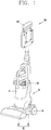
- a vacuum cleaner according to the present invention includes a cleaner body 10 to which a dust collecting container 12, in which dust and foreign substances existing on a surface to be cleaned, is mounted, a suction nozzle 30 disposed at a lower side of the cleaner body 10 such that the cleaner body 10 is mounted thereto, and configured to suck the dust and foreign substances scattered on the surface to be cleaned together with air, and a cleaner handle 100 provided on an upper side of the cleaner body 10 and gripped by the user to perform cleaning.
- the cleaner body 10 is rotatably coupled to an upper portion of the suction nozzle 30 such that an arrangement angle with respect to the surface to be cleaned can be varied, and the user may support the cleaner body 10 to maintain a state of the cleaner body 10 being rotated toward the surface to be cleaned.
- the dust collecting container 12 is detachably coupled to a front surface of the cleaner body 10.
- the dust collecting container 12 is provided with a dust separating member 50 for separating dust and foreign substances contained in air sucked into the cleaner body 10 by a cyclone principle.
- the air sucked into the cleaner body 10 through the suction nozzle 30 flows into the dust collecting container 12, and the dust and foreign substances contained in the air introduced into the dust collecting container 12 are filtered by the dust separating member 50 and collected in the dust collecting container 12.
- the clean air from which the dust and foreign substances have been separated is discharged to outside of the cleaner body 10.
- the user can detach the dust collecting container 12 from the cleaner body 10 to throw away the dust and foreign substances collected in the dust collecting container 12.
- the dust collecting container 12 illustrated in FIG. 1 has a cylindrical shape, but may alternatively be formed in a polygonal column shape such as a rectangular column, and the like.
- the suction nozzle 30 includes a nozzle unit 31 for sucking dust and foreign substances scattered on the surface to be cleaned together with air, and a mounting unit 32 on which the cleaner body 10 is mounted.
- the nozzle unit 31 moves back and forth and to right and left relative to the surface to be cleaned in order to suck dust, foreign substances, and the like present on the surface to be cleaned.
- a pair of wheels 33 is rotatably provided on both sides of the mounting unit 32 which is connected to the nozzle unit 31 and on which the cleaner body 10 is mounted.
- the mounting unit 32 connected to the nozzle unit 31 moves together.
- the wheels 33 smoothly rotate such that the suction nozzle 30 smoothly moves along the surface to be cleaned.
- a cleaner handle 100 is provided on the upper side of the cleaner body 10. Accordingly, the user can grasp (hold, grip) the cleaner handle 100 to support the cleaner body 10 such that the cleaner body 10 is maintained in a rotated state by a predetermined angle.
- the cleaner handle 100 is provided with an input unit (not shown) provided on a portion where the user actually grips the hand.
- the input unit may enable the user to input a signal while settling his or her hand on the cleaner handle 100.
- the input unit is positioned within a range where the user grips the cleaner handle 100. Accordingly, the user can input a signal without moving a gripped position with respect to the cleaner handle 100 while the user grips the cleaner handle 100. That is, the cleaner handle 100 is a member that allows the user to move the vacuum cleaner, whereas the input unit is a portion of the cleaner handle 100 with which the user's hand is actually brought into contact.
- the input unit may be provided with a plurality of grooves corresponding to fingers so that the fingers can be brought into contact with the grooves when user grips the cleaner handle. This may facilitate the user to input a signal to the input unit.
- the user may move the cleaner by inputting a signal to the input unit while settling the hand on the input unit.
- FIG. 2A a block diagram illustrating components of the vacuum cleaner illustrated in FIG. 1 is shown.
- the vacuum cleaner may include at least one of an input unit 60, an output unit 120, a power supply unit 130, a sensor unit 140, a driving unit 150, a dust removing unit 161, a dust storage unit 162, a cleaner handle 100, a controller 180, and an auxiliary driving unit 190.
- the input unit 60 receives various control commands for the cleaner from the user.
- the input unit 60 may include one or more buttons.
- the input unit 60 may include an adjustment button for adjusting an output of the cleaner, a power button for turning on and off the cleaner, a mode setting button for setting an operation mode of the cleaner, and the like.
- the input unit 60 may be installed on the cleaner handle 100 of the cleaner.
- the input unit 60 may be implemented as a hard key, a soft key, a touch pad, or the like.
- the input unit 60 may implement a form of a touch screen together with the output unit 120.
- the output unit 120 may be installed on the cleaner body 100 or the cleaner handle 100.
- an installation location and an installation type of the output unit 120 may vary.
- the output unit 120 may display information related to an output level, a battery status, an operation mode, and the like on the screen.
- the output unit 120 may be configured as one device of a light emitting diode (LED), a liquid crystal display (LCD), a plasma display panel, and an organic light emitting diode (OLED).
- LED light emitting diode
- LCD liquid crystal display
- OLED organic light emitting diode
- the output unit 120 may further include an audio output module for audibly outputting information related to an operation of the cleaner performed by the controller 180.
- the output unit 120 may output warning sound to the outside, in response to a warning signal generated by the controller 180.
- the audio output module may be means, such as a beeper, a speaker or the like for outputting sounds, and the output unit 120 may output sounds to the outside through the audio output module using audio data or message data, which has a predetermined pattern stored in a memory (not illustrated).
- the power supply unit 130 may apply a direct current (DC) voltage or an alternating current (AC) voltage to the vacuum cleaner.
- DC direct current
- AC alternating current
- the power supply unit 130 may include a first power supply module (not illustrated) that supplies AC power supplied from an external power supply device or a commercial power source directly into at least one component included in the cleaner.
- the first power supply module may include a rectifying circuit for converting AC power to DC power, a cord for transmitting the AC power from a commercial power source, and a cord reel for winding the cord therearound.
- the power supply unit 130 may include a second power supply module (not illustrated) that supplies DC power supplied from the battery to at least one component included in the cleaner. That is, the second power supply module may include a battery and a power terminal, and may supply power to the components of the vacuum cleaner using the DC power generated in the battery.
- the power supply unit 130 may store power supplied from an external power supply device in the battery, and supply the stored power to at least one component included in the cleaner.
- the battery may receive power from the external power supply device through the power supply unit by a wired/wireless charging scheme. That is, the battery may receive power by being directly connected to the external power supply device by a component such as a power consent through the power supply unit 130 included in the cleaner, or by being connected to the external power supply device using one of a magnetic resonance coupling method, an electromagnetic induction method, and a radiowave method.
- the vacuum cleaner can receive power from the battery provided therein when it is not connected to the external power source.
- the sensor unit 140 may include a pressure sensor part 141 and an encoder part 142.
- the pressure sensor part 141 may be disposed on an outer surface of the cleaner handle 100. That is, the pressure sensor part 141 may protrude to the outer surface of the cleaner handle 100. When the user holds the cleaner handle 100, the pressure sensor part 60 may be brought into contact with the user's hand.
- the pressure sensor part 141 may be disposed in the cleaner handle 100 so as to sense pressure that the user applies to a part of an outer surface of a grip unit 20.
- the sensor unit 140 may include at least one of an external signal sensor, a front sensor, a cliff sensor, a lower camera sensor, and an upper camera sensor.
- the external signal sensor may sense an external signal of a moving robot.
- the external signal sensor may be, for example, an infrared ray (IR) sensor, an ultrasonic sensor, a radio frequency (RF) sensor, or the like.
- IR infrared ray
- RF radio frequency
- the driving unit 150 provides suction force by a motor.
- the motor may be a Brushless DC (BLDC) motor used in a general cleaner, but is not limited thereto.
- BLDC Brushless DC
- the driving unit 150 may include a suction motor, and a suction fan rotated by the suction motor to generate the suction force.
- the driving unit 150 may include wheels for moving the cleaner body 10, and a driving motor for transmitting driving force to the wheels.
- the dust removing unit 161 and the dust storage unit 162 may be installed inside or outside the cleaner body 10 to facilitate coupling with and separation from the cleaner body 10.
- at least one of the dust removing unit 161 and the dust storage unit 162 may include a handle. The user may easily attach and detach at least one of the dust removing unit 161 and the dust storage unit 162 from the cleaner body 10 by holding the handle.
- the dust storage unit 162 includes a case. That is, the dust storage unit 162 may include a container for storing dust.
- the case communicates with the dust removing unit 161 to store therein dust separated in the dust removing unit 161. That is, the case forms a space or region which is separate from the dust removing unit 161, and stores dust therein.
- the controller 180 controls the overall operation of the components included in the cleaner.
- the controller 180 may provide or process appropriate information or functions to the user by processing signals, data, information, etc. input or output through the above-mentioned components or by activating application programs stored in a memory (not illustrated).
- controller 180 may control at least some of the components illustrated in FIG. 2A , to execute the application programs that have been stored in the memory. Further, the controller 180 may operate at least two of the components included in the cleaner in a combination manner for executing the application program.
- the controller 180 may determine whether the user has gripped the cleaner handle 100 based on a temperature value sensed by a temperature sensor (not illustrated) or a pressure value sensed by the pressure sensor part 141.
- the controller 180 may determine that the user has gripped the cleaner handle 100 when a temperature sensed by the temperature sensor disposed in the cleaner handle 100 is a reference temperature value or more.
- the reference temperature value may be set to substantially correspond to a body temperature.
- the controller 180 may set the reference temperature differently according to a current date or time.
- the controller 180 may store temperature values sensed by the temperature sensor at predetermined time intervals, and may set a reference temperature using the stored temperature values.
- the controller 180 may determine that the user has gripped the cleaner handle 100 when the temperature sensed by the temperature sensor is within a reference temperature range. For example, when the sensed temperature exceeds an upper limit of the reference temperature range, the controller 180 may determine that heat applied to the temperature sensor is due to an object other than the user, and stop the operation of the driving unit 150.
- the controller 180 may also determine that the user has gripped the cleaner handle 100 when pressure sensed by the pressure sensor part 141 included in the cleaner handle 100 is a reference pressure value or more.
- the reference pressure value may be set by the user.
- the output unit 120 may output guide information to the user to set the reference pressure value when the cleaner is initially operated, and the controller 180 may set the reference pressure value based on pressure applied to the pressure sensor part 141 after the guide information is output.
- the output unit 120 may output voice information "Please grip the handle" when the cleaner is initially driven or when the cleaner operates in a mode for resetting the reference pressure value.
- the controller 180 may set the reference pressure value by processing information related to the pressure applied to the pressure sensor part 141 at a plurality of time points during a preset time interval after the voice information is output.
- the guide information is not limited to the voice information and may alternatively be output in various forms.
- the controller 180 may determine that the user has gripped the cleaner handle 100 when the sensed pressure is within the reference pressure range. On the other hand, when the sensed pressure exceeds the upper limit of the reference pressure range, the controller 180 may determine that the pressure applied to the pressure sensor part 141 is due to an object other than the user, and stop the operation of the driving unit 150.
- the controller 180 may operate the driving unit 150 when it is determined that the user has gripped the cleaner handle 100, and stop the driving unit 150 when it is determined that the user has not gripped the cleaner handle 100.
- the controller 180 may control the driving unit 150 to generate suction force of the cleaner when it is determined using at least one of the temperature sensor and the pressure sensor part 141 provided in the cleaner handle 100 that the user has gripped the cleaner handle 100.
- the controller 180 may control the driving unit 150 to adjust strength (intensity, magnitude) of the suction force generated in the driving unit 150 according to strength of the sensed pressure. That is, the controller 180 may control the driving unit 150 to increase an output of the cleaner as the user grips the cleaner handle 100 stronger.
- the controller 180 may be provided inside the cleaner body 10 of the cleaner or inside the cleaner handle 100.
- the input unit 60, the output unit 120, the sensor unit 140 and the controller 180 of the cleaner may be provided inside or outside the cleaner handle 100.
- the input unit 60, the output unit 120, the power supply unit 130, the sensor unit 140, the driving unit 150, and the controller 180 of the cleaner according to another embodiment of the present invention may be provided in the cleaner body of the cleaner.
- the input unit 60, the output unit 120, the sensor unit 140, and the controller 180 of the cleaner may be provided in the cleaner handle 100 and the cleaner body, respectively.
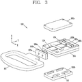
- a positive direction of a Y-axis illustrated in FIG. 3 is defined as a forward direction of the cleaner.
- a negative direction of the Y-axis illustrated in FIG. 3 is defined as a backward direction of the cleaner.
- a positive direction of a Z-axis illustrated in FIG. 3 is defined as an upward direction.
- a negative direction of the Z-axis illustrated in FIG. 3 is defined as a downward direction.
- a positive direction of an X-axis illustrated in FIG. 3 is defined as a left direction.
- a negative direction of the X-axis illustrated in FIG. 3 is defined as a right direction.
- the cleaner handle 100 may include a grip member 101, a guide module 102, a handle body 104, and a pressure sensor 105.
- the grip member 101 may be formed to be movable in the forward direction or the backward direction of the cleaner, and gripped by the user.
- the guide module 102 may be coupled with the grip member 101 to guide the grip member 101 to move in the forward direction or the backward direction of the cleaner.
- the handle body 104 may allow the guide module 102 to be movable in the forward direction or the backward direction of the cleaner.
- a portion of the guide module 102 may be formed to be inserted through a hole formed in the handle body 104. Further, a portion of the guide module 102 may be formed to be in contact with different surfaces of the handle body 104.
- the guide module 102 may be slidably moved relative to the handle body 104 by external force applied by the user.
- the guide module 102 may move in the forward or backward direction of the cleaner in a state of being in contact with the handle body 104.
- a pressure sensor 105 may sense pressure generated between the guide module 102 and the handle body 104, in response to the grip member 101 moving in the forward or backward direction of the cleaner.
- the handle body 104 may be provided with grooves 114 on a surface, on which the guide module 102 is provided, of outer surfaces of the handle body 104, to guide the movement of the guide module 102.
- each of the grooves 114 may be formed to have a width of a predetermined length so as to be parallel with the forward direction or the backward direction of the cleaner.
- the guide module 102 may include a first plate 102a and a second plate 102b. That is, the guide module 102 may be formed of an assembly of the first plate 102a and the second plate 102b.
- the guide module 102 may include a first coupling member 103a and a second coupling member 103b for coupling the first and second plates 102a and 102b.
- the first coupling member 103a may be located between the handle body 104 and the grip member 101.
- the second coupling member 103b may be located in a hole 124 formed in the handle body 104.
- One end of the first plate 102a at the side of the grip member 101 and one end of the second plate 102b at the side of the grip member 101 may be coupled to both ends of the first coupling member 103a, respectively.
- One end of the first plate 102a at the side of the cleaner body and one end of the second plate 102b at the side of the cleaner body may be coupled to both ends of the second coupling member 103b, respectively.
- the guide module 102 may be formed of an assembly of the first plate 102a, the second plate 102b, the first coupling member 103a, and a second coupling member 103b.
- the handle body 104 may be located between the first plate 102a and the second plate 102b.
- a part of the assembly forming the guide module 102 may be inserted through the hole 124 formed in the handle body 104.
- At least one of the first and second plates 102a and 102b may be provided with ribs 112.
- the ribs 112 protruding toward the handle body 104 may be provided on surfaces of the first and second plates 102a and 102b, which face the handle body 104, respectively.
- the ribs 112 provided on at least one of the first and second plates 102a and 120b may be inserted into the grooves 114 formed in the handle body 104.
- a shape of the groove 114 may be formed to substantially correspond to a shape of the rib 112.
- a width of the groove 114 may be greater than a width of the rib 112.
- the rib 112 may be made of an elastic material.
- Materials making the ribs 112 and the grooves 114 may be selected so that frictional force generated between an outer surface of the rib 112 and an outer surface of the groove 114 has a predetermined strength or less.
- the shapes of the grooves 114 and the ribs 112 are not limited to the embodiment illustrated in FIG. 3 and may alternatively be formed in various shapes to maintain the coupled state between the guide module 102 and the handle body 104 without interfering with the movement of the guide module 102.
- the pressure sensor part 141 may include a first pressure sensor unit 105a and a second pressure sensor unit 105b.
- the first pressure sensor unit 105a may sense information related to strength of pressure applied by the guide module 102 to a part of the handle body 104.
- the second pressure sensor unit 105b may sense information related to strength of pressure applied by the guide module 102 to a part of the handle body 104.
- the first pressure sensor unit 105a may be provided on one surface of the first coupling member 103a of the guide module 102.
- the one surface of the first coupling member 103a provided with the first pressure sensor unit 105a may be a surface, which faces the handle body 104, of outer surfaces of the first coupling member 103a.
- the first pressure sensor unit 105a may also be provided on one surface of the first coupling member 103a of the guide module 102.
- the one surface of the first coupling member 103a provided with the first pressure sensor unit 105a may face the handle body 104.
- the one surface of the first coupling member 103a provided with the first pressure sensor unit 105a may be a surface, which faces another surface of the first coupling member 103a provided with the grip member 101, of the outer surfaces of the first coupling member 103a. That is, the grip member 101 may be coupled to the another surface of the first coupling member 103a, which is opposite to the one surface provided with the first pressure sensor unit 105a.
- a buffer member 106 (i., 106a) may be provided between the first pressure sensor unit 105a and the first coupling member 103a.
- a buffer member 106 (i., 106b) may be provided between the second pressure sensor unit 105b and the second coupling member 103b.
- the buffer member 106 may prevent breakdown of the pressure sensor part 141 by reducing an impact applied by the guide module 102 to the pressure sensor part 141.
- a distance between a point where the first pressure sensor unit 105a is installed and a point where the second pressure sensor unit 105b is installed may be shorter than a length of the handle body 104 in the forward direction or the backward direction of the cleaner.
- a polygon which is formed by an inner circumferential surface of the guide module 102 may have a length in the forward or backward direction of the cleaner, which is shorter than a length of the handle body 104 in the forward or backward direction of the cleaner, so that the guide module 102 can be slid relative to the handle body 104.
- a distance between one surface of the first coupling member 103a and one surface of the second coupling member 103b may be shorter than the length of the handle body 104 in the forward or backward direction of the cleaner, so that the guide module 102 can be slid relative to the handle body 104.
- the one surface of the first coupling member 103a and the one surface of the second coupling member 103b may face each other.
- a distance between the first coupling member and the second coupling member or a distance between the first pressure sensor unit and the second pressure sensor unit can be shorter than the length of the handle body 104 in the forward or backward direction of the cleaner, and accordingly the first pressure sensor unit and the second pressure sensor unit provided on the first coupling member and the second coupling member, respectively, can be brought into contact with the handle body in a direction of external force applied by the user.
- the distance between the point where the first pressure sensor unit 105a is installed and the point where the second pressure sensor unit 105b is installed may be longer than a distance from an inner circumferential surface of the hole 124 formed in the handle body 104 to an outer surface of the handle body 105 at the side of the grip member 101.
- the distance between the one surface of the first coupling member 103a and the one surface of the second coupling member 103b may be longer than the distance from the inner circumferential surface of the hole 124 formed in the handle body 104 to the outer surface of the handle body 104 at the side of the grip member 101.
- the one surface of the first coupling member 103a and the one surface of the second coupling member 103b may face each other.
- the distance between the first coupling member and the second coupling member or the distance between the first pressure sensor unit and the second pressure sensor unit can be longer than the distance from the inner circumferential surface of the hole 124 formed in the handle body 104 to the outer surface of the handle body 104 at the side of the grip member 101, and thus the guide module 102 can be coupled to the grip member 101 while being inserted through the hole 124 of the handle body 104.
- the cleaner handle according to the present invention may include a control module (not illustrated) which is separate from the controller 180 of the cleaner, and the control module may determine using a sensed value received from the pressure sensor part 141 whether the user is moving the cleaner forward or backward.
- a control module (not illustrated) which is separate from the controller 180 of the cleaner, and the control module may determine using a sensed value received from the pressure sensor part 141 whether the user is moving the cleaner forward or backward.
- the pressure sensor part 141 of the cleaner handle according to the present invention may be connected to the controller 180 of the cleaner.
- the controller 180 may use the sensed value received from the pressure sensor part 141 to determine whether the user is moving the cleaner forward or backward.
- the controller 180 may compare an output of the first pressure sensor unit 105a with an output of the second pressure sensor unit 105b to determine whether the user is moving the cleaner forward or backward.
- the controller 180 may also compare the output of the first pressure sensor unit 105a with the output of the second pressure sensor unit 105b to determine whether the cleaner body is moving forward or backward.
- the controller 180 may determine that the user applies external force to the grip member 101 to move the cleaner forward when the output of the first pressure sensor unit 105a is larger than the output of the second pressure sensor unit 105b.
- the controller 180 may determine that the user applies external force to the grip member 101 to move the cleaner forward when the output of the first pressure sensor unit 105a exceeds a reference output value.
- the controller 180 may determine that the user applies external force to the grip member 101 to move the cleaner forward when an increase rate of the output of the first pressure sensor unit 105a exceeds a reference increase rate value.
- the controller 180 may determine that the user applies external force to the grip member 101 to move the cleaner forward when it is determined that a rate of change of the output of the first pressure sensor unit 105a is increasing while monitoring the output of the first pressure sensor unit 105a.
- controller 180 may control the driving unit 150 to provide auxiliary driving force in the determined direction.
- the controller 180 may control the driving unit 150 to provide auxiliary driving force in the forward direction.
- the controller 180 may control the driving unit 150 to provide auxiliary driving force in the backward direction.
- the controller 180 may control the driving unit 150 to generate driving force in the determined advancing direction or increase the existing driving force so as to assist the travel of the cleaner.
- the grip member 101 and one end of the guide module 102 may be coupled by a predetermined number of fixing members 107.
- the fixing members 107 may be bolts.
- coupled portions between the grip member 101 and the guide module 102 may be provided with accommodating portions for accommodating the fixing members 107, respectively.
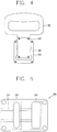
- FIG. 5 is a front view of the handle body 104.
- the handle body 104 may be provided with a hole 124 through which a portion of the guide module 102 is inserted.
- the handle body 104 may be provided with a separate opening 134 that does not allow the guide module 102 to be inserted therethrough. This may result in reducing a weight of the handle body 104.
- a size of the opening 134 may be smaller than or equal to a predetermined ratio value of an area of a surface, which faces an upper side, of the outer surfaces of the handle body 104.
- a volume corresponding to the opening 134 may be less than a predetermined ratio value of a volume of the handle body 104.
- the handle body 104 may have a plurality of holes in addition to the hole 124 and the opening 134, and the guide module 102 may be placed on the handle body 104 while a part thereof is inserted through one of the hole 124, the opening 134 and the plurality of holes. That is, the guide module 102 may be slid relative to the handle body 104 in a state where the part of the guide module 102 is inserted through one of the hole 124, the opening 134 and the plurality of holes of the handle body 104.
- the guide module 102 formed in various sizes can be settled on the handle body 104.
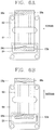
- FIGS. 6A and 6B one method of operating the cleaner handle according to one embodiment of the present invention will be described with reference to FIGS. 6A and 6B .
- FIGS. 6A and 6B illustrate an example of an operation of the cleaner handle when the user applies external force to the cleaner handle illustrated in FIG. 3 in the forward or backward direction of the cleaner.
- the first pressure sensor unit 105a provided on the first coupling member 103a may be brought into contact with the handle body 104.
- the guide module 102 may move in the forward direction of the cleaner with respect to the handle body 104 by the external force applied by the user to the grip member 101. Particularly, the guide module 102 may be slid in the forward direction of the cleaner until at least one of the first pressure sensor unit 105a and the first coupling member 103a are brought into contact with the handle body 104.
- the first pressure sensor unit 105a may detect information related to strength of pressure applied from the outer surface of the handle body 104.
- the first pressure sensor unit 105a may detect whether or not pressure is applied simply from the handle body 104.
- the first pressure sensor unit 105a may detect information related to the strength of the pressure applied from the handle body 104 at predetermined intervals.
- the guide module 102 may not move any more.
- the second pressure sensor unit 105b and the second coupling member 103b may be spaced apart from the inner circumferential surface of the hole 124.
- the guide module 102 may be formed such that the second pressure sensor unit 105b and the second coupling member 103a are spaced apart from the inner circumferential surface of the hole 124 when the first pressure sensor unit 105a is in contact with the part of the outer surface of the handle body 104.
- the second coupling member 103b may come into contact with the inner circumferential surface of the hole 124 even before the first pressure sensor unit 105a comes in contact with the handle body 104 yet.
- the guide module 102 when the guide module 102 is formed excessively short, the guide module 102 may fail to be connected to the grip member 101 in the state where the part of the guide module 102 is inserted through the hole 124 of the handle body 104, as illustrated in FIG. 4 .
- the length of the guide module 102 may be decided such that the guide module 102 can move relative to the handle body 104 along the direction of force applied by the user to the grip member 101 in the state where the part of the guide module 102 is inserted through the hole 124.
- the second pressure sensor unit 105b provided on the second coupling member 103b may come in contact with the handle body 104.
- the guide module 102 may move relative to the handle body 104 in the backward direction of the cleaner, by external force applied by the user to the grip member 101. Particularly, the guide module 102 may be slid in the backward direction of the cleaner until at least one of the second pressure sensor unit 105b and the second coupling member 103b comes in contact with the inner circumferential surface of the hole 124 formed in the handle body 104.
- the second pressure sensor unit 105b may detect information related to strength of pressure applied from the inner circumferential surface of the hole 124.
- the second pressure sensor unit 105b may detect whether or not pressure is applied simply from the inner circumferential surface of the hole 124.
- the second pressure sensor unit 105b may detect information related to the strength of the pressure applied from the inner circumferential surface of the hole 124 at predetermined intervals.
- the guide module 102 may not move any more.
- first pressure sensor unit 105a and the first coupling member 103a may be spaced apart from the outer surface of the handle body 104 in the state where the second pressure sensor unit 105b comes in contact with the part of the inner circumferential surface of the hole 124.
- the first pressure sensor unit 105a and the second pressure sensor unit 105b may be installed at the inner circumferential surface of the hole 124.
- first pressure sensor unit 105a and the second pressure sensor unit 105b may be provided at the inner circumferential surface of the hole 124 in a manner of facing each other.
- the first pressure sensor unit 105a may be disposed on one surface of the inner circumferential surface of the hole 124, which faces the grip member 101, and the second pressure sensor unit 105b may be disposed on a surface of the inner circumferential surface of the hole, which faces the one surface.
- the first pressure sensor unit 105a may be disposed on a part of the inner circumferential surface of the hole 124 existing in the forward direction of the cleaner based on the second coupling member 103b located inside the hole 124, and the second pressure sensor unit 105b may be disposed on another part of the inner circumferential surface of the hole 124 existing in the backward direction of the cleaner based on the second coupling member 103b.
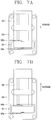
- FIGS. 7A and 7B have not illustrated a buffer member separately, but the buffer members may alternatively be provided between the first pressure sensor unit 105a and the second pressure sensor unit 105b and the inner circumferential surface of the hole 124, depending on the user's selection.
- FIGS. 7A and 7B have not illustrated the first and second coupling members separately, but the feature that the first and second coupling members are provided on both ends of the guide module 102 has been described with reference to FIGS. 3 , 6A and 6B .
- the first pressure sensor unit 105a may be brought into contact with the guide module 102.
- the guide module 102 may move relative to the handle body 104 in the forward direction of the cleaner by external force applied by the user to the grip member 101.
- the guide module 102 may be slid in the forward direction of the cleaner until the first pressure sensor unit 105a comes in contact with the second coupling member 103b.
- the first pressure sensor unit 105a may detect information related to strength of pressure applied from an outer surface of the guide module 102.
- the first pressure sensor unit 105a may detect information related to strength of pressure applied from an outer surface of the second coupling member 103b in the forward direction of the cleaner.
- the first pressure sensor unit 105a may detect whether or not pressure is applied simply from the guide module 102.
- the first pressure sensor unit 105a may detect information related to the strength of the pressure applied from the guide module 102 at predetermined intervals.
- the second pressure sensor unit 105b may be spaced apart from the guide module 102.
- the second pressure sensor unit 105b provided on the inner circumferential surface of the hole 124 may be brought into contact with the guide module 102.
- the guide module 102 may move relative to the handle body 104 in the backward direction of the cleaner, by external force applied by the user to the grip member 101.
- the guide module 102 may be slid in the backward direction of the cleaner until the second pressure sensor unit 105b comes in contact with the second coupling member 103b.
- the second pressure sensor unit 105b may detect information related to strength of pressure applied from the guide module 102.
- the second pressure sensor unit 105b may detect information related to strength of pressure applied from the outer surface of the second coupling member 103b in the backward direction of the cleaner.
- the second pressure sensor unit 105b may detect whether or not pressure is applied simply from the guide module 102.
- the second pressure sensor unit 105b may detect information related to the strength of the pressure applied from the guide module 102 at predetermined intervals.
- the first pressure sensor unit 105a may be spaced apart from the guide module 102.
- the guide module 12 is formed by two plates 102a, 102b; multiple grooves and ribs are formed between the two plates 102a, 102b and the handle body 104; and the guide module 102 comprises two coupling members 103a, 103b.
- the guide module 12 may be formed by single plate which is structurally engaged with the handle body 104 so as for the single plate not to be detached from the handle body 104.
- the multiple sets of grooves and ribs formed in the two plates 102a, 102b and the handle body 104 may be simplified by one single set of groove and rib.
- the single rib may be formed in either one of the plates 102a, 102b.
- at least a portion of the two coupling members 103a, 103b may be integrally formed with the guide module 102 so as for one of the two coupling members 103a, 103b to be removed due to such integrated structure.
- a vacuum cleaner and a control method thereof According to a vacuum cleaner and a control method thereof according to the present invention, user's intention to move the cleaner can be recognized and thus auxiliary driving force can be provided in a direction intended by the user, thereby improving user's convenience.
- the user of the vacuum cleaner according to the present invention can easily move a cleaner body in a desired direction even with small force.
- a load applied on the user's finger or wrist can be minimized, thereby improving the user's convenience.
Abstract
Description
- The present invention relates to a vacuum cleaner capable of moving a cleaner body by assisting a user, a handle of the vacuum cleaner, and a method of controlling the cleaner, and more particularly, a vacuum cleaner capable of moving a cleaner body by facilitating a user's operation.
- Generally, a vacuum cleaner is an apparatus that sucks dust, foreign substances and the like existing on a surface to be cleaned by using a suction motor provided inside a main body, and then filters the dust and foreign substances within the main body.
- In recent years, a battery is mounted in the vacuum cleaner to supply power to the cleaner, such that a cleaning function can be executed even in a state where the cleaner is not connected to an external power source through a power line. In addition, the vacuum cleaner may include a driving unit that generates driving force by receiving power from the battery, and a controller of the vacuum cleaner may perform autonomous travel by controlling the driving unit according to a preset algorithm.
- The vacuum cleaner may be classified into an upright type vacuum cleaner in which a suction nozzle is connected to a main body and moves together with a main body, and a canister type vacuum cleaner in which a suction nozzle is connected to a main body through an extension pipe, a handle, a hose, or the like.
- Of the two types of vacuum cleaners, the upright type vacuum cleaner includes a cleaner main body in which a suction motor for generating suction force and the like are disposed, a suction nozzle for sucking dust, foreign substances and the like, which are present on a surface to be cleaned, into the main body by the suction force generated in the suction motor, a handle provided on a top of the main body to be gripped by a user such that the suction nozzle moves along the surface to be cleaned, and the like.
- That is, when power is applied to the main body and the suction motor is driven, suction force is generated, and air containing dust and foreign substances scattered on the surface to be cleaned is sucked into the suction nozzle by the suction force.
- The air containing the dust, the foreign substances, and the like flows into the main body, and the dust, the foreign substances, and the like are separated from the air into a dust collecting container mounted in the main body by a cyclone principle.
- The separated dust, foreign substances, and the like are collected in the dust collecting container, and the separated air is discharged to outside of the main body through an air discharge port.
- Since such vacuum cleaner is moved only by the user's force, the user's fatigue is caused when friction against the surface to be cleaned or a load of the cleaner is great while the user cleans the surface with moving the cleaner.
- In particular, the upright type vacuum cleaner has a relatively heavy weight as compared with other types of vacuum cleaners, which causes user's inconvenience in using the upright type vacuum cleaner.
- In order to solve such problems, the typical upright type vacuum cleaner may be provided with wheels which are rotated in response to physical force applied by the user.
- However, there is a problem that it is difficult to smoothly move the vacuum cleaner in a user-desired direction merely by employing the wheels which are passively rotated.
- That is, in case of a vacuum cleaner having only passively-rotating wheels, when the user applies physical force to the vacuum cleaner in a specific direction, the wheels are rotated merely in response to the applied physical force, and any separate driving force for supplementing the user's physical force is not applied. Accordingly, when the user moves the upright type cleaner having only the passively-rotating wheels, the user cannot easily move the heavy main body of the cleaner.
- An aspect of the present invention is to provide a vacuum cleaner, which performs a travel algorithm that reflects user's intention, to facilitate movement or travel of an upright type vacuum cleaner according to the user's intention, and a handle of the cleaner.
- Another aspect of the present invention is to provide a vacuum cleaner, which actively reflects user's intention by providing separate physical force that assists movement of the cleaner in a user-intended direction, and a handle of the cleaner.
- Another aspect of the present invention is to provide an upright type vacuum cleaner that follows a user, and a handle of the cleaner.
- To achieve these and other advantages and in accordance with the purpose of the present invention, as embodied and broadly described herein, there is provided a handle for a cleaner, the handle including a grip member formed to be movable in a forward direction or a backward direction of the cleaner and gripped by a user, a guide module to guide the grip member to move in the forward direction or the backward direction of the cleaner, a handle body provided to move the guide module in the forward or backward direction of the cleaner, and a pressure sensor part to detect pressure generated between the guide module and the handle body, in response to the grip member moving in the forward direction or the backward direction of the cleaner.
- According to one embodiment of the present invention, the handle body may be provided with grooves formed on a surface, on which the guide module is disposed, of outer surfaces of the handle body, to guide the movement of the guide module.
- According to one embodiment of the present invention, the guide module may include a first plate and a second plate, and the handle body may be located between the first plate and the second plate.
- According to one embodiment of the present invention, ribs may be provided respectively on surfaces of the first and second plates, which face the handle body, and the ribs may be inserted into the grooves provided in the outer surface of the handle body.
- According to one embodiment of the present invention, each of the grooves may be formed to have a width of a predetermined length so as to be parallel with the forward or backward direction.
- According to one embodiment of the present invention, a width of each of the ribs provided on the first and second plates may be smaller than the width of the groove.
- According to one embodiment of the present invention, the guide module may include a first coupling member and a second coupling member to couple the first and second plates to each other. The first coupling member may be located between the handle body and the grip member, and the second coupling member may be located in a hole formed in the handle body.
- According to one embodiment of the present invention, the pressure sensor part may include a first pressure sensor unit and a second pressure sensor unit. The first pressure sensor unit may detect information related to strength of pressure applied by the guide module when a user moves the grip member in the forward direction to be brought into contact with the guide module, and the second pressure sensor unit may detect information related to strength of pressure applied by the guide module when the user moves the grip member in the backward direction to be brought into contact with the guide module.
- According to one embodiment of the present invention, the first pressure sensor unit may be provided on one surface of the first coupling member.
- According to one embodiment of the present invention, a buffer member may be provided between the first pressure sensor unit and the first coupling member.
- According to one embodiment of the present invention, the second pressure sensor unit may be provided on one surface of the second coupling member.
- According to one embodiment of the present invention, the grip member may be coupled to another surface of the first coupling member, which is opposed to the one surface having the first pressure sensor unit.
- According to one embodiment of the present invention, a distance between a point where the first pressure sensor unit is installed and a point where the second pressure sensor unit is installed may be shorter than a length of the handle body in the forward or backward direction.
- According to another aspect of the present invention, there is provided a cleaner, including a cleaner body, a handle provided on the cleaner body and gripped by a user, a driving unit provided at a lower portion of the cleaner body to move the cleaner body, and a controller to control the driving unit based on detected pressure. The handle may include a grip member formed to be movable in a forward direction or a backward direction of the cleaner body, a guide module to guide the grip member to move in the forward direction or the backward direction of the cleaner, a handle body coupled with the guide module, and a pressure sensor part to detect pressure generated between the guide module and the handle body, in response to the grip member moving in the forward direction or the backward direction of the cleaner. The controller may determine whether the cleaner body moves forward or backward using information detected by a pressure sensor part, and control the driving unit based on the determination result.
- According to one embodiment of the present invention, the pressure sensor part may include a first pressure sensor unit and a second pressure sensor unit. The first pressure sensor unit may detect information related to strength of pressure applied by the guide module when the user moves the grip member in the forward direction to be brought into contact with the guide module, and the second pressure sensor unit may detect information related to strength of pressure applied by the guide module when the user moves the grip member in the backward direction to be brought into contact with the guide module.
- According to one embodiment of the present invention, the controller may determine that the cleaner body is moving forward when an output of the first pressure sensor unit is greater than or equal to a predetermined value, and control the driving unit to provide auxiliary driving force in the forward direction of the cleaner body.
- According to one embodiment of the present invention, the controller may determine that the cleaner body is moving backward when an output of the second pressure sensor unit is greater than or equal to a predetermined value, and control the driving unit to provide auxiliary driving force in the backward direction of the cleaner body.
- According to a vacuum cleaner and a control method thereof according to the present invention, user's intention to move the cleaner can be recognized so that auxiliary driving force can be provided in a direction intended by the user, thereby improving user's convenience.
- Further, the user of the vacuum cleaner according to the present invention can easily move a cleaner body in a desired direction even with small force. In addition, according to these advantages, a load applied on the user's finger or wrist can be minimized, thereby improving the user's convenience.
-
-
FIG. 1 is a conceptual view illustrating a vacuum cleaner to which the present invention is applicable. -
FIGS. 2A and 2B are block diagrams of a cleaner according to the present invention. -
FIG. 3 is a conceptual view illustrating detailed components of a cleaner handle according to the present invention. -
FIG. 4 is a front view of a cleaner handle according to the present invention. -
FIG. 5 is a front view of a handle body included in the cleaner handle according to the present invention. -
FIGS. 6A and 6B are conceptual views illustrating a method of operating a cleaner handle according to one embodiment of the present invention. -
FIGS. 7A and 7B are conceptual views illustrating a method of operating a cleaner handle according to another embodiment of the present invention. - Hereinafter, description will be given in detail of embodiments disclosed herein. Technical terms used in this specification are merely used for explaining specific embodiments, and should not be constructed to limit the scope of the technology disclosed herein.
- Referring to
FIG. 1 , a vacuum cleaner according to the present invention includes acleaner body 10 to which adust collecting container 12, in which dust and foreign substances existing on a surface to be cleaned, is mounted, asuction nozzle 30 disposed at a lower side of thecleaner body 10 such that thecleaner body 10 is mounted thereto, and configured to suck the dust and foreign substances scattered on the surface to be cleaned together with air, and acleaner handle 100 provided on an upper side of thecleaner body 10 and gripped by the user to perform cleaning. - The
cleaner body 10 is rotatably coupled to an upper portion of thesuction nozzle 30 such that an arrangement angle with respect to the surface to be cleaned can be varied, and the user may support thecleaner body 10 to maintain a state of thecleaner body 10 being rotated toward the surface to be cleaned. - The
dust collecting container 12 is detachably coupled to a front surface of thecleaner body 10. Thedust collecting container 12 is provided with adust separating member 50 for separating dust and foreign substances contained in air sucked into thecleaner body 10 by a cyclone principle. - That is, the air sucked into the
cleaner body 10 through thesuction nozzle 30 flows into thedust collecting container 12, and the dust and foreign substances contained in the air introduced into thedust collecting container 12 are filtered by thedust separating member 50 and collected in thedust collecting container 12. The clean air from which the dust and foreign substances have been separated is discharged to outside of thecleaner body 10. - Since the
dust collecting container 12 is detachably coupled to thecleaner body 10, the user can detach thedust collecting container 12 from thecleaner body 10 to throw away the dust and foreign substances collected in thedust collecting container 12. - Meanwhile, the
dust collecting container 12 illustrated inFIG. 1 has a cylindrical shape, but may alternatively be formed in a polygonal column shape such as a rectangular column, and the like. - The
suction nozzle 30 includes anozzle unit 31 for sucking dust and foreign substances scattered on the surface to be cleaned together with air, and a mountingunit 32 on which thecleaner body 10 is mounted. - When the user carries out cleaning, the
nozzle unit 31 moves back and forth and to right and left relative to the surface to be cleaned in order to suck dust, foreign substances, and the like present on the surface to be cleaned. - A pair of
wheels 33 is rotatably provided on both sides of the mountingunit 32 which is connected to thenozzle unit 31 and on which thecleaner body 10 is mounted. - That is, when the
nozzle unit 31 moves relative to the surface to be cleaned, the mountingunit 32 connected to thenozzle unit 31 moves together. Thewheels 33 smoothly rotate such that thesuction nozzle 30 smoothly moves along the surface to be cleaned. - On the other hand, a
cleaner handle 100 is provided on the upper side of thecleaner body 10. Accordingly, the user can grasp (hold, grip) thecleaner handle 100 to support thecleaner body 10 such that thecleaner body 10 is maintained in a rotated state by a predetermined angle. - The
cleaner handle 100 is provided with an input unit (not shown) provided on a portion where the user actually grips the hand. The input unit may enable the user to input a signal while settling his or her hand on thecleaner handle 100. - The input unit is positioned within a range where the user grips the
cleaner handle 100. Accordingly, the user can input a signal without moving a gripped position with respect to thecleaner handle 100 while the user grips thecleaner handle 100. That is, thecleaner handle 100 is a member that allows the user to move the vacuum cleaner, whereas the input unit is a portion of thecleaner handle 100 with which the user's hand is actually brought into contact. - Therefore, the input unit may be provided with a plurality of grooves corresponding to fingers so that the fingers can be brought into contact with the grooves when user grips the cleaner handle. This may facilitate the user to input a signal to the input unit.
- The user may move the cleaner by inputting a signal to the input unit while settling the hand on the input unit.
- Referring to
FIG. 2A , a block diagram illustrating components of the vacuum cleaner illustrated inFIG. 1 is shown. - The vacuum cleaner may include at least one of an
input unit 60, anoutput unit 120, apower supply unit 130, asensor unit 140, adriving unit 150, adust removing unit 161, adust storage unit 162, acleaner handle 100, acontroller 180, and anauxiliary driving unit 190. - The
input unit 60 receives various control commands for the cleaner from the user. Theinput unit 60 may include one or more buttons. For example, theinput unit 60 may include an adjustment button for adjusting an output of the cleaner, a power button for turning on and off the cleaner, a mode setting button for setting an operation mode of the cleaner, and the like. - Further, the
input unit 60 may be installed on thecleaner handle 100 of the cleaner. In addition, theinput unit 60 may be implemented as a hard key, a soft key, a touch pad, or the like. For example, theinput unit 60 may implement a form of a touch screen together with theoutput unit 120. - Meanwhile, the
output unit 120 may be installed on thecleaner body 100 or thecleaner handle 100. Of course, an installation location and an installation type of theoutput unit 120 may vary. For example, theoutput unit 120 may display information related to an output level, a battery status, an operation mode, and the like on the screen. - The
output unit 120 may be configured as one device of a light emitting diode (LED), a liquid crystal display (LCD), a plasma display panel, and an organic light emitting diode (OLED). - The
output unit 120 may further include an audio output module for audibly outputting information related to an operation of the cleaner performed by thecontroller 180. For example, theoutput unit 120 may output warning sound to the outside, in response to a warning signal generated by thecontroller 180. - In this case, the audio output module may be means, such as a beeper, a speaker or the like for outputting sounds, and the
output unit 120 may output sounds to the outside through the audio output module using audio data or message data, which has a predetermined pattern stored in a memory (not illustrated). - The
power supply unit 130 may apply a direct current (DC) voltage or an alternating current (AC) voltage to the vacuum cleaner. - That is, the
power supply unit 130 may include a first power supply module (not illustrated) that supplies AC power supplied from an external power supply device or a commercial power source directly into at least one component included in the cleaner. The first power supply module may include a rectifying circuit for converting AC power to DC power, a cord for transmitting the AC power from a commercial power source, and a cord reel for winding the cord therearound. - In addition, the
power supply unit 130 may include a second power supply module (not illustrated) that supplies DC power supplied from the battery to at least one component included in the cleaner. That is, the second power supply module may include a battery and a power terminal, and may supply power to the components of the vacuum cleaner using the DC power generated in the battery. - Meanwhile, the
power supply unit 130 may store power supplied from an external power supply device in the battery, and supply the stored power to at least one component included in the cleaner. At this time, the battery may receive power from the external power supply device through the power supply unit by a wired/wireless charging scheme. That is, the battery may receive power by being directly connected to the external power supply device by a component such as a power consent through thepower supply unit 130 included in the cleaner, or by being connected to the external power supply device using one of a magnetic resonance coupling method, an electromagnetic induction method, and a radiowave method. - The vacuum cleaner can receive power from the battery provided therein when it is not connected to the external power source.
- Referring to
FIG. 2B , thesensor unit 140 may include apressure sensor part 141 and anencoder part 142. - The
pressure sensor part 141 may be disposed on an outer surface of thecleaner handle 100. That is, thepressure sensor part 141 may protrude to the outer surface of thecleaner handle 100. When the user holds thecleaner handle 100, thepressure sensor part 60 may be brought into contact with the user's hand. - That is, the
pressure sensor part 141 may be disposed in thecleaner handle 100 so as to sense pressure that the user applies to a part of an outer surface of agrip unit 20. - Although not illustrated in
FIG. 2B , thesensor unit 140 may include at least one of an external signal sensor, a front sensor, a cliff sensor, a lower camera sensor, and an upper camera sensor. - The external signal sensor may sense an external signal of a moving robot. The external signal sensor may be, for example, an infrared ray (IR) sensor, an ultrasonic sensor, a radio frequency (RF) sensor, or the like.
- The driving
unit 150 provides suction force by a motor. Here, the motor may be a Brushless DC (BLDC) motor used in a general cleaner, but is not limited thereto. - The driving
unit 150 may include a suction motor, and a suction fan rotated by the suction motor to generate the suction force. - The driving
unit 150 may include wheels for moving thecleaner body 10, and a driving motor for transmitting driving force to the wheels. - Hereinafter, a more detailed embodiment of the
driving unit 150 according to the present invention will be described with reference toFIGS. 5A to 5C . - The
dust removing unit 161 and thedust storage unit 162 may be installed inside or outside thecleaner body 10 to facilitate coupling with and separation from thecleaner body 10. For example, at least one of thedust removing unit 161 and thedust storage unit 162 may include a handle. The user may easily attach and detach at least one of thedust removing unit 161 and thedust storage unit 162 from thecleaner body 10 by holding the handle. - Meanwhile, the
dust storage unit 162 includes a case. That is, thedust storage unit 162 may include a container for storing dust. The case communicates with thedust removing unit 161 to store therein dust separated in thedust removing unit 161. That is, the case forms a space or region which is separate from thedust removing unit 161, and stores dust therein. - The
controller 180 controls the overall operation of the components included in the cleaner. Thecontroller 180 may provide or process appropriate information or functions to the user by processing signals, data, information, etc. input or output through the above-mentioned components or by activating application programs stored in a memory (not illustrated). - Also, the
controller 180 may control at least some of the components illustrated inFIG. 2A , to execute the application programs that have been stored in the memory. Further, thecontroller 180 may operate at least two of the components included in the cleaner in a combination manner for executing the application program. - The
controller 180 may determine whether the user has gripped thecleaner handle 100 based on a temperature value sensed by a temperature sensor (not illustrated) or a pressure value sensed by thepressure sensor part 141. - Specifically, the
controller 180 may determine that the user has gripped thecleaner handle 100 when a temperature sensed by the temperature sensor disposed in thecleaner handle 100 is a reference temperature value or more. For example, the reference temperature value may be set to substantially correspond to a body temperature. In addition, thecontroller 180 may set the reference temperature differently according to a current date or time. In addition, thecontroller 180 may store temperature values sensed by the temperature sensor at predetermined time intervals, and may set a reference temperature using the stored temperature values. - The
controller 180 may determine that the user has gripped thecleaner handle 100 when the temperature sensed by the temperature sensor is within a reference temperature range. For example, when the sensed temperature exceeds an upper limit of the reference temperature range, thecontroller 180 may determine that heat applied to the temperature sensor is due to an object other than the user, and stop the operation of thedriving unit 150. - The
controller 180 may also determine that the user has gripped thecleaner handle 100 when pressure sensed by thepressure sensor part 141 included in thecleaner handle 100 is a reference pressure value or more. - Specifically, the reference pressure value may be set by the user. The
output unit 120 may output guide information to the user to set the reference pressure value when the cleaner is initially operated, and thecontroller 180 may set the reference pressure value based on pressure applied to thepressure sensor part 141 after the guide information is output. - For example, the
output unit 120 may output voice information "Please grip the handle" when the cleaner is initially driven or when the cleaner operates in a mode for resetting the reference pressure value. Thecontroller 180 may set the reference pressure value by processing information related to the pressure applied to thepressure sensor part 141 at a plurality of time points during a preset time interval after the voice information is output. On the other hand, the guide information is not limited to the voice information and may alternatively be output in various forms. - The
controller 180 may determine that the user has gripped thecleaner handle 100 when the sensed pressure is within the reference pressure range. On the other hand, when the sensed pressure exceeds the upper limit of the reference pressure range, thecontroller 180 may determine that the pressure applied to thepressure sensor part 141 is due to an object other than the user, and stop the operation of thedriving unit 150. - The
controller 180 may operate thedriving unit 150 when it is determined that the user has gripped thecleaner handle 100, and stop thedriving unit 150 when it is determined that the user has not gripped thecleaner handle 100. - That is, the
controller 180 may control the drivingunit 150 to generate suction force of the cleaner when it is determined using at least one of the temperature sensor and thepressure sensor part 141 provided in thecleaner handle 100 that the user has gripped thecleaner handle 100. - In one embodiment, the
controller 180 may control the drivingunit 150 to adjust strength (intensity, magnitude) of the suction force generated in thedriving unit 150 according to strength of the sensed pressure. That is, thecontroller 180 may control the drivingunit 150 to increase an output of the cleaner as the user grips thecleaner handle 100 stronger. - The
controller 180 may be provided inside thecleaner body 10 of the cleaner or inside thecleaner handle 100. - The
input unit 60, theoutput unit 120, thesensor unit 140 and thecontroller 180 of the cleaner according to one embodiment may be provided inside or outside thecleaner handle 100. - The
input unit 60, theoutput unit 120, thepower supply unit 130, thesensor unit 140, the drivingunit 150, and thecontroller 180 of the cleaner according to another embodiment of the present invention may be provided in the cleaner body of the cleaner. - The
input unit 60, theoutput unit 120, thesensor unit 140, and thecontroller 180 of the cleaner according to another embodiment may be provided in thecleaner handle 100 and the cleaner body, respectively. - Hereinafter, embodiments of the present invention related to the
cleaner handle 100 illustrated inFIG. 3 will be described. - For reference, a positive direction of a Y-axis illustrated in
FIG. 3 is defined as a forward direction of the cleaner. - A negative direction of the Y-axis illustrated in
FIG. 3 is defined as a backward direction of the cleaner. - Further, a positive direction of a Z-axis illustrated in
FIG. 3 is defined as an upward direction. - In addition, a negative direction of the Z-axis illustrated in
FIG. 3 is defined as a downward direction. - A positive direction of an X-axis illustrated in
FIG. 3 is defined as a left direction. A negative direction of the X-axis illustrated inFIG. 3 is defined as a right direction. - The
cleaner handle 100 according to the present invention may include agrip member 101, aguide module 102, ahandle body 104, and a pressure sensor 105. - Specifically, the
grip member 101 may be formed to be movable in the forward direction or the backward direction of the cleaner, and gripped by the user. - The
guide module 102 may be coupled with thegrip member 101 to guide thegrip member 101 to move in the forward direction or the backward direction of the cleaner. - The
handle body 104 may allow theguide module 102 to be movable in the forward direction or the backward direction of the cleaner. - A portion of the
guide module 102 may be formed to be inserted through a hole formed in thehandle body 104. Further, a portion of theguide module 102 may be formed to be in contact with different surfaces of thehandle body 104. - The
guide module 102 may be slidably moved relative to thehandle body 104 by external force applied by the user. - In one example, the
guide module 102 may move in the forward or backward direction of the cleaner in a state of being in contact with thehandle body 104. - A pressure sensor 105 may sense pressure generated between the
guide module 102 and thehandle body 104, in response to thegrip member 101 moving in the forward or backward direction of the cleaner. - In detail, referring to
FIG. 3 , thehandle body 104 may be provided withgrooves 114 on a surface, on which theguide module 102 is provided, of outer surfaces of thehandle body 104, to guide the movement of theguide module 102. - As illustrated in
FIG. 3 , each of thegrooves 114 may be formed to have a width of a predetermined length so as to be parallel with the forward direction or the backward direction of the cleaner. - Also, referring to
FIG. 3 , theguide module 102 may include afirst plate 102a and asecond plate 102b. That is, theguide module 102 may be formed of an assembly of thefirst plate 102a and thesecond plate 102b. - Referring to
FIG. 3 , theguide module 102 may include afirst coupling member 103a and asecond coupling member 103b for coupling the first andsecond plates - The
first coupling member 103a may be located between thehandle body 104 and thegrip member 101. - The
second coupling member 103b may be located in ahole 124 formed in thehandle body 104. - One end of the
first plate 102a at the side of thegrip member 101 and one end of thesecond plate 102b at the side of thegrip member 101 may be coupled to both ends of thefirst coupling member 103a, respectively. - One end of the
first plate 102a at the side of the cleaner body and one end of thesecond plate 102b at the side of the cleaner body may be coupled to both ends of thesecond coupling member 103b, respectively. - That is, the
guide module 102 may be formed of an assembly of thefirst plate 102a, thesecond plate 102b, thefirst coupling member 103a, and asecond coupling member 103b. - In one embodiment, the
handle body 104 may be located between thefirst plate 102a and thesecond plate 102b. - In another embodiment, a part of the assembly forming the
guide module 102 may be inserted through thehole 124 formed in thehandle body 104. - Referring to
FIG. 3 , at least one of the first andsecond plates ribs 112. - Specifically, the
ribs 112 protruding toward thehandle body 104 may be provided on surfaces of the first andsecond plates handle body 104, respectively. - In addition, the
ribs 112 provided on at least one of the first andsecond plates 102a and 120b may be inserted into thegrooves 114 formed in thehandle body 104. - For example, a shape of the
groove 114 may be formed to substantially correspond to a shape of therib 112. - In another example, a width of the
groove 114 may be greater than a width of therib 112. - In another example, when the width of the
groove 114 is narrower than the width of therib 112, therib 112 may be made of an elastic material. - Materials making the
ribs 112 and thegrooves 114 may be selected so that frictional force generated between an outer surface of therib 112 and an outer surface of thegroove 114 has a predetermined strength or less. - On the other hand, the shapes of the
grooves 114 and theribs 112 are not limited to the embodiment illustrated inFIG. 3 and may alternatively be formed in various shapes to maintain the coupled state between theguide module 102 and thehandle body 104 without interfering with the movement of theguide module 102. - Referring to
FIG. 3 , thepressure sensor part 141 may include a firstpressure sensor unit 105a and a secondpressure sensor unit 105b. - Specifically, when the user moves the
grip member 101 in the forward direction of the cleaner and thus theguide module 102 and thehandle body 104 are brought into contact with each other, the firstpressure sensor unit 105a may sense information related to strength of pressure applied by theguide module 102 to a part of thehandle body 104. - When the user moves the
grip member 101 in the backward direction of the cleaner and thus theguide module 102 and thehandle body 104 are brought into contact with each other, the secondpressure sensor unit 105b may sense information related to strength of pressure applied by theguide module 102 to a part of thehandle body 104. - As illustrated in
FIG. 3 , the firstpressure sensor unit 105a may be provided on one surface of thefirst coupling member 103a of theguide module 102. For example, the one surface of thefirst coupling member 103a provided with the firstpressure sensor unit 105a may be a surface, which faces thehandle body 104, of outer surfaces of thefirst coupling member 103a. - The first
pressure sensor unit 105a may also be provided on one surface of thefirst coupling member 103a of theguide module 102. - For example, the one surface of the
first coupling member 103a provided with the firstpressure sensor unit 105a may face thehandle body 104. - In another example, the one surface of the
first coupling member 103a provided with the firstpressure sensor unit 105a may be a surface, which faces another surface of thefirst coupling member 103a provided with thegrip member 101, of the outer surfaces of thefirst coupling member 103a. That is, thegrip member 101 may be coupled to the another surface of thefirst coupling member 103a, which is opposite to the one surface provided with the firstpressure sensor unit 105a. - Referring to
FIG. 3 , a buffer member 106 (i., 106a) may be provided between the firstpressure sensor unit 105a and thefirst coupling member 103a. Similarly, a buffer member 106 (i., 106b) may be provided between the secondpressure sensor unit 105b and thesecond coupling member 103b. - The buffer member 106 may prevent breakdown of the
pressure sensor part 141 by reducing an impact applied by theguide module 102 to thepressure sensor part 141. - A distance between a point where the first
pressure sensor unit 105a is installed and a point where the secondpressure sensor unit 105b is installed may be shorter than a length of thehandle body 104 in the forward direction or the backward direction of the cleaner. - In one embodiment, in a state where a part of the
guide module 102 is inserted through the hole of thehandle body 104, a polygon which is formed by an inner circumferential surface of theguide module 102 may have a length in the forward or backward direction of the cleaner, which is shorter than a length of thehandle body 104 in the forward or backward direction of the cleaner, so that theguide module 102 can be slid relative to thehandle body 104. - In another embodiment, in a state where the first and
second plates guide module 102 cover a part of both surfaces of thehandle body 104, a distance between one surface of thefirst coupling member 103a and one surface of thesecond coupling member 103b may be shorter than the length of thehandle body 104 in the forward or backward direction of the cleaner, so that theguide module 102 can be slid relative to thehandle body 104. At this time, the one surface of thefirst coupling member 103a and the one surface of thesecond coupling member 103b may face each other. - As such, a distance between the first coupling member and the second coupling member or a distance between the first pressure sensor unit and the second pressure sensor unit can be shorter than the length of the
handle body 104 in the forward or backward direction of the cleaner, and accordingly the first pressure sensor unit and the second pressure sensor unit provided on the first coupling member and the second coupling member, respectively, can be brought into contact with the handle body in a direction of external force applied by the user. - On the other hand, the distance between the point where the first
pressure sensor unit 105a is installed and the point where the secondpressure sensor unit 105b is installed may be longer than a distance from an inner circumferential surface of thehole 124 formed in thehandle body 104 to an outer surface of the handle body 105 at the side of thegrip member 101. - That is, the distance between the one surface of the
first coupling member 103a and the one surface of thesecond coupling member 103b may be longer than the distance from the inner circumferential surface of thehole 124 formed in thehandle body 104 to the outer surface of thehandle body 104 at the side of thegrip member 101. At this time, the one surface of thefirst coupling member 103a and the one surface of thesecond coupling member 103b may face each other. - As described above, the distance between the first coupling member and the second coupling member or the distance between the first pressure sensor unit and the second pressure sensor unit can be longer than the distance from the inner circumferential surface of the
hole 124 formed in thehandle body 104 to the outer surface of thehandle body 104 at the side of thegrip member 101, and thus theguide module 102 can be coupled to thegrip member 101 while being inserted through thehole 124 of thehandle body 104. - The cleaner handle according to the present invention may include a control module (not illustrated) which is separate from the
controller 180 of the cleaner, and the control module may determine using a sensed value received from thepressure sensor part 141 whether the user is moving the cleaner forward or backward. - In addition, the
pressure sensor part 141 of the cleaner handle according to the present invention may be connected to thecontroller 180 of the cleaner. In this case, thecontroller 180 may use the sensed value received from thepressure sensor part 141 to determine whether the user is moving the cleaner forward or backward. - That is, the
controller 180 may compare an output of the firstpressure sensor unit 105a with an output of the secondpressure sensor unit 105b to determine whether the user is moving the cleaner forward or backward. - The
controller 180 may also compare the output of the firstpressure sensor unit 105a with the output of the secondpressure sensor unit 105b to determine whether the cleaner body is moving forward or backward. - For example, the
controller 180 may determine that the user applies external force to thegrip member 101 to move the cleaner forward when the output of the firstpressure sensor unit 105a is larger than the output of the secondpressure sensor unit 105b. - In another example, the
controller 180 may determine that the user applies external force to thegrip member 101 to move the cleaner forward when the output of the firstpressure sensor unit 105a exceeds a reference output value. - In another example, the
controller 180 may determine that the user applies external force to thegrip member 101 to move the cleaner forward when an increase rate of the output of the firstpressure sensor unit 105a exceeds a reference increase rate value. - In another example, the
controller 180 may determine that the user applies external force to thegrip member 101 to move the cleaner forward when it is determined that a rate of change of the output of the firstpressure sensor unit 105a is increasing while monitoring the output of the firstpressure sensor unit 105a. - In addition, the
controller 180 may control the drivingunit 150 to provide auxiliary driving force in the determined direction. - That is, when it is determined that the user is moving the cleaner forward, the
controller 180 may control the drivingunit 150 to provide auxiliary driving force in the forward direction. In addition, when it is determined that the cleaner body is moving backward, thecontroller 180 may control the drivingunit 150 to provide auxiliary driving force in the backward direction. - Specifically, when a moving (advancing) direction of the cleaner or a direction that the user wants to move the cleaner is determined, the
controller 180 may control the drivingunit 150 to generate driving force in the determined advancing direction or increase the existing driving force so as to assist the travel of the cleaner. - Hereinafter, description will be given of an embodiment in which the
grip member 101, theguide module 102, and thehandle body 104 included in the cleaner handle according to the present invention are coupled, with reference toFIG. 4 . - As illustrated in
FIG. 4 , thegrip member 101 and one end of theguide module 102 may be coupled by a predetermined number of fixingmembers 107. For example, the fixingmembers 107 may be bolts. - In addition, coupled portions between the
grip member 101 and theguide module 102 may be provided with accommodating portions for accommodating the fixingmembers 107, respectively. - Hereinafter,
FIG. 5 is a front view of thehandle body 104. - As illustrated in
FIG. 5 , thehandle body 104 may be provided with ahole 124 through which a portion of theguide module 102 is inserted. - In addition, referring to
FIG. 5 , thehandle body 104 may be provided with aseparate opening 134 that does not allow theguide module 102 to be inserted therethrough. This may result in reducing a weight of thehandle body 104. - At this time, a size of the
opening 134 may be smaller than or equal to a predetermined ratio value of an area of a surface, which faces an upper side, of the outer surfaces of thehandle body 104. - In addition, a volume corresponding to the
opening 134 may be less than a predetermined ratio value of a volume of thehandle body 104. - On the other hand, although not illustrated in
FIG. 5 , thehandle body 104 may have a plurality of holes in addition to thehole 124 and theopening 134, and theguide module 102 may be placed on thehandle body 104 while a part thereof is inserted through one of thehole 124, theopening 134 and the plurality of holes. That is, theguide module 102 may be slid relative to thehandle body 104 in a state where the part of theguide module 102 is inserted through one of thehole 124, theopening 134 and the plurality of holes of thehandle body 104. - Thus, the
guide module 102 formed in various sizes can be settled on thehandle body 104. - Hereinafter, one method of operating the cleaner handle according to one embodiment of the present invention will be described with reference to
FIGS. 6A and 6B . -
FIGS. 6A and 6B illustrate an example of an operation of the cleaner handle when the user applies external force to the cleaner handle illustrated inFIG. 3 in the forward or backward direction of the cleaner. - As illustrated in
FIG. 6A , when the user pushes thegrip member 101 in the forward direction of the cleaner, the firstpressure sensor unit 105a provided on thefirst coupling member 103a may be brought into contact with thehandle body 104. - Specifically, the
guide module 102 may move in the forward direction of the cleaner with respect to thehandle body 104 by the external force applied by the user to thegrip member 101. Particularly, theguide module 102 may be slid in the forward direction of the cleaner until at least one of the firstpressure sensor unit 105a and thefirst coupling member 103a are brought into contact with thehandle body 104. - The first
pressure sensor unit 105a may detect information related to strength of pressure applied from the outer surface of thehandle body 104. - For example, the first
pressure sensor unit 105a may detect whether or not pressure is applied simply from thehandle body 104. - In another example, the first
pressure sensor unit 105a may detect information related to the strength of the pressure applied from thehandle body 104 at predetermined intervals. - On the other hand, in a state where the first
pressure sensor unit 105a is in contact with a part of the outer surface of thehandle body 104, even if the strength of the force applied by the user to thegrip member 101 in the forward direction of the cleaner is increasing within a predetermined range, theguide module 102 may not move any more. - In addition, in the state where the first
pressure sensor unit 105a is in contact with the part of the outer surface of thehandle body 104, the secondpressure sensor unit 105b and thesecond coupling member 103b may be spaced apart from the inner circumferential surface of thehole 124. - That is, the
guide module 102 may be formed such that the secondpressure sensor unit 105b and thesecond coupling member 103a are spaced apart from the inner circumferential surface of thehole 124 when the firstpressure sensor unit 105a is in contact with the part of the outer surface of thehandle body 104. - When the
guide module 102 is formed too long, thesecond coupling member 103b may come into contact with the inner circumferential surface of thehole 124 even before the firstpressure sensor unit 105a comes in contact with thehandle body 104 yet. - Conversely, when the
guide module 102 is formed excessively short, theguide module 102 may fail to be connected to thegrip member 101 in the state where the part of theguide module 102 is inserted through thehole 124 of thehandle body 104, as illustrated inFIG. 4 . - Therefore, the length of the
guide module 102 may be decided such that theguide module 102 can move relative to thehandle body 104 along the direction of force applied by the user to thegrip member 101 in the state where the part of theguide module 102 is inserted through thehole 124. - Also, referring to
FIG. 6B , when the user pulls thegrip member 101 in the backward direction of the cleaner, the secondpressure sensor unit 105b provided on thesecond coupling member 103b may come in contact with thehandle body 104. - Specifically, the
guide module 102 may move relative to thehandle body 104 in the backward direction of the cleaner, by external force applied by the user to thegrip member 101. Particularly, theguide module 102 may be slid in the backward direction of the cleaner until at least one of the secondpressure sensor unit 105b and thesecond coupling member 103b comes in contact with the inner circumferential surface of thehole 124 formed in thehandle body 104. - The second
pressure sensor unit 105b may detect information related to strength of pressure applied from the inner circumferential surface of thehole 124. - For example, the second
pressure sensor unit 105b may detect whether or not pressure is applied simply from the inner circumferential surface of thehole 124. - In another example, the second
pressure sensor unit 105b may detect information related to the strength of the pressure applied from the inner circumferential surface of thehole 124 at predetermined intervals. - On the other hand, even if the strength of the force applied by the user to the
grip member 101 in the backward direction of the cleaner is increasing within a predetermined range in a state where the secondpressure sensor unit 105b is in contact with a part of the inner circumferential surface of thehole 124, theguide module 102 may not move any more. - In addition, the first
pressure sensor unit 105a and thefirst coupling member 103a may be spaced apart from the outer surface of thehandle body 104 in the state where the secondpressure sensor unit 105b comes in contact with the part of the inner circumferential surface of thehole 124. - Hereinafter, a method of operating the cleaner handle according to another embodiment of the present invention will be described, with reference to
FIGS. 7A and 7B . - Comparing the embodiment of
FIGS. 6A and 6B with the embodiment ofFIGS. 7A and 7B , installation positions of the firstpressure sensor unit 105a and the secondpressure sensor unit 105b may be changed. - That is, according to the embodiment illustrated in
FIGS. 7A and 7B , the firstpressure sensor unit 105a and the secondpressure sensor unit 105b may be installed at the inner circumferential surface of thehole 124. - Specifically, the first
pressure sensor unit 105a and the secondpressure sensor unit 105b may be provided at the inner circumferential surface of thehole 124 in a manner of facing each other. - In one example, the first
pressure sensor unit 105a may be disposed on one surface of the inner circumferential surface of thehole 124, which faces thegrip member 101, and the secondpressure sensor unit 105b may be disposed on a surface of the inner circumferential surface of the hole, which faces the one surface. - In another example, the first
pressure sensor unit 105a may be disposed on a part of the inner circumferential surface of thehole 124 existing in the forward direction of the cleaner based on thesecond coupling member 103b located inside thehole 124, and the secondpressure sensor unit 105b may be disposed on another part of the inner circumferential surface of thehole 124 existing in the backward direction of the cleaner based on thesecond coupling member 103b. -
FIGS. 7A and 7B have not illustrated a buffer member separately, but the buffer members may alternatively be provided between the firstpressure sensor unit 105a and the secondpressure sensor unit 105b and the inner circumferential surface of thehole 124, depending on the user's selection. - In addition,
FIGS. 7A and 7B have not illustrated the first and second coupling members separately, but the feature that the first and second coupling members are provided on both ends of theguide module 102 has been described with reference toFIGS. 3 ,6A and 6B . - Referring to
FIG. 7A , when the user pushes thegrip member 101 in the forward direction of the cleaner, the firstpressure sensor unit 105a may be brought into contact with theguide module 102. - Specifically, the
guide module 102 may move relative to thehandle body 104 in the forward direction of the cleaner by external force applied by the user to thegrip member 101. In particular, theguide module 102 may be slid in the forward direction of the cleaner until the firstpressure sensor unit 105a comes in contact with thesecond coupling member 103b. - The first
pressure sensor unit 105a may detect information related to strength of pressure applied from an outer surface of theguide module 102. - More specifically, the first
pressure sensor unit 105a may detect information related to strength of pressure applied from an outer surface of thesecond coupling member 103b in the forward direction of the cleaner. - For example, the first
pressure sensor unit 105a may detect whether or not pressure is applied simply from theguide module 102. - In another example, the first
pressure sensor unit 105a may detect information related to the strength of the pressure applied from theguide module 102 at predetermined intervals. - On the other hand, in a state where the first
pressure sensor unit 105a is in contact with theguide module 102, the secondpressure sensor unit 105b may be spaced apart from theguide module 102. - Referring to
FIG. 7B , when the user pulls thegrip member 101 in the backward direction of the cleaner, the secondpressure sensor unit 105b provided on the inner circumferential surface of thehole 124 may be brought into contact with theguide module 102. - Specifically, the
guide module 102 may move relative to thehandle body 104 in the backward direction of the cleaner, by external force applied by the user to thegrip member 101. In particular, theguide module 102 may be slid in the backward direction of the cleaner until the secondpressure sensor unit 105b comes in contact with thesecond coupling member 103b. - The second
pressure sensor unit 105b may detect information related to strength of pressure applied from theguide module 102. - More specifically, the second
pressure sensor unit 105b may detect information related to strength of pressure applied from the outer surface of thesecond coupling member 103b in the backward direction of the cleaner. - For example, the second
pressure sensor unit 105b may detect whether or not pressure is applied simply from theguide module 102. - In another example, the second
pressure sensor unit 105b may detect information related to the strength of the pressure applied from theguide module 102 at predetermined intervals. - On the other hand, in a state where the second
pressure sensor unit 105b is in contact with theguide module 102, the firstpressure sensor unit 105a may be spaced apart from theguide module 102. - In the embodiments depicted by the appended figures, the
guide module 12 is formed by twoplates plates handle body 104; and theguide module 102 comprises twocoupling members guide module 12 may be formed by single plate which is structurally engaged with thehandle body 104 so as for the single plate not to be detached from thehandle body 104. Further, in another embodiment, the multiple sets of grooves and ribs formed in the twoplates handle body 104 may be simplified by one single set of groove and rib. In this embodiment, the single rib may be formed in either one of theplates coupling members guide module 102 so as for one of the twocoupling members - According to a vacuum cleaner and a control method thereof according to the present invention, user's intention to move the cleaner can be recognized and thus auxiliary driving force can be provided in a direction intended by the user, thereby improving user's convenience.
- Further, the user of the vacuum cleaner according to the present invention can easily move a cleaner body in a desired direction even with small force. In addition, according to these advantages, a load applied on the user's finger or wrist can be minimized, thereby improving the user's convenience.
Claims (15)
- A handle for a cleaner, comprising:a grip member (101) formed to be movable in a forward direction or a backward direction of the cleaner and gripped by a user;a guide module (102) to guide the grip member (101) to move in the forward direction or the backward direction of the cleaner;a handle body (104) coupled to the guide module (102); anda pressure sensor (105) to detect pressure generated between the guide module (102) and the handle body (104), in response to the grip member (101) moving in the forward direction or the backward direction of the cleaner,wherein the guide module (102) is configured to be movable in the forward direction or the backward direction of the cleaner in a state of being coupled to the handle body (104).
- The handle of claim 1, wherein the handle body (104) is provided with grooves (114) formed in a surface, on which the guide module (102) is disposed, of outer surfaces of the handle body (104), to guide the movement of the guide module (102).
- The handle of any one of claims 1 and 2, wherein the guide module (102) comprises a first plate (102a) and a second plate (102b), and
wherein the handle body (104) is located between the first plate (102a) and the second plate (102b). - The handle of claim 3, wherein ribs (112) are provided on surfaces of the first and second plates (102a, 102b), respectively, the surfaces facing the handle body (104), and wherein the ribs (112) are inserted into the grooves provided in the outer surface of the handle body (104).
- The handle of claim 4, wherein each of the grooves (114) is formed to have a width of a predetermined length so as to be parallel with the forward or backward direction.
- The handle of any one of claims 4 and 5, wherein a width of each of the ribs (112) provided on the first and second plates (102a, 102b) is smaller than the width of the groove (114).
- The handle of any one of claims 3 to 6, wherein the guide module (102) comprises a first coupling member (103a) and a second coupling member (103b) to couple the first and second plates (102a, 102b) to each other,
wherein the first coupling member (103a) is located between the handle body (104) and the grip member (101), and
wherein the second coupling member (103b) is located in a hole (124) formed in the handle body (104). - The handle of any one of claims 1 to 7, wherein the pressure sensor part comprises a first pressure sensor unit (105a) and a second pressure sensor unit (105b),
wherein the first pressure sensor unit (105a) detects information related to strength of pressure applied by the guide module (102) when the user moves the grip member (101) in the forward direction to be brought into contact with the guide module (102), and
wherein the second pressure sensor unit (105b) detects information related to strength of pressure applied by the guide module (102) when the user moves the grip member (101) in the backward direction to be brought into contact with the guide module (102). - The handle of claim 8, wherein the first pressure sensor unit (105a) is provided on one surface of the first coupling member (103a).
- The handle of claim 9, wherein a buffer member (106) is provided between the first pressure sensor unit (105a) and the first coupling member (103a).
- The handle of any one of claims 9 and 10, wherein the grip member (101) is coupled to another surface of the first coupling member (103a), which is opposed to the one surface having the first pressure sensor unit (105a).
- The handle of claim 8, wherein the second pressure sensor unit (105b) is provided on one surface of the second coupling member (103b).
- The handle of claim 8, wherein a distance between a position where the first pressure sensor unit (105a) is installed and another position where the second pressure sensor unit (105b) is installed is shorter than a length of the handle body (104) in the forward or backward direction.
- The handle of claim 1, wherein the handle body (104) is provided with a groove (114) formed in a surface, on which the guide module (102) is disposed, of outer surfaces of the handle body (104);
the guide module (102) comprises a first plate (102a) and a second plate (102b); and
a rib (114) is formed in either one of the first and second plates (102a, 102b) and inserted into the groove in the handle body (104) to guide the movement of the guide module (102). - The handle of claim 1, wherein the handle body (104) is provided with a groove (114) formed in a surface, on which the guide module (102) is disposed, of outer surfaces of the handle body (104);
the guide module (102) comprises a plate; and
a rib (114) is formed in the plate and inserted into the groove in the handle body (104) to guide the movement of the guide module (102).
Applications Claiming Priority (1)
| Application Number | Priority Date | Filing Date | Title |
|---|---|---|---|
| KR1020170134759A KR102021861B1 (en) | 2017-10-17 | 2017-10-17 | Vacuum cleaner and handle for a cleaner |
Publications (2)
| Publication Number | Publication Date |
|---|---|
| EP3473151A1 true EP3473151A1 (en) | 2019-04-24 |
| EP3473151B1 EP3473151B1 (en) | 2020-06-24 |
Family
ID=61972414
Family Applications (1)
| Application Number | Title | Priority Date | Filing Date |
|---|---|---|---|
| EP18167153.8A Active EP3473151B1 (en) | 2017-10-17 | 2018-04-13 | Vacuum cleaner and handle thereof |
Country Status (3)
| Country | Link |
|---|---|
| US (1) | US10631701B2 (en) |
| EP (1) | EP3473151B1 (en) |
| KR (1) | KR102021861B1 (en) |
Families Citing this family (3)
| Publication number | Priority date | Publication date | Assignee | Title |
|---|---|---|---|---|
| TWI719353B (en) * | 2018-10-29 | 2021-02-21 | 緯創資通股份有限公司 | Walker capable of determining use intent and a method of operating the same |
| CN213838823U (en) * | 2020-11-26 | 2021-07-30 | 武汉慧达电子科技有限公司 | Aerify integrative equipment of dust absorption |
| CN114947665B (en) * | 2022-06-22 | 2023-12-15 | 汇智机器人科技(深圳)有限公司 | Handle module for sweeping robot and cleaning device |
Citations (4)
| Publication number | Priority date | Publication date | Assignee | Title |
|---|---|---|---|---|
| US6061869A (en) * | 1997-08-11 | 2000-05-16 | U.S. Philips Corporation | Vacuum cleaner provided with a suction nozzle with controllable electrical drive means |
| JP2006240361A (en) * | 2005-03-01 | 2006-09-14 | Toshiba Corp | Operation force assist system and vacuum cleaner |
| US20070214598A1 (en) * | 2006-03-15 | 2007-09-20 | Zahuranec Terry L | Force sensor |
| EP3064117A1 (en) * | 2013-12-02 | 2016-09-07 | Samsung Electronics Co., Ltd. | Cleaner and method for controlling cleaner |
-
2017
- 2017-10-17 KR KR1020170134759A patent/KR102021861B1/en active IP Right Grant
-
2018
- 2018-02-13 US US15/895,198 patent/US10631701B2/en active Active
- 2018-04-13 EP EP18167153.8A patent/EP3473151B1/en active Active
Patent Citations (4)
| Publication number | Priority date | Publication date | Assignee | Title |
|---|---|---|---|---|
| US6061869A (en) * | 1997-08-11 | 2000-05-16 | U.S. Philips Corporation | Vacuum cleaner provided with a suction nozzle with controllable electrical drive means |
| JP2006240361A (en) * | 2005-03-01 | 2006-09-14 | Toshiba Corp | Operation force assist system and vacuum cleaner |
| US20070214598A1 (en) * | 2006-03-15 | 2007-09-20 | Zahuranec Terry L | Force sensor |
| EP3064117A1 (en) * | 2013-12-02 | 2016-09-07 | Samsung Electronics Co., Ltd. | Cleaner and method for controlling cleaner |
Also Published As
| Publication number | Publication date |
|---|---|
| US10631701B2 (en) | 2020-04-28 |
| KR102021861B1 (en) | 2019-11-04 |
| KR20190043002A (en) | 2019-04-25 |
| EP3473151B1 (en) | 2020-06-24 |
| US20190110654A1 (en) | 2019-04-18 |
Similar Documents
| Publication | Publication Date | Title |
|---|---|---|
| US10470634B2 (en) | Vacuum cleaner and handle for a cleaner | |
| EP3473151B1 (en) | Vacuum cleaner and handle thereof | |
| US20210068606A1 (en) | Cleaning robot and method for controlling the same | |
| US9549649B2 (en) | Robot cleaner | |
| JP2004267236A (en) | Self-traveling type vacuum cleaner and charging device used for the same | |
| US10925453B2 (en) | Vacuum cleaner and control method thereof | |
| EP2152136A1 (en) | Vacuum cleaner | |
| KR20150032578A (en) | Battery-operated cleaning apparatus | |
| KR20110120238A (en) | Electrical vacuum cleaner | |
| JP7329417B2 (en) | vacuum cleaner | |
| JP2014236780A (en) | Electric vacuum cleaner | |
| KR102021858B1 (en) | Vacuum cleaner | |
| KR102369187B1 (en) | Vacuum cleaner and Control method thereof | |
| TWI627932B (en) | Cleaner and control method thereof | |
| JP2010115360A (en) | Vacuum cleaner | |
| KR20220071811A (en) | Cleaning device having vacuum cleaner and docking station and control method thereof | |
| KR102021859B1 (en) | Vacuum cleaner and handle for a cleaner | |
| JP6711089B2 (en) | Vacuum cleaner | |
| JP2019088543A (en) | Vacuum cleaner | |
| JP6121756B2 (en) | Electric vacuum cleaner | |
| KR20190054326A (en) | Dust sensor module and operating method thereof | |
| JP2015156900A (en) | vacuum cleaner | |
| JP2014008140A (en) | Vacuum cleaner | |
| JP2013132343A (en) | Vacuum cleaner |
Legal Events
| Date | Code | Title | Description |
|---|---|---|---|
| PUAI | Public reference made under article 153(3) epc to a published international application that has entered the european phase |
Free format text: ORIGINAL CODE: 0009012 |
|
| STAA | Information on the status of an ep patent application or granted ep patent |
Free format text: STATUS: REQUEST FOR EXAMINATION WAS MADE |
|
| 17P | Request for examination filed |
Effective date: 20180514 |
|
| AK | Designated contracting states |
Kind code of ref document: A1 Designated state(s): AL AT BE BG CH CY CZ DE DK EE ES FI FR GB GR HR HU IE IS IT LI LT LU LV MC MK MT NL NO PL PT RO RS SE SI SK SM TR |
|
| AX | Request for extension of the european patent |
Extension state: BA ME |
|
| RBV | Designated contracting states (corrected) |
Designated state(s): AL AT BE BG CH CY CZ DE DK EE ES FI FR GB GR HR HU IE IS IT LI LT LU LV MC MK MT NL NO PL PT RO RS SE SI SK SM TR |
|
| GRAP | Despatch of communication of intention to grant a patent |
Free format text: ORIGINAL CODE: EPIDOSNIGR1 |
|
| STAA | Information on the status of an ep patent application or granted ep patent |
Free format text: STATUS: GRANT OF PATENT IS INTENDED |
|
| INTG | Intention to grant announced |
Effective date: 20200204 |
|
| GRAS | Grant fee paid |
Free format text: ORIGINAL CODE: EPIDOSNIGR3 |
|
| GRAA | (expected) grant |
Free format text: ORIGINAL CODE: 0009210 |
|
| STAA | Information on the status of an ep patent application or granted ep patent |
Free format text: STATUS: THE PATENT HAS BEEN GRANTED |
|
| AK | Designated contracting states |
Kind code of ref document: B1 Designated state(s): AL AT BE BG CH CY CZ DE DK EE ES FI FR GB GR HR HU IE IS IT LI LT LU LV MC MK MT NL NO PL PT RO RS SE SI SK SM TR |
|
| REG | Reference to a national code |
Ref country code: GB Ref legal event code: FG4D |
|
| REG | Reference to a national code |
Ref country code: CH Ref legal event code: EP |
|
| REG | Reference to a national code |
Ref country code: DE Ref legal event code: R096 Ref document number: 602018005469 Country of ref document: DE |
|
| REG | Reference to a national code |
Ref country code: AT Ref legal event code: REF Ref document number: 1283037 Country of ref document: AT Kind code of ref document: T Effective date: 20200715 |
|
| REG | Reference to a national code |
Ref country code: IE Ref legal event code: FG4D |
|
| PG25 | Lapsed in a contracting state [announced via postgrant information from national office to epo] |
Ref country code: SE Free format text: LAPSE BECAUSE OF FAILURE TO SUBMIT A TRANSLATION OF THE DESCRIPTION OR TO PAY THE FEE WITHIN THE PRESCRIBED TIME-LIMIT Effective date: 20200624 Ref country code: LT Free format text: LAPSE BECAUSE OF FAILURE TO SUBMIT A TRANSLATION OF THE DESCRIPTION OR TO PAY THE FEE WITHIN THE PRESCRIBED TIME-LIMIT Effective date: 20200624 Ref country code: GR Free format text: LAPSE BECAUSE OF FAILURE TO SUBMIT A TRANSLATION OF THE DESCRIPTION OR TO PAY THE FEE WITHIN THE PRESCRIBED TIME-LIMIT Effective date: 20200925 Ref country code: NO Free format text: LAPSE BECAUSE OF FAILURE TO SUBMIT A TRANSLATION OF THE DESCRIPTION OR TO PAY THE FEE WITHIN THE PRESCRIBED TIME-LIMIT Effective date: 20200924 Ref country code: FI Free format text: LAPSE BECAUSE OF FAILURE TO SUBMIT A TRANSLATION OF THE DESCRIPTION OR TO PAY THE FEE WITHIN THE PRESCRIBED TIME-LIMIT Effective date: 20200624 |
|
| REG | Reference to a national code |
Ref country code: LT Ref legal event code: MG4D |
|
| PG25 | Lapsed in a contracting state [announced via postgrant information from national office to epo] |
Ref country code: RS Free format text: LAPSE BECAUSE OF FAILURE TO SUBMIT A TRANSLATION OF THE DESCRIPTION OR TO PAY THE FEE WITHIN THE PRESCRIBED TIME-LIMIT Effective date: 20200624 Ref country code: HR Free format text: LAPSE BECAUSE OF FAILURE TO SUBMIT A TRANSLATION OF THE DESCRIPTION OR TO PAY THE FEE WITHIN THE PRESCRIBED TIME-LIMIT Effective date: 20200624 Ref country code: LV Free format text: LAPSE BECAUSE OF FAILURE TO SUBMIT A TRANSLATION OF THE DESCRIPTION OR TO PAY THE FEE WITHIN THE PRESCRIBED TIME-LIMIT Effective date: 20200624 Ref country code: BG Free format text: LAPSE BECAUSE OF FAILURE TO SUBMIT A TRANSLATION OF THE DESCRIPTION OR TO PAY THE FEE WITHIN THE PRESCRIBED TIME-LIMIT Effective date: 20200924 |
|
| REG | Reference to a national code |
Ref country code: NL Ref legal event code: MP Effective date: 20200624 |
|
| REG | Reference to a national code |
Ref country code: AT Ref legal event code: MK05 Ref document number: 1283037 Country of ref document: AT Kind code of ref document: T Effective date: 20200624 |
|
| PG25 | Lapsed in a contracting state [announced via postgrant information from national office to epo] |
Ref country code: NL Free format text: LAPSE BECAUSE OF FAILURE TO SUBMIT A TRANSLATION OF THE DESCRIPTION OR TO PAY THE FEE WITHIN THE PRESCRIBED TIME-LIMIT Effective date: 20200624 Ref country code: AL Free format text: LAPSE BECAUSE OF FAILURE TO SUBMIT A TRANSLATION OF THE DESCRIPTION OR TO PAY THE FEE WITHIN THE PRESCRIBED TIME-LIMIT Effective date: 20200624 |
|
| PG25 | Lapsed in a contracting state [announced via postgrant information from national office to epo] |
Ref country code: IT Free format text: LAPSE BECAUSE OF FAILURE TO SUBMIT A TRANSLATION OF THE DESCRIPTION OR TO PAY THE FEE WITHIN THE PRESCRIBED TIME-LIMIT Effective date: 20200624 Ref country code: RO Free format text: LAPSE BECAUSE OF FAILURE TO SUBMIT A TRANSLATION OF THE DESCRIPTION OR TO PAY THE FEE WITHIN THE PRESCRIBED TIME-LIMIT Effective date: 20200624 Ref country code: AT Free format text: LAPSE BECAUSE OF FAILURE TO SUBMIT A TRANSLATION OF THE DESCRIPTION OR TO PAY THE FEE WITHIN THE PRESCRIBED TIME-LIMIT Effective date: 20200624 Ref country code: PT Free format text: LAPSE BECAUSE OF FAILURE TO SUBMIT A TRANSLATION OF THE DESCRIPTION OR TO PAY THE FEE WITHIN THE PRESCRIBED TIME-LIMIT Effective date: 20201026 Ref country code: SM Free format text: LAPSE BECAUSE OF FAILURE TO SUBMIT A TRANSLATION OF THE DESCRIPTION OR TO PAY THE FEE WITHIN THE PRESCRIBED TIME-LIMIT Effective date: 20200624 Ref country code: EE Free format text: LAPSE BECAUSE OF FAILURE TO SUBMIT A TRANSLATION OF THE DESCRIPTION OR TO PAY THE FEE WITHIN THE PRESCRIBED TIME-LIMIT Effective date: 20200624 Ref country code: ES Free format text: LAPSE BECAUSE OF FAILURE TO SUBMIT A TRANSLATION OF THE DESCRIPTION OR TO PAY THE FEE WITHIN THE PRESCRIBED TIME-LIMIT Effective date: 20200624 Ref country code: CZ Free format text: LAPSE BECAUSE OF FAILURE TO SUBMIT A TRANSLATION OF THE DESCRIPTION OR TO PAY THE FEE WITHIN THE PRESCRIBED TIME-LIMIT Effective date: 20200624 |
|
| PG25 | Lapsed in a contracting state [announced via postgrant information from national office to epo] |
Ref country code: SK Free format text: LAPSE BECAUSE OF FAILURE TO SUBMIT A TRANSLATION OF THE DESCRIPTION OR TO PAY THE FEE WITHIN THE PRESCRIBED TIME-LIMIT Effective date: 20200624 Ref country code: PL Free format text: LAPSE BECAUSE OF FAILURE TO SUBMIT A TRANSLATION OF THE DESCRIPTION OR TO PAY THE FEE WITHIN THE PRESCRIBED TIME-LIMIT Effective date: 20200624 Ref country code: IS Free format text: LAPSE BECAUSE OF FAILURE TO SUBMIT A TRANSLATION OF THE DESCRIPTION OR TO PAY THE FEE WITHIN THE PRESCRIBED TIME-LIMIT Effective date: 20201024 |
|
| REG | Reference to a national code |
Ref country code: DE Ref legal event code: R097 Ref document number: 602018005469 Country of ref document: DE |
|
| PG25 | Lapsed in a contracting state [announced via postgrant information from national office to epo] |
Ref country code: DK Free format text: LAPSE BECAUSE OF FAILURE TO SUBMIT A TRANSLATION OF THE DESCRIPTION OR TO PAY THE FEE WITHIN THE PRESCRIBED TIME-LIMIT Effective date: 20200624 |
|
| PLBE | No opposition filed within time limit |
Free format text: ORIGINAL CODE: 0009261 |
|
| STAA | Information on the status of an ep patent application or granted ep patent |
Free format text: STATUS: NO OPPOSITION FILED WITHIN TIME LIMIT |
|
| 26N | No opposition filed |
Effective date: 20210325 |
|
| PG25 | Lapsed in a contracting state [announced via postgrant information from national office to epo] |
Ref country code: SI Free format text: LAPSE BECAUSE OF FAILURE TO SUBMIT A TRANSLATION OF THE DESCRIPTION OR TO PAY THE FEE WITHIN THE PRESCRIBED TIME-LIMIT Effective date: 20200624 |
|
| PG25 | Lapsed in a contracting state [announced via postgrant information from national office to epo] |
Ref country code: MC Free format text: LAPSE BECAUSE OF FAILURE TO SUBMIT A TRANSLATION OF THE DESCRIPTION OR TO PAY THE FEE WITHIN THE PRESCRIBED TIME-LIMIT Effective date: 20200624 |
|
| PG25 | Lapsed in a contracting state [announced via postgrant information from national office to epo] |
Ref country code: LU Free format text: LAPSE BECAUSE OF NON-PAYMENT OF DUE FEES Effective date: 20210413 |
|
| REG | Reference to a national code |
Ref country code: BE Ref legal event code: MM Effective date: 20210430 |
|
| PG25 | Lapsed in a contracting state [announced via postgrant information from national office to epo] |
Ref country code: FR Free format text: LAPSE BECAUSE OF NON-PAYMENT OF DUE FEES Effective date: 20210430 Ref country code: LI Free format text: LAPSE BECAUSE OF NON-PAYMENT OF DUE FEES Effective date: 20210430 Ref country code: CH Free format text: LAPSE BECAUSE OF NON-PAYMENT OF DUE FEES Effective date: 20210430 |
|
| PG25 | Lapsed in a contracting state [announced via postgrant information from national office to epo] |
Ref country code: IE Free format text: LAPSE BECAUSE OF NON-PAYMENT OF DUE FEES Effective date: 20210413 |
|
| PGFP | Annual fee paid to national office [announced via postgrant information from national office to epo] |
Ref country code: GB Payment date: 20220307 Year of fee payment: 5 |
|
| PG25 | Lapsed in a contracting state [announced via postgrant information from national office to epo] |
Ref country code: IS Free format text: LAPSE BECAUSE OF FAILURE TO SUBMIT A TRANSLATION OF THE DESCRIPTION OR TO PAY THE FEE WITHIN THE PRESCRIBED TIME-LIMIT Effective date: 20201024 |
|
| PG25 | Lapsed in a contracting state [announced via postgrant information from national office to epo] |
Ref country code: BE Free format text: LAPSE BECAUSE OF NON-PAYMENT OF DUE FEES Effective date: 20210430 |
|
| PGFP | Annual fee paid to national office [announced via postgrant information from national office to epo] |
Ref country code: DE Payment date: 20220308 Year of fee payment: 5 |
|
| PG25 | Lapsed in a contracting state [announced via postgrant information from national office to epo] |
Ref country code: CY Free format text: LAPSE BECAUSE OF FAILURE TO SUBMIT A TRANSLATION OF THE DESCRIPTION OR TO PAY THE FEE WITHIN THE PRESCRIBED TIME-LIMIT Effective date: 20200624 |
|
| PG25 | Lapsed in a contracting state [announced via postgrant information from national office to epo] |
Ref country code: HU Free format text: LAPSE BECAUSE OF FAILURE TO SUBMIT A TRANSLATION OF THE DESCRIPTION OR TO PAY THE FEE WITHIN THE PRESCRIBED TIME-LIMIT; INVALID AB INITIO Effective date: 20180413 |
|
| REG | Reference to a national code |
Ref country code: DE Ref legal event code: R119 Ref document number: 602018005469 Country of ref document: DE |
|
| GBPC | Gb: european patent ceased through non-payment of renewal fee |
Effective date: 20230413 |
|
| PG25 | Lapsed in a contracting state [announced via postgrant information from national office to epo] |
Ref country code: GB Free format text: LAPSE BECAUSE OF NON-PAYMENT OF DUE FEES Effective date: 20230413 |
|
| PG25 | Lapsed in a contracting state [announced via postgrant information from national office to epo] |
Ref country code: GB Free format text: LAPSE BECAUSE OF NON-PAYMENT OF DUE FEES Effective date: 20230413 Ref country code: DE Free format text: LAPSE BECAUSE OF NON-PAYMENT OF DUE FEES Effective date: 20231103 |