EP3472034B1 - Freizeitboot - Google Patents
Freizeitboot Download PDFInfo
- Publication number
- EP3472034B1 EP3472034B1 EP17787246.2A EP17787246A EP3472034B1 EP 3472034 B1 EP3472034 B1 EP 3472034B1 EP 17787246 A EP17787246 A EP 17787246A EP 3472034 B1 EP3472034 B1 EP 3472034B1
- Authority
- EP
- European Patent Office
- Prior art keywords
- wall
- superstructure
- bulkhead
- craft
- symmetry plane
- Prior art date
- Legal status (The legal status is an assumption and is not a legal conclusion. Google has not performed a legal analysis and makes no representation as to the accuracy of the status listed.)
- Active
Links
Images



Classifications
-
- B—PERFORMING OPERATIONS; TRANSPORTING
- B63—SHIPS OR OTHER WATERBORNE VESSELS; RELATED EQUIPMENT
- B63B—SHIPS OR OTHER WATERBORNE VESSELS; EQUIPMENT FOR SHIPPING
- B63B1/00—Hydrodynamic or hydrostatic features of hulls or of hydrofoils
- B63B1/02—Hydrodynamic or hydrostatic features of hulls or of hydrofoils deriving lift mainly from water displacement
- B63B1/04—Hydrodynamic or hydrostatic features of hulls or of hydrofoils deriving lift mainly from water displacement with single hull
-
- B—PERFORMING OPERATIONS; TRANSPORTING
- B63—SHIPS OR OTHER WATERBORNE VESSELS; RELATED EQUIPMENT
- B63B—SHIPS OR OTHER WATERBORNE VESSELS; EQUIPMENT FOR SHIPPING
- B63B15/00—Superstructures, deckhouses, wheelhouses or the like; Arrangements or adaptations of masts or spars, e.g. bowsprits
-
- B—PERFORMING OPERATIONS; TRANSPORTING
- B63—SHIPS OR OTHER WATERBORNE VESSELS; RELATED EQUIPMENT
- B63B—SHIPS OR OTHER WATERBORNE VESSELS; EQUIPMENT FOR SHIPPING
- B63B29/00—Accommodation for crew or passengers not otherwise provided for
-
- B—PERFORMING OPERATIONS; TRANSPORTING
- B63—SHIPS OR OTHER WATERBORNE VESSELS; RELATED EQUIPMENT
- B63B—SHIPS OR OTHER WATERBORNE VESSELS; EQUIPMENT FOR SHIPPING
- B63B29/00—Accommodation for crew or passengers not otherwise provided for
- B63B29/02—Cabins or other living spaces; Construction or arrangement thereof
-
- B—PERFORMING OPERATIONS; TRANSPORTING
- B63—SHIPS OR OTHER WATERBORNE VESSELS; RELATED EQUIPMENT
- B63B—SHIPS OR OTHER WATERBORNE VESSELS; EQUIPMENT FOR SHIPPING
- B63B29/00—Accommodation for crew or passengers not otherwise provided for
- B63B29/22—Galleys
-
- B—PERFORMING OPERATIONS; TRANSPORTING
- B63—SHIPS OR OTHER WATERBORNE VESSELS; RELATED EQUIPMENT
- B63B—SHIPS OR OTHER WATERBORNE VESSELS; EQUIPMENT FOR SHIPPING
- B63B3/00—Hulls characterised by their structure or component parts
- B63B3/14—Hull parts
- B63B3/142—Connections between the shell and deck
-
- B—PERFORMING OPERATIONS; TRANSPORTING
- B63—SHIPS OR OTHER WATERBORNE VESSELS; RELATED EQUIPMENT
- B63B—SHIPS OR OTHER WATERBORNE VESSELS; EQUIPMENT FOR SHIPPING
- B63B3/00—Hulls characterised by their structure or component parts
- B63B3/14—Hull parts
- B63B3/48—Decks
-
- B—PERFORMING OPERATIONS; TRANSPORTING
- B63—SHIPS OR OTHER WATERBORNE VESSELS; RELATED EQUIPMENT
- B63B—SHIPS OR OTHER WATERBORNE VESSELS; EQUIPMENT FOR SHIPPING
- B63B3/00—Hulls characterised by their structure or component parts
- B63B3/14—Hull parts
- B63B3/56—Bulkheads; Bulkhead reinforcements
-
- B—PERFORMING OPERATIONS; TRANSPORTING
- B63—SHIPS OR OTHER WATERBORNE VESSELS; RELATED EQUIPMENT
- B63B—SHIPS OR OTHER WATERBORNE VESSELS; EQUIPMENT FOR SHIPPING
- B63B35/00—Vessels or similar floating structures specially adapted for specific purposes and not otherwise provided for
-
- B—PERFORMING OPERATIONS; TRANSPORTING
- B63—SHIPS OR OTHER WATERBORNE VESSELS; RELATED EQUIPMENT
- B63B—SHIPS OR OTHER WATERBORNE VESSELS; EQUIPMENT FOR SHIPPING
- B63B3/00—Hulls characterised by their structure or component parts
- B63B3/14—Hull parts
- B63B3/48—Decks
- B63B2003/485—Decks movably connected to hull or superstructure
-
- B—PERFORMING OPERATIONS; TRANSPORTING
- B63—SHIPS OR OTHER WATERBORNE VESSELS; RELATED EQUIPMENT
- B63B—SHIPS OR OTHER WATERBORNE VESSELS; EQUIPMENT FOR SHIPPING
- B63B35/00—Vessels or similar floating structures specially adapted for specific purposes and not otherwise provided for
- B63B2035/004—Passenger vessels, e.g. cruise vessels or the like
Definitions
- the present invention relates to a pleasure craft.
- the present invention relates to a luxury pleasure craft, such as a yacht.
- Pleasure crafts which comprise a hull and a deck, on which a superstructure is provided, which can accommodate, for instance, the passenger cabin and/or the pilot house for the shipowner.
- the aforementioned superstructure extends over the whole transverse width of the deck, so that the side walls of said superstructure are substantially aligned with the hull on both sides of the craft.
- This configuration (also known as “Full Beam”) has the advantage that it allows to maximize the space inside the superstructure, thus allowing to obtain larger and more comfortable environments.
- the superstructure has a width smaller than that of the deck, so that lateral passageways or corridors are obtained on both sides of said superstructure, between its side walls and the side walls of the craft.
- This second configuration (also known as "Walk Around”) has the advantage that it allows to easily move from the stern to the bow of the deck, without the need of passing through the superstructure.
- the asymmetrical arrangement of the superstructure with respect to the hull involves an aerodynamic imbalance, since the craft has a frontal surface exposed to the air in the direction of navigation that is not symmetrical with respect to the hull, with the consequent formation of different turbulences on the two opposite sides of the hull. Consequently, rather than advancing straight forward, the craft has the tendency to turn towards the side on which the superstructure is arranged, i.e. towards the side on which it offers a greater resistance to the air. Consequently, in order to keep the ship advancing straight ahead, continuous corrections on the craft wheel are required.
- the asymmetrical arrangement causes said flying bridge to be cantilevered on the side of the lateral passageway, which can lead to possible phenomena of pressure fluctuations which have to be suppressed either by increasing the bearing structures, which would be penalizing in terms of weight, or by adding separate uprights (stanchions) which would be unaesthetic.
- this disadvantage has a remarkable importance in the case of yachts and similar luxury pleasure crafts, in which appearance is one of the parameters determining the success (or failure) of a model on the market.
- the main object of the present invention is to overcome the drawbacks of the prior art by providing a pleasure craft that allows to combine advantageous practical solutions with directional stability during navigation and a pleasing and attractive appearance. This and other objects are achieved by the pleasure craft as claimed in the appended claims.
- the pleasure craft comprises a hull and a deck on which a superstructure is provided, which superstructure is arranged asymmetrically with respect to the symmetry plane - i.e. the plane arranged in the bow - stern direction - of said craft, so that at a first flank of the craft the lateral wall of the superstructure is substantially flush with the hull, while at the second, opposite flank a free passageway or corridor is left on the deck between the lateral wall of the superstructure and the side wall of the craft.
- the invention provides for at least one bulkhead extending from said second flank of the hull in a direction substantially transverse to the symmetry plane of the craft and having a suitably chosen width, the front surface offered to the air in the direction of navigation does not substantially comprise any gap between said bulkhead and said superstructure.
- the optical effect on the observer is that of a substantially symmetrical overall structure.
- the asymmetrical arrangement of the superstructure does not adversely affect either the aerodynamic profile or the aesthetic appearance of the craft and all the practical advantages resulting from this arrangement can be fully exploited while maintaining a directional stability during navigation (without the need for continuous corrections) and a prestige appearance.
- Said at least one bulkhead is substantially coplanar to one of the transverse walls of the superstructure, in particular the transverse wall on the bow side.
- the bulkhead acts as a deflector and gives, at its side of the hull, an aerodynamic behavior completely similar to that provided by the superstructure at the opposite side of said hull, thus eliminating (or at least drastically reducing) the imbalance in the aerodynamic profile.
- said at least one bulkhead is substantially "L"-shaped and comprises a first wall arranged substantially coplanar to one of the transverse walls of the superstructure, namely the transverse wall on the bow side, and a second wall arranged substantially orthogonal to the first wall and extending along the flank of the hull, towards the center of the superstructure.
- two bulkheads are provided, one of which is substantially coplanar to the transverse wall of the superstructure on the bow side and the other one of which is substantially coplanar to the transverse wall of the superstructure on the stern side.
- both said bulkheads are substantially "L"-shaped and comprise a first wall substantially coplanar to the corresponding transverse wall of the superstructure and a second wall substantially orthogonal to the first wall and extending along the flank of the hull, towards the center of the superstructure.
- a flying bridge is provided over the superstructure, said flying bridge extending transversely across the whole width of the bridge, from flank to flank of the craft: thanks to the presence of such flying bridge the asymmetrical arrangement of the superstructure is not visible when the craft is seen from above.
- the at least one bulkhead of the craft according to the invention plays an important structural role, since it supports the side of the flying bridge opposite to that on which the superstructure is arranged: in the absence of such a bulkhead, the flying bridge would be cantilevered on the underlying (narrower) superstructure, which would result in considerable bending stresses or in the need of increasing the bearing structures, which would be penalizing in terms of weight, or of adding unaesthetic, separate uprights.
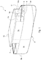
- FIG. 1 a pleasure craft according to a first embodiment of the invention is shown, which craft is indicated as a whole by reference 1.
- the craft 1 comprises a hull 3 in which a bow 3a, a stern 3b, and two flanks 3c, 3d connecting the bow 3a and the stern 3b on opposite sides of the hull 3 are defined.
- the craft 1 also comprises a deck 5 on which a superstructure 7 is provided, which is intended to accommodate one or more passenger cabins and/or a pilot house for the shipowner.
- the superstructure 7 is arranged on the deck 5 in an asymmetrical position with respect to the symmetry plane L of the craft 1, i.e. the plane which is perpendicular to the deck 5 and passes through the bow 3a and the middle point of the stern 3b.
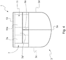
- the outer perimeter of said superstructure 7 comprises: a first lateral wall 7c extending over a certain length along a first flank 3c of the hull between the bow and the stern, substantially aligned with said first flank of the hull; a first transverse wall 7a extending from the bow-facing end of said first lateral wall 7c in a direction substantially transverse to the symmetry plane L of the craft; a second transverse wall 7b extending from the stern-facing end of said first lateral wall 7c in a direction substantially transverse to the symmetry plane L of the craft; a second lateral wall 7d joining the ends of the transverse walls 7a, 7b opposite to those connected to the first lateral wall 7c.
- the distance between the lateral walls 7c, 7d of the superstructure 7 - or, in other words, the width W' of the superstructure 7 - along an axis transverse to the symmetry plane L of the craft is, at each point of the superstructure, smaller than the distance between the flanks 3c, 3d of the hull 3 - or, in other words, than the width W of the deck 5 - along an axis transverse to the symmetry plane L of the craft, so that a free lateral passageway 9 is left on the deck 5 between the second lateral wall 7d of the superstructure 7 and the second flank 3d of the hull 3.
- Said lateral passageway will have a width sufficient for allowing at least the passageway of an individual.
- said superstructure in order to obtain enough space within the superstructure 7, said superstructure will extend - in a direction perpendicular to the symmetry plane L - from the first flank 3c of the hull to the second flank 3d of the hull beyond said symmetry plane, at least along a substantial portion of its length.
- the superstructure 7 has not a uniform width in the direction perpendicular to the symmetry plane L of the craft, but has a reduced width, i.e. it is tapered, at least at one of its ends in the longitudinal direction.
- the superstructure 7 comprises a portion with a reduced width at its end facing the bow of the craft.
- the width of the first transverse wall 7a is smaller than the width of the second transverse wall 7b in a direction transverse to the symmetry plane L of the craft and the second lateral wall 7d comprises a first portion 7d' extending from the end of the second transvers wall 7b in a direction substantially parallel to the symmetry plane L of the craft and a second portion 7d" extending in an oblique direction and joining the first portion 7d' of the second lateral wall 7d to the first transverse wall 7a.
- the plan of the superstructure 7 has the shape of a rectangle with a superimposed scalene trapezoid having its smaller base facing the bow (see Figure 3 ).
- the second lateral wall 7d of the superstructure 7 could have a profile curved towards the bow.
- the first transverse wall 7a will have a width along an axis perpendicular to the symmetry plane L smaller than the maximum width W" of the superstructure 7, i.e. to the maximum distance between said first and second lateral walls of said superstructure along an axis perpendicular to the symmetry plane L.
- the pleasure craft 1 according to the invention has an overall structure which is strongly asymmetrical.
- Such asymmetry is relevant when the craft is viewed frontally (or from behind), i.e. in a direction parallel to the symmetry plane L (direction bow - stern).
- the asymmetrical arrangement of the superstructure 7 involves relevant practical advantages and, in particular, allows to increase the space available inside said structure if compared with a symmetrical arrangement with lateral passageways on both sides ("Walk Around" configuration). Specifically, for the same size of the deck, in the craft according to the invention the space inside the superstructure 7 can be 12 - 15% larger than in a "Walk Around" configuration.
- the asymmetrical arrangement of the superstructure 7 causes an imbalance from the aerodynamic point of view, since the portion of the craft between the symmetry plane L and the side 3c of the hull 3 (i.e. the portion completely occupied by the superstructure 7) offers a significantly higher resistance to air than the portion of the craft between the symmetry plane L and the opposite side 3d of the hull 3 (i.e. the portion only partially occupied by the superstructure 7) and different turbulences are created at the two opposite sides of the hull; the higher the craft speed is and the larger the craft size is, the more relevant are the effects of such imbalance.
- the asymmetrical arrangement of the superstructure 7 gives the craft 1 an awkward profile and generates in the observer an unpleasant impression from the aesthetical point of view.
- the pleasure craft 1 provides for the presence on the deck 5 of a bulkhead 11 which comprises at least a first wall 11a extending from the second flank 3d of the hull 3 in a direction substantially transverse to the symmetry plane L of the craft 1 and substantially coplanar to the first transverse wall 7a of the superstructure 7 and having such a width that the distance d of the end of said first wall 11a of said bulkhead 11 adjacent to the first transverse wall 7a of the superstructure 7 from the symmetry plane L of the craft is equal to or smaller than the maximum distance d' of the second lateral side 7d of the superstructure 7 from said symmetry plane L.
- the height of the first wall 11a of the bulkhead 11 is preferably substantially equal to the height of the walls 7a - 7d of the superstructure 7.
- the presence of the bulkhead 11 reduces the impression of strong asymmetry in the observer and generates a more pleasant impression in such observer.
- the superstructure 7 has a portion with a reduced width at its bow-facing end, i.e. near said first transverse wall 7a: thanks to this configuration, the lateral passageway 9 continuously extends from the stern to the bow, without the need of providing doors or passages in the first wall 11a of the bulkhead 11.
- said lateral passageway 9 comprises a first portion 9' extending along the first portion 7d' of the second lateral wall 7d, in a direction substantially parallel to the symmetry plane L of the craft, and a second portion 9" extending along the second portion 7d" of the second lateral wall 7d, in an oblique direction; the opening 9a of the lateral passageway 9 towards the bow, which extends between the first transverse wall of 7a of the superstructure 7 and the first wall 11a of the bulkhead 11, will be at a distance from the symmetry plane L of the craft smaller than the maximum distance between said symmetry plane L and the second lateral wall 7d of the superstructure 7.
- the opening 9a of the lateral passageway 9 is in a central position with respect to the direction transverse to the symmetry plane L (i.e. astride said symmetry plane), which further contributes to suppress asymmetries in the aerodynamic profile of the pleasure craft 1.
- the opening 9a of the lateral passageway 9 could be provided with a door (e.g. a sliding door or a swinging door) for increasing the symmetry of the structure.
- a door e.g. a sliding door or a swinging door
- the bulkhead 11 has a substantially "L"-shaped profile and comprises - besides the first wall 11a - a second wall 11b extending along the second flank 3d of the hull 3, in a direction substantially orthogonal to said first wall 11a and towards the stern 3b.
- said second wall 11b can advantageously hide the presence of an access door (not shown in the Figures) to the superstructure 7 in the second portion 7d" of the second lateral wall 7d to an external observer viewing the craft from the side.
- the bulkhead 11 will further comprise a third wall 11c extending parallel to the second portion 7d" of the second lateral wall 7d of the superstructure 7 and joining the free ends of said first and second walls 11a, 11b of said bulkhead.
- the free lateral passageway 9 will have a substantially uniform width over its entire length.
- volume enclosed by walls 11a - 11c of the bulkhead 11 can advantageously be used as storage space, for instance for berthing equipment and/or safety equipment.
- the craft 1 further comprises a overhead bridge or flying bridge 13 covering the superstructure 7 and extending in a direction transverse to the symmetry plane L of the craft, across the whole width of the deck 5.
- the bulkhead 11 acts as a support for the flying bridge 13, close to its bow-facing end, on the side of the deck opposite to that along which the superstructure 7 is arranged.
- An upright 15 can be provided for supporting the flying bridge 13 close to its stern-facing end.
- the bulkhead 11 plays an important structural role, since in its absence the flying bridge 13 would be cantilevered on the underlying superstructure 7, which would involve relevant bending stresses or the need of increasing the bearing structures, with a consequent increase in weight, or of adding unaesthetic, separate uprights.
- the bulkhead 11 is permanently, fixedly mounted on the deck 5.
- said bulkhead could be movably, or even removably, mounted on the deck 5.
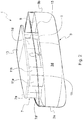
- Said second embodiment differs from the previously described embodiment in that it provides for two bulkheads 11, 21, one at the bow-facing end of the superstructure 7 and the other one at the stern-facing end of the superstructure 7.
- the craft will offer a substantially continuous surface both at its bow and at its stern and the optical impression of a symmetrical surface will be very strong, both when viewing the craft frontally and when viewing it from behind.
- the superstructure 7 is arranged on the deck 5 in an asymmetrical position and the width of the superstructure 7 in a direction transverse to the symmetry plane L of the craft - i.e. the maximum distance between the lateral walls 7c, 7d of said superstructure - is, at each point of the superstructure 7, smaller than the width of the deck 5 in a direction transverse to the symmetry plane L of the craft, whereby a free lateral passageway 9 is left between the second lateral wall 7d of the superstructure 7 and the second flank 3d of the hull 3.
- the superstructure 7 comprises a first portion with reduced width at its bow-facing end and a second portion with reduced width at its stern-facing end.
- the second lateral wall 7d of said superstructure comprises a first, middle portion 7d' extending in a direction substantially parallel to the symmetry plane L of the craft, a second portion 7d" extending in an oblique direction and joining the first portion 7d' of the second lateral wall 7d to the first transverse wall 7a and a third portion 7d"' extending in an oblique direction and joining the first portion 7d' of the second lateral wall 7d to the second transverse wall 7b.
- a first bulkhead 11 which comprises at least a first wall 11a, substantially coplanar to the first transverse wall 7a of the superstructure 7 and extending from the second flank 3d of the hull 3 in a direction substantially transverse to the symmetry plane L of the craft 1 and having such a width that the distance of the end of said first wall 11a of said bulkhead 11 adjacent to the first transverse wall 7a of the superstructure 7 from the symmetry plane L of the craft is equal to or smaller than the maximum distance of the second lateral wall 7d of the superstructure 7 from said symmetry plane L; on the deck 5 a second bulkhead 21 is further provided, which comprises at least a first wall 21a, substantially coplanar to the second transverse wall 7b of the superstructure 7 and extending from the second flank 3d of the hull 3 in a direction substantially transverse to the symmetry plane L of the craft 1 and having such a width that the distance of the end of said first wall 21a of said bulkhead 21 adjacent to the second transverse wall 7
- the height of the first walls 11a, 21a of said bulkheads 11, 21 is preferably equal to the height of the walls 7a - 7d of the superstructure 7. Therefore, the lateral passageway 9 will continuously extend from the stern to the bow and comprise a middle portion 9' extending in a direction substantially parallel to the symmetry plane L of the craft, and oblique portions 9", 9'" extending along the second and third portions 7d", 7d"', respectively, of the second lateral wall 7d.
- the openings 9a, 9b of the lateral passageway 9 towards the bow and the stern will be at a distance from the symmetry plane L of the craft smaller than the maximum distance between said second lateral wall 7d of the superstructure 7 and said symmetry plane L.
- each bulkhead 11, 21 has a substantially "L"-shaped profile and comprises - besides the first wall 11a, 21 - a second wall 11b, 21b, extending along the second flank 3d of the hull 3, in a direction substantially orthogonal to said first wall 11a, 11b and towards the center of the superstructure 7, i.e. towards the stern and towards the bow, respectively.
- each bulkhead 11, 21 will further comprise a third wall 11c, 21c joining the free ends of the walls of each corresponding bulkhead and defining a corresponding enclosed volume which can be advantageously used as storage space.
- the bulkheads 11, 21 are permanently, fixedly mounted on the deck 5, but in an alternative embodiment they could be movably, or even removably, mounted on the deck 5.
- the craft 1 comprises a flying bridge 13 covering the superstructure 7 and extending in a direction transverse to the symmetry plane L of the craft across the whole width of the deck 5, the bulkheads 11, 21 act as supports for the flying bridge 13, both at the stern and at the bow, so that the flying bridge is not cantilevered on the underlying superstructure and there is no need for the presence of separate uprights or for an increase in the bearing structures, with a consequent increase of weight.
- the pleasure craft according to the invention allows to achieve the objects set forth above and combine the practical advantages deriving from an asymmetrical arrangement of the superstructure with a substantially symmetrical aerodynamic profile and a good directional stability and a pleasant appearance.
Landscapes
- Chemical & Material Sciences (AREA)
- Engineering & Computer Science (AREA)
- Combustion & Propulsion (AREA)
- Mechanical Engineering (AREA)
- Ocean & Marine Engineering (AREA)
- Physics & Mathematics (AREA)
- Fluid Mechanics (AREA)
- Vibration Prevention Devices (AREA)
- Toys (AREA)
- Bridges Or Land Bridges (AREA)
- Escalators And Moving Walkways (AREA)
- Developing Agents For Electrophotography (AREA)
- Diaphragms For Electromechanical Transducers (AREA)
- Catalysts (AREA)
- Table Devices Or Equipment (AREA)
- Buildings Adapted To Withstand Abnormal External Influences (AREA)
Claims (12)
- Vergnügungsboot (1) mit:- einem Rumpf (3), der einen Bug (3a), ein Heck (3b), eine Symmetrieebene (L) und zwei Seiten (3c, 3d), die den Bug (3a) mit dem Heck (3b) auf gegenüberliegenden Seiten des Rumpfs relativ zur Symmetrieebene (L) verbinden, aufweist,- einem Deck (5), das im Wesentlichen senkrecht zu der Symmetrieebene ist,- Aufbauten (7), die auf dem Deck (5) angeordnet sind, wobei der äußere Umfang der Aufbauten eine erste Seitenwand (7c), die sich über eine erste Seite (3c) des Rumpfs in eine Richtung im Wesentlichen parallel zur Symmetrieebene (L) des Boots erstreckt und im Wesentlichen mit der ersten Seite des Rumpfs fluchtet, eine erste quer verlaufende Wand (7a), die von dem Ende der ersten Seitenwand (7c), die dem Bug (3a) zugewandt ist, in einer Ebene, die im Wesentlichen quer zur Symmetrieebene (L) des Boots ist, verläuft, eine zweite quer verlaufende Wand (7b), die von dem Ende der ersten Seitenwand (7c), die dem Heck (3b) zugewandt ist, in einer Ebene, die im Wesentlichen quer zu der Symmetrieebene (L) des Boots ist, verläuft, und eine zweite Seitenwand (7d), welche die Enden der ersten und zweiten quer verlaufenden Wände (7a, 7b) an den Enden verbindet, die den durch die erste Seitenwand (7c) verbundenen Enden gegenüberliegen, aufweist,
wobei die Breite (W') zwischen der ersten und der zweiten Seitenwand (7c, 7d) der Aufbauten entlang einer Achse, die senkrecht zur Symmetrieebene ist, kleiner als die Breite (W) zwischen der ersten und der zweiten Seite (3c, 3d) des Rumpfs entlang derselben Achse ist, wodurch ein seitlicher Durchgang (9) zwischen der zweiten Seitenwand (7d) der Aufbauten (7) und der zweiten Seite (3d) des Rumpfs (3) gebildet ist,
wobei die Breite entlang einer Achse, die senkrecht zu der Symmetrieebene von zumindest der ersten quer verlaufenden Wand (7a) der Aufbauten ist, kleiner als die maximale Breite (W") zwischen der ersten und der zweiten Seitenwand (7c, 7d) der Aufbauten ist,
dadurch gekennzeichnet, dass wenigstens eine Querwand (11) auf dem Deck (5) angeordnet ist, wobei die Querwand wenigstens eine erste Wand (11a) aufweist, die von der zweiten Seite (3d) des Rumpfs (3) ausgeht und im Wesentlichen koplanar mit der ersten quer verlaufenden Wand (7a) der Aufbauten ist, wobei die erste Wand (11a) der Querwand (11) entlang einer Achse, die senkrecht zur Symmetrieebene (L) ist, eine solche Breite hat, dass der Abstand (d) des Endes der ersten Wand (11a) der Querwand (11), das an die erste quer verlaufende Wand angrenzt, von der Symmetrieebene (11) gleich wie oder kleiner als der maximale Abstand (d') der zweiten Seitenwand (7d) der Aufbauten (7) von der Symmetrieebene (L) ist, und dass die quer verlaufenden Wände (7a, 7b) und die Seitenwände (7c, 7d) der Aufbauten (7) alle dieselbe Höhe haben, und wobei die Höhe der ersten Wand (11a) der Querwand (11) im Wesentlichen genauso groß ist wie die Höhe der Wände (7a - 7d) der Aufbauten. - Vergnügungsboot (1) nach Anspruch 1, wobei die Aufbauten (7) einen Abschnitt haben, der in der Nähe der ersten quer verlaufenden Wand (7a) eine kleinere Breite hat.
- Vergnügungsboot (1) nach Anspruch 1, wobei die Querwand (11) zudem eine zweite Wand (11b) aufweist, die sich zu dem Heck (3b) hin in einer Richtung erstreckt, die im Wesentlichen senkrecht zu der ersten Wand (11a) der Querwand ist und im Wesentlichen mit der zweiten Seite (3d) des Rumpfs fluchtet.
- Vergnügungsboot (1) nach Anspruch 1, wobei eine zweite Querwand (21) auf dem Deck (5) angeordnet ist, wobei die zweite Querwand zumindest eine erste Wand (21a) aufweist, die von der zweiten Seite (3d) des Rumpfs (3) ausgeht und im Wesentlichen koplanar mit der zweiten quer verlaufenden Wand (7b) der Aufbauten (7) ist, wobei die erste Wand (21a) der zweiten Querwand (21) eine solche Breite entlang einer Achse hat, die senkrecht zur Symmetrieebene (L) ist, dass der Abstand (d) des Endes der ersten Wand (21a) der zweiten Querwand (21), das an die zweite quer verlaufende Wand angrenzt, von der Symmetrieebene (L) gleich wie oder kleiner als der maximale Abstand (d') der zweiten Seitenwand (7d) der Aufbauten (7) von der Symmetrieebene (L) ist.
- Vergnügungsboot (1) nach Anspruch 4, wobei die quer verlaufenden Wände (7a, 7b) und die Seitenwände (7c, 7d) der Aufbauten (7) alle dieselbe Höhe haben und wobei die Höhe der ersten Wand (21a) der zweiten Querwand (21) im Wesentlichen genauso groß wie die Höhe der Wände (7a - 7d) der Aufbauten ist.
- Vergnügungsboot (1) nach Anspruch 4, wobei die Aufbauten (7) einen zweiten Abschnitt aufweisen, der in der Nähe der zweiten quer verlaufenden Wand (7b) eine kleinere Breite hat.
- Vergnügungsboot (1) nach Anspruch 4, wobei die zweite Querwand (21) zudem eine zweite Wand (21b) aufweist, die sich zu dem Bug (3a) in einer Richtung erstreckt, die im Wesentlichen senkrecht zu der ersten Wand (21a) der Querwand ist, und im Wesentlichen mit der zweiten Seite (3d) des Rumpfs fluchtet.
- Vergnügungsboot (1) nach Anspruch 3, wobei die Querwand (11) zudem eine dritte Wand (11c) aufweist, welche die freien Enden der ersten und der zweiten Wand (11a, 11b) der Querwand verbindet.
- Vergnügungsboot (1) nach Anspruch 7, wobei die zweite Querwand (21) zudem eine dritte Wand (21c) aufweist, welche die freien Enden der ersten und der zweiten Wand (21a, 21b) der Querwand verbindet.
- Vergnügungsboot (1) nach einem der Ansprüche 1 bis 9, wobei die Querwand (11) und, falls vorhanden, die zweite Querwand (21) fest und dauerhaft auf dem Deck (5) montiert sind.
- Vergnügungsboot (1) nach einem der Ansprüche 1 bis 9, wobei die Querwand (11) und, falls vorhanden, die zweite Querwand (21) beweglich und/oder abnehmbar an dem Deck (5) montiert sind.
- Vergnügungsboot (1) nach einem der vorstehenden Ansprüche, wobei das Boot (1) eine Laufbrücke (13) aufweist, welche die Aufbauten (7) bedeckt und sich in einer Richtung, die quer zu der Symmetrieebene (L) des Boots ist, über die gesamte Breite des Decks (5) erstreckt, und wobei die Querwand (11) und, falls vorhanden, die zweite Querwand (21) als Stützen für die Laufbrücke (13) dienen.
Priority Applications (1)
| Application Number | Priority Date | Filing Date | Title |
|---|---|---|---|
| PL17787246T PL3472034T3 (pl) | 2016-06-15 | 2017-06-07 | Łódź rekreacyjna |
Applications Claiming Priority (2)
| Application Number | Priority Date | Filing Date | Title |
|---|---|---|---|
| ITUA2016A004403A ITUA20164403A1 (it) | 2016-06-15 | 2016-06-15 | Imbarcazione da diporto |
| PCT/IB2017/053347 WO2017216684A1 (en) | 2016-06-15 | 2017-06-07 | Pleasure craft |
Publications (2)
| Publication Number | Publication Date |
|---|---|
| EP3472034A1 EP3472034A1 (de) | 2019-04-24 |
| EP3472034B1 true EP3472034B1 (de) | 2020-05-13 |
Family
ID=57209694
Family Applications (1)
| Application Number | Title | Priority Date | Filing Date |
|---|---|---|---|
| EP17787246.2A Active EP3472034B1 (de) | 2016-06-15 | 2017-06-07 | Freizeitboot |
Country Status (12)
| Country | Link |
|---|---|
| EP (1) | EP3472034B1 (de) |
| KR (1) | KR102279527B1 (de) |
| CN (1) | CN109328160B (de) |
| AU (1) | AU2017286768B2 (de) |
| BR (1) | BR112018076170B1 (de) |
| DE (1) | DE202017007156U1 (de) |
| ES (1) | ES2805033T3 (de) |
| IT (1) | ITUA20164403A1 (de) |
| MX (1) | MX2018015395A (de) |
| PL (1) | PL3472034T3 (de) |
| RU (1) | RU2706759C1 (de) |
| WO (1) | WO2017216684A1 (de) |
Family Cites Families (11)
| Publication number | Priority date | Publication date | Assignee | Title |
|---|---|---|---|---|
| GB1180107A (en) * | 1967-07-25 | 1970-02-04 | Dartmouth Aero Marine Ltd | Improvements in and relating to Yachts. |
| US4064584A (en) * | 1976-09-13 | 1977-12-27 | James Harold Funkhouser | Upper boat deck |
| IT1227143B (it) * | 1988-09-26 | 1991-03-19 | Fincantieri Cantieri Navali It | Nave passeggeri con distinti spazi liberi a murata |
| FR2831133B1 (fr) * | 2001-10-23 | 2004-01-23 | Laurent Maurice Mermier | Navire de croisiere ou de loisirs de grande largeur |
| KR100507853B1 (ko) * | 2002-12-17 | 2005-08-17 | 허식 | 자항 바지선 |
| FI20095055A0 (fi) * | 2009-01-23 | 2009-01-23 | Stx Finland Cruise Oy | Kelluva rakenne, alus, tai vastaava |
| FR2974346B1 (fr) * | 2011-04-22 | 2013-05-24 | Stx France Sa | Navire a passagers dont la superstructure est pourvue d'au moins une arche |
| CN202414090U (zh) * | 2011-12-30 | 2012-09-05 | 广东江龙船舶制造有限公司 | 铝合金-玻璃钢复合船 |
| CN202642045U (zh) * | 2012-06-27 | 2013-01-02 | 安庆三维电器有限公司 | 船用整体厨房 |
| CN202966577U (zh) * | 2012-12-18 | 2013-06-05 | 广东江龙船舶制造有限公司 | 钢-玻璃钢复合船 |
| CN205150156U (zh) * | 2015-10-23 | 2016-04-13 | 上海船舶研究设计院 | 一种船舶新型上层建筑舱室结构 |
-
2016
- 2016-06-15 IT ITUA2016A004403A patent/ITUA20164403A1/it unknown
-
2017
- 2017-06-07 EP EP17787246.2A patent/EP3472034B1/de active Active
- 2017-06-07 ES ES17787246T patent/ES2805033T3/es active Active
- 2017-06-07 CN CN201780037558.9A patent/CN109328160B/zh active Active
- 2017-06-07 RU RU2018144343A patent/RU2706759C1/ru active
- 2017-06-07 BR BR112018076170-2A patent/BR112018076170B1/pt active IP Right Grant
- 2017-06-07 PL PL17787246T patent/PL3472034T3/pl unknown
- 2017-06-07 DE DE202017007156.8U patent/DE202017007156U1/de active Active
- 2017-06-07 KR KR1020187036033A patent/KR102279527B1/ko active Active
- 2017-06-07 AU AU2017286768A patent/AU2017286768B2/en active Active
- 2017-06-07 MX MX2018015395A patent/MX2018015395A/es unknown
- 2017-06-07 WO PCT/IB2017/053347 patent/WO2017216684A1/en not_active Ceased
Non-Patent Citations (1)
| Title |
|---|
| None * |
Also Published As
| Publication number | Publication date |
|---|---|
| KR102279527B1 (ko) | 2021-07-20 |
| EP3472034A1 (de) | 2019-04-24 |
| RU2706759C1 (ru) | 2019-11-20 |
| WO2017216684A1 (en) | 2017-12-21 |
| ITUA20164403A1 (it) | 2017-12-15 |
| BR112018076170B1 (pt) | 2023-12-26 |
| CN109328160B (zh) | 2021-03-26 |
| AU2017286768B2 (en) | 2022-03-31 |
| PL3472034T3 (pl) | 2021-06-14 |
| AU2017286768A1 (en) | 2018-12-13 |
| KR20190018430A (ko) | 2019-02-22 |
| NZ748636A (en) | 2021-03-26 |
| DE202017007156U1 (de) | 2019-10-14 |
| CN109328160A (zh) | 2019-02-12 |
| MX2018015395A (es) | 2019-04-29 |
| ES2805033T3 (es) | 2021-02-10 |
| BR112018076170A2 (pt) | 2019-03-26 |
Similar Documents
| Publication | Publication Date | Title |
|---|---|---|
| AU2012305681B2 (en) | Water craft having open upper deck, aft swim deck and collapsible bulwarks | |
| ES2451500T3 (es) | Disposición de una proa de una embarcación del tipo de desplazamiento | |
| EP3305651A1 (de) | Angelenkt schlepper-barge rumpf | |
| AU2017286768B2 (en) | Pleasure craft | |
| NZ748636B2 (en) | Pleasure craft | |
| WO2011117906A1 (en) | Planing hull with innovative bottom | |
| WO2018150912A1 (ja) | 船体構造 | |
| JP5385195B2 (ja) | 船舶 | |
| WO2017081996A1 (ja) | 船舶 | |
| US20220153391A1 (en) | Wake enhancing boat hull | |
| US6755143B2 (en) | Wide cruise ship or pleasure boat | |
| WO2016158880A1 (ja) | 船舶 | |
| US5072681A (en) | Passenger ship | |
| US12559203B2 (en) | Pleasure craft having an improved deck construction | |
| JP2012017022A (ja) | 船舶の風圧抵抗低減構造及び船舶 | |
| NL2018697B1 (nl) | Vaartuig | |
| JP2013154756A (ja) | 多胴船 | |
| JP3949895B2 (ja) | 全包囲型船橋ウイング | |
| US20070261623A1 (en) | Multi-hull boat | |
| JPS6154397A (ja) | 2軸2舵式高速船 | |
| GB2503412A (en) | Floating vessel with widened deck area at its bow end | |
| JPH0528797U (ja) | 滑走型高速艇 | |
| Yun et al. | Seakeeping | |
| CA2944301A1 (en) | Articulating tug barge hull | |
| Miskovic | Product Analysis and Design of a Superyacht Analysis of a semi-custom fiberglass range of Benetti Yachts, from 93’to 145’Redesign of a “Classic” 121’Yacht |
Legal Events
| Date | Code | Title | Description |
|---|---|---|---|
| REG | Reference to a national code |
Ref country code: DE Ref legal event code: R138 Ref document number: 202017007156 Country of ref document: DE Free format text: GERMAN DOCUMENT NUMBER IS 602017016797 |
|
| STAA | Information on the status of an ep patent application or granted ep patent |
Free format text: STATUS: UNKNOWN |
|
| STAA | Information on the status of an ep patent application or granted ep patent |
Free format text: STATUS: THE INTERNATIONAL PUBLICATION HAS BEEN MADE |
|
| PUAI | Public reference made under article 153(3) epc to a published international application that has entered the european phase |
Free format text: ORIGINAL CODE: 0009012 |
|
| STAA | Information on the status of an ep patent application or granted ep patent |
Free format text: STATUS: REQUEST FOR EXAMINATION WAS MADE |
|
| 17P | Request for examination filed |
Effective date: 20181211 |
|
| AK | Designated contracting states |
Kind code of ref document: A1 Designated state(s): AL AT BE BG CH CY CZ DE DK EE ES FI FR GB GR HR HU IE IS IT LI LT LU LV MC MK MT NL NO PL PT RO RS SE SI SK SM TR |
|
| AX | Request for extension of the european patent |
Extension state: BA ME |
|
| DAV | Request for validation of the european patent (deleted) | ||
| DAX | Request for extension of the european patent (deleted) | ||
| GRAP | Despatch of communication of intention to grant a patent |
Free format text: ORIGINAL CODE: EPIDOSNIGR1 |
|
| STAA | Information on the status of an ep patent application or granted ep patent |
Free format text: STATUS: GRANT OF PATENT IS INTENDED |
|
| INTG | Intention to grant announced |
Effective date: 20191210 |
|
| GRAS | Grant fee paid |
Free format text: ORIGINAL CODE: EPIDOSNIGR3 |
|
| GRAA | (expected) grant |
Free format text: ORIGINAL CODE: 0009210 |
|
| STAA | Information on the status of an ep patent application or granted ep patent |
Free format text: STATUS: THE PATENT HAS BEEN GRANTED |
|
| AK | Designated contracting states |
Kind code of ref document: B1 Designated state(s): AL AT BE BG CH CY CZ DE DK EE ES FI FR GB GR HR HU IE IS IT LI LT LU LV MC MK MT NL NO PL PT RO RS SE SI SK SM TR |
|
| REG | Reference to a national code |
Ref country code: GB Ref legal event code: FG4D |
|
| REG | Reference to a national code |
Ref country code: CH Ref legal event code: EP |
|
| REG | Reference to a national code |
Ref country code: DE Ref legal event code: R096 Ref document number: 602017016797 Country of ref document: DE |
|
| REG | Reference to a national code |
Ref country code: AT Ref legal event code: REF Ref document number: 1269914 Country of ref document: AT Kind code of ref document: T Effective date: 20200615 |
|
| REG | Reference to a national code |
Ref country code: NL Ref legal event code: FP |
|
| REG | Reference to a national code |
Ref country code: LT Ref legal event code: MG4D |
|
| REG | Reference to a national code |
Ref country code: GR Ref legal event code: EP Ref document number: 20200402170 Country of ref document: GR Effective date: 20201014 |
|
| PG25 | Lapsed in a contracting state [announced via postgrant information from national office to epo] |
Ref country code: PT Free format text: LAPSE BECAUSE OF FAILURE TO SUBMIT A TRANSLATION OF THE DESCRIPTION OR TO PAY THE FEE WITHIN THE PRESCRIBED TIME-LIMIT Effective date: 20200914 Ref country code: IS Free format text: LAPSE BECAUSE OF FAILURE TO SUBMIT A TRANSLATION OF THE DESCRIPTION OR TO PAY THE FEE WITHIN THE PRESCRIBED TIME-LIMIT Effective date: 20200913 Ref country code: SE Free format text: LAPSE BECAUSE OF FAILURE TO SUBMIT A TRANSLATION OF THE DESCRIPTION OR TO PAY THE FEE WITHIN THE PRESCRIBED TIME-LIMIT Effective date: 20200513 Ref country code: FI Free format text: LAPSE BECAUSE OF FAILURE TO SUBMIT A TRANSLATION OF THE DESCRIPTION OR TO PAY THE FEE WITHIN THE PRESCRIBED TIME-LIMIT Effective date: 20200513 Ref country code: NO Free format text: LAPSE BECAUSE OF FAILURE TO SUBMIT A TRANSLATION OF THE DESCRIPTION OR TO PAY THE FEE WITHIN THE PRESCRIBED TIME-LIMIT Effective date: 20200813 Ref country code: LT Free format text: LAPSE BECAUSE OF FAILURE TO SUBMIT A TRANSLATION OF THE DESCRIPTION OR TO PAY THE FEE WITHIN THE PRESCRIBED TIME-LIMIT Effective date: 20200513 |
|
| PG25 | Lapsed in a contracting state [announced via postgrant information from national office to epo] |
Ref country code: BG Free format text: LAPSE BECAUSE OF FAILURE TO SUBMIT A TRANSLATION OF THE DESCRIPTION OR TO PAY THE FEE WITHIN THE PRESCRIBED TIME-LIMIT Effective date: 20200813 Ref country code: RS Free format text: LAPSE BECAUSE OF FAILURE TO SUBMIT A TRANSLATION OF THE DESCRIPTION OR TO PAY THE FEE WITHIN THE PRESCRIBED TIME-LIMIT Effective date: 20200513 Ref country code: HR Free format text: LAPSE BECAUSE OF FAILURE TO SUBMIT A TRANSLATION OF THE DESCRIPTION OR TO PAY THE FEE WITHIN THE PRESCRIBED TIME-LIMIT Effective date: 20200513 Ref country code: LV Free format text: LAPSE BECAUSE OF FAILURE TO SUBMIT A TRANSLATION OF THE DESCRIPTION OR TO PAY THE FEE WITHIN THE PRESCRIBED TIME-LIMIT Effective date: 20200513 |
|
| REG | Reference to a national code |
Ref country code: AT Ref legal event code: MK05 Ref document number: 1269914 Country of ref document: AT Kind code of ref document: T Effective date: 20200513 |
|
| PG25 | Lapsed in a contracting state [announced via postgrant information from national office to epo] |
Ref country code: AL Free format text: LAPSE BECAUSE OF FAILURE TO SUBMIT A TRANSLATION OF THE DESCRIPTION OR TO PAY THE FEE WITHIN THE PRESCRIBED TIME-LIMIT Effective date: 20200513 |
|
| PG25 | Lapsed in a contracting state [announced via postgrant information from national office to epo] |
Ref country code: SM Free format text: LAPSE BECAUSE OF FAILURE TO SUBMIT A TRANSLATION OF THE DESCRIPTION OR TO PAY THE FEE WITHIN THE PRESCRIBED TIME-LIMIT Effective date: 20200513 Ref country code: EE Free format text: LAPSE BECAUSE OF FAILURE TO SUBMIT A TRANSLATION OF THE DESCRIPTION OR TO PAY THE FEE WITHIN THE PRESCRIBED TIME-LIMIT Effective date: 20200513 Ref country code: IT Free format text: LAPSE BECAUSE OF FAILURE TO SUBMIT A TRANSLATION OF THE DESCRIPTION OR TO PAY THE FEE WITHIN THE PRESCRIBED TIME-LIMIT Effective date: 20200513 Ref country code: AT Free format text: LAPSE BECAUSE OF FAILURE TO SUBMIT A TRANSLATION OF THE DESCRIPTION OR TO PAY THE FEE WITHIN THE PRESCRIBED TIME-LIMIT Effective date: 20200513 Ref country code: DK Free format text: LAPSE BECAUSE OF FAILURE TO SUBMIT A TRANSLATION OF THE DESCRIPTION OR TO PAY THE FEE WITHIN THE PRESCRIBED TIME-LIMIT Effective date: 20200513 Ref country code: CZ Free format text: LAPSE BECAUSE OF FAILURE TO SUBMIT A TRANSLATION OF THE DESCRIPTION OR TO PAY THE FEE WITHIN THE PRESCRIBED TIME-LIMIT Effective date: 20200513 Ref country code: RO Free format text: LAPSE BECAUSE OF FAILURE TO SUBMIT A TRANSLATION OF THE DESCRIPTION OR TO PAY THE FEE WITHIN THE PRESCRIBED TIME-LIMIT Effective date: 20200513 |
|
| REG | Reference to a national code |
Ref country code: CH Ref legal event code: PL |
|
| REG | Reference to a national code |
Ref country code: ES Ref legal event code: FG2A Ref document number: 2805033 Country of ref document: ES Kind code of ref document: T3 Effective date: 20210210 |
|
| REG | Reference to a national code |
Ref country code: DE Ref legal event code: R097 Ref document number: 602017016797 Country of ref document: DE |
|
| PG25 | Lapsed in a contracting state [announced via postgrant information from national office to epo] |
Ref country code: SK Free format text: LAPSE BECAUSE OF FAILURE TO SUBMIT A TRANSLATION OF THE DESCRIPTION OR TO PAY THE FEE WITHIN THE PRESCRIBED TIME-LIMIT Effective date: 20200513 Ref country code: MC Free format text: LAPSE BECAUSE OF FAILURE TO SUBMIT A TRANSLATION OF THE DESCRIPTION OR TO PAY THE FEE WITHIN THE PRESCRIBED TIME-LIMIT Effective date: 20200513 |
|
| PLBE | No opposition filed within time limit |
Free format text: ORIGINAL CODE: 0009261 |
|
| STAA | Information on the status of an ep patent application or granted ep patent |
Free format text: STATUS: NO OPPOSITION FILED WITHIN TIME LIMIT |
|
| PG25 | Lapsed in a contracting state [announced via postgrant information from national office to epo] |
Ref country code: LU Free format text: LAPSE BECAUSE OF NON-PAYMENT OF DUE FEES Effective date: 20200607 |
|
| REG | Reference to a national code |
Ref country code: BE Ref legal event code: MM Effective date: 20200630 |
|
| 26N | No opposition filed |
Effective date: 20210216 |
|
| PG25 | Lapsed in a contracting state [announced via postgrant information from national office to epo] |
Ref country code: LI Free format text: LAPSE BECAUSE OF NON-PAYMENT OF DUE FEES Effective date: 20200630 Ref country code: IE Free format text: LAPSE BECAUSE OF NON-PAYMENT OF DUE FEES Effective date: 20200607 Ref country code: CH Free format text: LAPSE BECAUSE OF NON-PAYMENT OF DUE FEES Effective date: 20200630 |
|
| PG25 | Lapsed in a contracting state [announced via postgrant information from national office to epo] |
Ref country code: BE Free format text: LAPSE BECAUSE OF NON-PAYMENT OF DUE FEES Effective date: 20200630 Ref country code: SI Free format text: LAPSE BECAUSE OF FAILURE TO SUBMIT A TRANSLATION OF THE DESCRIPTION OR TO PAY THE FEE WITHIN THE PRESCRIBED TIME-LIMIT Effective date: 20200513 |
|
| PG25 | Lapsed in a contracting state [announced via postgrant information from national office to epo] |
Ref country code: MT Free format text: LAPSE BECAUSE OF FAILURE TO SUBMIT A TRANSLATION OF THE DESCRIPTION OR TO PAY THE FEE WITHIN THE PRESCRIBED TIME-LIMIT Effective date: 20200513 Ref country code: CY Free format text: LAPSE BECAUSE OF FAILURE TO SUBMIT A TRANSLATION OF THE DESCRIPTION OR TO PAY THE FEE WITHIN THE PRESCRIBED TIME-LIMIT Effective date: 20200513 |
|
| PG25 | Lapsed in a contracting state [announced via postgrant information from national office to epo] |
Ref country code: MK Free format text: LAPSE BECAUSE OF FAILURE TO SUBMIT A TRANSLATION OF THE DESCRIPTION OR TO PAY THE FEE WITHIN THE PRESCRIBED TIME-LIMIT Effective date: 20200513 |
|
| P01 | Opt-out of the competence of the unified patent court (upc) registered |
Effective date: 20230518 |
|
| PGFP | Annual fee paid to national office [announced via postgrant information from national office to epo] |
Ref country code: DE Payment date: 20250620 Year of fee payment: 9 Ref country code: PL Payment date: 20250605 Year of fee payment: 9 |
|
| PGFP | Annual fee paid to national office [announced via postgrant information from national office to epo] |
Ref country code: GB Payment date: 20250625 Year of fee payment: 9 |
|
| PGFP | Annual fee paid to national office [announced via postgrant information from national office to epo] |
Ref country code: NL Payment date: 20250627 Year of fee payment: 9 |
|
| PGFP | Annual fee paid to national office [announced via postgrant information from national office to epo] |
Ref country code: FR Payment date: 20250522 Year of fee payment: 9 |
|
| PGFP | Annual fee paid to national office [announced via postgrant information from national office to epo] |
Ref country code: GR Payment date: 20250626 Year of fee payment: 9 |
|
| PGFP | Annual fee paid to national office [announced via postgrant information from national office to epo] |
Ref country code: TR Payment date: 20250602 Year of fee payment: 9 |
|
| PGFP | Annual fee paid to national office [announced via postgrant information from national office to epo] |
Ref country code: ES Payment date: 20250828 Year of fee payment: 9 |